)LHOG ,QVWDOODWLRQ ,QVWUXFWLRQV 6ZLQJLQJ 6FUHHQ 'RRU€¦ · 6ZLQJLQJ 6FUHHQ 'RRU ) ... SWINGING...
21
SWINGING SCREEN DOOR FIELD INSTALLATION INSTRUCTIONS
Transcript of )LHOG ,QVWDOODWLRQ ,QVWUXFWLRQV 6ZLQJLQJ 6FUHHQ 'RRU€¦ · 6ZLQJLQJ 6FUHHQ 'RRU ) ... SWINGING...

SWINGING SCREEN DOORFIELD INSTALLATION INSTRUCTIONS
Read these instructions thoroughly before beginning to install your hinged screen door for the InswingFrench/Terrace Door. Failure to install as recommended will void any warranty, written or implied. Regional applications and standards may vary; therefore Loewen is not responsible for interpretations of local codes and/or ordinances. Installation of Loewen products is the sole responsibility of the installer, contractor, structural engineer, architect, building owner and/or consumer. After installation is completed, these instructions should be retained bythe building owner. For additional information, consult your local Loewen dealer.


1
1: Measuring the Opening for the Storm Door ....................................................................................... 4
2: Securing Storm Door Hinge Side Frame into Door Frame ............................................................... 6
3: Securing Storm Door Head Frame into Door Frame ........................................................................ 7
4: Securing Storm Door Latch Side Frame into Door Frame ............................................................... 7
5: Strike Plates Installation (French Doors Only) .................................................................................. 8
6: Screen Panel Installation ................................................................................................................... 8
7: Door Closer Installation ...................................................................................................................... 9
8: Latch Handle Installation.................................................................................................................. 10
9: Door/Lock Keeper Installation (Terrace Door) ................................................................................ 10
10: Screen and Storm Panel Insert Installation .................................................................................. 10
1B: Jamb Drilling Details for On-site Retrofit (Terrace Door) ............................................................ 12
2B: Jamb Machining Details for On-site Retrofit (Terrace Door) ....................................................... 13
3B: Head and Sill Machining for Strike Plates ..................................................................................... 15
Figure 2: Strike Plates Installation ........................................................................................................ 8
Figure 3: Screen Panel Installation ....................................................................................................... 8
Figure 4: Door Closer Installation .......................................................................................................... 9
Figure 5: Latch Handle Installation ...................................................................................................... 10
Figure 6: Latch & Lock Keeper Installation ......................................................................................... 10
Figure 7: Screen and Storm Panel Insert Installation ........................................................................ 10
Figure 8: Jamb Drilling Details for On-Site Retrofit ........................................................................... 11
TABLE OF CONTENTS
Information is subject to change without notice. | CAD Download and Installation Instructions: www.loewen.com
FIGURES

2
NOTICES AND INFORMATION:
Read these instructions in their entirety prior to installing doors. Contact Loewen at 1.800.563.9367 for clarification.
• Any local building code requirements supersede these recommended installation instructions.
• Building design, construction methods, building materials and site conditions unique to your project may require an installation method different from these instructions, and additional care.
• Remove shipping blocks and related staples prior to installation
FOR TYPICAL WOOD FRAME CONSTRUCTION:• These instructions were developed and tested for use with
typical wood frame wall construction in a wall system designed to manage water, with a weather resistant barrier applied prior to the door installation.
• These instructions are not to be used with other construction methods.
PRECAUTIONS AND SAFETY:
• Do not work alone. It is recommended that at least two people work together to avoid personal injury or damage when working with doors.
• Use caution when handling glass. Broken or cracked glass can cause serious injury.
• Wear necessary protective gear (gloves, clothing, goggles, etc.).
• Secure tools, ladders or scaffolding. Follow equipment manufacturers’ operation instructions, warnings and cautions.
• Secure and properly support the unit until completely fastened.
Information is subject to change without notice. | CAD Download and Installation Instructions: www.loewen.com
IMPORTANT!
Read these instructions thoroughly before beginning to install your hinged screen door for the Inswing Terrace/French Door. Failure to install as recommended will void any warranty, written or implied. Regional applications and standards may vary; therefore Loewen is not responsible for interpretations of local codes and/or ordinances. Installation of Loewen products is the sole responsibility of the installer, contractor, structural engineer, architect, building owner and/or consumer. After installation is completed, these instructions should be retained by the building owner. For additional information, consult your local Loewen dealer.

One screen door package will be provided per Terrace/French door. Ensure all necessary parts are included in the package. If replacement parts are required, please contact your local Loewen dealer.
Table 1: Parts Shipped for Terrace/French Door Inswing Screen Installation
FRENCH DOOR TERRACE DOOR
1
Active screen door panel (QTY: 1) Passive screen door panel(QTY: 1) (with astragal, flush bolts andlock keeper)
Active screen door panel (QTY: 1)
2
Screen panel insert (QTY: 2)
Screen panel insert (QTY: 1)
3
Storm panel (optional) (QTY: 2)
Storm panel (optional) (QTY: 1)
4
A. Screen door frame - Head (QTY: 1) B. Hinge jamb (with hinge leafs) (QTY: 1) C. Lock jamb (QTY: 1)
A. Screen door frame - Head (QTY: 1)B. Hinge jamb (with hinge leafs) (QTY: 1) C. Lock jamb (QTY: 1)
5
Strike plate (QTY: 2)
Information is subject to change without notice. | CAD Download and Installation Instructions: www.loewen.com
3
ww
w.l
oew
en.c
om
| 1
.800
.563
.936
7 |
S
WIN
GIN
G S
CR
EE
N D
OO
R I
NS
TAL
LA
TIO
N G
UID
E

Information is subject to change without notice. CAD Download and Installation Instructions: www.loewen.com
6
Door closer (QTY: 4) Door closer (QTY: 2)
7
K-Lathe screw #8 x5/8” (QTY: SIZE DEPENDANT)
Flat Head screw #6x3/4” (QTY: 4)
K-Lathe screw #8 x 5/8” (QTY: SIZE DEPENDANT)
8
Latch handle - Concord (Standard) (QTY: 1)
Latch handle - Concord (Standard) (QTY: 1) Latch handle – Concord (Standard) (QTY: 1)
9
Latch handle – Thompson (Optional) (QTY: 1)
Latch handle - Thompson (Optional) (QTY: 1)
10
Latch handle – Tampa (Optional) (QTY:1)
Latch handle – Tampa (Optional) (QTY:1)
11
Shim 80mm×33mm×1.6mm(QTY:19)
Shim 80mm×33mm×1.6mm(QTY:19)
4
ww
w.l
oew
en.c
om
| 1
.800
.563
.936
7 |
S
WIN
GIN
G S
CR
EE
N D
OO
R I
NS
TAL
LA
TIO
N G
UID
E

5
INSTRUCTIONS FOR PANELS ORDERED WITH DOORS
Information is subject to change without notice. | CAD Download and Installation Instructions: www.loewen.com
The following section contains installation instructions for factory prepared units, where the screens where initially ordered with the doors.
Width: From the exterior, measure the width of the Door Frame opening - between the Side Frame Cladding (metal clad units) or between Side Casing (non-clad units) of the Door Frame. Take this measurement at three locations, head (top), middle and sill (bottom).
STEP 1: MEASURING THE OPENING FOR THE STORM DOOR
1. Head
2. Middle
3. Sill
METAL CLAD
WIDTH MEASUREMENT
NON CLAD
WIDTH MEASUREMENT
SILL
ww
w.l
oew
en.c
om
| 1
.800
.563
.936
7 |
S
WIN
GIN
G S
CR
EE
N D
OO
R I
NS
TAL
LA
TIO
N G
UID
E

6
Information is subject to change without notice. | CAD Download and Installation Instructions: www.loewen.com
Height: From the exterior, measure the height of the Door Frame opening – from the Frame Head Cladding or Casing and the sill of the door. Take this measurement at three locations, at the latch side, middle and hinge side.
1. Hinge/Latch 2. Middle 3. Hinge/Latch
METAL CLAD HEAD
HEIGHTMEASUREMENT
HEIGHTMEASUREMENT
NON CLAD HEAD
SILL
HEIGHTMEASUREMENT
Depending on the trueness of the Door Frame opening the Storm Door is being Installed into, shimming may be necessary. Shimming materials are by others.
ww
w.l
oew
en.c
om
| 1
.800
.563
.936
7 |
S
WIN
GIN
G S
CR
EE
N D
OO
R I
NS
TAL
LA
TIO
N G
UID
E

7
Information is subject to change without notice. | CAD Download and Installation Instructions: www.loewen.com
1. If shims are necessary, attach shims to the Door Frame opening using tape so they remain in place while pre-drilling the mounting holes. Shims should be placed behind each hinge and each mounting hole location in theStorm Door Frame.
STEP 2. SECURING STORM DOOR HINGE SIDE FRAME INTO DOOR FRAME
2. With the smallest width dimension in mind from Step 1, shim as necessary between the Storm Door Frame andDoor Frame to ensure that the reveals between the Storm Door panel and Frame are even and consistent.
3. The Storm Door’s ‘Hinge Side Frame’ into the Door Frame opening and mark the pre-drilled holes. Thenremove the ‘Hinge Side Frame’ and attach the Hinge Leaves to the Storm Door Panel using the screws andpre-drilled holes provided. Drill the holes marked in the ‘Pre-fit’ step above. Place the Storm Door Panel and‘Hinge Side Frame’ assembly into the Door Frame opening and secure through the pre-drilled holes with thesupplied screws ensuring the panel is plumb and the Storm Door Frame is shimmed as required.
Pre-drill holes
Shims
Hinge
Weather Stripping
Hinge Side Frame
Hinge Screws
Hinge
ww
w.l
oew
en.c
om
| 1
.800
.563
.936
7 |
S
WIN
GIN
G S
CR
EE
N D
OO
R I
NS
TAL
LA
TIO
N G
UID
E

Information is subject to change without notice. | CAD Download and Installation Instructions: www.loewen.com
1. If shims are necessary, attach shims to the Door Frame opening using tape so they remain in place while pre-drilling the mounting holes in the Door Frame. Shims should be placed at each mounting hole location in theStorm Door Frame.
2. With the smallest height dimension in mind from Step 1, shim as necessary between the Storm Door Frameand Door Frame opening to ensure that the reveals between the Storm Door Panel and Frame are even andconsistent. Place Storm Door ‘Head Frame’ into Door Frame opening and pre-drill into Door Frame using theholes in the Storm Door Frame as a guide. Using screws provided, secure Storm Door ‘Head Frame’ to theDoor Frame opening.
STEP 3. SECURING STORM DOOR HEAD FRAME INTO DOOR FRAME
Frame Cladding
Shims
Head Frame
Head Screw
HEAD FRAME
1. If shims are necessary, attach shims to the Door Frame opening using tape so they remain in place while pre-drilling the mounting holes in the Door Frame. Shims should be placed at each mounting hole location in theStorm Door Frame.
2. Shim as necessary between the Storm Door ‘Latch Side Frame’ and Door Frame opening to ensure that thereveals between the Storm Door Panel and Frame are even and consistent. Place Storm Door ‘Latch SideFrame’ into Door Frame opening and pre-drill into Door Frame using the holes in the Storm Door Frame as aguide. Using screws provided, secure Storm Door ‘Latch Side Frame’ to Door Frame.
STEP 4. SECURING STORM DOOR LATCH SIDE FRAME INTO DOOR FRAME
Pre-drill hole
Latch Side Screw
Latch Side Frame
Latch Side Frame
Latch Side Panel
Latch Handle
8
ww
w.l
oew
en.c
om
| 1
.800
.563
.936
7 |
S
WIN
GIN
G S
CR
EE
N D
OO
R I
NS
TAL
LA
TIO
N G
UID
E

9
Information is subject to change without notice. | CAD Download and Installation Instructions: www.loewen.com
1. Install two strike plates by screwing 4 flat head screws. See Figure 2a and 2b.
STEP 5. STRIKE PLATES INSTALLATION (FRENCH DOORS ONLY)
1. Secure screen door panel on the hinge leafs of screen door frame using pan head screws. See Figure 3a.
STEP 6. SCREEN PANEL INSTALLATION
Figure 3: Screen Panel Installation
Figure 2: Strike Plates Installation
ww
w.l
oew
en.c
om
| 1
.800
.563
.936
7 |
S
WIN
GIN
G S
CR
EE
N D
OO
R I
NS
TAL
LA
TIO
N G
UID
E

Information is subject to change without notice. | CAD Download and Installation Instructions: www.loewen.com
1. Secure door closers on screen door panels and jambs by screwing pan head screws into predrilled holes.See Figure 4a. Assemble the two door closers for Terrace door/four closers for French door.See Figure 4a and 4b.
2. Adjust closing tension by moving the closer door bracket along tension adjustment slot and then tightenscrew. See Figure 4b.
3. Closing speed adjustment is made by tightening or loosening speed adjustment screw on cylinder.See Figure 4b.
4. Open and close door to verify operation.
5. Figure 4d and 4c show door closer placement for the French Door and the Terrace Door respectively.
STEP 7. DOOR CLOSER INSTALLATION
Figure 4: Door Closer Installation
Terrace Door
FrenchDoor
Tension adjustmentSpeed adjustment screw
10
ww
w.l
oew
en.c
om|
1.80
0.56
3.93
67
|S
WIN
GIN
G S
CR
EE
N D
OO
R I
NS
TAL
LA
TIO
N G
UID
E

11
1. Refer to instruction provided with latch handle kit.See Figures: 5a – Concord 5b – Thompson
2. Fasten Latch Handle into predrilled holes.
Involved items:• Handle• Handle spindle & spring• Inside latch• Key lock (Thompson only)• Key lock spindle (Thompson only)• Deadbolt (Thompson only)• Backplate (Thompson only)• Screws (included in handle kit)
STEP 8. LATCH HANDLE INSTALLATION
Figure 5: Latch Handle Installation
1. Refer to instruction provided with latch handle kit.See Figure: 6a – Concord, 6b – Thompson
2. Fasten Door/Lock Keeper into predrilled holes.
Involved items:• Latch keeper• Lock keeper (Thompson only)• Screws (included in handle kit)
STEP 9. DOOR/LOCK KEEPER INSTALLATION (TERRACE DOOR)
Figure 6: Latch & Lock Keeper Installation
1. Turn all clips away from the insert cavity of screen door panel. See Figure 7a.
2. Secure screen (or storm panel) insert panel into screen door panel.
3. Turn all clips against screen (or storm panel) insert panel. See Figure 7b.
STEP 10. SCREEN AND STORM PANEL INSERT INSTALLATION
Information is subject to change without notice. | CAD Download and Installation Instructions: www.loewen.com
Figure 7: Screen and Storm Panel Insert Installation w
ww
.loe
wen
.com
|
1.80
0.56
3.93
67
| S
WIN
GIN
G S
CR
EE
N D
OO
R I
NS
TAL
LA
TIO
N G
UID
E

Information is subject to change without notice. | CAD Download and Installation Instructions: www.loewen.com
The following section contains information and instruction of the retrofitting of units purchased without the screen option to be compatible with the screen option detailed in the previous section. Once steps 1b and 2b have been completed proceed with steps 1a through 7a in the previous section.
ON-SITE RETROFIT INSTRUCTIONS
1. Trim and fold each template. (French door: 4 templates; Terrace door: 2 templates).
2. Attach folded templates against the inside walls of door frame. See Figure 8a & 8b. Templates found below.
3. Drill 3 mm [1/8”] holes in jambs.
4. Before templates are used ensure that sheet scale is accurate by using a tape measure to ensure that thedimensioned lines are to scale.
5. Drilling Template found in the drawing package.
1A JAMB DRILLING DETAILS FOR ON-SITE RETROFIT (TERRACE DOOR)
Figure 8: Jamb Drilling Details for On-Site Retrofit
12
ww
w.l
oew
en.c
om|
1.80
0.56
3.93
67
|S
WIN
GIN
G S
CR
EE
N D
OO
R I
NS
TAL
LA
TIO
N G
UID
E

Information is subject to change without notice. | CAD Download and Installation Instructions: www.loewen.com
BEFORE USING TEMPLATES USE A TAPE MEASURE AND ENSURE THAT THE DIMENSIONED LINES ARE ACCURATE. DO NOT SCALE THE DRAWINGS BEFORE PRINTING
1B JAMB DRILLING DETAILS FOR ON-SITE RETROFIT (TERRACE DOOR) DRILLING TEMPLATES
13
ww
w.l
oew
en.c
om |
1.80
0.56
3.93
67
|S
WIN
GIN
G S
CR
EE
N D
OO
R I
NS
TAL
LA
TIO
N G
UID
E

Information is subject to change without notice. | CAD Download and Installation Instructions: www.loewen.com
1. See "Jamb Machining Detail" below for hole position and specification.
2. All holes have a diameter of 3.18mm or 1/8 inches and to a depth of 15 mm or 9/16 inches.
3. Ensure that the correct template is used.
Figure 9: Jamb Machining Detail for On-Site Retrofit (Terrace Door)
2A JAMB MACHINING DETAILS FOR ON-SITE RETROFIT (TERRACE DOOR)
JAMB MACHINING DETAIL
THIS ROUTE AND DRILL FEATURES ARE REQUIRED FOR THOMPSON
HANDLE ONLY
JAMB MACHINING DETAIL
R3.18 [.125 in]TYP.
5.00
[.19
7 in
]
40.0
0 [1
.575
in]
50.0
0 [1
.969
in]
55.0
0 [2
.165
in]
14.25[.561 in]
16.25 [.640 in]
27.5
0 [1
.083
in]
n3.18 [n.125 in]x15[.591]ALL HOLES
MARK THE LOCATION OF HOLE TO FIT LATCH ON DOOR PENAL (REFERENCE HEIGHT: 1101.25 [43.356 in])
10.0
0 [.3
94 in
]
11.75 [.463 in]1.75 [.069 in]
SECTION A-A
14
ww
w.l
oew
en.c
om|
1.80
0.56
3.93
67
|S
WIN
GIN
G S
CR
EE
N D
OO
R I
NS
TAL
LA
TIO
N G
UID
E

14
2B JAMB MACHINING DETAILS FOR ON-SITE RETROFIT (TERRACE DOOR) TEMPLATE
PLACE TEMPLATE 767.25mm OR 30 1/2INCHES FROM THE UPPER MOST SURFACE OF THE SILL CLADDING FOR REGULAR STILE CLADDING
BEFORE USING TEMPLATES USE A TAPE MEASURE AND ENSURE THAT THE DIMENSIONED LINES ARE ACCURATE. DO NOT SCALE THE DRAWINGS BEFORE PRINTING
Information is subject to change without notice. | CAD Download and Installation Instructions: www.loewen.com
PLACE TEMPLATE 857.25MM OR 33 3/4INCHES FROM THE UPPER MOST SURFACE OF THE SILL CLADDING FOR NARROW STILE CLADDING

1. See drawing Head and Sill Machining for hole position and specification.
2. Drill through top of sill nosing only. Do no drill through entire part.
3. Screw holes are drilled as per the head and sill machining drawing and have a diameter of 3.18mm or1/8 inches.
4. Ensure that the center line of the French Door frame is in line with the marking on the template beforetemplates are used.
5. Ensure that the correct template is used.
3B HEAD AND SILL MACHINING FOR STRIKE PLATES
Information is subject to change without notice. | CAD Download and Installation Instructions: www.loewen.com
SILL MACHINING PROFILE
HEAD MACHINING PROFILE SILL MACHINING PROFILE
TWO PANEL FRECH DOORPASSIVE PANEL HIDDEN
Figure 10: Head and Sill Machining for Strike Plates
16
ww
w.l
oew
en.c
om|
1.80
0.56
3.93
67
|S
WIN
GIN
G S
CR
EE
N D
OO
R I
NS
TAL
LA
TIO
N G
UID
E
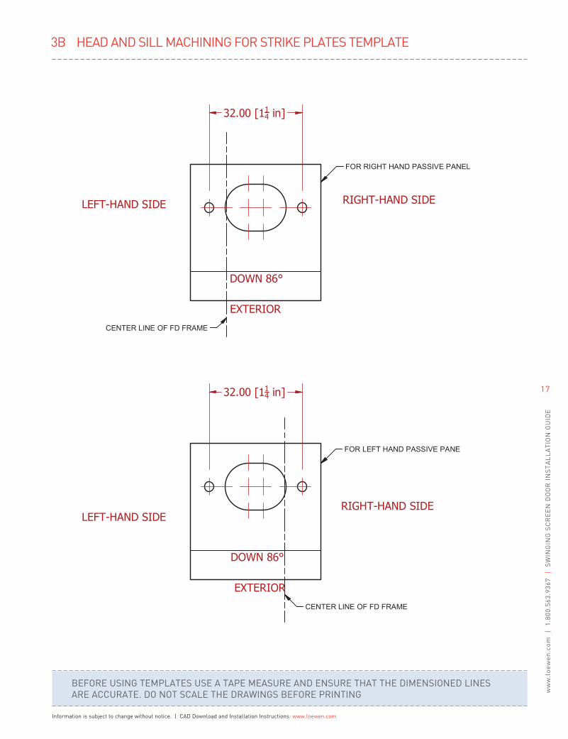
3B HEAD AND SILL MACHINING FOR STRIKE PLATES TEMPLATE
BEFORE USING TEMPLATES USE A TAPE MEASURE AND ENSURE THAT THE DIMENSIONED LINESARE ACCURATE. DO NOT SCALE THE DRAWINGS BEFORE PRINTING
Information is subject to change without notice. | CAD Download and Installation Instructions: www.loewen.com
17
ww
w.l
oew
en.c
om |
1.80
0.56
3.93
67
|S
WIN
GIN
G S
CR
EE
N D
OO
R I
NS
TAL
LA
TIO
N G
UID
E

NOTES
This Page intentionally left blank.

Recycled Paper
Printed in Canada P0000A_0917
Distributed by Loewen Inc. in the USA and C.P. Loewen Enterprises Ltd. in Canada and internationally. Trade Marks owned by C.P. Loewen Enterprises Ltd. Used under license. © C.P. Loewen Enterprises Ltd. All rights reserved.
Information subject to change without notice.
TO FIND YOUR NEAREST LOEWEN DEALER GO TO WWW.LOEWEN.COM OR CONTACT US AT:
E-mail:[email protected]
Canada and U.S.A: 1.800.563.9367
International: 1.204.326.6446
Loewen metal clad products carry the industry’s best warranty, covering paint, glass and wood components for 20 years. Visit loewen.com for complete details.