LHCb RICH1 Engineering Design Review Report Members...
44
LHCb 2004-121 EDMS 493831 29 August 2004 LHCb RICH 1 Engineering Design Review Report Members of the LHCb RICH group University of Bristol, Bristol, UK N.H. Brook, R.D. Head, F. Metlica, A. Muir, A. Phillips, F.F. Wilson University of Cambridge, Cambridge, UK A. Buckley, V. Gibson, K. Harrison, C.R. Jones, S.G. Katvars, C. Lazzeroni, J. Storey, C.P. Ward, S.A. Wotton University of Milano-Bicocca and INFN, Milano, Italy M. Alemi, C. Arnabaldi, T. Bellunato, M. Calvi, C. Matteuzzi, M. Musy, P. Negri, D. Perego, G. Pessina University of Edinburgh, Edinburgh, UK R. Chamonal, S. Eisenhardt, J. Lawrence, J .McCarron, F. Muheim, S. Playfer, A. Walker University of Genoa and INFN, Genoa, Italy S. Cuneo, F. Fontanelli, V. Gracco, G. Mini, P. Musico, A. Petrolini, M. Sannino University of Glasgow, Glasgow, UK A.G. Bates, A. MacGregor, V. O’Shea, C. Parkes, S. Paterson, D. Petrie, A. Pickford, M. Rahman, F.J.P. Soler 1) Imperial College, London, UK L. Allebone, G.J. Barber, W. Cameron, D. Clark, P. Dornan, A. Duane, U. Egede, R.Hallam, A. Howard, R. Plackett, D.R. Price, T. Savidge, G. Vidal-Sitjes, D. Websdale University of Oxford, Oxford, UK M. Adinolfi, J.H. Bibby, C. Cioffi, V. Gligorov, N. Harnew, F. Harris, I.A. McArthur, C. Newby, B. Ottewell, J. Rademacker, R. Senanayake, L. Somerville, A. Soroko, N.J. Smale, S. Topp-Jorgensen, G. Wilkinson, S.Yang University of Paris VI and VII (LPNHE) Paris, France M. Benayoun Institute of High Energy Physics (IHEP-Serphukov), Protvino, Russia V .Khmelnikov, V .Obraztsov Rutherford Appleton Laboratory, Chilton, UK C.J. Densham, S. Easo, B. Franek, G. Kuznetsov, P. Loveridge, D. Morrow, J.V. Morris, A. Papanestis, G.N. Patrick, M.L. Woodward CERN, Geneva, Switzerland G. Aglieri-Rinella, A. Albrecht, A. Braem, M. Campbell, C. D’Ambrosio, R. Forty, C. Frei, T. Gys, O. Jamet, N. Kanaya, M. Losasso, M. Moritz, M. Patel, D. Piedigrossi, W. Snoeys, O. Ullaland, A. van Lysebetten, K. Wyllie, 1) also at Rutherford Appleton Laboratory, Chilton Abstract This document describes the concepts of the engineering design to be adopted for the upstream Ring Imaging Cherenkov detector (RICH 1) of the reoptimized LHCb detector. Our aim is to ensure that coherent solutions for the engineering design and integration for all components of RICH 1 are available, before proceeding with the detailed design of these components.
Transcript of LHCb RICH1 Engineering Design Review Report Members...
LHCb 2004-121EDMS 493831
29 August 2004
LHCb RICH1 Engineering Design Review Report
Members of the LHCb RICH group
University of Bristol, Bristol, UKN.H. Brook, R.D. Head, F. Metlica, A. Muir, A. Phillips, F.F. Wilson
University of Cambridge, Cambridge, UKA. Buckley, V. Gibson, K. Harrison, C.R. Jones, S.G. Katvars, C. Lazzeroni, J. Storey,
C.P. Ward, S.A. WottonUniversity of Milano-Bicocca and INFN, Milano, Italy
M. Alemi, C. Arnabaldi, T. Bellunato, M. Calvi, C. Matteuzzi, M. Musy, P. Negri, D. Perego,G. Pessina
University of Edinburgh, Edinburgh, UKR. Chamonal, S. Eisenhardt, J. Lawrence, J .McCarron, F. Muheim, S. Playfer, A. Walker
University of Genoa and INFN, Genoa, ItalyS. Cuneo, F. Fontanelli, V. Gracco, G. Mini, P. Musico, A. Petrolini, M. Sannino
University of Glasgow, Glasgow, UKA.G. Bates, A. MacGregor, V. O’Shea, C. Parkes, S. Paterson, D. Petrie, A. Pickford,
M. Rahman, F.J.P. Soler1)
Imperial College, London, UKL. Allebone, G.J. Barber, W. Cameron, D. Clark, P. Dornan, A. Duane, U. Egede, R.Hallam,
A. Howard, R. Plackett, D.R. Price, T. Savidge, G. Vidal-Sitjes, D. WebsdaleUniversity of Oxford, Oxford, UK
M. Adinolfi, J.H. Bibby, C. Cioffi, V. Gligorov, N. Harnew, F. Harris, I.A. McArthur,C. Newby, B. Ottewell, J. Rademacker, R. Senanayake, L. Somerville, A. Soroko, N.J. Smale,
S. Topp-Jorgensen, G. Wilkinson, S.YangUniversity of Paris VI and VII (LPNHE) Paris, France
M. BenayounInstitute of High Energy Physics (IHEP-Serphukov), Protvino, Russia
V .Khmelnikov, V .ObraztsovRutherford Appleton Laboratory, Chilton, UK
C.J. Densham, S. Easo, B. Franek, G. Kuznetsov, P. Loveridge, D. Morrow, J.V. Morris,A. Papanestis, G.N. Patrick, M.L. Woodward
CERN, Geneva, SwitzerlandG. Aglieri-Rinella, A. Albrecht, A. Braem, M. Campbell, C. D’Ambrosio, R. Forty, C. Frei,T. Gys, O. Jamet, N. Kanaya, M. Losasso, M. Moritz, M. Patel, D. Piedigrossi, W. Snoeys,
O. Ullaland, A. van Lysebetten, K. Wyllie,
1) also at Rutherford Appleton Laboratory, Chilton
Abstract
This document describes the concepts of the engineering design to be adopted for the upstreamRing Imaging Cherenkov detector (RICH 1) of the reoptimized LHCb detector. Our aim is toensure that coherent solutions for the engineering design and integration for all components ofRICH 1 are available, before proceeding with the detailed design of these components.

Contents
1 Introduction 3
1.1 Evolution since the RICH Technical Design Report . . . . . . . . . . . . . . . . . 5
2 Parameters of the Optical System 5
2.1 Method . . . . . . . . . . . . . . . . . . . . . . . . . . . . . . . . . . . . . . . . . 5
2.2 Constraints . . . . . . . . . . . . . . . . . . . . . . . . . . . . . . . . . . . . . . . 7
2.3 Results . . . . . . . . . . . . . . . . . . . . . . . . . . . . . . . . . . . . . . . . . . 7
3 Magnetic Shield 10
3.1 Requirements . . . . . . . . . . . . . . . . . . . . . . . . . . . . . . . . . . . . . . 10
3.2 Magnetic Modelling . . . . . . . . . . . . . . . . . . . . . . . . . . . . . . . . . . 11
3.3 Mechanical Construction . . . . . . . . . . . . . . . . . . . . . . . . . . . . . . . . 12
4 Gas enclosure 16
4.1 Requirements . . . . . . . . . . . . . . . . . . . . . . . . . . . . . . . . . . . . . . 16
4.2 Mechanics . . . . . . . . . . . . . . . . . . . . . . . . . . . . . . . . . . . . . . . . 17
4.2.1 Structural analysis . . . . . . . . . . . . . . . . . . . . . . . . . . . . . . . 18
4.3 RICH 1 seal to VELO . . . . . . . . . . . . . . . . . . . . . . . . . . . . . . . . . 18
4.4 Exit window and seal to beam pipe . . . . . . . . . . . . . . . . . . . . . . . . . . 19
4.5 Quartz windows . . . . . . . . . . . . . . . . . . . . . . . . . . . . . . . . . . . . 21
5 Optical elements 22
5.1 Spherical Mirrors . . . . . . . . . . . . . . . . . . . . . . . . . . . . . . . . . . . . 22
5.1.1 Structural analysis . . . . . . . . . . . . . . . . . . . . . . . . . . . . . . . 23
5.1.2 Manufacture . . . . . . . . . . . . . . . . . . . . . . . . . . . . . . . . . . 24
5.2 Flat Mirrors . . . . . . . . . . . . . . . . . . . . . . . . . . . . . . . . . . . . . . . 24
5.2.1 Manufacture . . . . . . . . . . . . . . . . . . . . . . . . . . . . . . . . . . 24
5.3 Spherical Mirror Mounts and Adjustment . . . . . . . . . . . . . . . . . . . . . . 25
5.4 Flat Mirror Mounts and Adjustment . . . . . . . . . . . . . . . . . . . . . . . . . 27
5.5 Alignment . . . . . . . . . . . . . . . . . . . . . . . . . . . . . . . . . . . . . . . . 28
6 Photon Detector assembly 29
6.1 Overview . . . . . . . . . . . . . . . . . . . . . . . . . . . . . . . . . . . . . . . . 29
6.2 Design . . . . . . . . . . . . . . . . . . . . . . . . . . . . . . . . . . . . . . . . . . 29

6.3 Services . . . . . . . . . . . . . . . . . . . . . . . . . . . . . . . . . . . . . . . . . 29
6.4 Access and Maintenance . . . . . . . . . . . . . . . . . . . . . . . . . . . . . . . . 31
7 Radiators 32
7.1 Aerogel . . . . . . . . . . . . . . . . . . . . . . . . . . . . . . . . . . . . . . . . . 32
7.2 C4F10 gas . . . . . . . . . . . . . . . . . . . . . . . . . . . . . . . . . . . . . . . . 32
8 Alignment, Monitoring and Control 32
9 Assembly and Installation procedures 33
9.1 Installation sequence and schedule . . . . . . . . . . . . . . . . . . . . . . . . . . 33
9.2 Installation tooling required . . . . . . . . . . . . . . . . . . . . . . . . . . . . . . 35
10 Project planning 35
11 Detailed drawings 40

Figure 1: Reoptimized LHCb detector layout, showing the two RICH detectors. RICH 1 islocated upstream of the LHCb dipole magnet, between the VELO and Trigger Tracker.
1 Introduction
The layout of the LHCb detector is shown in Fig. 1 and described in the Reoptimized DetectorDesign and Performance Technical Design Report (TDR) [1]. Particle identification is providedby two Ring Imaging Cherenkov (RICH) detectors. The basic requirement for the RICH systemis to provide particle identification over a wide momentum range, from 1− ≥ 100 GeV/c. Thetechnical design of the system has been described in TDRs [1, 2] and the engineering designof RICH 2 is described in reference [5]. This report describes the engineering design solutionschosen for the RICH 1 detector. It does not include detailed production engineering drawings;these will be included in the production readiness reviews that precede ordering and manufactureof the component subsystems. The photon detectors are described in an addendum to the RICHTDR [3] and their readout electronics have been the subject of an independent review report [4].
RICH 1 is shown in Fig.1 upstream of the LHCb dipole magnet, between the VELO and TriggerTracker (TT). It contains silica aerogel and fluorobutane (C4F10) gas radiators, providing par-ticle identification from 1 − 60 GeV/c for particles within a polar angle acceptance of 300 mrad(horizontal) and 250 mrad (vertical).
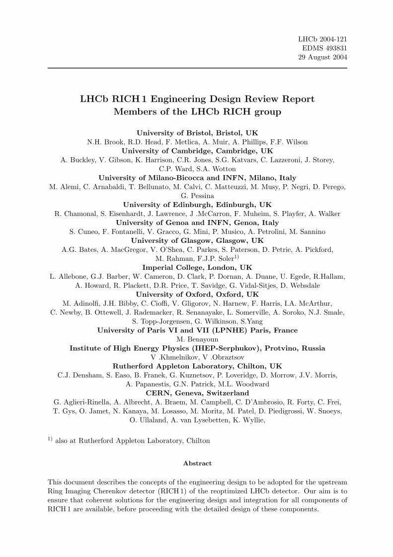
The LHCb coordinate system is right-handed, with origin at the interaction point (IP). Thez-axis follows the beam line which is inclined at +3.6 mrad to the horizontal, the y-axis pointsupwards, orthogonal to the z-axis, and the x-axis is horizontal. RICH 1 is aligned to the LHCbcoordinate axes and is placed within the limits 985 ≤ z ≤ 2170 mm, assigned by the LHCbDetector Geometry Database [6]. The gas Cherenkov radiator, C4F10, has refractive indexn = 1.015 at STP and is operated at atmospheric temperature and pressure. The silica aerogelhas refractive index n = 1.03 and provides positive kaon identification from 2 − 10 GeV/c. TheCherenkov angle as a function of particle momentum is shown for the RICH system radiatorsin Fig. 2. In addition to the particle identification (PID) requirements, other criteria have mo-
3
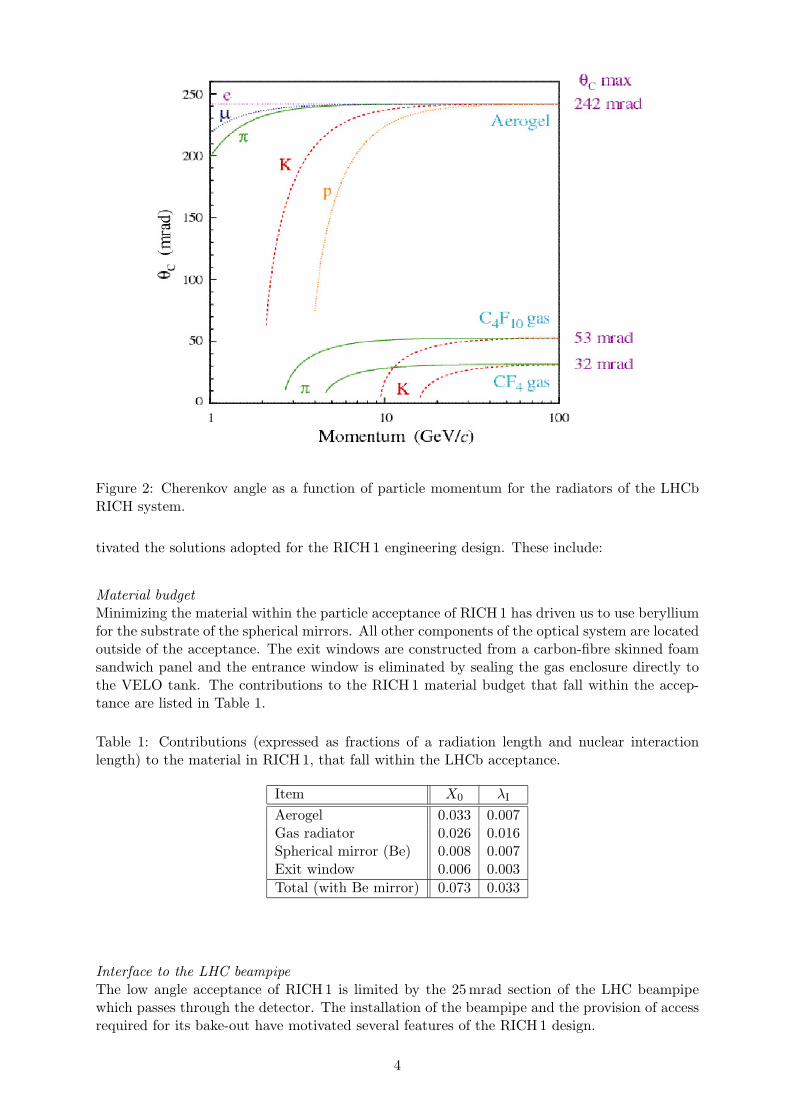
Figure 2: Cherenkov angle as a function of particle momentum for the radiators of the LHCbRICH system.
tivated the solutions adopted for the RICH 1 engineering design. These include:
Material budget
Minimizing the material within the particle acceptance of RICH 1 has driven us to use berylliumfor the substrate of the spherical mirrors. All other components of the optical system are locatedoutside of the acceptance. The exit windows are constructed from a carbon-fibre skinned foamsandwich panel and the entrance window is eliminated by sealing the gas enclosure directly tothe VELO tank. The contributions to the RICH 1 material budget that fall within the accep-tance are listed in Table 1.
Table 1: Contributions (expressed as fractions of a radiation length and nuclear interactionlength) to the material in RICH 1, that fall within the LHCb acceptance.
Item X0 λI
Aerogel 0.033 0.007Gas radiator 0.026 0.016Spherical mirror (Be) 0.008 0.007Exit window 0.006 0.003
Total (with Be mirror) 0.073 0.033
Interface to the LHC beampipe
The low angle acceptance of RICH 1 is limited by the 25 mrad section of the LHC beampipewhich passes through the detector. The installation of the beampipe and the provision of accessrequired for its bake-out have motivated several features of the RICH 1 design.
4

Magnetic shield for photon detectors
The Hybrid photon detectors (HPDs) of the RICH detectors need to be shielded from the fringefield of the LHCb dipole. In the absence of shielding this field is about 60 mT and iron shieldingboxes are required to attenuate the field to a level of 2.5 mT where HPDs can operate withinindividual Mumetal shields. The iron shields are also used to extract flux from the dipoleand focus it into the tracking region where magnetic bending power is required for the Level-1trigger [7].
1.1 Evolution since the RICH Technical Design Report
The overall reoptimization of the LHCb detector has had major consequences on the design ofRICH 1, with respect to that described in the RICH TDR. Most of these changes were addressedin Chapter 4 of the reoptimized TDR [1] but at the time that document was written the multi-anode PMT was the baseline photon detector choice. In the interest of clarity and completenesswe list below the main changes in the RICH 1 design with respect to the RICH TDR.
• Additional plane mirrors (as in RICH 2) are required so that the HPDs can be located ina region where iron magnetic shielding can be used.
• Horizontally-located iron shields would steal the B-field away from where it is required bythe Level-1 trigger, so the HPDs are located above and below the beam where the shieldscan focus the field. Hence the new RICH 1 design employs a vertical optical layout asshown schematically in Fig. 3(a).
• Reduction of the material budget is achieved through the use of beryllium spherical mir-rors with supports and adjustment mechanism outside the spectrometer acceptance. Theentrance window is eliminated by sealing the gas volume directly to the VELO. In Fig. 3(b)a cut-away 3D model of the RICH 1 detector is shown, attached by a gas-tight seal to theVELO tank. The labelling on this figure refers to the components that are described inthe following sections of this report.
2 Parameters of the Optical System
The parameters of the RICH 1 optical layout have been studied with the aid of both GEANT4and stand-alone simulations. The upper and lower halves are symmetric about the plane y = 0,however Cherenkov photons emitted by upward-going charged tracks can be detected in thelower HPDs, so the full acceptance is simulated. There is also reflection symmetry about theplane x = 0, and the mirrors and HPD plane are tilted only in the y − z projection: the centresof curvature of the spherical mirrors and the normals through the centres of the flat mirrors andthe HPD planes therefore all lie in the plane x = 0.
2.1 Method
High momentum charged tracks are simulated, originating from the IP and passing through theactive LHCb acceptance (with polar angles |θx| ≤ 300 mrad, 0 ≤ θy ≤ 250 mrad in the x − zand y − z projections respectively). A uniform distribution of tracks is generated within theselimits.
5

(a)
250 mrad
Track
Beam pipe
Photon Detectors
Aerogel
VELO exit window
Spherical Mirror
Plane Mirror
C4F10
0 100 200 z (cm) (b)
Figure 3: (a) Schematic layout of the RICH 1 detector [Some details in this figure are not up-to-date].(b) Cut-away 3D model of the RICH 1 detector, shown attached by its gas-tight seal to theVELO tank.
Cherenkov photons are generated uniformly along the length of each track within the aerogeland gas radiators, using the appropriate refractive index for photons within the wavelengthacceptance of the HPD photocathodes. The average polar Cherenkov angle is 240 mrad foraerogel and 53 mrad for the C4F10 gas radiator. The azimuthal angle is uniformly distributed.All photons are ray traced, reflecting off the spherical and flat mirrors, and their impact onthe HPD plane is recorded. Photons that strike the LHC beampipe and other obstructions areconsidered to be lost. A typical track and its generated photons is displayed in Fig. 4.
The Cherenkov angle at emission is then reconstructed for each photon in turn, using theprocedure developed for off-line analysis: the HPD impact point is used together with knowledgeof the optics to calculate the Cherenkov angle. For this it is assumed that the emission point ismidway along the corresponding track in the radiator. As the true emission point is randomlydistributed along the track the reconstructed angle will not agree exactly with the true value. Ifthe optical system were configured as an ideal RICH system, then all photons emitted at a givenazimuthal angle would be focused to the same point on the HPD plane. Tilted mirrors result innon-ideal optics and the smearing of the reconstructed Cherenkov angle distribution provides ameasure of the quality of the focusing. Its RMS is referred to as the emission-point error. TheRICH 1 optics is designed such that the emission-point error is not larger than other sources offinite angular resolution, such as the HPD pixel size and the chromatic dispersion due to thevariation in refractive index of the radiator with wavelength. The pixel size of the HPD (2.5 mmat the photocathode) results in a contribution of 0.6 mrad to the Cherenkov angle precision,while chromatic dispersion contributes 0.8(1.6) mrad in the gas(aerogel) radiators. These valuesset the targets for the emission-point error of the optical system.
In addition to the emission-point error, the optical layout determines the required area of cover-age by the HPD plane. In the interest of cost this area should be reduced. In the optimizationprocedure we have required a 100% acceptance for photons emitted by the gas radiator, while acompromise (cost/PID performance) has been accepted for the aerogel photons.
Several constraints from the mechanical construction and magnetic shielding need to be respected
6

Figure 4: GEANT4 display of Cherenkov photons emitted from aerogel and gas radiators by acharged track. The photons are reflected from spherical and plane mirrors, traverse the quartzwindows and strike the HPDs.
as discussed below. The parameters that have been adjusted include: the spherical mirror radius,location of its centre of curvature, location and tilt of the plane mirror and of the HPD plane,as well as the boundaries of these components.
2.2 Constraints
The z-coordinates of the optical elements are constrained by the requirement that RICH 1 fitswithin the envelope assigned to it within the LHCb detector. Space must be allowed for the finitedimensions of the mirrors and their support structures as well as the thicknesses of the magneticshielding, the gas enclosure and the exit window. After accounting for these contributions thereflective suface of the spherical mirror must lie at z ≤ 2085 mm and the reflective surface of theflat mirror must lie at z ≥ 1090 mm.
The tilt of the spherical mirror must ensure that the flat mirror lies outside the particle-acceptance of RICH 1, i.e. y > z tan 0.25. The location of the HPD plane is determined bythe performance of the magnetic shield box. The HPDs must be located within the shield suchthat the maximum field experienced is 2.5 mT. The tilt of the HPD plane is chosen to ensurethat, on average, Cherenkov photons strike the HPDs at close to normal incidence.
2.3 Results
The parameters chosen are listed here, rounded to the nearest mm and mrad. The correspondingcoordinates of the optical components are listed and displayed in Fig. 5.
• The spherical mirrors have radius of curvature 2700 mm with centres of curvature at
7

250mrad
IP
y
z
Figure 5: Half view of the optical geometry in the plane x = 0. Coordinates (y, z in mm) forthe indicated points are:Centre of curvature (837.9, -684.4),Spherical mirror: point 1 (0.0, 1882.3), point 2 (600.0, 2005.1),Plane mirror: point 3 (350.0, 1310.0), point 4 (1100.0, 1118.5),Quartz window: point 5 (1191.1, 1134.51), point 6 (909.5, 1691.7),HPD plane: point 7 (1317.7, 1231.7), point 8 (1187.4, 1482.3), point 9 (1056.7, 1733.8).
x, y, z = 0,±838,−684 mm.Their boundaries in the x − y projection are given by x = ±795 mm, y = 0, 600 mm andsimilarly for the lower (−y) mirror.
• The flat mirrors are tilted at an angle 0.250 rad with respect to the y-axis.Their boundaries in the x − y projection are given by x = ±740 mm, y = 350, 1100 mmand similarly for the lower (−y) mirror.Their horizontal edges that lie closest to the beam line are located at z = 1310 mm.
• The HPD planes are centred at x, y, z = 0, 1187, 1482 mm and tilted at an angle 1.091 radwith respect to the y-axis. They are covered by 7 rows of 14 HPDs, hexagonally closepacked, with centres separated by 91.5mm. This corresponds to an area for the HPDplane of 1327 mm×567 mm, with an active area fraction of 0.61.
With these parameters, the emission-point error is an acceptable value of 0.67 mrad for the gasradiator, and negligible compared with other sources of error for the aerogel. The photon hitdensity distributions at the mirrors and HPD plane are shown in Fig. 6. These show that themirror dimensions given above are more than adequate to ensure that all photons that potentiallyfall within the HPD acceptance can be reflected. The fraction of photons generated by thegas(aerogel) and striking the HPD plane is 100%(68%) and striking an active photocathodeis 61%(42%). The numbers of photoelectrons detected per track has been estimated [1] atNpe = 30(6) for the gas(aerogel) radiators respectively.
8

u/mm
v/m
m(a)
u/mm
v/m
m
(b)
u/mm
v/m
m
(c)
u/mm
v/m
m
(d)
x/mm
y/m
m
(e)
x/mm
y/m
m(f)
x/mm
y/m
m
(g)
x/mm
y/m
m
(h)
-400
-200
0
200
400
-500 0 500-400
-200
0
200
400
-500 0 500
-400
-200
0
200
400
-500 0 500-400
-200
0
200
400
-500 0 500
0
200
400
600
-500 0 500
400600800
1000
-500 0 500
0
200
400
600
-500 0 500
400600800
1000
-500 0 500
Figure 6: Hit density distributions of the impact point of simulated photons on various surfaces,where the area of each box is proportional to the number of photons landing in that region andthe axes refer to coordinates in the LHCb reference system. Only upward-going tracks are usedto generate the Cherenkov photons:(a) Aerogel and (b) C4F10 photon hits on upper HPD plane.(c) Aerogel and (d) C4F10 photon hits on lower HPD photocathodes.(e) Spherical and (f) plane mirror hits for all photons in LHCb acceptance.(g) Spherical and (h) plane mirror hits for photons that hit HPD photocathodes.
Within the constraints of the current design it is possible to move this optical system by 50 mmin z, keeping all other parameters fixed. The final z-location could retain this flexibility untilthe testing of prototype mirror adjustment mechanisms is completed and their detailed designis frozen (Feb 2005).
9
(a) (b)
0 0.05 0.1 0.15 0.2 0.25 0.3 0.35 0.4 0.45 0.550
55
60
65
70
75
80
85
90
95
100
integrated B field (0 < z < 250 cm) [Tm]
0 0.05 0.1 0.15 0.2 0.25 0.3 0.35 0.4 0.45 0.5
rela
tiv
e L
evel
-1 e
ffic
ien
cy [
%]
50
55
60
65
70
75
80
85
90
95
100
Figure 7: (a)Effect of a 3 mT magnetic field on the HPD image; the image of a cross on theanode is shown for no applied field, and then for 3 mT axial and transverse fields. The squareboundary represents the 16 mm×16 mm sensitive area of the pixel sensor, and the largest ob-served translation (about 2.5 mm = 5 pixels) is indicated with an arrow.(b)Dependence of the Level-1 trigger performance on the upstream magnetic bending. Thevertical line corresponds to the field integral used in recent physics performance studies.
3 Magnetic Shield
In the absence of magnetic shielding the HPDs would experience a magnetic field from the LHCbdipole of about 60 mT. HPDs have been tested in both axial and transverse magnetic fields. Thedistortions of the electron optics, primarily a rotation of the image due to the axial component,is shown in Fig. 7(a) for a single HPD, surrounded by a 0.9 mm-thick coaxial Mumetal cylinder,in B-fields of 3 mT, both axial and transverse. Although the distortions need to be corrected(this is described in an addendum to the RICH TDR [3]), there is no loss of the image fromthe active area of the pixellated anode. With an axial field of 5mT there is a loss of about 4%of the photocathode area. A 5 mT transverse field results in no loss. Measurements have beenmade of the field inside an array of Mumetal shields with an external axial field of 5 mT. Theseindicate that the field inside the HPD is equivalent to that seen by a single shielded tube at 3 mT.Transverse fields give small distortions but the array is more difficult to shield due to possiblesaturation of the Mumetal tube array. A preliminary analysis using an array of 0.9 mm-thickMumetal cylinders in the RICH 1 shield indicates that the field inside the cylinders does notexceed 1 mT, while the field in the Mumetal itself is 0.35 T, about one half the saturation value.Until we have experimental confirmation, this risk is mitigated in the current RICH 1 design byallowing space in the HPD assembly for Mumetal shields up to 2mm thick.
The bending of charged particles in the fringe field between the VELO (where the magneticfield must be small) and the TT station is an important requirement in the Level-1 trigger.The degradation of the Level-1 trigger performance as a function of this bending is shown inFig. 7(b), with further details in [7].
3.1 Requirements
The design goal for the iron magnetic shielding boxes has been to reduce the magnetic fieldeverywhere in the plane of the HPDs (Bmax) to < 2.5 mT, while maintaining a field integralalong the z-axis from 0 to 2500 mm (Btrig) of > 0.15 T·m.
The engineering design is constrained by several other factors including the obvious need forspace to accommodate the HPDs and their readout electronics and for an unobstructed light path
10

to the HPDs. The available space envelope must be respected and gravitational and magneticforces must be accommodated in the design. Since the HPD assemblies and the gas enclosureare mounted from the shielding boxes they will need to be mechanically stable at the level of0.5 mm (cf: HPD pixel size of 2.5 mm), to avoid degrading the Cherenkov angular precision. Theassembly of the beampipe to the VELO and the subsequent sealing of the RICH 1 gas enclosureat the VELO exit window requires that the upstream walls cannot approach closer than 550 mmto the beampipe at x = 0, although some shaping around the aperture (teeth) of the circularwindow is possible.
Availability of the raw ARMCO iron (the preferred shielding material) in thicknesses of 50and 100 mm has been taken into account to reduce machining costs. Furthermore, the limitedcraning facilities at the location of RICH 1 have motivated a design of the lowest possible weight.Removable parts are required for access to the HPDs, to the mirror assemblies and to thebeampipe. Bake-out of the beampipe requires removal of the mirror assemblies. Again, limitedcrane facilities dictate that the weight of each removable part should not exceed about one tonne.
3.2 Magnetic Modelling
The shielding has been designed with the aid of the TOSCA/OPERA1 finite element softwarepackage in which the complete LHCb dipole is modelled as well as the shield. This has allowed agood understanding of the effect of varying the design parameters (details can be found in [1]),although absolute values of the fields predicted by the model have not been checked experimen-tally, and will not be until the shields have been manufactured and installed in the B-field ofthe LHCb dipole. The meshing of the model has been varied and indications are that absolutepredictions are stable at the level of 10–20%. One global conclusion from the model is that anychange required to increase the field integral also increases the field inside the shielding. Theresolution of these conflicting goals is only achieved by adding iron extension blocks between theshielding boxes and the LHCb magnet. These collect flux from the magnet, channel it throughthe shield box and the upstream pole directs it where it is needed for the trigger.
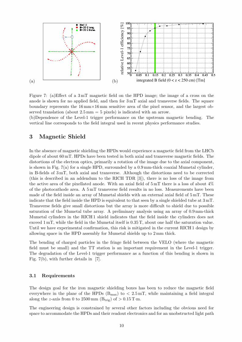
The model, resulting from an iterative optimization procedure, is shown in Fig. 8. The shieldingboxes are constructed from very pure (ARMCO) iron with a high saturation field ∼1.8 T. Theiressential components are illustrated in the figure and comments listed below:
• Top plate: 100 mm thick; if thinner, results in saturation.
• Pole piece: 50 mm-thick upstream plate. Its vertical dimensions are critical to both HPDshielding and bending power. The closer to the beam line the better the magnetic perfor-mance.
• Side plates: 50 mm thick. Need to be removed for access, therefore thin to reduce weight.400 mm×400 mm cut-out for HPD services.
• Teeth: 50 mm thick; improve magnetic performance
• Downstream plate: 50 mm thick; channels fringe field from magnet away from HPDs. Noadvantage if thicker.
• Internal block: 100 mm thick; improves performance of pole piece, enhancing Btrig.
• Shelf: 100 mm thick; reduces aperture of window in front of HPDs, reducing Bmax.
• Extension blocks: 200 mm thick; critical to the trigger field, act as a funnel for magneticflux and channel flux to pole the piece.
11
Figure 8: RICH 1 magnetic shielding boxes.
Results of the magnetic analysis for these shielding boxes are shown in Fig. 9. The maximumfield at the photon detector plane is Bmax=2.6mT and is directed such that the main componentis axial for most HPDs. The integral field Btrig=0.14 T·m. These values are close to the designgoals and represent the best compromise we can achieve for the conflicting requirements. Themagnetic forces on this structure have been calculated by integrating the Maxwell stress tensorover the surface. The horizontal force on each box (towards the magnet) is 35 kN and the verticalcomponent (directed up(down)wards on the upper(lower) box) is 26 kN. These are comparableto the weight (approx 8 tonnes per box) and are accounted for in the mechanical design.
3.3 Mechanical Construction
The mechanical design is required to conform to the components of the shield as described bythe magnetic model. It must also provide the interfaces to other parts of the RICH 1 detectorand provide facilities for its assembly. These include:
• Support to attach upper to lower shielding boxes during installation
• Mounting of lower box to tunnel floor
• Mounting of upper box from cavern wall
• Craning points for removable parts
• Mounting points for HPD assembly support
• Mounting points for gas enclosure
An assembly diagram of the shielding structure is illustrated in Fig. 10. It shows the upper
1Vector Fields plc, Oxford, UK
12

(a) (b)
(c)
Figure 9: Results from the TOSCA magnetic analysis.(a) B-field through the vertical cross section of the shield at x = 0. The magnet coils are closeto the top right-hand corner of the box, from where flux is channelled via the extension blockthrough the top of the shielding box and down the upstream pole. The arrows indicate thedirection of the field, its magnitude is indicated by the colour-coding.(b) B-field along the beam line.(c) Inside the box the HPDs experience a field whose main component is axial. The plot showsthe magnitude (in gauss) of the B-field at the HPD plane.
box supported from the lower using four vertical beams. In this configuration the shield willbe transported to its location in LHCb. The lower box is fixed to an adjustable mount on thetunnel floor (400 mm of concrete has already been cut away from the floor to accommodate theRICH1 shielding design as described), where it is positioned with a precision of order 1 mm.The upper box is then fixed to the cavern wall. The support beams are then removed.
Both boxes are assembled from 50 mm and 100 mm-thick plates of ARMCO iron. The maindimensions can be extracted from the coordinates tabulated in Table 2 together with Fig. 11.The weight of each box is approximately eight tonnes. The side walls are removable to allowaccess to the the HPD assemblies and to the gas enclosure. Craning points are provided tolower(raise) the side walls of the upper(lower) box, while the services (cooling and cables) of theHPDs remain connected. The HPD assemblies are mounted within the boxes from rails thatallow travel in the x-direction for maintenance. Figure 12(a) shows the upper module to illustratethe concept. The upstream rail provides the reference positioning, while the downstream railprovides a constraint only in the y-direction. The support points are shown in Fig. 12(b). The
13
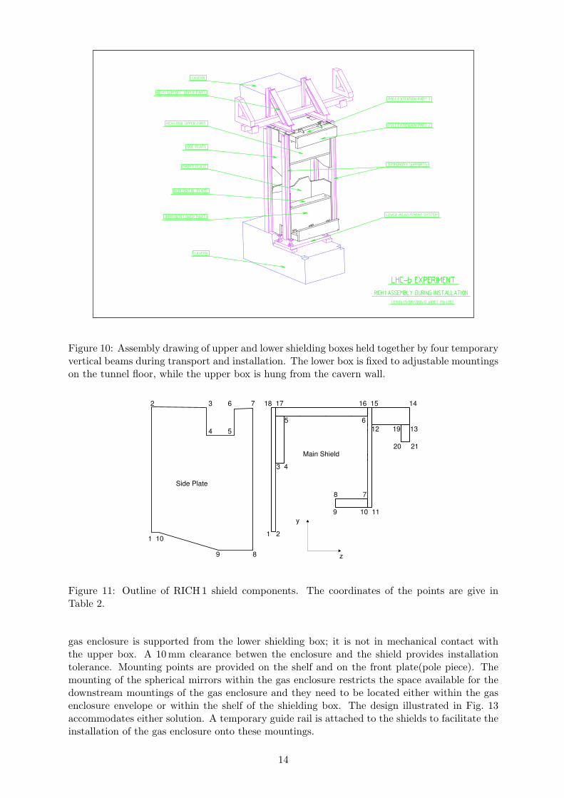
Figure 10: Assembly drawing of upper and lower shielding boxes held together by four temporaryvertical beams during transport and installation. The lower box is fixed to adjustable mountingson the tunnel floor, while the upper box is hung from the cavern wall.
y
z
1 2
3 4
5 6
8 7
9 10 11
12 19 13
20 21
18 17 16 15 14
1 10
9 8
4 5
2 3 6 7
Side Plate
Main Shield
Figure 11: Outline of RICH 1 shield components. The coordinates of the points are give inTable 2.
gas enclosure is supported from the lower shielding box; it is not in mechanical contact withthe upper box. A 10 mm clearance betwen the enclosure and the shield provides installationtolerance. Mounting points are provided on the shelf and on the front plate(pole piece). Themounting of the spherical mirrors within the gas enclosure restricts the space available for thedownstream mountings of the gas enclosure and they need to be located either within the gasenclosure envelope or within the shelf of the shielding box. The design illustrated in Fig. 13accommodates either solution. A temporary guide rail is attached to the shields to facilitate theinstallation of the gas enclosure onto these mountings.
14
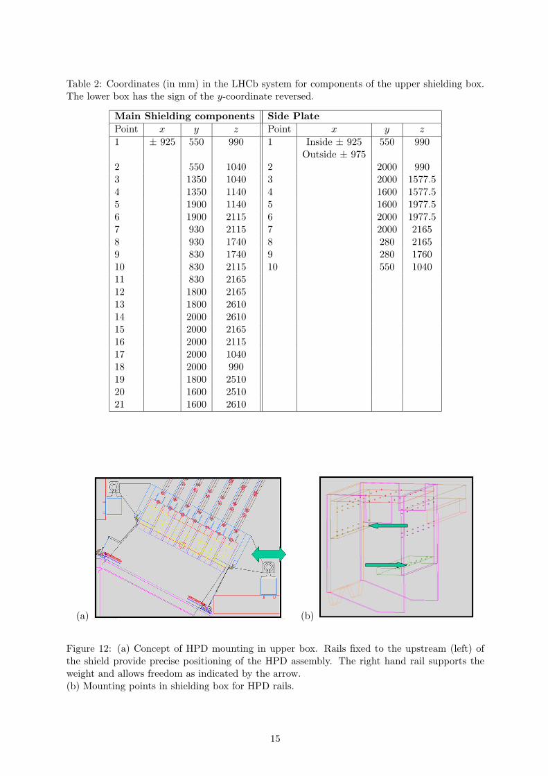
Table 2: Coordinates (in mm) in the LHCb system for components of the upper shielding box.The lower box has the sign of the y-coordinate reversed.
Main Shielding components Side Plate
Point x y z Point x y z
1 ± 925 550 990 1 Inside ± 925 550 990Outside ± 975
2 550 1040 2 2000 9903 1350 1040 3 2000 1577.54 1350 1140 4 1600 1577.55 1900 1140 5 1600 1977.56 1900 2115 6 2000 1977.57 930 2115 7 2000 21658 930 1740 8 280 21659 830 1740 9 280 176010 830 2115 10 550 104011 830 216512 1800 216513 1800 261014 2000 261015 2000 216516 2000 211517 2000 104018 2000 99019 1800 251020 1600 251021 1600 2610
(a) (b)
Figure 12: (a) Concept of HPD mounting in upper box. Rails fixed to the upstream (left) ofthe shield provide precise positioning of the HPD assembly. The right hand rail supports theweight and allows freedom as indicated by the arrow.(b) Mounting points in shielding box for HPD rails.
15
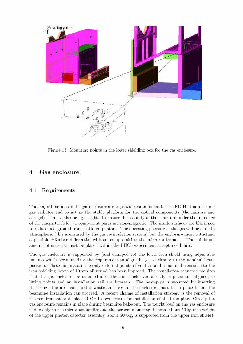
Figure 13: Mounting points in the lower shielding box for the gas enclosure.
4 Gas enclosure
4.1 Requirements
The major functions of the gas enclosure are to provide containment for the RICH 1 fluorocarbongas radiator and to act as the stable platform for the optical components (the mirrors andaerogel). It must also be light tight. To ensure the stability of the structure under the influenceof the magnetic field, all component parts are non-magnetic. The inside surfaces are blackenedto reduce background from scattered photons. The operating pressure of the gas will be close toatmospheric (this is ensured by the gas recirculation system) but the enclosure must withstanda possible ±3 mbar differential without compromising the mirror alignment. The minimumamount of material must be placed within the LHCb experiment acceptance limits.
The gas enclosure is supported by (and clamped to) the lower iron shield using adjustablemounts which accommodate the requirement to align the gas enclosure to the nominal beamposition. These mounts are the only external points of contact and a nominal clearance to theiron shielding boxes of 10 mm all round has been imposed. The installation sequence requiresthat the gas enclosure be installed after the iron shields are already in place and aligned, solifting points and an installation rail are foreseen. The beampipe is mounted by insertingit through the upstream and downstream faces so the enclosure must be in place before thebeampipe installation can proceed. A recent change of installation strategy is the removal ofthe requirement to displace RICH 1 downstream for installation of the beampipe. Clearly thegas enclosure remains in place during beampipe bake-out. The weight load on the gas enclosureis due only to the mirror assemblies and the aerogel mounting, in total about 50 kg (the weightof the upper photon detector assembly, about 500 kg, is supported from the upper iron shield).
16

Figure 14: The gas enclosure, a monocoque construction manufactured from welded panels of30 mm-thick aluminium tooling plate.
4.2 Mechanics
The gas enclosure is essentially a six-sided box (Fig.14) with each face closed by componentshaving very different requirements:
• The upstream face is closed by an element which maintains the gas and light seal betweenthe enclosure and the VELO exit face. This structure must also ensure that minimal forceis exerted on the VELO and the upstream wall of the enclosure and that manufacturingand alignment tolerances (and changes due to temperature) can be accommodated.
• The top and bottom faces are closed by quartz windows that allow Cherenkov photons topass through to the photon detectors mounted behind.
• The downstream face accommodates the low-mass exit window which is sealed to a flangeon the beryllium beampipe.
• The side faces are closed by panels that are designed to maximize the access for installationof the internal optical components and the beampipe.
Recently it has been shown that the original frame-and-skin design of this box can be replacedwith a design where each face of the structure is machined from 30 mm-thick aluminium-alloytooling plate2 which is then welded at the edges to form the enclosure. Although materialcosts of such an approach are higher, all necessary mounting, sealing and welding featurescan be machined into the plate at essentially a fixed cost. The weight of the gas enclosure isapproximately 500 kg.
The dimensions of the entrance and exit windows are dictated primarily by the LHCb acceptancelimits but the installation sequence imposes its own constraints. The VELO exit window, whichis integral with the beampipe, must be able to pass through the gas enclosure entrance window,as must its clamping flange which is a complete ring. Both of these are able to pass throughthe gas enclosure seal to the VELO to allow for the possibility that this latter component is
26061-T651
17
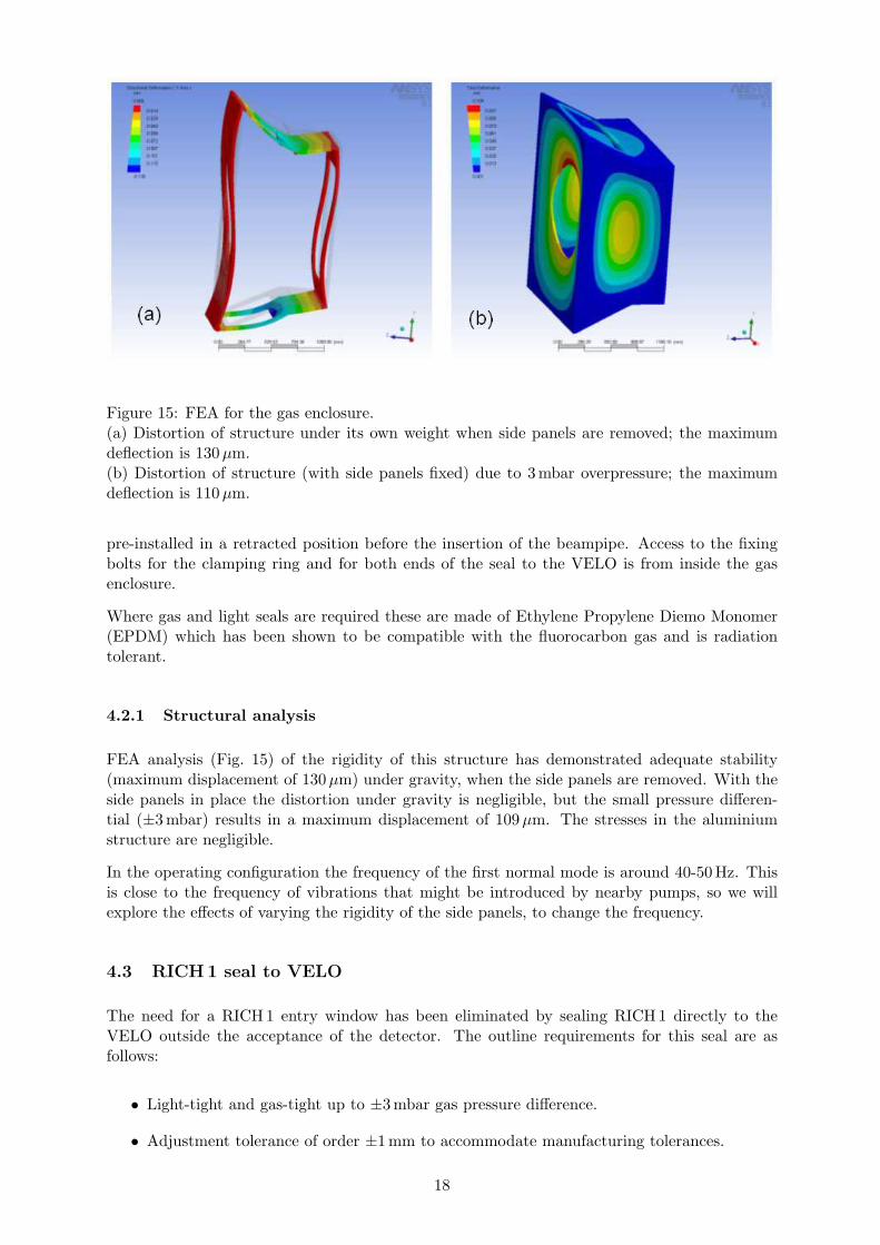
Figure 15: FEA for the gas enclosure.(a) Distortion of structure under its own weight when side panels are removed; the maximumdeflection is 130 µm.(b) Distortion of structure (with side panels fixed) due to 3 mbar overpressure; the maximumdeflection is 110 µm.
pre-installed in a retracted position before the insertion of the beampipe. Access to the fixingbolts for the clamping ring and for both ends of the seal to the VELO is from inside the gasenclosure.
Where gas and light seals are required these are made of Ethylene Propylene Diemo Monomer(EPDM) which has been shown to be compatible with the fluorocarbon gas and is radiationtolerant.
4.2.1 Structural analysis
FEA analysis (Fig. 15) of the rigidity of this structure has demonstrated adequate stability(maximum displacement of 130 µm) under gravity, when the side panels are removed. With theside panels in place the distortion under gravity is negligible, but the small pressure differen-tial (±3 mbar) results in a maximum displacement of 109µm. The stresses in the aluminiumstructure are negligible.
In the operating configuration the frequency of the first normal mode is around 40-50 Hz. Thisis close to the frequency of vibrations that might be introduced by nearby pumps, so we willexplore the effects of varying the rigidity of the side panels, to change the frequency.
4.3 RICH1 seal to VELO
The need for a RICH 1 entry window has been eliminated by sealing RICH 1 directly to theVELO outside the acceptance of the detector. The outline requirements for this seal are asfollows:
• Light-tight and gas-tight up to ±3 mbar gas pressure difference.
• Adjustment tolerance of order ±1 mm to accommodate manufacturing tolerances.
18

Figure 16: RICH 1 seal to VELO.
• Compliance of order ±1 mm to allow thermal, pressure and vibration movements withoutgenerating significant forces on RICH 1 or the VELO.
• Entire assembly to be non-magnetic, radiation tolerant, compatible with C4F10, and shouldallow RICH 1 and VELO to be electrically isolated.
• Access to both sides of seal to be possible from inside the gas enclosure.
An outline design for this seal is shown in Fig. 16; the drawings in Fig. 31 and Fig. 32 . Itcomprises a tube, an adjustable collar and a clamp ring, with a compressible EPDM foamedrubber seal providing the necessary compliance. The inner tube is fitted and sealed to theVELO flange. The adjustable collar slides over this and is sealed to it with a sliding O-ringallowing for any set-up error or movement in z. This will also permit small movements in x andy between the VELO and RICH 1 during operation, with a load of 25 kg resulting from 1 mm(the operational stability requirement of the RICH 1 structure is below 0.5 mm) movement ofa medium-density foamed seal. The adjustable collar is sealed to RICH 1 with another O-ringand a sliding clamp ring permitting a small x and y misalignment. When fully assembled theloading on both RICH 1 and VELO is nominally zero.
4.4 Exit window and seal to beam pipe
The exit window is a low-mass composite panel made from two 0.5 mm-thick carbon-fibre-reinforced epoxy skins separated by 16 mm thick polymethacrylimide (PMI) foam. Each skin ismade from two layers of balanced-weave laminate, with fibres orientated to give 0◦/90◦ in onelayer overlapped with ±45◦ in the other layer. This is in order to generate skins with as closeto uniform a stiffness in the plane as possible. The window is to be attached to a flange on thedownstream face of the RICH 1 gas enclosure using a clamping arrangement (Fig. 17(b)) thatallows for positional adjustment in the x and y directions during assembly. The seal betweenthe window and gas enclosure is made using an EPDM rubber sealing strip. The seal to thebeampipe (Fig. 17(a)) uses a compliant annular Kapton film, which has been designed to isolatethe window from the beampipe both mechanically and electrically. At the outer edge the Kaptonfilm will be sandwiched between the skins of the window and at the inner edge it will be bondedto a disk on the beampipe using carbon-fibre rings. The assembly drawing for these components
19

Figure 17: (a) Flexible Kapton seal to the beam pipe, (b) Clamping and adjustment detail.
Table 3: Radiation length of the RICH 1 exit window.
Material Thickness (mm) X0 (mm) %X0
CFRP Laminate 1.0 284 0.35
Rohacell 5 IG 16.0 7954 0.20
Epoxy glue 0.4 357 0.11
Total 0.66
is shown in Fig. 33. The methods and procedures were approved at the engineering design review[9] for the LHCb vacuum pipe.
The radiation length of each of the component materials was calculated based on the chemicalcomposition [8]. A breakdown of the calculated radiation length (%X0) for the RICH 1 exitwindow is given in Table 3. The figures for the carbon-fibre material are based on the resultsfrom a composition analysis of woven pre-cured laminate samples, carried out at RAL. A densityof 52 kg m−3 was assumed for the PMI foam material, and the epoxy glue figures were based onthe RICH 2 epoxy/hardener mix. A one-quarter symmetry model of the RICH 1 exit window wascreated in ANSYS (Fig. 18) using layered-shell elements. An element formulation specificallydesigned for modelling sandwich panels was used, which assumes that all of the transverse shearis carried by the core, and that the skins carry none. The material property data used for thecarbon-fibre skins was based on the results from a testing programme carried out at RAL. Allother properties were taken from manufacturer’s data. The window deflection (in z) due to aninternal relative gas pressure of 1000 Pa was calculated. This represents a factor of safety of threeon the maximum working overpressure stated for the gas containment. At 300 Pa overpressurethe deflection results in an axial load of 0.4 kg on the beampipe. A space optimization, shown inFig. 19, was carried out in order to determine the core thickness associated with the minimumz envelope requirement, which was defined as the thickness of the window plus its deflectionin either direction (t + 2δz). The optimum core thickness was found to be 16 mm, where themaximum deflection of the window (in z) was 4.3mm, and factors of safety on stress of 8.8, 18.4,and 15.8 were calculated for the carbon-fibre skins, foam core, and aluminium window framerespectively. Results obtained using this method of analysis compare favourably with test dataobtained from a 2 m x 2 m prototype panel that was manufactured and tested at RAL.
20

Figure 18: ANSYS model of the RICH 1 exit window.(a) Contour plot showing deflection of the window (m) due to an internal relative gas pressureof 1000 Pa. The maximum deflection is 4.3 mm.(b) Detail view of one-quarter symmetry mesh.
Figure 19: Core thickness optimisation for the RICH1 exit window.
4.5 Quartz windows
The Cherenkov light directed towards the photon detectors must traverse quartz windows ap-proximately 1380 mm×620 mm in area, and 6 mm thick, mounted at the top and bottom of thegas enclosure parallel with the photon detector plane. These form part of the radiator gas con-tainment but offer maximum transparency over the wavelength range of the HPD photocatodesensitivity (200–600 nm). Constraints due to the size of the evaporation plant used to depositthe anti-reflective coating dictate that the windows be constructed from two “panes” of quartz,bonded into a window frame which can be mounted on the gas enclosure with the EPDM seal.The central seam includes a narrow non-magnetic support section, either a T-section integralwith the aluminium frame or a separate I-section, which will be of minimal cross section toreduce the shadow on the photon detector plane.
21

Figure 20: Quartz windows and seal.
A single layer of MgF2 dielectric anti-reflection coating on a fused silica substrate reduces sur-face reflectance to under 1.5% per surface over a broad spectral band. A multi-layer coating,optimized for the aerogel Cherenkov light, will be deposited.
A further light and gas-tight seal is provided on the photon detector side of the quartz windowsin order to maintain the dark, nitrogen-filled environment required for the HPDs. This takesthe form of a detachable skirt sealed to the HPD assembly, which can be clamped around thewindow frame. The quartz windows will only be installed along with the other delicate opticalcomponents and the apertures will be filled with acrylic or blanking plates during installationand testing. Provision will also be made for the insertion of protective covers when access tothe inside of the gas enclosure is required. The quartz windows and seals are shown in Fig.20.
5 Optical elements
5.1 Spherical Mirrors
Cherenkov light is focused onto the photon detector planes using tilted spherical mirrors and asecondary plane of flat mirrors, as shown in Fig.5. The RICH 1 spherical mirrors have a radiusof curvature of 2700 mm. The mirror surface is segmented into four rectangular quadrants witha footprint in the x − y projection of the detector system of 795 mm×600 mm. Each quadrantis further segmented and consists of two mirrors. Each of the eight mirrors can be individuallyadjusted in angle so that the upper and lower segments share a common centre of curvature.The layout of the spherical mirrors is illustrated in Fig. 21. The inner mirrors have a cut-outto accommodate the beampipe. The clearance from the beampipe is yet to be agreed with thebeampipe group, but 5 mm is the preferred value. At the time of the LHCb re-optimisationTDR two technologies were under consideration for the spherical mirrors: a carbon-fibre epoxyor glass-coated Beryllium. Due to concerns with regards the long-term stability of the epoxymirrors in a fluorocarbon environment, the beryllium option has been adopted.
The baseline solution, outlined in the re-optimisation TDR, was to use mirrors composed of acarbon-fibre cyanate-ester-resin material base3 with an aluminium reflective surface and siliconprotective coating. The optical characteristics of a quarter-sized spherical mirror prototypehad been examined and found to be within the LHCb figures of merit required for radius ofcurvature and angular resolution. In addition the reflectivity of a small sample plane mirror
3Developed and producd by Composite Mirror Applications Inc, Tucson, USA.
22

Figure 21: Be Mirror array as viewed from the rear.
had been measured. The reflectivity was found to be approaching the required figure of meritof 90% in the wavelength range of interest (200 nm < λ <600 nm) and for the required anglesof incidence. With additional tuning of the protective coating material and thickness the figureof merit could be achieved.
An outstanding concern at the time of the re-optimised detector TDR was the suitability ofthe carbon-fibre composite mirror technology for use in a saturated fluorocarbon environment.The sample plane mirror has subsequently been exposed to a fluorocarbon environment over aneleven-month period. A loss in reflectivity was observed over the period of exposure. This losshas been attributed to carbon fibres from the mirror substrate coming through the aluminiumreflective surface; a processes known as print through. This degradation of the mirror is greaterthan what is acceptable for use in the RICH 1 sub-detector. In addition, the quarter-sizedspherical mirror prototype demonstrated a degradation of angular resolution. This degradationoccurred with time and in particular with the extra stress placed on the mirror due to theaddition of the mirror-to-mirror support mechanical interface cups. The loss of angular resolutionexceeded the RICH 1 figure of merit4 of D0 <2.5mm. In contrast, a 6 mm-thick berylliumprototype mirror, approximately one half the size required for RICH 1, provided a value ofD0 < 1 mm that was stable over time.
5.1.1 Structural analysis
A finite element analysis of a 3 mm-thick beryllium mirror has been performed [10]. The latestRICH 1 Outer-Mirror design was analysed using ANSYS, paying particular attention to theway in which it will be supported within the detector. Distortions in the spherical mirrorsurface due to gravity were calculated under a number of support scenarios, using both singlepin and two pin mechanisms. In addition, an investigation was made into the stresses anddisplacements induced in the mirror by preloaded support screws (single point support scheme),thermal expansion (two point support scheme), and misalignment of the mating surfaces atthe supports (two point support scheme). The results suggest that compression of the mirrorrim due to preloaded support screws is unlikely to cause any significant deformation of themirror surface. For a double pin support system, careful design would be required to minimisedistortions in the mirror due to the misalignment of mating surfaces in the mirror supports,though those caused by a differential thermal expansion between the beryllium mirror and steel
4D0 is the diameter of a circular aperture, at the mirror centre of curvature(CoC), in which 95% of light
reflected from a point source at the CoC is contained. A D0 of 2.5 mm corresponds to an RMS Cherenkov-angleprecision of 0.23 mrad for the RICH1 spherical mirrors.
23

support structure are tolerable. Given this additional complication a single pin mechanism hasbeen adopted.
Using the surface displacements of the mirror calculated by the FEA, a calculation of the changeof the coordinates of the centre of curvature from elemental areas on the mirror surface wascalculated by a fitting procedure; this change would be reflected in the final D0 measurementof the mirror. Results are shown in Fig. 22. A single-pin mount, with a diameter of 10 mm,with zero protrusion beyond the rim of the mirror, gave a maximum deflection on the surface of174 µm; this compares to the best-case scenario, when the full edge of the flange is supported, of83 µm. The mean shift in the x-direction of the centre of curvature was ∼ 20 µm with an RMSof ∼ 120 µm. The changes in the y-direction were larger with a mean shift of ∼ 700 µm with anRMS of ∼ 250 µm (corresponding to a D0 of 2 mm) but still within the tolerances required forRICH 1.
5.1.2 Manufacture
The beryllium-glass mirrors are to be produced by the Russian company Kompozit5 (the sameas has manufactured the LHCb beryllium beampipe). Dish-shaped beryllium blanks, 800 mmdiameter and 20 mm thick, are produced by the mining company and sent to Kompozit formachining, grinding and an oxidation process to seal all exposed beryllium surfaces; the glasscoating will be performed by the Vavilov State Optical Institute in St Petersburg. A contracthas already been placed with Kompozit (June 2004) for the production of a prototype berylliummirror, which should be delivered by October 2004. This mirror corresponds to the requireddimensions of one of the outer RICH 1 mirrors, as shown in Fig. 23(a). The beryllium substrateis 3 mm thick and the glass coating is 0.3mm. The optical characteristics of this prototypewill be tested at CERN, and if the tests are satisfactory it will be used in RICH 1. A contractfor the remaining seven beryllium mirrors has been prepared for submission to the ISTC6.Production at Kompozit of the seven mirrors will begin as soon as the prototype has beenverified. IHEP(Protvino), acts as an intermediary, in accordance with the ISTC rules. Theestimated time for production is about 12 months.
5.2 Flat Mirrors
The flat mirrors are of a similar type to those used in the RICH 2 detector. The requirements onthe RICH 2 optical designs are more stringent than those of RICH 1 and are therefore compatible.
To cover the flat mirror surface, 16 rectangular mirrors will be used. There will be four pan-els, one per quadrant, each with four planar mirrors, two mounted above and two below thebeampipe. Each quadrant forms a flat mirror. All 16 individual mirrors have the same nominaldimensions of 370 mm (horizontal)×387 mm, and consist of 6 mm-thick Simax glass (borosili-cate glass by Sklarny Kavalier). As with the spherical mirrors, there will be a 3 mm clearancebetween side-to-side mirror segments, resulting in a loss in active reflective surface coverage ofabout 1.5%.
5.2.1 Manufacture
The Czech company, COMPAS7, is well qualified to produce the flat mirrors. The same com-pany is producing the mirrors for RICH 2 (60 spherical and 40 flat). Once the RICH 2 mirror
5Kompozit, Moscow (http://www.korolev.ru/english/e kompozit.html).6International Science and Technology Centre (http://www.istc.ru).7COMPAS, Research and Development Consortium, Turnov, Czech Republic.
24

(c)
Figure 22: (a) The deflection contour plot from the FEA analysis. The mirror was supportedby a single 10 mm pin, (b) The mesh used in the model.(c) The distribution of the coordinates (in mm) of the centre of curvature of elements of themirror surface.
production is completed, which is probably by the end of 2004, the RICH 1 16 flat mirror pro-duction can begin. Exactly the same production method as for the RICH 2 flat mirrors can beused for the RICH 1 flat mirrors. The timescale for production of the 16 mirrors is about 3months. The call for tender is foreseen to be sent out in October 2004 and production wouldbegin by February 2005. The 16 flat mirrors would be ready by end of April 2005.
5.3 Spherical Mirror Mounts and Adjustment
The angular resolution of the RICH 1 detector depends on the alignment of its optical compo-nents. To ensure that the precision in reconstruction of the Cherenkov angle, about 1.3 mrad inthe gas radiator, is not degraded by uncertainties in alignment the aim is to maintain alignment
25

(a) (b)
Figure 23: (a) An outer beryllium mirror, viewed from the rear.(b) Titanium bushes, inserted into the rim, receive the pins that fix the spherical mirror to itsadjustment mechanism. Only the central pin is used to fix the mirror, the outer pins preventrotation about the central pin.
stability below 0.3mrad. The support design also isolates the mirror from thermal expansionthat may otherwise lead to deformation of the mirror profile.
There are eight spherical beryllium mirrors arranged in pairs to form four quadrants. Eachquadrant forms a spherical mirror surface (795 mm×600 mm) that can be individually adjusted.The four quadrants are centred on the beampipe. Each mirror is fixed at its 20 mm-thick rim toan L-shaped plate at a central fixed point. Safety requirements preclude any fixing direct to theberyllium so titanium bushes will be inserted in the beryllium, bonded using a radiation-hardglue into holes in the mirror rim, as illustrated in Fig. 23. There is a pin (or pins either end)at the side of the rim as a safety mechanism, to prevent the mirror from rotating about thecentral fixed-point in case of accidental shocks. The upper mirrors are supported from the top,the lower mirrors have the same but inverted arrangement, therefore are supported from thebottom. The central bushes receive a bolt (or guiding pin) that fixes the mirror to its supportframe. A retaining washer in conjunction with the bolt will be used on the inside edge of the rimto ensure the mirror cannot fall or touch the beampipe in the (unlikely) event of poor adherenceof the glued bush.
The individual mirror support/adjustment system consists of L-shaped support frames witheach quadrant pair of mirrors mounted to a sub frame, which is fixed to the gas enclosure. TheL-shaped plates are positioned with the two vertical sides furthest from the beamline, henceoutside the detector acceptance. The three adjustable mounts are screwed onto the L-shapedinterface plate in the positions shown in Fig. 24. Three threaded spindles are fixed externally atone end by threaded inserts and at the other end terminate at ball joints in the mounts on theL-shaped interface plate. By rotating one or more of the three threaded spindles it is possibleto adjust the inclination of the L-shaped interface plates about the horizontal, vertical and onediagonal axis. One of the mounts is fixed in position, while the other two mounts are fitted withsliders. One slider allows motion in the plane of the mirror, the third mount has a degree offreedom in the horizontal axis. The sliders provide the overall mechanism with the ability toisolate the supported mirror from thermal expansion of the gas enclosure.
The long-term stability and adjustment characteristics of the prototype aluminium sphericalmirror support have been evaluated. As described in the re-optimisation TDR the relationship
26

Figure 24: Schematic of the L-shape mirror support frame.
(a) (b)
Figure 25: (a) Vertical and (b) horizontal stability measurements of the prototype sphericalmirror support over 700 hours.
between mirror tilt and screw-turn is linear. A tilt change of 0.56 mrad corresponds to a screwturn of 36◦, which enables a sufficiently precise adjustment. In Fig. 25 the stability of theprototype spherical mirror support over a 700 hour period is shown. In the vertical and thehorizontal axes there are fluctuations with a 24 hour period. The range of the vertical tilt islarger than for the horizontal tilt, possibly due to the effects of gravity. The range of the tiltin the horizontal and vertical axes is well below the required 0.3 mrad for RICH 1 requirements.The measurements were taken in a temperature-controlled environment, with a temperaturerange of 2◦C. Further investigations of the support of the mirror support under larger range oftemperature fluctuation, 15◦C, have been undertaken. The vertical tilt varied over 0.25 mradwhilst the horizontal range was slightly greater than 0.1mrad. It is expected that this willbe reduced with an L-shaped support manufactured from stainless steel, with a lower thermalexpansion coefficient. The individual L-shaped mounts for each mirror pair in a particularquadrant are mounted to another intermediate frame (again L-shaped) which is attached to theroof(floor) and sides of the gas enclosure.
5.4 Flat Mirror Mounts and Adjustment
The RICH 1 flat mirrors are outside the LHCb acceptance, so lightweight components are nota requirement. The flat mirrors are of a similar type to those used in the RICH 2 detector andthe requirements on the RICH 2 optical designs are more stringent than those of RICH 1. Tothat end it is proposed to adopt the mirror support of RICH 2. Each mirror segment is fixed on
27
(a) (b)
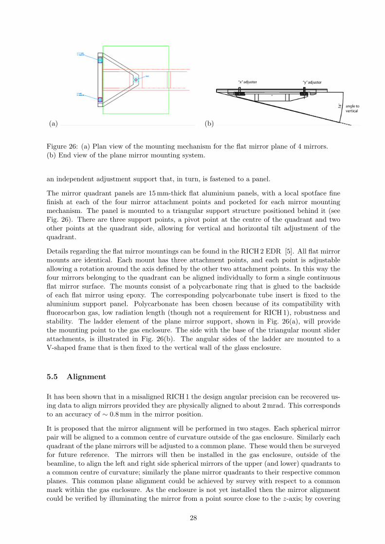
Figure 26: (a) Plan view of the mounting mechanism for the flat mirror plane of 4 mirrors.(b) End view of the plane mirror mounting system.
an independent adjustment support that, in turn, is fastened to a panel.
The mirror quadrant panels are 15 mm-thick flat aluminium panels, with a local spotface finefinish at each of the four mirror attachment points and pocketed for each mirror mountingmechanism. The panel is mounted to a triangular support structure positioned behind it (seeFig. 26). There are three support points, a pivot point at the centre of the quadrant and twoother points at the quadrant side, allowing for vertical and horizontal tilt adjustment of thequadrant.
Details regarding the flat mirror mountings can be found in the RICH 2 EDR [5]. All flat mirrormounts are identical. Each mount has three attachment points, and each point is adjustableallowing a rotation around the axis defined by the other two attachment points. In this way thefour mirrors belonging to the quadrant can be aligned individually to form a single continuousflat mirror surface. The mounts consist of a polycarbonate ring that is glued to the backsideof each flat mirror using epoxy. The corresponding polycarbonate tube insert is fixed to thealuminium support panel. Polycarbonate has been chosen because of its compatibility withfluorocarbon gas, low radiation length (though not a requirement for RICH 1), robustness andstability. The ladder element of the plane mirror support, shown in Fig. 26(a), will providethe mounting point to the gas enclosure. The side with the base of the triangular mount sliderattachments, is illustrated in Fig. 26(b). The angular sides of the ladder are mounted to aV-shaped frame that is then fixed to the vertical wall of the glass enclosure.
5.5 Alignment
It has been shown that in a misaligned RICH 1 the design angular precision can be recovered us-ing data to align mirrors provided they are physically aligned to about 2 mrad. This correspondsto an accuracy of ∼ 0.8 mm in the mirror position.
It is proposed that the mirror alignment will be performed in two stages. Each spherical mirrorpair will be aligned to a common centre of curvature outside of the gas enclosure. Similarly eachquadrant of the plane mirrors will be adjusted to a common plane. These would then be surveyedfor future reference. The mirrors will then be installed in the gas enclosure, outside of thebeamline, to align the left and right side spherical mirrors of the upper (and lower) quadrants toa common centre of curvature; similarly the plane mirror quadrants to their respective commonplanes. This common plane alignment could be achieved by survey with respect to a commonmark within the gas enclosure. As the enclosure is not yet installed then the mirror alignmentcould be verified by illuminating the mirror from a point source close to the z-axis; by covering
28

each half (left/right) it should be possible to align the left and right halves to the same point onthe HPD plane. Once the gas enclosure is installed in the beam line the mirrors are re-mountedusing the survey marks.
6 Photon Detector assembly
6.1 Overview
The RICH 1 HPD assembly is essentially a copy of the RICH 2 design [5][11]. The mounting ofthe HPDs and their Mumetal shields, the coupling of the HPDs to the Level-0 readout cards, thecircuit boards themselves, their mechanical mounting and their cooling mechanics are identical.The size of the RICH 1 shielding has been chosen to accommodate this design. Differences inthe design of the RICH 1 HPD assembly are:
• The number of HPDs is different: 9 columns of 16 HPDs in RICH 2, compared with 7columns of 14 HPDs in RICH 1.
• The maximum centre-to-centre pitch of the HPDs is 89.5 mm in RICH 2, compared with91.5 mm in RICH 1. This is to allow the use of 2 mm-thick Mumetal shields if required.
• The routing of the pipes that pass the C6F14 coolant through the cooling plates will beadapted to the RICH 1 HPD nitrogen enclosure.
• The patch panels for cables and services are in the nitrogen enclosure in the RICH 1 design.In RICH 2 they are in the iron magnetic shield.
The above differences are minor details. The main difference is in the rail mounting system andthe facilities that are required to remove the HPD assembly from the shield for maintenance.
6.2 Design
The HPD module comprises 7 columns of 14 HPDs, hexagonally close-packed at a pitch of91.5 mm. Each HPD is fitted with a cylindrical Mumetal shield that protrudes 25 mm beyondthe photocathode. The thickness of the Mumetal shield will lie in the range 0.9 mm-2.0 mm,to be decided following magnetic measurements of the shielding. The HPD pins fit into a ZeroInsertion Force (ZIF) socket, that is carried by a translator module, a printed circuit boardfitted with a flexible kapton foil circuit that plugs onto the Level-0 readout board. The HPDand the ZIF module are shown in Fig 27.
Figure 28 shows the layout of the readout electronics that service the HPDs. This includes theLevel-0 boards, the low voltage distribution, then the high voltage distribution for the HPDs.The overall length of the assembly is 610 mm. This assembly is shown (Fig. 29) schematically,within a light-tight nitrogen-filled enclosure, and fitting inside the upper shield box of RICH 1.
6.3 Services
All cables and optical fibres of the readout electronics, including cables from environmentalmonitoring devices, are connected at a patch panel in the walls of the nitrogen enclosure. Theytraverse the iron shielding boxes through a 400 mm-wide slot in the side wall (see Fig. 29).
29

Figure 27: Exploded view of HPD and ZIF module.
Figure 28: Schematic of the HPD and readout assembly.
Figure 29: Schematic of the HPD assembly inside the upper RICH 1 shield.
30

Figure 30: Concept of HPD assembly servicing.
Nitrogen is used in the HPD box to avoid high voltage breakdown. A simple system witha single inlet and outlet, flowmeter and pressure probe is used. The flow rate will be about200 l/hr through the box, maintaining a small overpressure of about 1 mbar.
The power generated inside each HPD module is about 1.5 kW. Active cooling is needed, andC6F14 liquid monophase coolant is used. A single cooling system is provided by the LHC coolinggroup and is used for RICH 1 and RICH 2. The coolant enters the HPD box at a temperature of10◦ and pressure of 1.5 bar. The flow rate required is about 3000 l/hr. Inside the HPD module,a manifold distributes the coolant to cooling plates in close proximity to the hot electroniccomponents carried by the Level-0 readout and low voltage distribution boards. The plates areshown in Fig. 28. They are made from a sandwich of aluminium honeycomb with 0.5 mm-thickcopper skins, through which two copper pipes carry the coolant. Thermal contact between thisplate and the hot components is made using an adhesive thermal pad (Thermagon or similar).The thermal calculations of this design indicate that the HPDs will operate at a temperatureclose to 15◦. The inlet and outlet coolant pipes will enter and leave the HPD box at the oppositeside from the cables. Unlike the cables, the coolant pipes will be disconnected when the HPDassemblies are withdrawn for servicing.
6.4 Access and Maintenance
Within the HPD assembly, servicing and removal of HPDs and other components follows thesame procedure as described for RICH 2 in [5]. Accessing the HPD assembly itself, when it isinside the iron shield, is non-trivial and facilities need to be provided. The side panels of theshield (on both sides) need to be removed. This requires lifting gear that can handle up to onetonne. The HPD assembly is mounted on rails and, after disconnecting the coolant and nitrogenpipes, it can be withdrawn along x in the direction of the cables. Extension rails are mountedoutside the shield box, lined up with the interior rails. The module can then be withdrawn,with cables attached to its service position. The upper access system will also require a serviceplatform for personnel. The lower assembly will also need to be inverted by rotating it abouta horizonatal axis to aid servicing. The concept of the system is shown in Fig 30, though it ispreferred to access the upper and lower assemblies from opposite sides of RICH 1.
31

7 Radiators
7.1 Aerogel
High clarity silica aerogel tiles of dimension 200 mm×200 mm×50 mm and refractive indexn = 1.03 are currently being produced by the Boreskov Institute of Catalysis in collaborationwith the Budker Institute of Nuclear Physics in Novosibirsk. The tiles are mounted in twoenclosures and placed around the beampipe at a distance of 50mm from the nominal beamline and with the upstream face at z = 1060 mm. The tiles cover the particle acceptance areaof 600 mm×500 mm. The downstream face of the enclosure is made from a 100 µm-thick glass(Schott D263 T) filter that absorbs UV photons above about 4 eV, which are most affected byRayleigh scattering. The upstream face is a thin black kapton sheet to absorb Cherenkov lightfrom the gas upstream of the aerogel.
The aerogel is hygroscopic and needs to be stored in a dry nitrogen atmosphere. Within theRICH 1 gas volume the aerogel enclosure will be a nitrogen atmosphere, kept at the same pressureas the C4F10 gas. The experience of the HERMES experiment, that has run with aerogel enclosedin nitrogen, inside a C4F10 gas volume during several years, indicates that there are no strictrequirements on the gas tightness of the aerogel enclosure.
The Milano team has conducted a long and intensive R&D programme with this aerogel, involv-ing radiation hardness tests, optical characterization in the laboratory and with charged particlebeams. The results are reported in Chapter 4.3 of [1] and references therein.
7.2 C4F10 gas
The RICH 1 gas radiator, C4F10 has a refractive index at cavern temperature and pressure thatis well described by a Sellmeir formula
(n − 1) × 106 =0.2375
73.63−2 − λ−2,
with λ the wavelength in nm.
The gas volume is about 5 m3. More than 2 tonnes of C4F10 has been purchased owing to theclosing down of the production line by the 3M company. This stock correponds to about 200 m3
or 40 fillings of RICH 1. Taking account of the DELPHI and COMPASS experience that a lossof about 1-2 kg per day can be expected due to leaks, our supply should last several years ofnormal LHCb operation.
The LHC gas systems are considered as a service to the experiments. As such the C4F10
gas system for RICH 1 is not a RICH group deliverable. The gas group is responsible for itsoperation, control and safety, and for ensuring the required level of impurities (nitrogen∼1%,water vapour and oxygen<100 ppm). The system design has not changed significantly from thatpresented [12] at the time of the RICH TDR.
8 Alignment, Monitoring and Control
While it has been demonstrated through simulation that optical alignment parameters andrefractive index of the radiator gas can be monitored and corrected using data, it is desirableto provide hardware features as well. These devices contribute to the RICH Detector ControlSystem (DCS), itself part of the LHCb ECS (Experimental Control System). The RICH DCS
32

is described in detail elsewhere [13][14]. The items relevant to the RICH 1 engineering designare summarized here.
The parameters that need to be monitored can be grouped as follows:
• Environmental monitoring: Temperature, humidity, pressure, mechanical vibration andmagnetic field, are measured in the gas enclosure and HPD assemblies. The various sensorsare routed to Embedded Local Monitorong control Boards (ELMB). The ELMBs have 64ADC channels and are tolerant to radiation and magnetic fields. RICH 1 requires a totalof 330 temperature sensors, 8 humidity sensors, 4 pressure sensors, 4 magnetic probes and2 accelerometers. These can be serviced using 7 ELMBs.
• Safety interlocks: These are based on Programmable Logic Controllers (PLC) in a closedloop, that switch off power in the event of overheating. Two Pt100s in each HPD box arehardwired to the PLC in the control room. A temperature reading above threshold willautomatically switch off power to the HPD assemblies.
• Quality monitoring: This includes monitoring of the C4F10 gas refractive index and trans-parency and mirror alignment.
Gas Quality:Impurities in the C4F10 gas should be below 100ppm for oxygen and water, while nitrogenshould be constant and below 1%. An ultrasound velocity measurement device has demon-strated that it can measure the nitrogen concentration in C4F10 with a precision betterthan 1%. A spectrophotometer can measure the concentration of absorbing impuritiesin the gas. In the wavelength range 160-180 nm, oxygen and water vapour show strongabsorption.
Mirror alignment:A laser and CCD system will be placed in the RICH vessel to monitor movement of themirror segments. A beam is split, one half reflected from the mirror segment to the CCD,while the other travels direct to the CCD. A measurement of the distance between thetwo images separates out a true mirror displacement from movement of the monitoringsystem. The system is described in reference [13].
• Calibration: An important calibration task is the measurement of the magnetic field in-duced distortions of the HPD electron optics. The image of a pin-hole grid mask is pro-jected onto the HPD plane with the LHCb dipole magnet off. The image displacementsmeasured when the magnet is on are used to calculate the HPD distortion corrections.
9 Assembly and Installation procedures
The installation and assembly of the components of RICH 1 is subject to many constraints, bothtemporal and spatial. A sequence of procedures needs to be followed that involve not only thecomponents of RICH 1, but also its neighbouring sub-detectors, the VELO, the beampipe andthe TT station. Furthermore, space is very limited at the location of RICH 1, the cavern craneis not accessible and lifting height above RICH severely restricted. After installation, accessmust be provided to the HPD assembly and the optical components and to the beampipe forbake-out, so appropriate procedures and tooling are required.
9.1 Installation sequence and schedule
1. Magnetic shields April 2005
33

• The upper and lower magnetic shields are mechanically linked with vertical beamsand moved from the cavern into the tunnel area using skates (caterpillers).
• Lower shield is fixed to the floor, upper shield to the cavern wall.
• Support beams are removed and shields aligned to nominal beam line (∼ 1 mm pre-cision).
2. Gas enclosure December 2005
• A temporary rail is installed on upper shield.
• All detachable panels and windows are removed.
• Enclosure is inserted and fixed to lower shield
• Enclosure is tilted and aligned to nominal beamline (∼ 1 mm precision).
3. The beampipe January-July 2006
• VELO tank must be in place.
• Support for downstream end of beampipe is provided.
• Support table inside gas enclosure is provided.
• Beampipe is inserted through gas enclosure, aligned to nominal beamline and clampedto VELO tank.
• Seal to VELO tank is made. Access to both sides of seal is from inside gas vessel.
• Exit window is threaded over beampipe and aligned.
• Kapton seal is glued to beampipe
• Exit window is sealed to gas enclosure.
• Vacuum pipe is baked out.
4. Optical components July 2006
• Shield side panels and gas enclosure side panels are removed.
• Spherical mirrors are installed in sub-assemblies of two (one quadrant).
• Plane mirrors are installed in sub-assemblies of four (one quadrant).
• Aerogel radiator is mounted in two parts around beampipe.
• Final mirror alignment using survey targets (0.5 mm precision).
5. Photon detectors July-October 2006
• Temporary rails are fixed to upper and lower shields.
• Shield side panels are removed.
• Upper and lower HPD assemblies are mounted on temporary rails.
• Cables and services (nitrogen and flourocarbon cooling) are attached.
• HPD assemblies are inserted by transfer from temporary rails to fixed rails in shield-ing, then locked into position (0.5 mm precision).
• Photon funnel is sealed to quartz window.
• Shield side panels are replaced
• Temporary rails are removed (only if necessary).
34

9.2 Installation tooling required
• Installation support beams to mount upper shield from lower.
• Skates to move shield from cavern to final location.
• Lifting device for shield side panels (approx 1 tonne).
• Gas enclosure installation rail.
• Beampipe installation working table.
• Supports for “threaded” components, viz: beampipe clamping ring, VELO seal and exitwindows.
• Flat and spherical mirror handling tools.
• Aerogel mounting tools.
• HPD module installation/access rails.
• Upper HPD access platform.
• Protection plates for quartz windows.
• HPD cable-harness transport.
While working solutions exist for all the major challenges the detailed design work for many ofthese items has yet to be done.
10 Project planning
The following lists indicate the institutes responsible for delivery of the various work packagesand their schedules.
1. Shielding:
Critical date: Installed in time for Magnet measurements with shields in 20051.1 Main dimensions defined Imperial April 20041.2 Magnetic performance Imperial May 20041.3 Envelope Imperial April 20041.4 Mechanical design Imperial May 20041.5 Details: May 2004
a) cable window Imperialb) cooling-pipe window Imperialc) mounting points for HPD support Imperiald) mounting points for gas vessel support Imperiale) front teeth Imperialf) shelf Imperialg) mounting from cavern wall CERNh) mounting from floor CERNi) craning points CERN
1.6 FEA CERN May-July 20041.7 Production Drawings CERN May-July 20041.8 PRR Aug 2004
35

1.9 Tender/order CERN Aug/Sept 20041.10 Manufacture Oct-March 20051.11 Installation CERN April 20051.12 Magnetic tests CERN/Imperial ??? 2005
2. Gas Enclosure:
Critical dates:begin assembly July 2005ready for installation Nov 2005
2.1 Design May-Sept 2004a) interface with shielding Imperialb) installation procedure Imperialc) finalize optical parameters Imperial July 2004d) interface with flat-mirror support Imperial/Bristole) interface with spherical-mirror support Imperial/Bristolf) interface with aerogel support Imperial/Milanog) flange to quartz window Imperial/Oxford/RALh) flange to side panels Imperial/Oxfordi) flange to exit window Imperial/Oxford/RALj) flange to VELO seal Imperial/Oxford/RALk) interface to gas system Imperial/CERN
2.2 FEA Oxford/RAL Sept 20042.3 Production drawings Oxford/RAL Aug-Oct 20042.4 PRR Nov 20042.5 Tender/order Imp/Oxford/RAL Dec 20042.6 Manufacture Jan-June 20052.7 Assembly tooling Imperial2.8 Assemble in B156 Imp/Oxford/RAL July-Oct 20052.9 Install in IP8 Imperial/CERN Nov 2005
3. Spherical Mirrors:
Critical dates:order production mirrors December 2004assembly tests September 2005Installation July 2006
Beryllium mirrors will be manufactured through IHEP/Kompozit3.1 Be mirrors (8 required)
a) prototype mirror order CERN May 2004b) define final parameters Bristol/CERN July 2004c) prototype delivered Oct 2004d) prototype testing Bristol/CERN Oct-Dec 2004e) PRR Dec 2004f) order production mirrors CERN Dec 2004e) test production mirrors Bristol/CERN Jun-Aug 2005f) assembly tooling Bristol/Imperialg) assembly in B156 Bristol Sept-Oct 2005h) installation at IP8 Bristol/Imperial July 2006
3.2 Be mirror supportsa) Design/prototyping Bristol/Imperial May-Oct 2004b) production drawings Bristol Nov-Dec 2004c) PRR Dec 2004
36

d) manufacture Bristol Jan-June 2005e) assembly in B156 Bristol Sept-Oct 2005
4. Flat Mirrors:Critical dates:
Assembly tests september 2005Installation July 2006
The 16 plane glass mirrors will be the same technology as RICH 2 plane mirrors and theirsupports could be made using same technology.4.1 Order plane mirrors Bristol/CERN Oct 20044.2 Test mirrors Bristol/CERN May-June 20054.3 Assembly in B156 Bristol Sept-Oct 20054.4 Installation at IP8 Bristol/Imperial July 2006
5. Aerogel
Parameters (dimensions and refractive index) definedManufacture at Novosibirst inst of catalysisCritical dates:
Support ready for assembly September 2005Ready for installation in Sept 2006
5.1 Manufacture of tiles Milano/Novosibirsk July 2004-July 20055.2 Testing of tiles Milano Jan - Dec 20055.3 Manufacture of support Milano/Imperial Mar-May 20055.4 Assembly of support Milano/Imperial Aug 20055.5 Installation in RICH1 Milano/Imperial Sept 2006
6. Quartz Windows
Will use identical technology to RICH 2 (joint order considered)Critical date: Installation July 20066.1 Design Imperial Oct - Dec 20046.2 Production drawings Imperial Jan - Feb 20056.3 PRR Feb 20056.4 Manufacture Mar-Sept 20056.4 Antireflective coating CERN Dec 20056.5 Assemble Imperial Jan-Feb 20066.6 Install at IP8 Imperial Not before July 2006
7. VELO seal
Critical dates:Assembly tests August 2005Installation Jan 2006
7.1 Design and prototyping RAL/Imperial May - Jan 20057.2 PRR Feb 20057.3 Manufacture RAL Feb - June 20067.4 Assemble in B156 RAL/Imperial Aug 20057.6 Install at IP8 RAL/Imperial Jan 2006
8. Exit window
Critical dates:
37

Assembly tests September 2005Installation Feb 2006
8.1 Design and prototyping RAL/Imperial May - Jan 20058.2 PRR Feb 20058.3 Manufacture RAL Mar - Aug 20058.4 Assemble in B156 RAL/Imperial Sept 20058.5 Installation in IP8 RAL/Imperial/CERN Feb 2006
9. HPD Assemblies: including cooling and maintenance assemblies
Aim to use as much as possible of the RICH2 HPD assembly designThe cooling system is shared with RICH2Critical dates:
HPD support ready to receive modules January 2006 Installation Aug 2006Depending on HPD delivery it may be necessary to install up to 50% of HPDsduring the commissioning phase (post September 2006)9.1 Cooling system design CERN Jan - June 20049.2 Tender / order cooling system CERN June - Dec 20049.3 Mechanics design Imperial Oct - Feb 20059.4 Production drawings Imperial Jan - Mar 20059.4 Mechanics PRR Apr 20059.5 Install cooling system CERN June - Oct 20059.6 Manufacture mechanics Imperial May - Nov 20059.7 Assemble HPD modules Imperial Jan - July 20069.8 Installation of HPD modules Imperial/CERN Aug 2006
10. Monitoring and Alignment Facilities
Institute responsibilities in this area are still under discussion, with interestexpressed as indicated:10.1 Mirror alignment hardware and software Bristol/Glasgow/Imperial/RAL10.2 Environmental monitoring RAL10.3 Gas quality monitoring RAL10.4 HPD B-field calibration CERN10.5 Detector safety interlocks ???10.6 High and low voltage supply monitors CERN/Genova/Milano10.7 readout electronics monitoring Cambridge/Oxford10.8 DCS and PVSS architecture RAL
11. Handling tools, maintenance and access facilities
Critical dates:As required for installation of shields at IP8: Jan-Feb 2005As required to execute assembly tests in B156: July-Nov 2005As required to facilitate installation at IP8: Dec 2005-July 2006
11.1 Transport of shields to IP8 - 16 tonnes CERN11.2 Tools for insertion /removal of spherical mirrors - 20 kg Imperial/Bristol11.3 Tools for insertion/removal of plane mirrors - 25 kg Imperial/Bristol11.4 Tools for insertion/removal of Aerogel - 2 kg Imperial/Milano11.5 Tools for installation and support of beam-pipe - 20 kg CERN/Imperial11.6 Tools for insertion and sealing exit window - 50 kg RAL/Imperial11.7 Rail structure to access and maintain HPDs - 500 kg Imperial/CERN11.8 Installation procedures for above
38

References
[1] LHCb Collaboration, R. Antunes Nobrega et al., LHCb Reoptimized Detector, TechnicalDesign Report, CERN–LHCC/2003–30.
[2] LHCb Collaboration, S. Amato et al., RICH Technical Design Report, CERN–LHCC/2000–37.
[3] LHCb: Addendum to the RICH TDR, CERN–LHCC/2003–59
[4] RICH photon detector readout electronics Review Report, EDMS: 460946.
[5] M. Adinolfi et al. LHCb RICH 2 Engineering Design Review Report, LHCb–EDR/2002–9.
[6] LHCb Detector Geometry database, EDMS: 330689 (ver 4.0).
[7] LHCb Collaboration, R. Antunes Nobrega et al., LHCb Trigger, Technical Design Report,CERN–LHCC/2003–31.
[8] P. Loveridge, A. Papanestis, Radiation Length Calculations for the RICH 2 CompositeRadiation Windows, EDMS 495184, April 2003.
[9] Engineering Design Review for the LHCb beampipe, EDMS 398556, September 2003.
[10] P. Loveridge, RICH 1 Beryllium Mirrors: A Finite Element Study, EDMS 485429, July2004.
[11] J.Bibby et al, The Readout Electronics of the LHCb RICH Detector, Electronics SystemReview, EDMS 492255.
[12] M.Bosteels et al, LHCb RICH gas systems, LHCb 2000-079.
[13] C.D’Ambrosio et al, Monitoring, Alignment and Control of the RICH detectors, LHCb2000-080.
[14] F.Metlica et al, The LHCb RICH Detector Control System: draft note:http://fmetlica.home.cern.ch/fmetlica/Talks/DCSnoteproposal.doc
39

11 Detailed drawings
1. RICH 1 seal to VELO.
2. RICH 1 seal to VELO assembly.
3. RICH 1 exit window assembly.
40

Figure 31: RICH 1 seal to VELO.
41

Figure 32: RICH 1 seal to VELO - assembly drawing.
42
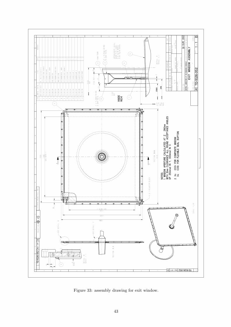
Figure 33: assembly drawing for exit window.
43