LHB Handbook on Maintof Air Brake System in LHB Coaches (FTIL Type)(1)
120
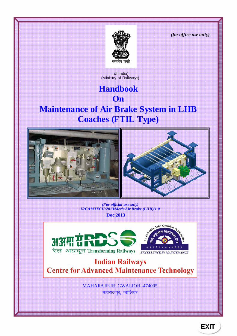
(for office use only) . of India) (Ministry of Railways) Handbook On Maintenance of Air Brake System in LHB Coaches (FTIL Type) (For official use only) IRCAMTECH/2013/Mech/Air Brake (LHB)/1.0 Dec 2013 MAHARAJPUR, GWALIOR -474005 egkjktiq j, Xokfy;j
-
Upload
rakesh-jainwal -
Category
Documents
-
view
386 -
download
40
description
LHB Handbook on Maintof Air Brake System in LHB Coaches (FTIL Type)(1)
Transcript of LHB Handbook on Maintof Air Brake System in LHB Coaches (FTIL Type)(1)
(for office use only)
. of India) (Ministry of Railways)
Handbook On
Maintenance of Air Brake System in LHB Coaches (FTIL Type)
(For official use only) IRCAMTECH/2013/Mech/Air Brake (LHB)/1.0
Dec 2013
MAHARAJPUR, GWALIOR -474005
egkjktiqj, Xokfy;j
Foreword
This Maintenance hand book has covered introduction,
constructional detail of Air Brake System (FTIL type), instructions
and precautions during inspection and maintenance. Wherever
required, sketches and colored photographs have been provided to
make the understanding clear.
I am sure that this maintenance handbook will be useful to the
concerned staff to ensure trouble free service of the train operation.
Technological up-gradation and learning is a continuous process.
Hence feel free to write us for any addition / modifications or in
case you have any suggestion to improve the Hand Book, your
contribution in this direction shall be highly appreciated.
We welcome any suggestion for addition and improvements from our readers.
Place: CAMTECH/GWL (A R Tupe ) Date: 22/12/2013 Exe. Director
CAMTECH/GWL
PREFACE
Air Brake System (FTIL type) has been introduced for LHB type coaches. LHB coaching stocks with Brake system (FTIL type) on Indian Railway are working with twin pipe graduated release air brake system. Air brake system of LHB coaches is most efficient and reliable braking system used to run long trains at high speeds. The maintenance & Component details of Air Brake System (FTIL type) for coaching stocks are given in this handbook.
The purpose of this maintenance hand book is to enhance knowledge and competence of C&W staff in dealing with Air Brake System in coaching stock maintenance.
This hand book is aimed at assisting concerned staff and does not supersede any existing instructions from Railway Board, RDSO or IRCA etc. Most of data and informations mentioned here in are available in some form the other in various books and manuals or other printed matters. If any changes are made, these will be used in the form of correction slips. For convenience, this book includes a proforma for entering all correction slips serially.
Technological upgradation and learning is a continuous process. Hence feel free to write us any addition / modification in this handbook or in case you have any suggestion to improve the handbook. Your contribution in this direction will be appreciated.
We welcome any suggestion for addition and improvements from our readers.
Date: - 26.12.2012
K.P. Yadav Director/ Mech
CAMTECH/GWL
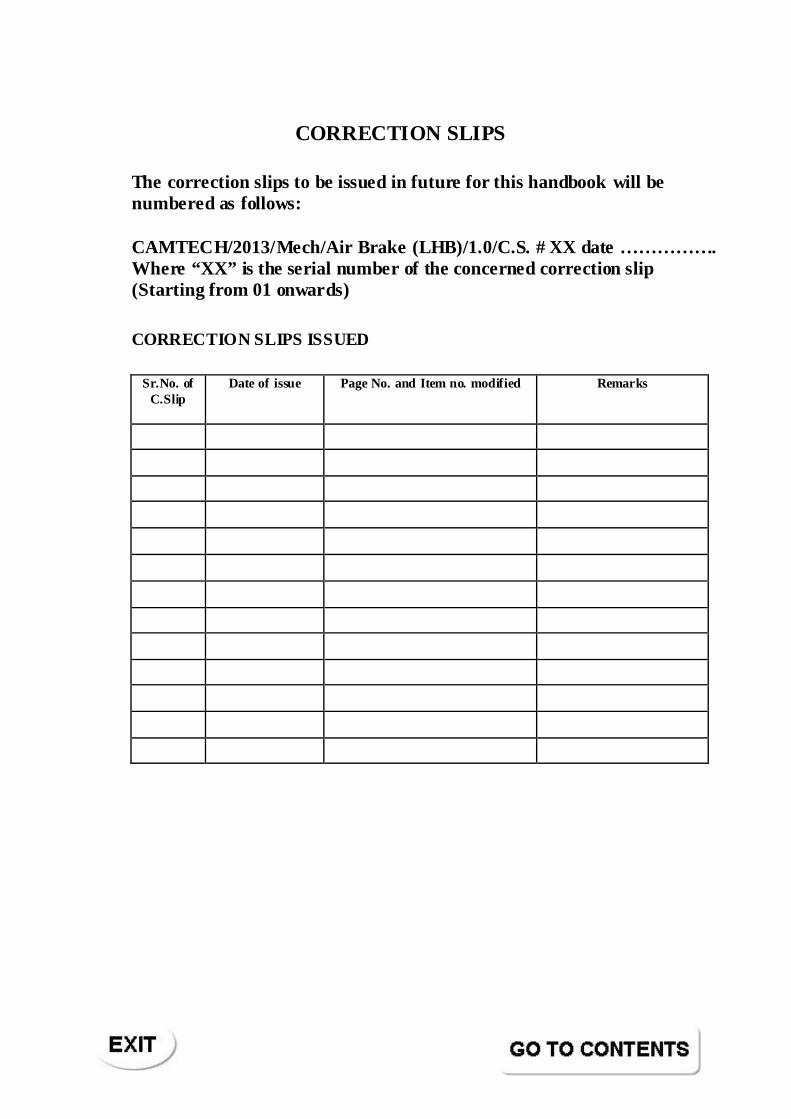
CORRECTION SLIPS
The correction slips to be issued in future for this handbook will be numbered as follows:
CAMTECH/2013/Mech/Air Brake (LHB)/1.0/C.S. # XX date ……………. Where “XX” is the serial number of the concerned correction slip (Starting from 01 onwards)
CORRECTION SLIPS ISSUED
Sr.No. of C.Slip
Date of issue Page No. and Item no. modified Remarks
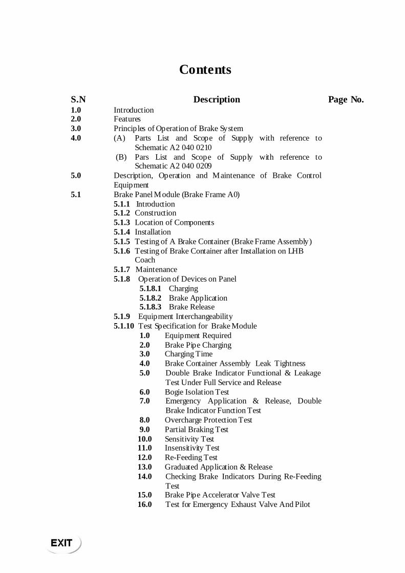
Contents
S.N Description Page No. 1.0 Introduction 2.0 Features 3.0 Principles of Operation of Brake System 4.0 (A) Parts List and Scope of Supply with reference to
Schematic A2 040 0210
(B) Pars List and Scope of Supply with reference to Schematic A2 040 0209
5.0 Description, Operation and Maintenance of Brake Control Equipment
5.1 Brake Panel Module (Brake Frame A0) 5.1.1 Introduction 5.1.2 Construction 5.1.3 Location of Components 5.1.4 Installation 5.1.5 Testing of A Brake Container (Brake Frame Assembly) 5.1.6 Testing of Brake Container after Installation on LHB
Coach
5.1.7 Maintenance 5.1.8 Operation of Devices on Panel 5.1.8.1 Charging 5.1.8.2 Brake Application 5.1.8.3 Brake Release 5.1.9 Equipment Interchangeability 5.1.10 Test Specification for Brake Module 1.0 Equipment Required 2.0 Brake Pipe Charging 3.0 Charging Time 4.0 Brake Container Assembly Leak Tightness 5.0 Double Brake Indicator Functional & Leakage
Test Under Full Service and Release
6.0 Bogie Isolation Test 7.0 Emergency Application & Release, Double
Brake Indicator Function Test
8.0 Overcharge Protection Test 9.0 Partial Braking Test 10.0 Sensitivity Test 11.0 Insensitivity Test 12.0 Re-Feeding Test 13.0 Graduated Application & Release 14.0 Checking Brake Indicators During Re-Feeding
Test
15.0 Brake Pipe Accelerator Valve Test 16.0 Test for Emergency Exhaust Valve And Pilot
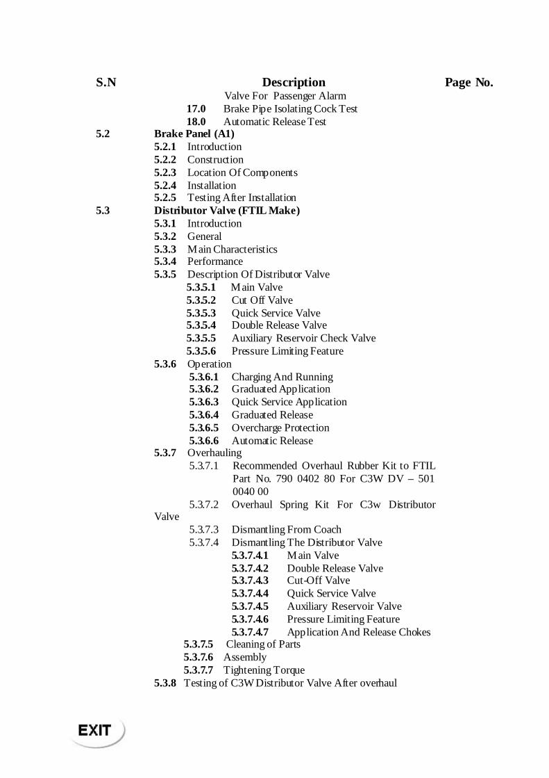
S.N Description Page No. Valve For Passenger Alarm
17.0 Brake Pipe Isolating Cock Test 18.0 Automatic Release Test 5.2 Brake Panel (A1) 5.2.1 Introduction 5.2.2 Construction 5.2.3 Location Of Components 5.2.4 Installation 5.2.5 Testing After Installation 5.3 Distributor Valve (FTIL Make) 5.3.1 Introduction 5.3.2 General 5.3.3 Main Characteristics 5.3.4 Performance 5.3.5 Description Of Distributor Valve 5.3.5.1 Main Valve 5.3.5.2 Cut Off Valve 5.3.5.3 Quick Service Valve 5.3.5.4 Double Release Valve 5.3.5.5 Auxiliary Reservoir Check Valve 5.3.5.6 Pressure Limiting Feature 5.3.6 Operation 5.3.6.1 Charging And Running 5.3.6.2 Graduated Application 5.3.6.3 Quick Service Application 5.3.6.4 Graduated Release 5.3.6.5 Overcharge Protection 5.3.6.6 Automatic Release 5.3.7 Overhauling 5.3.7.1 Recommended Overhaul Rubber Kit to FTIL
Part No. 790 0402 80 For C3W DV – 501 0040 00
5.3.7.2 Overhaul Spring Kit For C3w Distributor Valve
5.3.7.3 Dismantling From Coach 5.3.7.4 Dismantling The Distributor Valve 5.3.7.4.1 Main Valve 5.3.7.4.2 Double Release Valve 5.3.7.4.3 Cut-Off Valve 5.3.7.4.4 Quick Service Valve 5.3.7.4.5 Auxiliary Reservoir Valve 5.3.7.4.6 Pressure Limiting Feature 5.3.7.4.7 Application And Release Chokes 5.3.7.5 Cleaning of Parts 5.3.7.6 Assembly 5.3.7.7 Tightening Torque 5.3.8 Testing of C3W Distributor Valve After overhaul
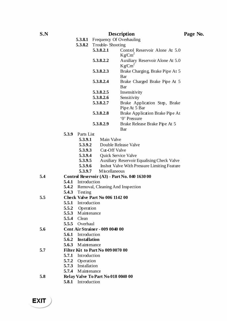
S.N Description Page No. 5.3.8.1 Frequency Of Overhauling 5.3.8.2 Trouble- Shooting 5.3.8.2.1 Control Reservoir Alone At 5.0
Kg/Cm2
5.3.8.2.2 Auxiliary Reservoir Alone At 5.0 Kg/Cm2
5.3.8.2.3 Brake Charging, Brake Pipe At 5 Bar
5.3.8.2.4 Brake Charged Brake Pipe At 5 Bar
5.3.8.2.5 Insensitivity 5.3.8.2.6 Sensitivity 5.3.8.2.7 Brake Application Step, Brake
Pipe At 5 Bar
5.3.8.2.8 Brake Application Brake Pipe At ‘0’ Pressure
5.3.8.2.9 Brake Release Brake Pipe At 5 Bar
5.3.9 Parts List 5.3.9.1 Main Valve 5.3.9.2 Double Release Valve 5.3.9.3 Cut-Off Valve 5.3.9.4 Quick Service Valve 5.3.9.5 Auxiliary Reservoir Equalising Check Valve 5.3.9.6 Inshot Valve With Pressure Limiting Feature 5.3.9.7 Miscellaneous 5.4 Control Reservoir (A3) - Part No. 040 1630 00 5.4.1 Introduction 5.4.2 Removal, Cleaning And Inspection 5.4.3 Testing 5.5 Check Valve Part No 006 1142 00 5.5.1 Introduction 5.5.2 Operation 5.5.3 Maintenance 5.5.4 Clean 5.5.5 Overhaul 5.6 Cent Air Strainer - 009 0040 00 5.6.1 Introduction 5.6.2 Installation 5.6.3 Maintenance 5.7 Filter Kit to Part No 009 0070 00 5.7.1 Introduction 5.7.2 Operation 5.7.3 Installation 5.7.4 Maintenance 5.8 Relay Valve To Part No 018 0040 00 5.8.1 Introduction
S.N Description Page No. 5.8.2 Operation 5.8.2.1 Brake Application 5.8.2.2 Brake Release 5.8.3 Maintenance 5.8.4 Overhaul 5.8 5 Re-Assembly 5.8.6 Test Procedure
5.8.7 Reassembly On Brake Panel
5.8.8 Procedure For Testing 5.8.9 Parts List 5.9 Pressure Switch To Part No 040 1090 00 5.10 Health And Safety 5.11 General Hints on Maintenance of Air Brake System 5.12 General Tools for Attention to Air Brake Equipment and
Facilities
5.12.1 Additional General Tools for Periodic Overhaul at Workshops
5.13 Test Rigs for IOH & POH Repairs 5.14 Cleaning Procedure (Air Brake Equipments /Components) 5.15 Inspection/Replacement Criteria (Air Brake Equipment/
Components)
5.16 Lubrication And Recommended Greases
5.17 Special Instructions For Storage Of Rubber Components 6.0 Recommended Schedule Maintenance Attention for LHB
Coach Equipment
7.0 About The Brake Panel
Handbook On
Maintenance of Air Brake System in LHB Coaches
(FTIL Type)
No.IRCAMTECH/M/13-14/Air Brake Sy stem (FTIL ty pe)/1.0
Maintenance Handbook o f Air Brake System (FTIL type) 1
LHB COACH BRAKE SYSYEM (FTIL Type)
1.0 INTRODUCTION
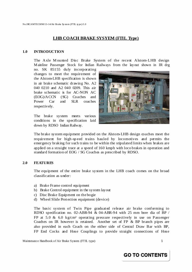
The Axle M ounted Disc Brake System of the recent Alstom-LHB design M ainline Passenger Stock for Indian Railways from the layout shown in IR drg no. SK 85155 duly incorporating changes to meet the requirement of the Alstom-LHB specification is shown in air brake schematic drawing No. A2 040 0210 and A2 040 0209. This air brake schematic is for AC-NON AC (EOG)/ACCN (SG) Coaches and Power Car and SLR coaches respectively. The brake system meets various conditions in the specification laid down by RDSO Indian Railway.
The brake system equipment provided on the Alstom-LHB design coaches meet the requirement for high-sp eed trains hauled by locomotives and permits the emergency braking for such trains to be within the stipulated limits when brakes are applied on a straight trace at a speed of 160 kmph with loco brakes in operation and standard formation of EOG / SG Coaches as prescribed by RDSO.
2.0 FEATURES
The equipment of the entire brake system in the LHB coach comes on the broad classification as under: a) Brake Frame control equipment b) Brake Control equipment in the system layout c) Disc Brake Equipment on the bogie d) Wheel Slide Protection equipment (device)
The basic system of Twin Pipe graduated release air brake conforming to RDSO specification no. 02-ABR-94 & 04-ABR-94 with 25 mm bore dia of BP / FP at 5.0 & 6.0 kg/cm² operat ing pressure respectively in use on Passenger Coaches on IR however is retained. Another set of FP & BP branch pipes are also provided in each Coach on the either side of Central Draw Bar with BP, FP End Cocks and Hose Couplings to provide straight connections of Hose
No.IRCAMTECH/M/13-14/Air Brake Sy stem (FTIL ty pe)/1.0
Maintenance Handbook o f Air Brake System (FTIL type) 2
Coupling sets during the reversal and attachment of the Coaches to the formation.
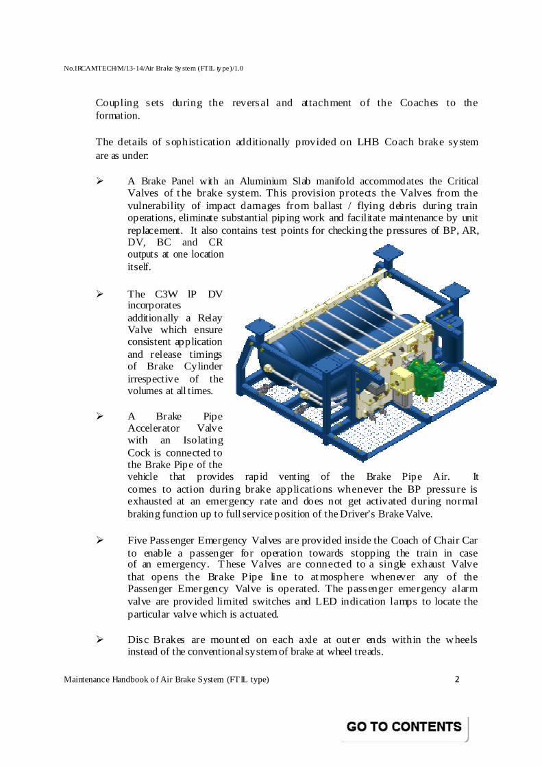
The details of sophistication additionally provided on LHB Coach brake system are as under: � A Brake Panel with an Aluminium Slab manifo ld accommodates the Critical
Valves of t he brake system. This provision protects the Valves from the vulnerability of impact damages from ballast / flying debris during train operations, eliminate substantial piping work and facilitate maintenance by unit replacement. It also contains test points for checking the pressures of BP, AR, DV, BC and CR outputs at one location itself.
� The C3W lP DV incorporates additionally a Relay Valve which ensure consistent application and release timings of Brake Cylinder irrespective of the volumes at all times.
� A Brake Pipe
Accelerator Valve with an Isolating Cock is connected to the Brake Pipe of the vehicle that provides rapid venting of the Brake Pipe Air. It comes to action during brake applications whenever the BP pressure is exhausted at an emergency rate and does not get activated during normal braking function up to full service position of the Driver’s Brake Valve.
� Five Passenger Emergency Valves are provided inside the Coach of Chair Car
to enable a passenger for operation towards stopping the train in case of an emergency. These Valves are connected to a single exhaust Valve that opens the Brake Pipe line to atmosphere whenever any of the Passenger Emergency Valve is operated. The passenger emergency alarm valve are provided limited switches and LED indication lamps to locate the particular valve which is actuated.
� Disc Brakes are mounted on each axle at outer ends within the wheels
instead of the conventional system of brake at wheel treads.
No.IRCAMTECH/M/13-14/Air Brake Sy stem (FTIL ty pe)/1.0
Maintenance Handbook o f Air Brake System (FTIL type) 3
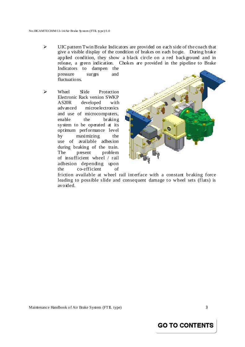
� UIC pattern Twin Brake Indicators are provided on each side of the coach that give a visible display of the condition of brakes on each bogie. During brake applied condition, they show a black circle on a red background and in release, a green indication. Chokes are provided in the pipeline to Brake Indicators to dampen the pressure surges and fluctuations.
� Wheel Slide Protection
Electronic Rack version SWKP AS20R developed with advanced microelectronics and use of microcomputers, enable the braking system to be operated at its optimum performance level by maximizing the use of available adhesion during braking of the train. The present problem of insufficient wheel / rail adhesion depending upon the co-efficient of friction available at wheel rail interface with a constant braking force leading to possible s lide and consequent damage to wheel sets (flats) is avoided.
No.IRCAMTECH/M/13-14/Air Brake Sy stem (FTIL ty pe)/1.0
Maintenance Handbook o f Air Brake System (FTIL type) 4
3.0 PRINCIPLES OF OPERATION OF BRAKE SYSTEM
When the Twin Pipe System with BP and FP lines on the coaches of the train is charged to 5.0 & 6.0 kg/cm² respectively by the locomotive, the air pressure in the air Brake Pipe connected to the Distributor Valves (A2), controls the brake system of the coaches. To initiate and effect a brake application, the air pressure in the Brake Pipe is reduced and the Distributor Valve in each coach reacts to supply the Auxiliary Reservoir air pressure at a proportionate level as BC pressure to the Actuators. This BC pressure acts as a s ignal pressure to the large capacity Relay Valve (A17). The Relay Valve in turn quickly supplies air pressure of the same intensity to the four Wheel Slide Dump Valves (D2) and finally reaches the two Brake Actuators provided one for each Brake Disc. The force developed in each Brake Cylinder causes Piston movement and subsequently through linkage passes on to its Brake Caliper with Pads (C2) to close on the individual Brake Disc provided in each wheel set. The binding causes friction and retardation to wheel rotation. The force applied on the Disc and the brake effect will be proportional to the BC pressure supplied to the Brake Cylinder. The detailed description and maintenance of Disc Brake mechanical arrangement consisting of Calip er with Pads, Brake Cylinder, etc., is dealt with in a separate manual (Refer no. E 9060)
If wheel s lip occurs on any wheel consequent to the brake force from the Disc not having been absorbed due to insufficient wheel / rail adhesion factors, a Sensor (D1) provided in axle end cover and Phonic Wheel (D6) fitted on one axle end of each wheel in combination feeds the signal to the Wheel Slide Protection Unit (D3). The WSP Unit in turn energizes through Dump Valve cabling / Connector (D10) instantly and operates the particular wheel slide Dump Valve (Solenoid Valve) provided in the Brake Cylinder circuit of the particular wheel. The Dump Valve gets opened and exhaust the BC pressure to atmosphere to maximize the braking effort for any given wheel / rail interface coefficient of friction.
As soon as the wheel slide is stopped, the Sensor withdraws the electrical signal to WSP Unit and the later in turn automatically deactivates the Dump Valve to a close position. This allows restoration of BC pressure to the Brake Cylinder circuit due to the pressure-maintaining feature of DV. The Wheel Slide Protection is thus automatic in action and makes optimum use of adhesion during braking with resultant benefits of improved braking distance and prevent ion of continuous wheel s lide / damages. The detailed description and maintenance of WSP unit is covered in a separate manual (Refer no. SWKP AS20 R).
No.IRCAMTECH/M/13-14/Air Brake Sy stem (FTIL ty pe)/1.0
Maintenance Handbook o f Air Brake System (FTIL type) 5
Reduction in the Brake Pip e air pressure can be caused by any one of the operations / events as under: a) Driver’s Automatic Brake Valve on the Locomotive b) Guard’s Brake Control in Brake Van c) Pilot Valve for Passenger Emergency d) Parting of train and disengagement of Brake Pipe Of t hese, in resp ect of Driver’s Automatic Valve operation only, it can provide a graduated brake application or release. For any Brake Pip e pressure held steadily below the normal running regime pressure of 5.0 kg/cm², a brake application by way of Brake Cylinder pressure build up will be caused by the DV and will be held steadily at the prop ortionate level against normal leakage in the system.
Release of brake is affected by the movement of Driver’s Automatic Brake Valve handle towards release position causing the BP pressure to increase towards regime pressure limit. The DV in turn causes the BC pressure to be withdrawn proportionately depending upon the increase of BP pressure. A reduced brake app lication or a complete release of brake can be provided depending upon the position of Brake Valve Handle selected.
No.IRCAMTECH/M/13-14/Air Brake Sy stem (FTIL ty pe)/1.0
Maintenance Handbook o f Air Brake System (FTIL type) 6
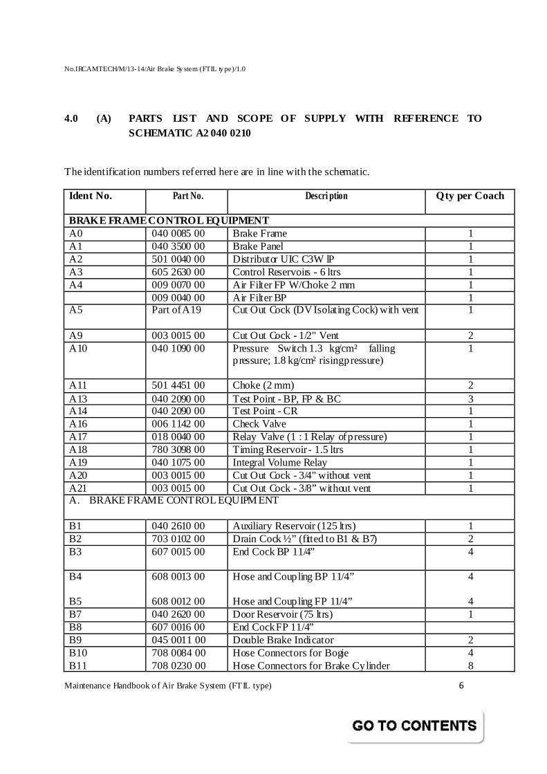
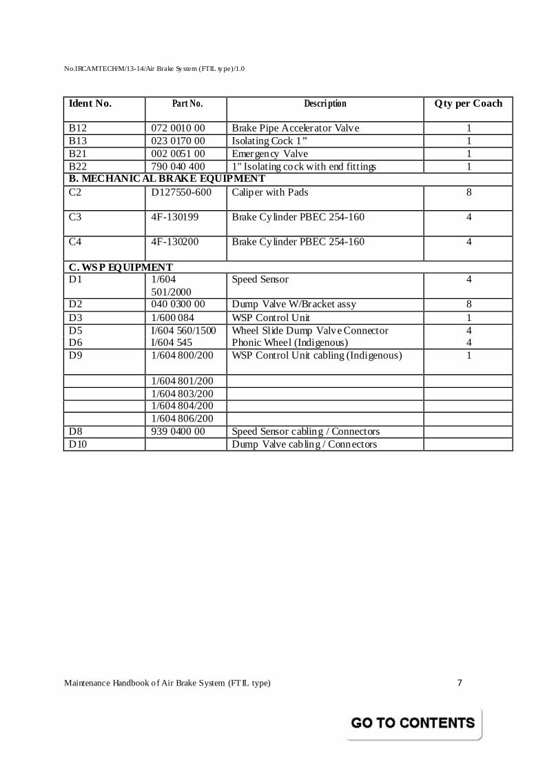
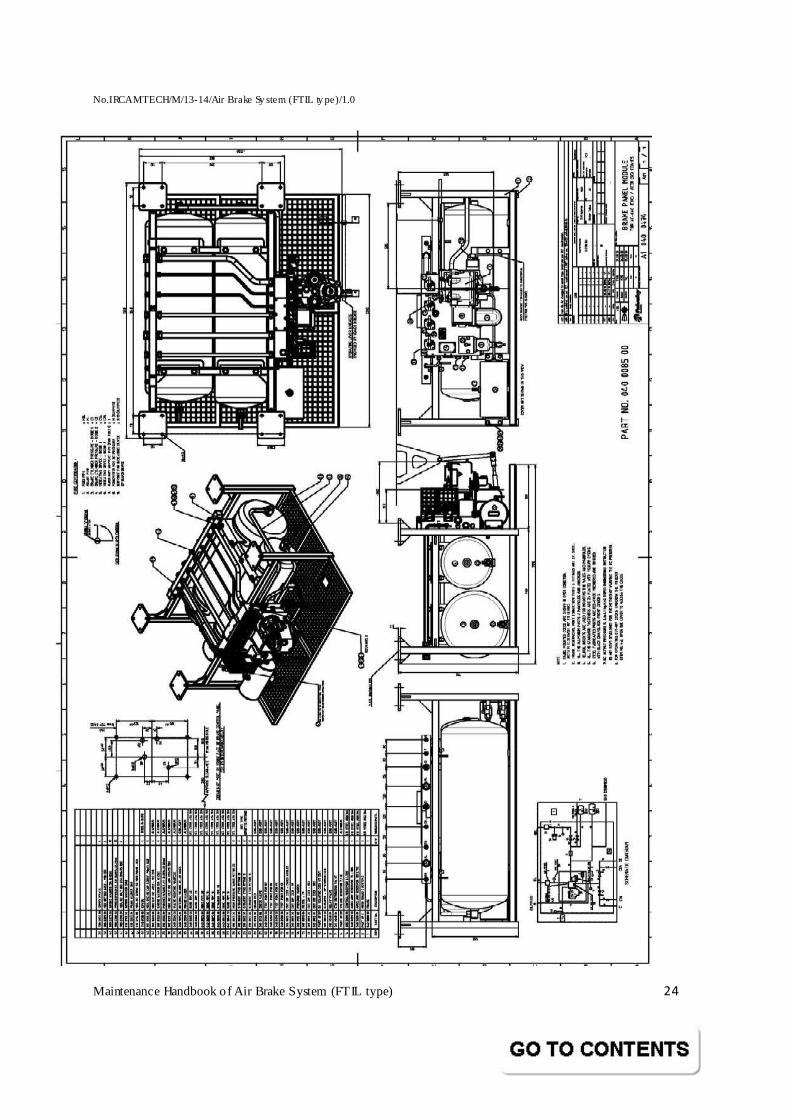
4.0 (A) PARTS LIST AND SCOPE OF SUPPLY WITH REFERENCE TO SCHEMATIC A2 040 0210 The identification numbers referred here are in line with the schematic. Ident No. Part No. Descri ption Qty per Coach
BRAKE FRAME CONTROL EQUIPMENT A0 040 0085 00 Brake Frame 1 A1 040 3500 00 Brake Panel 1 A2 501 0040 00 Distributor UIC C3W lP 1 A3 605 2630 00 Control Reservoirs - 6 ltrs 1 A4 009 0070 00 Air Filter FP W/Choke 2 mm 1 009 0040 00 Air Filter BP 1 A5 Part of A19 Cut Out Cock (DV Isolating Cock) with vent
1
A9 003 0015 00 Cut Out Cock - 1/2" Vent 2 A10 040 1090 00 Pressure Switch 1.3 kg/cm² falling
pressure; 1.8 kg/cm² rising pressure)
1
A11 501 4451 00 Choke (2 mm) 2 A13 040 2090 00 Test Point - BP, FP & BC 3 A14 040 2090 00 Test Point - CR 1 A16 006 1142 00 Check Valve 1 A17 018 0040 00 Relay Valve (1 : 1 Relay of pressure) 1 A18 780 3098 00 Timing Reservoir - 1.5 ltrs 1 A19 040 1075 00 Integral Volume Relay 1 A20 003 0015 00 Cut Out Cock - 3/4" without vent 1 A21 003 0015 00 Cut Out Cock - 3/8” without vent 1 A. BRAKE FRAME CONTROL EQUIPM ENT B1 040 2610 00 Auxiliary Reservoir (125 ltrs) 1 B2 703 0102 00 Drain Cock ½” (fitted to B1 & B7) 2 B3 607 0015 00
End Cock BP 11/4” 4
B4 608 0013 00
Hose and Coupling BP 11/4” 4
B5 608 0012 00 Hose and Coupling FP 11/4” 4 B7 040 2620 00 Door Reservoir (75 ltrs) 1 B8 607 0016 00 End Cock FP 11/4” B9 045 0011 00 Double Brake Indicator 2 B10 708 0084 00 Hose Connectors for Bogie 4 B11 708 0230 00 Hose Connectors for Brake Cylinder 8
No.IRCAMTECH/M/13-14/Air Brake Sy stem (FTIL ty pe)/1.0
Maintenance Handbook o f Air Brake System (FTIL type) 7
Ident No. Part No. Descri ption Qty per Coach
B12 072 0010 00 Brake Pipe Accelerator Valve 1 B13 023 0170 00 Isolating Cock 1” 1 B21 002 0051 00 Emergency Valve 1 B22 790 040 400 1" Isolating cock with end fittings 1 B. MECHANICAL BRAKE EQUIPMENT C2 D127550-600 Caliper with Pads
8
C3 4F-130199 Brake Cylinder PBEC 254-160
4
C4 4F-130200 Brake Cylinder PBEC 254-160
4
C. WSP EQUIPMENT D1 1/604
501/2000 Speed Sensor 4
D2 040 0300 00 Dump Valve W/Bracket assy 8 D3 1/600 084 WSP Control Unit 1 D5 I/604 560/1500 Wheel Slide Dump Valve Connector 4 D6 I/604 545 Phonic Wheel (Indigenous) 4 D9 1/604 800/200
WSP Control Unit cabling (Indigenous) 1
1/604 801/200 1/604 803/200 1/604 804/200 1/604 806/200 D8 939 0400 00 Speed Sensor cabling / Connectors D10 Dump Valve cabling / Connectors

No.IRCAMTECH/M/13-14/Air Brake Sy stem (FTIL ty pe)/1.0
Maintenance Handbook o f Air Brake System (FTIL type) 8
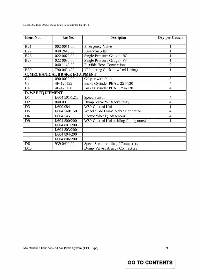
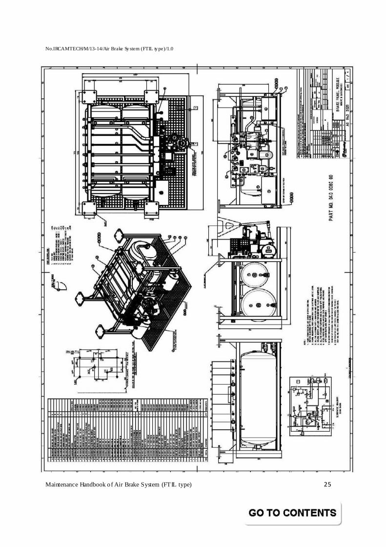
(B) PARTS LIST AND SCOPE OF SUPPLY WITH REFERENCE TO SCHEMATIC A2 040 0209
Ident No. Part No. Descri ption Qty per Coach
A. BRAKE FRAME CONTROL EQUIPMENT A0 040 0080 00 Brake Frame 1 A1 040 3500 00 Brake Panel 1 A2 501 0040 00 Distributor UIC C3W lP 1 A3 605 2630 00 Control Reservoirs – 6 ltrs 1 A4 009 0070 00 Air Filter FP W/Choke 2 mm 1 009 0040 00 Air Filter BP 1 A5 Part of A19 Cut Out Cock (DV Isolating Cock) with
vent 1
A9 003 0015 00 Cut Out Cock – 1/2" Vent 2 A10 040 1090 00 Pressure Switch (1.3 kg/cm² falling
pressure; 1.8 kg/cm² rising pressure) 1
A11 501 4451 00 Choke (2 mm) 2 A13 040 2090 00 Test Point – BP, FP & BC 3 A14 040 2090 00 Test Point - CR 1 A16 006 1142 00 Check Valve 2 A17 018 0040 00 Relay Valve (1 : 1 Relay of pressure) 1 A18 780 3098 00 Timing Reservoir – 1.5 ltrs 1 A19 040 1075 00 Integral Volume Relay 1 A20 003 0015 00 Cut Out Cock – 3/4" without vent 1 A21 003 0015 00 Cut Out Cock – 3/8” without vent 1 B. BRAKE FRAME CONTROL EQUIPMENT B1 040 2610 00 Auxiliary Reservoir (125 ltrs) 1 B2 703 0102 00 Drain Cock ½” (fitted to B1 & B7) 2 B3 607 0015 00 End Cock BP 1-1/4” 4 B4 608 0013 00 Hose and Coupling BP 1-1/4” 4 B5 608 0012 00 Hose and Coupling FP 1-1/4” 4 B7 040 2620 00 Door Reservoir(75 ltrs) 1 B8 607 0016 00 End Cock FP 1-1/4” 4 B9 045 0011 00 Double Brake Indicator 2 B10 708 0084 00 Hose Connectors for Bogie 4 B11 708 0230 00 Hose Connectors for Brake Cylinder 8 B12 072 0010 00 Brake Pipe Accelerator Valve 1 B13 023 0170 00 Isolating Cock 1” 1 B14 022 0080 00 Single Pressure Gauge - BP 1 B17 040 0050 00 Roller Operated Valve (3 way) 1 B17 790 040 330 Gaurds Emergency Cock 3/4" 1 B18 045 0020 00 Single Brake Indicator 1
No.IRCAMTECH/M/13-14/Air Brake Sy stem (FTIL ty pe)/1.0
Maintenance Handbook o f Air Brake System (FTIL type) 9
Ident No. Part No. Descri ption Qty per Coach
B21 002 0051 00 Emergency Valve 1 B22 040 2640 00 Reservoir 5 lts 1 B23 022 0070 00 Single Pressure Gauge - BC 1 B28 022 0090 00 Single Pressure Gauge - FP 1 - 040 1140 00 Flexible Hose Connection 2 B30 790 040 400 1" Isolating Cock 1" w/end f ittings 1 C. MECHANICAL BRAKE EQUIPMENT C2 090 0020 00 Caliper with Pads 8 C3 4F-125155 Brake Cylinder PBAC 254-130 4 C4 4F-125156 Brake Cylinder PBAC 254-130 4 D. WSP EQUIPMENT D1 I/604 501/1210 Speed Sensor 4 D2 040 0300 00 Dump Valve W/Bracket assy 4 D3 I/600 084 WSP Control Unit 1 D5 I/604 560/1500 Wheel Slide Dump Valve Connector 4 D6 I/604 545 Phonic Wheel (Indigenous) 4 D9 I/604 800/200 WSP Control Unit cabling (Indigenous) 1 I/604 801/200 I/604 803/200 I/604 804/200 I/604 806/200 D8 Speed Sensor cabling / Connectors D10
939 0400 00 Dump Valve cabling / Connectors
No.IRCAMTECH/M/13-14/Air Brake Sy stem (FTIL ty pe)/1.0
Maintenance Handbook o f Air Brake System (FTIL type) 10
5.0 DESCRIPTION, OPERATION AND MAINTENANCE OF BRAKE CONTROL EQUIPMENT
5.1 BRAKE PANEL MODULE (Brake Frame A0)
5.1.1 INTRODUCTION
The Brake Panel Module for LHB Coach serves to group together with interconnect ions in one s ingle assembly all Valves, Cut Out Cock, Drain Cock, Pressure Switch housed in a Braking Panel with Reservoirs, Choke Filters, etc., of the brake equip ment within the space marked as A0 of t he brake schematic. Other equip ment in the schematic are allocated in sp ecial p laces of the Coach braking layout. It facilitates easy removal for overhaul and unit replacement.
5.1.2 CONSTRUCTION
The Brake Panel Module is a fabricated stainless steel frame and contains a Aluminium Manifold to which component / subassemblies are attached. The list of items forming part of their location is included in the parts list of Brake Container drawing along with the piping circuit details.
5. 1.3 LOCA TION OF C OMP ON ENTS
The brake equip ment components are positioned in compact groups at convenient locations and pneumatic interconnect ions are formed by passages within the valve mounting manifold as well as by external p ip ing circuits. The port identif ication for the input/output air connect ions from the overall brake schematic of the Coach is indicated in the schematics.
The Brake Container also includes a Check Valve and four test points for measuring the BP, FP, BC & AR pressures during testing.
Frame Header mounted on rear top position of the Brake Container form an interface connection with Coaching braking system for BP, FP, BC, etc., as indicated in the port connection details in the schematics. Centrifugal air strainer is provided in the brake pipe entry port in the manifold with a drain cock attachment to trap and drain the condensate periodicaly with ease. The feed pipe is provided with an air strainer only. Since the pressure fluctuation in the feed pipe are very low to cause condensates collection.
All the mounted components on the Brake Container have identifying labels. For certain items identification letters are punched directly on or near the item itself.
The four Cut Out Cocks have open/close labels indicating the handle position.
No.IRCAMTECH/M/13-14/Air Brake Sy stem (FTIL ty pe)/1.0
Maintenance Handbook o f Air Brake System (FTIL type) 11
5.1.4 INSTALLATION
The Brake Panel Module frame comprising the pre-assembled pneumatic system with individually tested components installed in position can conveniently be mounted to the LHB Coach under frame mounting bracket (not in our scope of supply). The four mounting flanges on top of the Brake Container carry four 12 mm holes each. The Brake Container flanges are to be secured with fasteners to Coach under frame bracket with Stainless steel washer interfaced in between them.
The mounting has to be done with the DV face on the Brake Panel facing outward to facilit ate attention to equipment. Suitable anti-slackening scheme is to be adopted for the Nuts to prevent them working out in service due to likely vibration in operating conditions.
5.1.5 TESTING OF A BRAKE CONTAINER (BRAKE FRAME ASS EMBLY)
The Brake Panel Module frame comprising the pre-assembled pneumatic system with individual tested equipment is to be tested aft er overhaul for its performance as per the FTIL test procedure indicated in Annexure - A attached along with the Test Rig Schematic.
5.1.6 TESTING OF BRAKE CONTAINER AFTER INSTALLATION ON LHB COACH
It is suggested that t he Brake Control Rack comp lete be t ested in the workshop before being commissioned in the coach. Even after commissioning, the system performance has to be retested using a Single Car Mobile Test Rig.
5.1.7 MAINTENANCE
The Brake Panel Module practically does not require any maintenance except for a check on the fastening arrangement to the Coach frame for ensuring soundness and air leak tightness of the system. However, for the brake equipment part, the periodic recommended maintenance schedule between overhauls is indicated in a chart under general chapter covered in Part A. The periodic overhaul and test procedure for the individual equipment forming part of the Brake Container is covered under this section separately.
No.IRCAMTECH/M/13-14/Air Brake Sy stem (FTIL ty pe)/1.0
Maintenance Handbook o f Air Brake System (FTIL type) 12
5.1.8 OPERATION OF DEVICES ON PANEL: 5.1.8.1 CHARGING:
Initially the Brake Pipe pressure enters the Brake Panel through port (HL) and passes through a Centrifugal Air Strainer with Drain Cock (A4). If the DV Isolating Cock (A5) mounted on the Valve Mounting Manifold assembly is opened, the BP pressure enters the C3W Distributor Valve (A2) via a BP test point (A13) and charges the Control Reservoir 6 litres (A3) via a CR test point (A14) and the Auxiliary Reservoir - 125 litres (B1). Externally the BP pressure charges into the BP Accelerator Valve (B12) through an Isolating Cock (B13). The BP pressure also enters the Emergency Exhaust Valve (B21) inlet port and charges the Passenger Emergency Alarm Pilot Valves (B6).
The Feed Pip e pressure enters t he Brake p anel through port (HBL) and passes through a Air Strainer (A4). Further, f iltered air passes from the Strainer passes through a Pressure Switch assy (A10) and a FP test point (A13). If the Isolating Cock (A20) is opened, the air will charge into the Auxiliary Reservoir-125 litres (B7) to maintain continuous supply of compressed for braking purposes.
The air opens the Check Valve (A16) and charges the Auxiliary Reservoir-125 litres to the Feed Pipe pressure. If the Isolating Cock (A21) is opened, the air will leave the panel through port T of the Header which can be used for auxiliary equipment such as for door operation and flushing of toilets etc. The Feed Pipe pressure also enters the MR port of Relay Valve (A17) and Distributor valve (A2) and acts as a Main Reservoir supply to these devices.
5.1.8.2 BRAKE AP PLIC ATION:
When a Brake is applied, BP pressure is reduced in the system through the Driver’s Brake Valve and BC pressure charges from the Distributor Valve (A2) into a Timing Volume Reservoir (A16) through a Choke and enters the signal port of the Relay Valve (A17) which in turn delivers the same pressure (1:1 pressure ratio). The output pressure from the Relay Valve (A17) leads to the Bogie Isolating Cocks BC1 and BC2 (Schematic ref. nos. A9 & A10 respectively). When the Cocks are opened the air leaves the p anel through ports C1 and C2 and goes to t he Actuators (B11) through the Dump Valves (D2) causing a brake application. The BC air also leaves the Panel through ports C1A and C2A and goes to the Double Brake Indicators (B9) through a dia 2 mm Choke. In this condition, window of the Brake Indicator shows a Red colour with a black stripe. When an emergency brake is applied, the BP Accelerator Valve (B12) vents the BP pressure through its exhaust port rapidly causing quicker brake application through the train. Whenever the Passenger Emergency Alarm Pilot Valve handle is pulled, the BP pressure vents at its exhaust port and causes the Emergency Exhaust Valve (B6) to open and thereby vent the BP pressure continuously to cause a brake application. Using the resetting key, the Passenger Emergency Pilot Valve can be reset to stop venting of BP air through the Emergency Exhaust Valve.
No.IRCAMTECH/M/13-14/Air Brake Sy stem (FTIL ty pe)/1.0
Maintenance Handbook o f Air Brake System (FTIL type) 13
5.1.8.3 BRAKE RELEASE:
When the Brake is released, BP pressure is again charged into the system thereby releasing the brakes. Venting the control BC pressure takes place through the DV and the actual BC pressure at the Relay Valve Exhaust port. Aft er release, the windows of the Brake Indicators turn to Green colour signaling a brake release.
5.1.9 EQUIPMENT INTERCHANGEABILITY:
Unit-wise inter-changeability is provided for the following equipment with M/s Knorr
Supplies: 1. Brake Control rack assy (A0)
2. Distributor Valve (A2), together with its Integral Sandwich Piece, Relay,
Timing Volume & Intermediate plate
3. Brake Pipe Accelerator Valve with Pipe Bracket (B12)
4. Double Brake Indicators (B9) *
5. Passenger Emergency Alarm Pilot Valve (B6) *
6. Emergency Exhaust Valve (B21)
7. Isolating Cock (B13)
8. WSP Dump Valves with mounting brackets & Sealing Rings (D2)
9. BP & FP Hoses (B4 & B5)
10. Angle Cocks (B3 & B8)
11. Actuator Hoses (B11)
* Two sets of holes are drilled in the mounting location of these two devices to provide unit-wise inter-changeability.
No.IRCAMTECH/M/13-14/Air Brake Sy stem (FTIL ty pe)/1.0
Maintenance Handbook o f Air Brake System (FTIL type) 14
5.1.10 TEST SPECIFICATION FOR BRAKE MODULE
TO PART NO. 040 0080 00 & 040 0085 00
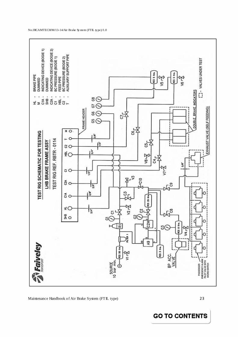
1.0 EQUIPMENT REQUIRED:
• Pneumatic test stand - RBTR • Bulb Indication unit to be connected to a Micro Switch for the purpose of verifying the operation of the flasher lights provided in the coach. • Precision Pressure Gauge (0-10 kg/cm²) for connection at CR test point with flexible connection. • Precision Pressure Gauge for connection at Reservoir 125 ltrs., Drain Cock outlet. • Stopwatch • Supply of clean, dry pressure air at a minimum of 8 kg/cm² pressure.
RELEVANT D RAWIN GS OF
1. LHB Coach Pneumatic schematic 2. LHB Brake Container Assembly
Note:
a) Items numbered with a suffix (F) in the following paragraphs are on the Brake Container. Those without suffixes are on test equipment.
b) During the course of testing, wait for 2 minutes for the system to charge for a successive brake application and release.
c) The test specification broadly covers the following features of the system. 1. Pre-test 2. Reservoir charging 3. Sealing test 4. Full brake application 5. Release full brake application 6. Emergency application 7. Release Emergency brake application 8. Graduated brake application and release 9. Pressure governor for anti-skid device 10. Sealing test Feed Pipe (HB)
No.IRCAMTECH/M/13-14/Air Brake Sy stem (FTIL ty pe)/1.0
Maintenance Handbook o f Air Brake System (FTIL type) 15
11. Normal service with Feed Pipe (HB) 12. Control of indicating devices 13. Control of the insensitivity 14. Control of sensitivity 15. First brake stop 16. Reactivating of quick service feature 17. Emergency brake by passenger
2.0 BRAKE PIPE CHARGING:
• Use clean dry air supply of 0.0 to 8.0 kg/cm². Close all Cocks on Test Stand and in Brake Container. Keep the handle of A9 Brake Valve in release position.
• Regulate the pressure in A9 Brake Valve such that gauge G2 reads 5.0
kg/cm² and op en Cock C2 & C10. Gauge G 6 will charge t o 5.0 kg/cm². Ensure air is present at BP pressure test point A13 (F). Fix a pressure gauge in the test point to note the pressure. It should read 5.0 kg/cm².
3.0 CHARGING TIME:
• Move the BP Isolating Cock A5 (F) to open position. Control Reservoir and Auxiliary Reservoir will get charged. While charging, note down the timing to charge from 0.0 to 4.8 kg/cm². in s ingle pipe mode only. After charging is complete and the specified pressures have stabilised in AR and CR the system has to be changed over to twin pipe mode. The charging times should be between as under.
CR charging time - 165 ± 20 secs AR charging time - 175 ± 30 secs
• Ensure air is present at CR pressure test point A14 (F). F ix a Pressure Gauge in this test point to note down the pressure. It should read 5.0 kg/cm². Ensure there is no air pressure in FP test point.
• Using Regulator R1, set the pressure in gauge G1 to 6.0 kg/cm². Open Cock C1
(for continuous feeding). • Ensure air is present at FP test point A13 (F). Fix a Pressure Gauge in the test
pointand note the pressure. It should read 6.0 ± 0.1 kg/cm². Open Cock A20 (F) & A21 (F). The pressure in gauge G5 & AR gauge will charge to 6.0 ± 0.1 kg/cm².
Note : The pressure in AR gauge will begin to rise from 5.0 kg/cm² only after auge G5 has reached to 5.0 kg/cm².
No.IRCAMTECH/M/13-14/Air Brake Sy stem (FTIL ty pe)/1.0
Maintenance Handbook o f Air Brake System (FTIL type) 16
4.0 BRAKE CONTAINER ASSEMBLY LEAK TIGHTNESS:
• Allow the system to settle for 2 minutes and close Cock C1 and C2 and start timing. Max.leakage allowed on any of the gauges G6, G5, CR & AR is 0.15 kg/cm² in 3 minutes.
• Open the Drain Cock fitted in 75 ltrs Reservoir and observe Gauge G5 that the
Pressure Swit ch contacts at 1.3 ± 0.1 kg/cm² (falling pressure). Close the Drain Cock of 75 ltrs Reservoir and open Cock C1 slowly and note that the gauge G5 contacts at 1.8 ± 0.1 kg/cm² (rising pressure).
• Open Cock C1 & C2 fully and allow the system to charge. • Open Cock A9 (F) of BC1 and A9 Brake Valve (F) of BC2 & Cocks C6 and
C7. Ensure the BC pressure in both the gauges G7 and G8 reads 0.0 kg/cm².
5.0 DOUBLE BRAKE INDICATOR FUNCTIONAL & LEAKAGE TES T UNDER
FULL SERVICE AND RELEASE:
• Move the A9 Brake Valve Handle to full-service position and observe the following:
• BC Pressure in gauges G7 and G8 should increase to 3.8 ± 0.1 kg/cm². During
the increase of pressure, note down the time taken to charge from 0 to 3.6 kg/cm². This should be within 3 to 5 secs. Open Cocks C4 and C5. The windows of both Double Brake Indicators should turn to red colour. Check for leaks in the exhaust ports in Relay Valve and DV.No leaks permitted for one minute.
6.0 BOGIE ISOLATION TEST :
• Close Cock A9 (F) of BC1. The pressure in gauge G7 fall will fall to 0 kg/cm². The first window alone, of both the Double Brake indicators will turn to green colour. Close Cock A9 (F) of BC2. The pressure in gauge G8 will fall to 0 kg/cm². Now the second window of both the Double Brake Indicators will turn to green colour.
• Open Cock A9 Brake Valve (F) of BC1. The pressure in gauge G7 will rise to 3.8 ±
0.1 kg/cm². The first window alone, of both the Double Brake Indicators will turn to red colour. Open Cock A9 Brake Valve (F) of BC2. The pressure in gauge G8 will r ise to 3.8 ± 0.1 kg/cm². Now the second window of both the Double Brake Indicators will turn to red colour.
• Move A9 Brake Valve Handle to release position and observe the following:
• Pressure in gauges G2 & G6 will charge to 5 kg/cm².
No.IRCAMTECH/M/13-14/Air Brake Sy stem (FTIL ty pe)/1.0
Maintenance Handbook o f Air Brake System (FTIL type) 17
• Pressure in gauges G7 and G8 will drop down to 0 kg/cm². During the
dropping of pressure, note down the time taken for dropping of pressure from the maximum pressure to 0.4 kg/cm². This should be between 15 and 20 secs.
• The windows of both the Double Brake Indicators should turn back to
green colour. Check for leaks in the exhaust ports in panel. No leaks permitted for one minute.
• Close Cock A9 (F) of BC1. • Move the A9 handle to full-service application position and observe the
following:
• Pressure in gauge G8 should increase to 3.8 ± 0.1 kg/cm². During the increase of pressure, note down the time taken to charge form 0 to 3.6 kg/cm². This should be between 3 and 5 secs. The second window alone, of both the Double Brake Indicators will turn to red colour.
• M ove A9 Brake Valve Handle to release position and observe the following:
• Pressure in gauges G2 & G6 will charge to 5 kg/cm². • Pressure in gauge G8 will drop down to 0 kg/cm². During the dropping of
pressure, note down the time taken for dropping of pressure from maximum pressure t o 0.4 kg/cm². This should be between 15 and 20 secs
• The second window alone, of both the Double Brake Indicators will turn to green colour
• Close Cock A9 (F) of BC2 and open Cock A9 (F) of BC1. • Move the A9 Brake Valve Handle to full-service application position and
observe the following:
• Pressure in gauge G7 should increase to 3.8 ± 0.1 kg/cm² During the increase of pressure, note down the time taken to charge from 0 to 3.6 kg/cm².This should be between 3 and 5 secs.
• The first window alone of both the Double Brake Indicators will turn to red colour.
• M ove A9 Brake Valve Handle to release position and observe the following:
• Pressure in gauges G2 & G6 will charge to 5 kg/cm².
No.IRCAMTECH/M/13-14/Air Brake Sy stem (FTIL ty pe)/1.0
Maintenance Handbook o f Air Brake System (FTIL type) 18
• Pressure in gauge G7 will drop down to 0 kg/cm². During the dropping of
pressure, note down the time taken for dropping of pressure from maximum pressure to 0.4 kg/cm². This should be between 15 and 20 secs.
• The first window of both the Double Brake Indicators will turn to green
colour.
• Open Cock A9 (F) of BC2
7.0 EMERGENCY APPLICATION & RELEASE, DOUBLE BRAKE I NDICATOR
FUNCTION TEST:
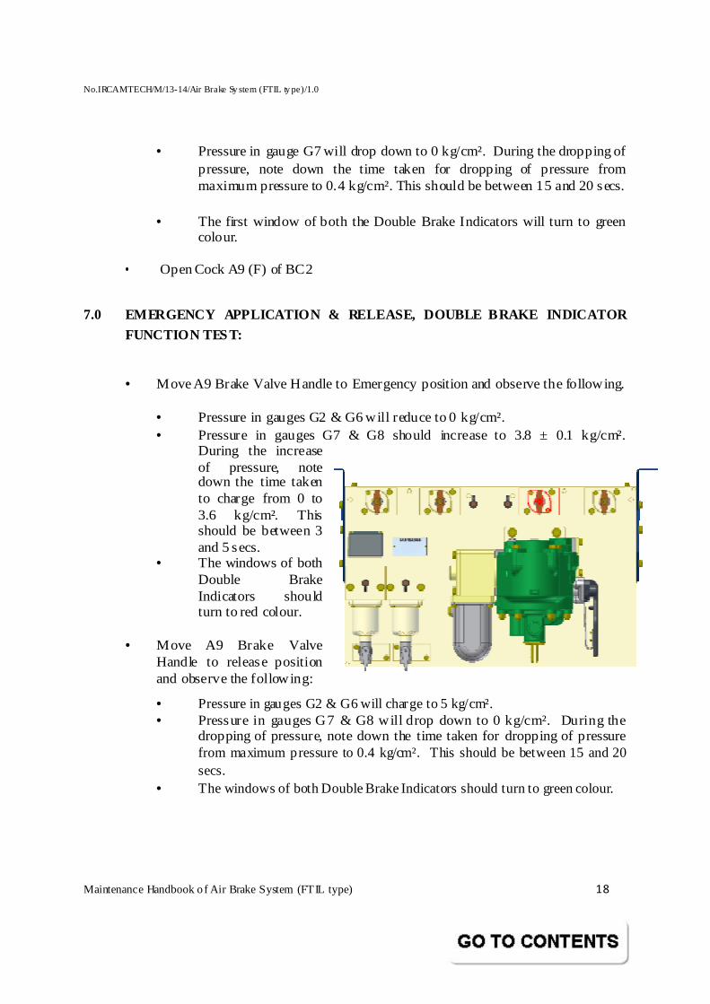
• Move A9 Brake Valve Handle to Emergency position and observe the following.
• Pressure in gauges G2 & G6 will reduce to 0 kg/cm². • Pressure in gauges G7 & G8 should increase to 3.8 ± 0.1 kg/cm².
During the increase of pressure, note down the time taken to charge from 0 to 3.6 kg/cm². This should be between 3 and 5 secs.
• The windows of both Double Brake Indicators should turn to red colour.
• Move A9 Brake Valve
Handle to release position and observe the following:
• Pressure in gauges G2 & G6 will charge to 5 kg/cm². • Pressure in gauges G7 & G8 will drop down to 0 kg/cm². During the
dropping of pressure, note down the time taken for dropping of pressure from maximum pressure to 0.4 kg/cm². This should be between 15 and 20 secs.
• The windows of both Double Brake Indicators should turn to green colour.
No.IRCAMTECH/M/13-14/Air Brake Sy stem (FTIL ty pe)/1.0
Maintenance Handbook o f Air Brake System (FTIL type) 19
8. 0 OVERCHARGE PROTECTION TEST:
• Move A9 Brake Valve Handle to emergency position. On gauges G2 & G6, pressure will reduce to 0 kg/cm². On gauges G7 and G8, it will rise to 3.8 ± 0.1 kg/cm².
• Close Cock C10. • Open Cock C3. Gauge G6 will rise to 6 kg/cm². Gauges G7 and G8 will begin to
fall. Note that the pressure in the CR at test point gauge [A14 (F)]. It should not get overcharged within 10 secs. The timing should be started at once the Cock C3 is opened.
• Close Cock C3. Move A9 Brake Valve Handle to release position and open
Cock C10.Gauge G6 will read 5 kg/cm². Meanwhile the pressure in CR also will fall to 5 kg/cm² (if not pull the DV Operating Lever briefly to bring it to 5 kg/cm²).
• Pull the Operating Lever of the DV quickly for 1 sec. The pressure in CR
should not drop. Even if it drops it should charge back to 5 kg/cm².
9.0 PARTIAL BRAKING TEST:
• Move A9 Brake Valve Handle to full-service application position. Pressure in gauges G7 & G8 should increase to 3.8 ± 0.1 kg/cm².
• Pull the Operating Lever briefly. Pressure in Gauges G7 & G8 will drop and
stabilize (BC pressure should not drop more than 1 kg/cm² from maximum pressure).
• Move A9 Brake Valve Handle to release position. Pressure in gauges G2 & G6
will charge back to 5 kg/cm².
10.0 SENSITIVITY TEST:
• Close Cock C2. Fit a Choke in Cock V3 to reduce the pressure in gauge G6 at the rate of 0.6 kg/cm² in 6 secs. The pressure in gauges G7 & G8 should start to rise within 6 secs.
• Close Cock V3 and open Cock C2. Gauges G6 should charge back t o 5
kg/cm².
No.IRCAMTECH/M/13-14/Air Brake Sy stem (FTIL ty pe)/1.0
Maintenance Handbook o f Air Brake System (FTIL type) 20
11.0 INSENSITIVITY TEST:
• Close Cock C2. Fit a Choke in Cock V3 to reduce the pressure in gauge G6 at the rate of 0.4 kg/cm² in 60 secs. Gauges G7 & G8 should not rise.
• Close Cock V3 and remove the Choke.
12.0 RE-FEEDING TEST:
• Open Cock C2. Fit a 2 mm Choke in Cock V6. Move A9 Brake Valve to Full service application position. The pressure in gauges G7 & G8 will rise to 3.8 ± 0.1 kg/cm². Now open Cock V6. The pressure in gauge G7 will drop initially and stabilise. Close Cock V6 and remove the Choke from Cock V6 and screw into Cock V5. Open Cock V5. The pressure in gauge G8 will drop initially and stabilise. Close Cock V5. Move A9 Brake Valve Handle to release position.
13.0 GRADUATED APPLICATION & RELEASE:
• Brake Cylinder pressure increase should be attained when Brake Pipe pressure is reduced in steps. The reduction in BP pressure can be observed in gauge G6 by opening Cock V3 after closing Cock C2. The BC pressure increase can be seen in gauges G7 & G8.
• Close Cock V3 and op en Cock C2 slowly and partly for checking the graduated release during which gauge G6 will show an increase in reading and gauges G7 & G8 will fall in pressures.
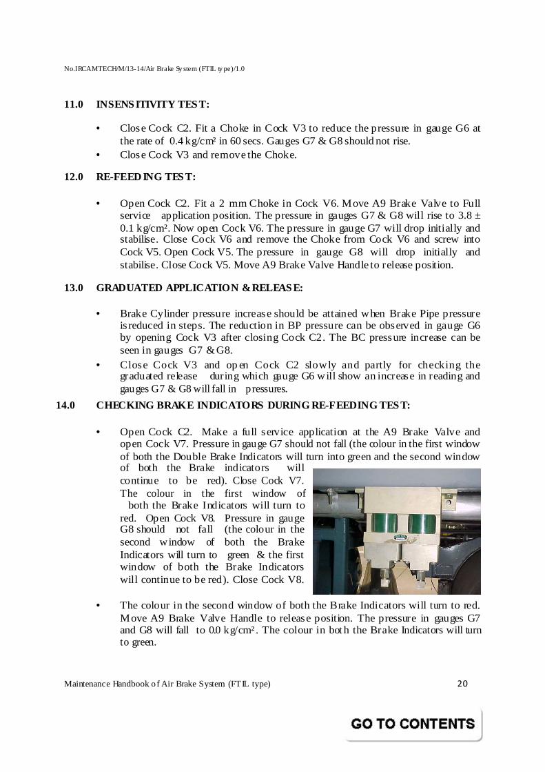
14.0 CHECKING BRAKE INDICATORS DURING RE-FEEDING T EST:
• Open Cock C2. Make a full service application at the A9 Brake Valve and open Cock V7. Pressure in gauge G7 should not fall (the colour in the first window of both the Double Brake Indicators will turn into green and the second window of both the Brake indicators will continue to be red). Close Cock V7. The colour in the first window of both the Brake Indicators will turn to red. Open Cock V8. Pressure in gauge G8 should not fall (the colour in the second window of both the Brake Indicators will turn to green & the first window of both the Brake Indicators will continue to be red). Close Cock V8.
• The colour in the second window of both the Brake Indicators will turn to red.
Move A9 Brake Valve Handle to release position. The pressure in gauges G7 and G8 will fall to 0.0 kg/cm². The colour in both the Brake Indicators will turn to green.
No.IRCAMTECH/M/13-14/Air Brake Sy stem (FTIL ty pe)/1.0
Maintenance Handbook o f Air Brake System (FTIL type) 21
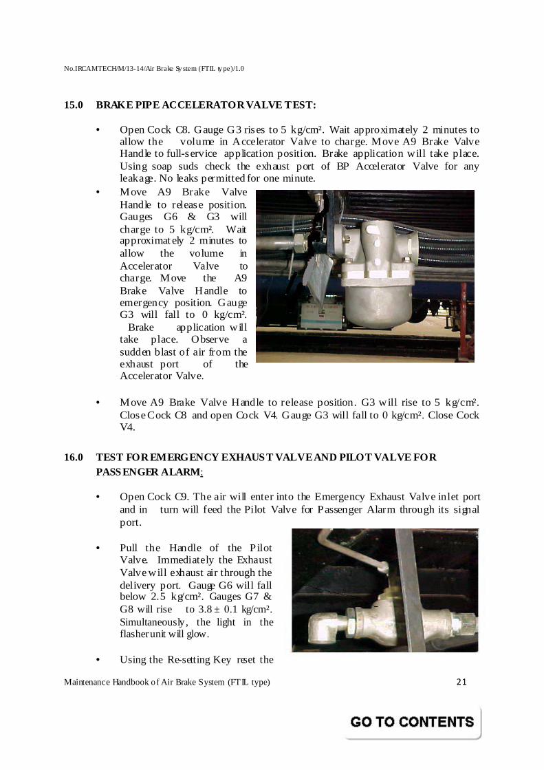
15.0 BRAKE PIPE ACCELERATOR VALVE TEST:
• Open Cock C8. Gauge G3 rises to 5 kg/cm². Wait approximately 2 minutes to allow the volume in Accelerator Valve to charge. Move A9 Brake Valve Handle to full-service application position. Brake application will take place. Using soap suds check the exhaust port of BP Accelerator Valve for any leakage. No leaks permitted for one minute.
• Move A9 Brake Valve Handle to release position. Gauges G6 & G3 will charge to 5 kg/cm². Wait approximately 2 minutes to allow the volume in Accelerator Valve to charge. Move the A9 Brake Valve Handle to emergency position. Gauge G3 will fall to 0 kg/cm². Brake application will take place. Observe a sudden blast of air from the exhaust port of the Accelerator Valve.
• Move A9 Brake Valve Handle to release position. G3 will rise to 5 kg/cm².
Close Cock C8 and open Cock V4. Gauge G3 will fall to 0 kg/cm². Close Cock V4.
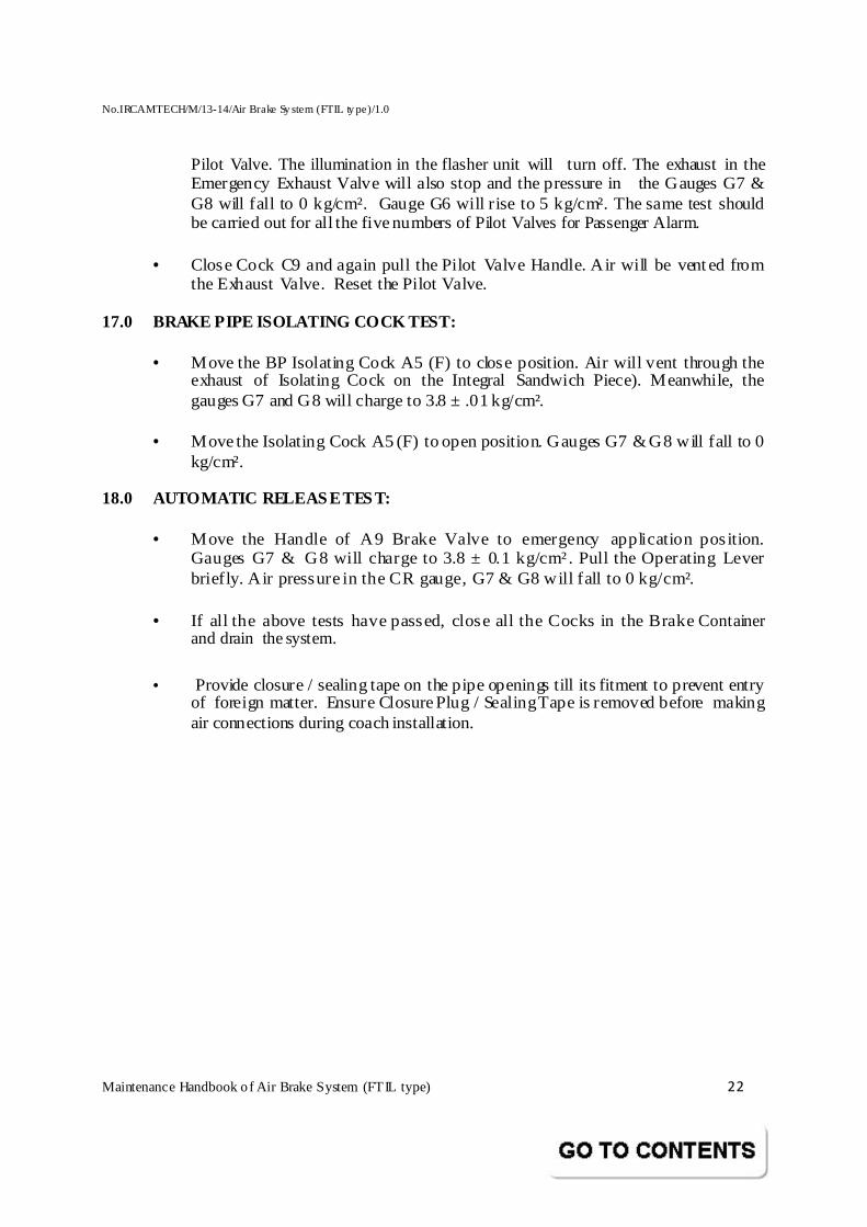
16.0 TEST FOR EMERGENCY EXHAUST VALVE AND PILOT VAL VE FOR PASSENGER ALARM:
• Open Cock C9. The air will enter into the Emergency Exhaust Valve inlet port and in turn will feed the Pilot Valve for Passenger Alarm through its signal port.
• Pull the Handle of the Pilot
Valve. Immediately the Exhaust Valve will exhaust air through the delivery port. Gauge G6 will fall below 2.5 kg/cm². Gauges G7 & G8 will rise to 3.8 ± 0.1 kg/cm². Simultaneously, the light in the flasher unit will glow.
• Using the Re-setting Key reset the
No.IRCAMTECH/M/13-14/Air Brake Sy stem (FTIL ty pe)/1.0
Maintenance Handbook o f Air Brake System (FTIL type) 22
Pilot Valve. The illumination in the flasher unit will turn off. The exhaust in the Emergency Exhaust Valve will also stop and the pressure in the Gauges G7 & G8 will fall to 0 kg/cm². Gauge G6 will r ise to 5 kg/cm². The same test should be carried out for all the five numbers of Pilot Valves for Passenger Alarm.
• Close Cock C9 and again pull the Pilot Valve Handle. Air will be vented from
the Exhaust Valve. Reset the Pilot Valve.
17.0 BRAKE PIPE ISOLATING COCK TEST:
• Move the BP Isolating Cock A5 (F) to close position. Air will vent through the exhaust of Isolating Cock on the Integral Sandwich Piece). Meanwhile, the gauges G7 and G8 will charge to 3.8 ± .01 kg/cm².
• Move the Isolating Cock A5 (F) to open position. Gauges G7 & G8 will fall to 0
kg/cm².
18.0 AUTOMATIC RELEASE TEST:
• Move the Handle of A9 Brake Valve to emergency application position. Gauges G7 & G8 will charge to 3.8 ± 0.1 kg/cm². Pull the Operating Lever briefly. Air pressure in the CR gauge, G7 & G8 will fall to 0 kg/cm².
• If all the above tests have passed, close all the Cocks in the Brake Container
and drain the system.
• Provide closure / sealing tape on the pipe openings till its fitment to prevent entry of foreign matter. Ensure Closure Plug / Sealing Tape is removed before making air connections during coach installation.
No.IRCAMTECH/M/13-14/Air Brake Sy stem (FTIL ty pe)/1.0
Maintenance Handbook o f Air Brake System (FTIL type) 23
No.IRCAMTECH/M/13-14/Air Brake Sy stem (FTIL ty pe)/1.0
Maintenance Handbook o f Air Brake System (FTIL type) 24
No.IRCAMTECH/M/13-14/Air Brake Sy stem (FTIL ty pe)/1.0
Maintenance Handbook o f Air Brake System (FTIL type) 25
No.IRCAMTECH/M/13-14/Air Brake Sy stem (FTIL ty pe)/1.0
Maintenance Handbook o f Air Brake System (FTIL type) 26
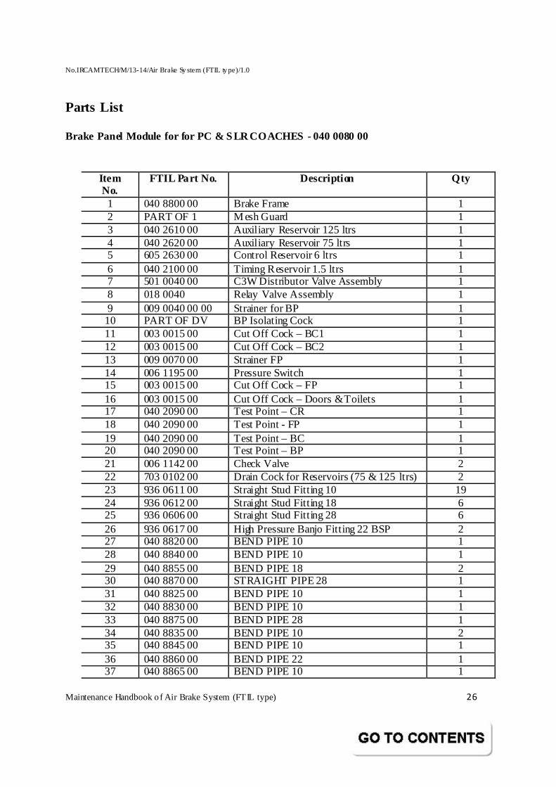
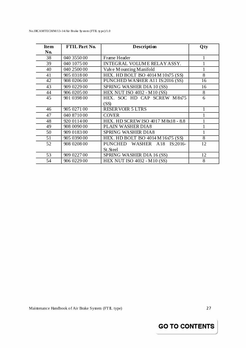
Parts List
Brake Panel Module for for PC & SLR COACHES - 040 0080 00
Item No.
FTIL Part No. Description Qty
1 040 8800 00 Brake Frame 1 2 PART OF 1 M esh Guard 1 3 040 2610 00 Auxiliary Reservoir 125 ltrs 1 4 040 2620 00 Auxiliary Reservoir 75 ltrs 1 5 605 2630 00 Control Reservoir 6 ltrs 1 6 040 2100 00 Timing Reservoir 1.5 ltrs 1 7 501 0040 00 C3W Distributor Valve Assembly 1 8 018 0040 Relay Valve Assembly 1 9 009 0040 00 00 Strainer for BP 1 10 PART OF DV BP Isolating Cock 1 11 003 0015 00 Cut Off Cock – BC1 1 12 003 0015 00 Cut Off Cock – BC2 1 13 009 0070 00 Strainer FP 1 14 006 1195 00 Pressure Switch 1 15 003 0015 00 Cut Off Cock – FP 1 16 003 0015 00 Cut Off Cock – Doors & Toilets 1 17 040 2090 00 Test Point – CR 1 18 040 2090 00 Test Point - FP 1 19 040 2090 00 Test Point – BC 1 20 040 2090 00 Test Point – BP 1 21 006 1142 00 Check Valve 2 22 703 0102 00 Drain Cock for Reservoirs (75 & 125 ltrs) 2 23 936 0611 00 Straight Stud Fitting 10 19 24 936 0612 00 Straight Stud Fitting 18 6 25 936 0606 00 Straight Stud Fitting 28 6 26 936 0617 00 High Pressure Banjo Fitting 22 BSP 2 27 040 8820 00 BEND PIPE 10 1 28 040 8840 00 BEND PIPE 10 1 29 040 8855 00 BEND PIPE 18 2 30 040 8870 00 STRAIGHT PIPE 28 1 31 040 8825 00 BEND PIPE 10 1 32 040 8830 00 BEND PIPE 10 1 33 040 8875 00 BEND PIPE 28 1 34 040 8835 00 BEND PIPE 10 2 35 040 8845 00 BEND PIPE 10 1 36 040 8860 00 BEND PIPE 22 1 37 040 8865 00 BEND PIPE 10 1
No.IRCAMTECH/M/13-14/Air Brake Sy stem (FTIL ty pe)/1.0
Maintenance Handbook o f Air Brake System (FTIL type) 27
Item No.
FTIL Part No. Description Qty
38 040 3550 00 Frame Header 1 39 040 1075 00 INTEGRAL VOLUM E RELAY ASSY. 1 40 040 2500 00 Valve M ounting Manifold 1 41 905 0318 00 HEX. HD BOLT ISO 4014 M 10x75 (SS) 8 42 908 0206 00 PUNCHED WASHER A11 IS:2016 (SS) 16 43 909 0229 00 SPRING WASHER DIA 10 (SS) 16 44 906 0205 00 HEX NUT ISO 4032 - M10 (SS) 8 45 901 0398 00 HEX. SOC HD CAP SCREW M 8x75
(SS) 6
46 905 0271 00 RESERVOIR 5 LTRS 1 47 040 8710 00 COVER 1 48 920 0114 00 HEX. HD SCREW ISO 4017 M 8x18 - 8.8 1 49 908 0090 00 PLAIN WASHER DIA8 1 50 909 0183 00 SPRING WASHER DIA8 1 51 905 0390 00 HEX. HD BOLT ISO 4014 M 16x75 (SS) 8 52 908 0208 00 PUNCHED WASHER A18 IS:2016-
St.Steel 12
53 909 0227 00 SPRING WASHER DIA 16 (SS) 12 54 906 0229 00 HEX NUT ISO 4032 - M10 (SS) 8
No.IRCAMTECH/M/13-14/Air Brake Sy stem (FTIL ty pe)/1.0
Maintenance Handbook o f Air Brake System (FTIL type) 28
Parts List
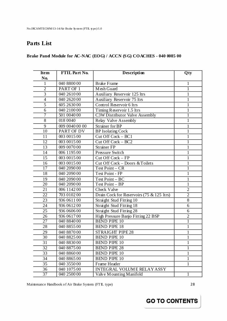
Brake Panel Module for AC-NAC (EOG) / ACCN (SG) COACHES - 040 0085 00
Item No.
FTIL Part No. Description Qty
1 040 8800 00 Brake Frame 1 2 PART OF 1 M esh Guard 1 3 040 2610 00 Auxiliary Reservoir 125 ltrs 1 4 040 2620 00 Auxiliary Reservoir 75 ltrs 1 5 605 2630 00 Control Reservoir 6 ltrs 1 6 040 2100 00 Timing Reservoir 1.5 ltrs 1 7 501 0040 00 C3W Distributor Valve Assembly 1 8 018 0040 Relay Valve Assembly 1 9 009 0040 00 00 Strainer for BP 1 10 PART OF DV BP Isolating Cock 1 11 003 0015 00 Cut Off Cock – BC1 1 12 003 0015 00 Cut Off Cock – BC2 1 13 009 0070 00 Strainer FP 1 14 006 1195 00 Pressure Switch 1 15 003 0015 00 Cut Off Cock – FP 1 16 003 0015 00 Cut Off Cock – Doors & Toilets 1 17 040 2090 00 Test Point – CR 1 18 040 2090 00 Test Point - FP 1 19 040 2090 00 Test Point – BC 1 20 040 2090 00 Test Point – BP 1 21 006 1142 00 Check Valve 2 22 703 0102 00 Drain Cock for Reservoirs (75 & 125 ltrs) 2 23 936 0611 00 Straight Stud Fitting 10 8 24 936 0612 00 Straight Stud Fitting 18 6 25 936 0606 00 Straight Stud Fitting 28 6 26 936 0617 00 High Pressure Banjo Fitting 22 BSP 2 27 040 8840 00 BEND PIPE 10 1 28 040 8855 00 BEND PIPE 18 1 29 040 8870 00 STRAIGHT PIPE 28 1 30 040 8825 00 BEND PIPE 10 1 31 040 8830 00 BEND PIPE 10 1 32 040 8875 00 BEND PIPE 28 1 33 040 8860 00 BEND PIPE 10 1 34 040 8865 00 BEND PIPE 10 1 35 040 3550 00 Frame Header 1 36 040 1075 00 INTEGRAL VOLUM E RELAY ASSY 37 040 2500 00 Valve M ounting Manifold 1
No.IRCAMTECH/M/13-14/Air Brake Sy stem (FTIL ty pe)/1.0
Maintenance Handbook o f Air Brake System (FTIL type) 29
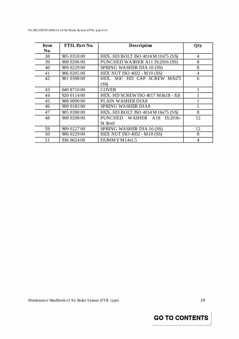
Item No.
FTIL Part No. Description Qty
38 905 0318 00 HEX. HD BOLT ISO 4014 M 10x75 (SS) 4 39 908 0206 00 PUNCHED WASHER A11 IS:2016 (SS) 8 40 909 0229 00 SPRING WASHER DIA 10 (SS) 8 41 906 0205 00 HEX NUT ISO 4032 - M10 (SS) 4 42 901 0398 00 HEX. SOC HD CAP SCREW M 8x75
(SS) 6
43 040 8710 00 COVER 1 44 920 0114 00 HEX. HD SCREW ISO 4017 M 8x18 - 8.8 1 45 908 0090 00 PLAIN WASHER DIA8 1 46 909 0183 00 SPRING WASHER DIA8 1 47 905 0390 00 HEX. HD BOLT ISO 4014 M 16x75 (SS) 8 48 908 0208 00 PUNCHED WASHER A18 IS:2016-
St.Steel 12
59 909 0227 00 SPRING WASHER DIA 16 (SS) 12 50 906 0229 00 HEX NUT ISO 4032 - M10 (SS) 8 51 936 0624 00 DUMM Y M14x1.5 4
No.IRCAMTECH/M/13-14/Air Brake Sy stem (FTIL ty pe)/1.0
Maintenance Handbook o f Air Brake System (FTIL type) 30
5.2 BRAKE PANEL (A1)
5.2.1 INTRODUCTION
The Brake Panel provided in the Brake panel module (Brake Frame) serves to mount comp actly t he brake and air system equip ment other than located at special places in the Coach. The schematic drg of the Brake Panel portion with its devices is indicated by a dotted square in the overall schemat ic of the Coaching brake system. The list of equipment contained in the Panel is indicated in the part no. drg / parts list attached.
5.2.2 CONSTRUCTION
The brake frame comprises a valve mounting manifold to which components and subassemblies are attached. The components are positioned in convenient and compact groups and pneumatic interconnections are formed by drilling within the valve mounting manifold.
The valve mounting manifold is constructed from high grade aluminium alloy which is anodized after machining.
All pneumatic assemblies are constructed from corrosion resistant aluminium alloy and with internal components, e.g. Valve Stems, Springs, etc., of Stainless Steel. Valve Finished faces are of hard synthetic rubber with ground faces. The Valves are operated by means of self-seating moulded synthetic rubber Diap hragms, which are fully supported over their working surfaces. Components are mounted to the outer face of a valve mounting manifold using O Ring Joints to seal the interface connections. A Header mounted at the top of the Brake Panel forms an interface connection wit h the Header of Brake Container of the Coach pneumat ic system. This is indicated in the part identification given in the drawings.
5.2.3 LOCATION OF COMPONENTS The physical location of all the components on the progressive three p anels is shown in the respective part drawings attached.
Port identification for the input / output air connections with the Brake Container is also indicated in the p art drgs. In addit ion, t est points wherever required are indicated.
No.IRCAMTECH/M/13-14/Air Brake Sy stem (FTIL ty pe)/1.0
Maintenance Handbook o f Air Brake System (FTIL type) 31
5.2.4 INSTALLATION
The Brake Panel compris ing the pneumat ic system with pre-tested component installed in position has to be secured to the Brake Container.
The Brake Panel Header has to be connected with air pipelines as indicated in the port identif ication specified in the drawing.
The electrical connections from the Coaching circuit is to be given for the Pressure Switch (A10) separately.
5.2.5 TESTING AFTER INSTALLATION
As the Brake Panel forms part of Brake Container assembly, no separate test procedure is required since it is included in the Brake Container testing.
No.IRCAMTECH/M/13-14/Air Brake Sy stem (FTIL ty pe)/1.0
Maintenance Handbook o f Air Brake System (FTIL type) 32
5.3 DISTRIBUTOR VALVE (FTIL Make)
5.3.1 INTRODUCTION
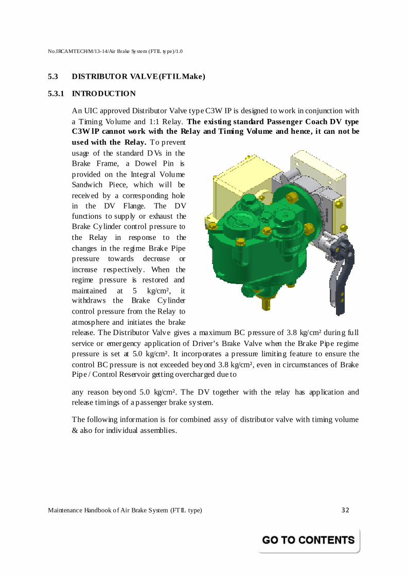
An UIC approved Distributor Valve type C3W IP is designed to work in conjunction with a Timing Volume and 1:1 Relay. The existing standard Passenger Coach DV type C3W lP cannot work with the Relay and Timing Volume and hence, it can not be used with the Relay. To prevent usage of the standard DVs in the Brake Frame, a Dowel Pin is provided on the Integral Volume Sandwich Piece, which will be received by a corresponding hole in the DV Flange. The DV functions to supply or exhaust the Brake Cylinder control pressure to the Relay in response to the changes in the regime Brake Pipe pressure towards decrease or increase respectively. When the regime pressure is restored and maintained at 5 kg/cm², it withdraws the Brake Cylinder control pressure from the Relay to atmosphere and initiates the brake release. The Distributor Valve gives a maximum BC pressure of 3.8 kg/cm² during fu ll service or emergency application of Driver’s Brake Valve when the Brake Pipe regime pressure is set at 5.0 kg/cm². It incorporates a pressure limiting feature to ensure the control BC pressure is not exceeded beyond 3.8 kg/cm², even in circumstances of Brake Pipe / Control Reservoir getting overcharged due to
any reason beyond 5.0 kg/cm². The DV together with the relay has application and release timings of a passenger brake system.
The following information is for combined assy of distributor valve with timing volume & also for indiv idual assemblies.
No.IRCAMTECH/M/13-14/Air Brake Sy stem (FTIL ty pe)/1.0
Maintenance Handbook o f Air Brake System (FTIL type) 33
No.IRCAMTECH/M/13-14/Air Brake Sy stem (FTIL ty pe)/1.0
Maintenance Handbook o f Air Brake System (FTIL type) 34
5.3.2 GENERAL
This C3W Distributor Valve meets all the specifications laid down by UIC / RDSO and offers security, sensitivity and reliability for application to air brake system of LHB Coaches. The C3W Distributor Valve is of graduated release type.
5.3.3 MAIN CHARACTERISTICS
General Features of C3w Distributor Valve
� Compact and sturdy in construction. � High Sensitivity � Step less graduation in brake application and release � High speed of propagation � M aximum Brake Cylinder Pressure Limiting Device, independent of the BP regime
pressure in case of Passenger Distributor Valve. � Easy access to Chokes for cleaning and replacement. � Confirms to UIC / RDSO specifications of graduated release Air brake system � Suitable for both single pipe and twin pipe Air Brake System.
5.3.4 PERFORMANCE
The speed of propagation is in the order of 280 m / sec and is obtained by provision of a Quick Service Valve.
The brake is applied within 1.2 sec when Brake Pipe pressure drop is 0.6 bar in 6 secs (UIC No. 547).
The brake does not apply when Brake Pipe pressure drop is less than 0.3 bar in 60 secs. (UIC No. 547).
After full braking, Brake Pipe pressure can be increased to 6 bar with a view to obtain a faster brake release and a protective feature in Distributor Valve prevents the danger of overcharge of the Control Reservoirs from 5.0 Kg/cm2 to 6 bar for a period of 25 secs min.
Brake application and release graduations of 0.1 bar are possible.
If the Brake Pipe regime pressure is set at 5.0 Kg/cm2 , the Distributor Valve restricts Brake Cylinder pressure to 3.8 ± 0.1 bar max, irrespective of the drop in Brake Pipe pressure or the Auxiliary Reservoir air pressure (provided it is sufficiently at a higher pressure than 3.8 bar even after repeated brake application in a single pipe system). However, after a brake application is made, full brake release is not achievable till the Brake Pipe pressure builds up to 4.85 bar.
No.IRCAMTECH/M/13-14/Air Brake Sy stem (FTIL ty pe)/1.0
Maintenance Handbook o f Air Brake System (FTIL type) 35
Provision is made for release of brake on the vehicle (manual release) when brakes are fully applied. This is especially useful in marshalling operation by venting Control Reservoir air pressure. It is also possible to vent all the brake equipment air pressure fully. To operate this feature, the handle of Isolating cock on Sandwich Piece is to be moved to the close position and the release lever of the Distributor valve pulled brief ly.
CAUTION
1) Mere closing of Isolating Cock does not Release the brake in the vehicle.
2) For complete venting of the system including the Auxiliary Reservoir, the Release lever should be held in pulled condition till the air exhaust stops.
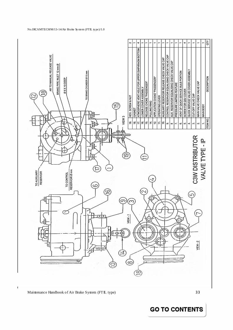
5.3.5 DESCRIPTION OF DISTRIBUTOR VALVE
The Distributor Valve has air p ipe connections to
Brake pipe (BP)
Auxiliary Reservoir (AR)
Control Reservoir (CR)
Brake Cylinder (BC)
The Distributor valve consists of major sub assemblies housed in a Body with
their functions as under:
M ain Valve
Cut off valve
Quick Service Valve
Auxiliary Reservoir Check Valve
Inshot valve
Application and release chokes
Double release valve
No.IRCAMTECH/M/13-14/Air Brake Sy stem (FTIL ty pe)/1.0
Maintenance Handbook o f Air Brake System (FTIL type) 36
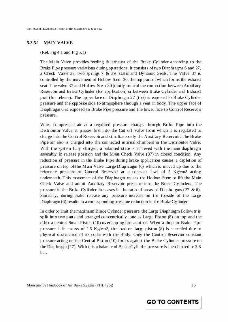
5.3.5.1 MAIN VALVE
(Ref. Fig 4.1 and Fig 5.1)
The M ain Valve provides feeding & exhaust of the Brake Cylinder according to the Brake Pipe pressure variations during operations. It consists of two Diaphragms 6 and 27, a Check Valve 37, two springs 7 & 39, static and Dynamic Seals. The Valve 37 is controlled by the movement of Hollow Stem 30, the top part of which forms the exhaust seat. The valve 37 and Hollow Stem 30 jointly control the connection between Auxiliary Reservoir and Brake Cylinder (for application) or between Brake Cylinder and Exhaust port (for release). The upper face of Diaphragm 27 (top) is exposed to Brake Cylinder pressure and the opposite side to atmosphere through a vent in body. The upper face of Diaphragm 6 is exposed to Brake Pipe pressure and the lower face to Control Reservoir pressure.
When compressed air at a regulated pressure charges through Brake Pipe into the Distributor Valve, it passes first into the Cut off Valve from which it is regulated to charge into the Control Reservoir and simultaneously the Auxiliary Reservoir. The Brake Pipe air also is charged into the connected internal chambers in the Distributor Valve. With the system fully charged, a balanced state is achieved with the main diaphragm assembly in release position and the M ain Check Valve (37) in closed condition. Any reduction of pressure in the Brake Pipe during brake application causes a depletion of pressure on top of the M ain Valve Large Diaphragm (6) which is moved up due to the reference pressure of Control Reservoir at a constant level of 5 Kg/cm2 acting underneath. This movement of the Diaphragm causes the Hollow Stem to lift the Main Check Valve and admit Auxiliary Reservoir pressure into the Brake Cylinders. The pressure in the Brake Cylinder increases in the ratio of areas of Diaphragms (27 & 6). Similar ly, during brake release any pressure increase on the topside of the Large Diaphragm (6) results in a corresponding pressure reduction in the Brake Cylinder.
In order to limit the maximum Brake Cylinder pressure, the Large Diaphragm Follower is split into two parts and arranged concentrically, one as Large Piston (8) on top and the other a central Small Piston (10) overlapping one another. When a drop in Brake Pipe pressure is in excess of 1.5 Kg/cm2, the load on large piston (8) is cancelled due to physical obstruction of its collar with the Body. Only the Control Reservoir constant pressure acting on the Central Piston (10) forces against the Brake Cylinder pressure on the Diaphragm (27). With this a balance of Brake Cylinder pressure is then limited to 3.8 bar.
No.IRCAMTECH/M/13-14/Air Brake Sy stem (FTIL ty pe)/1.0
Maintenance Handbook o f Air Brake System (FTIL type) 37
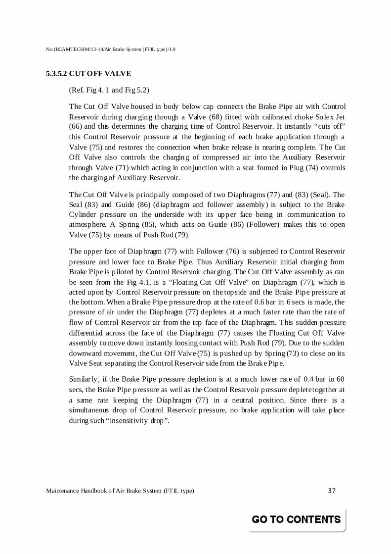
5.3.5.2 CUT OFF VALVE
(Ref. Fig 4. 1 and Fig 5.2)
The Cut Off Valve housed in body below cap connects the Brake Pipe air with Control Reservoir during charging through a Valve (68) fitted with calibrated choke Solex Jet (66) and this determines the charging time of Control Reservoir. It instantly “cuts off” this Control Reservoir pressure at the beginning of each brake application through a Valve (75) and restores the connection when brake release is nearing complete. The Cut Off Valve also controls the charging of compressed air into the Auxiliary Reservoir through Valve (71) which acting in conjunction with a seat formed in Plug (74) controls the charging of Auxiliary Reservoir.
The Cut Off Valve is principally composed of two Diaphragms (77) and (83) (Seal). The Seal (83) and Guide (86) (diaphragm and follower assembly) is subject to the Brake Cylinder pressure on the underside with its upper face being in communication to atmosphere. A Spring (85), which acts on Guide (86) (Follower) makes this to open Valve (75) by means of Push Rod (79).
The upper face of Diaphragm (77) with Follower (76) is subjected to Control Reservoir pressure and lower face to Brake Pipe. Thus Auxiliary Reservoir initial charging from Brake Pipe is piloted by Control Reservoir charging. The Cut Off Valve assembly as can be seen from the Fig 4.1, is a “Floating Cut Off Valve” on Diaphragm (77), which is acted upon by Control Reservoir pressure on the topside and the Brake Pipe pressure at the bottom. When a Brake Pipe pressure drop at the rate of 0.6 bar in 6 secs is made, the pressure of air under the Diaphragm (77) depletes at a much faster rate than the rate of flow of Control Reservoir air from the top face of the Diaphragm. This sudden pressure differential across the face of the Diaphragm (77) causes the Floating Cut Off Valve assembly to move down instantly loosing contact with Push Rod (79). Due to the sudden downward movement, the Cut Off Valve (75) is pushed up by Spring (73) to close on its Valve Seat separating the Control Reservoir side from the Brake Pipe.
Similar ly, if the Brake Pipe pressure depletion is at a much lower rate of 0.4 bar in 60 secs, the Brake Pipe pressure as well as the Control Reservoir pressure deplete together at a same rate keeping the Diaphragm (77) in a neutral position. Since there is a simultaneous drop of Control Reservoir pressure, no brake application will take place during such “insensitivity drop”.
No.IRCAMTECH/M/13-14/Air Brake Sy stem (FTIL ty pe)/1.0
Maintenance Handbook o f Air Brake System (FTIL type) 38
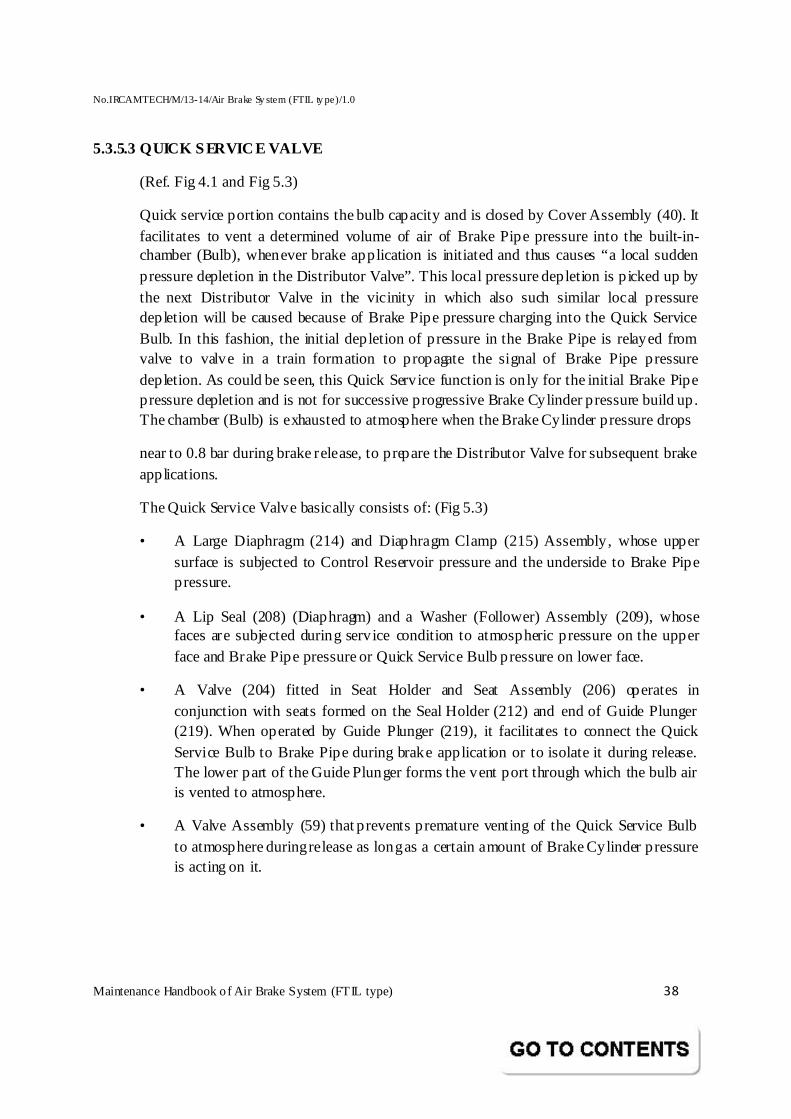
5.3.5.3 QUICK SERVICE VALVE
(Ref. Fig 4.1 and Fig 5.3)
Quick service portion contains the bulb capacity and is closed by Cover Assembly (40). It facilitates to vent a determined volume of air of Brake Pipe pressure into the built-in-chamber (Bulb), whenever brake application is initiated and thus causes “a local sudden pressure depletion in the Distributor Valve”. This local pressure depletion is p icked up by the next Distributor Valve in the vicinity in which also such similar local pressure depletion will be caused because of Brake Pipe pressure charging into the Quick Service Bulb. In this fashion, the initial depletion of pressure in the Brake Pipe is relayed from valve to valve in a train formation to propagate the signal of Brake Pipe pressure depletion. As could be seen, this Quick Service function is only for the initial Brake Pipe pressure depletion and is not for successive progressive Brake Cylinder pressure build up. The chamber (Bulb) is exhausted to atmosphere when the Brake Cylinder pressure drops
near to 0.8 bar during brake release, to prepare the Distributor Valve for subsequent brake applications.
The Quick Service Valve basically consists of: (Fig 5.3)
• A Large Diaphragm (214) and Diaphragm Clamp (215) Assembly, whose upper surface is subjected to Control Reservoir pressure and the underside to Brake Pipe pressure.
• A Lip Seal (208) (Diaphragm) and a Washer (Follower) Assembly (209), whose faces are subjected during service condition to atmospheric pressure on the upper face and Brake Pipe pressure or Quick Service Bulb pressure on lower face.
• A Valve (204) fitted in Seat Holder and Seat Assembly (206) operates in conjunction with seats formed on the Seal Holder (212) and end of Guide Plunger (219). When operated by Guide Plunger (219), it facilitates to connect the Quick Service Bulb to Brake Pipe during brake application or to isolate it during release. The lower part of the Guide Plunger forms the vent port through which the bulb air is vented to atmosphere.
• A Valve Assembly (59) that prevents premature venting of the Quick Service Bulb to atmosphere during release as long as a certain amount of Brake Cylinder pressure is acting on it.
No.IRCAMTECH/M/13-14/Air Brake Sy stem (FTIL ty pe)/1.0
Maintenance Handbook o f Air Brake System (FTIL type) 39
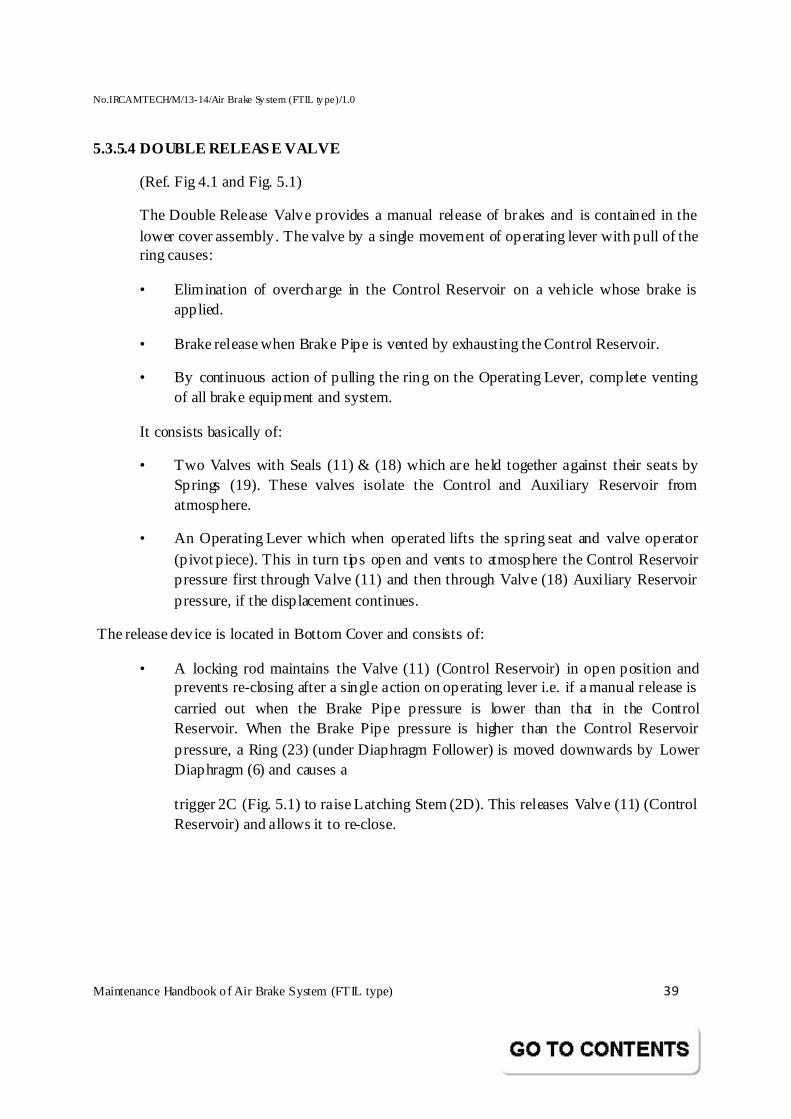
5.3.5.4 DOUBLE RELEASE VALVE
(Ref. Fig 4.1 and Fig. 5.1)
The Double Release Valve provides a manual release of brakes and is contained in the lower cover assembly. The valve by a single movement of operating lever with pull of the ring causes:
• Elimination of overcharge in the Control Reservoir on a vehicle whose brake is applied.
• Brake release when Brake Pipe is vented by exhausting the Control Reservoir.
• By continuous action of pulling the ring on the Operating Lever, complete venting of all brake equipment and system.
It consists basically of:
• Two Valves with Seals (11) & (18) which are held together against their seats by Springs (19). These valves isolate the Control and Auxiliary Reservoir from atmosphere.
• An Operating Lever which when operated lifts the spring seat and valve operator (p ivot p iece). This in turn tips open and vents to atmosphere the Control Reservoir pressure first through Valve (11) and then through Valve (18) Auxiliary Reservoir pressure, if the displacement continues.
The release device is located in Bottom Cover and consists of:
• A locking rod maintains the Valve (11) (Control Reservoir) in open position and prevents re-closing after a single action on operating lever i.e. if a manual release is carried out when the Brake Pipe pressure is lower than that in the Control Reservoir. When the Brake Pipe pressure is higher than the Control Reservoir pressure, a Ring (23) (under Diaphragm Follower) is moved downwards by Lower Diaphragm (6) and causes a
trigger 2C (Fig. 5.1) to raise Latching Stem (2D). This releases Valve (11) (Control Reservoir) and allows it to re-close.
No.IRCAMTECH/M/13-14/Air Brake Sy stem (FTIL ty pe)/1.0
Maintenance Handbook o f Air Brake System (FTIL type) 40
5.3.5.5 AUXILIARY RESERVOIR CHECK VALVE
(Ref. Fig 4.1 & Fig 5.3)
This Check Valve permits recharge of Auxiliary Reservoir and prevents any flow back towards the Brake Pipe during brake application. The Cap (44) is provided with an ‘O’ Ring (99) as a sealing joint between Body and Cap.
5.3.5 .6 PRESSURE LIMITING FEATURE
(Ref. fig 4.2 and fig 5.4)
A separate attachment is provided on top of Inshot Valve to limit the Brake Cylinder pressure not to exceed beyond 3.8 bar, under any circumstances even if the Control Reservoirs are overcharged due to any reason above 5.0 bar. The arrangement is indicated in the sketch. The Spring (712) is adjusted to regulate the Brake Cylinder pressure to 3.8 bar during DV testing. The Pressure Limiting feature is controlled by Spring (712) which constantly exerts pressure on Guide (711) downwards. Due to this, the Valve Finished (223) and Spring (709) is continuously kept pressed down in the open condition. As and when BP reduction takes place, M ain Valve is lifted allowing Auxiliary Reservoir pressure to enter the Inshot passage and passes through opening made by Valve Finished. The Auxiliary Reservoir air pressure further passes into the Brake Cylinder through the opening of Cup (710) into the bottom of Diaphragm (77). As the pressure increases under the Diaphragm, the Spring (712) assumes a position to close Valve Finished (223) on the Seat by the Spring (709), thereby cutting off the further air supply. With this feature, any pressure from Auxiliary Reservoir above 3.8 not allowed in the Brake Cylinder area.
5.3.6 OPERATION
(Ref. Fig. 4.2)
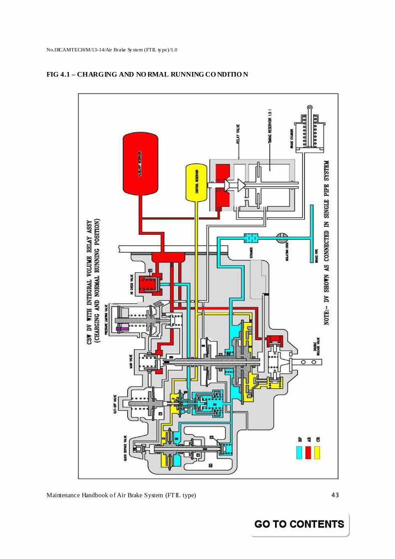
5.3.6.1 CHARGING AND RUNNING
Compressed air at 5.0 Kg/cm2 from Brake Pipe enters the following regions of Distributor Valve colored blue:
Chamber 2, the top side of Lower Large Diaphragm of Main Valve.
Chamber 7 of Cut Off Valve
Chamber 4, the lower side of the Upper Diaphragm of QSV (Quick Service Valve)
Chamber D, chamber below the inlet valve of QSV
Further, the air from chamber 7 of cut off valve charges through the Solex jet and valve (6) to fill the following regions coloured Yellow:
Chamber 1, the bottom side of Lower Large Diaphragm of M ain Valve. The top side of the Lower Diaphragm of Cut Off Valve.
Chamber 3, the top side of the Upper Diaphragm side of QSV.
No.IRCAMTECH/M/13-14/Air Brake Sy stem (FTIL ty pe)/1.0
Maintenance Handbook o f Air Brake System (FTIL type) 41
Control reservoir (CR)
In addition, the air from chamber 7 lift the Check Valve (15) to fill the Auxiliary Reservoir, coloured Red. All the chambers mentioned above are brought to the charging pressure of 5.0 Kg/cm2 . Due to the “zero pressure” differential across the Large Diaphragm of the Main Valve when Control Reservoir is fu lly charged, the Diaphragm Assembly will be in neutral position. This keeps the central passage of the Main Valve Stem (Hollow Stem 30) that leads to atmosphere, open to Brake Cylinder, as a gap by design will prevail between M ain Valve Check Valve (37) and Hollow Stem end at top.
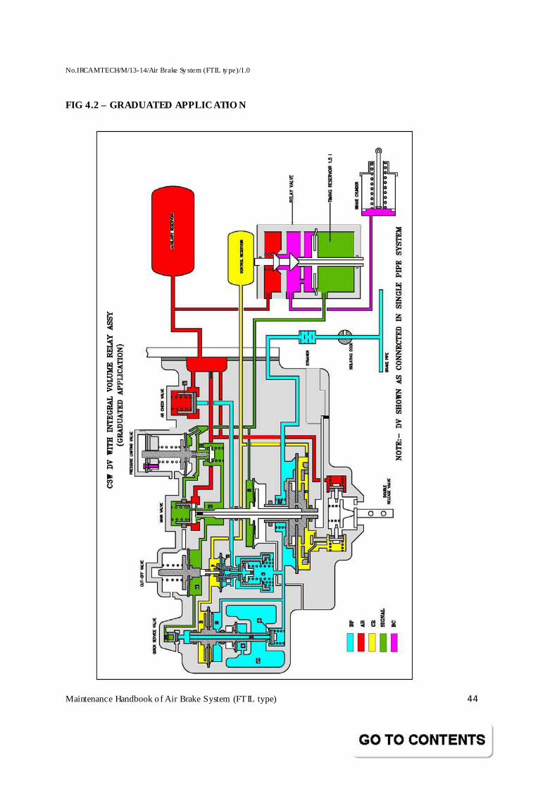
5.3.6.2 GRADUATED APPLICATION
When a reduction in BP pressure is caused by the Driver’s Brake Valve, the air pressure under the Diaphragm in chamber 5 of Cut Off Valve drops quickly. This makes the Diaphragm to flex down and closes the passage to the Control Reservoir, thus isolating it from BP. Due to the isolation of Control Reservoir in chambers 1 & 2 of Main Valve portion, a pressure difference is set across the Bottom Diaphragm (6) separating these two chambers causing a lift of the Hollow Stem to open the Inlet Valve (Main Check Valve). Then, air from Auxiliary Reservoir will flow into chamber 9 from where it is led into chambers 11 (Cut Off Valve portion) and 16 (QSV portion) and also to the bottom side of Inshot Valve. In chamber 11, the air pressure builds up under Diaphragm and lifts up, thereby withdrawing the Pin from Valve (6). In In shot Valve, air passes through the valve opening and also through “Application Choke” into Brake Cylinder.
This sudden rush of air into the Brake Cylinder will help to bring the brake rigging / shoes quickly to position. Air also enters chamber 10 and lifts the Diaphragm of Inshot Valve and closes the valve passage. A pressure of about 0.5 ± 0.2 bar is enough to close the Inshot Valve passage. Once this passage is closed, air flows only through the Application Choke into the Brake Cylinder. In chamber 8 on top of the Upper Diaphragm of the M ain Valve, the Brake Cylinder pressure builds up bringing the Diaphragm Assembly downwards and finally bringing the Inlet Check Valve to lap position. As soon as the balance is reached in this Diaphragm Assembly, no more air can flow into Brake Cylinder. Similarly, every time the Brake Pipe pressure is reduced in steps, the phenomenon will repeat and air from Auxiliary Reservoir will gradually flow into Brake Cylinder in corresponding steps. In case of full service application OR an emergency application, the maximum Brake Cylinder pressure that is required to balance the main valve diaphragm assembly is 3.8 ± 0.1 bar with Brake Pipe regime pressure set at 5.0 Kg/cm2 .
5.3.6.3 QUICK SERVICE APPLICATION
As soon as the Brake Pipe pressure is reduced, the pressure in chamber 4 under the Quick Service Bulb (QSB) Upper Diaphragm is reduced, causing the diaphragm assembly of the
No.IRCAMTECH/M/13-14/Air Brake Sy stem (FTIL ty pe)/1.0
Maintenance Handbook o f Air Brake System (FTIL type) 42
bulb to move down to open Inlet Valve (13). Then air enters bulb 12 and builds up pressure under the Seal in chamber 17, developing an upward force on the Diaphragm Assembly. This sudden surge and f illing up of a large volume of air into the additional space causes local pressure depression of about 0.4 bar in chamber 2 of the Main Valve, help in the quick propagation of the Brake Pipe pressure reduction through the length of train. The bulb is exhausted once the Brake Cylinder pressure reaches around 0.8 bar during the brake release operation. This facilitates quick service propagation should an application be made immediately.
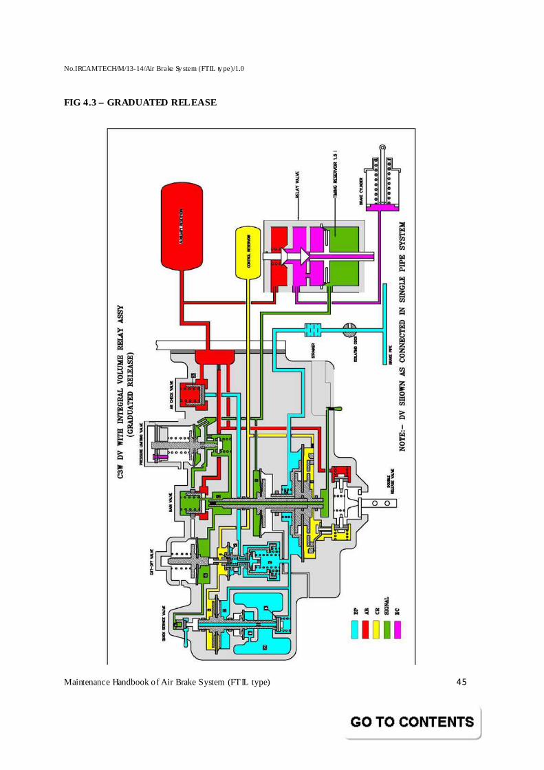
5.3.6.4 GRADUATED RELEASE
When the pressure in Brake Pipe is increased, the balance in the Diaphragm Assembly in the Main Valve is upset due the pressure rise in chamber 2, causing the Piston Assembly to move downwards and thus opening the exhaust passage. Air from Brake Cylinder is released through passage of Hollow Stem and finally is let off to atmosphere through the “Release Choke” located inside Exhaust Protector.
5.3.6.5 OVERCHARGE PROTECTION
Pressure in chamber 11 of the Cut Off Valve under the Seal causes the guide to lift up, making the pin free. The guide will not come down till the Brake Cylinder pressure reaches as low a value as 0.2 bar and till such time the Valve (6) would be kept closed isolating Control Reservoir and eliminating overcharge into Control Reservoir.
5.3.6.6 AUTOMATIC RELEASE
When the Operating Lever is pulled brief ly, the locking rod slides down and gets wedged in between Double Release Valve and its Seat, thereby facilitating draining of Control Reservoir air from chamber 1 and also all the connected chambers. This upsets the balance of the Diaphragm Assembly and opens the exhaust passage. Air pressure from Brake Cylinder and chamber 8 (upper portion of Top Diaphragm) is reduced till a new balance is achieved, thus facilitating a partial brake release. If the Operating Lever is pulled for a long time, the Double Release Valve in the Lower Cover will be moved off from their seats permitting complete draining of the entire system.
No.IRCAMTECH/M/13-14/Air Brake Sy stem (FTIL ty pe)/1.0
Maintenance Handbook o f Air Brake System (FTIL type) 43
FIG 4.1 – CHARGING AND NO RMAL RUNNING CO NDITIO N
No.IRCAMTECH/M/13-14/Air Brake Sy stem (FTIL ty pe)/1.0
Maintenance Handbook o f Air Brake System (FTIL type) 44
FIG 4.2 – GRADUATED APPLICATIO N
No.IRCAMTECH/M/13-14/Air Brake Sy stem (FTIL ty pe)/1.0
Maintenance Handbook o f Air Brake System (FTIL type) 45
FIG 4.3 – GRADUATED RELEASE
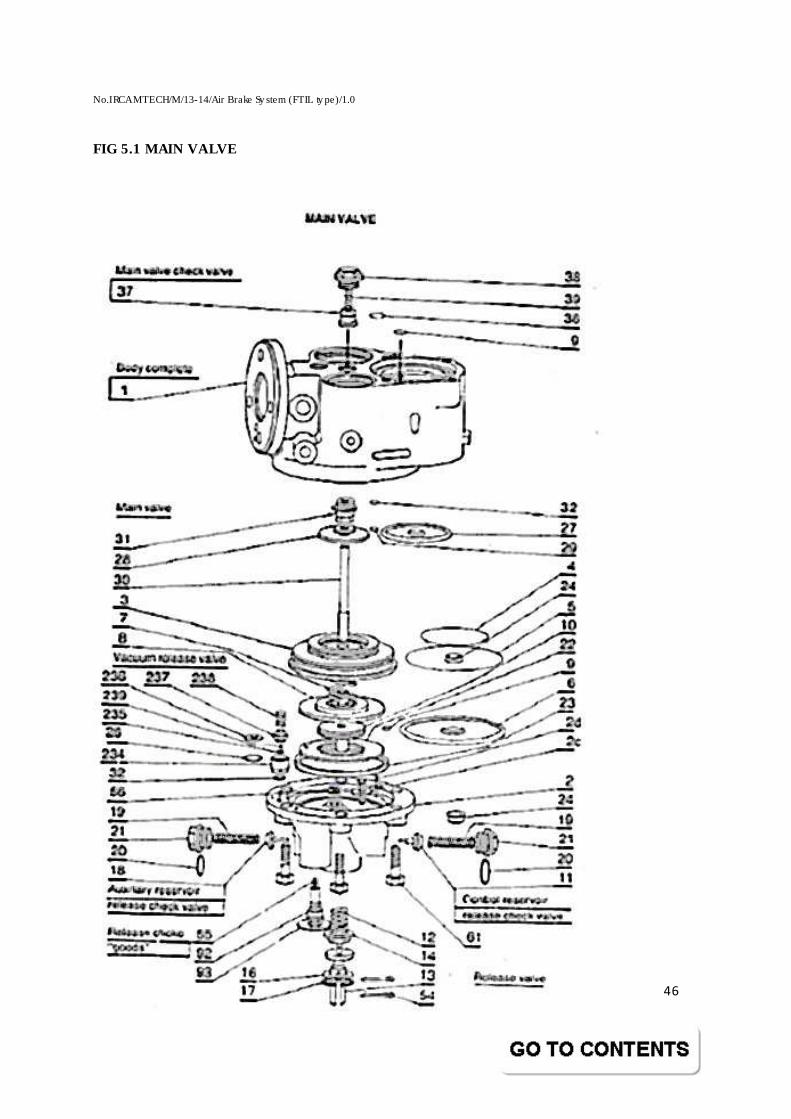
No.IRCAMTECH/M/13-14/Air Brake Sy stem (FTIL ty pe)/1.0
Maintenance Handbook o f Air Brake System (FTIL type) 46
FIG 5.1 MAIN VALVE
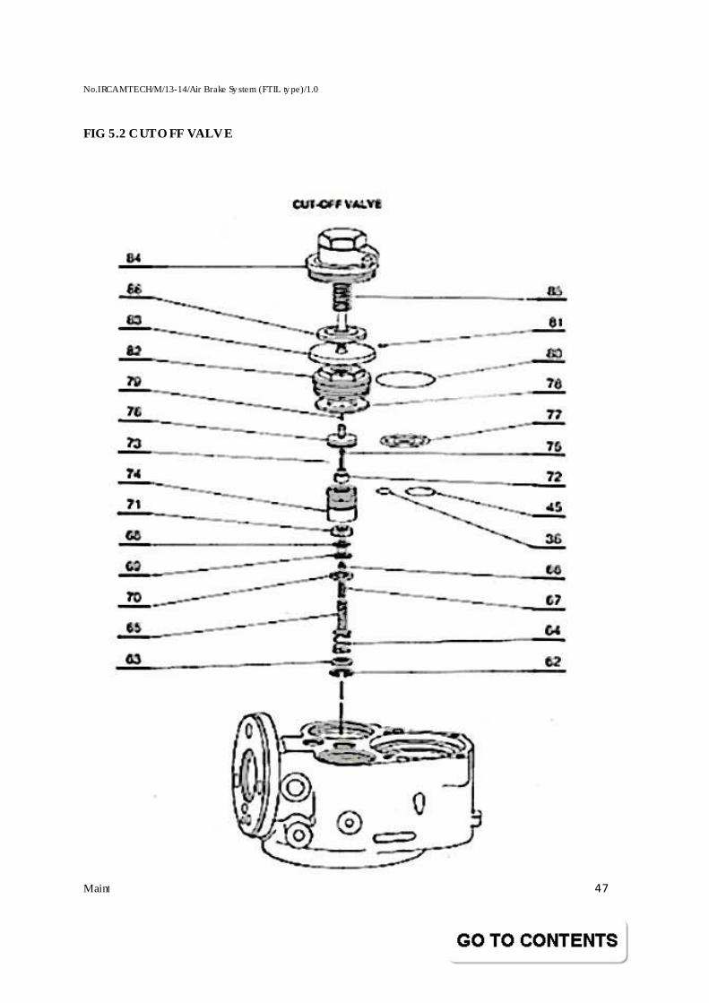
No.IRCAMTECH/M/13-14/Air Brake Sy stem (FTIL ty pe)/1.0
Maintenance Handbook o f Air Brake System (FTIL type) 47
FIG 5.2 CUT O FF VALVE
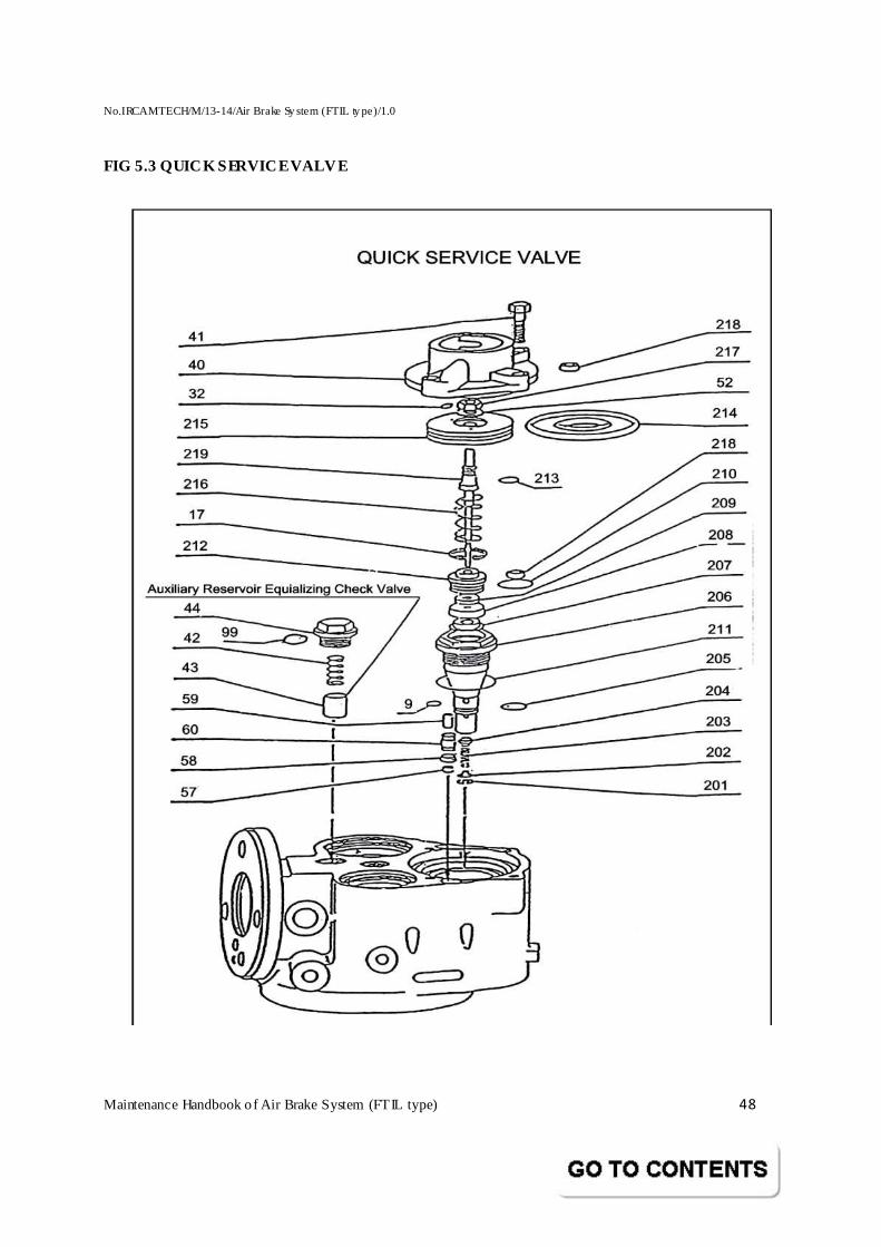
No.IRCAMTECH/M/13-14/Air Brake Sy stem (FTIL ty pe)/1.0
Maintenance Handbook o f Air Brake System (FTIL type) 48
FIG 5.3 QUICK SERVICE VALVE
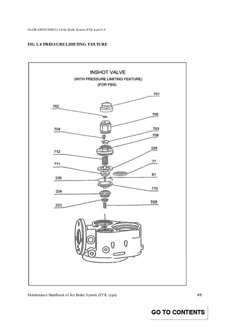
No.IRCAMTECH/M/13-14/Air Brake Sy stem (FTIL ty pe)/1.0
Maintenance Handbook o f Air Brake System (FTIL type) 49
FIG 5.4 PRESSURE LIMITING FEATURE
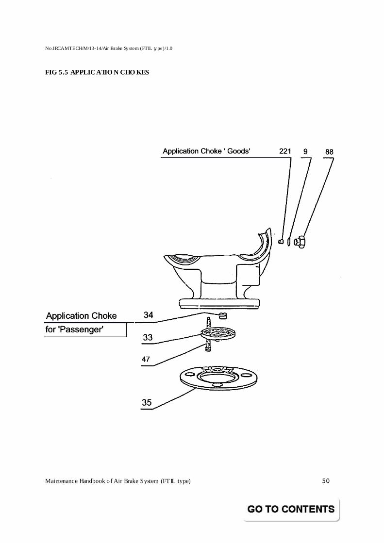
No.IRCAMTECH/M/13-14/Air Brake Sy stem (FTIL ty pe)/1.0
Maintenance Handbook o f Air Brake System (FTIL type) 50
FIG 5.5 APPLICATIO N CHO KES
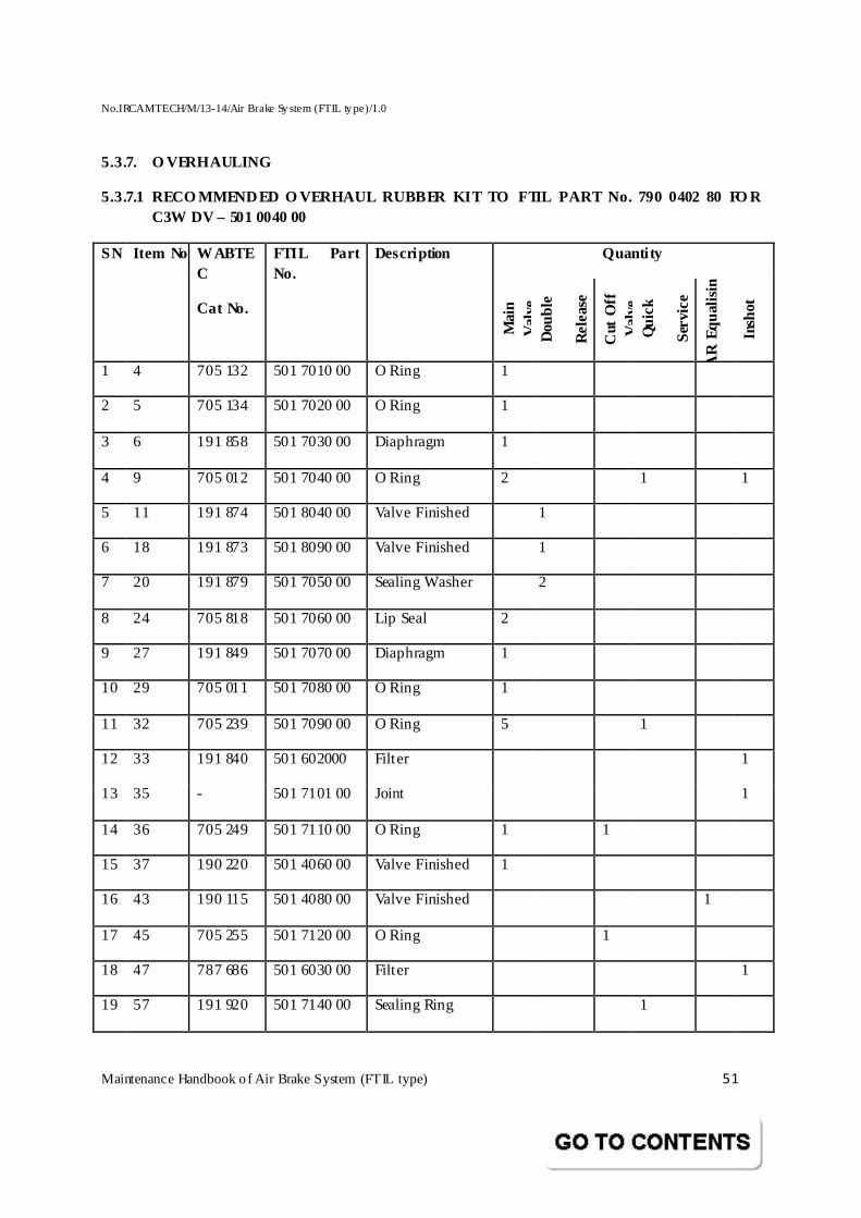
No.IRCAMTECH/M/13-14/Air Brake Sy stem (FTIL ty pe)/1.0
Maintenance Handbook o f Air Brake System (FTIL type) 51
5.3.7. O VERHAULING
5.3.7.1 RECO MMENDED O VERHAUL RUBBER KIT TO FTIL PAR T No. 790 0402 80 FO R C3W DV – 501 0040 00
Quanti ty SN
Item No
WABTEC
Cat No.
FTIL Part No.
Description
Mai
n V
alve
D
oubl
e
Re
leas
e
Cut
Off
V
alve
Q
uick
Ser
vice
AR
Equ
alis
ing
Insh
ot
1 4 705 132 501 7010 00 O Ring 1
2 5 705 134 501 7020 00 O Ring 1
3 6 191 858 501 7030 00 Diaphragm 1
4 9 705 012 501 7040 00 O Ring 2 1 1
5 11 191 874 501 8040 00 Valve Finished 1
6 18 191 873 501 8090 00 Valve Finished 1
7 20 191 879 501 7050 00 Sealing Washer 2
8 24 705 818 501 7060 00 Lip Seal 2
9 27 191 849 501 7070 00 Diaphragm 1
10 29 705 011 501 7080 00 O Ring 1
11 32 705 239 501 7090 00 O Ring 5 1
12 33 191 840 501 602000 Filter 1
13 35 - 501 7101 00 Joint 1
14 36 705 249 501 7110 00 O Ring 1 1
15 37 190 220 501 4060 00 Valve Finished 1
16 43 190 115 501 4080 00 Valve Finished 1
17 45 705 255 501 7120 00 O Ring 1
18 47 787 686 501 6030 00 Filter 1
19 57 191 920 501 7140 00 Sealing Ring 1
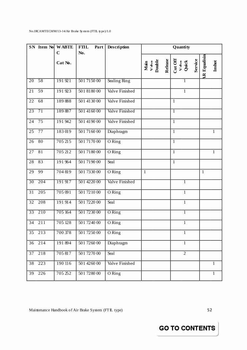
No.IRCAMTECH/M/13-14/Air Brake Sy stem (FTIL ty pe)/1.0
Maintenance Handbook o f Air Brake System (FTIL type) 52
Quanti ty SN
Item No
WABTEC
Cat No.
FTIL Part No.
Description
Mai
n V
alve
D
oubl
e
Re
leas
e
Cut
Off
V
alve
Q
uick
Se
rvic
e
AR
Equ
alis
ing
Insh
ot
20 58 191 921 501 7150 00 Sealing Ring 1
21 59 191 923 501 8180 00 Valve Finished 1
22 68 189 888 501 4130 00 Valve Finished 1
23 71 189 887 501 4160 00 Valve Finished 1
24 75 191 942 501 4190 00 Valve Finished 1
25 77 183 019 501 7160 00 Diaphragm 1 1
26 80 705 215 501 7170 00 O Ring 1
27 81 705 212 501 7180 00 O Ring 1 1
28 83 191 964 501 7190 00 Seal 1
29 99 704 819 501 7330 00 O Ring 1 1
30 204 191 917 501 4220 00 Valve Finished 1
31 205 705 091 501 7210 00 O Ring 1
32 208 191 914 501 7220 00 Seal 1
33 210 705 164 501 7230 00 O Ring 1
34 211 705 128 501 7240 00 O Ring 1
35 213 700 378 501 7250 00 O Ring 1
36 214 191 894 501 7260 00 Diaphragm 1
37 218 705 817 501 7270 00 Seal 2
38 223 190 116 501 4260 00 Valve Finished 1
39 226 705 252 501 7280 00 O Ring 1
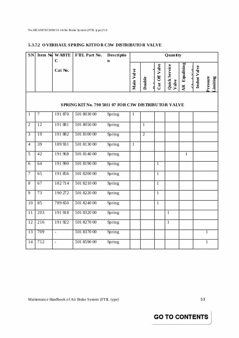
No.IRCAMTECH/M/13-14/Air Brake Sy stem (FTIL ty pe)/1.0
Maintenance Handbook o f Air Brake System (FTIL type) 53
5.3.7.2 O VERHAUL SPRING KIT FO R C3W DISTRIBUTO R VAL VE
Quanti ty SN
Item No
WABTEC
Cat No.
FTIL Part No. Description
Mai
n V
alve
Dou
ble
Re
leas
e v
alve
Cut
Off
Val
ve
Qui
ck S
erv
ice
V
alve
AR
E
qual
isin
g
Che
ck V
alve
In
shot
Val
ve
Pre
ssur
e
Lim
iting
SPRING KIT No. 790 5011 07 FOR C3W DISTRIBUTOR VALVE
1 7 191 870 501 8030 00 Spring 1
2 12 191 881 501 8050 00 Spring 1
3 19 191 882 501 8100 00 Spring 2
4 39 189 931 501 8130 00 Spring 1
5 42 191 968 501 8140 00 Spring 1
6 64 191 990 501 8190 00 Spring 1
7 65 191 856 501 8200 00 Spring 1
8 67 182 714 501 8210 00 Spring 1
9 73 190 272 501 8220 00 Spring 1
10 85 789 650 501 8240 00 Spring 1
11 203 191 918 501 8320 00 Spring 1
12 216 191 922 501 8270 00 Spring 1
13 709 - 501 8370 00 Spring 1
14 712 - 501 8590 00 Spring 1
No.IRCAMTECH/M/13-14/Air Brake Sy stem (FTIL ty pe)/1.0
Maintenance Handbook o f Air Brake System (FTIL type) 54
5.3.7.3 DISMANTLING FROM COACH
Before dismantling the distributor from the coach for overhauling, ensure that the compressed air in the system is drained completely by pulling the operating lever and holding it in position till all the air pressure is fully exhausted.
NOTE:
Since the draining of air supply from the vehicle would release the brakes fully , care should be taken to protect the vehicle and prevent its accidental movement by suitable means.
Remove the DV along with its sandwich piece, relay valve & Timing reservoir.
Carefully supporting the Distributor Valve, unscrew the three M16 Nuts fixing the DV to its sandwich piece.
For further work on the Distributor Valve in the workshop, it is recommended to have a bench mounted clamp bracket with three Studs of M 16 threads, fixed in the same fashion. M ake sure that the fixture has a corresponding hole to accomodate the pin driven in the flange face of the DV. It should also have a facility to rotate by 180° and be locked in either position. (Refer fig. 7). The pipe connections to and from the mounting bracket on the vehicle need not be disturbed. However, it should be protected by a suitable covering to prevent ingress of dirt and dust till the Distributor Valve is reinstalled.
NOTE
Before the DV is opened, it should be thoroughly dusted and cleaned externally. The workbench on which the components are to be placed should also be cleaned thoroughly.
5.3.7.4 DISMANTLING THE DISTRIBUTOR VALVE
� M ount the Distributor Valve on to the Fixture (Fig 7) with the bottom side up.
� Follow the sequence of this operation as given below for dismantling. � The item numbers in this description are with reference to the pull-out diagrams
provided under the relevant heading. � It is imperative that as and when the components are removed from the assembly,
they have to be carefully handled and arranged, preferably in identifiable group sequence.
5.3.7.4.1 MAIN VALVE
(Ref fig. 5.1)
Unscrew the 6 Nos. of Screws (61) & carefully pull upwards the Lower Cover Assembly (2). Take out the Ring (23), the Diaphragm Follower (22) and the Small Piston of Lower Diaphragm (10) along with its Diaphragm (6), the Large Piston of Lower Diaphragm (8), and the five ‘O’ Rings (32).
No.IRCAMTECH/M/13-14/Air Brake Sy stem (FTIL ty pe)/1.0
Maintenance Handbook o f Air Brake System (FTIL type) 55
Press a jet of compressed air into the bore of the Hollow Stem (30) taking care to hold the Hollow Stem (30) the moment it ejects out under pressure. After removing the hollow stem (30), unscrew the release choke from the top opening of the hollow stem.
Remove the Diaphragm Holder (3) and pull out the Hollow Stem from Diaphragm Holder.
Take out the Diaphragm Clamp (28) with its Diaphragm (27).
Unscrew the Plug (31) using the appropriate socket wrench.
Turn the Distributor Valve by 180° on the bracket and ensure that it is again locked in the new position (bottom side down).
Unscrew the Cap (38) [with O’ Ring (99) provided in the latest version] and take out the Spring (39) and Check Valve (37) with the ‘O’ Ring (36).
Carefully remove the Diaphragm (6) from the small Piston of Lower Diaphragm (10) and Diaphragm (27) from the Diaphragm Clamp (28). Also remove the O Rings (4) and (5) from the Diaphragm Holder (3). Similarly remove the ‘O’ Ring (36) from the Check Valve (37).
Using a blunt tool, remove the two Lip Seals (24) from the Diaphragm Holder (3) and from the Lower Cover (2). Similarly, remove the ‘O’ Ring (9), ‘O’ Ring (29) and the ‘O’ Ring (32) from the small Piston of Lower Diaphragm (10), Diaphragm Clamp (28) and the Plug (31) respectively.
NOTE:
Care should be taken not to scratch the rubber components while removing. In case any such damage is suspected, replace such part by a new one.
5.3.7.4.2 DOUBLE RELEASE VALVE
(Ref fig. 5.1)
The Locking Rod (233) would have already come out when the Lower Cover (2) is pulled out. If not, remove it from the hole.
NOTE:
Do not try to remove the grooved Pin (2D) and Trigger (2C). These are permanently fixed in our factory and do not require any attention. While the cover is open, take care to see that no heavy object falls on the pin or on the Trigger.
Keep the flange face down on a soft surface like a rubber pad and press the Operating Lever (13) hard by hand and using the appropriate circlip plier, remove the Circlip (17). Remove the Lower Seat (16) and take over the Operating Lever. Take out the Spring Seats and Valve Operator (14) and the Spring (12).
No.IRCAMTECH/M/13-14/Air Brake Sy stem (FTIL ty pe)/1.0
Maintenance Handbook o f Air Brake System (FTIL type) 56
Slowly unscrew the two Cap Screws (21) on either side and take out the two Springs (19). Take out the Sealing Rings (20) and pull out the Valves (11) and (18).
NOTE
Observe carefully the sides in which these Valves (11) and (18) are to be fixed while assembly.
Unscrew the Exhaust Protector (92) carefully and unscrew the Release Choke (55) from the Exhaust Protector (92) and take out the Exhaust Ring Protector (93).
5.3.7.4.3 CUT-OFF VALVE
(Ref fig. 5.2)
With the Distributor Valve mounted in its normal position, proceed as follows:
� Unscrew the bigger Cap (84) by using the appropriate socket wrench. Alternatively, a rod of suitable diameter that can go into the side hole on the cap can also be used.
� Carefully lift off the Cap (84) and remove the Spring (85), the Guide (86) and the Seal (83). If the Seal does not come out alone with the Guide and remain in stuck in position, use a bent tool and carefully lift it up. Rotating the tool all around, lift the seal uniformly and gradually from underneath. Ensure that the tool has no sharp edges.
NOTE
Ensure after removing the Seal that the two Springs in the Seal are properly seated in their position. The ends of the Springs are inserted into one another to form a ring of a specified diameter. Improper handling of the seal while pulling out may disturb the position of the Springs.
Remove the ‘O’ rings (81) from the Guide (86) taking proper care.
Unscrew the Diaphragm Clamping Screw (82) using the appropriate socket wrench. Take out the Push Rod (79).
NOTE
The direction in which the push rod has to be inserted again during reassembly should be carefully noted down.
Holding the stem part of Guide (76), pull it out carefully so that the Diaphragm Clamp (78) also comes out. The Guide (76) is a sub-assy consisting of Seat (72) which is screwed into the Guide (76) Valve (75), Spring (73) & the Diaphragm (77).
Keep the sub-assembly in the special Fixture RPBF 0003 (Fig 6.3) in such a way that the flange part of the Guide (76) sits in the circular recess of the fixture and the Seat (72) is facing up. Keep the Fixture in a vice. Tighten the vice lightly. Using the special tool
No.IRCAMTECH/M/13-14/Air Brake Sy stem (FTIL ty pe)/1.0
Maintenance Handbook o f Air Brake System (FTIL type) 57
SCT6016 (Fig 6.3) unscrew the Seat (72) by inserting the two Pins of the tool into the two holes on the Seat (72) and turning the handle.
Take out Valve (75) and the Spring (73).
NOTE
While using the fixture RPBF 0003 (Fig 6.3), exercise care to avoid denting the flange of the Guide (76) due to over tightening of the vice. The Spring (73) and the Valve (75) are quite small in size and should be handled carefully.
Pull out Diaphragm (77).
Using special tool SCT 6014 (Fig 6.1) in the same way as for SCT 6016 (Fig 6.3), unscrew the Plug (74) and remove the outer ‘O’ Ring (45) as well as the inner ‘O’ Ring (36). The Plug is a sub-assembly consisting of an Internal Circlip (62), Spring Seats (63), (69) and (70), Spring (64) (65) and (67), a Solex Jet (66) and Valve Finished (68) and (71). Using a suitable circlip plier, remove the Circlip (62). Take out the Spring Seat (63) exercising caution in avoiding falling of loose components. Take out the Springs (64) (65) and (67). By pulling at Solex Jet (66), remove the Spring Seats (69) and (70).
Take out the Valve Finished (68) and (71). Unscrew the Solex Jet from the Valve (68).
5.3.7.4.4 QUICK SERVICE VALVE
(Ref fig. 5.3)
With Clamp bracket in the same position as for Cut Off Valve, unscrew the four Screws (41).
Take the Cover Assembly (40) out, taking care to pull it up vertically.
Remove the ‘O’ Ring (32) and ‘O’ Ring (9) on the top surface of the Body.
Slowly pull out the Glide Plunger (219) sub-assembly consisting of parts (52), (213), (214), (215), (217) and (219) by pulling at the Guide Plunger top.
Remove the Spring (216).
Remove the Diaphragm (214) from the Piston (215) of the sub-assembly.
Holding the sub-assembly in hand, unscrew the Nut (217), remove the Washer (52) and pull out the Piston (215).
Remove the “O” Ring (213) without twisting it. Using the special tool SCT 6092 (Fig. 6.1) unscrew the Seat Holder (206).
Remove the “O” Rings (211) and (205).
Take out the Seat Holder Assembly (206) and using the appropriate circlip plier, remove the Internal Circlip (17). Pull out the Seal Holder (212) using the special tool SCT 6093 (Fig 6.2). Remove the “O” Ring (210)
Using a blunt tool, carefully pull out the seal (218) from the Seal Holder (212).
No.IRCAMTECH/M/13-14/Air Brake Sy stem (FTIL ty pe)/1.0
Maintenance Handbook o f Air Brake System (FTIL type) 58
Remove the Washer (209). Carefully pull out the Seal (208) by using a bent tool and dragging up uniformly all round. Do not use any sharp hook to do this work.
Take out the Spring Seat (207).
Using the appropriate internal circlip plier, extract the Circlip (201) at the bottom of Seat Holder (206), taking care to prevent loose parts from inside falling off.
Remove the Spring Seat (202), Spring (203) and Valve Finished (204).
Using the same tool as was used for pulling out the Seal (218) from the Seal Holder (212), pull out the second Seal (218) from the Cover Assembly (40).
Take out the Bush (60) carefully by pressing a jet of compressed against the vent of quick service and the Valve Finished (59) from the hole in the top face of Body (1).
Extract the Seal (58) and the Sealing Ring (57) by carefully pressing on the Seal (58) on an edge to tilt it on Washer (57). Use only a blunt tool.
NOTE
While extracting the Seal (58) be careful not to damage it. However, as this cannot be pulled out in any other way than described above, if any damage to this component is suspected, make sure to replace it by a new one during reassembly.
5.3.7.4.5 AUXILIARY RESERVOIR VALVE
(Refer fig. 5.3)
With Body (1) in the normal position, unscrew the Cap (44) & O Ring (provided in latest version) slowly & take out the Check Valve Spring (42) & Check Valve (43).
5.3.7.4.6 PRESSURE LIMITING FEATURE
(Ref. fig 5.4)
Open the Cap (701) remove Circlip (702), Stem Adjusting Screw (704) using special tool (Fig 12 A) and remove Spring Seat (703) from Clamping Flange (708).
Unscrew Clamping Flange and remove Spring (712) extract Diaphragm Clamp (228) and pull out Guide (711). Remove Diaphragm (77) from Guide (711). Remove O Ring (226) from its seating position on Cup (710) and remove the cup. Unscrew Plug (224) and remove Valve Finished (223) and extract the Spring (709).
No.IRCAMTECH/M/13-14/Air Brake Sy stem (FTIL ty pe)/1.0
Maintenance Handbook o f Air Brake System (FTIL type) 59
5.3.7.4.7 APPLICATION AND RELEASE CHOKES
(Ref fig. 5.5)
APPLICATION CHOKE
Remove from the side of Body the Application Choke (34) provided inside the Filter (32). The Filter has to be removed for renewal or cleaning of Choke.
RELEASE CHOKE
The Release Choke is provided in the hollow stem(30).
Choke description FTIL PART NO
Application Passenger 501 4309 00
Release Passenger 011 3062 00
5.3.7.5 CLEANING OF PARTS
Refer guidelines given under "CLEANING PROCEDURE (AIR BRAKE EQUIPM ENTS / COMPONENTS)"
REPLACE PARTS IF,
Refer the guidelines given under "INSPECTION / REPLACEMENT CRITERIA (AIR
BRAKE EQUIPM ENT / COMPONENTS)"
STEPS BEFORE REASSEMBLY
Smear carefully and lightly “M OLYKOTE M 33” or equivalent grease to all
� Slid ing parts � Dynamic and static O rings and the parts on to which they slide. � Diaphragms and seals � Threaded parts except on the chokes and the Solex jet.
Smear carefully and lightly “ Shell Rhodina RL3” grease or equivalent to all
� Threaded parts of chokes and Solex jet � Bearings of all guides
No.IRCAMTECH/M/13-14/Air Brake Sy stem (FTIL ty pe)/1.0
Maintenance Handbook o f Air Brake System (FTIL type) 60
5.3.7.6 ASSEMBLY
Follow the same instructions of each sub-assembly in the reverse sequence to assemble the valves. However, suggestions given as under while reassembly may be followed.
After mounting the Diaphragms on the Diaphragm Clamps, get the entrapped air out by inserting the special tool SCT 6026 (Fig 6.3) between the inside the Lip and the side of the Groove.
The elastomer surfaces of the valve must be free from grease.
Blow a jet of compressed on to the valve surfaces before assembling them into position.
Ensure that the tips of the screwdrivers, the circlip pliers and the other tools used are free from any sticky matter and are not carry ing any dirt.
The ‘O’ Ring (226) in the Inshot Valve Cup (225) is not mounted outside but is dropped into position after fixing the cup in its p lace with the help of a special tool SCT 6015 (Fig 6.1) suitably pushed uniformly into position. Keep the edge of the tool on the ‘O’ Ring & rotate the tool with light pressure till ‘O’ ring is seated properly without twist.
After assembling the parts (62) – (71) of the Cut Off Valve into the Plug (74), shake it lightly; a metallic sound should be heard. If not, extract the Circlip (62), remove the Spring Seat (63) and make sure that the Springs are correctly positioned. Also ensure a Spring Seats (69) and (70) are freely moving. Then reassemble the parts and repeat the operation.
To insert the Hollow Stem (30) through the Diaphragm Clamp (28), use the special feeding tool SCT 6017 (Fig 6.3) to avoid scratching of the ‘O’ Ring (29) in the Diaphragm Clamp (28). This is done by the inserting tool into the Hollow Stem (30) on the side of the small diameter and pushing the tapered face of the tool into the Diaphragm Clamp slowly. Pull out the tool from the stem on the other side.
For the Inshot Valve portion, the Pressure Limiting arrangement consisting of items 701, 702, 703, 704 & 705 are also required to be assembled in the Inshot Valve portion.
NOTE
The limiting pressure is to be adjusted for a cut off pressure of 3.8 Kg/Cm2 during DV test.
5.3.7.7 TIGHTENING TORQUE
TIGHTEN TO A TORQUE OF 20 – 25 Nm,
The Plug (74) and Seat (72) of the Cut Off Valve.
The Nut (217) of the Quick Service Valve Guide Plunger and Seat Holder (206) of the Quick Service Valve sub-assembly.
No.IRCAMTECH/M/13-14/Air Brake Sy stem (FTIL ty pe)/1.0
Maintenance Handbook o f Air Brake System (FTIL type) 61
The Plug (31) in the M ain Valve.
The Valve Seat (224) in the Inshot Valve and
The Caps (21) of the Double Release Valve.
After assembling the Double Release Valve in the Lower Cover (2), pull the Operating Lever (13) to the side in which the Trigger is pinned and press the Locking Rod (233) down, so that it gets jammed between the Valve Seat and the Valve (11). Then even if the Operating Lever is released, the entire Lower Cover Sub-assembly (2) can be turned upside down to be mounted on Body (1) without the Locking Rod falling down. This Locking Rod gets released automatically once the DV is charged with air pressure to the
required limits.
5.3.8 TESTING OF C3W DISTRIBUTOR VALVE AFTER OVERHA UL
After the Distributor Valve is overhauled thoroughly and assembled as described, fix the DV on the sandwich piece & attach the relay valve & timing volume as a unit assembly. Then it is to be mounted on to BRAKE PANEL MODULE (A0). Compressed air is to be charged at the specified pressure and Distributor Valve should be operated a few times, say 20 operations to execute a few applications and release cycles. Do not check for the leak tightness of the Distributor Valve during this cyclic operation.
After cycling, charge the Distributor Valve to 5.0 Kg/cm2 in a single pipe system and wait till the Auxiliary Reservoir and Control Reservoir also attain 5.0 Kg/cm2 .
At this stage, soap solution can be used to detect leak bubbles. If any leaks are observed, proper remedial action should be taken as per troubleshooting guide (attached) and Distributor Valve is to be rechecked for leak tightness and the performance. It is not required to check for leaks for duration of 5 minutes each. It is enough if a leak did not appear in one minute and even if it starts surfacing after a period of one minute, it can be considered as negligib ly small and hence can be ignored.
NOTE :-
1. Distributor Valve (501 0040 00) alone cannot be tested as it is working along with the relay valve assembly (018 0040 00).
2. However the trouble shooting can be followed independently as provided under distributor valve & Relay valve.
5.3.8.1 FREQUENCY OF OVERHAULING
The Valve once put into field service needs no attention as long as the operating conditions and maintenance practices are as under are fo llowed till its periodic overhaul.
“Reliable performance of C3W Distributor Valve is assured provided basic cleanliness inside the pipelines, reservoirs and at hose pipe ends is maintained and proper attention is given to air tightness, draining of reservoirs, filters, prevention of dust/dirt/moisture ingress.”
No.IRCAMTECH/M/13-14/Air Brake Sy stem (FTIL ty pe)/1.0
Maintenance Handbook o f Air Brake System (FTIL type) 62
However, observation on Distributor Valves during Sick Line / workshop attention generally indicate substantial presence of some of the factors like moisture, dirt, water / oily sludge, corrosion rust, scales, etc, on the inside of BP/FP pipelines and brake system equipments. These are collected / formed over a period primarily due to non-supply of dry air / other operational reasons & may affect the performance parameters during operation. As such in order to ensure a sustained reliable performance, it is recommended to remove the Distributor Valve once in three years after the date of commissioning and coinciding the nearest POH towards performance test/examination and overhaul at a centralized workshop. In practice, it is enough to pay attention to the DV for any performance deviations noticed when the vehicle is serviced during the test in POH.
5.3.8.2 TROUBLE- SHOOTING
Some of the distress symptoms / failures are given below for guidance duly indicating the possible sources of causes and contributory factors. The sequence of these failures and the possible sources are arranged in their decreasing order of probability of occurrence. However, while analyzing any such failure in the suggested sequential priority, the check need not be stopped at any particular cause of failure but better be continued to cover the other remaining causes that could also contribute to the same observation.
No.IRCAMTECH/M/13-14/Air Brake Sy stem (FTIL ty pe)/1.0
Maintenance Handbook o f Air Brake System (FTIL type) 63
5.3.8.2.1 CONTROL RESERVOIR ALONE AT 5.0 Kg/cm2
Operation Failure
Observations Causes of failure Remedial Action
Leak at Exhaust Ring Protector (93).
In the M ain Valve Lip Seal (24) in the Lower Cover (2) is defective or fixed upside down.
Replace the Lip Seal (24) or assemble correctly.
Leak at Quick Release Chamber Outlet (F)
Lip Seal (218) in the Cover (40) of Quick Service Bulb defective or fixed upside down.
Replace or assemble correctly.
Surface condition of Valve (75) in the Cut-off valve defective.
Replace the valve
Spring (73) wrapped. Replace.
Diaphragm (6 & 214) or Diaphragm (77) defective or wrongly assembled.
Replace or relocate
Leak back to the Brake Pipe, when the Brake Pipe pressure is reduced.
‘O’ Ring (213) defective or twisted between 215 & 219.
d. Replace or relocate.
Leak at the Release Valve Lever (L)
Surface condition of Valve (11) defective in Double Release Valve (the one on the opposite side of the flange)
Replace the valve and attend.
Wrongly assembled diaphragm (6)
Relocate the diaphragm. Leak to atmosphere at the Hole (s) in the bottom cover, under Brake Cylinder
reaction pressure. ‘O’ Ring (32) between body (1) and lower cover (2) defective
Replace ‘O’ Ring
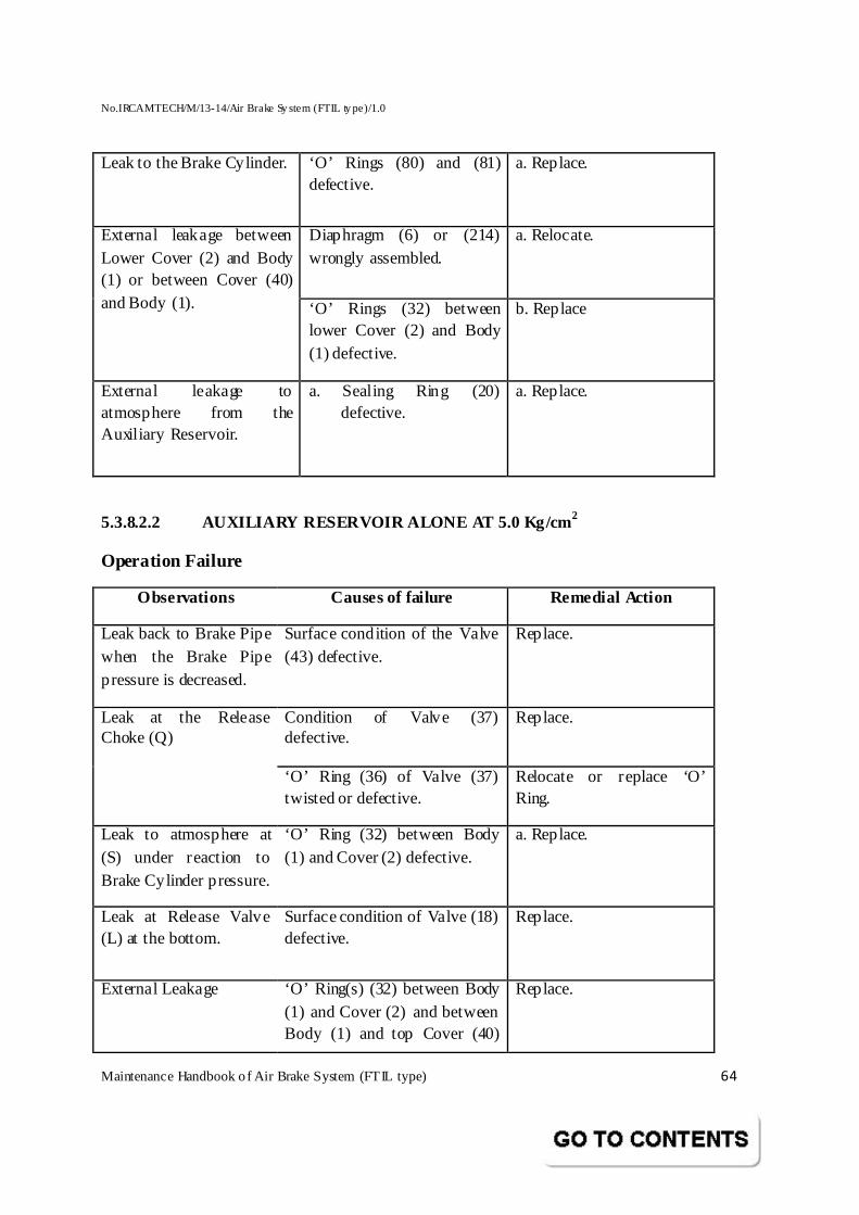
No.IRCAMTECH/M/13-14/Air Brake Sy stem (FTIL ty pe)/1.0
Maintenance Handbook o f Air Brake System (FTIL type) 64
Leak to the Brake Cylinder. ‘O’ Rings (80) and (81) defective.
a. Replace.
Diaphragm (6) or (214) wrongly assembled.
a. Relocate.
External leakage between Lower Cover (2) and Body (1) or between Cover (40) and Body (1).
‘O’ Rings (32) between lower Cover (2) and Body (1) defective.
b. Replace
External leakage to atmosphere from the Auxiliary Reservoir.
a. Sealing Ring (20) defective.
a. Replace.
5.3.8.2.2 AUXILIARY RESERVOIR ALONE AT 5.0 Kg/cm 2
Operation Failure
Observations Causes of failure Remedial Action
Leak back to Brake Pipe when the Brake Pipe pressure is decreased.
Surface condition of the Valve (43) defective.
Replace.
Condition of Valve (37) defective.
Replace. Leak at the Release Choke (Q)
‘O’ Ring (36) of Valve (37) twisted or defective.
Relocate or replace ‘O’ Ring.
Leak to atmosphere at (S) under reaction to Brake Cylinder pressure.
‘O’ Ring (32) between Body (1) and Cover (2) defective.
a. Replace.
Leak at Release Valve (L) at the bottom.
Surface condition of Valve (18) defective.
Replace.
External Leakage
‘O’ Ring(s) (32) between Body (1) and Cover (2) and between Body (1) and top Cover (40)
Replace.
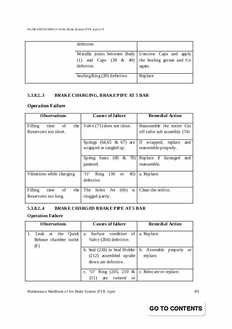
No.IRCAMTECH/M/13-14/Air Brake Sy stem (FTIL ty pe)/1.0
Maintenance Handbook o f Air Brake System (FTIL type) 65
defective.
M etallic joints between Body (1) and Caps (38 & 40) defective.
Unscrew Caps and apply the Sealing grease and f ix again.
Sealing Ring (20) defective. Replace
5.3.8.2..3 BRAKE CHARGING, BRAKE PIPE AT 5 BAR
Operation Failure
Observations Causes of failure Remedial Action
Valve (71) does not close. Reassemble the entire Cut off valve sub assembly (74)
Springs (64,65 & 67) are wrapped or tangled up.
If wrapped, replace and reassemble properly.
Filling time of the Reservoirs too short.
Spring Seats (69 & 70) jammed.
Replace if damaged and reassemble.
Vibrations while charging ‘O’ Ring (36 or 45) defective.
a. Replace.
Filling time of the Reservoirs too long.
The Solex Jet (66) is clogged partly.
Clean the orifice.
5.3.8.2..4 BRAKE CHARGED BRAKE PIPE AT 5 BAR
Operation Failure
Observations Causes of failure Remedial Action
a. Surface condition of Valve (204) defective.
a. Replace.
b. Seal (218) in Seal Holder (212) assembled upside down are defective.
b. Assemble properly or replace.
1. Leak at the Quick Release chamber outlet (F)
c. ‘O’ Ring (205, 210 & 211) are twisted or
c. Relocate or replace.
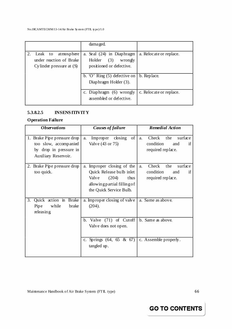
No.IRCAMTECH/M/13-14/Air Brake Sy stem (FTIL ty pe)/1.0
Maintenance Handbook o f Air Brake System (FTIL type) 66
damaged.
a. Seal (24) in Diaphragm Holder (3) wrongly positioned or defective.
a. Relocate or replace.
b. ‘O’ Ring (5) defective on Diaphragm Holder (3).
b. Replace.
2. Leak to atmosphere under reaction of Brake Cylinder pressure at (S)
c. Diaphragm (6) wrongly assembled or defective.
c. Relocate or replace.
5.3.8.2.5 INSENSITIVITY
Operation Failure
Observations Causes of failure Remedial Action
1. Brake Pipe pressure drop too slow, accompanied by drop in pressure in Auxiliary Reservoir.
a. Improper closing of Valve (43 or 75)
a. Check the surface condition and if required replace.
2. Brake Pipe pressure drop too quick.
a. Improper closing of the Quick Release bulb inlet Valve (204) thus allowing partial filling of the Quick Service Bulb.
a. Check the surface condition and if required replace.
a. Improper closing of valve (204).
a. Same as above.
b. Valve (71) of Cutoff Valve does not open.
b. Same as above.
3. Quick action in Brake Pipe while brake releasing.
c. Springs (64, 65 & 67) tangled up.
c. Assemble properly.
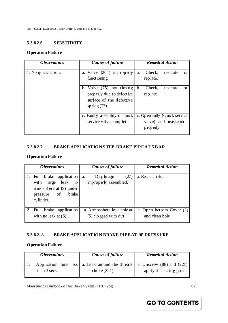
No.IRCAMTECH/M/13-14/Air Brake Sy stem (FTIL ty pe)/1.0
Maintenance Handbook o f Air Brake System (FTIL type) 67
5.3.8.2.6 SENSITIVITY
Operation Failure
Observations Causes of failure Remedial Action
a. Valve (204) improperly functioning.
a. Check, relocate or replace.
b. Valve (75) not closing properly due to defective surface of the defective spring (73)
b. Check, relocate or replace.
1. No quick action.
c. Faulty assembly of quick service valve complete
c. Open fully (Quick service valve) and reassemble properly
5.3.8.2.7 BRAKE APPLICATION STEP, BRAKE PIPE AT 5 BAR
Operation Failure
Observations Causes of failure Remedial Action
1. Full brake application with large leak to atmosphere at (S) under pressure of brake cylinder.
a. Diaphragm (27) improperly assembled.
a. Reassemble.
2. Full brake application with no leak at (S).
a. Atmosphere leak hole at (S) clogged with dirt.
a. Open bottom Cover (2) and clean hole.
5.3.8.2..8 BRAKE APPLICATION BRAKE PIPE AT ‘0’ PRES SURE
Operation Failure
Observations Causes of failure Remedial Action
1. Application time less than 3 secs.
a. Leak around the threads of choke (221)
a. Unscrew (88) and (221) apply the sealing grease
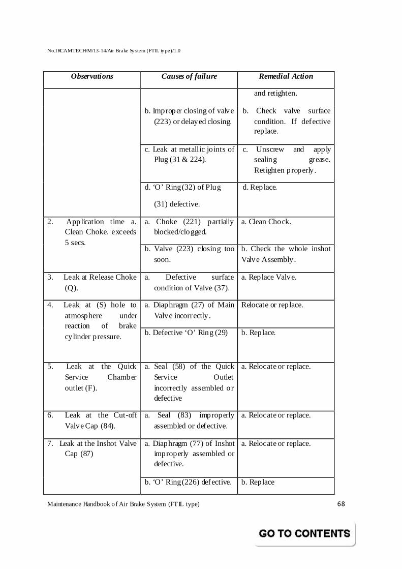
No.IRCAMTECH/M/13-14/Air Brake Sy stem (FTIL ty pe)/1.0
Maintenance Handbook o f Air Brake System (FTIL type) 68
Observations Causes of failure Remedial Action
and retighten.
b. Improper closing of valve (223) or delayed closing.
b. Check valve surface condition. If defective replace.
c. Leak at metallic jo ints of Plug (31 & 224).
c. Unscrew and apply sealing grease. Retighten properly.
d. ‘O’ Ring (32) of Plug
(31) defective.
d. Replace.
a. Choke (221) partially blocked/clogged.
a. Clean Chock. 2. Application time a. Clean Choke. exceeds 5 secs.
b. Valve (223) closing too soon.
b. Check the whole inshot Valve Assembly.
3. Leak at Release Choke (Q).
a. Defective surface condition of Valve (37).
a. Replace Valve.
a. Diaphragm (27) of Main Valve incorrectly.
Relocate or replace. 4. Leak at (S) hole to atmosphere under reaction of brake cylinder pressure. b. Defective ‘O’ Ring (29)
b. Replace.
5. Leak at the Quick Service Chamber outlet (F).
a. Seal (58) of the Quick Service Outlet incorrectly assembled or defective
a. Relocate or replace.
6. Leak at the Cut-off Valve Cap (84).
a. Seal (83) improperly assembled or defective.
a. Relocate or replace.
a. Diaphragm (77) of Inshot improperly assembled or defective.
a. Relocate or replace. 7. Leak at the Inshot Valve Cap (87)
b. ‘O’ Ring (226) defective. b. Replace
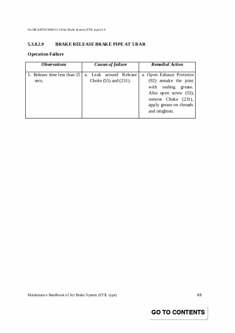
No.IRCAMTECH/M/13-14/Air Brake Sy stem (FTIL ty pe)/1.0
Maintenance Handbook o f Air Brake System (FTIL type) 69
5.3.8.2.9 BRAKE RELEASE BRAKE PIPE AT 5 BAR
Operation Failure
Observations Causes of failure Remedial Action
1. Release time less than 15 secs.
a. Leak around Release Choke (55) and (231).
a. Open Exhaust Protector (92) remake the joint with sealing grease. Also open screw (53), remove Choke (231), apply grease on threads and retighten.
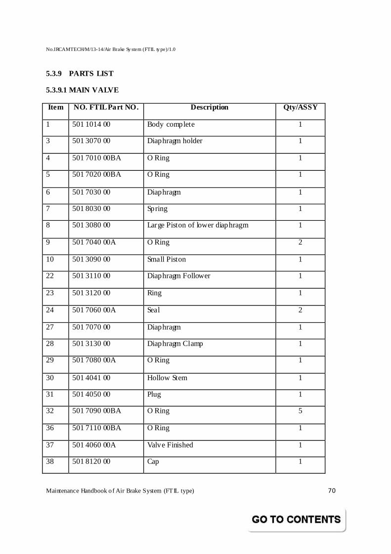
No.IRCAMTECH/M/13-14/Air Brake Sy stem (FTIL ty pe)/1.0
Maintenance Handbook o f Air Brake System (FTIL type) 70
5.3.9 PARTS LIST
5.3.9.1 MAIN VALVE
Item NO. FTIL Part NO. Description Qty/ASSY
1 501 1014 00 Body complete 1
3 501 3070 00 Diaphragm holder 1
4 501 7010 00BA O Ring 1
5 501 7020 00BA O Ring 1
6 501 7030 00 Diaphragm 1
7 501 8030 00 Spring 1
8 501 3080 00 Large Piston of lower diaphragm 1
9 501 7040 00A O Ring 2
10 501 3090 00 Small Piston 1
22 501 3110 00 Diaphragm Follower 1
23 501 3120 00 Ring 1
24 501 7060 00A Seal 2
27 501 7070 00 Diaphragm 1
28 501 3130 00 Diaphragm Clamp 1
29 501 7080 00A O Ring 1
30 501 4041 00 Hollow Stem 1
31 501 4050 00 Plug 1
32 501 7090 00BA O Ring 5
36 501 7110 00BA O Ring 1
37 501 4060 00A Valve Finished 1
38 501 8120 00 Cap 1
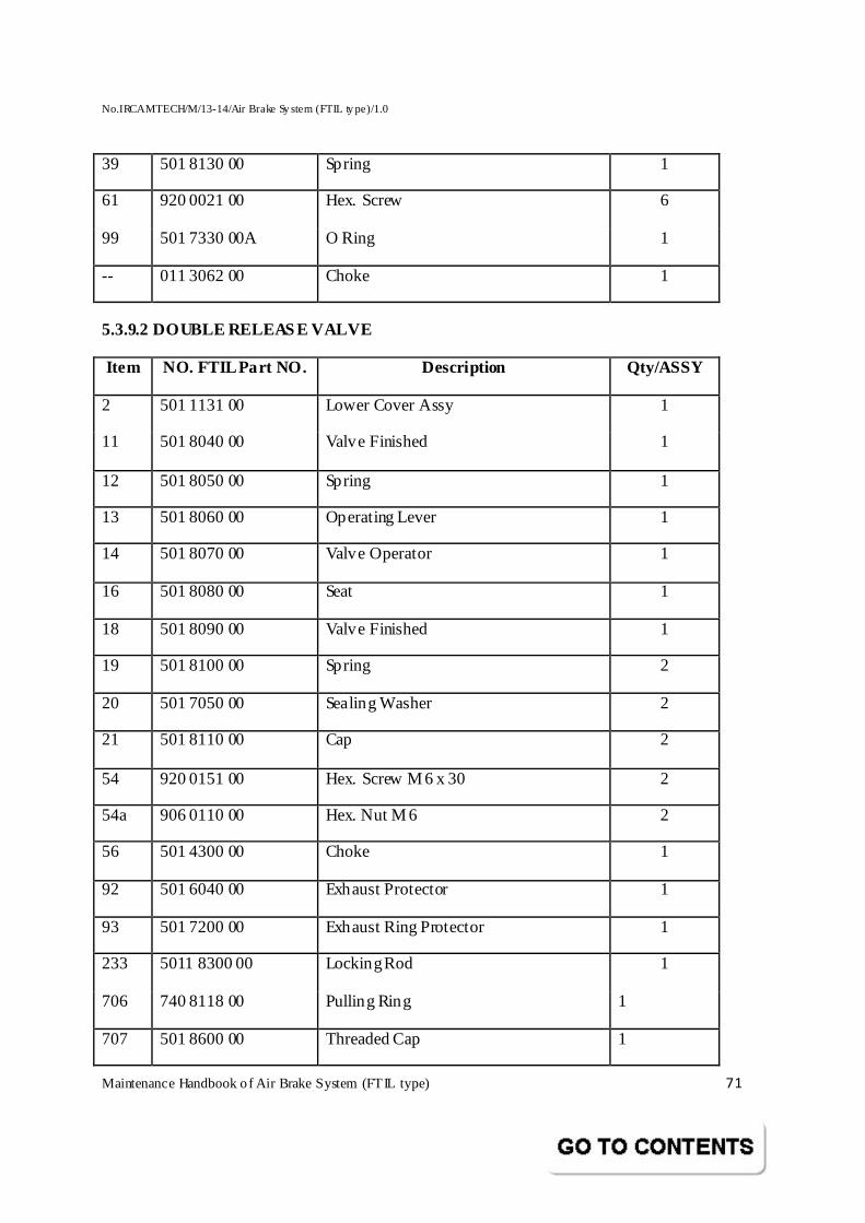
No.IRCAMTECH/M/13-14/Air Brake Sy stem (FTIL ty pe)/1.0
Maintenance Handbook o f Air Brake System (FTIL type) 71
39 501 8130 00 Spring 1
61 920 0021 00 Hex. Screw 6
99 501 7330 00A O Ring 1
-- 011 3062 00 Choke 1
5.3.9.2 DOUBLE RELEASE VALVE
Item NO. FTIL Part NO. Description Qty/ASSY
2 501 1131 00 Lower Cover Assy 1
11 501 8040 00 Valve Finished 1
12 501 8050 00 Spring 1
13 501 8060 00 Operating Lever 1
14 501 8070 00 Valve Operator 1
16 501 8080 00 Seat 1
18 501 8090 00 Valve Finished 1
19 501 8100 00 Spring 2
20 501 7050 00 Sealing Washer 2
21 501 8110 00 Cap 2
54 920 0151 00 Hex. Screw M 6 x 30 2
54a 906 0110 00 Hex. Nut M 6 2
56 501 4300 00 Choke 1
92 501 6040 00 Exhaust Protector 1
93 501 7200 00 Exhaust Ring Protector 1
233 5011 8300 00 Locking Rod 1
706 740 8118 00 Pulling Ring 1
707 501 8600 00 Threaded Cap 1
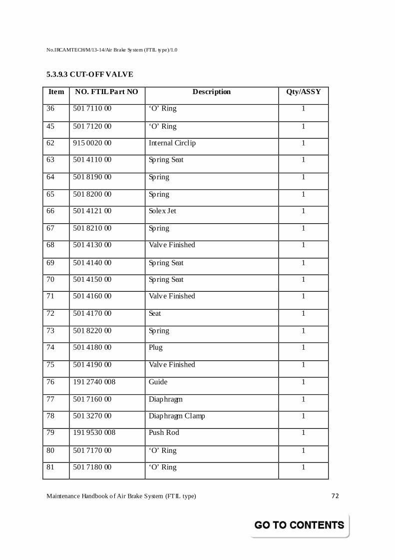
No.IRCAMTECH/M/13-14/Air Brake Sy stem (FTIL ty pe)/1.0
Maintenance Handbook o f Air Brake System (FTIL type) 72
5.3.9.3 CUT-OFF VALVE
Item NO. FTIL Part NO Description Qty/ASSY
36 501 7110 00 ‘O’ Ring 1
45 501 7120 00 ‘O’ Ring 1
62 915 0020 00 Internal Circlip 1
63 501 4110 00 Spring Seat 1
64 501 8190 00 Spring 1
65 501 8200 00 Spring 1
66 501 4121 00 Solex Jet 1
67 501 8210 00 Spring 1
68 501 4130 00 Valve Finished 1
69 501 4140 00 Spring Seat 1
70 501 4150 00 Spring Seat 1
71 501 4160 00 Valve Finished 1
72 501 4170 00 Seat 1
73 501 8220 00 Spring 1
74 501 4180 00 Plug 1
75 501 4190 00 Valve Finished 1
76 191 2740 008 Guide 1
77 501 7160 00 Diaphragm 1
78 501 3270 00 Diaphragm Clamp 1
79 191 9530 008 Push Rod 1
80 501 7170 00 ‘O’ Ring 1
81 501 7180 00 ‘O’ Ring 1
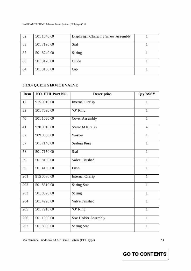
No.IRCAMTECH/M/13-14/Air Brake Sy stem (FTIL ty pe)/1.0
Maintenance Handbook o f Air Brake System (FTIL type) 73
82 501 1040 00 Diaphragm Clamping Screw Assembly 1
83 501 7190 00 Seal 1
85 501 8240 00 Spring 1
86 501 3170 00 Guide 1
84 501 3160 00 Cap 1
5.3.9.4 QUICK SERVICE VALVE
Item NO. FTIL Part NO. Description Qty/ASSY
17 915 0010 00 Internal Circlip 1
32 501 7090 00 ‘O’ Ring 1
40 501 1030 00 Cover Assembly 1
41 920 0010 00 Screw M10 x 35 4
52 909 0050 00 Washer 1
57 501 7140 00 Sealing Ring 1
58 501 7150 00 Seal 1
59 501 8180 00 Valve Finished 1
60 501 4100 00 Bush 1
201 915 0030 00 Internal Circlip 1
202 501 8310 00 Spring Seat 1
203 501 8320 00 Spring 1
204 501 4220 00 Valve Finished 1
205 501 7210 00 ‘O’ Ring 1
206 501 1050 00 Seat Holder Assembly 1
207 501 8330 00 Spring Seat 1
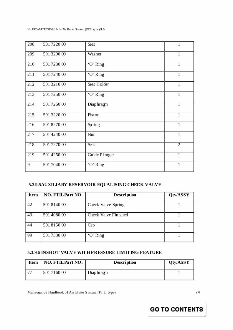
No.IRCAMTECH/M/13-14/Air Brake Sy stem (FTIL ty pe)/1.0
Maintenance Handbook o f Air Brake System (FTIL type) 74
208 501 7220 00 Seat 1
209 501 3200 00 Washer 1
210 501 7230 00 ‘O’ Ring 1
211 501 7240 00 ‘O’ Ring 1
212 501 3210 00 Seat Holder 1
213 501 7250 00 ‘O’ Ring 1
214 501 7260 00 Diaphragm 1
215 501 3220 00 Piston 1
216 501 8270 00 Spring 1
217 501 4240 00 Nut 1
218 501 7270 00 Seat 2
219 501 4250 00 Guide Plunger 1
9 501 7040 00 ‘O’ Ring 1
5.3.9.5AUXILIARY RESERVOIR EQUALISING CHECK VALVE
Item NO. FTIL Part NO. Description Qty/ASSY
42 501 8140 00 Check Valve Spring 1
43 501 4080 00 Check Valve Finished 1
44 501 8150 00 Cap 1
99 501 7330 00 ‘O’ Ring 1
5.3.9.6 INSHOT VALVE WITH PRESSURE LIMITING FEATURE
Item NO. FTIL Part NO. Description Qty/ASSY
77 501 7160 00 Diaphragm 1
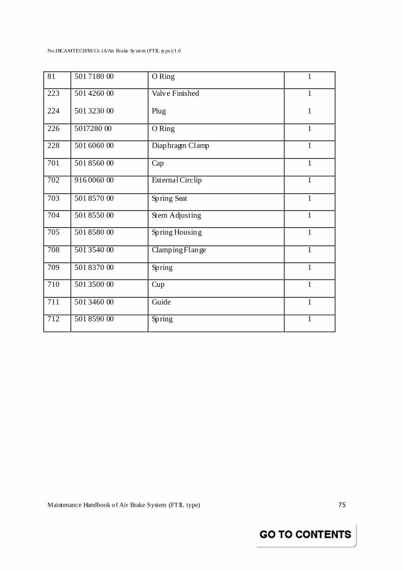
No.IRCAMTECH/M/13-14/Air Brake Sy stem (FTIL ty pe)/1.0
Maintenance Handbook o f Air Brake System (FTIL type) 75
81 501 7180 00 O Ring 1
223 501 4260 00 Valve Finished 1
224 501 3230 00 Plug 1
226 5017280 00 O Ring 1
228 501 6060 00 Diaphragm Clamp 1
701 501 8560 00 Cap 1
702 916 0060 00 External Circlip 1
703 501 8570 00 Spring Seat 1
704 501 8550 00 Stem Adjusting 1
705 501 8580 00 Spring Housing 1
708 501 3540 00 Clamping Flange 1
709 501 8370 00 Spring 1
710 501 3500 00 Cup 1
711 501 3460 00 Guide 1
712 501 8590 00 Spring 1
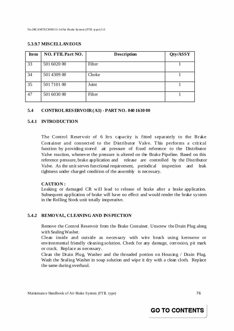
No.IRCAMTECH/M/13-14/Air Brake Sy stem (FTIL ty pe)/1.0
Maintenance Handbook o f Air Brake System (FTIL type) 76
5.3.9.7 MISCELLANEOUS
Item NO. FTIL Part NO. Description Qty/ASSY
33 501 6020 00 Filter 1
34 501 4309 00 Choke 1
35 501 7101 00 Joint 1
47 501 6030 00 Filter 1
5.4 CONTROL RESERVOIR (A3) - PART NO. 040 1630 00
5.4.1 INTRODUCTION
The Control Reservoir of 6 ltrs capacity is f itted separately to the Brake Container and connected to the Distributor Valve. This performs a crit ical function by providing stored air pressure of fixed reference to the Distributor Valve reaction, whenever the pressure is altered on the Brake Pipeline. Based on this reference pressure, brake application and release are controlled by the Distributor Valve. As the unit serves functional requirement, periodical inspection and leak tightness under charged condition of the assembly is necessary. CAUTION : Leaking or damaged CR will lead to release of brake after a brake application. Subsequent application of brake will have no effect and would render the brake system in the Rolling Stock unit totally inoperative.
5.4.2 REMOVAL, CLEANING AND INS PECTION
Remove the Control Reservoir from the Brake Container. Unscrew the Drain Plug along with Sealing Washer. Clean inside and outs ide as necessary with wire brush using kerosene or environmental friendly cleaning solution. Check for any damage, corrosion, pit mark or crack. Replace as necessary. Clean the Drain Plug, Washer and the threaded portion on Housing / Drain Plug. Wash the Sealing Washer in soap solution and wipe it dry with a clean cloth. Replace the same during overhaul.
No.IRCAMTECH/M/13-14/Air Brake Sy stem (FTIL ty pe)/1.0
Maintenance Handbook o f Air Brake System (FTIL type) 77
5.4.3 TESTING
During overhaul, an air pressure test is required to be conducted. Fix a dummy plate with flat surface and gasket to seal the open end of the CR. With a suitable adapter and flexible connection at the 1/2" drain port, admit an air pressure of 10 kg/cm². No leakage by way of a bubble formation is allowed on outside surface with soap water application. Remove dummy plate / adapter, clean and dry. Refix the Drain Plug with Sealing Washer and tighten. Ensure leak proof joint.
Cover the open end of the Reservoir and ports, using suitable Closure Plugs. Retain the Closure Plugs till the CR is reassembled.
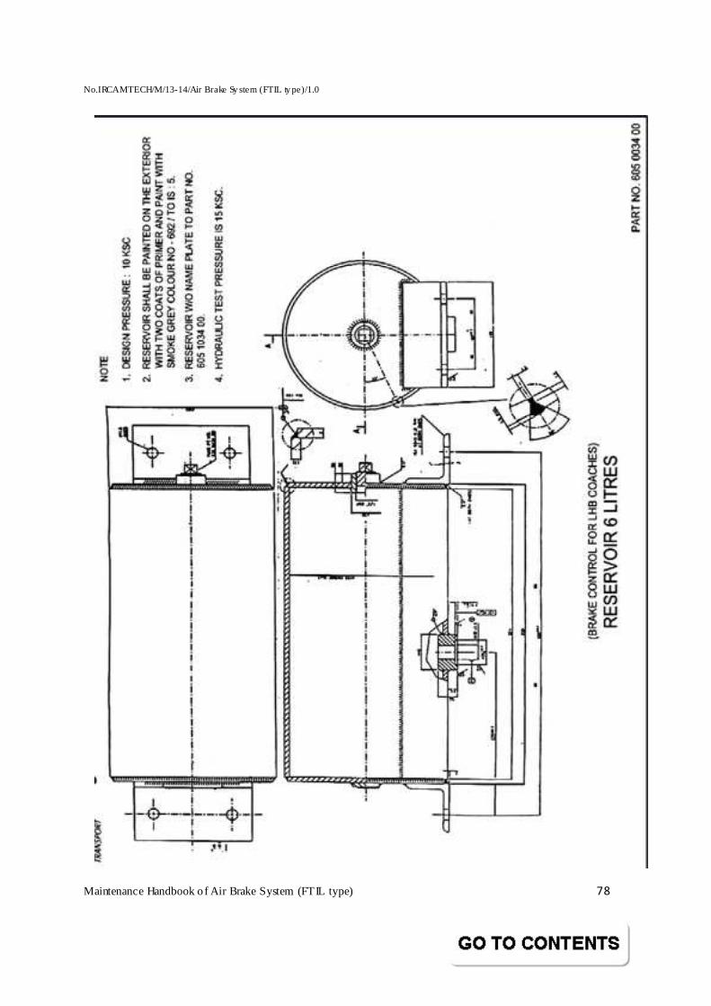
No.IRCAMTECH/M/13-14/Air Brake Sy stem (FTIL ty pe)/1.0
Maintenance Handbook o f Air Brake System (FTIL type) 78
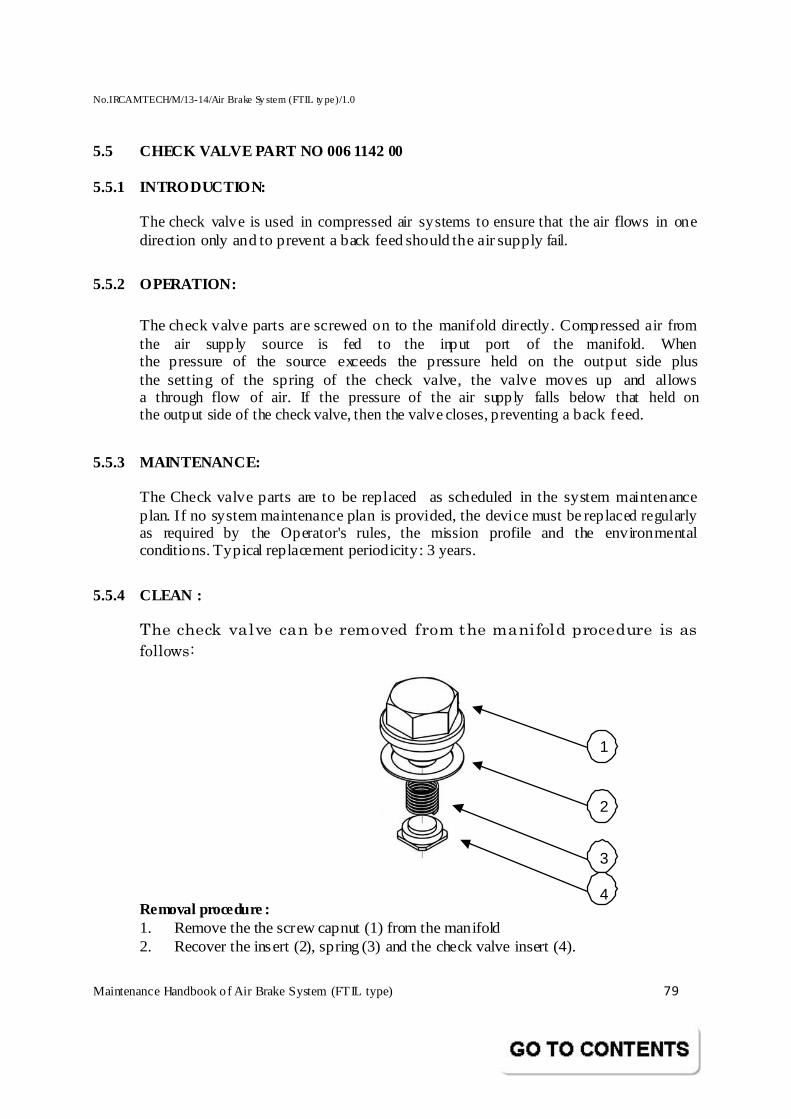
No.IRCAMTECH/M/13-14/Air Brake Sy stem (FTIL ty pe)/1.0
Maintenance Handbook o f Air Brake System (FTIL type) 79
5.5 CHECK VALVE PART NO 006 1142 00
5.5.1 INTRODUCTION:
The check valve is used in compressed air systems to ensure that the air flows in one direction only and to prevent a back feed should the air supply fail.
5.5.2 OPERATION:
The check valve parts are screwed on to the manifold directly. Compressed air from the air supply source is fed to the input port of the manifold. When the pressure of the source exceeds the pressure held on the output side plus the setting of the spring of the check valve, the valve moves up and allows a through flow of air. If the pressure of the air supply falls below that held on the output side of the check valve, then the valve closes, preventing a back feed.
5.5.3 MAINTENANCE:
The Check valve parts are to be replaced as scheduled in the system maintenance plan. If no system maintenance plan is provided, the device must be replaced regularly as required by the Operator's rules, the mission profile and the environmental conditions. Typical replacement periodicity: 3 years.
5.5.4 CLEAN :
The check valve can be removed from the manifold procedure is as
follows:
1
2
3 4
Removal procedure : 1. Remove the the screw capnut (1) from the manifold 2. Recover the insert (2), spring (3) and the check valve insert (4).
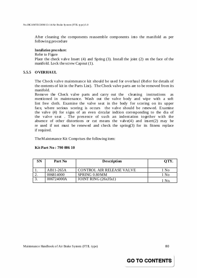
No.IRCAMTECH/M/13-14/Air Brake Sy stem (FTIL ty pe)/1.0
Maintenance Handbook o f Air Brake System (FTIL type) 80
After cleaning the components reassemble components into the manifold as per following procedure Installation procedure: Refer to Figure Place the check valve Insert (4) and Spring (3). Install the joint (2) on the face of the manifold. Lock the screw Capnut (1).
5.5.5 OVERHAUL The Check valve maintenance kit should be used for overhaul (Refer for details of the contents of kit in the Parts List). The Check valve parts are to be removed from its manifold. Remove the Check valve parts and carry out the cleaning instructions as mentioned in maintenance. Wash out the valve body and wipe with a soft lint free cloth. Examine the valve seat in the body for scoring on its upper face, where serious scoring is occurs the valve should be renewed. Examine the valve (4) for s igns of an even circular indtion corresponding to the dia of the valve seat . The presence of such an indentation together with the absence of other distortions or cut means the valve(4) and insert(2) may be re used if not must be renewed and check the spring(3) for its fitness replace if required. The M aintenance Kit Comprises the following item:
Kit Part No : 790 006 10
SN Part No Description QTY.
1. AB11-265A CONTROL AIR RELEASE VALVE 1 No 2. 006814000 SPRING 0.80 MM 1 No 3. 006724000A JOINT RING (26x35x1) 1 No.
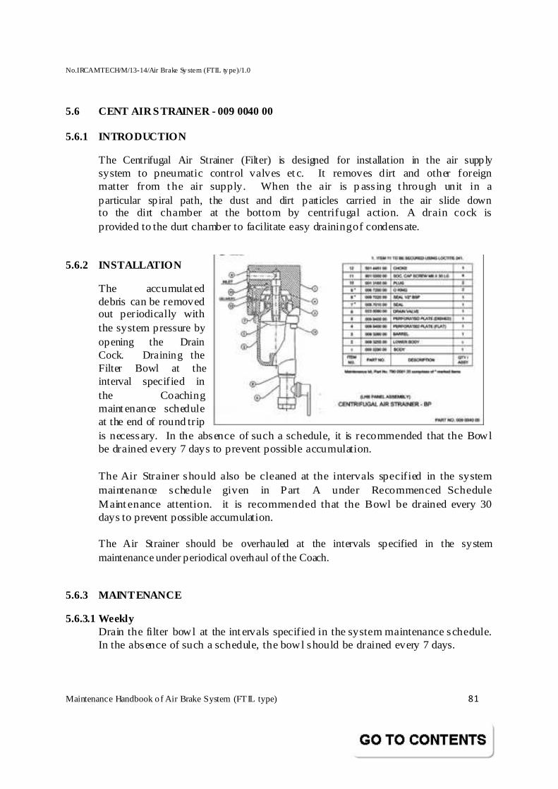
No.IRCAMTECH/M/13-14/Air Brake Sy stem (FTIL ty pe)/1.0
Maintenance Handbook o f Air Brake System (FTIL type) 81
5.6 CENT AIR STRAINER - 009 0040 00
5.6.1 INTRODUCTION
The Centrifugal Air Strainer (Filter) is designed for installation in the air supply system to pneumatic control valves et c. It removes dirt and other foreign matter from the air supply. When the air is p assing t hrough unit in a particular spiral path, the dust and dirt particles carried in the air slide down to the dirt chamber at the bottom by centrifugal action. A drain cock is provided to the durt chamber to facilitate easy draining of condensate.
5.6.2 INSTALLATION
The accumulated debris can be removed out periodically with the system pressure by opening the Drain Cock. Draining the Filter Bowl at the interval specified in the Coaching maintenance schedule at the end of round trip is necessary. In the absence of such a schedule, it is recommended that the Bowl be drained every 7 days to prevent possible accumulation.
The Air Strainer should also be cleaned at the intervals specified in the system maintenance schedule given in Part A under Recommenced Schedule Maintenance attention. it is recommended that the Bowl be drained every 30 days to prevent possible accumulation.
The Air Strainer should be overhauled at the intervals specified in the system maintenance under periodical overhaul of the Coach.
5.6.3 MAINTENANCE 5.6.3.1 Weekly
Drain the filter bowl at the intervals specified in the system maintenance schedule. In the absence of such a schedule, the bowl should be drained every 7 days.
No.IRCAMTECH/M/13-14/Air Brake Sy stem (FTIL ty pe)/1.0
Maintenance Handbook o f Air Brake System (FTIL type) 82
5.6.3.2 Monthly The air strainer should be cleaned out at the intervals specified in the system maintenance schedule. In the absence of such a schedule, the drain cup should be cleaned every 30 days.
5.6.3.3 6 years The air strainer should be overhauled at the intervals specified in the system maintenance schedule. In the absence of such a schedule, the strainer should be overhauled every 6 years.
5.6.4 DRAIN BOWL
The following table With the air pressure isolated and vented, remove the Drain Cock allowing condensate to drain out. Clean the Bowl and refix the Drain Cock.
5.6.5 CLEAN
The Air Strainer can be cleaned without removing the units from its manifold mounting. However, the air supply must be isolated and vented to atmosphere before this procedure.
Undo M8 Screws (11) and remove the Drain Cup (10) together with Lower Body (2) and p erforated plates (4 & 5). Reassemble aft er cleaning the components using a new Seal (7). Ensure the air supply is restored and no air leak is present around the Drain Cup.
5.6.6 OVERHAUL
The maintenance kit should be used for overhaul (Refer for details of the contents of kit in the Parts List). The Air Strainer should be removed from its manifold mounting on the Panel.
Remove the Drain Valve and Bowl. Carry out the cleaning instructions described above under Maintenance. Clean the Body (1), p aying particular attention to the mating faces.
Reassemble the Air Strainer using new Seals (7 & 8). When refitting to the manifold on Panel, new O Ring should be used.
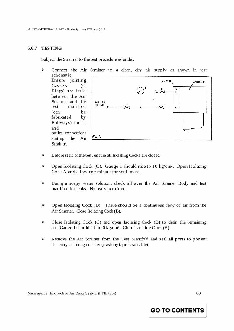
No.IRCAMTECH/M/13-14/Air Brake Sy stem (FTIL ty pe)/1.0
Maintenance Handbook o f Air Brake System (FTIL type) 83
5.6.7 TESTING
Subject the Strainer to the test procedure as under.
� Connect the Air Strainer to a clean, dry air supply as shown in test schematic. Ensure jointing Gaskets (O Rings) are fitted between the Air Strainer and the test manifold (can be fabricated by Railways) for in and outlet connections suiting the Air Strainer.
� Before start of the test, ensure all Isolating Cocks are closed. � Open Isolating Cock (C). Gauge 1 should rise to 10 kg/cm². Open Isolating
Cock A and allow one minute for settlement.
� Using a soapy water solution, check all over the Air Strainer Body and test manifold for leaks. No leaks permitted.
� Open Isolating Cock (B). There should be a continuous flow of air from the Air Strainer. Close Isolating Cock (B).
� Close Isolating Cock (C) and open Isolating Cock (B) to drain the remaining air. Gauge 1 should fall to 0 kg/cm². Close Isolating Cock (B).
� Remove the Air Strainer from the Test Manifold and seal all ports to prevent the entry of foreign matter (masking tape is suitable).
No.IRCAMTECH/M/13-14/Air Brake Sy stem (FTIL ty pe)/1.0
Maintenance Handbook o f Air Brake System (FTIL type) 84
5.7 FILTER KIT TO PART NO 009 0070 00
5.7.1 INTRODUCTION :
Compressed air contains dirt, dust, rust, condensates, moisture contents, oil impurities & exhaust fumes. The air f ilt er cleans and remove the foreign particles enter into the air supply to the system.
5.7.2 OPERATION :
The Filter parts are screwed on to the manifold directly. Compressed air from the air supply source is fed to the input port of the manifold. When the air is passing through filter (vion) element its getting filtered .
5.7.3 INSTALLATION
The accumulated debris can be removed out periodically with the system p ressure by op ening t he cap nut . Drain t he condensate/dusts at the interval specified in the Coaching maintenance schedule. In the absence of such a schedule, it is recommended that the condensate/dusts drained every 7 days to prevent possible accumulation.
The Air FILTER should be overhauled at the intervals specified in the system maintenance under periodical overhaul of the Coach.
5.7.4 MAINTENANCE
5.7.4.1 Weekly
The filter should be examine for loose fastenings or leakages and drain the condensate & dusts as sp ecified in t he system maintenance schedule. In the absence of such a schedule, the plan shall be 7 days.
5.7.4.2 Monthly
The FIlter should be Examine & clean at the intervals specified in the system maintenance schedule. In the absence of such a schedule, The plan shall be every month.
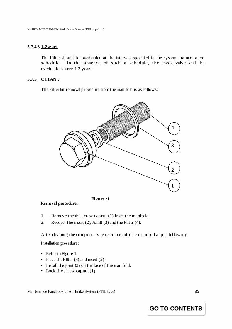
No.IRCAMTECH/M/13-14/Air Brake Sy stem (FTIL ty pe)/1.0
Maintenance Handbook o f Air Brake System (FTIL type) 85
5.7.4.3 1-2years The Filter should be overhauled at the intervals specified in the system maintenance schedule. In the absence of such a schedule, t he check valve shall be overhauled every 1-2 years.
5.7.5 CLEAN : The Filter kit removal procedure from the manifold is as follows:
Removal procedure :
1. Remove the the screw capnut (1) from the manifold
2. Recover the insert (2), Jointt (3) and the Filter (4).
After cleaning the components reassemble into the manifold as per following
Installation procedure : • Refer to Figure 1. • Place the FIlter (4) and insert (2). • Install the joint (2) on the face of the manifold. • Lock the screw capnut (1).
4
3
2
1
Figure :1
No.IRCAMTECH/M/13-14/Air Brake Sy stem (FTIL ty pe)/1.0
Maintenance Handbook o f Air Brake System (FTIL type) 86
5.7.6 OVERHAUL
The Filter maintenance kit should be used for overhaul (Refer for details of the contents of kit in the Parts List). The Filter parts are to be removed from its manifold.
Remove and Clean carefully the filt er element (3) wit h a clean, dry compressed air line and replace the if it is heavily soiled or contaminated with oils and examine the assembly and remove any foreign matter blowing out any solid deposits.
The M aintenance Kit Comprises the following item Kit Part No : 790 009 106
SN Part No Description QTY.
1 029702500A Insert 1
2 029602000 Filter 1
3 029702000A Joint Ring 1
No.IRCAMTECH/M/13-14/Air Brake Sy stem (FTIL ty pe)/1.0
Maintenance Handbook o f Air Brake System (FTIL type) 87
5.8 RELAY VALVE TO PART NO 018 0040 00
5.8.1 INTRODUCTION:
The pneumat ic Relay Valve enables a demand for relatively large amount of comp ressed air to be adequately met and regulated efficiently by a Control Valve of limited capacity. The volume of compressed air required for braking purposes is often far greater than that could be met by the normal Driver’s Brake Valve or other Control Device. To meet such a demand, a Relay Valve is used in combination with Driver’s Brake Valve and a Distributor Valve and is controlled under the signal pressure.
Sensitive to signal input pressure, the Relay Valve admits air from the compressed air supply to the Brake Actuators in direct proportion to the signal input pressure. The Valve ensures rapid Brake
Actuator filling and exhaust under all braking conditions.
5. 8 .2 OPERATI ON
Air connections are to the Relay Valve are made via the control unit manifold with the exception of the Relay Valve exhaust which is direct to atmosphere. The air connections are:
The variable pressure Regulator and Auxiliary Reservoir air connection which is sealed by O Ring (34),
The Brake Actuator connection which is sealed by O Ring (3) connected to the Chamber on the upper side of Separating Cover (16),
The Control Reservoir / Regulating air connection which is sealed by O Ring (3) and connected to the chamber below the Pressure Plate (20).
The Valve Spindle (22) is hollow with attachment of two Pressure Plates (20 & 22). One end of the Valve Spindle is open to atmosphere while the other end makes or breaks contact wit h the Valve Seat Assembly (2) under brake application or release conditions. The Pressure Plate (22) is subject to Control Reservoir pressure both under application and release conditions. The Valve Cover (25) contains the exhaust port.
No.IRCAMTECH/M/13-14/Air Brake Sy stem (FTIL ty pe)/1.0
Maintenance Handbook o f Air Brake System (FTIL type) 88
5.8.2.1 BRAKE AP PLIC ATION
During brake application air pressure in chamber A increases. The pressure, act in g on t he surface area of t he Pressure Plate (20), forces it and the att ached Hollow Valve Sp indle (18) t o move in the direct ion of the Valve Assembly (4). The Hollow Valve Spindle Tip, already in contact with the Valve Assembly surface before brake application, lifts the Valve Assembly from the Valve Seat (2). With the Valve now op en, chambers B and C are connected and M ain Reservoir air can reach the Brake Actuators for initiating braking.
As air pressure in chamber B and on the Pressure Plate (22) tends to equalize, the Valve Spindle (18), attached to this Pressure Plate, moves towards its prebraking position.
During this movement, the Valve Assembly (4) under the force of the Compression Spring (05), remains in contact with the Valve Spindle Tip, preventing any venting of air to atmosphere via the Hollow Valve Spindle. Finally, at pressure equalization, the Valve closes completely, cutting off all connection between chambers B and C yet maintaining brake application.
Because the Relay Valve is highly sensitive, Brake Actuator pressure can be increased in small increments in direct relation to chamber A pressure. Also, in the event of leaks, i.e. Piston Seals, Pipe connections etc., the Valve Assembly (4) will be eased from its Seat to maintain Brake Actuator pressure.
5.8.2.2 BRAKE RELEASE
During brake release, the air pressure in chamber A decreases and the force acting on Pressure Plate (20) becomes smaller than that acting on Pressure Plate (22). This pressure imbalance causes the tip of the Valve Spindle (10) to loose contact with the Valve Assembly (4). Comp ressed air from the Brake Actuator and from chamber B is now free to vent to atmosphere via the Hollow Valve Spindle while chamber B is isolated from chamber C by the seated Valve Assembly.
Compressed air vents unt il the respect ive pressures in chambers A and B equalize allowing the Valve spindle tip to re-establish contact with the Valve assembly surface and to seal off atmospheric contact.
Thus pressure reduction in chamber A results in a corresponding pressure reduction in chamber B and sensitive Valve design means that small pressure reductions allow the brakes to be released step-by-step as required.
No.IRCAMTECH/M/13-14/Air Brake Sy stem (FTIL ty pe)/1.0
Maintenance Handbook o f Air Brake System (FTIL type) 89
5.8.3 MAIN TEN ANC E
The Valve requires no rout ine maintenance between overhauls of the Rolling Stock and should be carried out at the intervals sp ecified in t he system maintenance schedule.
The only routine maintenance required is a period check to ensure that the exhaust port is not continuously venting during braking as this indicates poor Valve Seating Joint. The Relay Valve should be overhauled at the intervals specified in the system maintenance schedule.
The Relay Valve is removed from its mounting by releasing two Hex. Headed Bolts and the Valve port s should be sealed with adhesive tap e unt il t he overhaul procedure is carried out.
5. 8 .4 OVERHAUL
Dismantle the Valve by reference to part drg no. 018 0040 00.
5. 8. 5 RE-ASSEMBLY
Reassemble the Valve with reference to the drawing by using new Gaskets, O Rings and Seals in the reverse order of disassembly.
5 .8 .6 TEST PROCEDURE
After overhaul, subject the Relay Valve to the test procedure attached.
5.8.7 REASSEMBLY ON BRAKE PANEL
The tested and passed Valves is to be mounted to the Integral Sandwich Piece with Isolating Cock Assembly with two Hex. Bolts with the Sealing Gasket in position.
The tightening torque for the M10 Fixing Screws is 20 ft. lbs.
NOTE:
The Relay Valve p erformance is also to be checked during t he overall brake system test of the individual Coach.
5. 8. 8 PROCEDURE FOR TESTING
Refer test schematic attached.
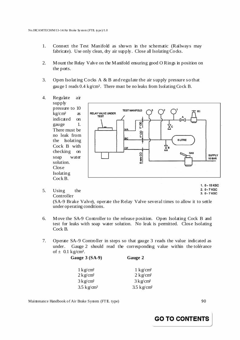
No.IRCAMTECH/M/13-14/Air Brake Sy stem (FTIL ty pe)/1.0
Maintenance Handbook o f Air Brake System (FTIL type) 90
1. Connect the Test Manifold as shown in the schematic (Railways may fabricate). Use only clean, dry air supply. Close all Isolating Cocks.
2. Mount the Relay Valve on the Manifold ensuring good O Rings in position on
the ports. 3. Open Isolat ing Cocks A & B and regulate the air supply pressure so that
gauge 1 reads 0.4 kg/cm². There must be no leaks from Isolating Cock B. 4. Regulate air
supply pressure to 10 kg/cm² as indicated on gauge 1. There must be no leak from the Isolating Cock B with checking on soap water solution. Close Isolating Cock B.
5. Using the Controller (SA-9 Brake Valve), operate the Relay Valve several times to allow it to settle under operating conditions.
6. Move the SA-9 Controller to the release position. Open Isolating Cock B and test for leaks with soap water solution. No leak is permitted. Close Isolating Cock B.
7. Operate SA-9 Controller in steps so that gauge 3 reads the value indicated as under. Gauge 2 should read the corresponding value within the tolérance of ± 0.1 kg/cm².
Gauge 3 (SA-9) Gauge 2
1 kg/cm² 1 kg/cm² 2 kg/cm² 2 kg/cm² 3 kg/cm² 3 kg/cm² 3.5 kg/cm² 3.5 kg/cm²
No.IRCAMTECH/M/13-14/Air Brake Sy stem (FTIL ty pe)/1.0
Maintenance Handbook o f Air Brake System (FTIL type) 91
NOTE:
When operating the Controller SA-9, the air pressure on gauge 3 must never be reduced to achieve the required figures.
8. Operate SA-9 Controller to lower the air pressure on gauge 3 to the values shown as under. Gauge 2 should read the corresponding value within the tolerance of ± 0.1 kg/cm².
Gauge 3 (SA-9) Gauge 2 3 kg/cm² 3 kg/cm² 2 kg/cm² 2 kg/cm² 1 kg/cm² 1 kg/cm²
NOTE: When operating the Controller SA-9, the air pressure in gauge 3 must never be increased to achieve the required figures.
9. Close Isolating Cock A and open Isolating Cock B & C. Ensure the SA-9 Controller is in release and that gauge 3.0 reads 0.0 kg/cm².
10. Remove the Relay Valve from the Test Manifold and seal all ports to prevent re-entry of foreign matter till its reuse.

No.IRCAMTECH/M/13-14/Air Brake Sy stem (FTIL ty pe)/1.0
Maintenance Handbook o f Air Brake System (FTIL type) 92
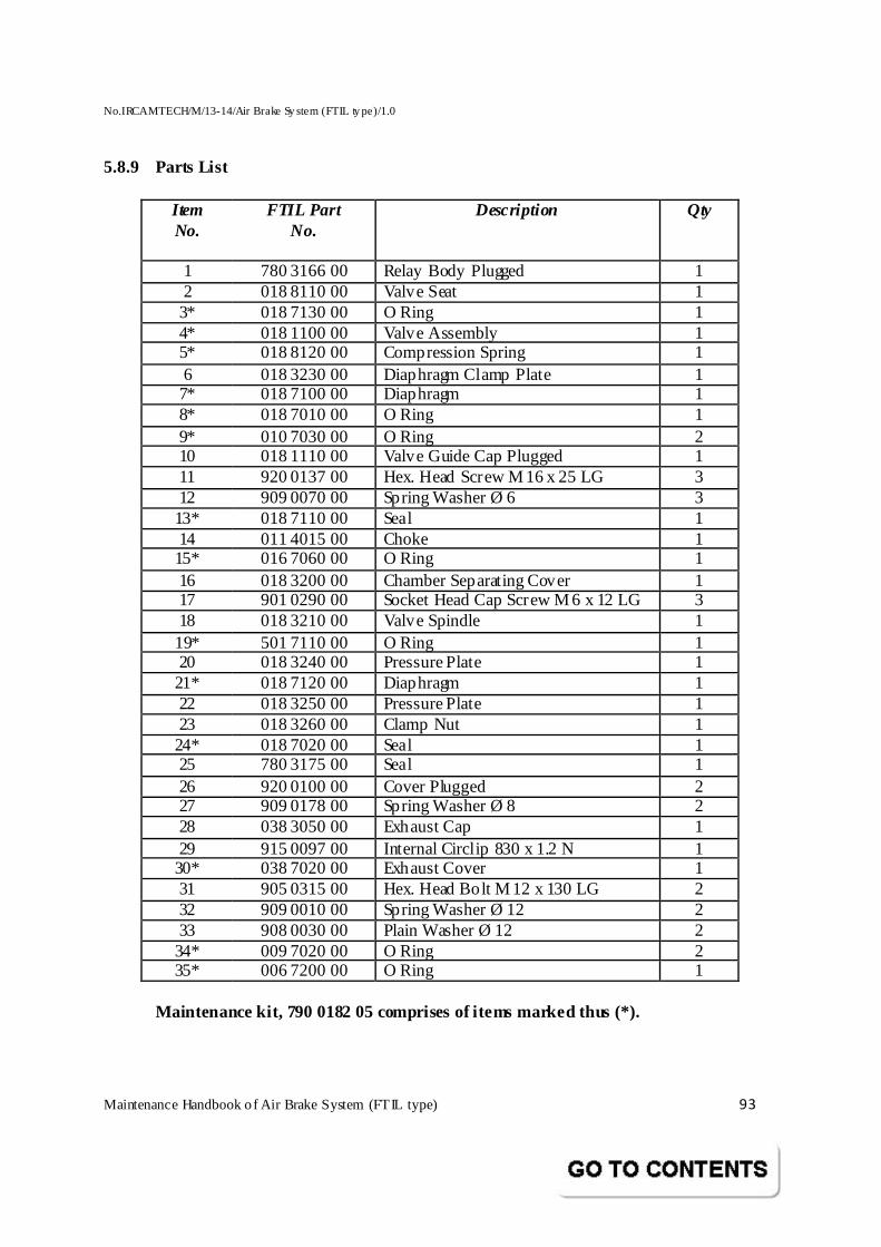
No.IRCAMTECH/M/13-14/Air Brake Sy stem (FTIL ty pe)/1.0
Maintenance Handbook o f Air Brake System (FTIL type) 93
5.8.9 Parts List
Item No.
FTIL Part No.
Description Qty
1 780 3166 00 Relay Body Plugged 1 2 018 8110 00 Valve Seat 1 3* 018 7130 00 O Ring 1 4* 018 1100 00 Valve Assembly 1 5* 018 8120 00 Compression Spring 1 6 018 3230 00 Diaphragm Clamp Plate 1 7* 018 7100 00 Diaphragm 1 8* 018 7010 00 O Ring 1 9* 010 7030 00 O Ring 2 10 018 1110 00 Valve Guide Cap Plugged 1 11 920 0137 00 Hex. Head Screw M 16 x 25 LG 3 12 909 0070 00 Spring Washer Ø 6 3 13* 018 7110 00 Seal 1 14 011 4015 00 Choke 1 15* 016 7060 00 O Ring 1 16 018 3200 00 Chamber Separating Cover 1 17 901 0290 00 Socket Head Cap Screw M 6 x 12 LG 3 18 018 3210 00 Valve Spindle 1 19* 501 7110 00 O Ring 1 20 018 3240 00 Pressure Plate 1 21* 018 7120 00 Diaphragm 1 22 018 3250 00 Pressure Plate 1 23 018 3260 00 Clamp Nut 1 24* 018 7020 00 Seal 1 25 780 3175 00 Seal 1 26 920 0100 00 Cover Plugged 2 27 909 0178 00 Spring Washer Ø 8 2 28 038 3050 00 Exhaust Cap 1 29 915 0097 00 Internal Circlip 830 x 1.2 N 1 30* 038 7020 00 Exhaust Cover 1 31 905 0315 00 Hex. Head Bolt M 12 x 130 LG 2 32 909 0010 00 Spring Washer Ø 12 2 33 908 0030 00 Plain Washer Ø 12 2 34* 009 7020 00 O Ring 2 35* 006 7200 00 O Ring 1
Maintenance kit, 790 0182 05 comprises of items marked thus (*).
No.IRCAMTECH/M/13-14/Air Brake Sy stem (FTIL ty pe)/1.0
Maintenance Handbook o f Air Brake System (FTIL type) 94
5.9 PRESSURE SWITCH TO PART NO 040 1090 00
5.9.1 INTRODUCTION
The single pole, double throw snap NO/NC switch has double break contacts offering one normally open circuit and one normally closed circuit. The Pressure Switch has an adjustable “switch - on" pressure and an independently adjustable differential to the “switch - off" pressure.
5. 9. 2 FUNC TION
The Pressure Switch controls the electrical circuit of WSP unit operation for an OFF/ ON mode. It is connected in the Feed Pipe Circuit and normally open type. As soon as t he pressure in Feed Pipe rises t o a level of 1.8 kg/cm², the contacts are closed automatically and WSP electrical circuit gets energized by the electrical supply of the LHB Coach and brings it to functional mode. When the FP pressure drops down to 1.3 kg/cm² during reduction stage, the Pressure Switch assumes the OFF mode. This disconnects the electrical circuit governing the WSP operation in the Coach and makes it non-operational.
5. 9. 3 RA TIN GS
5.9.3.1 PRESSU RE
M aximum allowable pressure 11 (kg/cm²)
WARNIN G If the Pressure Switch Actuators are exposed to system or surge pressure greater
than the maximum allowable pressure indicated, leakage from the actuator and / or change in operating values may result. The more frequent the application and the greater the value of excessive pressure, the more actuator life will be decreased.
5. 9.3.2 ELECTRICAL
The normal rating of the switch is limited to 110-230 volts DC and 2 amps. maximum operation.
5.9.3.3 TEMPERATUR E
Pressure Swit ches, are suit able for cont inuous use, provided that the process fluid does not freeze and the conditions of application do not give rise to the formation of frost or ice inside the Pressure Switch, due to operating ambient factors.
No.IRCAMTECH/M/13-14/Air Brake Sy stem (FTIL ty pe)/1.0
Maintenance Handbook o f Air Brake System (FTIL type) 95
5.9.4 INSTALLATION
WIRING The terminals of the swit ch will accept 1.0 to 2.5 mm solid or stranded copper wire. However 1 sq. mm of stranded copper wire has been used in the supplies. For securing the wires to the terminals, tighten to 0.7 to 1.0 Nm torque. The terminals are not suitable for use with aluminium wire.
5.9.5 MAIN TEN ANC E:
The Pressure Switch requires only checking of its operating pressures in service. No other maintenance is desirable. If a Pressure Switch fails to operate correctly in service despite adjustment, it is recommended for renewal.
5.9.5.1 OPERATING PRESSURE ADJUSTMENT:
SET POINT ADJUSTMENT
The Pressure Switch is set at the factory to operate at the correct pressures as per t he requirement of Railways. It is good p ractice to cy cle t he swit ch t o determine the actual operating points before proceeding with re-adjustment.
Im porta nt: A djust switchi ng pressure o nly under stea dy s upply pressure.
ADJUSTMENT PROCEDURE
• Remove the Dust Cover.
• Operate the Pressure Switch few times to settle before varying / adjusting the Pressure Switch.
• Ensure that the supply air pressure (in Coach or test set up) is steady and constant.
• Connect continuity tester (buzzer) across common and NO terminal.
TO SET RIS ING PRESSURE (1.3 kg/cm²)
• Remove Safety Lock Screw from the Flower Knob.
• Hold the Hexagonal Nut (beneath the Flower Knob) with appropriate spanner.
• Slowly bleed the pressure. Check the point when NO contact is made ( listen to buzzer noise).
No.IRCAMTECH/M/13-14/Air Brake Sy stem (FTIL ty pe)/1.0
Maintenance Handbook o f Air Brake System (FTIL type) 96
• If needed, rotate the Flower Knob to increase or to decrease the pressure based on the direction shown on the wheel for the correct value.
• Replace the Safety Lock Screw and secure the Flower Knob.
TO SET THE FALLING PRESSURE (1.9 kg/cm²)
• Slowly increase the pressure. Check the following pressure points.
• Adjust the Hexagonal Nut with help of appropriate spanner. To increase or decrease the pressure, if needed, following the direction mentioned in the Flower Knob.
• Adjust the Hexagonal Nut to 1.9 kg/cm² till NO contact is made.
5.9.5.2 REPLACEMENT OF PRESSURE SWITCH
If a Pressure Switch is changed, it is essential that its operating pressures are set correctly. The procedure for replacement is as follows:-
• Open the cover by releasing 4 screws.
• Disconnect the electrical wiring from the terminal block, note the wiring arrangements so that a new switch can be connected correctly.
• Disconnect the air connection.
• Release 2 screws holding the Pressure Switch in position and remove the switch.
• Fit a new switch in the reverse order, and ensure the electrical wir ing is correct.
• Check switch opens and closes at the correct pressures after fitment in the Coaching braking system as per adjustment procedure.
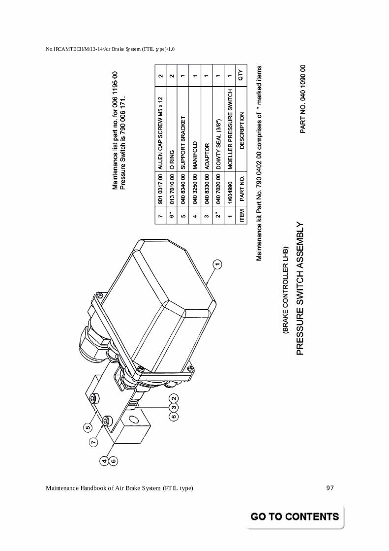
No.IRCAMTECH/M/13-14/Air Brake Sy stem (FTIL ty pe)/1.0
Maintenance Handbook o f Air Brake System (FTIL type) 97
No.IRCAMTECH/M/13-14/Air Brake Sy stem (FTIL ty pe)/1.0
Maintenance Handbook o f Air Brake System (FTIL type) 98
5.10 HEALTH AND SAFETY
The following points must be considered and appropriate precautions should be taken when working on this equipment during disassembly, overhaul assembly and tests. These should not be taken as an exclusive list of hazards.
1. 1 Individual sect ions of this publication may include specific healt h and safety information relating to that section. It is important that these pages are read and appropriate actions taken.
1. 2 This is compressed air equipment. Compressed air is dangerous. “Bottled up” air
under pressure despite supply cut-off, may cause component, diaphragm, trapped foreign particles, etc., to be air borne during disassembly.
1. 3 Some components / sub-assemblies use powerful springs in a compressed state.
Care must be t aken to release the forces in a controlled manner during disassembly.
1. 4 Oils and greases are used which could be a hazard. 1. 5 Air jet used for cleaning parts should be less than 30 psi. Higher air pressure
may cause particles of dirt or droplets of cleaning solution to be air borne and result in skin / eye irritation.
1. 6 Chemical cleaning agents may be used for certain operations, which need a
strict compliance to the manufacturer’s handling procedures. 1. 7 Before performing any test / repair on brake system of rolling stock, steps
against possible “run away of the vehicle” are to be taken. In addition, staffs working in undergear area are to be cautioned of likely brake rigging movement.
No.IRCAMTECH/M/13-14/Air Brake Sy stem (FTIL ty pe)/1.0
Maintenance Handbook o f Air Brake System (FTIL type) 99
5.11 GENERAL HINTS ON MAINTENANCE OF AIR BRAKE SYST EM
ROUTINE MAINTENANCE
The high standard and performance obtained from air brake equipment will be maintained in service with the minimum of maintenance providing that water / dirt are kept out of the equip ment and that the compressed air supply is kept reasonably clean from dust, oil and condensate. At regular intervals, f ilters must be removed, cleaned and checked for damage before being renewed or rep laced. Drain cocks should be opened at regular intervals to remove collected condensate and other foreign matter.
The use of blanking piece or sealing tape is recommended to seal open ports to prevent ingress of moisture and foreign matter into t he comp onents of t he brake system.
When carrying out maintenance, the instructions given in the catalogue applicable to a part icular item should be followed.
INSTALLATION
PTFE tape is not recommended to be used on any pipe joints associated with air brake system. A suitable pipe sealant is “Loctite 577” or equivalent.
SPARES
Only approved and recommended overhaul kit / spare parts as given in the parts catalogue should be used during overhaul / renewing components.
No.IRCAMTECH/M/13-14/Air Brake Sy stem (FTIL ty pe)/1.0
Maintenance Handbook o f Air Brake System (FTIL type) 100
5.12 GENERAL TOOLS FOR ATTENTION TO AIR BRAKE EQUIP MENT AND
FACILITIES
FOR OVERHAULING LHB COACH BRAKE SYSTEM IN OPEN LINE DEPOT / WORKSHOP The general tools as under are required for necessary attention during routine maintenance checks at terminals as well as for periodic attention during IOH / POH. The required number of tools in each category may be arrived at, after taking into consideration, type of activity, number of out of course repairs, online attention and staff strength employed. GENERAL TOOLS (For Base Depot / yard online examination / IOH Depot)
M inimum requirement at each center
Spanner Single End A/F 6, 10, 13, 14, 19, 24, 35, 55, 60, 64
Socket Wrench across flats A/F 16 & 17, 24 & 27
Ring Spanner A/F 19 / 27 & 37
Socket Wrench across flats A/F 17, 19, 22, 27, 32 and 50
Standard Pipe Wrench 12” and 18”
Bench Vice 6”
Ball Pene Hammer 500 gm
Nylon Hammer
Chisel flat
Flat & Half round files rough / smooth
Screw Driver 1.2 x 4 mm x 160
Resetting Key for Pilot Valve Passenger Alram
Adaptor with Flexible Pipe & Test Pressure Gauge for checking at test points.
No.IRCAMTECH/M/13-14/Air Brake Sy stem (FTIL ty pe)/1.0
Maintenance Handbook o f Air Brake System (FTIL type) 101
5.12.1 ADDITIONAL GENERAL TOOLS FOR PERIODIC OVERHA UL AT WORKSHOPS
All the general tools mentioned above for base Depots :
Allen Key set 2 sets
Pliers 6” straight nose 2 Nos
Pliers 6” bent nose 2 Nos
Circlip pliers for internal circlip of sizes
B40 IS 3075 all light series 2 sets
B14 IS 3075 all light series 2 sets
B28 IS 3075 all light series 2 sets
Torque wrench 9.3 M Kg 2 Nos
The Special Tools and Fixtures additionally required during the overhaul of
the brake equipment are covered as under in the relevant chapters. The
sketches are attached in the respective equipment chapters.
FOR C3W - DV
Bench M ounting Fixture for holding C3W during overhaul.
Special tools for overhaul under FTIL Part nos. SCT 6092, SCT 6015, RPBF 0003,
SCT 6026, SCT 6016, ACT 6017, SCT 6093.
Assembly and Disassembly special fixture FTIL - RPBF 0202
Extractors during dis-assembly
Hand Press
Pressing Fixtures during assembly.
Special Tool for dia 20mm Cock and Special Box Spanner.
No.IRCAMTECH/M/13-14/Air Brake Sy stem (FTIL ty pe)/1.0
Maintenance Handbook o f Air Brake System (FTIL type) 102
5.13 TEST RIGS FOR IOH & POH REPAIRS
Description FTIL drawing /
sketch no.
Base IOH depot
POH Workshop
M obile Single Car test 795 0003 00 1 1
M obile Rake Test Rig RBTR 0016 1 1
Test Bench for functional tests of BC, End Angle Cock, Air Strainer, Isolating Cock, Check Valve, PEASD, PEAV, Guard’s Brake Van Valve, Cut Out Cock, etc. Details are given at each equipment chapter by way of sketches wherever necessary
- 1
.
AIR TEST ARRANGEMENTS
Pneumatic test arrangements for functional checking CR, AR, Hose Coupling BP/FP, PVPA, Emergency Valve.
1
1
Hydraulic test arrangements for checking CR and AR. - 1
FACILITIES COMMON FOR ALL CENTRES Air supply source with a working pressure 10 kg/cm² with a delivery capacity of minimum 2000 litres/min.
Air Reservoir Capacity 350 litres - 1 no (minimum)
OTHER FACILITIES
Facilities like handling, cleaning, lifting equipments, work table with plastic storage bins for keeping components / spares, clean dust-free room for assembly / testing etc., preferably air conditioned, may be decided by Railways in view of the sophistication of work, level of activity at the center.
No.IRCAMTECH/M/13-14/Air Brake Sy stem (FTIL ty pe)/1.0
Maintenance Handbook o f Air Brake System (FTIL type) 103
5.14 CLEANING PROCEDURE (AIR BRAKE EQUIPMENTS /COMP ONENTS)
The cleanin g method dep ends up on the comp onent t o be cleaned, the degree and the type of dirt to be removed and the facilities available. Whatever cleaning agents are used, due care must be t aken to ensure the health and safety of the personnel involved. The manufacturer’s recommended safety precautions including t he use of approved cleaning plant must be followed. Since every installation is different, the responsibility for safety lies with t he user and the manufacturer of the cleaning plant and materials. However, general guidelines on the cleaning procedure for the air brake equipment during maintenance and scheduled overhauls as under are recommended.
Blow the exterior of the equipment / assembly with a low pressure jet of air to remove the external dirt. Aft er removal of sub-assemblies, wipe the exterior portions with a cloth. Clean with environment friendly agents like White spirit, etc /all the stripped components by using a cloth or nylon bristle brush as the case may be based on the sensitivity of it em. If kerosene is used, special care must be taken in protecting the user with proper gloves as well as the environment from the likely fumes. Suff icient care is to be taken to ensure that the residual deposit of kerosene, if trapped inside the cavities / bores of the components, is removed thoroughly before the components being re-used. In addition, the contaminated kerosene aft er use should also be disposed off by proper environment friendly action.
Blow a low pressure jet of dry compressed air inside the machined bores, cored passages, p ort holes, cavit ies and seating grooves on the subassemblies. Wipe the parts with a clean lint free cloth and allow them to dry on a clean rubber sheet on the work table. Take good care to protect the finish on t he various comp onents and place them. Avoid keeping the comp onents piled up one over the other.
All rubber components including rubber seated valves must not be exposed to petroleum or chemical cleaning solvent. It ems like Gasket, “O" Ring, Seal, Diaphragm, Nylon filter / Strainer etc., are to be cleaned only with a detergent dissolved in warm water or soap water solution. Blow a jet of compressed air in the reverse direction on the Nylon Filters and wipe clean with soft cloth.
No.IRCAMTECH/M/13-14/Air Brake Sy stem (FTIL ty pe)/1.0
Maintenance Handbook o f Air Brake System (FTIL type) 104
Chokes / Choke passages are to be cleaned by a blow of clean low pressure air jet. Clogged chokes may be cleaned wit h a wire of smaller diameter without using a sharp tool. Application and Release choke plugs, in DV valve body are to be cleaned, blown with air, and kept free of dirt/dust, grease, paint, etc., by suitable covering till they are fitted.
Caution: While cleaning the equipment / components with chemical / petroleum comp ounds, care must be t aken to prevent inhalat ion of fumes emanating from the cleaning agent and for any possible injury to persons handling the equipment. Similarly, for any chemical fumes likely to cause a fire hazard, steps must also be taken for adequate protect ion to equip ments/ installation. Consult manufacturer’s recommendation in handling such chemicals.
5.15 INSPECTION/REPLACEMENT CRITERIA (AIR BRAKE EQU IPMENT/
COMPONENTS)
Visual inspect ion and replacement criterion as under, is recommended during scheduled overhaul of the equipments used in the air brake system of rolling stock.
Ensure a thorough external and internal cleaning after disassembly and stripping of components with proper cleaning agent.
Inspect visually with the help of a magnifying glass of at least 100mm dia.
All components for any external damages, dents, cracks, corros ion, pit marks, cuts, deep scratches, abnormal wear, sharp corners on mounting / seating / sliding / mating faces.
Threaded portion on comp onents / p arts, for any damages / abnormal wear.
Re place components if, 1. Moving parts appear abnormally worn out or scratches/burrs observed on the
mating parts. 2. Threaded portion on components exhibit damages / abnormal wear. 3. Valve Seat cut or scratched, tips of Hollow Stem / Guide Plunger cracked,
cut, dented or oval f lat / sharp. 4. Spring found in damaged, cracked, heavily rusted, permanent set condition
and Spring seats indicate any damage or abnormal wear. Refer to our separate DV manual under ref. WBS/PBS/006 for spring information.
5. Filter/Strainer found with rupture, damaged seating face, presence of large blocked passages despite cleaning.
6. Rubber items like Gaskets, Diaphragms, etc., found with cut, minute crack, loss of shape & flexibility, high stiffness, bubble formation or disintegration at mounting/seating surfaces, etc.
7. O" Ring especially the dynamic ones found with loss of shape, flattened out, nick, cut or exhibition of twisted / sharp flashes due to constant
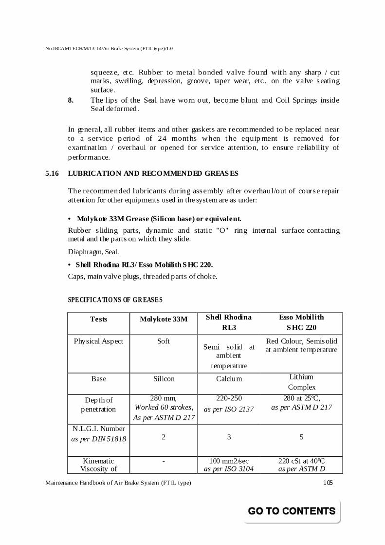
No.IRCAMTECH/M/13-14/Air Brake Sy stem (FTIL ty pe)/1.0
Maintenance Handbook o f Air Brake System (FTIL type) 105
squeeze, et c. Rubber to metal bonded valve found wit h any sharp / cut marks, swelling, depression, groove, taper wear, etc., on the valve seating surface.
8. The lips of the Seal have worn out, become blunt and Coil Springs inside Seal deformed.
In general, all rubber items and other gaskets are recommended to be replaced near to a service p eriod of 24 months when the equip ment is removed for examinat ion / overhaul or opened for service attention, to ensure reliability of performance.
5.16 LUBRICATION AND RECOMMENDED GREASES
The recommended lubricants during assembly aft er overhaul/out of course repair attention for other equipments used in the system are as under: • Molykote 33M Grease (Silicon base) or equivalent.
Rubber s liding parts, dynamic and static "O" ring internal surface contacting metal and the parts on which they slide.
Diaphragm, Seal.
• Shell Rhodina RL3/ Esso Mobilith SHC 220.
Caps, main valve plugs, threaded parts of choke.
SPECIFICA TIONS OF GR EASES
Tests Molykote 33M Shell Rhodina RL3
Esso Mobilith SHC 220
Physical Aspect Soft Semi solid at
ambient temperature
Red Colour, Semisolid at ambient temperature
Base Silicon Calcium Lithium Complex
Depth of penetration
280 mm, Worked 60 strokes, As per ASTM D 217
220-250
as per ISO 2137
280 at 25ºC, as per ASTM D 217
N.L.G.I. Number as per DIN 51818
2
3
5
Kinematic Viscosity of
- 100 mm2/sec as per ISO 3104
220 cSt at 40ºC as per ASTM D
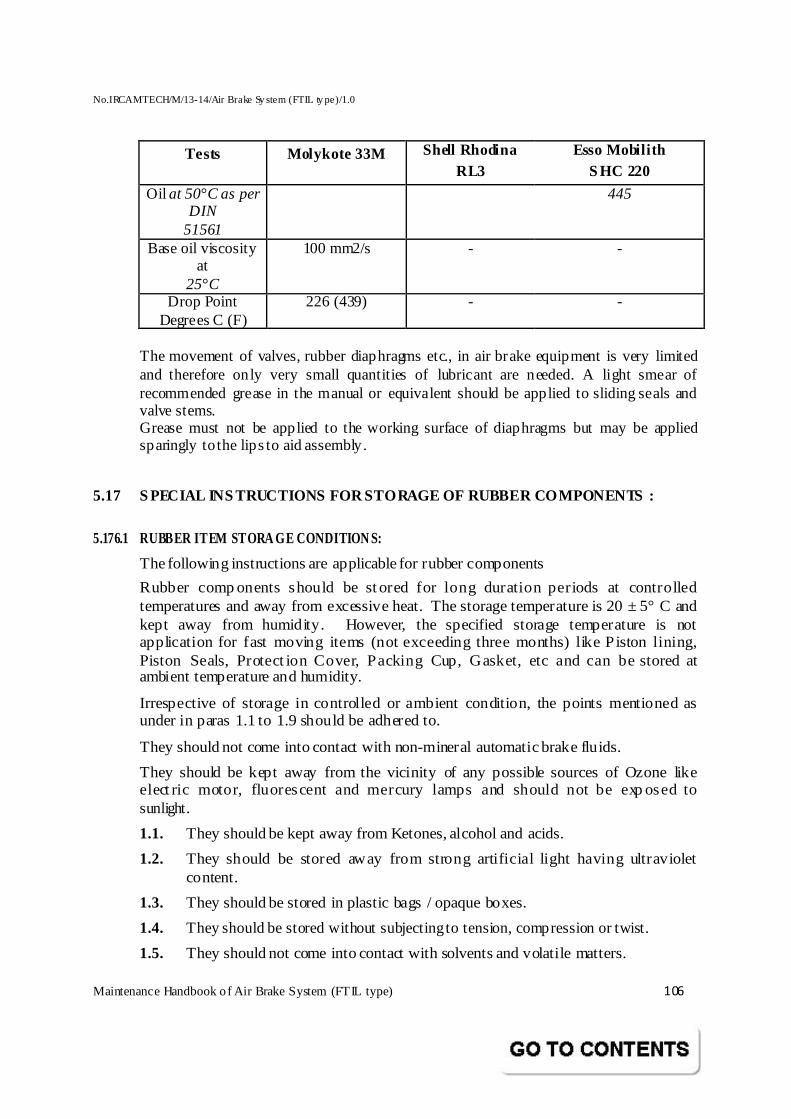
No.IRCAMTECH/M/13-14/Air Brake Sy stem (FTIL ty pe)/1.0
Maintenance Handbook o f Air Brake System (FTIL type) 106
Tests Molykote 33M Shell Rhodina RL3
Esso Mobilith S HC 220
Oil at 50°C as per DIN
51561
445
Base oil viscosity at
25°C
100 mm2/s - -
Drop Point Degrees C (F)
226 (439) - -
The movement of valves, rubber diaphragms etc., in air brake equipment is very limited and therefore only very small quantities of lubricant are needed. A light smear of recommended grease in the manual or equivalent should be applied to sliding seals and valve stems. Grease must not be applied to the working surface of diaphragms but may be applied sparingly to the lips to aid assembly.
5.17 S PECIAL INS TRUCTIONS FOR STORAGE OF RUBBER COMPONENTS :
5.176.1 RUBBER ITEM STORA GE CONDITION S:
The following instructions are applicable for rubber components
Rubber comp onents should be stored for long duration periods at controlled temperatures and away from excessive heat. The storage temperature is 20 ± 5° C and kept away from humidity. However, the specified storage temperature is not application for fast moving items (not exceeding three months) like Piston lining, Piston Seals, Protect ion Cover, Packing Cup, Gasket, etc and can be stored at ambient temperature and humidity.
Irrespective of storage in controlled or ambient condition, the points mentioned as under in paras 1.1 to 1.9 should be adhered to.
They should not come into contact with non-mineral automatic brake fluids.
They should be kept away from the vicinity of any possible sources of Ozone like elect ric motor, fluorescent and mercury lamps and should not be exp osed to sunlight.
1.1. They should be kept away from Ketones, alcohol and acids.
1.2. They should be stored away from strong artificial light having ultraviolet content.
1.3. They should be stored in plastic bags / opaque boxes.
1.4. They should be stored without subjecting to tension, compression or twist.
1.5. They should not come into contact with solvents and volatile matters.
No.IRCAMTECH/M/13-14/Air Brake Sy stem (FTIL ty pe)/1.0
Maintenance Handbook o f Air Brake System (FTIL type) 107
1.6. They should not come into contact with metals especially Copp er and Manganese.
1.7. They should not be cleaned with solvents like Tri-chloro-ethylene, Carbon tetra-chloride and Hydrocarbons. They can be cleaned with mild soapsuds and dried at room temperature.
1.8. They should not come into contact with metals especially Copper and Manganese.
1.9. They should not be cleaned with solvents like Tri-chloro-ethylene, Carbontetra-chloride and Hydrocarbons. They can be cleaned with mild soapsuds and dried at room temperature.
5.17.2 SHELF LIFE
The rubber components can be stored for a period of two years from the date of manufacture (indicated wherever possible on the component), before usage, if stored under controlled conditions.
Drawal from storage is to be on first-in-first-out basis in order to obtain the maximum service life.
Shelf life means strictly storage life beyond which the rubber properties will deteriorate if stored for longer period even in controlled conditions. However, if it is drawn from Stores during any part of the shelf life, it can serve satisfactorily much longer period than two years from the date of manufacture, as the component will be in dynamic conditions being subjected to flexib le forces inside the brake equipment.
Such dynamic life can extend to as long as 5 years, subjected to normal regular periodic maintenance and protected from damages due to external reasons such as abrasive particles in the air system, coagulation of grease due to water entry and sharp / rough edges / surfaces in the mating components.
5.17.3 EQUIPMENT
Brake equipment are sensitive and critical. Sufficient care is to be taken during handling, transportation, storage and installation, to avoid damages,
Performance deviation and reworking. C3W Distributor Valve assembly and Brake Cylinder need extra care.
Brake equipment are to be stored under covered roof to prevent entry and collection of dust / dirt / rain water.
Pipelines of brake system are to be kept with end protection caps under proper storage conditions till its fitment, to prevent collection of dust, moisture & rain.
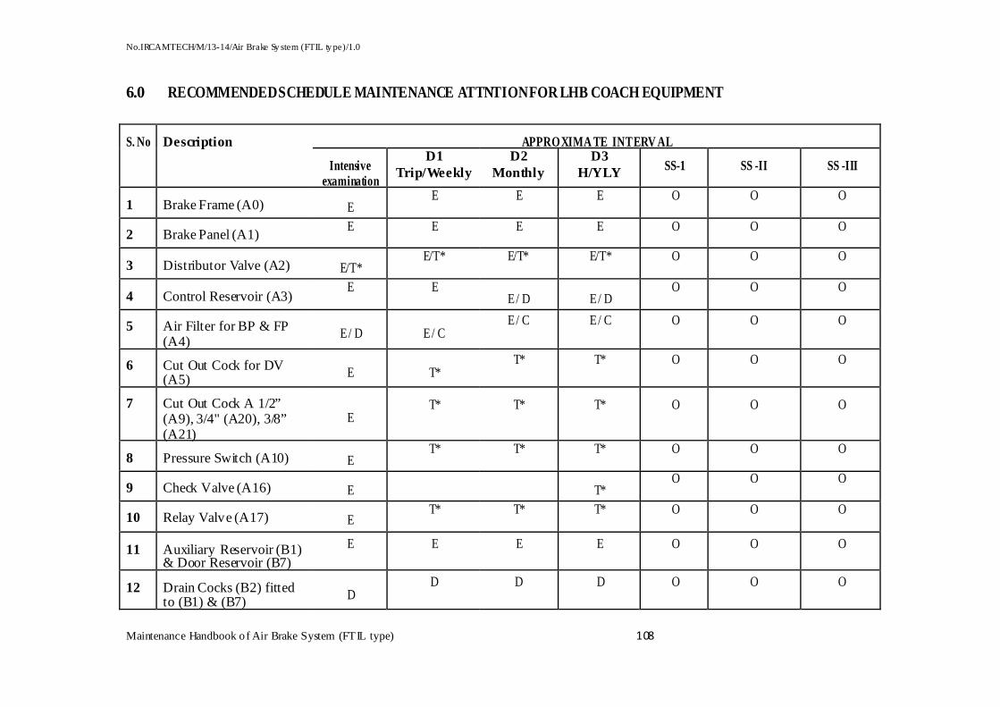
No.IRCAMTECH/M/13-14/Air Brake Sy stem (FTIL ty pe)/1.0
Maintenance Handbook o f Air Brake System (FTIL type) 108
6.0 RECOMMENDED SCHEDULE MAINTENANCE ATTNTION FOR LHB C OACH EQUIPMENT
APPROXIMA TE INTERV AL S. No Description
Intensive examination
D1 Trip/Weekly
D2 Monthly
D3 H/YLY SS-1 SS -II SS -III
1 Brake Frame (A0) E E E E O O O
2 Brake Panel (A1) E E E E O O O
3 Distributor Valve (A2) E/T* E/T* E/T* E/T* O O O
4 Control Reservoir (A3) E E
E / D E / D O O O
5 Air Filter for BP & FP (A4)
E / D E / C E / C E / C O O O
6 Cut Out Cock for DV (A5) E T*
T* T* O O O
7 Cut Out Cock A 1/2” (A9), 3/4" (A20), 3/8” (A21)
E T* T* T* O O O
8 Pressure Switch (A10) E T* T* T* O O O
9 Check Valve (A16) E T* O O O
10 Relay Valve (A17) E T* T* T* O O O
11 Auxiliary Reservoir (B1) & Door Reservoir (B7)
E E E E O O O
12 Drain Cocks (B2) fitted to (B1) & (B7) D
D D D O O O
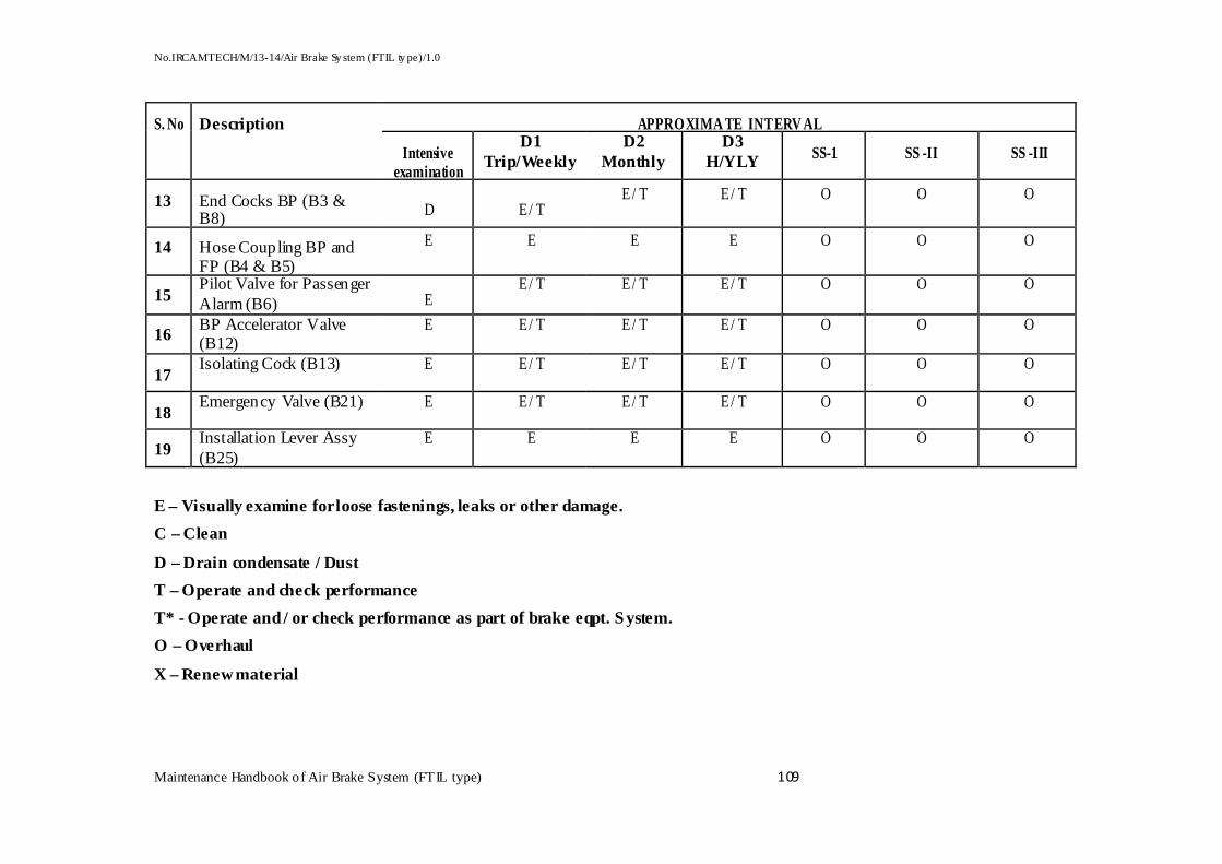
No.IRCAMTECH/M/13-14/Air Brake Sy stem (FTIL ty pe)/1.0
Maintenance Handbook o f Air Brake System (FTIL type) 109
APPROXIMA TE INTERV AL S. No Description
Intensive examination
D1 Trip/Weekly
D2 Monthly
D3 H/YLY SS-1 SS -II SS -III
13 End Cocks BP (B3 & B8) D E / T
E / T E / T O O O
14 Hose Coupling BP and FP (B4 & B5)
E E E E O O O
15 Pilot Valve for Passenger Alarm (B6) E
E / T E / T E / T O O O
16 BP Accelerator Valve (B12)
E E / T E / T E / T O O O
17 Isolating Cock (B13) E E / T E / T E / T O O O
18 Emergency Valve (B21) E E / T E / T E / T O O O
19 Installation Lever Assy (B25)
E E E E O O O
E – Visually examine for loose fastenings, leaks or other damage.
C – Clean
D – Drain condensate / Dust
T – Operate and check performance
T* - Operate and / or check performance as part of brake eqpt. System.
O – Overhaul
X – Renew material
No.IRCAMTECH/M/13-14/Air Brake Sy stem (FTIL ty pe)/1.0
Maintenance Handbook o f Air Brake System (FTIL type) 110
7.0 About the Brake Panel 1. The overall weight of the frame is reduced by about 80 kgs to facilitate easier handling
apart from offering lower accelerations during dynamic conditions, thus reducing the effect of vibration.
2. Header ports are in the same location as in existing with identification.
3. M aterial of frame is changed from Carbon steel to Stainless steel to avoid rusting during service.
4. The mounting dimensions of the frame including position of p iping have been retained to fit in the existing coaches also (This means no change is foreseen in the mounting or any other interface by the car builder).
5. The overall frame is provided with a protective mesh-guard to safeguard against the trackside ballast hits.
6. Adequate space is maintained on the panel for interchange ability of the DV with that of other approved manufacturers as per the specification
7. The positioning of the DV on the brake frame is made in such a way that the releaser lever arrangement can be attached even to this frame without any change.
8. Overall size of the Brake Panel is reduced from 765 x 472 x43 mm to 480 x 350 x 72 mm to facilitate easier handling during maintenance.
9. The compact size of the brake panel has permitted a simplified design of the protective cover instead of the current method of the sliding Door, Locking arrangement etc. as used in the current supplies. All the critical Isolating cocks are totally concealed from the free accessibility.
10. BP Isolating cock locking arrangement to avoid un-authorised operation.
11. The reservoirs (75 and 125 ltrs) are mounted at the top side of the frame to facilitate easy removal for servicing. The design adopted is positive holding principle.
If you have any suggestions and any specific comments, please write to us.
Contact person : Executive Director Postal address : Indian Railways, Centre for Advanced Maintenance Technology, Maharajpur, Gwalior. Pin code - 474 005 Phone : 0751- 2470803 Fax : 0751- 2470841
Email address : [email protected]
To upgrade maintenance technologies and methodologies and achieve improvement in productivity and performance of all Railway assets and man power which inter-alia would cover reliability, availability, utilisation and efficiency.
OUR OBJECTIVE