
LGH-50RVX-E, LGH-65RVX-E, LGH-80RVX-E LGH … · Cleaning and user maintenance shall not be made by...
22
Eng-1 English MODELS: Contents Safety precautions ............................................... 1 Outline drawings .................................................. 3 Standard installation examples............................ 4 Installation method .............................................. 4 Function settings ............................................... 13 Check points after installation work ................... 21 Trial operation.................................................... 21 Lossnay Energy Recovery Ventilator LGH-15RVX-E, LGH-25RVX-E, LGH-35RVX-E LGH-50RVX-E, LGH-65RVX-E, LGH-80RVX-E LGH-100RVX-E, LGH-150RVX-E, LGH-200RVX-E Installation Instructions (For use by dealer/contractor) Models LGH-15 to 100RVX-E Models LGH-150 and 200RVX-E This product needs to be installed properly in order to ensure maximum functionality as well as safety. Please make sure to read this installation manual before starting the installation. l Installation must be performed by a dealer or installation contractor. Please note that improper installation may cause malfunction or accident. “Operating Instructions” and this manual must be handed over to the customer after completing the installation. Safety precautions The following signs indicate that death or serious injury may be caused by failure to heed the precautions described below. WARNING Do not modify or disassemble. (It could cause fire, electric shock or injury.) Do not disassemble Prohibition of use in bath or shower room Connect the grounding wire. The instructions given must be followed. The instructions given must be followed. The Lossnay unit and remote controller should not be installed where it is highly humid, like a bathroom, or other wet place. (It could cause electric shock or power leakage.) Connect the product properly to ground. (Malfunctioning or power leaks can cause electrical shock.) Wiring work must be performed by qualified professionals, and be implemented safely and securely in accordance with the engineering standards and the extension wiring rules for electrical equipment. (Poor connection or improper wiring work could cause electric shock or fire.) Install a power supply isolator at the power supply side as per local electrical regulations. All supply circuits must be disconnected before obtaining access to the terminal devices. Use the specified cable size and connect the cables securely to prevent disconnection when they are pulled. (If there is a defect in the connection, there is a possibility of fire.) Select an adequate place for the opening to introduce outdoor air, where it will not intake the exhaust fumes like combustion gas, or others, and there is no risk of blockage. (Shortage of fresh air could put the room in a state of oxygen deficiency.) A duct made of steel must be installed with care not to be connected electrically with metal, wire, stainless steel plate, or others. (It could cause fire when power leakage occurs.) Use the specified power supply and voltage. (Use of incorrect power supply or voltage could cause fire or electric shock.) Select a place with sufficient strength and install the main unit securely. (It could cause injury if it falls.)
Transcript of LGH-50RVX-E, LGH-65RVX-E, LGH-80RVX-E LGH … · Cleaning and user maintenance shall not be made by...

Eng-1
English
MODELS:
ContentsSafety precautions ...............................................1Outline drawings ..................................................3Standard installation examples............................4Installation method ..............................................4Function settings ...............................................13Check points after installation work ...................21Trial operation ....................................................21
Lossnay Energy Recovery Ventilator
LGH-15RVX-E, LGH-25RVX-E, LGH-35RVX-ELGH-50RVX-E, LGH-65RVX-E, LGH-80RVX-E LGH-100RVX-E, LGH-150RVX-E, LGH-200RVX-EInstallation Instructions (For use by dealer/contractor)
Models LGH-15 to 100RVX-E Models LGH-150 and 200RVX-E
This product needs to be installed properly in order to ensure maximum functionality as well as safety.Please make sure to read this installation manual before starting the installation.l Installation must be performed by a dealer or installation contractor. Please note that improper installation may cause malfunction or accident.
“Operating Instructions” and this manual must be handed over to the customer after completing the installation.
Safety precautionsThe following signs indicate that death or serious injury may be caused by failure to heed the precautions described below.
WARNING
Do not modify or disassemble.(It could cause fire, electric shock or injury.)
Do not disassemble
Prohibition of use in bath or shower room
Connect the grounding wire.
The instructions given must be
followed.
The instructions given must be
followed.
The Lossnay unit and remote controller should not be installed where it is highly humid, like a bathroom, or other wet place.(It could cause electric shock or power leakage.)
Connect the product properly to ground. (Malfunctioning or power leaks can cause electrical shock.)
Wiring work must be performed by qualified professionals, and be implemented safely and securely in accordance with the engineering standards and the extension wiring rules for electrical equipment.(Poor connection or improper wiring work could cause electric shock or fire.)Install a power supply isolator at the power supply side as per local electrical regulations. All supply circuits must be disconnected before obtaining access to the terminal devices. Use the specified cable size and connect the cables securely to prevent disconnection when they are pulled. (If there is a defect in the connection, there is a possibility of fire.)Select an adequate place for the opening to introduce outdoor air, where it will not intake the exhaust fumes like combustion gas, or others, and there is no risk of blockage. (Shortage of fresh air could put the room in a state of oxygen deficiency.)A duct made of steel must be installed with care not to be connected electrically with metal, wire, stainless steel plate, or others.(It could cause fire when power leakage occurs.)
Use the specified power supply and voltage. (Use of incorrect power supply or voltage could cause fire or electric shock.)Select a place with sufficient strength and install the main unit securely.(It could cause injury if it falls.)
Eng-2
Prohibited
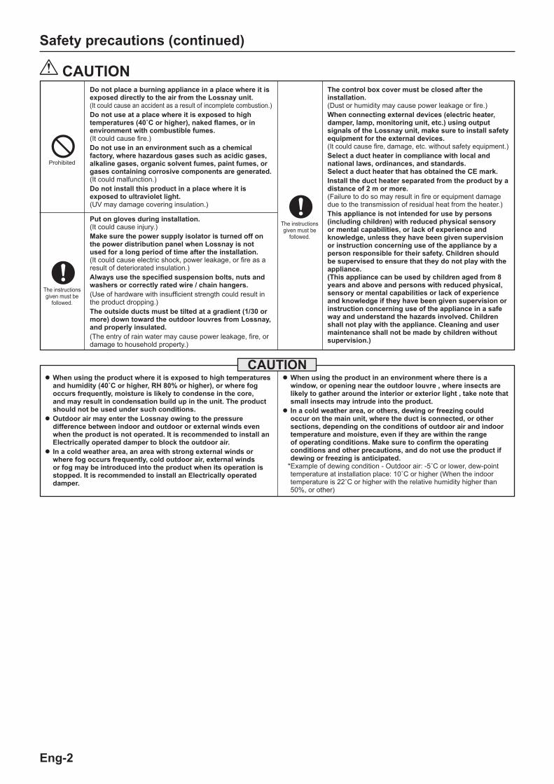
CAUTIONDo not place a burning appliance in a place where it is exposed directly to the air from the Lossnay unit.(It could cause an accident as a result of incomplete combustion.)Do not use at a place where it is exposed to high temperatures (40˚C or higher), naked flames, or in environment with combustible fumes. (It could cause fire.)Do not use in an environment such as a chemical factory, where hazardous gases such as acidic gases, alkaline gases, organic solvent fumes, paint fumes, or gases containing corrosive components are generated. (It could malfunction.)Do not install this product in a place where it is exposed to ultraviolet light. (UV may damage covering insulation.)
Put on gloves during installation. (It could cause injury.)Make sure the power supply isolator is turned off on the power distribution panel when Lossnay is not used for a long period of time after the installation. (It could cause electric shock, power leakage, or fire as a result of deteriorated insulation.)Always use the specified suspension bolts, nuts and washers or correctly rated wire / chain hangers. (Use of hardware with insufficient strength could result in the product dropping.)The outside ducts must be tilted at a gradient (1/30 or more) down toward the outdoor louvres from Lossnay, and properly insulated. (The entry of rain water may cause power leakage, fire, or damage to household property.)
The instructions given must be
followed.
The instructions given must be
followed.
Safety precautions (continued)
CAUTIONlWhen using the product where it is exposed to high temperatures
and humidity (40˚C or higher, RH 80% or higher), or where fog occurs frequently, moisture is likely to condense in the core, and may result in condensation build up in the unit. The product should not be used under such conditions.
lOutdoor air may enter the Lossnay owing to the pressure difference between indoor and outdoor or external winds even when the product is not operated. It is recommended to install an Electrically operated damper to block the outdoor air.
lIn a cold weather area, an area with strong external winds or where fog occurs frequently, cold outdoor air, external winds or fog may be introduced into the product when its operation is stopped. It is recommended to install an Electrically operated damper.
lWhen using the product in an environment where there is a window, or opening near the outdoor louvre , where insects are likely to gather around the interior or exterior light , take note that small insects may intrude into the product.
lIn a cold weather area, or others, dewing or freezing could occur on the main unit, where the duct is connected, or other sections, depending on the conditions of outdoor air and indoor temperature and moisture, even if they are within the range of operating conditions. Make sure to confirm the operating conditions and other precautions, and do not use the product if dewing or freezing is anticipated.
*Example of dewing condition - Outdoor air: -5˚C or lower, dew-point temperature at installation place: 10˚C or higher (When the indoor temperature is 22˚C or higher with the relative humidity higher than 50%, or other)
The control box cover must be closed after the installation. (Dust or humidity may cause power leakage or fire.) When connecting external devices (electric heater, damper, lamp, monitoring unit, etc.) using output signals of the Lossnay unit, make sure to install safety equipment for the external devices.(It could cause fire, damage, etc. without safety equipment.)Select a duct heater in compliance with local and national laws, ordinances, and standards. Select a duct heater that has obtained the CE mark.Install the duct heater separated from the product by a distance of 2 m or more. (Failure to do so may result in fire or equipment damage due to the transmission of residual heat from the heater.)This appliance is not intended for use by persons (including children) with reduced physical sensory or mental capabilities, or lack of experience and knowledge, unless they have been given supervision or instruction concerning use of the appliance by a person responsible for their safety. Children should be supervised to ensure that they do not play with the appliance. (This appliance can be used by children aged from 8 years and above and persons with reduced physical, sensory or mental capabilities or lack of experience and knowledge if they have been given supervision or instruction concerning use of the appliance in a safe way and understand the hazards involved. Children shall not play with the appliance. Cleaning and user maintenance shall not be made by children without supervision.)
Eng-3
English
1010
C DBA
1144 7944
700
4027
0
ø242
ø258
404808
26
110
ø258
ø242
270
4040
N
JJ A
F
C
F
KL
B E
D
M
20
M
φ Gφ
H
N
115
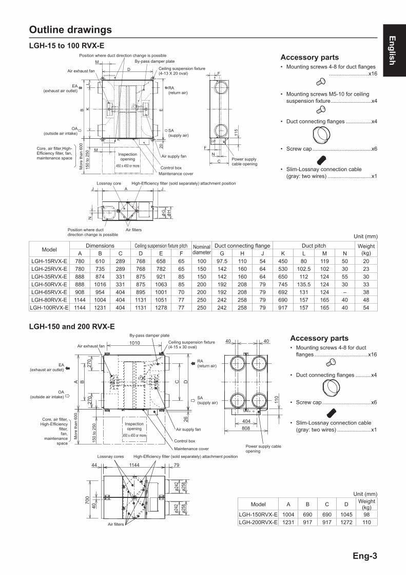
Outline drawings
Accessory parts• Mounting screws 4-8 for duct flanges ..........................x16
• Mounting screws M5-10 for ceiling suspension fixture ...........................x4
• Duct connecting flanges .................x4
• Screw cap .......................................x6
• Slim-Lossnay connection cable (gray: two wires) .............................x1
ModelDimensions Ceiling suspension fixture pitch Nominal
diameterDuct connecting flange Duct pitch Weight
(kg)A B C D E F G H J K L M NLGH-15RVX-E 780 610 289 768 658 65 100 97.5 110 54 450 80 119 50 20LGH-25RVX-E 780 735 289 768 782 65 150 142 160 64 530 102.5 102 30 23LGH-35RVX-E 888 874 331 875 921 85 150 142 160 64 650 112 124 55 30LGH-50RVX-E 888 1016 331 875 1063 85 200 192 208 79 745 135.5 124 30 33LGH-65RVX-E 908 954 404 895 1001 70 200 192 208 79 692 131 124 – 38LGH-80RVX-E 1144 1004 404 1131 1051 77 250 242 258 79 690 157 165 40 48LGH-100RVX-E 1144 1231 404 1131 1278 77 250 242 258 79 917 157 165 40 54
Unit (mm)
LGH-150 and 200 RVX-E
Model A B C D Weight (kg)
LGH-150RVX-E 1004 690 690 1045 98LGH-200RVX-E 1231 917 917 1272 110
Unit (mm)
Accessory parts• Mounting screws 4-8 for duct
flanges ...................................x16
• Duct connecting flanges ..........x4
• Screw cap ................................x6
• Slim-Lossnay connection cable (gray: two wires) ......................x1
Ceiling suspension fixture (4-15 x 30 oval)
SA (supply air)
RA (return air)EA
(exhaust air outlet)
OA (outside air intake)
Core, air filter, High-Efficiency
filter, fan,
maintenance space
Lossnay cores
Air exhaust fan
By-pass damper plate
Air supply fan
Maintenance cover
Inspection opening
450 x 450 or more
Air filters
Mor
e th
an 6
00
EA (exhaust air outlet)
Air exhaust fan
OA (outside air intake)
Core, air filter,High-Efficiency filter, fan, maintenance space
Mor
e th
an 6
00
Position where duct direction change is possible
Air filters
Lossnay core
Inspection opening
450 x 450 or more Control boxMaintenance cover
Air supply fan
RA (return air)
SA (supply air)
By-pass damper platePosition where duct direction change is possible
High-Efficiency filter (sold separately) attachment position
Ceiling suspension fixture (4-13 X 20 oval)
Power supply cable opening
Power supply cableopening
Control box
High-Efficiency filter (sold separately) attachment position
LGH-15 to 100 RVX-E
150
to 2
5015
0 to
250

Eng-4
Standard installation examples
Model DistanceLGH-15 to 65RVX-E 1 m or more
LGH-80 and 100RVX-E 2.5 m or moreLGH-150 and 200RVX-E 3 m or more
• The parts can also be installed upside down. Remove the maintenance cover, rotate the parts
by 180°, and re-install.
• Duct length
Installation method
EA (exhaust air outlet)
Inspection opening (450x450 or more)
SA (supply air)
Supply air grille(not included)
Deep hood(to prevent rain water from seeping in)
Downward gradient of duct: 1/30 or more (toward wall side) and provision of distance in table below (to prevent rain water from seeping in)
DuctAnchor bolt (to be provided by user)
RA (return air)
Return air grille(not included)
OA (outside air intake)
Lossnay unit
Duct connecting flange (Accessory parts)
Mounting screw(size: 4-8)(Accessory parts)
Mounting screw (size:4-8)(Accessory parts)
Duct connecting flange (Accessory parts)
Models LGH-15 to 100RVX-E
Models LGH-150 and 200RVX-E
Lossnay unit
Return air grille(not Included)
Maintenance space
Inspection opening
EA (exhaust air outlet)
OA (outside air intake) Supply air grille(not included)
* Except the 150 and 200 RVX-E.
Remote controller(optional parts)
EA(exhaust air outlet)
OA(outside air intake)
* It can be installed by inverting the top and the bottom.
After installing the duct connecting flange, remove the maintenance cover. Turn the cover by 180˚, and then reinstall it.
Maintenance space
Lossnay unit
Inspection opening
EA(exhaust air outlet)
OA(outside air intake)
EA(exhaust air outlet)OA(outside air intake)
Lossnay unit
Electrically operated damper(Protection against the intrusion of cold air while Lossnay is stopped in winter)(To be provided by the customer)
• In a region where there is risk of freezing in winter, it is recommended to install an Electrically operated damper, or the like, in order to prevent the intrusion of (cold) outdoor air while Lossnay is stopped.
CAUTION• Do not install Lossnay unit vertically or on an incline.
Installing the Lossnay unit
1. Attaching the duct connecting flanges Use the supplied screws (size:4-8) to secure the duct connecting
flanges to the Lossnay unit.
CAUTION• Before attaching the duct connecting flanges, check that no
foreign matter (scraps of paper, vinyl, etc.) has found its way inside to Lossnay unit.
• Attach the duct connecting flanges with the packing at the SA and RA sides.
2. Securing the ceiling suspension fixturesModels LGH-15 to 100RVX-E(1) Loosen the screws for the ceiling suspension fixtures. (2) Rotate the ceiling suspension fixtures 90° centered around the
loosened screws to make them horizontal. (3) Firmly tighten and secure the ceiling suspension fixtures to the
product with the loosened screws and the included mounting screws (M5-10).
* The ceiling suspension fixtures are folded and secured to the unit when shipped from the factory.
Loosen
Mounting screw(size: 5-10)(Accessory parts)

Eng-5
English
Installation method (continued)
Models LGH-15 to 100RVX-E
Models LGH-150 and 200RVX-ETaping Duct
Heat-insulating material
Duct connecting flange
Duct
Taping
Aluminium tape
Duct connecting flange
Outdoor duct
Heat-insulating material
Lossnay unit
Aluminium tape
Duct connecting flange
Outdoor duct
Heat-insulating material
Lossnay unit
• Extremely sharp bends
• Multiple bends • Bends right next to the outlet
• Extreme reduction in the diameter of the connected ducts
5. Connecting the ducts(1) Fasten the duct securely to the duct connecting flange, and
wrap aluminium tape (field supply) around the joints so that there is no air leakage.
(2) Suspend the ducts from the ceiling so that their weight will not be applied to the Lossnay unit.
(3) The two outdoor ducts must be covered with heat-insulating material in order to prevent condensation from forming.
CAUTION• When on-site commissioning is planned, a straight duct
length more than 10xD (D=duct diameter) from the source of turbulence like bends, contractions and dampers etc, to the measurement point is recommended for correct measurement.In the United Kingdam, on-site measurment should therefore be measured in accordance with BSRIA guideline (Commissioning Air System. Application procedures for buildings AG3/89.3(2001))
• Before attaching the ducts, check that no (debris or any other) foreign matter (scraps of paper, vinyl, etc.) has found its way inside the ducts.
• Do not touch the damper plate inside Lossnay unit when connecting the ducts.
• If it is expected that the ambient temperature around the place where the Lossnay unit is installed will be high during the summer air conditioning season, it is recommended that the indoor duct work be covered with insulation material.
Do not carry out the following types of duct construction. (Doing so could cause a drop in the air volume and generate abnormal noises.)
Anchor bolt Ceiling suspension fixture
Washer Nut
Models LGH-15 to 100RVX-E
Models LGH-150 and 200RVX-E
Ceiling suspension fixture
Anchor bolt (M10 or M12)
Washer
Washer
Nut
Nut
4. Mounting Lossnay unit(1) Hang the ceiling suspension fixtures on the anchor bolts and
adjust in such a way that Lossnay unit is level.(2) Tighten up securely using double nuts.
CAUTION• When suspending Lossnay unit from the ceiling, do not handle
it in such a way that force will be applied to the control box.• Install the anchor bolts to ensure the product's weight or
earthquake load. (Correctly rated wire/chain may also be used)
3. Preparing the anchor bolts Mount the washers (outer diameter of >21 mm for M10, >24 mm
for M12) and nuts onto the pre-recessed anchor bolts (M10 or M12), as shown in the figure below.
[When using (customer-prepared) vibration isolation rubber] When using (customer-prepared) vibration isolation rubber, there
is a possibility of this causing a decrease in strength, so we recommend the following type of construction.
Anchor bolt (M10 or M12)
Anchor bolt (M10 or M12)
Nut
Nut
Washer
Washer
Nut
Nut
Vibration isolation rubber
CAUTIONUSE TWO NUTS
CAUTIONUSE TWO NUTS
Room Side
Outdoor Side
Room Side
Outdoor Side
Eng-6
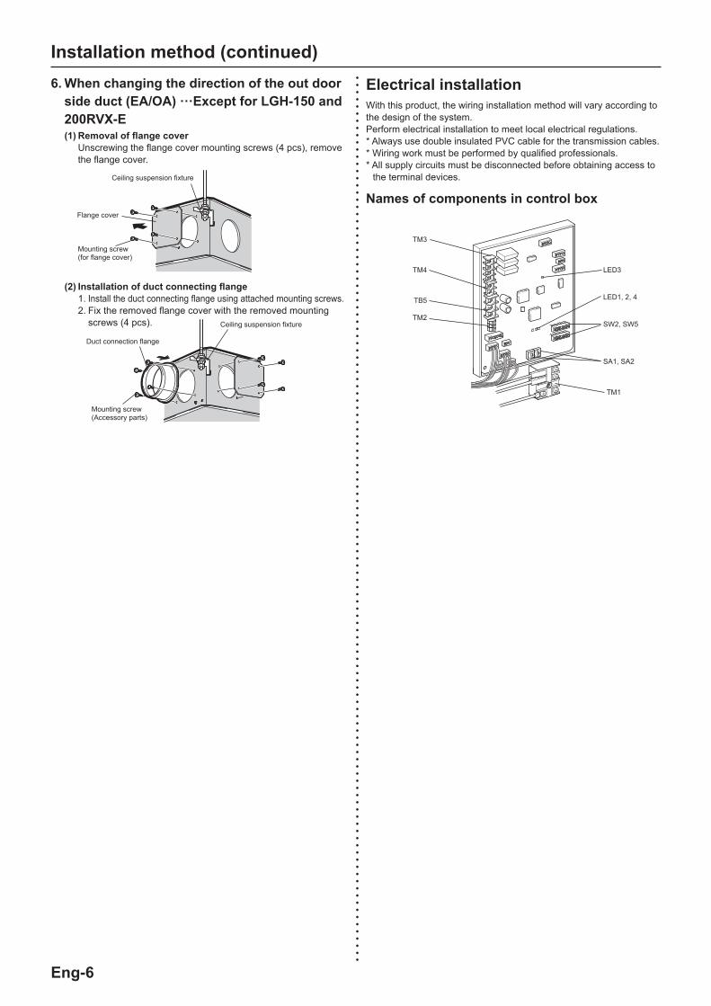
Flange cover
(2) Installation of duct connecting flange 1. Install the duct connecting flange using attached mounting screws. 2. Fix the removed flange cover with the removed mounting
screws (4 pcs).
Mounting screw (for flange cover)
Mounting screw(Accessory parts)
Duct connection flange
Ceiling suspension fixture
Ceiling suspension fixture
6. When changing the direction of the out door side duct (EA/OA) ···Except for LGH-150 and 200RVX-E(1) Removal of flange cover Unscrewing the flange cover mounting screws (4 pcs), remove
the flange cover.
Installation method (continued)
Names of components in control box
Electrical installationWith this product, the wiring installation method will vary according to the design of the system.Perform electrical installation to meet local electrical regulations.* Always use double insulated PVC cable for the transmission cables.* Wiring work must be performed by qualified professionals.* All supply circuits must be disconnected before obtaining access to
the terminal devices.
TM1
LED3
LED1, 2, 4
SW2, SW5
SA1, SA2
TM3
TB5
TM2
TM4

Eng-7
English
7
8
9
10
S
A
B
1
2
1
2
N
L
N
PE
L
M1
M2
GM CN7
CN118
CN119
CN10
CN9LED6
TAB3,4
TAB2TAB5 TAB1
TH1(OA)TH2(RA)
TM1
CN19
CN18
CN22CN5
SA2SA1
SW5
SW2
3
TM2
TB5
TM4
TM3
PZ-61DR-E
CN26
CN32
CN17
LED3
LED4
LED2LED1
Installation method (continued)Wire connection diagram ----- Model LGH-15 to 100 RVX-E* TM1, TM2, TM3, TM4, TB5 shown in dotted lines are field work.* Be sure to connect the ground wire.* A power supply isolator must be installed.* Always use an isolator for the main switch power connection.
Definition of symbolsM1: Motor for exhaust fanM2: Motor for supply fanGM: Motor for By-pass damperTH1: Thermistor for outside airTH2: Thermistor for return airSW2,5: Switch (Function selection)TM1: Terminal block (Power supply)TM2: Terminal block (External control input)TM3: Terminal block (Monitor output)TM4: Terminal block (Transmission cable)TB5: Terminal block (M-NET Transmission cable)TAB1, TAB2, (TAB5): Connector (Power supply)TAB3,TAB4: Connector (Reactor)
X13: Relay contactX14: Relay contactX15: Relay contactCN5: Connector (Thermistor RA)CN7: Connector (Motor for By-pass damper)CN9: Connector (Fan motor)CN10: Connector (Fan motor)CN17: Connector (Fan speed 1/2/3/4)CN18: Connector CN118: ConnectorCN19: Connector CN119: ConnectorCN22: Connector (Thermistor OA)
CN26: Connector (By-pass, 0 - 10 VDC Fan speed control)CN32: Connector (Remote control selection)SA1: Address setting rotary switch (10 digit)SA2: Address setting rotary switch (1 digit)LED1 to LED3: Inspection indicator lampLED4, LED6: Power supply indicator lampSYMBOL : Terminal block : Connector on PCB
SUPPLY FAN MOTOR
REACTOR
EXHAUST FAN MOTOR
By-pass monitor or Pre-heater signal output (*1)
Malfunction monitor output (*1)
Exhaust or Supply fan monitor output (*1)
12V or 24V DCMr .Slim (non-polar)Uncharged
A-contact
M-NET-transmission cable
2nd remote controller (Max. 2 controllers)2nd Lossnay unit (Max. 15 units)
(*1)MAX 240 VAC 1 A MIN 220 VAC 100 mA 24 VDC 1 A 5 VDC 100 mA
Isolator (Field supply)
POWER SUPPLY 220-240 V / 50Hz 220 V / 60Hz
LINE FILTER
Shielded Wire
COM
Lower Printed Circuit Board
Upper Printed Circuit Board
X15 X14 X13

Eng-8
7
8
9
10
S
A
B
1
2
1
2
N
L
N
PE
L
M1
M2
GMCN7
CN118
CN119CN10
CN9TAB3,4
TAB2
TAB1
TH1(OA)
TH2(RA)
TM1
CN19
CN18
CN22CN5
SA2SA1SW5
SW2
3
TM2
TB5
TM4
X15 X14 X13
TM3
PZ-61DR-E
CN26
CN32
CN17
TAB5
M1
M2
GM CN7
CN10
CN9TAB3,4
TAB2 TAB1
CN121
CN21
LED6
LED6
LED3
LED4
LED2LED1
Installation method (continued)Wire connection diagram ----- Models LGH-150 and 200 RVX-E* TM1, TM2, TM3, TM4, TB5 shown in dotted lines are field work.* Be sure to connect the ground wire.* A power supply isolator must be installed.* Always use an isolator for the main switch power connection.
SUPPLY FAN MOTOR
EXHAUST FAN MOTOR
SUPPLY FAN MOTOR
EXHAUST FAN MOTOR
REACTOR
REACTOR
By-pass monitor or Pre-heater signal output (*1)
Malfunction monitor output (*1)
Exhaust or Supply fan monitor output (*1)
M-NET-transmission cable
2nd remote controller (Max. 2 controllers)2nd Lossnay unit (Max. 15 units)
(*1)MAX 240 VAC 1 A MIN 220 VAC 100 mA 24 VDC 1 A 5 VDC 100 mA
Isolator (Field supply)
Shielded Wire
COM
Lower Printed Circuit Board 2
Lower Printed Circuit Board 1
Upper Printed Circuit Board
LINE FILTER
Definition of symbolsM1: Motor for exhaust fanM2: Motor for supply fanGM: Motor for By-pass damperTH1: Thermistor for outside airTH2: Thermistor for return airSW2, 5: Switch (Function selection)TM1: Terminal block (Power supply)TM2: Terminal block (External control input)TM3: Terminal block (Monitor output)TM4: Terminal block (Transmission cable)TB5: Terminal block (M-NET Transmission cable)TAB1, TAB2, TAB5: Connector (Power supply)TAB3, TAB4: Connector (Reactor)
X13: Relay contactX14: Relay contactX15: Relay contactCN5: Connector (Thermistor RA)CN7: Connector (Motor for By-pass damper)CN9: Connector (Fan motor)CN10: Connector (Fan motor)CN17: Connector (Fan speed 1/2/3/4)CN18: Connector CN118: Connector CN19: Connector CN119: Connector
CN21: Connector CN121: ConnectorCN22: Connector (Thermistor OA)CN26: Connector (By-pass, 0 - 10 VDC Fan speed control)CN32: Connector (Remote control selection)SA1: Address setting rotary switch (10 digit)SA2: Address setting rotary switch (1 digit)LED1 to LED3: Inspection indicator lampLED4, LED6: Power supply indicator lampSYMBOL : Terminal block : Connector on PCB
12V or 24V DCMr .Slim (non-polar)Uncharged
A-contact
POWER SUPPLY 220-240 V / 50Hz 220 V / 60Hz

Eng-9
English
Black screws
LGH-150 and 200 RVX-EControl box cover
Control box cover
LGH-15 to 100 RVX-E
Black screws
Installation method (continued)
Connecting the power supply cable1. Remove the black screws and the control box cover
Power supply cable
Power supply cable
Cord clip
Insert the cutting
TM1
Bush
PG connector
Ground wire
Transmission cable
3. Connecting the power supply cable and transmission cable
Pass the Power supply cable through the bush* and connect to the TM1 terminal block using the round terminals. Connect the ground wire to the ground terminal and secure tightening the bush. (* Use an item that can firmly secure the cable such as a PG connector.)
2. Attach the screw cap.
CAUTION• After installing the Lossnay unit, attach the supplied screw
caps to the screws at the bottom of the unit.
CAUTION• Always separate the power supply cable and transmission
cable by 5 cm or more to prevent malfunctioning of the unit. • If the length of the stripped Power supply cable is too long,
the conductors may touch and short out.• Power supply cable size : 1.5 mm2 (ø9)or more.
Models LGH-15 to 100RVX-E Models LGH-150 and 200RVX-E
(1) Tighten the ground wire and transmission cables to the terminal block.
(2) Secure the transmission cables using the cord clips.Upon completion of the wiring connections, replace the control box cover.
The following system configuration can be created. Connect the necessary parts.1 When connecting with remote controller (PZ-61DR-E).2 When interlocked with indoor unit of air conditioner or other
external device including other manufactures.3 When operating multiple Lossnay units.4 By-pass monitor or Pre-heater signal output.5 Malfunction monitor output.6 Operation monitor output7 When switching fan speed externally (when a sensor or other
device is connected).8 When switching By-pass externally.9 To change fan speed by 0 - 10 VDC input10 When using the remote/local switching and the ON/OFF input
(level signal)11 When connecting to the City Multi or Mitsubishi Electric Air-
Conditioner Network System (MELANS).12 To start/stop Lossnay stand-alone operation without using the
remote control
CAUTION• When connecting external devices (electric heater, damper,
lamp, monitoring unit, etc.) using output signals of the Lossnay unit, make sure to install safety equipment for the external devices.
(It could cause fire, damage, etc. without safety equipment.)
Power supplyUp to two remote controllers
Lossnay
When connecting with remote controller (PZ-61DR-E)1
21
Remote controller input terminal
Transmission cables
* When controlling Lossnay units with MELANS, connect wires according to 11 .
Securely connect the transmission cable from the remote controller to 1 and 2 of the input terminal block (TM4). (No polarity)
Wire type: two-core sheathed cable Wire diameter: 0.3 mm2
• If there are two remote controllers, connect them in the same way.• Keep the overall length of the transmission cable between
Lossnay and the remote controller within 200 m. Note
• Do not tighten screws of terminal block with a torque larger than 0.5 Nm. It could damage the PCB.
• Take care not to connect the power supply cable or M-NET transmission cable.
• Number of transmission cables which can be connected to single input terminal is up to 4 wires.
• Single wires such as PVC wires cannot be connected.
Screw
Screw cap
Screw
Screw cap

Eng-10
When interlocked with indoor unit of air conditioner or other external device including other manufactures2
CAUTION• The connection may vary according to the output signal type
of the external unit.• Don’t tighten screws of terminal block with a torque larger
than 0.5 Nm. It could damage the PCB.
Installation method (continued)
When using Mitsubishi Mr. Slim air conditioner with MA Remote controller
Confirm that the pulse input switch (SW2-2) is set to “OFF”. (Factory setting is “OFF”.) (Refer to function settings No. 28 ) Connect the interlocking cable connector side to CN2L on the
circuit board for the Mr. Slim indoor unit, then connect the lead wire side to the 1 and 2 of the input terminal block (TM2) for the Lossnay external controller input. (No polarity)• Always separate the power supply cable and the Slim-Lossnay
connection cable by 5 cm or more to prevent the unit from malfunctioning.
• The Slim-Lossnay connection cable is 100 mm long. When wiring, extend it as far as necessary.
Lossnay external control input (TM2)
Slim-Lossnay connection cable(Accessory parts)
Printed circuit board
Maximum 500 m
CN2L
Mr. Slim (Indoor unit)
Operating switch for external device
Power supply
External device
Lossnay
Power supply
Note• The Lossnay remote controller (PZ-61DR-E) cannot be used
with this system.• Use MA remote controller of Mr. Slim for switching Lossnay
ON/OFF or the fan speed.• The ventilation mode is “automatic ventilation”.• Ensure that all connections are secure and that the
appropriate insulation is provided. Use extension cable sheathed PVC cable or cable 0.5 mm2
to 1.5 mm2.
When the external device has a charged operating signal of 12 VDC or 24 VDC
[SW2-2] setting vary depending on the types of output signal of external device.
• Move the pulse input switch [SW2-2] to the ON position. (Refer to function settings No. 28 )• When interlocking with a pulse output device, a pulse width is
at least 200 m sec. to turn Lossnay ON, and 10 sec. interval is necessary to next output.
• The wiring should be the following picture.
Lossnay external control input (TM2)
0.5 mm2 to 1.5 mm2 sheathed PVC cable
External device
12 or 24 VDC
Overall connection extension length
(Follow the operation manual for the external equipment.)
Lossnay external control input (TM2)
0.5 mm2 to 1.5 mm2 sheathed PVC cable
External device
Uncharge a-contact
Maximum 500 m
When the external device has an uncharged a-contact signal• The wiring should be the following picture.
CAUTION• If an optocoupler or any other type of polar coupler is used at
the uncharged a-contact, connect the positive side to 3 and the negative side to 1.
When operating multiple Lossnay units31) Connect from Lossnay Unit 1 to Lossnay Unit 2, and from Unit 2 to
Unit 3 and so on up to a maximum of 15 units using a transmission cable.
Wire type: two-core sheathed cable Wire diameter: 0.3 mm2
2) When it is interlocked with an external device, turn ON the setting switch (SW5-10) of main Lossnay where the external signal is input.
Lossnay Remote controller (PZ-61DR-E)
Lossnay
MAX 15 units
Power supply
Power supply
Power supply
Lossnay
Connect to remote controller (PZ-61DR-E)
Connect to third Lossnay
21
21
Transmission cable
First Lossnay
Second Lossnay
TM4
TM4
CAUTION Don’t tighten screws of terminal block with a torque larger
than 0.5 Nm. It could damage the PCB.
Note• Up to four transmission cables can be connected to one
input terminal. • Single wires such as PVC wires cannot be connected. • Only one unit can be set as main Lossnay. The operating
signal and pulse signal of the external device can be connected to main Lossnay only.
• When the external signal is not input, main-unit setting is not required even for operation of multiple units.
• Connect the power supply cable to each Lossnay unit.
TM2
1 2SW5 ON
OFF
3 4 5 6 7 8 9 10
ON

Eng-11
English
Installation method (continued)
By-pass monitor or Pre-heater signal can be selected at SW5-6.(Refer to function settings No. 58 )Always check that it is the intended setting.
CAUTION• Select a duct heater in compliance with local and national
laws, ordinances, and standards. Select a duct heater that has obtained the CE mark.• Always select a heater that is equipped with a non-self-
resetting safety device. Do not directly supply power from the Lossnay unit to the
duct heater. (Doing so could cause fire.)• Install a circuit breaker for the duct heater in compliance with
all applicable laws, ordinances, and standards.• Install the duct heater separated from the product by a
distance of 2 m or more. (Failure to do so may result in equipment damage due to the
transmission of residual heat from the heater.)• When using a heater without a temperature control function,
select a heater with a capacity that is matched to the air volume.
• Do not use the heater outside the set air volume. (If the heater’s capacity is too larger, this may result in the
heater frequently turning ON/OFF.) (If the heater’s capacity is too small, this may result an
inability to heat.)• Ensure that the duct heater and Lossnay are wired and that
the Lossnay function settings have been configured, and then always check operation by trial operation.
• For the duct heater output, see function setting SW5-6.
By-pass monitor or Pre-heater signal output.
9
8
7
10
9
8
7
10
By-pass monitor SW5-6 OFF
Pre-heater output SW5-6 ON
Power Supply
Relay
Pre-heater
2 m or more
Power Supply for heater Power Supply
for relay
TM3
TM3
4
Max 240 VAC, 1 A 24 VDC, 1 AMin 220 VAC, 100 mA 5 VDC, 100 mA
Max 240 VAC, 1 A 24 VDC, 1 AMin 220 VAC, 100 mA 5 VDC, 100 mA
By-pass operation indicator
9
8
7
10
Operation monitor output can be selected to sympathize with exhaust fan or supply fan at SW 5-2.SW5-2 OFF: Exhaust fan operation monitor outputSW5-2 ON: Supply fan operation monitor output(Refer to function settings No. 57 )Always check that it is the intended setting.
Operation indicator
Power Supply
Operation monitor output6
Malfunction monitor output.
9
8
7
10
Relay
2 m or more
Power Supply for heater
Power Supply for relay
Power Supply
TM3
TM3
TM3
5
Max 240 VAC, 1 A 24 VDC, 1 AMin 220 VAC, 100 mA 5 VDC, 100 mA
Max 240 VAC, 1 A 24 VDC, 1 AMin 220 VAC, 100 mA 5 VDC, 100 mA
Max 240 VAC, 1 A 24 VDC, 1 AMin 220 VAC, 100 mA 5 VDC, 100 mA
Malfunction indicator
9
8
7
10
SW1 CN17
When switching fan speed externally(when a sensor or other equipment is connected)7
Using a field supply sensor, etc., make connection by inserting the optional remote display adaptor (PAC-SA88HA-E) in the connector CN17 (Red) as shown by the figure.Lossnay will operate the fan speed following the table below, regardless of the remote controller setting.
CN17 (Red) Fan speed1-2 (Brown-Red) 41-3 (Brown-Orange) 31-4 (Brown-Yellow) 21-5 (Brown-Green) 1
nExample “Fan speed 4”
Use this in such a way that it ventilates at low fan speed normally, and when the external sensor detects contamination of indoor air, it changes to high fan speed operation.
Field supply sensor, etc. Remote display adaptor (Optional) PAC-SA88HA-E
Brown 1
Red 2Orange 3Yellow 4Green 5
Not used. Insulate completely.Max wiring length 10 m
Lossnaycontrol board
Fan speed selection
X13
SAOA
Lossnay
Lossnay
X13
X14
X15
X15
SAOA
To use operation monitor output for a supply after-heater, turn SW2-8 ON, and use the supply fan operation monitor output with delayed operation. (Refer to function settings No. 57 )For the heater, observe the cautions listed in 4 .
Eng-12
SW1
CN26
CN26
Installation method (continued)
SBATB5
M-NET transmission cable
Shielded wire M-NET transmission cable input terminal block
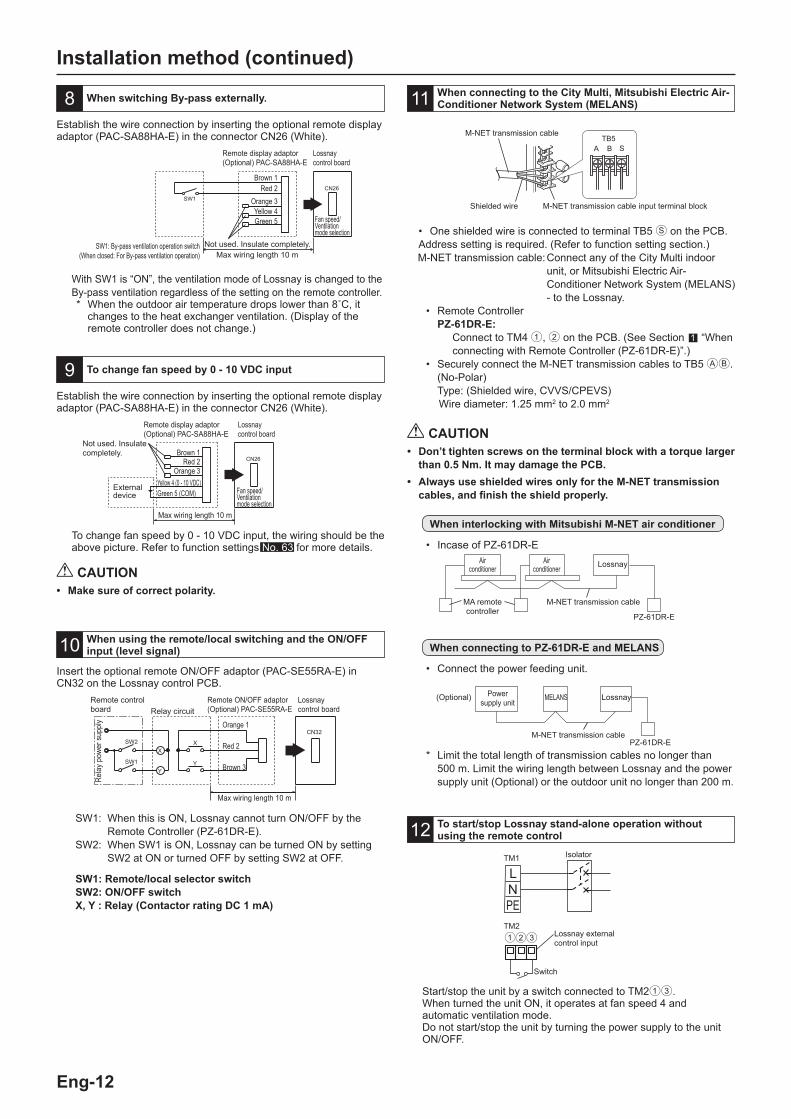
When switching By-pass externally.
To change fan speed by 0 - 10 VDC input
8
9
Establish the wire connection by inserting the optional remote display adaptor (PAC-SA88HA-E) in the connector CN26 (White).
Establish the wire connection by inserting the optional remote display adaptor (PAC-SA88HA-E) in the connector CN26 (White).
To change fan speed by 0 - 10 VDC input, the wiring should be the above picture. Refer to function settings No. 63 for more details.
With SW1 is “ON”, the ventilation mode of Lossnay is changed to the By-pass ventilation regardless of the setting on the remote controller.* When the outdoor air temperature drops lower than 8˚C, it
changes to the heat exchanger ventilation. (Display of the remote controller does not change.)
When using the remote/local switching and the ON/OFF input (level signal)10
Insert the optional remote ON/OFF adaptor (PAC-SE55RA-E) in CN32 on the Lossnay control PCB.
CN32
SW1
SW2
Y
X
Y
X
SW1: When this is ON, Lossnay cannot turn ON/OFF by the Remote Controller (PZ-61DR-E).
SW2: When SW1 is ON, Lossnay can be turned ON by setting SW2 at ON or turned OFF by setting SW2 at OFF.
SW1: Remote/local selector switchSW2: ON/OFF switchX, Y : Relay (Contactor rating DC 1 mA)
When connecting to the City Multi, Mitsubishi Electric Air-Conditioner Network System (MELANS)11
SW1: By-pass ventilation operation switch(When closed: For By-pass ventilation operation)
Remote display adaptor (Optional) PAC-SA88HA-E
Remote display adaptor (Optional) PAC-SA88HA-E
Brown 1Red 2
Orange 3Yellow 4Green 5
Yellow 4 (0 - 10 VDC)Green 5 (COM)
Lossnaycontrol board
Lossnaycontrol board
Fan speed/Ventilation mode selection
Fan speed/Ventilation mode selection
External device
Max wiring length 10 m
Max wiring length 10 m
Remote control board
Max wiring length 10 m
Remote ON/OFF adaptor (Optional) PAC-SE55RA-E
Lossnaycontrol boardRelay circuit
Orange 1
Red 2
Brown 3
Rela
y po
wer s
uppl
y
• One shielded wire is connected to terminal TB5 S on the PCB. Address setting is required. (Refer to function setting section.) M-NET transmission cable: Connect any of the City Multi indoor
unit, or Mitsubishi Electric Air-Conditioner Network System (MELANS) - to the Lossnay.
• Remote Controller PZ-61DR-E:
Connect to TM4 1, 2 on the PCB. (See Section 1 “When connecting with Remote Controller (PZ-61DR-E)”.)
• Securely connect the M-NET transmission cables to TB5 AB. (No-Polar)
Type: (Shielded wire, CVVS/CPEVS) Wire diameter: 1.25 mm2 to 2.0 mm2
CAUTION• Don’t tighten screws on the terminal block with a torque larger
than 0.5 Nm. It may damage the PCB. • Always use shielded wires only for the M-NET transmission
cables, and finish the shield properly.
When interlocking with Mitsubishi M-NET air conditioner
• Incase of PZ-61DR-E
* Limit the total length of transmission cables no longer than 500 m. Limit the wiring length between Lossnay and the power supply unit (Optional) or the outdoor unit no longer than 200 m.
M-NET transmission cable
Lossnay
Power supply unit
LossnayMELANS
M-NET transmission cable
Air conditioner
Air conditioner
MA remote controller
When connecting to PZ-61DR-E and MELANS
• Connect the power feeding unit.
(Optional)
PZ-61DR-E
PZ-61DR-E
LNPE
Switch
Isolator
To start/stop Lossnay stand-alone operation without using the remote control12
Start/stop the unit by a switch connected to TM213. When turned the unit ON, it operates at fan speed 4 and automatic ventilation mode.Do not start/stop the unit by turning the power supply to the unit ON/OFF.
TM2
TM1
CAUTION• Make sure of correct polarity.
Brown 1Red 2
Orange 3
Not used. Insulate completely.
Not used. Insulate completely.
Lossnay external control input

Eng-13
English
Function settingsAddress setting is required when connecting to City Multi and MELANS.
Setting the address Use the following procedure when setting the address for dedicated Lossnay. (The method in determining the addresses will depend on the existing system. Refer to the appropriate technical documents for details.) (1) Remove the control box cover. (2) Use a flat blade screwdriver to turn the address setting switch on
the circuit board. • SA1 indicates the 10 digit and SA2 indicates the 1 digit. • The factory setting is “00”.
Changing the function selection switches (SW-2 and 5) Set the selection switches (SW-2 and 5) to perform the appropriate function. * All function except trial operation can be set also from the remote
controller (PZ-61DR-E). If the function is switched later using the remote controller, it operates according to the setting on the remote controller.
1
2
3
4
5
6
7
8
9
10
(SW2)
1
2
3
4
5
6
7
8
9
10
(SW5)
OFF ON
OFF ON
Trial operationNo. 28 Pulse input settingNo. 63 External fan speed input setting (0 - 10 VDC)No. 6 Indoor negative pressure settingNo. 7 Indoor positive pressure settingNo. 63 External fan speed input setting (0 - 10 VDC)No. 51 Automatic ventilation mode settingNo. 57 Operation monitor output synchronized with exhaust fan or supply fanNo. 61 Fan speed for air volume “High” inputNo. 62 Fan speed for air volume “Low” input
No. 9 Delay start setting for air conditioner startingNo. 57 Operation monitor output synchronized with exhaust fan or supply fanNo. 13 , No. 14 Exhaust fan setting No. 5 Automatic recovery setting after power interruptionNo. 1 Filter maintenance and fan power up setting against filter chokingNo. 58 By-pass monitor output or Pre-heater output settingNo. 15 Interlock mode settingNo. 15 Interlock mode settingNo. 14 Exhaust fan setting at OA temperature lower than -15˚C Input priority setting
SA1 SA2
10 digit 1 digit
Address setting switch
* When the address number has been changed, the data in the memory is automatically reset.
Change the function settings from the remote controller PZ-61DR-E. Please refer to the Instruction book of PZ-61DR-E for how to set the function settings.
Eng-14
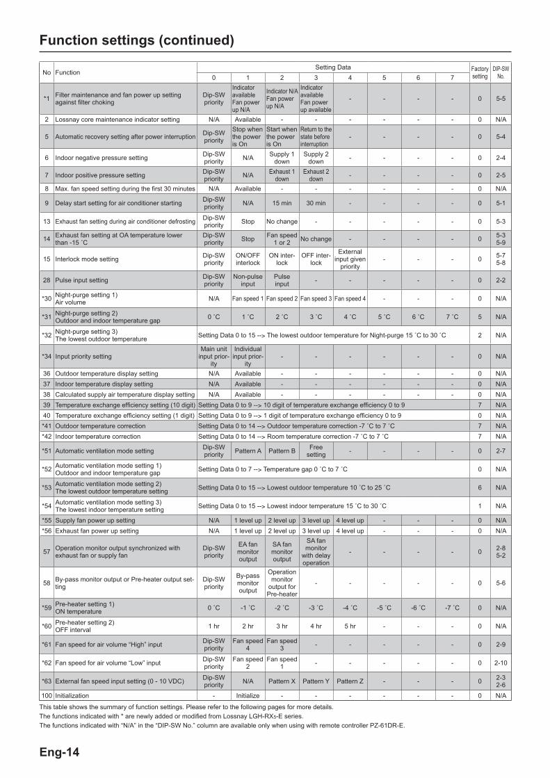
Function settings (continued)
No FunctionSetting Data Factory
settingDIP-SW
No.0 1 2 3 4 5 6 7
*1 Filter maintenance and fan power up setting against filter choking
Dip-SW priority
Indicator available Fan power up N/A
Indicator N/A Fan power up N/A
Indicator available Fan power up available
- - - - 0 5-5
2 Lossnay core maintenance indicator setting N/A Available - - - - - - 0 N/A
5 Automatic recovery setting after power interruption Dip-SW priority
Stop when the power is On
Start when the power is On
Return to the state before interruption
- - - - 0 5-4
6 Indoor negative pressure setting Dip-SW priority N/A Supply 1
downSupply 2
down - - - - 0 2-4
7 Indoor positive pressure setting Dip-SW priority N/A Exhaust 1
downExhaust 2
down - - - - 0 2-5
8 Max. fan speed setting during the first 30 minutes N/A Available - - - - - - 0 N/A
9 Delay start setting for air conditioner starting Dip-SW priority N/A 15 min 30 min - - - - 0 5-1
13 Exhaust fan setting during air conditioner defrosting Dip-SW priority Stop No change - - - - - 0 5-3
14 Exhaust fan setting at OA temperature lower than -15 ˚C
Dip-SW priority Stop Fan speed
1 or 2 No change - - - - 0 5-35-9
15 Interlock mode setting Dip-SW priority
ON/OFF interlock
ON inter-lock
OFF inter-lock
External input given
priority- - - 0 5-7
5-8
28 Pulse input setting Dip-SW priority
Non-pulse input
Pulse input - - - - - 0 2-2
*30 Night-purge setting 1) Air volume N/A Fan speed 1 Fan speed 2 Fan speed 3 Fan speed 4 - - - 0 N/A
*31 Night-purge setting 2)Outdoor and indoor temperature gap 0 ˚C 1 ˚C 2 ˚C 3 ˚C 4 ˚C 5 ˚C 6 ˚C 7 ˚C 5 N/A
*32 Night-purge setting 3) The lowest outdoor temperature Setting Data 0 to 15 --> The lowest outdoor temperature for Night-purge 15 ˚C to 30 ˚C 2 N/A
*34 Input priority settingMain unit
input prior-ity
Individual input prior-
ity- - - - - - 0 N/A
36 Outdoor temperature display setting N/A Available - - - - - - 0 N/A37 Indoor temperature display setting N/A Available - - - - - - 0 N/A38 Calculated supply air temperature display setting N/A Available - - - - - - 0 N/A39 Temperature exchange efficiency setting (10 digit) Setting Data 0 to 9 --> 10 digit of temperature exchange efficiency 0 to 9 7 N/A40 Temperature exchange efficiency setting (1 digit) Setting Data 0 to 9 --> 1 digit of temperature exchange efficiency 0 to 9 0 N/A*41 Outdoor temperature correction Setting Data 0 to 14 --> Outdoor temperature correction -7 ˚C to 7 ˚C 7 N/A*42 Indoor temperature correction Setting Data 0 to 14 --> Room temperature correction -7 ˚C to 7 ˚C 7 N/A
*51 Automatic ventilation mode setting Dip-SW priority Pattern A Pattern B Free
setting - - - - 0 2-7
*52 Automatic ventilation mode setting 1)Outdoor and indoor temperature gap Setting Data 0 to 7 --> Temperature gap 0 ˚C to 7 ˚C 0 N/A
*53 Automatic ventilation mode setting 2)The lowest outdoor temperature setting Setting Data 0 to 15 --> Lowest outdoor temperature 10 ˚C to 25 ˚C 6 N/A
*54 Automatic ventilation mode setting 3)The lowest indoor temperature setting Setting Data 0 to 15 --> Lowest indoor temperature 15 ˚C to 30 ˚C 1 N/A
*55 Supply fan power up setting N/A 1 level up 2 level up 3 level up 4 level up - - - 0 N/A*56 Exhaust fan power up setting N/A 1 level up 2 level up 3 level up 4 level up - - - 0 N/A
57 Operation monitor output synchronized with exhaust fan or supply fan
Dip-SW priority
EA fan monitor output
SA fan monitor output
SA fan monitor
with delay operation
- - - - 0 2-8 5-2
58 By-pass monitor output or Pre-heater output set-ting
Dip-SW priority
By-pass monitor output
Operation monitor
output for Pre-heater
- - - - - 0 5-6
*59 Pre-heater setting 1)ON temperature 0 ˚C -1 ˚C -2 ˚C -3 ˚C -4 ˚C -5 ˚C -6 ˚C -7 ˚C 0 N/A
*60 Pre-heater setting 2)OFF interval 1 hr 2 hr 3 hr 4 hr 5 hr - - - 0 N/A
*61 Fan speed for air volume “High” input Dip-SW priority
Fan speed 4
Fan speed 3 - - - - - 0 2-9
*62 Fan speed for air volume “Low” input Dip-SW priority
Fan speed 2
Fan speed 1 - - - - - 0 2-10
*63 External fan speed input setting (0 - 10 VDC) Dip-SW priority N/A Pattern X Pattern Y Pattern Z - - - 0 2-3
2-6100 Initialization - Initialize - - - - - - 0 N/A
This table shows the summary of function settings. Please refer to the following pages for more details.The functions indicated with * are newly added or modified from Lossnay LGH-RX5-E series.The functions indicated with “N/A” in the “DIP-SW No.” column are available only when using with remote controller PZ-61DR-E.

Eng-15
English
Function settings (continued)
No. 1 Filter maintenance and fan power up setting against filter choking
Set the schedule for filter cleaning based on the estimated concentration of dust in the air. When fan power up is available, exhaust and supply fans power up at 1,000 hrs and 2,000 hrs gradually .If function No. 55 or No. 56 is already worked, fan power up function may not available.Estimated hour differs by actual operated fan speed.
DIP-SW Setting check
PZ-61DR-E Setting check
Filter maintenance indicator
Fan power UPSW No. Setting Function No. Setting Data
SW5-5
- -
1
0(Factory setting) DIP-SW priority
- - 1 Indicate at estimated 3,000 hrs N/A
OFF (Factory setting) 2 N/A N/A
ON 3 Indicate at estimated 3,000 hrs Available
CAUTION• When the setting for the cumulative operation time of the
Lossnay is exceeded, the filter cleaning icon will appear on the indoor unit remote controller or the Lossnay remote controller. After cleaning the filter, the filter cleaning icon can be reset. Refer to the Instruction book for the remote controller.
No. 2 Lossnay core maintenance indicator setting
Set to enable Lossnay core maintenance display. Estimated hour differs by actual operated fan speed. This function is N/A from Lossnay unit DIP-SW.
DIP-SW Setting check
PZ-61DR-E Setting check
Lossnay core maintenance indicatorSW No. Setting Function No. Setting Data
N/A- -
20
(Factory setting) N/A
- - 1 Indicate at estimated 6,000 hrs
No.5 Automatic recovery setting after power interruption
Sets for automatic recovery following power interruption.
DIP-SW Setting check
PZ-61DR-E Setting check Automatic recovery
SW No. Setting Function No. Setting Data
SW5-4
- -
5
0(Factory setting) DIP-SW priority
OFF (Factory setting) 1 Stop when the power is on
- - 2 Start when the power is on
ON 3 Lossnay returns to the state before interruption
No. 6 Indoor negative pressure setting
Exhaust fan speed becomes bigger than supply fan speed.Remote controller indicates fan speed of exhaust fan.
DIP-SW Setting check
PZ-61DR-E Setting check
Down level of supply fan speedSW No. Setting Function No. Setting Data
SW2-4
- -
6
0(Factory setting) DIP-SW priority
OFF (Factory setting) 1 N/A
ON 2 Supply fan speed is 1 down to exhaust fan speed
- - 3 Supply fan speed is 2 down to exhaust fan speed
Fan speed Display
Exhaust fan
Supply fan1 down 2 down
4 4 3 23 3 2 12 2 1 11 1 1 1
No.7 Indoor positive pressure setting
Supply fan speed becomes bigger than exhaust fan speed.Remote controller indicates fan speed of supply fan.
DIP-SW Setting check
PZ-61DR-E Setting check
Down level of exhaust fan speedSW No. Setting Function No. Setting Data
SW2-5
- -
7
0(Factory setting) DIP-SW priority
OFF (Factory setting) 1 N/A
ON 2 Exhaust fan speed is 1 down to supply fan speed
- - 3 Exhaust fan speed is 2 down to supply fan speed
No.8 Max. fan speed setting during the first 30 minutes
This sets the fan to run forcibly for 30 minutes when operation starts to ventilate the indoor area. After 30 minutes, fan speed can be changed. Use this setting if the indoor air is contaminated at night when the system is shut down and you desire to ventilate the indoor area quickly when operation is started in the morning.This function is N/A from Lossnay unit DIP-SW.During this function is working, is displayed at PZ-61DR-E and selected fan speed is displayed.
DIP-SW Setting check
PZ-61DR-E Setting check
Max. fan speed setting during the first 30 minutesSW No. Setting Function No. Setting Data
N/A- -
80
(Factory setting) N/A
- - 1 Available
No.9 Delay start setting for air conditioner starting
Delays Lossnay operation for 30 minutes when City Multi or Mr. Slim starts operating or when a external device starts operating. This function is available only when Lossnay is interlocked with air conditioners. This function is N/A during Night-purge.
DIP-SW Setting check
PZ-61DR-E Setting check Lossnay delay start
SW No. Setting Function No. Setting Data
SW5-1
- -
9
0(Factory setting) DIP-SW priority
OFF (Factory setting) 1 N/A
- - 2 15 minON 3 30 min
No.13 Exhaust fan setting during air conditioner defrosting
This function can be used under the condition Lossnay supply duct is connected to Mr. Slim or City Multi indoor unit.Sets the operation of the exhaust fan during defrosting of the air conditioner (when supply fan stop).To enable this function, it is necessary to set the DIP-SW of the indoor unit also. Please refer to its manual.
DIP-SW Setting check
PZ-61DR-E Setting check
Exhaust fan operation during air conditioner defrostingSW No. Setting Function No. Setting Data
SW5-3
- -
13
0(Factory setting) DIP-SW priority
OFF (Factory setting) 1 Stop
ON 2 No change
Fan speed Display
Supply fan
Exhaust fan1 down 2 down
4 4 3 23 3 2 12 2 1 11 1 1 1

Eng-16
No.14 Exhaust fan setting at OA temperature lower than -15 ˚C
Sets the operation of the exhaust fan when the outdoor air is lower than -15 ˚C (when supply fan stop).
DIP-SW Setting check
PZ-61DR-E Setting check
Exhaust fan operation at outdoor temp. -15 ˚C or lessSW No. Setting Function No. Setting Data
SW5-3SW5-9
- -
14
0(Factory setting) DIP-SW priority
5-3 OFF5-9 ON 1 Stop
5-3 ON5-9 OFF 2 Forced to fan speed 2
or less*5-3 OFF5-9 OFF
(Factory setting) 3 No change5-3 ON5-9 ON
* In case Lossnay is operating fan speed 1, exhaust fan keeps fan speed 1. Function No. 13 and No. 14 are included in DIP-SW 5-3, then it is impossible to set independently without PZ-61DR-E.
No.15 Interlock mode setting
These settings indicate how Lossnay should operate when external devices are started or stopped.
DIP-SW Setting check
PZ-61DR-E Setting check Interlock setting
SW No. Setting Function No. Setting Data
SW5-7SW5-8
- -
15
0(Factory setting) DIP-SW priority
5-7 OFF5-8 OFF
(Factory setting)1
The Lossnay will start and stop according to the operation of the external devices. Subsequent operation will be possible using the remote controller for the Lossnay or MELANS.
5-7 ON5-8 OFF 2
The Lossnay will start whenever external devices are operated. Lossnay stop operation will be possible using its remote controller or MELANS.
5-7 OFF5-8 ON 3
The Lossnay will stop whenever external devices are stopped. Lossnay start operation will be possible using its remote controller or MELANS.
5-7 ON5-8 ON 4
The Lossnay will start and stop according to the operation of the external devices. Control via the Lossnay remote controller or MELANS will only be possible when external devices are stopped.
No.28 Pulse input setting
Set external input signal type from external device for TM2.
DIP-SW Setting check
PZ-61DR-E Setting check Pulse input setting
SW No. Setting Function No. Setting Data
SW2-2
- -
28
0(Factory setting) DIP-SW priority
OFF (Factory setting) 1 NOT pulse input
ON 2 Pulse input
Function settings (continued)
No.30 Night-purge setting 1)Air volume
Set fan speed during Night-purge. To use Night-purge function, it is necessary to set No. 30 , No. 31 , No. 32 correctly.This function is N/A from Lossnay unit DIP-SW.
DIP-SW Setting check
PZ-61DR-E Setting check
Night-purge setting 1)Air volume SW No. Setting Function No. Setting Data
N/A
- -
30
0(Factory setting)
N/A (Night-purge function is not available)
- - 1 Fan speed 1- - 2 Fan speed 2- - 3 Fan speed 3- - 4 Fan speed 4
No.31 Night-purge setting 2)Outdoor and indoor temperature gap
Set one of conditions for Night-purge start, temperature gap between indoor and outdoor.When the actual gap between indoor and outdoor becomes bigger than the setting, Night-purge starts.This function is N/A from Lossnay unit DIP-SW.
DIP-SW Setting check
PZ-61DR-E Setting check
Indoor temperature - outdoor temperatureSW No. Setting Function No. Setting Data
N/A
- -
31
0 0 ˚C or more- - 1 1 ˚C or more- - 2 2 ˚C or more- - 3 3 ˚C or more- - 4 4 ˚C or more
- - 5(Factory setting) 5 ˚C or more
- - 6 6 ˚C or more- - 7 7 ˚C or more
No.32 Night-purge setting 3)The lowest outdoor temperature
Set one of conditions for Night-purge start, maximum outdoor temperature within 24 hours.When this setting temperature is low, it is likely to start Night-purge.This function is N/A from Lossnay unit DIP-SW.
DIP-SW Setting check
PZ-61DR-E Setting check
The maximum outdoor temp. within 24 hrs SW No. Setting Function No. Setting Data
N/A
- -
32
0 15 ˚C or more- - 1 16 ˚C or more
- - 2(Factory setting) 17 ˚C or more
- - 3 18 ˚C or more- - 4 19 ˚C or more- - 5 20 ˚C or more- - 6 21 ˚C or more- - 7 22 ˚C or more- - 8 23 ˚C or more- - 9 24 ˚C or more- - 10 25 ˚C or more- - 11 26 ˚C or more- - 12 27 ˚C or more- - 13 28 ˚C or more- - 14 29 ˚C or more- - 15 30 ˚C or more
No.34 Input priority setting
Set to follow input to the main unit from air conditioner, fan speed controller, etc. This function is N/A from Lossnay unit DIP-SW.
DIP-SW Setting check
PZ-61DR-E Setting check Input priority setting
SW No. Setting Function No. Setting Data
N/A- -
340
(Factory setting) Main unit input priority
- - 1 Individual input priority

Eng-17
EnglishNo.36 Outdoor temperature display setting
Set to display outdoor temperature detected by Lossnay unit thermistor or not.This function is N/A from Lossnay unit DIP-SW.
DIP-SW Setting check
PZ-61DR-E Setting check
Outdoor temperature displaySW No. Setting Function No. Setting Data
N/A- -
36
0(Factory setting) N/A
- - 1 Display on the screen of PZ-61DR-E
No.37 Indoor temperature display setting
Set to display indoor temperature detected by Lossnay unit thermistor or not.This function is N/A from Lossnay unit DIP-SW.
DIP-SW Setting check
PZ-61DR-E Setting check
Indoor temperature displaySW No. Setting Function No. Setting Data
N/A- -
37
0(Factory setting) N/A
- - 1 Display on the screen of PZ-61DR-E
No.38 Calculated supply air temperature display setting
Set to display calculated supply air temperature or not.This function is N/A from Lossnay unit DIP-SW.
DIP-SW Setting check
PZ-61DR-E Setting check
Calculated supply temperature displaySW No. Setting Function No. Setting Data
N/A- -
38
0(Factory setting) N/A
- - 1 Display on the screen of PZ-61DR-E
No.39, 40 Temperature exchange efficiency setting
Set the 10 digit of temperature exchange efficiency which is used to calculate supply air temperature. This function is N/A from Lossnay unit DIP-SW.
DIP-SW Setting check
PZ-61DR-E Setting check
10 digit of temperature exchange efficiencySW No. Setting Function No. Setting Data
N/A
- -
39
0 0- - 1 1- - 2 2- - 3 3- - 4 4- - 5 5- - 6 6
- - 7(Factory setting) 7
- - 8 8- - 9 9
DIP-SW Setting check
PZ-61DR-E Setting check
1 digit of temperature exchange efficiencySW No. Setting Function No. Setting Data
N/A
- -
40
0(Factory setting) 0
- - 1 1- - 2 2- - 3 3- - 4 4- - 5 5- - 6 6- - 7 7- - 8 8- - 9 9
Function settings (continued)
No.41 Outdoor temperature correction
Set the correction for the outdoor temperature displayed on the PZ-61DR-E screen by function No. 36 .This function is N/A from Lossnay unit DIP-SW.
DIP-SW Setting check
PZ-61DR-E Setting check
The correction to thermistor detectionSW No. Setting Function No. Setting Data
N/A
- -
41
0 -7 ˚C- - 1 -6 ˚C- - 2 -5 ˚C- - 3 -4 ˚C- - 4 -3 ˚C- - 5 -2 ˚C- - 6 -1 ˚C
- - 7(Factory setting) 0 ˚C
- - 8 +1 ˚C- - 9 +2 ˚C- - 10 +3 ˚C- - 11 +4 ˚C- - 12 +5 ˚C- - 13 +6 ˚C- - 14 +7 ˚C
No.42 Indoor temperature correction
Set the correction for the indoor temperature displayed on the PZ-61DR-E screen by function No. 37 .This function is N/A from Lossnay unit DIP-SW.
DIP-SW Setting check
PZ-61DR-E Setting check
The correction to thermistor detectionSW No. Setting Function No. Setting Data
N/A
- -
42
0 -7 ˚C- - 1 -6 ˚C- - 2 -5 ˚C- - 3 -4 ˚C- - 4 -3 ˚C- - 5 -2 ˚C- - 6 -1 ˚C
- - 7(Factory setting) 0 ˚C
- - 8 +1 ˚C- - 9 +2 ˚C- - 10 +3 ˚C- - 11 +4 ˚C- - 12 +5 ˚C- - 13 +6 ˚C- - 14 +7 ˚C
No.51 Automatic ventilation mode setting
Set the pattern of conditions to go into By-pass mode in automatic ventilation operation.When setting Data is set “3” by PZ-61DR-E, function No. 52 , No. 53 , and No. 54 are available.
DIP-SW Setting check
PZ-61DR-E Setting check
Conditions to go into By-pass modeSW No. Setting Function No. Setting Data
SW2-7
- -
51
0(Factory setting) DIP-SW priority
OFF (Factory setting) 1
Pattern A Indoor temperature is 16 ˚C or more Outdoor temperature is 16 ˚C or moreIndoor temperature - outdoor temperature ≥ 0 ˚C
ON 2
Pattern B Indoor temperature is 22 ˚C or more Outdoor temperature is 18 ˚C or moreIndoor temperature - outdoor temperature ≥ 2 ˚C
- - 3 Free setting
* Pattern A is more likely to become By-pass mode than pattern B.

Eng-18
Note;The ventilation mode follows the table below.
Remote controller Interlocked air conditioner (Mr. Slim or City Multi) Lossnay
Energy recovery ventilation mode Either Yes or No
Energy recovery ventilation mode
By-pass ventilation mode By-pass ventilation mode
AutomaticCooling/Stop Automatic (Follows the map)
Other than above Always energy recovery ventilation mode
No.52 Automatic ventilation mode setting 1)Outdoor and indoor temperature gap
Set one of conditions for By-pass mode in auto ventilation operation, temperature gap between indoor and outdoor.This function is N/A from Lossnay unit DIP-SW.This function is available when setting Data 3 is selected at function No. 51.
DIP-SW Setting check
PZ-61DR-E Setting check
Indoor temperature - outdoor temperatureSW No. Setting Function No. Setting Data
N/A
- -
52
0(Factory setting) 0 ˚C or more
- - 1 1 ˚C or more - - 2 2 ˚C or more - - 3 3 ˚C or more- - 4 4 ˚C or more- - 5 5 ˚C or more- - 6 6 ˚C or more- - 7 7 ˚C or more
No.53 Automatic ventilation mode setting 2)The lowest outdoor temperature
Set one of conditions for By-pass mode in auto ventilation operation, minimum outdoor temperature which comes in indoor directly.This function is N/A from Lossnay unit DIP-SW.This function is available when setting Data 3 is selected at function No. 51.
DIP-SW Setting check
PZ-61DR-E Setting check Outdoor temperature
SW No. Setting Function No. Setting Data
N/A
- -
53
0 10 ˚C or more- - 1 11 ˚C or more- - 2 12 ˚C or more- - 3 13 ˚C or more- - 4 14 ˚C or more- - 5 15 ˚C or more
- - 6(Factory setting) 16 ˚C or more
- - 7 17 ˚C or more- - 8 18 ˚C or more- - 9 19 ˚C or more- - 10 20 ˚C or more- - 11 21 ˚C or more- - 12 22 ˚C or more- - 13 23 ˚C or more- - 14 24 ˚C or more- - 15 25 ˚C or more
Function settings (continued)
No.54 Automatic ventilation mode setting 3)The lowest indoor temperature setting
Set one of conditions for By-pass mode in auto ventilation operation, minimum indoor temperature.This function is N/A from Lossnay unit DIP-SW.This function is available when setting Data 3 is selected at function No. 51.When Lossnay is interlocked to Mr. Slim or City Multi indoor unit, the target temperature of the indoor unit is the lowest indoor temperature for By-pass mode
DIP-SW Setting check
PZ-61DR-E Setting check Indoor temperature
SW No. Setting Function No. Setting Data
N/A
- -
54
0 15 ˚C or more
- - 1(Factory setting) 16 ˚C or more
- - 2 17 ˚C or more- - 3 18 ˚C or more- - 4 19 ˚C or more- - 5 20 ˚C or more- - 6 21 ˚C or more- - 7 22 ˚C or more- - 8 23 ˚C or more- - 9 24 ˚C or more- - 10 25 ˚C or more- - 11 26 ˚C or more- - 12 27 ˚C or more- - 13 28 ˚C or more- - 14 29 ˚C or more- - 15 30 ˚C or more
Free By-pass settingUser can set conditions to go into By-pass mode in automatic ventilation mode by function No. 52 , No. 53 and No. 54.Setting examples are shown below.Example 1*
By-pass/Energy recovery ventilation map in automatic ventilation mode
Function No. Setting Data52 0 (0 ˚C)53 0 (10 ˚C)54 2 (17 ˚C)
8
8
10
12
14
16
18
20
22
24
26
28
30
32
34
36
38
40
1210 14 1816 20 22 24 26 28 30 32 34 36 38 40
Out
door
tem
pera
ture
(˚C
)
Indoor temperature (˚C)
Set by function No. 53
Energy recovery ventilation area
By-pass ventilation area
Set by function No. 52
Set by function No. 54 (Terget temp. of air conditioner)

Eng-19
English
Example 2By-pass/Energy recovery ventilation map in automatic ventilation mode
Function No. Setting Data52 5 (5 ˚C)53 1 (11 ˚C)54 7 (22 ˚C)
When the setting of Function No. 53 is low, with using the pre-heater function, the outdoor temperature may be detected as higher and the mode may change to By-pass mode even in winter. Set the setting 16 ˚C or more, or use energy recovery ventilation mode.
No.55, 56 Supply fan power up settingExhaust fan power up setting
Use these functions when the air volume is needed to be up after installation.Function No. 55 is for supply fan power up and function No. 56 is for exhaust fan power up.When function No. 1 is on and fan speed already reached the maximum power, this function is N/A.These functions are N/A from Lossnay unit DIP-SW.
DIP-SW Setting check
PZ-61DR-E Setting check Supply fan power up
SW No. Setting Function No. Setting Data
N/A
- -
55
0(Factory setting) N/A
- - 1 1 level up- - 2 2 level up- - 3 3 level up- - 4 4 level up
DIP-SW Setting check
PZ-61DR-E Setting check Exhaust fan power up
SW No. Setting Function No. Setting Data
N/A
- -
56
0(Factory setting) N/A
- - 1 1 level up- - 2 2 level up- - 3 3 level up- - 4 4 level up
88
10
12
14
16
18
20
22
24
26
28
30
32
34
36
38
40
1210 14 1816 20 22 24 26 28 30 32 34 36 38 40
Out
door
tem
pera
ture
(˚C
)
Indoor temperature (˚C)
Energy recovery ventilation area
By-pass ventilation area
Set by function No. 53
Set by function No. 52
Set by function No. 54 (Terget temp. of air conditioner)
Function settings (continued)
No.57 Operation monitor output synchronized with exhaust fan or supply fan
Set operation monitor output from TM3 90 synchronized with supply of exhaust fan.Also supply fan delay operation, ex. for after-heater, can be set.
DIP-SW Setting check
PZ-61DR-E Setting check
Operation monitor output from TM390SW No. Setting Function No. Setting Data
SW2-8SW5-2
- -
57
0(Factory setting) DIP-SW priority
2-8 OFF5-2 OFF
(Factory setting)1 EA fan monitor output
2-8 OFF5-2 ON 2
SA fan monitor output* When supply fan stops during cold outdoor temp. or defrosting, output stops.
2-8 ON(Either 5-2 ON or OFF)
3
Operation monitor output corresponds with supply fan with following.Starts the output 10 seconds after supply fan operates.Fan continues to operate supply fan for 3 min after stopping the output.
To use SW2-8 as the after-heater, observe the cautions listed in 4 on the page 11.
No.58 By-pass monitor output or Pre-heater output setting
Set By-pass monitor or Pre-heater output from TM3 70 synchronized with supply of exhaust fan.
DIP-SW Setting check
PZ-61DR-E Setting check
Output setting from TM370SW No. Setting Function No. Setting Data
SW5-6
- -
58
0(Factory setting) DIP-SW priority
OFF (Factory setting) 1
By-pass ventilation operation monitor output. Corresponds to operation mode output of By-pass damper.
ON 2
Pre-heater output.Corresponds to operation output supply fan with following. Start the output 10 seconds after supply fan starts. Fan continues to operate for 3 min after stopping the output. Lossnay starts output when outdoor temp. 0˚C or less, and stops output when detecting temp. becomes 15˚C. Lossnay stop the output every 1 hour. Error code is shown on the remote controller and stop the output in case of following.1) TH1 detects higher than 15 ˚C within 15 minutes after the output starts.2) TH1 detects -10 ˚C or lower, 60 minutes after the output starts.
- For heater selection, observe the cautions listed in 4 on the page 11.
- When set to auto ventilation mode while using the Pre-heater function, the outdoor temperature may be detected as higher and the mode may change to By-pass mode, even in winter.
- During pre-heater is ON, Lossnay does not go to Fan speed 1. Even remote controller displays Fan speed 1, Lossnay is operated at Fan speed 2.

Eng-20
No.59 Pre-heater output setting 1)ON temperature
Set the outdoor temperature for Pre-heater output ON.When detecting temp. becomes the setting or less, Pre-heater output from TM370 starts.This function is N/A from Lossnay unit DIP-SW.
DIP-SW Setting check
PZ-61DR-E Setting check
Outdoor temp. for Pre-heater output ONSW No. Setting Function No. Setting Data
N/A
- -
59
0(Factory setting) 0 ˚C or less
- - 1 -1 ˚C or less- - 2 -2 ˚C or less- - 3 -3 ˚C or less- - 4 -4 ˚C or less- - 5 -5 ˚C or less- - 6 -6 ˚C or less- - 7 -7 ˚C or less
No.60 Pre-heater output setting 2)OFF interval
Set the Pre-heater output interval. Output stops according to the set hours.
DIP-SW Setting check
PZ-61DR-E Setting check
Pre-heater output OFF intervalSW No. Setting Function No. Setting Data
N/A
- -
60
0(Factory setting) 1 hr
- - 1 2 hrs- - 2 3 hrs- - 3 4 hrs- - 4 5 hrs
No.61 Fan speed for air volume “High” input
Set the fan speed setting when receiving “High” signal from remote controllers(e.g. remote controller of City Multi and Mr. Slim, Lossnay simple remote controller) which have High/Low or High/Middle/Low air volume.
DIP-SW Setting check
PZ-61DR-E Setting check Operating fan speed
SW No. Setting Function No. Setting Data
SW2-9
- -
61
0(Factory setting) DIP-SW priority
OFF (Factory setting) 1 Fan speed 4
ON 2 Fan speed 3
No.62 Fan speed for air volume “Low” input
Set the fan speed setting when receiving “Low” signal from remote controllers(e.g. remote controller of City Multi and Mr. Slim, Lossnay simple remote controller) which have High/Low.
DIP-SW Setting check
PZ-61DR-E Setting check Operating fan speed
SW No. Setting Function No. Setting Data
SW2-10
- -
62
0(Factory setting) DIP-SW priority
OFF (Factory setting) 1 Fan speed 2
ON 2 Fan speed 1
Function settings (continued)
No.63 External fan speed input setting (0 - 10 VDC)
Set external fan speed input setting.
DIP-SW Setting check
PZ-61DR-E Setting check
External fan speed control using CN26SW No. Setting Function No. Setting Data
SW2-3SW2-6
- -
63
0(Factory setting) DIP-SW priority
2-3 OFF2-6 OFF
(Factory setting)1 External fan speed
control is N/A.
2-3 ON2-6 OFF 2 Refer to pattern X
2-3 OFF2-6 ON 3 Refer to pattern Y
2-3 ON2-6 ON 4 Refer to pattern Z
Lossnay changes fan speed according to input voltage to CN26.When pattern X or Y is selected, it is not possible to change fan speed from remote controllers.(External input has higher priority)[Pattern X]
When the input voltage is more than 6.0 VDC, Lossnay operates at fan speed 4 (maximum air volume). Lower voltage than 6.0 VDC, Lossnay operate at weaker fan speed. (Connection example: if you use a CO2 sensor which 0 - 10 VDC equals to 0 - 2000 ppm, 6.0 VDC equals to 1200 ppm)
[Pattern Y]When the input voltage is more than 5.0 VDC, Lossnay operates at fan speed 4 (maximum air volume). Lower voltage than 5.0 VDC, Lossnay operate at weaker fan speed. (Connection example,:if you use a CO2 sensor which 0 - 10 VDC equals to 0 -2000 ppm, 5.0 VDC equals to 1000 ppm)
[Pattern Z]Lossnay changes fan speed as the table below. (Connection example: BMS (Building Management System))
Input voltage[VDC] Fan speed Fan speed changing from Remote controller
0 - 1.0 - Available1.5 - 2.5 1 Not available3.5 - 4.5 2 Not available5.5 - 7 3 Not available8.5 - 10 4 Not available
When the input voltage is in-between, it will cause unstable operation.
No.100 Initialization
Set to initialize the remote PZ-61DR-E setting.All settings which are changed by users are cancelled.
DIP-SW Setting check
PZ-61DR-E Setting check Initialization
SW No. Setting Function No. Setting Data
N/A- -
1000 N/A
- - 1 Available

Eng-21
English
Trial operationAfter the system has been installed and before the ceiling panel is installed, make sure that wires are properly connected, then test the system’s operation, referring to the operation manual for the remote controller.
1. Trial operation using the remote controllers (PZ-61DR-E) Follow the procedure shown in the operation manual for the remote controller the functions below.
(1) Start operation.(2) Fan speed selection. (3) Ventilation mode selection.(4) Stop operation.
2. Lossnay trial operationThis function can be used following situations.
• When there is no remote controller installed for operating the Lossnay.• When heater output, malfunction monitor output, operation monitor output, and other output are connected.• When the outdoor temperature is 8ºC or lower. (To check By-pass damper operation) (1) Supply power to the Lossnay unit.(2) Turn the trial operation switch (DIP-SW SW2-1) “On.”
Terminal DIP-SW SettingMinutes 0 1 2 3 4
Seconds 0 10 20 30 40 50 0 10 20 30 40 50 0 10 20 30 40 50 0 10 20 30 40 50 0 10 20 30 40 50- - - FanSpeed STOP 4 STOP 4- - - Ventilation mode Bypass Lossnay
TM370 SW5-6 OFF Bypass monitor output OFF ON OFFON Pre-heater output OFF ON
TM390 SW2-8/SW5-2
OFF/OFF EA fan monitor output ONOFF/ON SA fan monitor output ONON/OFF or ON/ON
SA fan monitor output delay operation OFF ON
TM380 - - Malfunction monitor output ON
Error code “0900” appears on the remote controller.
(3) Check each function operating normally.(4) Turn the trial operation switch (DIP-SW SW2-1) “Off.”
Check points after installation workAfter installation work, please double-check the points below. If there is any trouble, it must be done correctly.
(1) Check points - Unit installation Is the insulation wrapped around the outside ducts? [Refer to Installing the Lossnay unit] page 5 Is the outside ducts installed correctly? [Refer to Installation example] page 5
(2) Check points - Wiring work Is the power supply voltage correct? [Refer to wiring diagram] page 7-8 Is the wiring work the same as wiring diagram? [Refer to wiring diagram] page 7-8 Is the power supply cable connected to the terminal (TM1) certainly? [Refer to Connecting the power supply cable] page 9 Is the ground cable connected to the screw certainly? [Refer to Connecting the power supply cable] page 9 Are the cables properly secured using the cord clip and the PG connector? [Refer to Connecting the power supply cable] page 9
3. Complete system trial operationnInterlock system containing an indoor unit and/or external device• Use the remote controller for the indoor unit or the operating switches for the external device and confirm that the indoor unit and Lossnay are
interlocked.• If delay time has been set, check that the Lossnay operates after the delay time has passed.nIf MELANS System• Use MELANS to confirm the operation of the Lossnay.

Eng-22
4. If trouble occurs during trial operationSymptom Remedy
Will not operate even when the operation switch for the remote controller (PZ-61DR-E) is pressed.
• Check the power supply. (The specified power supply is single-phase 220-240 V 50 Hz)• Check for a short circuit or disconnection in the transmission cable. (Check that the voltage between
terminals in the transmission cables is 10 to 13 VDC for the PZ-61DR-E.)• Check that the there is 5 cm or more separating the transmission cable from the power supply cable
and any other transmission cables.• Run the Lossnay independently using the trial operation switch (SW2-1) and check if it runs.
Lossnay runs --> Check the signal linesLossnay doesn’t run --> Check the power supply
• Check if there are three or more remote controller connected. (The maximum is two.)When using M-NET, the operation switch of Remote Controller (PZ-61DR-E) is dead.
• Check the power supply. (Specified power supply: single-phase 220-240 V 50 Hz, wire dia. ø1.6, switch capacity
• Check if the power supply unit is connected or not, and if the power is supplied or not (For a system with Lossnay only, it is necessary to install the power supply unit.)
• Check the transmission cable for short-circuit or broken wire (Check if DC 20 - 30 V is detected between the terminals of transmission cable).
• Check if a clearance of 5 cm is secured between the transmission cable and the Power supply cable and other transmission cables.
• Run Lossnay independently to see if it operates properly or not.
Lossnay operates --> Inspect the transmission cableLossnay doesn’t operate --> Check the power supply
Does not operate even when the operation switch for remote controller for MELANS is pressed.
• Check whether or not there is a power supply unit and that the power has been turned on. (On systems with only a Lossnay, a power supply unit is required.)
Indoor unit or external device does not interlock.
• Check if the pulse input switch (SW2-2) is off. (Can be set from PZ-61DR-E)• Check the overall cable length between the indoor unit or external device and Lossnay. (Refer to
technical publications or other such documents.)• Check the connections at the external control input terminal block (TM2). In the case of voltage charged 12 or 24 VDC output device: Connect to external control input terminals 1 and 2.
In the case of uncharged a-contact output device: Connect to external control input terminals 1 and 3. In the case of Mr. Slim (A control or K control): Connect to external control input terminals 1 and 2.• Perform the registration operation using the remote control for the air conditioner or MELANS. (Refer to
the installation instructions for the remote controller for the indoor unit or MELANS.)• Check if the delay has been set.• Check the overall length of the transmission cable between the external device and Lossnay. (Refer to
technical publications or other such documents.)• Check if the transmission cable from the external device has come off of the external control input terminal.
Operation signal Stop signalCharged 12 or 24 VDC output device 12 or 24 VDC 0 VDCUncharged a-contact output device Resistance: 0 Ω Unlimited resistance ΩMr. Slim 2 to 6 VDC (pulse signal) 2 to 6 VDC (pulse signal)
• Check, in the case of multiple units, whether the DIPSW SW5-10 of the Lossnay unit which is connected to the external control input terminal is set ON, and check whether the DIPSW SW5-10 of other Lossnay units are set to OFF.
Lossnay does not stop. • Check that the trial operation switch (SW2-1) is set to off.The inspection indicator lamp (LED 1 Green) in the control box flashes.
1 flash Fault on supply fan motor
Turn the power off and consult your dealer.
2 flashes Fault on exhaust fan motor4 flashes Fault on OA thermistor5 flashes Fault on RA thermistor6 flashes Fault on supply fan motor (Only LGH-150/200RVX-E)7 flashes Fault on exhaust fan motor (Only LGH-150/200RVX-E)8 flashes Fault on Pre-heater capacity or relay of TM370
9 flashes Fault on remote controller communication10 flashes Fault on function setting11 flashes Fault on power supply to remote controller
The inspection indicator lamp (LED 2 Red ) in the control box flashes.
1 to 8 flashes
Error in M-NET communication Turn off the power and immediately contact your dealer.
nWhen an inspection number blinks on the remote controller, follow the procedures shown in the installation and operating manuals provided with the remote controller.
nIf the remote controller is not used, operate after approximately 2 minutes of turning on the power for the Lossnay.
Trial operation (continued)


![dl.mitsubishielectric.co.jp · 2019-11-07 · 1/1 lb- lb-odf6 lf-ûx2 lb-okx5 lp-a lpb-c]kx5 lb-obf7 lgh-nÛrs2 lgh-nÜrs2dÜ* lgh-nûrs3 lgh-nûrs3d lgh-nc]rx 500—5000 atž250,](https://static.fdocuments.net/doc/165x107/5e51f7fccbd97e57577c924b/dl-2019-11-07-11-lb-lb-odf6-lf-x2-lb-okx5-lp-a-lpb-ckx5-lb-obf7-lgh-nrs2.jpg)


