Lg Multi Space
226
System Air Conditioner SERVICE MANUAL R410A LG MODELS: ARUN/ARUV Series ARNU Series website http://www.lgservice.com CAUTION • BEFORE SERVICING THE UNIT, READ THE SAFETY PRECAUTIONS IN THIS MANUAL. • ONLY FOR AUTHORIZED SERVICE PERSONNEL.
-
Upload
andre-soares-mota -
Category
Documents
-
view
79 -
download
3
description
service manual
Transcript of Lg Multi Space
SystemAir ConditionerSERVICE MANUAL R410A
LG
MODELS: ARUN/ARUV SeriesARNU Series
website http://www.lgservice.com
CAUTION
• BEFORE SERVICING THE UNIT, READ THE SAFETY PRECAUTIONS IN THIS MANUAL.
• ONLY FOR AUTHORIZED SERVICE PERSONNEL.
2
Air Conditioner Service Manual
TABLE OF CONTENTS
Safety Precautions .......................................................................................3
Model Names ..............................................................................................11
External Appearance ..................................................................................12
Nomenclature ..............................................................................................14
Outdoor Units Information .........................................................................15
Indoor Units...........................................................................................17
Ceiling Mounted Cassette Type (4 way)....................................................19
Art Cool Type ............................................................................................31
Art Cool Type(Wide)..................................................................................45
Ceiling Concealed Duct Type (Low static) ................................................58
Ceiling Concealed Duct Type (High static)................................................68
Outdoor Units.......................................................................................79
Trouble shooting guide ............................................................................113
Exploded View & Replacement Parts List ..............................................183
Service Manual 3
Safety Precautions
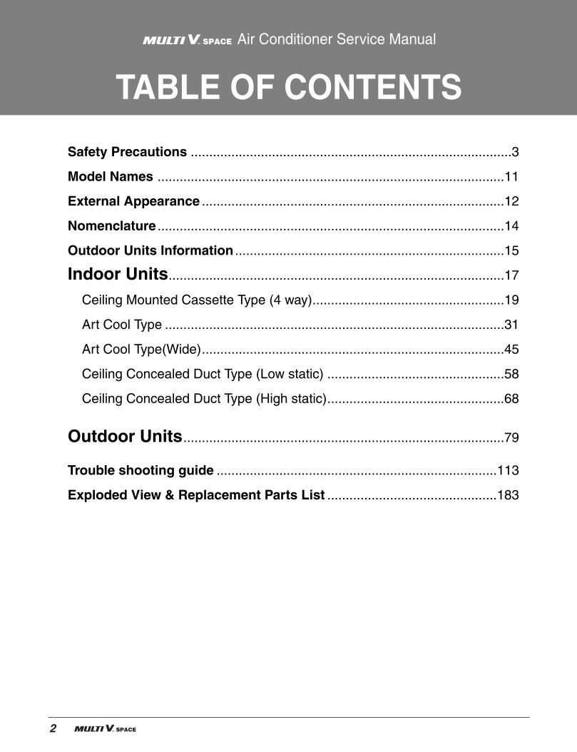
Safety PrecautionsTo prevent injury to the user or other people and property damage, the following instructions mustbe followed. Incorrect operation due to ignoring instruction will cause harm or damage. The seriousness is
classified by the following indications.
Meanings of symbols used in this manual are as shown below.
WARNING
CAUTION
This symbol indicates the possibility of death or serious injury.
This symbol indicates the possibility of injury or damage to properties only.
Be sure not to do.
Be sure to follow the instruction.
WARNING Installation
Have all electric work done by a licensed electri-cian according to "Electric Facility EngineeringStandard" and "Interior Wire Regulations" and theinstructions given in this manual and always use aspecial circuit.
• If the power source capacity is inadequate or electricwork is performed improperly, electric shock and firemay result.
Ask the dealer or an authorized technician toinstall the air conditioner.
• Improper installation by the user may result in waterleakage, electric shock, or fire.
Always ground the product.
• There is risk of fire or electric shock.
Always intstall a dedicated circuit and breaker.
• Improper wiring or installation may cause fire or elec-tric shock.

4
Safety Precautions
For re-installation of the installed product, alwayscontact a dealer or an Authorized Service Center.
• There is risk of fire, electric shock, explosion, or injury.
Do not install, remove, or re-install the unit byyourself (customer).
• There is risk of fire, electric shock, explosion, or injury.
Do not store or use flammable gas orcombustibles near the air conditioner.
• There is risk of fire or failure of product.
Use the correctly rated breaker or fuse.
• There is risk of fire or electric shock.
Prepare for typhoons and other strong winds andearthquakes and install the unit at the specifiedplace.
• Improper installation may cause the unit to topple andresult in injury.
Do not install the product on a defective installa-tion stand.
• It may cause injury, accident, or damage to the prod-uct.
When installing and moving the air conditioner toanother site, do not charge it with adiffernet refrigerant from the refrigerant specifiedon the unit.
• If a differnet refrigerant or air is mixed with the originalrefrigerant, the refrigerant cycle may malfunction andthe unit may be gamaged.
Do not reconstruct to change the settings of theprotection devices.
• If the pressure switch, thermal switch, or other protec-tion device is shorted and operated forcibly, or partsother than those specified by LGE are used, fire orexplosion may result.
Gasolin
Service Manual 5
Safety Precautions
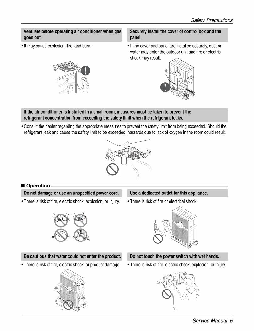
Ventilate before operating air conditioner when gasgoes out.
• It may cause explosion, fire, and burn.
Securely install the cover of control box and thepanel.
• If the cover and panel are installed securely, dust orwater may enter the outdoor unit and fire or electricshock may result.
If the air conditioner is installed in a small room, measures must be taken to prevent therefrigerant concentration from exceeding the safety limit when the refrigerant leaks.
• Consult the dealer regarding the appropriate measures to prevent the safety limit from being exceeded. Should therefrigerant leak and cause the safety limit to be exceeded, harzards due to lack of oxygen in the room could result.
OperationDo not damage or use an unspecified power cord.
• There is risk of fire, electric shock, explosion, or injury.
Use a dedicated outlet for this appliance.
• There is risk of fire or electrical shock.
Be cautious that water could not enter the product.
• There is risk of fire, electric shock, or product damage.
Do not touch the power switch with wet hands.
• There is risk of fire, electric shock, explosion, or injury.
6
Safety Precautions
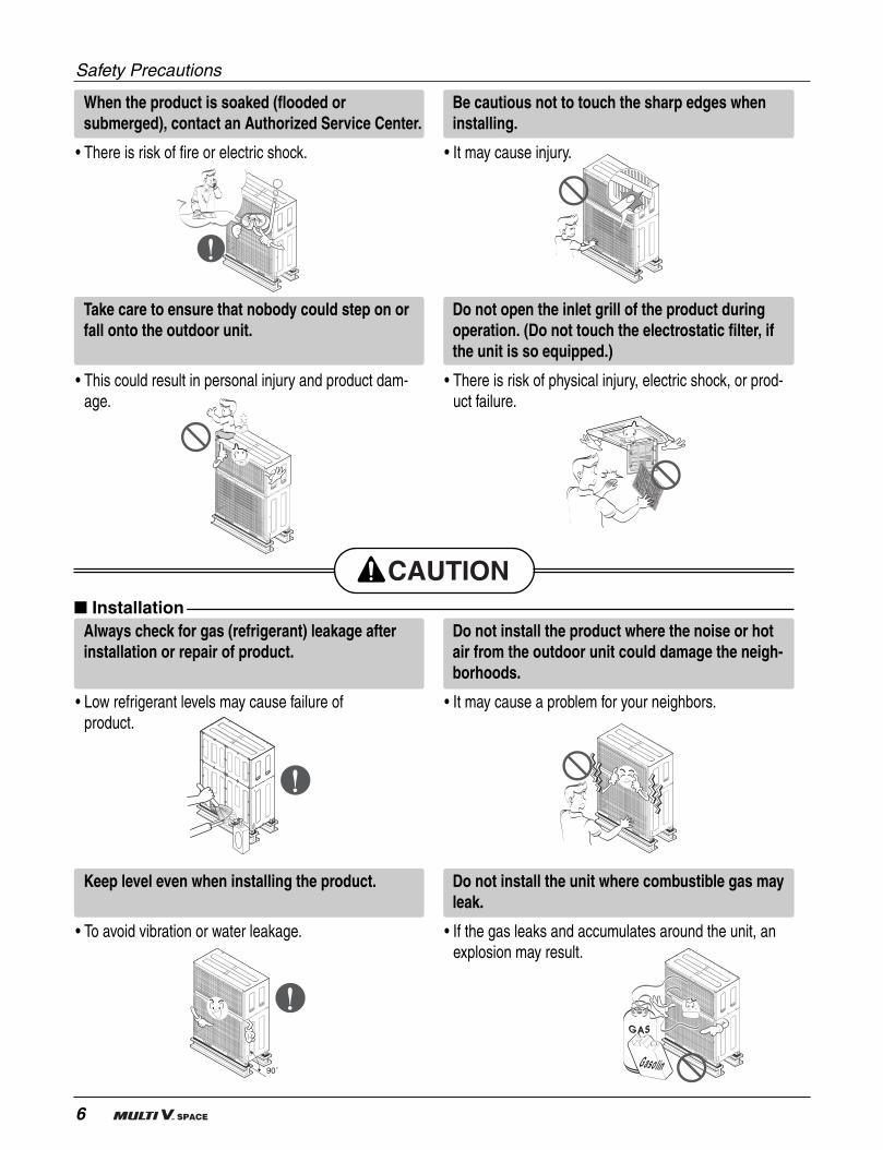
When the product is soaked (flooded orsubmerged), contact an Authorized Service Center.
• There is risk of fire or electric shock.
Be cautious not to touch the sharp edges wheninstalling.
• It may cause injury.
Take care to ensure that nobody could step on orfall onto the outdoor unit.
• This could result in personal injury and product dam-age.
Do not open the inlet grill of the product duringoperation. (Do not touch the electrostatic filter, ifthe unit is so equipped.)
• There is risk of physical injury, electric shock, or prod-uct failure.
InstallationAlways check for gas (refrigerant) leakage afterinstallation or repair of product.
• Low refrigerant levels may cause failure ofproduct.
Do not install the product where the noise or hotair from the outdoor unit could damage the neigh-borhoods.
• It may cause a problem for your neighbors.
Keep level even when installing the product.
• To avoid vibration or water leakage.
Do not install the unit where combustible gas mayleak.
• If the gas leaks and accumulates around the unit, anexplosion may result.
90˚Gasolin

Service Manual 7
Safety Precautions
Use power cables of sufficient currentcarrying capacity and rating.
• Cables that are too small may leak, generate heat, andcause a fire.
Do not use the product for special purposes, suchas preserving foods, works of art, etc. It is a con-sumer air conditioner, not a precision refrigerationsystem.
• There is risk of damage or loss of property.
Keep the unit away from children. The heatexchanger is very sharp.
• It can cause the injury, such as cutting the finger. Alsothe gamaged fin may result in degradation of capacity.
When installting the unit in a hospital, communica-tion station, or similar place, provide surfficientprotection against noise.
• The inverter equipment, private power generator, high-frequency medical equipment, or radio communicationequipment may cause the air conditioner to operateerroneously, or fail to operate. On the other hand, theair conditioner may affect such equipment by creatingnoise that disturbs medical treatment or image broad-casting.
Do not install the product where it will be exposed to sea wind (salt spray) directly.
• It may cause corrosion on the product. Corrosion, particularly on the condenser and evaporator fins, could causeproduct malfunction or inefficient operation.
8
Safety Precautions
Operation
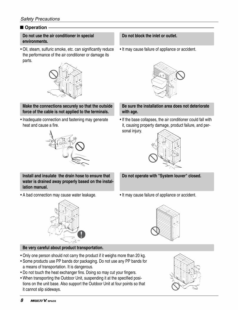
Do not use the air conditioner in specialenvironments.
• Oil, steam, sulfuric smoke, etc. can significantly reducethe performance of the air conditioner or damage itsparts.
Do not block the inlet or outlet.
• It may cause failure of appliance or accident.
Make the connections securely so that the outsideforce of the cable is not applied to the terminals.
• Inadequate connection and fastening may generateheat and cause a fire.
Be sure the installation area does not deterioratewith age.
• If the base collapses, the air conditioner could fall withit, causing property damage, product failure, and per-sonal injury.
Be very careful about product transportation.
• Only one person should not carry the product if it weighs more than 20 kg.• Some products use PP bands dor packaging. Do not use any PP bands for
a means of transportation. It is dangerous.• Do not touch the heat exchanger fins. Doing so may cut your fingers.• When transporting the Outdoor Unit, suspending it at the specified posi-
tions on the unit base. Also support the Outdoor Unit at four points so thatit cannot slip sideways.
Install and insulate the drain hose to ensure thatwater is drained away properly based on the instal-lation manual.
• A bad connection may cause water leakage.
Do not operate with "System louver" closed.
• It may cause failure of appliance or accident.
Service Manual 9
Safety Precautions
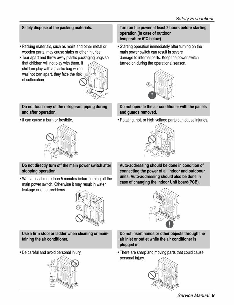
Safely dispose of the packing materials.
• Packing materials, such as mails and other metal orwooden parts, may cause stabs or other injuries.
• Tear apart and throw away plastic packaging bags sothat children will not play with them. Ifchildren play with a plastic bag whichwas not torn apart, they face the riskof suffocation.
Turn on the power at least 2 hours before startingoperation.(In case of outdoortemperature 5°C below)
• Starting operation immediately after turning on themain power switch can result in severedamage to internal parts. Keep the power switchturned on during the operational season.
Do not touch any of the refrigerant piping duringand after operation.
• It can cause a burn or frostbite.
Do not operate the air conditioner with the panelsand guards removed.
• Rotating, hot, or high-voltage parts can cause injuries.
Do not directly turn off the main power switch afterstopping operation.
• Wait at least more than 5 minutes before turning off themain power switch. Otherwise it may result in waterleakage or other problems.
Auto-addressing should be done in condition ofconnecting the power of all indoor and outdoourunits. Auto-addressing should also be done incase of changing the Indoor Unit board(PCB).
Use a firm stool or ladder when cleaning or main-taining the air conditioner.
• Be careful and avoid personal injury.
Do not insert hands or other objects through theair inlet or outlet while the air conditioner isplugged in.
• There are sharp and moving parts that could causepersonal injury.
10
Part 1General Information
1. Model Names ................................................................111.1 Indoor Unit .............................................................111.2 Outdoor Unit ..........................................................11
2. External Appearance.....................................................122.1 Indoor Unit .............................................................122.2 Outdoor Unit ..........................................................13
3. Nomenclature.................................................................143.1 Indoor Unit .............................................................143.2 Outdoor Unit ..........................................................14
4. Outdoor Units information............................................15
Service Manual 11
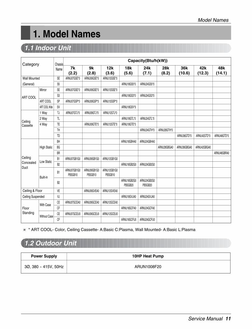
1. Model Names1.1 Indoor Unit
1.2 Outdoor Unit
Model Names
Power Supply 10HP Heat Pump
3Ø, 380 ~ 415V, 50Hz ARUN1008F20
Wall Mounted SE ARNU07GSE*0 ARNU09GSE*0 ARNU12GSE*0
(General) S5 ARNU18GS5*0 ARNU24GS5*0
Mirror SE ARNU07GSE*0 ARNU09GSE*0 ARNU12GSE*0
S3 ARNU18GS3*0 ARNU24GS3*0
ART COOL SP ARNU07GSP*0 ARNU09GSP*0 ARNU12GSP*0
ART COOL Wide SV ARNU18GSV*0
1 Way TJ ARNU07GTJ*0 ARNU09GTJ*0 ARNU12GTJ*0
2 Way TL ARNU18GTL*0 ARNU24GTL*0
4 Way TE ARNU09GTE*0 ARNU12GTE*0 ARNU18GTE*0
TH ARNU24GTH*0 ARNU28GTH*0
TD ARNU36GTD*0 ARNU42GTD*0 ARNU48GTD*0
BH ARNU18GBHA0 ARNU24GBHA0
High Static BG ARNU28GBGA0 ARNU36GBGA0 ARNU42GBGA0
BR ARNU48GBRA0
Low StaticB1 ARNU07GB1G0 ARNU09GB1G0 ARNU12GB1G0
B2 ARNU18GB2G0 ARNU24GB2G0
B1 ARNU07GB1G0 ARNU09GB1G0 ARNU12GB1G0
Built-inPBSGB10 PBSGB10 PBSGB10
B2 ARNU18GB2G0 ARNU24GB2G0PBSGB20 PBSGB20
VE ARNU09GVEA0 ARNU12GVEA0
Ceiling Suspended VJ ARNU18GVJA0 ARNU24GVJA0
With CaseCE ARNU07GCEA0 ARNU09GCEA0 ARNU12GCEA0
CF ARNU18GCFA0 ARNU24GCFA0
Without CaseCE ARNU07GCEU0 ARNU09GCEU0 ARNU12GCEU0
CF ARNU18GCFU0 ARNU24GCFU0
Capacity(Btu/h(kW))Category Chassis
Name 7k 9k 12k 18k 24k 28k 36k 42k 48k(2.2) (2.8) (3.6) (5.6) (7.1) (8.2) (10.6) (12.3) (14.1)
CeilingConcealedDuct
Ceiling & Floor
FloorStanding
CeilingCassette
ART COOL
* ART COOL- Color, Ceiling Cassette- A:Basic C:Plasma, Wall Mounted- A:Basic L:Plasma

12
External Appearance
2. External Appearance2.1 Indoor Units
Wall Mounted
ART COOL
ART COOL Wide
ART COOL Mirror
Ceiling Cassette- 1Way
Ceiling Cassette- 4Way
Ceiling & Floor
Ceiling Suspended
ARNU07GTJ*0ARNU09GTJ*0ARNU12GTJ*0
Ceiling Cassette -2WayARNU18GTL*0ARNU24GTL*0
ARNU09GTE*0ARNU12GTE*0ARNU18GTE*0ARNU24GTH*0ARNU28GTH*0ARNU36GTD*0ARNU42GTD*0ARNU48GTD*0
Ceiling Concealed Duct - Low StaticARNU07GB1G0ARNU09GB1G0ARNU12GB1G0ARNU18GB2G0ARNU24GB2G0
ARNU07GSE*0ARNU09GSE*0ARNU12GSE*0ARNU18GS5*0ARNU24GS5*0
ARNU07GSE*0ARNU09GSE*0ARNU12GSE*0ARNU18GS3*0ARNU24GS3*0
ARNU07GSP*0ARNU09GSP*0ARNU12GSP*0
ARNU18GSV*0
Ceiling Concealed Duct-Built inARNU07GB1G0+PBSGB10(Acc'y)ARNU09GB1G0+PBSGB10(Acc'y)ARNU12GB1G0+PBSGB10(Acc'y)ARNU18GB2G0+PBSGB20(Acc'y)ARNU24GB2G0+PBSGB20(Acc'y)
ARNU09GVEA0ARNU12GVEA0
ARNU18GVJA0ARNU24GVJA0
Floor Standing With caseARNU07GCEA0ARNU09GCEA0ARNU12GCEA0ARNU18GCFA0ARNU24GCFA0
Without caseARNU07GCEU0ARNU09GCEU0ARNU12GCEU0ARNU18GCFU0ARNU24GCFU0
Ceiling Concealed Duct - High StaticARNU18GBHA0ARNU24GBHA0ARNU28GBGA0ARNU36GBGA0ARNU42GBGA0ARNU48GBRA0
* A:Basic, L:Plasma
* A:Basic, C:Plasma
* A:Basic, C:Plasma * A:Basic, C:Plasma
S3:* B : BlueM : MetalD : WoodR : MirrorC : CherryW : White
SE:* R:MirrorV:SilverB : Blue
* B : Blue M : MetalD : Wood W : White
These are model names of the basic function.
* B : Blue M : MetalD : Wood W : White
Service Manual 13
External Appearance
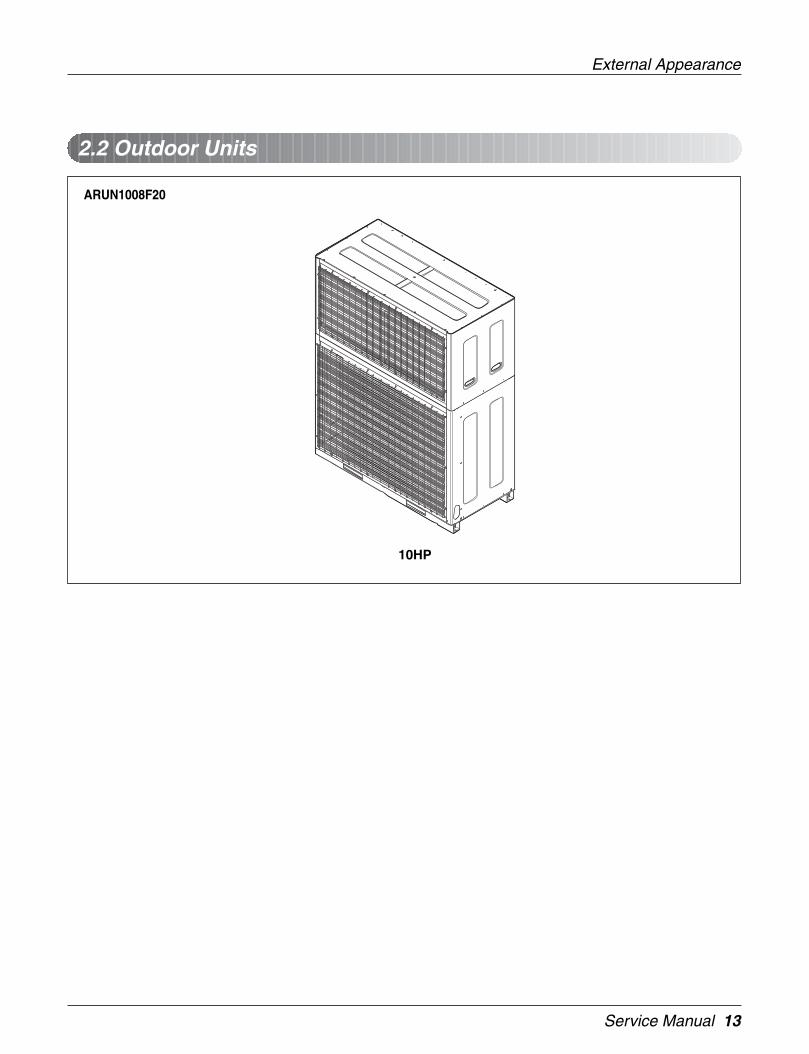
2.2 Outdoor Units
ARUN1008F20
10HP
14
Nomenclature
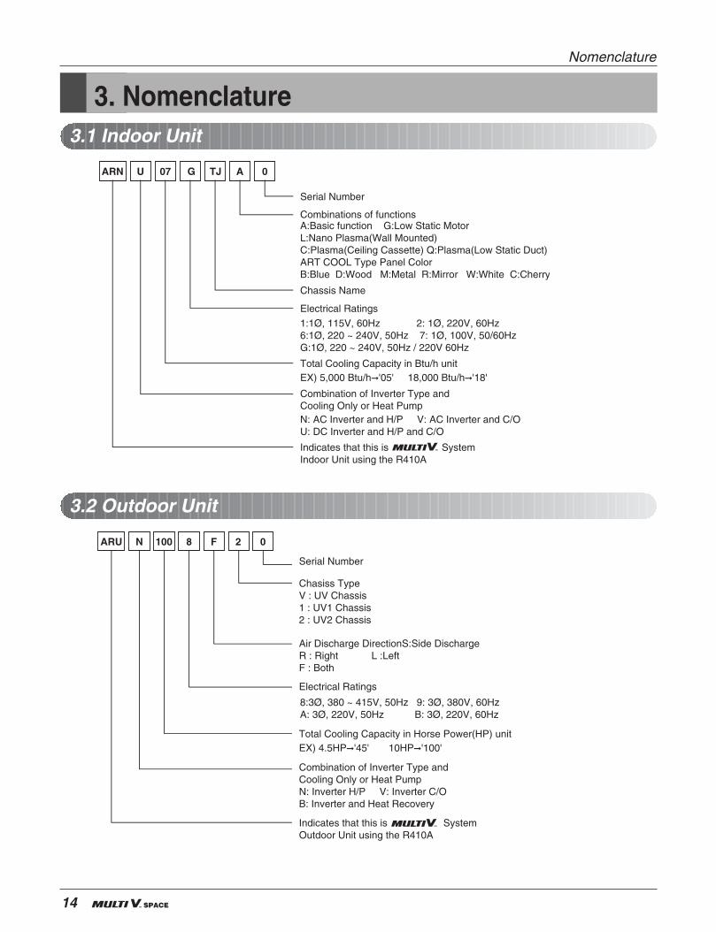
3. Nomenclature3.1 Indoor Unit
3.2 Outdoor Unit
ARN U G07 ATJ 0
Serial Number
Chassis Name
Electrical Ratings
1:1Ø, 115V, 60Hz 2: 1Ø, 220V, 60Hz6:1Ø, 220 ~ 240V, 50Hz 7: 1Ø, 100V, 50/60HzG:1Ø, 220 ~ 240V, 50Hz / 220V 60Hz
Total Cooling Capacity in Btu/h unit EX) 5,000 Btu/h'05' 18,000 Btu/h'18'
Combination of Inverter Type and Cooling Only or Heat PumpN: AC Inverter and H/P V: AC Inverter and C/OU: DC Inverter and H/P and C/O
Indicates that this is System Indoor Unit using the R410A
Combinations of functionsA:Basic function G:Low Static MotorL:Nano Plasma(Wall Mounted)C:Plasma(Ceiling Cassette) Q:Plasma(Low Static Duct)ART COOL Type Panel ColorB:Blue D:Wood M:Metal R:Mirror W:White C:Cherry
ARU N 8100 F 2 0
Chasiss TypeV : UV Chassis1 : UV1 Chassis2 : UV2 Chassis
Serial Number
Air Discharge DirectionS:Side Discharge R : Right L :LeftF : Both
Electrical Ratings
8:3Ø, 380 ~ 415V, 50Hz 9: 3Ø, 380V, 60HzA: 3Ø, 220V, 50Hz B: 3Ø, 220V, 60Hz
Total Cooling Capacity in Horse Power(HP) unit EX) 4.5HP'45' 10HP'100'
Combination of Inverter Type and Cooling Only or Heat PumpN: Inverter H/P V: Inverter C/OB: Inverter and Heat Recovery
Indicates that this is System Outdoor Unit using the R410A
Service Manual 15
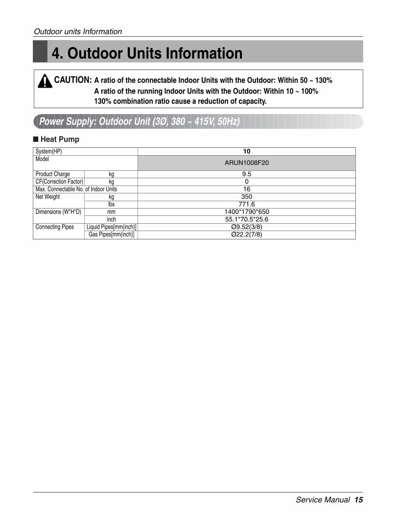
4. Outdoor Units Information
Outdoor units Information
CAUTION: A ratio of the connectable Indoor Units with the Outdoor: Within 50 ~ 130%A ratio of the running Indoor Units with the Outdoor: Within 10 ~ 100%130% combination ratio cause a reduction of capacity.
Power Supply: Outdoor Unit (3Ø, 380 ~ 415V, 50Hz)
Heat PumpSystem(HP)Model
Product Charge kgCF(Correction Factor) kgMax. Connectable No. of Indoor UnitsNet Weight kg
lbsDimensions (W*H*D) mm
inchConnecting Pipes Liquid Pipes[mm(inch)]
Gas Pipes[mm(inch)]
10
ARUN1008F20
9.5016350
771.61400*1790*65055.1*70.5*25.6
Ø9.52(3/8)Ø22.2(7/8)
16

Service Manual 17
Indoor Units
18 Indoor Unit

Service Manual 19
1. Specifications .............................................................................20
2. Functions ....................................................................................23
3. Operation Details........................................................................24
4. Dimensions .................................................................................26
5. Piping Diagrams .........................................................................28
6. Wiring Diagrams.........................................................................29
Ceiling Mounted Cassette Type (4Way)
20 Indoor Unit
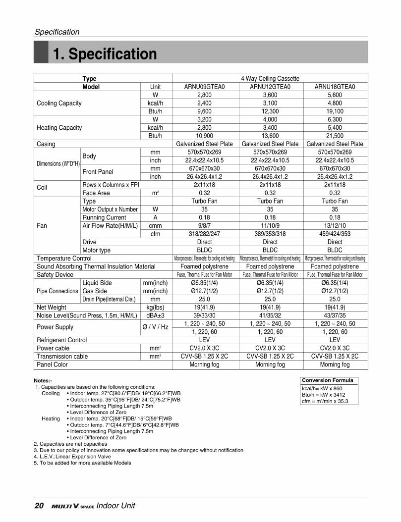
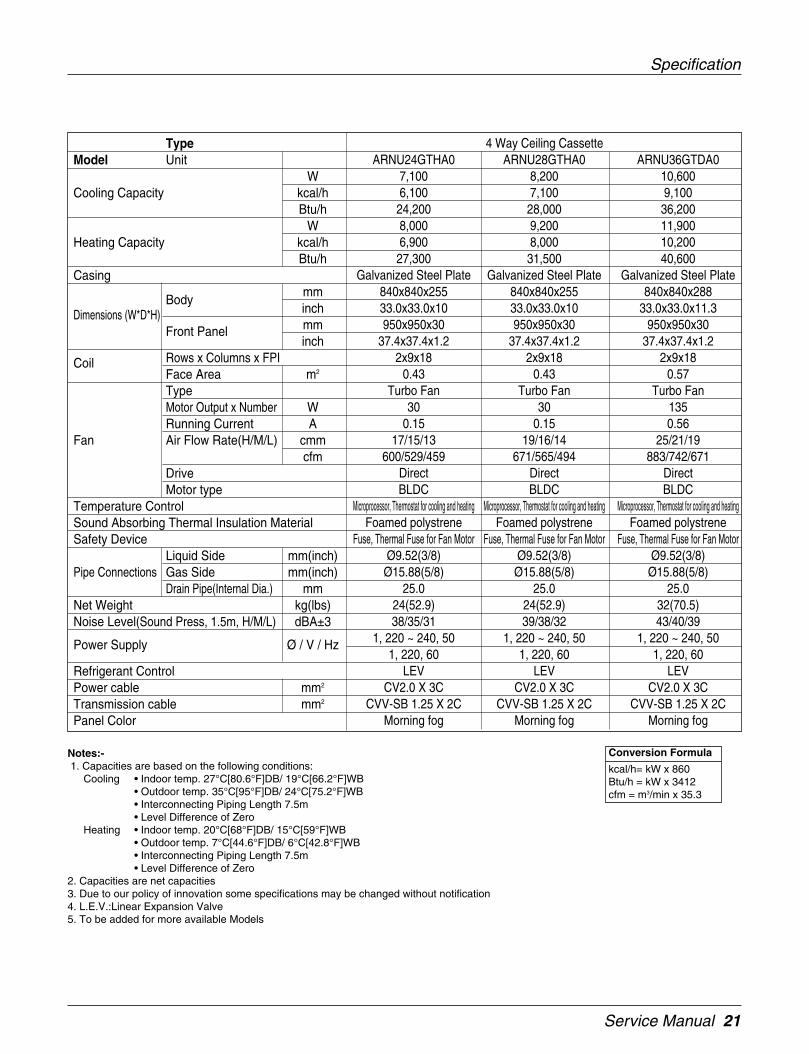
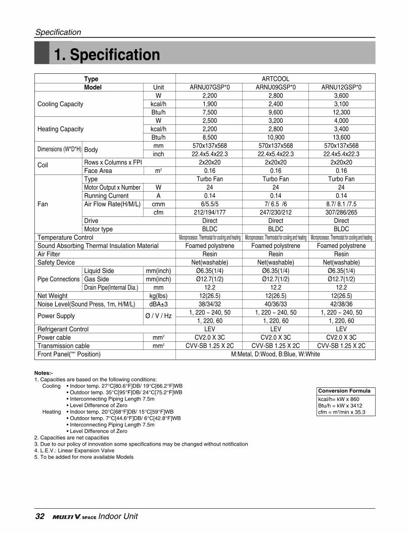
1. Specification
Specification
Notes:-1. Capacities are based on the following conditions:
Cooling • Indoor temp. 27°C[80.6°F]DB/ 19°C[66.2°F]WB• Outdoor temp. 35°C[95°F]DB/ 24°C[75.2°F]WB• Interconnecting Piping Length 7.5m• Level Difference of Zero
Heating • Indoor temp. 20°C[68°F]DB/ 15°C[59°F]WB• Outdoor temp. 7°C[44.6°F]DB/ 6°C[42.8°F]WB• Interconnecting Piping Length 7.5m• Level Difference of Zero
2. Capacities are net capacities3. Due to our policy of innovation some specifications may be changed without notification4. L.E.V.:Linear Expansion Valve5. To be added for more available Models
Conversion Formula
kcal/h= kW x 860Btu/h = kW x 3412cfm = m3/min x 35.3
TypeModel Unit
WCooling Capacity kcal/h
Btu/hW
Heating Capacity kcal/hBtu/h
Casing
Bodymm
Dimensions (W*D*H) inch
Front Panel mminch
Coil Rows x Columns x FPIFace Area m2
TypeMotor Output x Number WRunning Current A
Fan Air Flow Rate(H/M/L) cmmcfm
DriveMotor type
Temperature ControlSound Absorbing Thermal Insulation MaterialSafety Device
Liquid Side mm(inch)Pipe Connections Gas Side mm(inch)
Drain Pipe(Internal Dia.) mmNet Weight kg(lbs)Noise Level(Sound Press, 1.5m, H/M/L) dBA±3
Power Supply Ø / V / Hz
Refrigerant ControlPower cable mm2
Transmission cable mm2
Panel Color
4 Way Ceiling CassetteARNU09GTEA0 ARNU12GTEA0 ARNU18GTEA0
2,800 3,600 5,6002,400 3,100 4,8009,600 12,300 19,1003,200 4,000 6,3002,800 3,400 5,40010,900 13,600 21,500
Galvanized Steel Plate Galvanized Steel Plate Galvanized Steel Plate570x570x269 570x570x269 570x570x269
22.4x22.4x10.5 22.4x22.4x10.5 22.4x22.4x10.5670x670x30 670x670x30 670x670x30
26.4x26.4x1.2 26.4x26.4x1.2 26.4x26.4x1.22x11x18 2x11x18 2x11x18
0.32 0.32 0.32Turbo Fan Turbo Fan Turbo Fan
35 35 350.18 0.18 0.189/8/7 11/10/9 13/12/10
318/282/247 389/353/318 459/424/353Direct Direct DirectBLDC BLDC BLDC
Microprocessor, Thermostat for cooling and heating Microprocessor, Thermostat for cooling and heating Microprocessor, Thermostat for cooling and heatingFoamed polystrene Foamed polystrene Foamed polystrene
Fuse, Thermal Fuse for Fan Motor Fuse, Thermal Fuse for Fan Motor Fuse, Thermal Fuse for Fan MotorØ6.35(1/4) Ø6.35(1/4) Ø6.35(1/4)Ø12.7(1/2) Ø12.7(1/2) Ø12.7(1/2)
25.0 25.0 25.019(41.9) 19(41.9) 19(41.9)39/33/30 41/35/32 43/37/35
1, 220 ~ 240, 50 1, 220 ~ 240, 50 1, 220 ~ 240, 501, 220, 60 1, 220, 60 1, 220, 60
LEV LEV LEVCV2.0 X 3C CV2.0 X 3C CV2.0 X 3C
CVV-SB 1.25 X 2C CVV-SB 1.25 X 2C CVV-SB 1.25 X 2CMorning fog Morning fog Morning fog
Service Manual 21
Specification
Notes:-1. Capacities are based on the following conditions:
Cooling • Indoor temp. 27°C[80.6°F]DB/ 19°C[66.2°F]WB• Outdoor temp. 35°C[95°F]DB/ 24°C[75.2°F]WB• Interconnecting Piping Length 7.5m• Level Difference of Zero
Heating • Indoor temp. 20°C[68°F]DB/ 15°C[59°F]WB• Outdoor temp. 7°C[44.6°F]DB/ 6°C[42.8°F]WB• Interconnecting Piping Length 7.5m• Level Difference of Zero
2. Capacities are net capacities3. Due to our policy of innovation some specifications may be changed without notification4. L.E.V.:Linear Expansion Valve5. To be added for more available Models
Conversion Formula
kcal/h= kW x 860Btu/h = kW x 3412cfm = m3/min x 35.3
TypeModel Unit
WCooling Capacity kcal/h
Btu/hW
Heating Capacity kcal/hBtu/h
Casing
Bodymm
Dimensions (W*D*H) inch
Front Panel mminch
Coil Rows x Columns x FPIFace Area m2
TypeMotor Output x Number WRunning Current A
Fan Air Flow Rate(H/M/L) cmmcfm
DriveMotor type
Temperature ControlSound Absorbing Thermal Insulation MaterialSafety Device
Liquid Side mm(inch)Pipe Connections Gas Side mm(inch)
Drain Pipe(Internal Dia.) mmNet Weight kg(lbs)Noise Level(Sound Press, 1.5m, H/M/L) dBA±3
Power Supply Ø / V / Hz
Refrigerant ControlPower cable mm2
Transmission cable mm2
Panel Color
4 Way Ceiling CassetteARNU24GTHA0 ARNU28GTHA0 ARNU36GTDA0
7,100 8,200 10,6006,100 7,100 9,100
24,200 28,000 36,2008,000 9,200 11,9006,900 8,000 10,200
27,300 31,500 40,600Galvanized Steel Plate Galvanized Steel Plate Galvanized Steel Plate
840x840x255 840x840x255 840x840x28833.0x33.0x10 33.0x33.0x10 33.0x33.0x11.3950x950x30 950x950x30 950x950x30
37.4x37.4x1.2 37.4x37.4x1.2 37.4x37.4x1.22x9x18 2x9x18 2x9x18
0.43 0.43 0.57Turbo Fan Turbo Fan Turbo Fan
30 30 1350.15 0.15 0.56
17/15/13 19/16/14 25/21/19600/529/459 671/565/494 883/742/671
Direct Direct DirectBLDC BLDC BLDC
Microprocessor, Thermostat for cooling and heating Microprocessor, Thermostat for cooling and heating Microprocessor, Thermostat for cooling and heatingFoamed polystrene Foamed polystrene Foamed polystrene
Fuse, Thermal Fuse for Fan Motor Fuse, Thermal Fuse for Fan Motor Fuse, Thermal Fuse for Fan MotorØ9.52(3/8) Ø9.52(3/8) Ø9.52(3/8)
Ø15.88(5/8) Ø15.88(5/8) Ø15.88(5/8)25.0 25.0 25.0
24(52.9) 24(52.9) 32(70.5)38/35/31 39/38/32 43/40/39
1, 220 ~ 240, 50 1, 220 ~ 240, 50 1, 220 ~ 240, 501, 220, 60 1, 220, 60 1, 220, 60
LEV LEV LEVCV2.0 X 3C CV2.0 X 3C CV2.0 X 3C
CVV-SB 1.25 X 2C CVV-SB 1.25 X 2C CVV-SB 1.25 X 2CMorning fog Morning fog Morning fog
22 Indoor Unit
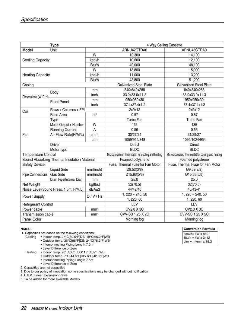
Specification
Notes:-1. Capacities are based on the following conditions:
Cooling • Indoor temp. 27°C[80.6°F]DB/ 19°C[66.2°F]WB• Outdoor temp. 35°C[95°F]DB/ 24°C[75.2°F]WB• Interconnecting Piping Length 7.5m• Level Difference of Zero
Heating • Indoor temp. 20°C[68°F]DB/ 15°C[59°F]WB• Outdoor temp. 7°C[44.6°F]DB/ 6°C[42.8°F]WB• Interconnecting Piping Length 7.5m• Level Difference of Zero
2. Capacities are net capacities3. Due to our policy of innovation some specifications may be changed without notification4. L.E.V.:Linear Expansion Valve5. To be added for more available Models
Conversion Formula
kcal/h= kW x 860Btu/h = kW x 3412cfm = m3/min x 35.3
TypeModel Unit
WCooling Capacity kcal/h
Btu/hW
Heating Capacity kcal/hBtu/h
Casing
Bodymm
Dimensions (W*D*H) inch
Front Panel mminch
Coil Rows x Columns x FPIFace Area m2
TypeMotor Output x Number WRunning Current A
Fan Air Flow Rate(H/M/L) cmmcfm
DriveMotor type
Temperature ControlSound Absorbing Thermal Insulation MaterialSafety Device
Liquid Side mm(inch)Pipe Connections Gas Side mm(inch)
Drain Pipe(Internal Dia.) mmNet Weight kg(lbs)Noise Level(Sound Press, 1.5m, H/M/L) dBA±3
Power Supply Ø / V / Hz
Refrigerant ControlPower cable mm2
Transmission cable mm2
Panel Color
4 Way Ceiling CassetteARNU42GTDA0 ARNU48GTDA0
12,300 14,10010,600 12,10042,000 48,10013,800 15,90011,000 13,20043,800 51,200
Galvanized Steel Plate Galvanized Steel Plate840x840x288 840x840x288
33.0x33.0x11.3 33.0x33.0x11.3950x950x30 950x950x30
37.4x37.4x1.2 37.4x37.4x1.22x9x12 2x9x12
0.57 0.57Turbo Fan Turbo Fan
135 1350.56 0.56
30/27/24 31/29/271059/954/848 1095/1024/954
Direct DirectBLDC BLDC
Microprocessor, Thermostat for cooling and heating Microprocessor, Thermostat for cooling and heatingFoamed polystrene Foamed polystrene
Fuse, Thermal Fuse for Fan Motor Fuse, Thermal Fuse for Fan MotorØ9.52(3/8) Ø9.52(3/8)Ø15.88(5/8) Ø15.88(5/8)
25.0 25.032(70.5) 32(70.5)44/42/40 45/43/41
1, 220 ~ 240, 50 1, 220 ~ 240, 501, 220, 60 1, 220, 60
LEV LEVCV2.0 X 3C CV2.0 X 3C
CVV-SB 1.25 X 2C CVV-SB 1.25 X 2CMorning fog Morning fog
Service Manual 23
2. Functions
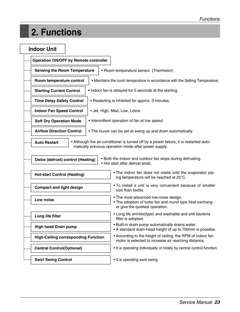
Indoor Unit
Operation ON/OFF by Remote controller
Sensing the Room Temperature
Room temperature control
Starting Current Control
Time Delay Safety Control
Indoor Fan Speed Control
Soft Dry Operation Mode
Airflow Direction Control
Deice (defrost) control (Heating)
Auto Restart
Hot-start Control (Heating) • The indoor fan does not rotate until the evaporator pip-ing temperature will be reached at 25°C.
Compact and light design • To install a unit is very convenient because of smallersize than textile.
Low noise• The most advanced low-noise design.• The adoption of turbo fan and round type heat exchang-
er give the quietest operation.
Long life filter • Long life wrinkle(type) and washable and anti-bacteriafilter is adopted.
High head Drain pump • Built-in drain pump automatically drains water.• A standard drain-head height of up to 700mm is possible.
High-Ceiling corresponding Function • According to the height of ceiling, the RPM of indoor fanmotor is selected to increase air reaching distance.
Central Control(Optional)
Swirl Swing Control
• It is operating individually or totally by central control function.
• It is operating swirl swing
• Room temperature sensor. (Thermistor)
• Maintains the room temperature in accordance with the Setting Temperature.
• Indoor fan is delayed for 5 seconds at the starting.
• Restarting is inhibited for approx. 3 minutes.
• Jet, High, Med, Low, Lolow
• Intermittent operation of fan at low speed.
• The louver can be set at swing up and down automatically.
• Although the air-conditioner is turned off by a power failure, it is restarted auto-matically previous operation mode after power supply.
• Both the indoor and outdoor fan stops during defrosting.• Hot start after defrost ends.
Functions

24 Indoor Unit
3. Operation Detail
Time Delay Safety Control• 5 sec... Vertical air flow direction control louvers open in 5 seconds to prevent noise between louvers and wind.
• 5 sec... The 4-way valve is ceased for 5 sec. to prevent the refrigerant-gas abnormal noise when the Heating
operation is OFF or switched to the other operation mode when compress is off.
While compressor is running, it takes 3~5 seconds to switch.
Auto Swing Control• This function is to swing the louver up and down automatically.
Soft-Dry Operation• The indoor fan speed is automatically set to the low, so the shift of the indoor fan speed is impossible because of
already being set to the best speed for Dry Operation by microcontroller control.
Cooling Mode Operation• When selecting the Cooling( ) Mode Operation, the unit will operate according to the setting by the remote con-
troller and the operation diagram is as following
Swirl Swing ControlVane 2, 4 is almost vane closed while vane1, 3 is opened.
Vane 1, 3 and vane 2,4 turn over minutely
Intake Air Temperature
COMP. ON(SET TEMPERATURE +0.5°C)
COMP. OFF(SET TEMPERATURE -0.5°C) More than More than
3 minutes 3 minutes
Selected Selected SelectedSpeed Speed Speed
INDOOR FAN Low Low
(1) The function of main control
Operation Detail
Vane 2
Vane 1 Vane 3
Vane 4
Service Manual 25
Intake Air temperature
Setting Temperature .+3°C(Compressor OFF)
Setting Temperature(Compressor ON)
INDOOR FAN Low OFF Low Low OFF
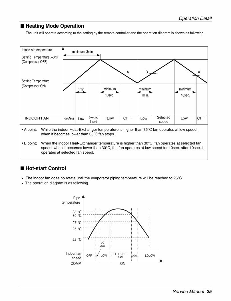
Heating Mode OperationThe unit will operate according to the setting by the remote controller and the operation diagram is shown as following.
Hot Start Low SelectedSpeed
minimum 3min
Selectedspeed
minimum
10sec.
1min
A A
minimum
1min.
minimum
10sec.
B
Hot-start Control
The indoor fan does no rotate until the evaporator piping temperature will be reached to 25°C.The operation diagram is as following.
25 °C
27 °C
35 °C30 °C
22 °C
Pipetemperature
OFFIndoor fan
speed
LOLOW
LOW SELECTEDFAN
LOW LOLOW
COMP ON
• A point; While the indoor Heat-Exchanger temperature is higher than 35°C fan operates at low speed,when it becomes lower than 35˚C fan stops.
• B point; When the indoor Heat-Exchanger temperature is higher than 30°C, fan operates at selected fanspeed, when it becomes lower than 30°C, the fan operates at low speed for 10sec, after 10sec, itoperates at selected fan speed.
Operation Detail
26 Indoor Unit
ARNU09GTEA0ARNU12GTEA0ARNU18GTEA0
269
670
30
570
269
90 90
120.
430
521
670 570
450
40
110 110
670670
4
1
3
2
5
6
Unit:mm
570 Unit size
570
Uni
t siz
e
450
(Han
ging
bol
t)75
75
600
(Cei
ling
open
ing)
600 (Ceiling opening)
521(Hanging bolt) 39.539.5
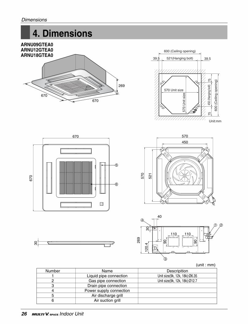
4. Dimensions
Dimensions
(unit : mm)
Number Name Descripition1 Liquid pipe connection Unit size(9k, 12k, 18k):Ø6.352 Gas pipe connection Unit size(9k, 12k, 18k):Ø12.73 Drain pipe connection4 Power supply connection5 Air discharge grill6 Air suction grill
Service Manual 27
ARNU24GTHA0ARNU28GTHA0ARNU36GTDA0ARNU38GTDA0ARNU42GTDA0ARNU48GTDA0
950950
288
47133.
4
203.
114
7
30
840 78
5
840
672
840 Unit size
840
Uni
t siz
e
672
(Han
ging
bol
t)10
1.5
101.
5 875
(Cei
ling
open
ing)
875 (Ceiling opening)
785(Hanging bolt) 4545
Unit:mm
4
1
2
950
950
5
6
255
70.4
47 84 139.
8
TDTH
3
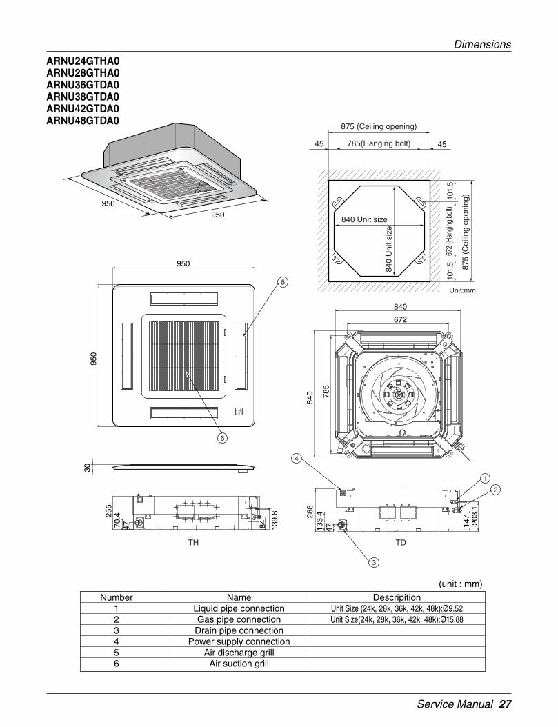
Dimensions
(unit : mm)
Number Name Descripition1 Liquid pipe connection Unit Size (24k, 28k, 36k, 42k, 48k):Ø9.522 Gas pipe connection Unit Size(24k, 28k, 36k, 42k, 48k):Ø15.883 Drain pipe connection4 Power supply connection5 Air discharge grill6 Air suction grill

28 Indoor Unit
Heat Exchanger
Turbo Fan
lndoor unit
LEV :Heating:Cooling
Filter
Filter
: Thermistor
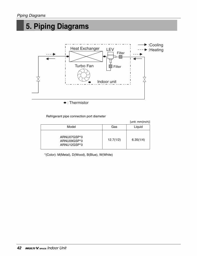
5. Piping Diagrams
Piping Diagrams
Refrigerant pipe connection port diameter
Model
ARNU09GTEA0
ARNU12GTEA0
ARNU18GTEA0
ARNU24GTHA0
ARNU28GTHA0
ARNU36GTDA0
ARNU42GTDA0
ARNU48GTDA0
Gas
Ø12.7(1/2)
Ø12.7(1/2)
Ø12.7(1/2)
Ø15.88(5/8)
Ø15.88(5/8)
Ø15.88(5/8)
Ø15.88(5/8)
Ø15.88(5/8)
Liquid
Ø6.35(1/4)
Ø6.35(1/4)
Ø6.35(1/4)
Ø9.52(3/8)
Ø9.52(3/8)
Ø9.52(3/8)
Ø9.52(3/8)
Ø9.52(3/8)
[unit: mm(inch)]
Service Manual 29
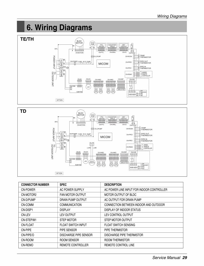
6. Wiring Diagrams
Wiring Diagrams
CONNECTOR NUMBER SPEC DESCRIPTION
CN-POWER AC POWER SUPPLY AC POWER LINE INPUT FOR INDOOR CONTROLLER
CN-MOTOR2 FAN MOTOR OUTPUT MOTOR OUTPUT OF BLDC
CN-D/PUMP DRAIN PUMP OUTPUT AC OUTPUT FOR DRAIN PUMP
CN-COMM COMMUNICATION CONNECTION BETWEEN INDOOR AND OUTDOOR
CN-DISP1 DISPLAY DISPLAY OF INDOOR STATUS
CN-LEV LEV OUTPUT LEV CONTROL OUTPUT
CN-STEP/M1 STEP MOTOR STEP MOTOR OUTPUT
CN-FLOAT FLOAT SWITCH INPUT FLOAT SWITCH SENSING
CN-PIPE PIPE SENSOR PIPE THERMISTOR
CN-PIPE/O DISCHARGE PIPE SENSOR DISCHARGE PIPE THERMISTOR
CN-ROOM ROOM SENSOR ROOM THERMISTOR
CN-REMO REMOTE CONTROLLER REMOTE CONTROL LINE
TE/TH
TD

30 Indoor Unit

Service Manual 31
1. Specification ...............................................................................32
2. Functions ....................................................................................33
3. Operation Details........................................................................34
4. Dimensions .................................................................................41
5. Piping Diagrams .........................................................................42
6. Wiring Diagrams.........................................................................43
Art Cool Type
32 Indoor Unit
1. Specification
Specification
Conversion Formula
kcal/h= kW x 860Btu/h = kW x 3412cfm = m3/min x 35.3
Notes:-1. Capacities are based on the following conditions:
Cooling • Indoor temp. 27°C[80.6°F]DB/ 19°C[66.2°F]WB• Outdoor temp. 35°C[95°F]DB/ 24°C[75.2°F]WB• Interconnecting Piping Length 7.5m• Level Difference of Zero
Heating • Indoor temp. 20°C[68°F]DB/ 15°C[59°F]WB• Outdoor temp. 7°C[44.6°F]DB/ 6°C[42.8°F]WB• Interconnecting Piping Length 7.5m• Level Difference of Zero
2. Capacities are net capacities3. Due to our policy of innovation some specifications may be changed without notification4. L.E.V.: Linear Expansion Valve5. To be added for more available Models
TypeModel Unit
WCooling Capacity kcal/h
Btu/hW
Heating Capacity kcal/hBtu/h
Dimensions (W*D*H) Bodymminch
Coil Rows x Columns x FPIFace Area m2
TypeMotor Output x Number WRunning Current A
Fan Air Flow Rate(H/M/L) cmmcfm
DriveMotor type
Temperature ControlSound Absorbing Thermal Insulation MaterialAir FilterSafety Device
Liquid Side mm(inch)Pipe Connections Gas Side mm(inch)
Drain Pipe(Internal Dia.) mmNet Weight kg(lbs)Noise Level(Sound Press, 1m, H/M/L) dBA±3
Power Supply Ø / V / Hz
Refrigerant ControlPower cable mm2
Transmission cable mm2
Front Panel('*' Position)
ARTCOOLARNU07GSP*0 ARNU09GSP*0 ARNU12GSP*0
2,200 2,800 3,6001,900 2,400 3,1007,500 9,600 12,3002,500 3,200 4,0002,200 2,800 3,4008,500 10,900 13,600
570x137x568 570x137x568 570x137x56822.4x5.4x22.3 22.4x5.4x22.3 22.4x5.4x22.3
2x20x20 2x20x20 2x20x200.16 0.16 0.16
Turbo Fan Turbo Fan Turbo Fan24 24 24
0.14 0.14 0.146/5.5/5 7/ 6.5 /6 8.7/ 8.1 /7.5
212/194/177 247/230/212 307/286/265Direct Direct DirectBLDC BLDC BLDC
Microprocessor, Thermostat for cooling and heating Microprocessor, Thermostat for cooling and heating Microprocessor, Thermostat for cooling and heatingFoamed polystrene Foamed polystrene Foamed polystrene
Resin Resin ResinNet(washable) Net(washable) Net(washable)
Ø6.35(1/4) Ø6.35(1/4) Ø6.35(1/4)Ø12.7(1/2) Ø12.7(1/2) Ø12.7(1/2)
12.2 12.2 12.212(26.5) 12(26.5) 12(26.5)38/34/32 40/36/33 42/38/36
1, 220 ~ 240, 50 1, 220 ~ 240, 50 1, 220 ~ 240, 501, 220, 60 1, 220, 60 1, 220, 60
LEV LEV LEVCV2.0 X 3C CV2.0 X 3C CV2.0 X 3C
CVV-SB 1.25 X 2C CVV-SB 1.25 X 2C CVV-SB 1.25 X 2CM:Metal, D:Wood, B:Blue, W:White

Service Manual 33
Functions
2. Functions
• Room temperature sensor. (THERMISTOR)
• Maintains the room temperature in accordance with the Setting temperature
• Indoor fan is delayed for 5 sec at the starting.
• Restarting is inhibited for approx. 3 minutes.
• High, Med, Low, CHAOS
• Intermittent operation of fan at low speed.
• The fan is switched to low(Cooling), med(Heating) speed.• The unit will be stopped after 1, 2, 3, 4, 5, 6, 7 hours.
• The fan is switched to intermittent or irregular operation• The fan speed is automatically switched from high to low speed.
• The louver can be set at the desired position or swingup and down automatically.
Indoor Unit
Operation ON/OFF by Remote controller
Sensing the Room Temperature
Room temperature control
Starting Current Control
Time Delay Safety Control
Indoor Fan Speed Control
Operation indication Lamps (LED)
Signal ReceptorReceives the signals from the remote control.(Signal receiving sound: two short beeps or one long beep.)Operation Indication Lamps
On/Off : Lights up during the system operation.Sleep Mode : Lights up during Sleep Mode Auto operation.Timer : Lights up during Timer operation.Defrost Mode : Lights up during Defrost Mode or Hot Start operation.Temperature : Indicate the setting temperature.
Soft Dry Operation Mode
• Both the indoor and outdoor fan stops dur-
ing defrosting.
• The indoor fan does not rotate until theevaporator pipe temperature will be reachedat 28°C.
Sleep Mode Auto Control
Natural Air Control by CHAOS Logic
Airflow Direction Control
Defrost(Deice) control (Heating)
Hot-start Control (Heating)
34 Indoor Unit
3. Operation Details
DISPLAY(1) High quality LCD remote controller supplied
Operation Indicator• On while in appliance operation, off while in appliance pause
Timer(on/off) and Sleep timer Indicator• On while in timer mode (on/off) and in sleep timer mode, off when timer mode is completed or canceled
Defrost Indicator• Off except when hot start during heating mode operation or while in defrost control.
Plasma Indicator• On while in plasma mode, off while plasma mode is canceled.
Auto restart• In case the power comes on again after a power failure, Auto Restarting Operation is the function to operate
procedures automatically to the previous operating conditions.If your want to use this operation, press the Auto Restart Button.
Power(Forced Operation)• Operation starts, when this button is pressed and stops when you press the button again.
Cooling Mode Operation• When the intake air temperature reaches 0.5°C below the setting temp, the compressor and the outdoor fan
stop.
• When it reaches 0.5°C above the setting temp, they start to operate again.
Compressor ON Temp=> Setting Temp+0.5°C
Compressor OFF Temp => Setting Temp-0.5°C
• While in compressor running, operating with the airflow speed set by the remote controller. While in com-pressor not running, operating with the low airflow speed regardless of the setting.
Operation Details
Function of Controls

Service Manual 35
Healthy Dehumidification Mode
• When the dehumidification operation input by the remote controller is received, the intake air temperature isdetected and the setting temp is automatically set according to the intake air temperature.
26°C ≤ Intake Air Temp => 25°C
24°C ≤ Intake Air Temp < 26°C => Intake Air Temp-1°C
18°C ≤ Intake Air Temp < 24°C => Intake Air Temp-0.5°C
Intake Air Temp < 18°C => 18°C
• While in compressor off, the indoor fan repeats low airflow speed and pause.
• While the intake air temp is between compressor on temp. and compressor off temp., 10-min dehumidificationoperation and 4-min compressor off repeat
Compressor ON Temp. => Setting Temp+0.5°C
Compressor OFF Temp. => Setting Temp-0.5°C
• In 10-min dehumidification operation, the indoor fan operates with the low airflow speed.
Heating Mode Operation
• When the intake air temp reaches +3°Cabove the setting temp, the compressor is turned off. When below thesetting temp, the compressor is turned on.
Compressor ON Temp. => Setting Temp. +2°C
Compressor OFF Temp. => Setting Temp. -4°C
• While in compressor on, the indoor fan is off when the indoor pipe temp. is below 26®¨C , when above 28°C , itoperates with the low or setting airflow speed (while in sleep mode, with the medium airflow speed).
• While in compressor off, the indoor fan is off when the indoor pipe temp is below 33°C , when above 35°C , itoperates with the low airflow speed.
• If overloaded while in heating mode operation, in order to prevent the compressor from OLP operation, the out-door fan is turned on/off according to the indoor pipe temp.
• While in defrost control, both of the indoor and outdoor fans are turned off.
Defrost Control
• While in heating mode operation in order to protect the evaporator pipe of outdoor unit from freezing, reversedto cooling cycle to defrost the evaporator pipe of the outdoor unit.
• Defrost control is available 30 minutes later since heating mode operation started, and it will not prolong over 6minutes.
• Deicing starts only when the outdoor pipe temperature falls below -6°C after 30 minutes passed from starting ofheating operating and more than 10 minutes operation of compressor.
• Deicing ends after 6 minutes passed from starting of deice operation or when the outdoor pipe temperature risesover 12°C even if before 6 minutes.
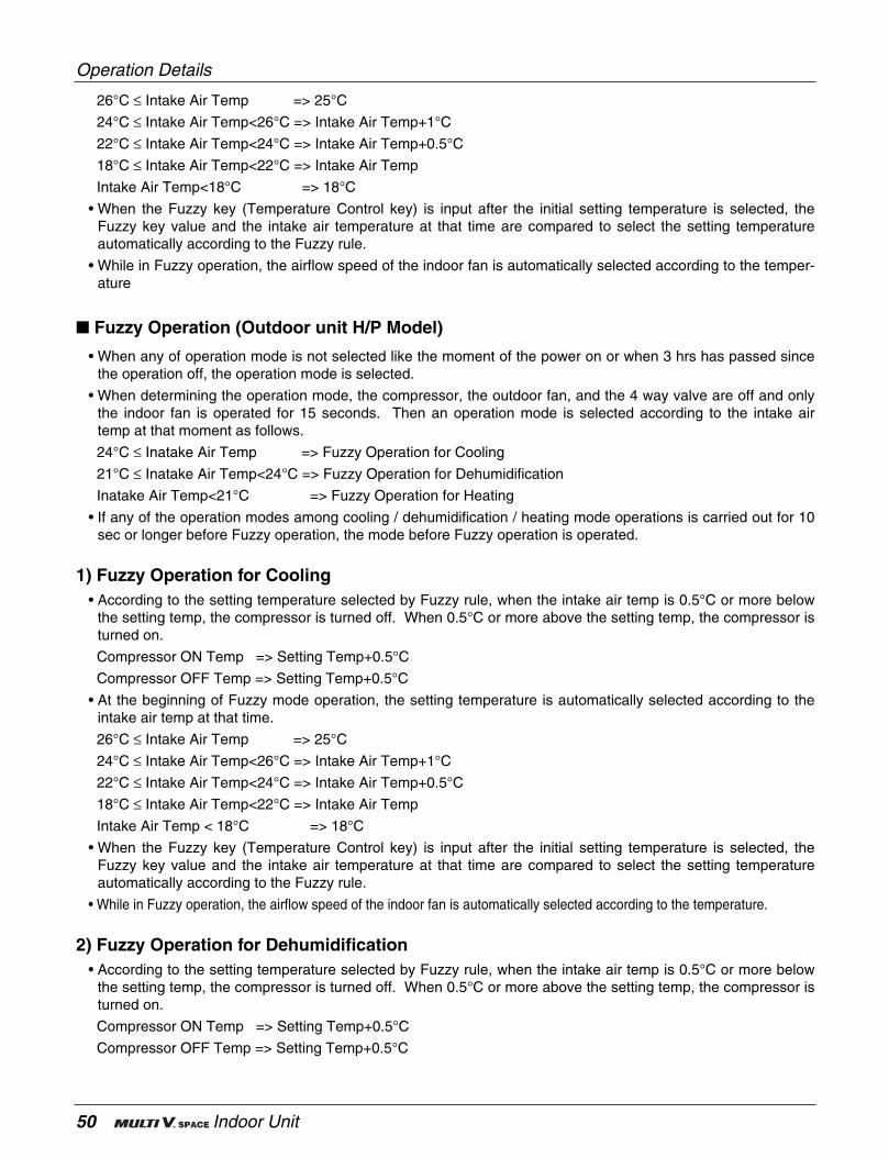
Fuzzy Operation (Outdoor unit C/O Model)
• According to the temperature set by Fuzzy rule, when the intake air temp is 0.5°C or more below the settingtemp, the compressor is turned off. When 0.5°C or more above the setting temp, the compressor is turned on.
Compressor ON Temp => Setting Temp+0.5°C
Compressor OFF Temp => Setting Temp+0.5°C
• At the beginning of Fuzzy mode operation, the setting temperature is automatically selected according to theintake air temp at that time.
Operation Details
36 Indoor Unit
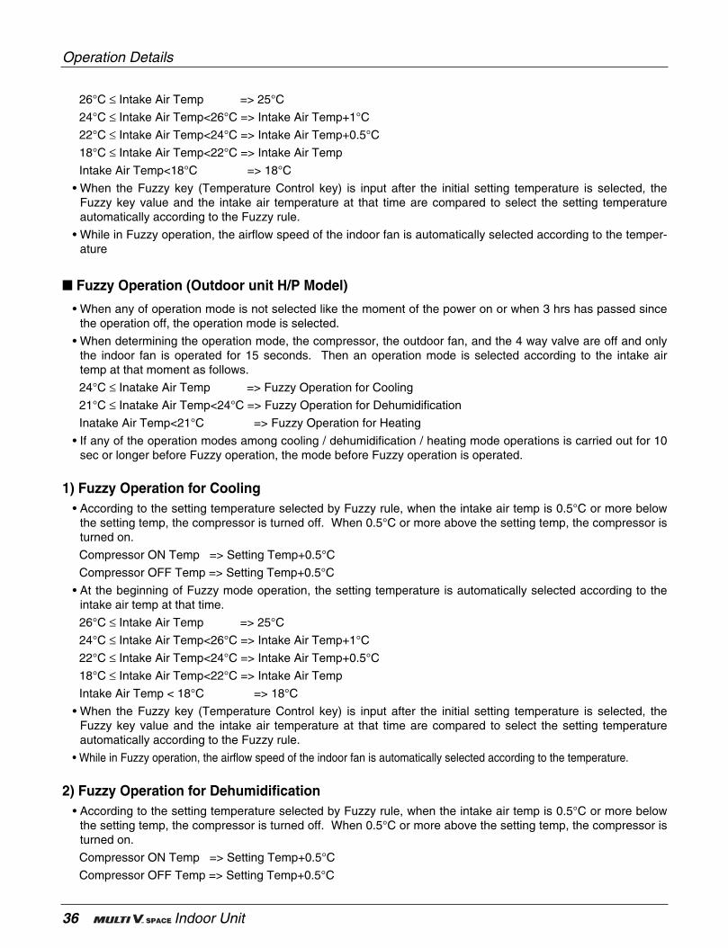
26°C ≤ Intake Air Temp => 25°C
24°C ≤ Intake Air Temp<26°C => Intake Air Temp+1°C
22°C ≤ Intake Air Temp<24°C => Intake Air Temp+0.5°C
18°C ≤ Intake Air Temp<22°C => Intake Air Temp
Intake Air Temp<18°C => 18°C
• When the Fuzzy key (Temperature Control key) is input after the initial setting temperature is selected, theFuzzy key value and the intake air temperature at that time are compared to select the setting temperatureautomatically according to the Fuzzy rule.
• While in Fuzzy operation, the airflow speed of the indoor fan is automatically selected according to the temper-ature
Fuzzy Operation (Outdoor unit H/P Model)
• When any of operation mode is not selected like the moment of the power on or when 3 hrs has passed sincethe operation off, the operation mode is selected.
• When determining the operation mode, the compressor, the outdoor fan, and the 4 way valve are off and onlythe indoor fan is operated for 15 seconds. Then an operation mode is selected according to the intake airtemp at that moment as follows.
24°C ≤ Inatake Air Temp => Fuzzy Operation for Cooling
21°C ≤ Inatake Air Temp<24°C => Fuzzy Operation for Dehumidification
Inatake Air Temp<21°C => Fuzzy Operation for Heating
• If any of the operation modes among cooling / dehumidification / heating mode operations is carried out for 10sec or longer before Fuzzy operation, the mode before Fuzzy operation is operated.
1) Fuzzy Operation for Cooling• According to the setting temperature selected by Fuzzy rule, when the intake air temp is 0.5°C or more below
the setting temp, the compressor is turned off. When 0.5°C or more above the setting temp, the compressor isturned on.
Compressor ON Temp => Setting Temp+0.5°C
Compressor OFF Temp => Setting Temp+0.5°C
• At the beginning of Fuzzy mode operation, the setting temperature is automatically selected according to theintake air temp at that time.
26°C ≤ Intake Air Temp => 25°C
24°C ≤ Intake Air Temp<26°C => Intake Air Temp+1°C
22°C ≤ Intake Air Temp<24°C => Intake Air Temp+0.5°C
18°C ≤ Intake Air Temp<22°C => Intake Air Temp
Intake Air Temp < 18°C => 18°C
• When the Fuzzy key (Temperature Control key) is input after the initial setting temperature is selected, theFuzzy key value and the intake air temperature at that time are compared to select the setting temperatureautomatically according to the Fuzzy rule.
• While in Fuzzy operation, the airflow speed of the indoor fan is automatically selected according to the temperature.
2) Fuzzy Operation for Dehumidification• According to the setting temperature selected by Fuzzy rule, when the intake air temp is 0.5°C or more below
the setting temp, the compressor is turned off. When 0.5°C or more above the setting temp, the compressor isturned on.
Compressor ON Temp => Setting Temp+0.5°C
Compressor OFF Temp => Setting Temp+0.5°C
Operation Details
Service Manual 37
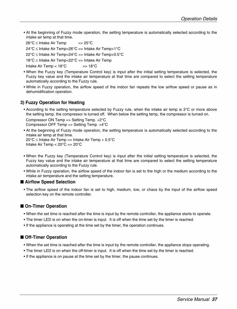
• At the beginning of Fuzzy mode operation, the setting temperature is automatically selected according to theintake air temp at that time.
26°C ≤ Intake Air Temp => 25°C
24°C ≤ Intake Air Temp<26°C => Intake Air Temp+1°C
22°C ≤ Intake Air Temp<24°C => Intake Air Temp+0.5°C
18°C ≤ Intake Air Temp<22°C => Intake Air Temp
Intake Air Temp < 18°C => 18°C
• When the Fuzzy key (Temperature Control key) is input after the initial setting temperature is selected, theFuzzy key value and the intake air temperature at that time are compared to select the setting temperatureautomatically according to the Fuzzy rule.
• While in Fuzzy operation, the airflow speed of the indoor fan repeats the low airflow speed or pause as indehumidification operation.
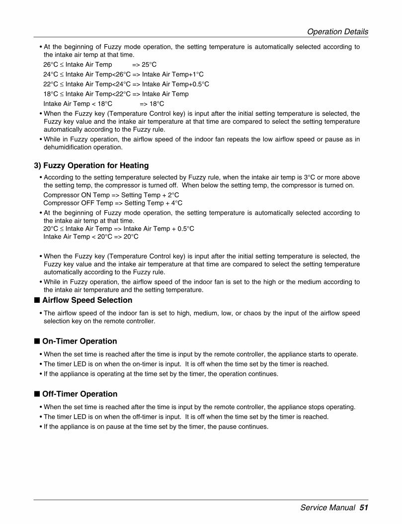
3) Fuzzy Operation for Heating• According to the setting temperature selected by Fuzzy rule, when the intake air temp is 3°C or more above
the setting temp, the compressor is turned off. When below the setting temp, the compressor is turned on.
Compressor ON Temp => Setting Temp. +2°CCompressor OFF Temp => Setting Temp. +4°C
• At the beginning of Fuzzy mode operation, the setting temperature is automatically selected according to theintake air temp at that time.20°C ≤ Intake Air Temp => Intake Air Temp + 0.5°CIntake Air Temp < 20°C => 20°C
• When the Fuzzy key (Temperature Control key) is input after the initial setting temperature is selected, theFuzzy key value and the intake air temperature at that time are compared to select the setting temperatureautomatically according to the Fuzzy rule.
• While in Fuzzy operation, the airflow speed of the indoor fan is set to the high or the medium according to theintake air temperature and the setting temperature.
Airflow Speed Selection
• The airflow speed of the indoor fan is set to high, medium, low, or chaos by the input of the airflow speedselection key on the remote controller.
On-Timer Operation
• When the set time is reached after the time is input by the remote controller, the appliance starts to operate.
• The timer LED is on when the on-timer is input. It is off when the time set by the timer is reached.
• If the appliance is operating at the time set by the timer, the operation continues.
Off-Timer Operation
• When the set time is reached after the time is input by the remote controller, the appliance stops operating.
• The timer LED is on when the off-timer is input. It is off when the time set by the timer is reached.
• If the appliance is on pause at the time set by the timer, the pause continues.
Operation Details

38 Indoor Unit
Off-Timer <=> On-Timer Operation
• When the set time is reached after the on/off time is input by the remote controller, the on/off-timer operation iscarried out according to the set time.
Sleep Timer Operation
• When the sleep time is reached after <1,2,3,4,5,6,7,0(cancel) hr> is input by the remote controller while inappliance operation, the operation of the appliance stops.
• While the appliance is on pause, the sleep timer mode cannot be input.
• While in cooling mode operation, 30 min later since the start of the sleep timer, the setting temperatureincreases by 1°C After another 30 min elapse, it increases by 1°C again.
• When the sleep timer mode is input while in cooling cycle mode, the airflow speed of the indoor fan is set tothe low.
• When the sleep timer mode is input while in heating cycle mode, the airflow speed of the indoor fan is set tothe medium.
Chaos Swing Mode• By the Chaos Swing key input, the vane automatically operates with the Chaos Swing or they are fixed to the
desired direction.
Chaos Natural Wind Mode• When the Chaos Natural Wind mode is selected and then operated, the high, medium, or low speed of the air-
flow mode is operated for 2~15 sec randomly by the Chaos Simulation.”
Jet Cool Mode Operation (Outdoor unit C/O Model)• If the Jet Cool key is input at any operation mode while in appliance operation, the Jet Cool mode operates.
• In the Jet Cool mode, the indoor fan is operated at super-high speed for 30 min at cooling mode operation.
• In the Jet Cool mode operation, the room temperature is controlled to the setting temperature, 18°C
• When the sleep timer mode is input while in the Jet Cool mode operation, the Jet Cool mode has the priority.
• During the JET COOL function at any moment, the A/C starts to blow the cool air with side louvers closed atextremely high speed for 30 minutes setting the room temp. automatically to 18°C.
Jet Cool Mode Operation (Outdoor unit H/P Model)• While in heating mode or Fuzzy operation, the Jet Cool key cannot be input. When it is input while in the other
mode operation (cooling, dehumidification, ventilation), the Jet Cool mode is operated.”
• In the Jet Cool mode, the indoor fan is operated at super-high speed for 30 min at cooling mode operation.
• In the Jet Cool mode operation, the room temperature is controlled to the setting temperature, 18°C
• When the sleep timer mode is input while in the Jet Cool mode operation, the Jet Cool mode has the priority.
• During the JET HEAT function at any moment, the A/C starts to blow the hot air with side louvers closed atextremely high speed for 60 minutes setting the room temp. automatically to 30°C.
Auto Restarting Operation• When the power is restored after a sudden power failure while in appliance operation, the mode before the
power failure is kept on the memory and the appliance automatically operates in the mode on the memory.
• Operation Mode that is kept on the memory
- State of Operation ON/OFF
Operation Details
Service Manual 39
- Operation Mode/Setting Temp/Selected Airflow Speed
- Sleep Timer Mode/Remaining Time of Sleep Timer (unit of hour)
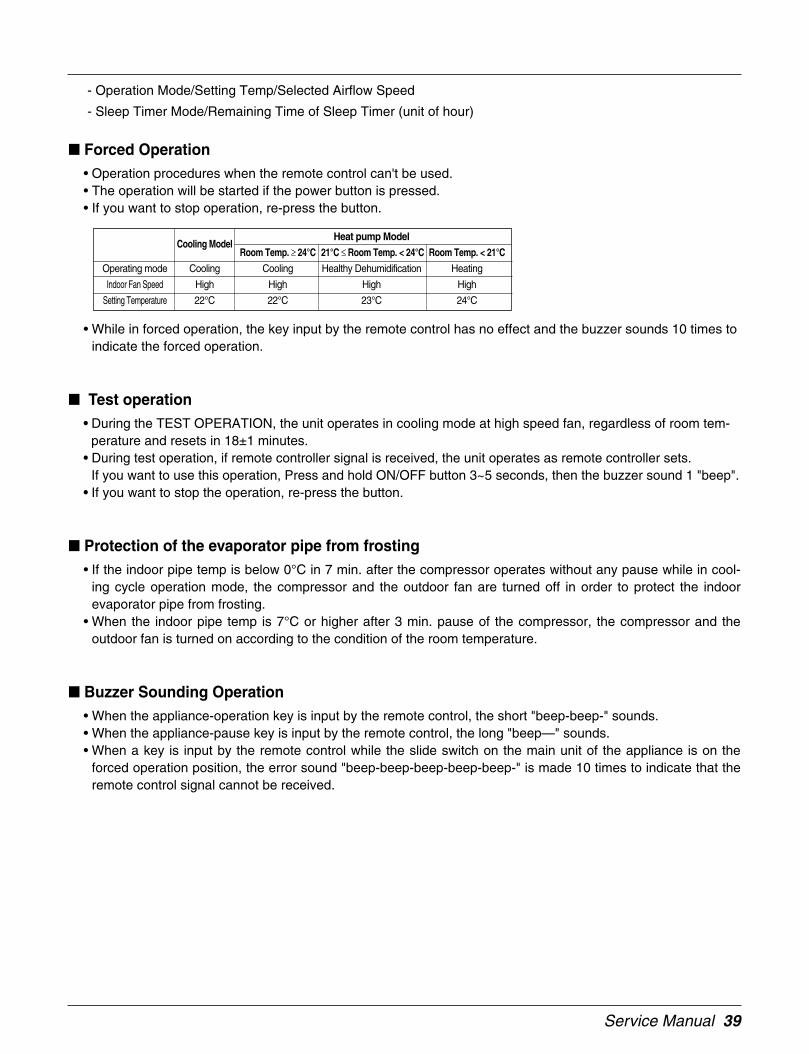
Forced Operation• Operation procedures when the remote control can't be used.• The operation will be started if the power button is pressed.• If you want to stop operation, re-press the button.
• While in forced operation, the key input by the remote control has no effect and the buzzer sounds 10 times toindicate the forced operation.
Test operation• During the TEST OPERATION, the unit operates in cooling mode at high speed fan, regardless of room tem-
perature and resets in 18±1 minutes.• During test operation, if remote controller signal is received, the unit operates as remote controller sets.
If you want to use this operation, Press and hold ON/OFF button 3~5 seconds, then the buzzer sound 1 "beep".• If you want to stop the operation, re-press the button.
Protection of the evaporator pipe from frosting• If the indoor pipe temp is below 0°C in 7 min. after the compressor operates without any pause while in cool-
ing cycle operation mode, the compressor and the outdoor fan are turned off in order to protect the indoorevaporator pipe from frosting.
• When the indoor pipe temp is 7°C or higher after 3 min. pause of the compressor, the compressor and theoutdoor fan is turned on according to the condition of the room temperature.
Buzzer Sounding Operation• When the appliance-operation key is input by the remote control, the short "beep-beep-" sounds.• When the appliance-pause key is input by the remote control, the long "beep—" sounds.• When a key is input by the remote control while the slide switch on the main unit of the appliance is on the
forced operation position, the error sound "beep-beep-beep-beep-beep-" is made 10 times to indicate that theremote control signal cannot be received.
Heat pump ModelCooling Model
Room Temp. ≥ 24°C 21°C ≤ Room Temp. < 24°C Room Temp. < 21°C
Operating mode Cooling Cooling Healthy Dehumidification Heating
Indoor Fan Speed High High High High
Setting Temperature 22°C 22°C 23°C 24°C

40 Indoor Unit
Air Cleaner Operation
• When an air cleaner function is selected during Air Conditioner operation- Plasma air cleaner function will be operated while in any operation mode with selecting the function.- The function is to be stopped while it is operating with selecting the function.
• When an air cleaner function is selected during operation off- The function will be only operated.
• When inlet grille of air conditioner is opened during plasma operation, High Voltage Generator(H.V.B) is to bestopped. When inlet grille of air conditioner is closed during plasma operation, High Voltage Generator(H.V.B)will be operated again.

Service Manual 41
4. Dimensions
Dimensions
ARNU07GSP*0ARNU09GSP*0ARNU12GSP*0
Ø 9.52Ø 6.359, 12k
GasLiquidModel
1. Pipe Specification(mm)Note:
(Unit: mm)
Pipe Hole Fix Hole
Hanger Hole
H
W D
More than 10cm
More than 50cm
More than 2m
More than 50cm
Model
ARNU07GSP*0ARNU09GSP*0ARNU12GSP*0
W
570
H
568
D
137
42 Indoor Unit
5. Piping Diagrams
Piping Diagrams
Heat Exchanger
Turbo Fan
lndoor unit
LEV :Heating:Cooling
Filter
Filter
: Thermistor
Refrigerant pipe connection port diameter
*(Color): M(Metal), D(Wood), B(Blue), W(White)
Model
ARNU07GSP*0ARNU09GSP*0ARNU12GSP*0
Gas
12.7(1/2)
Liquid
6.35(1/4)
[unit: mm(inch)]

Service Manual 43
6. Wiring Diagrams
Wirinjg Diagrams
BLDCMOTOR
CONNECTOR NUMBER SPEC DESCRIPTION
CN-POWER AC POWER SUPPLY AC POWER LINE INPUT FOR INDOOR CONTROLLER
CN-MOTOR2 FAN MOTOR OUTPUT MOTOR OUTPUT OF BLDC
CN-COM COMMUNICATION COMMUNICATION BETWEEN INDOOR AND OUTDOOR
CN-LEV LEV OUTPUT LEV CONTROL OUTPUT
CN-D1 DISPLAY DISPLAY OF INDOOR STATUS
CN-D2 DISPLAY DISPLAY OF INDOOR STATUS
CN-LR1 STEP MOTOR STEP MOTOR OUTPUT FOR LEFT/RIGHT
CN-LR2 STEP MOTOR STEP MOTOR OUTPUT FOR LEFT/RIGHT
CN-UD STEP MOTOR STEP MOTOR OUTPUT
CN-TH1 ROOM/PIPE SENSOR ROOM AND PIPE THERMISTOR
CN-TH2 DISCHARGE PIPE SENSOR DISCHARGE PIPE THERMISTOR

44 Indoor Unit
Service Manual 45
1. Specification ...............................................................................46
2. Installation...................................................................................47
3. Operation Details........................................................................48
4. Dimensions .................................................................................55
5. Piping Diagrams .........................................................................56
6. Wiring Diagrams.........................................................................57
Art Cool Type(Wide)

46 Indoor Unit
1. Specification
Specification
Notes:-1. Capacities are based on the following conditions:
Cooling • Indoor temp. 27°C[80.6°F]DB/ 19°C[66.2°F]WB• Outdoor temp. 35°C[95°F]DB/ 24°C[75.2°F]WB• Interconnecting Piping Length 7.5m• Level Difference of Zero
Heating • Indoor temp. 20°C[68°F]DB/ 15°C[59°F]WB• Outdoor temp. 7°C[44.6°F]DB/ 6°C[42.8°F]WB• Interconnecting Piping Length 7.5m• Level Difference of Zero
2. Capacities are net capacities3. Due to our policy of innovation some specifications may be changed without notification4. L.E.V.: Linear Expansion Valve5. To be added for more available Models
Conversion Formula
kcal/h= kW x 860Btu/h = kW x 3412cfm = m3/min x 35.3
TypeModel Unit
WCooling Capacity kcal/h
Btu/hW
Heating Capacity kcal/hBtu/h
Dimensions (W*D*H) Bodymminch
Coil Rows x Columns x FPIFace Area m2
TypeMotor Output x Number WRunning Current A
Fan Air Flow Rate(H/M/L) cmmcfm
DriveMotor type
Temperature ControlSound Absorbing Thermal Insulation MaterialAir FilterSafety Device
Liquid Side mm(inch)Pipe Connections Gas Side mm(inch)
Drain Pipe(Internal Dia.) mmNet Weight kg(lbs)Noise Level(Sound Press, 1m, H/M/L) dBA±3
Power Supply Ø / V / Hz
Refrigerant ControlPower cable mm2
Transmission cable mm2
Front Panel('*' Position)
ARTCOOL WideARNU18GSV*0
5,6004,80019,1006,3005,40021,500
928x147x52236.5x5.8x20.6
2x16x200.24
Turbo Fan80
0.6013.5/11.4 /10.4477/403/367.5
DirectBLDC
Microprocessor, Thermostat for cooling and heatingFoamed polystrene
ResinNet(washable)
Ø6.35(1/4)Ø12.7(1/2)
12.215(33)
44/39/341, 220 ~ 240, 50
1, 220, 60LEV
CV2.0 X 3CCVV-SB 1.25 X 2C
M:Metal, D:White, B:Blue, W:White
Service Manual 47
Functions
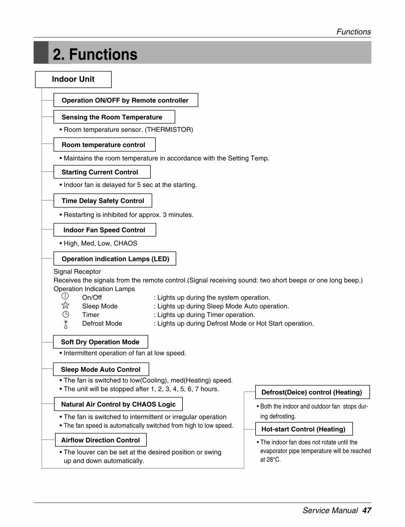
2. Functions
• Room temperature sensor. (THERMISTOR)
• Maintains the room temperature in accordance with the Setting Temp.
• Indoor fan is delayed for 5 sec at the starting.
• Restarting is inhibited for approx. 3 minutes.
• High, Med, Low, CHAOS
• Intermittent operation of fan at low speed.
• The fan is switched to low(Cooling), med(Heating) speed.• The unit will be stopped after 1, 2, 3, 4, 5, 6, 7 hours.
• The fan is switched to intermittent or irregular operation• The fan speed is automatically switched from high to low speed.
• The louver can be set at the desired position or swingup and down automatically.
Indoor Unit
Operation ON/OFF by Remote controller
Sensing the Room Temperature
Room temperature control
Starting Current Control
Time Delay Safety Control
Indoor Fan Speed Control
Operation indication Lamps (LED)
Soft Dry Operation Mode
• Both the indoor and outdoor fan stops dur-
ing defrosting.
• The indoor fan does not rotate until theevaporator pipe temperature will be reachedat 28°C.
Sleep Mode Auto Control
Natural Air Control by CHAOS Logic
Airflow Direction Control
Defrost(Deice) control (Heating)
Hot-start Control (Heating)
Signal ReceptorReceives the signals from the remote control.(Signal receiving sound: two short beeps or one long beep.)Operation Indication Lamps
On/Off : Lights up during the system operation.Sleep Mode : Lights up during Sleep Mode Auto operation.Timer : Lights up during Timer operation.Defrost Mode : Lights up during Defrost Mode or Hot Start operation.

48 Indoor Unit
3. Operation Details
DISPLAY1) High quality LCD remote controller suppliedOperation Indicator
• On while in appliance operation, off while in appliance pause
Timer Indicator• On while in timer mode (on/off) and in sleep timer mode, off when timer mode is completed or canceled
Defrost Indicator• Off except when hot start during heating mode operation or while in defrost control.
Plasma Indicator• On while in plasma mode, off while plasma mode is canceled.
Auto restart Indicator• On while auto restart mode, off while auto restart mode is canceled.
Auto restart• In case the power comes on again after a power failure, Auto Restarting Operation is the function to operate
procedures automatically to the previous operating conditions.If your want to use this operation, press the Auto Restart Button.
Power(Forced Operation)• Operation starts, when this button is pressed and stops when you press the button again.
Cooling Mode Operation• When the intake air temperature reaches 0.5°C below the setting temp, the compressor and the outdoor fan stop.
• When it reaches 0.5°C above the setting temp, they start to operate again.
Compressor ON Temp=> Setting Temp+0.5°C
Compressor OFF Temp => Setting Temp-0.5°C
• While in compressor running, operating with the airflow speed set by the remote controller. While in compres-sor not running, operating with the low airflow speed regardless of the setting.
Operation Details
Function of Controls

Service Manual 49
Healthy Dehumidification Mode
• When the dehumidification operation input by the remote controller is received, the intake air temperature isdetected and the setting temp is automatically set according to the intake air temperature.
26°C ≤ Intake Air Temp => 25°C
24°C ≤ Intake Air Temp < 26°C => Intake Air Temp-1°C
18°C ≤ Intake Air Temp < 24°C => Intake Air Temp-0.5°C
Intake Air Temp < 18°C => 18°C
• While in compressor off, the indoor fan repeats low airflow speed and pause.
• While the intake air temp is between compressor on temp. and compressor off temp., 10-min dehumidificationoperation and 4-min compressor off repeat
Compressor ON Temp. => Setting Temp+0.5°C
Compressor OFF Temp. => Setting Temp-0.5°C
• In 10-min dehumidification operation, the indoor fan operates with the low airflow speed.
Heating Mode Operation
• When the intake air temp reaches +3°Cabove the setting temp, the compressor is turned off. When below thesetting temp, the compressor is turned on.
Compressor ON Temp. => Setting Temp. +2˚C
Compressor OFF Temp. => Setting Temp.+4°C
• While in compressor on, the indoor fan is off when the indoor pipe temp. is below 26®¨C , when above 28°C ,it operates with the low or setting airflow speed (while in sleep mode, with the medium airflow speed).
• While in compressor off, the indoor fan is off when the indoor pipe temp is below 33°C , when above 35°C , itoperates with the low airflow speed.
• If overloaded while in heating mode operation, in order to prevent the compressor from OLP operation, theoutdoor fan is turned on/off according to the indoor pipe temp.
• While in defrost control, both of the indoor and outdoor fans are turned off.
Defrost Control
• While in heating mode operation in order to protect the evaporator pipe of outdoor unit from freezing, reversedto cooling cycle to defrost the evaporator pipe of the outdoor unit.
• Defrost control is available 30 minutes later since heating mode operation started, and it will not polong over 6minutes.
• Deicing starts only when the outdoor pipe temperature falls below -6°C after 30 minutes passed from starting ofheating operating and more than 10 minutes operation of compressor.
• Deicing ends after 6 minutes passed from starting of deice operation or when the outdoor pipe temperature risesover 12°C even if before 6 minutes.
Fuzzy Operation (Outdoor unit C/O Model)
• According to the temperature set by Fuzzy rule, when the intake air temp is 0.5°C or more below the settingtemp, the compressor is turned off. When 0.5°C or more above the setting temp, the compressor is turned on.
Compressor ON Temp => Setting Temp+0.5°C
Compressor OFF Temp => Setting Temp+0.5°C
• At the beginning of Fuzzy mode operation, the setting temperature is automatically selected according to theintake air temp at that time.
Operation Details
50 Indoor Unit
Operation Details
26°C ≤ Intake Air Temp => 25°C
24°C ≤ Intake Air Temp<26°C => Intake Air Temp+1°C
22°C ≤ Intake Air Temp<24°C => Intake Air Temp+0.5°C
18°C ≤ Intake Air Temp<22°C => Intake Air Temp
Intake Air Temp<18°C => 18°C
• When the Fuzzy key (Temperature Control key) is input after the initial setting temperature is selected, theFuzzy key value and the intake air temperature at that time are compared to select the setting temperatureautomatically according to the Fuzzy rule.
• While in Fuzzy operation, the airflow speed of the indoor fan is automatically selected according to the temper-ature
Fuzzy Operation (Outdoor unit H/P Model)
• When any of operation mode is not selected like the moment of the power on or when 3 hrs has passed sincethe operation off, the operation mode is selected.
• When determining the operation mode, the compressor, the outdoor fan, and the 4 way valve are off and onlythe indoor fan is operated for 15 seconds. Then an operation mode is selected according to the intake airtemp at that moment as follows.
24°C ≤ Inatake Air Temp => Fuzzy Operation for Cooling
21°C ≤ Inatake Air Temp<24°C => Fuzzy Operation for Dehumidification
Inatake Air Temp<21°C => Fuzzy Operation for Heating
• If any of the operation modes among cooling / dehumidification / heating mode operations is carried out for 10sec or longer before Fuzzy operation, the mode before Fuzzy operation is operated.
1) Fuzzy Operation for Cooling• According to the setting temperature selected by Fuzzy rule, when the intake air temp is 0.5°C or more below
the setting temp, the compressor is turned off. When 0.5°C or more above the setting temp, the compressor isturned on.
Compressor ON Temp => Setting Temp+0.5°C
Compressor OFF Temp => Setting Temp+0.5°C
• At the beginning of Fuzzy mode operation, the setting temperature is automatically selected according to theintake air temp at that time.
26°C ≤ Intake Air Temp => 25°C
24°C ≤ Intake Air Temp<26°C => Intake Air Temp+1°C
22°C ≤ Intake Air Temp<24°C => Intake Air Temp+0.5°C
18°C ≤ Intake Air Temp<22°C => Intake Air Temp
Intake Air Temp < 18°C => 18°C
• When the Fuzzy key (Temperature Control key) is input after the initial setting temperature is selected, theFuzzy key value and the intake air temperature at that time are compared to select the setting temperatureautomatically according to the Fuzzy rule.
• While in Fuzzy operation, the airflow speed of the indoor fan is automatically selected according to the temperature.
2) Fuzzy Operation for Dehumidification• According to the setting temperature selected by Fuzzy rule, when the intake air temp is 0.5°C or more below
the setting temp, the compressor is turned off. When 0.5°C or more above the setting temp, the compressor isturned on.
Compressor ON Temp => Setting Temp+0.5°C
Compressor OFF Temp => Setting Temp+0.5°C
Service Manual 51
Operation Details
• At the beginning of Fuzzy mode operation, the setting temperature is automatically selected according tothe intake air temp at that time.
26°C ≤ Intake Air Temp => 25°C
24°C ≤ Intake Air Temp<26°C => Intake Air Temp+1°C
22°C ≤ Intake Air Temp<24°C => Intake Air Temp+0.5°C
18°C ≤ Intake Air Temp<22°C => Intake Air Temp
Intake Air Temp < 18°C => 18°C
• When the Fuzzy key (Temperature Control key) is input after the initial setting temperature is selected, theFuzzy key value and the intake air temperature at that time are compared to select the setting temperatureautomatically according to the Fuzzy rule.
• While in Fuzzy operation, the airflow speed of the indoor fan repeats the low airflow speed or pause as indehumidification operation.
3) Fuzzy Operation for Heating• According to the setting temperature selected by Fuzzy rule, when the intake air temp is 3°C or more above
the setting temp, the compressor is turned off. When below the setting temp, the compressor is turned on.
Compressor ON Temp => Setting Temp + 2°CCompressor OFF Temp => Setting Temp + 4°C
• At the beginning of Fuzzy mode operation, the setting temperature is automatically selected according tothe intake air temp at that time.20°C ≤ Intake Air Temp => Intake Air Temp + 0.5°CIntake Air Temp < 20°C => 20°C
• When the Fuzzy key (Temperature Control key) is input after the initial setting temperature is selected, theFuzzy key value and the intake air temperature at that time are compared to select the setting temperatureautomatically according to the Fuzzy rule.
• While in Fuzzy operation, the airflow speed of the indoor fan is set to the high or the medium according tothe intake air temperature and the setting temperature.
Airflow Speed Selection
• The airflow speed of the indoor fan is set to high, medium, low, or chaos by the input of the airflow speedselection key on the remote controller.
On-Timer Operation
• When the set time is reached after the time is input by the remote controller, the appliance starts to operate.
• The timer LED is on when the on-timer is input. It is off when the time set by the timer is reached.
• If the appliance is operating at the time set by the timer, the operation continues.
Off-Timer Operation
• When the set time is reached after the time is input by the remote controller, the appliance stops operating.
• The timer LED is on when the off-timer is input. It is off when the time set by the timer is reached.
• If the appliance is on pause at the time set by the timer, the pause continues.
52 Indoor Unit
Operation Details
Off-Timer <=> On-Timer Operation
• When the set time is reached after the on/off time is input by the remote controller, the on/off-timer operationis carried out according to the set time.
Sleep Timer Operation
• When the sleep time is reached after <1,2,3,4,5,6,7,0(cancel) hr> is input by the remote controller while inappliance operation, the operation of the appliance stops.
• While the appliance is on pause, the sleep timer mode cannot be input.
• While in cooling mode operation, 30 min later since the start of the sleep timer, the setting temperatureincreases by 1°C After another 30 min elapse, it increases by 1°C again.
• When the sleep timer mode is input while in cooling cycle mode, the airflow speed of the indoor fan is set tothe low.
• When the sleep timer mode is input while in heating cycle mode, the airflow speed of the indoor fan is set tothe medium.
Chaos Swing Mode• By the Chaos Swing key input, the vane automatically operates with the Chaos Swing or they are fixed to the
desired direction.
Chaos Natural Wind Mode• When the Chaos Natural Wind mode is selected and then operated, the high, medium, or low speed of the air-
flow mode is operated for 2~15 sec randomly by the Chaos Simulation.”
Jet Cool Mode Operation (Outdoor unit C/O Model)• If the Jet Cool key is input at any operation mode while in appliance operation, the Jet Cool mode operates.
• In the Jet Cool mode, the indoor fan is operated at super-high speed for 30 min at cooling mode operation.
• In the Jet Cool mode operation, the room temperature is controlled to the setting temperature, 18°C
• When the sleep timer mode is input while in the Jet Cool mode operation, the Jet Cool mode has the priority.
• When the Jet Cool key is input, the upper/lower vanes are reset to those of the initial cooling mode and thenoperated in order that the air outflow could reach further.
Jet Cool Mode Operation (Outdoor unit H/P Model)• While in heating mode or Fuzzy operation, the Jet Cool key cannot be input. When it is input while in the
other mode operation (cooling, dehumidification, ventilation), the Jet Cool mode is operated.”
• In the Jet Cool mode, the indoor fan is operated at super-high speed for 30 min at cooling mode operation.
• In the Jet Cool mode operation, the room temperature is controlled to the setting temperature, 18°C
• When the sleep timer mode is input while in the Jet Cool mode operation, the Jet Cool mode has the priority.
• When the Jet Cool key is input, the upper/lower vanes are reset to those of the initial cooling mode and thenoperated in order that the air outflow could reach further.
Auto Restarting Operation• When the power is restored after a sudden power failure while in appliance operation, the mode before the
power failure is kept on the memory and the appliance automatically operates in the mode on the memory.
• Operation Mode that is kept on the memory

Service Manual 53
Operation Details
- State of Operation ON/OFF
- Operation Mode/Setting Temp/Selected Airflow Speed
- Sleep Timer Mode/Remaining Time of Sleep Timer (unit of hour)
Forced Operation (Outdoor unit C/O Model)
• To operate the appliance by force in case that the remote controller is lost, the forced operation button is onthe main unit of the appliance to operate the appliance in the standard conditions.
• Press the forced operation button, the forced operation is carried out.
• Press the forced operation button once again to stop operation.
• The forced operation is carried out in cooling mode with the setting temperature 22°C and the high speed ofairflow.
Forced Operation (Outdoor unit H/P Model)
• To operate the appliance by force in case that the remote controller is lost, the forced operation selectionswitch is on the main unit of the appliance to operate the appliance in the standard conditions.
• Press the forced operation button, the forced operation is carried out.
• Press the forced operation button once again to stop operation.
• In the forced operation mode, the indoor fan is operated at low speed for around 15 sec and then the operationcondition is set according to the intake air temperature as follows.
24°C ≤ Intake Air Temp => Cooling Mode Operation, 22°C, High Speed
21°C ≤ Intake Air Temp < 24°C => Dehumidification Operation, 23°C, High Speed
Intake Air Temp < 21°C => Heating Mode Operation, 24°C, High Speed
Test Operation Control
• To check the condition of the installation when installing the appliance, the appliance is operated at coolingmode, high speed of airflow, compressor-on for 18 min without controlling the room temperature.
• After supplying power to the main body, keep pressing the forced operation button for about 3 seconds.
• While in test operation, a key can be input by the remote controller.When a key (operation start/stop, operation mode selection, airflow speed selection, temperature control, JetCool) is input by the remote controller, the test operation is canceled and the appliance is operated accordingto the setting by the remote controller.
Protection of the evaporator pipe from frosting
• In the temperrature of the indoor pipe is below 0°C after 7 minutes from starting the compressor, the compres-sor and outdoor fan are stopped, and 3 minutes delay of operating of the compressor, when the temperature ofthe indoor pipe is over 7°C, the compressor and the outdoor fan are reoperated.
• Outdoor fan motor stops when indoor pipe temperature is blow 3°C and restarts at the pipe temperature above6°C or after 90 seconds, if the pipe temperature does not rise to 6°C, outdoor fan motor runs continuously ateven below 3°C.
54 Indoor Unit
Operation Details
Buzzer Sounding Operation
• When the appliance-operation key is input by the remote controller, the short “beep-beep-” sounds.
• When the appliance-pause key is input by the remote controller, the long “beep—” sounds.
Air Cleaner Operation
• When an air cleaner function is selected during Air Conditioner operation- Plasma air cleaner function will be operated while in any operation mode with selecting the function.- The function is to be stopped while it is operating with selecting the function.
• When an air cleaner function is selected during operation off- The function will be only operated.
• When inlet grille of air conditioner is opened during plasma operation, High Voltage Generator(H.V.B) is to bestopped. When inlet grille of air conditioner is closed during plasma operation, High Voltage Generator(H.V.B)will be operated again.

Service Manual 55
Dimensions
4. DimensionsARNU18GSV*0
H
W D
Pipe Hole Pipe Hole
240m
m
60mm
240m
m
60mm
More than 10cm
More than50cm
More than 2m
More than50cm
Model
ARNU18GSV*0
W
928
H
522
D
147
(Unit: mm)
56 Indoor Unit
Piping Diagrams
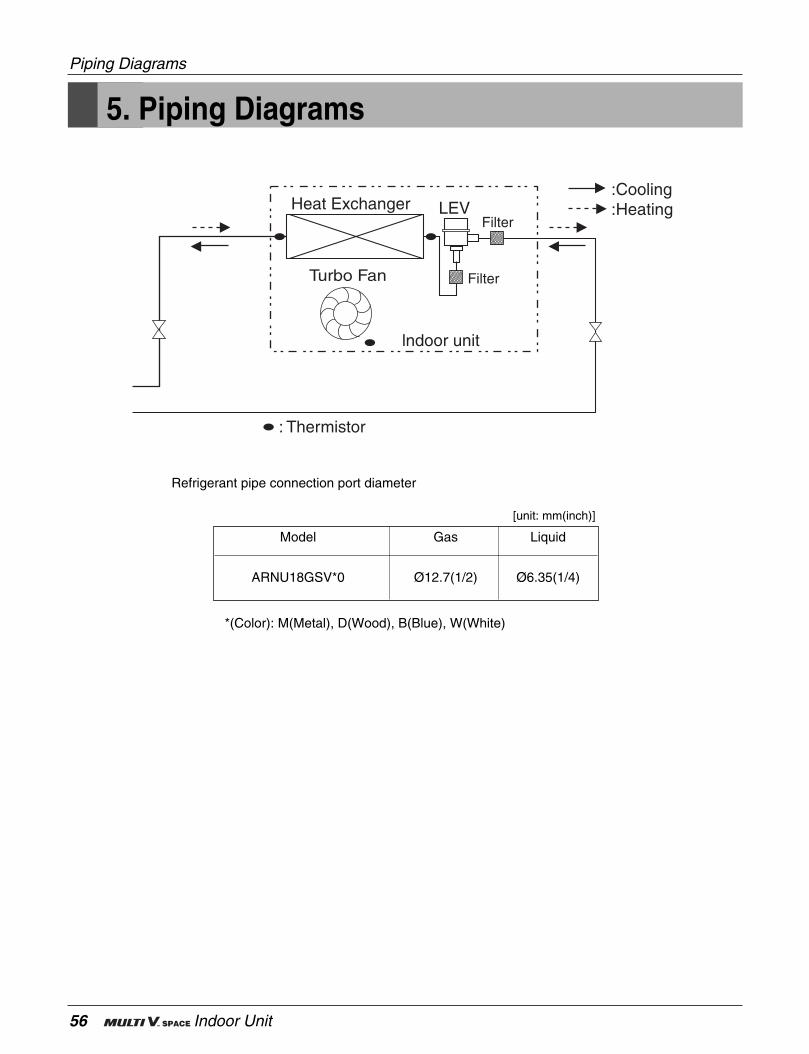
5. Piping Diagrams
Heat Exchanger
Turbo Fan
lndoor unit
LEV :Heating:Cooling
Filter
Filter
: Thermistor
Refrigerant pipe connection port diameter
*(Color): M(Metal), D(Wood), B(Blue), W(White)
Model Gas Liquid
ARNU18GSV*0 Ø12.7(1/2) Ø6.35(1/4)
[unit: mm(inch)]
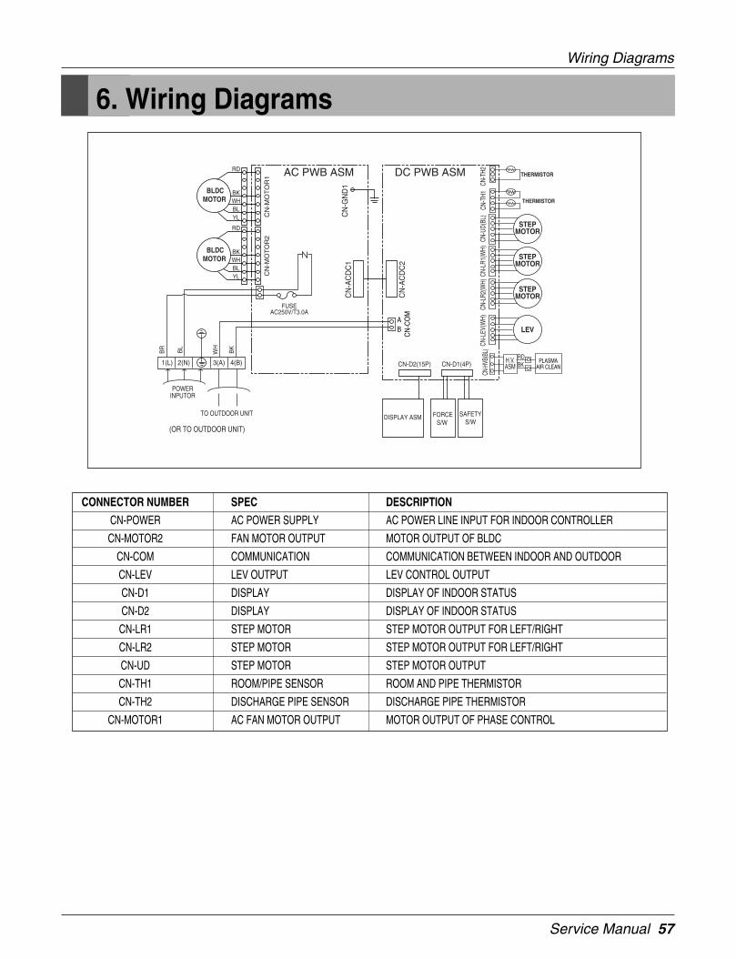
Service Manual 57
Wiring Diagrams
6. Wiring Diagrams
FORCES/W
DISPLAY ASM SAFETYS/W
CN-D2(15P) CN-D1(4P)
BLDCMOTOR
BLDCMOTOR
CONNECTOR NUMBER SPEC DESCRIPTION
CN-POWER AC POWER SUPPLY AC POWER LINE INPUT FOR INDOOR CONTROLLER
CN-MOTOR2 FAN MOTOR OUTPUT MOTOR OUTPUT OF BLDC
CN-COM COMMUNICATION COMMUNICATION BETWEEN INDOOR AND OUTDOOR
CN-LEV LEV OUTPUT LEV CONTROL OUTPUT
CN-D1 DISPLAY DISPLAY OF INDOOR STATUS
CN-D2 DISPLAY DISPLAY OF INDOOR STATUS
CN-LR1 STEP MOTOR STEP MOTOR OUTPUT FOR LEFT/RIGHT
CN-LR2 STEP MOTOR STEP MOTOR OUTPUT FOR LEFT/RIGHT
CN-UD STEP MOTOR STEP MOTOR OUTPUT
CN-TH1 ROOM/PIPE SENSOR ROOM AND PIPE THERMISTOR
CN-TH2 DISCHARGE PIPE SENSOR DISCHARGE PIPE THERMISTOR
CN-MOTOR1 AC FAN MOTOR OUTPUT MOTOR OUTPUT OF PHASE CONTROL

58 Indoor Unit
1. Specifications .............................................................................59
2. Funtion ........................................................................................61
3. Operation Details........................................................................62
4. Dimensions .................................................................................65
5. Piping Diagrams .........................................................................66
6. Wiring Diagrams.........................................................................67
Ceiling Concealed Duct Type (Low static)
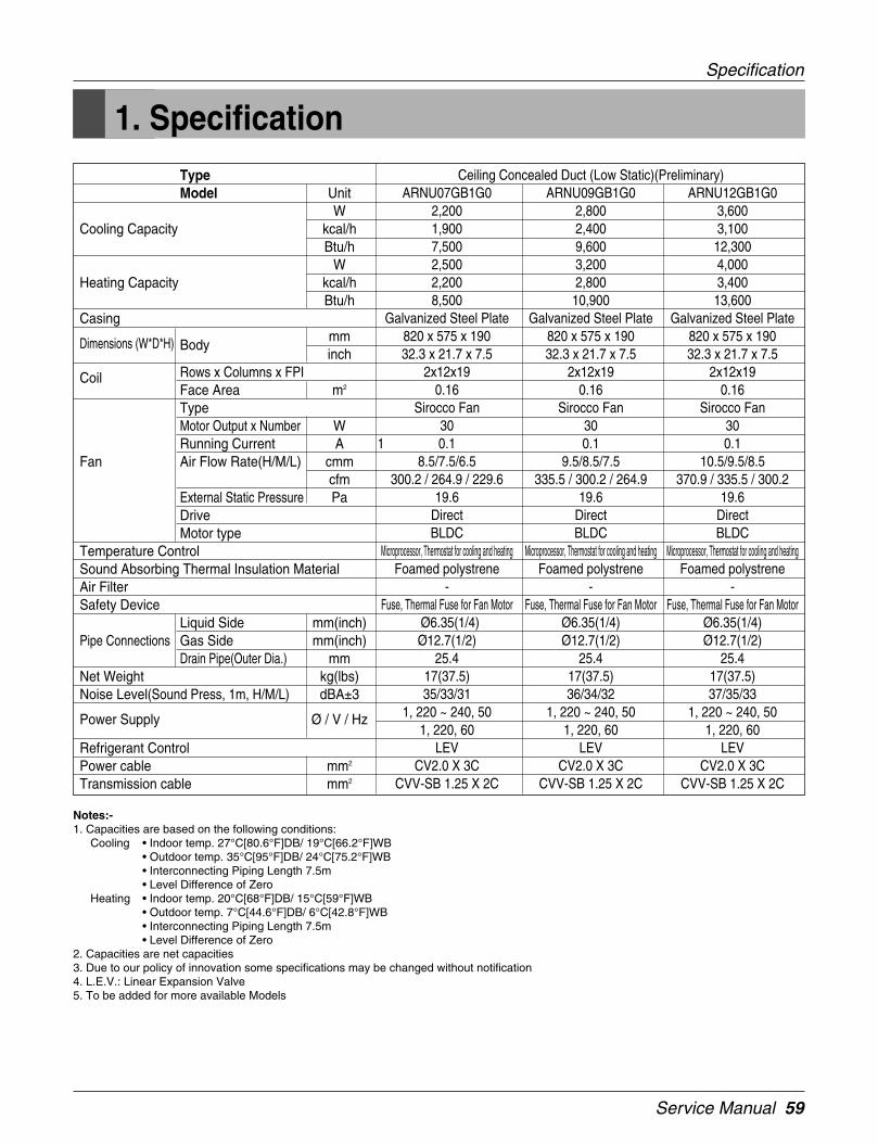
Service Manual 59
1. Specification
Specification
Notes:-1. Capacities are based on the following conditions:
Cooling • Indoor temp. 27°C[80.6°F]DB/ 19°C[66.2°F]WB• Outdoor temp. 35°C[95°F]DB/ 24°C[75.2°F]WB• Interconnecting Piping Length 7.5m• Level Difference of Zero
Heating • Indoor temp. 20°C[68°F]DB/ 15°C[59°F]WB• Outdoor temp. 7°C[44.6°F]DB/ 6°C[42.8°F]WB• Interconnecting Piping Length 7.5m• Level Difference of Zero
2. Capacities are net capacities3. Due to our policy of innovation some specifications may be changed without notification4. L.E.V.: Linear Expansion Valve5. To be added for more available Models
TypeModel Unit
WCooling Capacity kcal/h
Btu/hW
Heating Capacity kcal/hBtu/h
Casing
Dimensions (W*D*H) Bodymminch
Coil Rows x Columns x FPIFace Area m2
TypeMotor Output x Number WRunning Current A
Fan Air Flow Rate(H/M/L) cmmcfm
External Static Pressure PaDriveMotor type
Temperature ControlSound Absorbing Thermal Insulation MaterialAir FilterSafety Device
Liquid Side mm(inch)Pipe Connections Gas Side mm(inch)
Drain Pipe(Outer Dia.) mmNet Weight kg(lbs)Noise Level(Sound Press, 1m, H/M/L) dBA±3
Power Supply Ø / V / Hz
Refrigerant ControlPower cable mm2
Transmission cable mm2
Ceiling Concealed Duct (Low Static)(Preliminary)ARNU07GB1G0 ARNU09GB1G0 ARNU12GB1G0
2,200 2,800 3,6001,900 2,400 3,1007,500 9,600 12,3002,500 3,200 4,0002,200 2,800 3,4008,500 10,900 13,600
Galvanized Steel Plate Galvanized Steel Plate Galvanized Steel Plate820 x 575 x 190 820 x 575 x 190 820 x 575 x 19032.3 x 21.7 x 7.5 32.3 x 21.7 x 7.5 32.3 x 21.7 x 7.5
2x12x19 2x12x19 2x12x190.16 0.16 0.16
Sirocco Fan Sirocco Fan Sirocco Fan30 30 30
1 0.1 0.1 0.18.5/7.5/6.5 9.5/8.5/7.5 10.5/9.5/8.5
300.2 / 264.9 / 229.6 335.5 / 300.2 / 264.9 370.9 / 335.5 / 300.219.6 19.6 19.6
Direct Direct DirectBLDC BLDC BLDC
Microprocessor, Thermostat for cooling and heating Microprocessor, Thermostat for cooling and heating Microprocessor, Thermostat for cooling and heatingFoamed polystrene Foamed polystrene Foamed polystrene
- - -Fuse, Thermal Fuse for Fan Motor Fuse, Thermal Fuse for Fan Motor Fuse, Thermal Fuse for Fan Motor
Ø6.35(1/4) Ø6.35(1/4) Ø6.35(1/4)Ø12.7(1/2) Ø12.7(1/2) Ø12.7(1/2)
25.4 25.4 25.417(37.5) 17(37.5) 17(37.5)35/33/31 36/34/32 37/35/33
1, 220 ~ 240, 50 1, 220 ~ 240, 50 1, 220 ~ 240, 501, 220, 60 1, 220, 60 1, 220, 60
LEV LEV LEVCV2.0 X 3C CV2.0 X 3C CV2.0 X 3C
CVV-SB 1.25 X 2C CVV-SB 1.25 X 2C CVV-SB 1.25 X 2C

60 Indoor Unit
Conversion Formula
kcal/h= kW x 860Btu/h = kW x 3412cfm = m3/min x 35.3
Notes:-1. Capacities are based on the following conditions:
Cooling • Indoor temp. 27°C[80.6°F]DB/ 19°C[66.2°F]WB• Outdoor temp. 35°C[95°F]DB/ 24°C[75.2°F]WB• Interconnecting Piping Length 7.5m• Level Difference of Zero
Heating • Indoor temp. 20°C[68°F]DB/ 15°C[59°F]WB• Outdoor temp. 7°C[44.6°F]DB/ 6°C[42.8°F]WB• Interconnecting Piping Length 7.5m• Level Difference of Zero
2. Capacities are net capacities3. Due to our policy of innovation some specifications may be changed without notification4. L.E.V.: Linear Expansion Valve5. To be added for more available Models
TypeModel Unit
WCooling Capacity kcal/h
Btu/hW
Heating Capacity kcal/hBtu/h
Casing
Dimensions (W*D*H) Bodymminch
Coil Rows x Columns x FPIFace Area m2
TypeMotor Output x Number WRunning Current A
Fan Air Flow Rate(H/M/L) cmmcfm
External Static Pressure PaDriveMotor type
Temperature ControlSound Absorbing Thermal Insulation MaterialAir FilterSafety Device
Liquid Side mm(inch)Pipe Connections Gas Side mm(inch)
Drain Pipe(Outer Dia.) mmNet Weight kg(lbs)Noise Level(Sound Press, 1m, H/M/L) dBA±3
Power Supply Ø / V / Hz
Refrigerant ControlPower cable mm2
Transmission cable mm2
Ceiling Concealed Duct (Low Static)(Preliminary)ARNU18GB2G0 ARNU24GB2G0
5,600 7,0004,800 6,10019,100 24,2006,300 8,0005,400 6,90021,500 27,300
Galvanized Steel Plate Galvanized Steel Plate1100 x 575 x 190 1100 x 575 x 19043.3 x 21.7 x 7.5 43.3 x 21.7 x 7.5
2x12x19 2x12x190.23 0.23
Sirocco Fan Sirocco Fan80 80
0.24 0.2416 / 14 / 12 19 / 17 / 15
565 / 494.4 / 423.8 671 / 600.4 / 529.819.6 19.6
Direct DirectBLDC BLDC
Microprocessor, Thermostat for cooling and heating Microprocessor, Thermostat for cooling and heatingFoamed polystrene Foamed polystrene
- -Fuse, Thermal Fuse for Fan Motor Fuse, Thermal Fuse for Fan Motor
Ø6.35(1/4) Ø9.52(3/8)Ø12.7(1/2) Ø15.88(5/8)
25.4 25.421(46.3) 21(46.3)40/37/34 43/40/37
1, 220 ~ 240, 50 1, 220 ~ 240, 501, 220, 60 1, 220, 60
LEV LEVCV2.0 X 3C CV2.0 X 3C
CVV-SB 1.25 X 2C CVV-SB 1.25 X 2C
Specification

Service Manual 61
2. FuntionIndoor Unit
Operation ON/OFF by Remote controller
Sensing the Room Temperature
Room temperature control
Starting Current Control
Time Delay Safety Control
Indoor Fan Speed Control
Soft Dry Operation Mode
Deice (defrost) control (Heating)
Auto Restart
Hot-start Control (Heating) • The indoor fan does not rotate until the evaporator pipingtemperature reaches 25°C.
High head height Drain pump • A standard drain-head height of up to 700mm is possible.
Central Control(Optional) • It is operating individually or totally by central control function.
• Room temperature sensor. (Thermistor)
• Maintains the room temperature in accordance with the Setting Temperature.
• Indoor fan is delayed for 5 seconds at the starting.
• Restarting is inhibited for approx. 3 minutes.
• High, Med, Low
• Intermittent operation of fan at low speed.
• Although the air-conditioner is turned off by a power failure, it is restarted auto-matically previous operation mode after power supply.
• Both the indoor and outdoor fan stops during defrosting.• Hot start after defrost ends.
Functions

62 Indoor Unit
3. Operation Details
Time Delay safety Control• 30sec... The 4-way valve is ceased for 30sec. to prevent the refrigerant-gas abnormal noise when the Heating opera-
tion is OFF or switched to the other operation mode while compress is off.
While compressor is running, it takes 3~5 seconds to switch to another mode.
Soft-Dry Operation• The indoor fan speed is automatically set to the low, so the shift of the indoor fan speed is impossible because of
already being set to the best speed for Dry Operation by microcontroller control.
Cooling Mode Operation• When selecting the Cooling( ) Mode Operation, the unit will operate according to the setting by the remote controller
and the operation diagram is as following.
Intake Air Temperature
SET TEMPERATURE +0.5°C(COMP. ON)
SET TEMPERATURE -0.5°C(COMP. OFF) More than More than
3 minutes 3 minutes
Selecting Selecting Selecting
fan speed fan speed fan speed
COMPRESSOR ON OFF ON OFF ON
INDOOR FAN Low Low
(1) The function of main control
Operation Details

Service Manual 63
Operation Details
Heating Mode OperationThe unit will operate according to the setting by the remote controller and the operation diagram is shown as following.
COMP
Outdoor fan
Indoor fan
4way valve
Setting Temperature(Compressor ON)
Setting Temperature +3°C
(Compressor OFF)
Indoor unitHeat-Exchangertemperature
30°C
27°C20°C
33°C
1minMinimum
3min 1min
3min
Settingfan
spped
Settingfan
spped
Settingfan
spped
40°C
ON
ON
ON
ON
LowLowLowLowLow OffOffOff
ON
OFF
OFF
Low fan during 10sec
A
A
B
B
Intake Air Temperature
• Compressor-off interval : - While the indoor Heat-Exchanger temperature is higher than 40°C, fan operates at low speed, when it becomes lower than 40°C fan stops. - For eluminating latent heat-loss, fan operates at low speed for 10 seconds periodically.
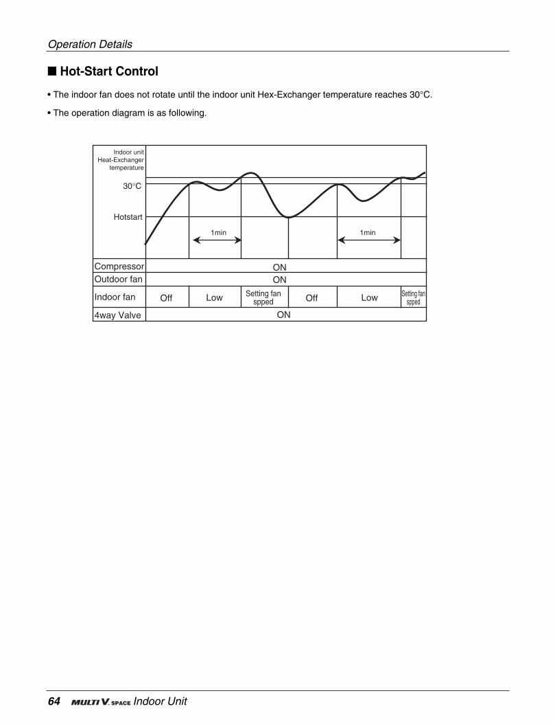
64 Indoor Unit
Hot-Start Control
• The indoor fan does not rotate until the indoor unit Hex-Exchanger temperature reaches 30°C.
• The operation diagram is as following.
Operation Details
ON ON
Off OffLow Low
1min1min
Hotstart
30°C
Indoor unitHeat-Exchanger
temperature
Setting fanspped
Setting fanspped
Compressor Outdoor fan
Indoor fan
4way Valve ON
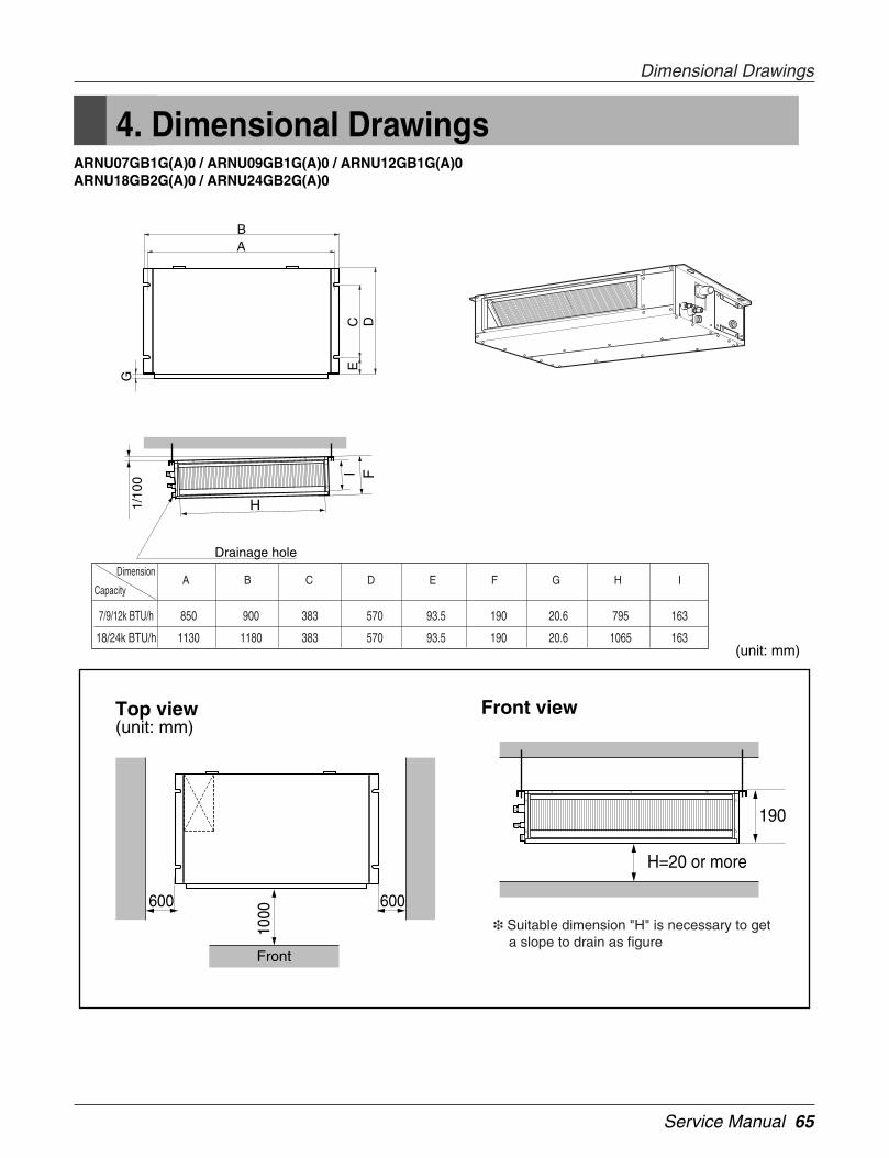
Service Manual 65
4. Dimensional DrawingsARNU07GB1G(A)0 / ARNU09GB1G(A)0 / ARNU12GB1G(A)0ARNU18GB2G(A)0 / ARNU24GB2G(A)0
Front viewTop view(unit: mm)
(unit: mm)
Suitable dimension "H" is necessary to get a slope to drain as figure
CE
G
D
AB
1/10
0
I F
H
Drainage hole
600600
190
Front
1000
H=20 or more
7/9/12k BTU/h 850 900 383 570 93.5 190 20.6 795 163
18/24k BTU/h 1130 1180 383 570 93.5 190 20.6 1065 163
Dimension
CapacityA B C D E F G H I
Dimensional Drawings
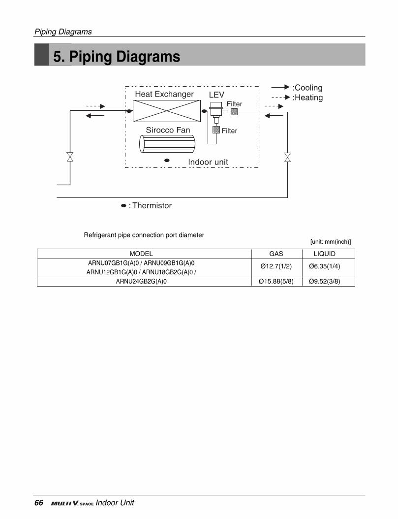
66 Indoor Unit
Piping Diagrams
5. Piping Diagrams
Heat Exchanger
Sirocco Fan
lndoor unit
LEV :Heating:Cooling
Filter
Filter
: Thermistor
Refrigerant pipe connection port diameter
MODEL GAS LIQUIDARNU07GB1G(A)0 / ARNU09GB1G(A)0 Ø12.7(1/2) Ø6.35(1/4)ARNU12GB1G(A)0 / ARNU18GB2G(A)0 /
ARNU24GB2G(A)0 Ø15.88(5/8) Ø9.52(3/8)
[unit: mm(inch)]

Service Manual 67
Wiring Diagrams
6. Wiring Diagrams
CONNECTORSPEC. COLOR DESCRIPTIONNUMBER
CN-MOTOR1 AC FAN MOTOR OUTPUT WHITE MOTOR OUTPUT OF PHASE CONTROL
CN-MOTOR2 AC FAN MOTOR OUTPUT WHITE MOTOR OUTPUT OF PHASE CONTROL
CN-PIPE/O DISCHARGE PIPE THERMISTOR RED DISCHARGE PIPE THERMISTOR
CN-PIPE PIPE SENSOR WHITE PIPE THERMISTOR
CN-ROOM ROOM SENSOR YELLOW ROOM THERMISTOR
CN-REMO REMOTE CONTROLLER WHITE REMOTE CONTROL LINE
CN-FLOAT FLOAT SWITCH INPUT BLUE FLOAT SWITCH SENSING
CN-LEV LEV OUTPUT WHITE LEV CONTROL OUTPUT
CN-D/PUMP DRAIN PUMP OUTPUT WHITE AC OUTPUT FOR DRAIN PUMP
CN-OPTION OPTION PWB. WHITE COMMUNICATION BETWEEN MAIN AND OPTION
CN-COM COMMUNICATION WHITE COMMUNICATION BETWEEN INDOOR AND OUTDOOR
CN-D/PUMP DRAIN PUMP OUTPUT WHITE AC OUTPUT FOR DRAIN PUMP
CN-POWER AC POWER SUPPLY WHITE AC POWER LINE INPUT FOR INDOOR CONTROLLER

68 Indoor Unit
1. Specifications .............................................................................69
2. Funtion ........................................................................................71
3. Operation Details........................................................................72
4. Dimensions .................................................................................75
5. Piping Diagrams .........................................................................76
6. Wiring Diagrams.........................................................................77
Ceiling Concealed Duct Type (High Static)
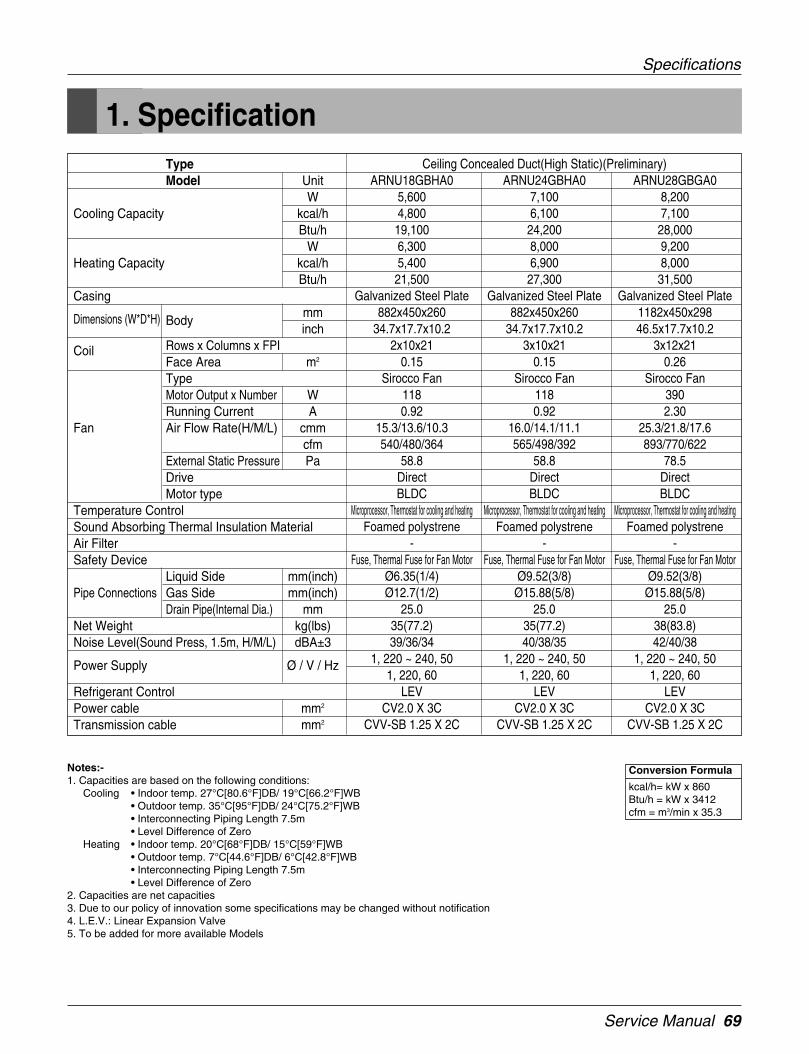
Service Manual 69
Conversion Formula
kcal/h= kW x 860Btu/h = kW x 3412cfm = m3/min x 35.3
Notes:-1. Capacities are based on the following conditions:
Cooling • Indoor temp. 27°C[80.6°F]DB/ 19°C[66.2°F]WB• Outdoor temp. 35°C[95°F]DB/ 24°C[75.2°F]WB• Interconnecting Piping Length 7.5m• Level Difference of Zero
Heating • Indoor temp. 20°C[68°F]DB/ 15°C[59°F]WB• Outdoor temp. 7°C[44.6°F]DB/ 6°C[42.8°F]WB• Interconnecting Piping Length 7.5m• Level Difference of Zero
2. Capacities are net capacities3. Due to our policy of innovation some specifications may be changed without notification4. L.E.V.: Linear Expansion Valve5. To be added for more available Models
TypeModel Unit
WCooling Capacity kcal/h
Btu/hW
Heating Capacity kcal/hBtu/h
Casing
Dimensions (W*D*H) Bodymminch
Coil Rows x Columns x FPIFace Area m2
TypeMotor Output x Number WRunning Current A
Fan Air Flow Rate(H/M/L) cmmcfm
External Static Pressure PaDriveMotor type
Temperature ControlSound Absorbing Thermal Insulation MaterialAir FilterSafety Device
Liquid Side mm(inch)Pipe Connections Gas Side mm(inch)
Drain Pipe(Internal Dia.) mmNet Weight kg(lbs)Noise Level(Sound Press, 1.5m, H/M/L) dBA±3
Power Supply Ø / V / Hz
Refrigerant ControlPower cable mm2
Transmission cable mm2
Ceiling Concealed Duct(High Static)(Preliminary)ARNU18GBHA0 ARNU24GBHA0 ARNU28GBGA0
5,600 7,100 8,2004,800 6,100 7,10019,100 24,200 28,0006,300 8,000 9,2005,400 6,900 8,00021,500 27,300 31,500
Galvanized Steel Plate Galvanized Steel Plate Galvanized Steel Plate882x450x260 882x450x260 1182x450x298
34.7x17.7x10.2 34.7x17.7x10.2 46.5x17.7x10.22x10x21 3x10x21 3x12x21
0.15 0.15 0.26Sirocco Fan Sirocco Fan Sirocco Fan
118 118 3900.92 0.92 2.30
15.3/13.6/10.3 16.0/14.1/11.1 25.3/21.8/17.6540/480/364 565/498/392 893/770/622
58.8 58.8 78.5Direct Direct DirectBLDC BLDC BLDC
Microprocessor, Thermostat for cooling and heating Microprocessor, Thermostat for cooling and heating Microprocessor, Thermostat for cooling and heatingFoamed polystrene Foamed polystrene Foamed polystrene
- - -Fuse, Thermal Fuse for Fan Motor Fuse, Thermal Fuse for Fan Motor Fuse, Thermal Fuse for Fan Motor
Ø6.35(1/4) Ø9.52(3/8) Ø9.52(3/8)Ø12.7(1/2) Ø15.88(5/8) Ø15.88(5/8)
25.0 25.0 25.035(77.2) 35(77.2) 38(83.8)39/36/34 40/38/35 42/40/38
1, 220 ~ 240, 50 1, 220 ~ 240, 50 1, 220 ~ 240, 501, 220, 60 1, 220, 60 1, 220, 60
LEV LEV LEVCV2.0 X 3C CV2.0 X 3C CV2.0 X 3C
CVV-SB 1.25 X 2C CVV-SB 1.25 X 2C CVV-SB 1.25 X 2C
1. Specification
Specifications

70 Indoor Unit
Conversion Formula
kcal/h= kW x 860Btu/h = kW x 3412cfm = m3/min x 35.3
Notes:-1. Capacities are based on the following conditions:
Cooling • Indoor temp. 27°C[80.6°F]DB/ 19°C[66.2°F]WB• Outdoor temp. 35°C[95°F]DB/ 24°C[75.2°F]WB• Interconnecting Piping Length 7.5m• Level Difference of Zero
Heating • Indoor temp. 20°C[68°F]DB/ 15°C[59°F]WB• Outdoor temp. 7°C[44.6°F]DB/ 6°C[42.8°F]WB• Interconnecting Piping Length 7.5m• Level Difference of Zero
2. Capacities are net capacities3. Due to our policy of innovation some specifications may be changed without notification4. L.E.V.: Linear Expansion Valve5. To be added for more available Models
TypeModel Unit
WCooling Capacity kcal/h
Btu/hW
Heating Capacity kcal/hBtu/h
Casing
Dimensions (W*D*H) Bodymminch
Coil Rows x Columns x FPIFace Area m2
TypeMotor Output x Number WRunning Current A
Fan Air Flow Rate(H/M/L) cmmcfm
External Static Pressure PaDriveMotor type
Temperature ControlSound Absorbing Thermal Insulation MaterialAir FilterSafety Device
Liquid Side mm(inch)Pipe Connections Gas Side mm(inch)
Drain Pipe(Internal Dia.) mmNet Weight kg(lbs)Noise Level(Sound Press, 1.5m, H/M/L) dBA±3
Power Supply Ø / V / Hz
Refrigerant ControlPower cable mm2
Transmission cable mm2
Ceiling Concealed Duct(High Static)(Preliminary)ARNU36GBGA0 ARNU42GBGA0 ARNU48GBRA0
10,600 12,300 14,1009,100 10,600 12,10036,200 42,000 48,10011,900 13,800 15,90010,200 11,000 13,20040,600 43,800 51,200
Galvanized Steel Plate Galvanized Steel Plate Galvanized Steel Plate1182x450x298 1182x450x298 1230x590x38046.5x17.7x10.2 46.5x17.7x10.2 48.4x23.2x15
3x12x21 3x12x21 3x13x190.26 0.26 0.38
Sirocco Fan Sirocco Fan Sirocco Fan390 390 3902.3 2.30 2.30
28.4/25.3/21.8 32.0/28.4/27.2 45/40/341003/893/770 1130/1003/960 1589/1413/1201
78.5 78.5 98.1Direct Direct DirectBLDC BLDC BLDC
Microprocessor, Thermostat for cooling and heating Microprocessor, Thermostat for cooling and heating Microprocessor, Thermostat for cooling and heatingFoamed polystrene Foamed polystrene Foamed polystrene
- - -Fuse, Thermal Fuse for Fan Motor Fuse, Thermal Fuse for Fan Motor Fuse, Thermal Fuse for Fan Motor
Ø9.52(3/8) Ø9.52(3/8) Ø9.52(3/8)Ø15.88(5/8) Ø15.88(5/8) Ø15.88(5/8)
25 25.0 25.038(83.8) 38(83.8) 53(117)44/42/40 46/44/42 48/46/44
1, 220 ~ 240, 50 1, 220 ~ 240, 50 1, 220 ~ 240, 501, 220, 60 1, 220, 60 1, 220, 60
LEV LEV LEVCV2.0 X 3C CV2.0 X 3C CV2.0 X 3C
CVV-SB 1.25 X 2C CVV-SB 1.25 X 2C CVV-SB 1.25 X 2C
Specifications
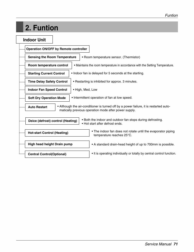
Service Manual 71
Funtion
2. FuntionIndoor Unit
Operation ON/OFF by Remote controller
Sensing the Room Temperature
Room temperature control
Starting Current Control
Time Delay Safety Control
Indoor Fan Speed Control
Soft Dry Operation Mode
Deice (defrost) control (Heating)
Auto Restart
Hot-start Control (Heating) • The indoor fan does not rotate until the evaporator pipingtemperature reaches 25°C.
High head height Drain pump • A standard drain-head height of up to 700mm is possible.
Central Control(Optional) • It is operating individually or totally by central control function.
• Room temperature sensor. (Thermistor)
• Maintains the room temperature in accordance with the Setting Temperature.
• Indoor fan is delayed for 5 seconds at the starting.
• Restarting is inhibited for approx. 3 minutes.
• High, Med, Low
• Intermittent operation of fan at low speed.
• Although the air-conditioner is turned off by a power failure, it is restarted auto-matically previous operation mode after power supply.
• Both the indoor and outdoor fan stops during defrosting.• Hot start after defrost ends.

72 Indoor Unit
Operation Details
Intake Air Temperature
SET TEMPERATURE +0.5°C(COMP. ON)
SET TEMPERATURE -0.5°C(COMP. OFF) More than More than
3 minutes 3 minutes
Selecting Selecting Selecting
fan speed fan speed fan speed
COMPRESSOR ON OFF ON OFF ON
INDOOR FAN Low Low
3. Operation Details
Time Delay safety Control• 30sec... The 4-way valve is ceased for 30sec. to prevent the refrigerant-gas abnormal noise when the Heating opera-
tion is OFF or switched to the other operation mode while compress is off.
While compressor is running, it takes 3~5 seconds to switch to another mode.
Soft-Dry Operation• The indoor fan speed is automatically set to the low, so the shift of the indoor fan speed is impossible because of
already being set to the best speed for Dry Operation by microcontroller control.
Cooling Mode Operation• When selecting the Cooling( ) Mode Operation, the unit will operate according to the setting by the remote controller
and the operation diagram is as following.
(1) The function of main control

Service Manual 73
Operation Details
Heating Mode OperationThe unit will operate according to the setting by the remote controller and the operation diagram is shown as following.
COMP
Outdoor fan
Indoor fan
4way valve
Setting Temperature(Compressor ON)
Setting Temperature +3°C
(Compressor OFF)
Indoor unitHeat-Exchangertemperature
30°C
27°C20°C
33°C
1minMinimum
3min 1min
3min
Settingfan
spped
Settingfan
spped
Settingfan
spped
40°C
ON
ON
ON
ON
LowLowLowLowLow OffOffOff
ON
OFF
OFF
Low fan during 10sec
A
A
B
B
Intake Air Temperature
• Compressor-off interval : - While the indoor Heat-Exchanger temperature is higher than 40°C, fan operates at low speed, when it becomes lower than 40°C fan stops. - For eluminating latent heat-loss, fan operates at low speed for 10 seconds periodically.
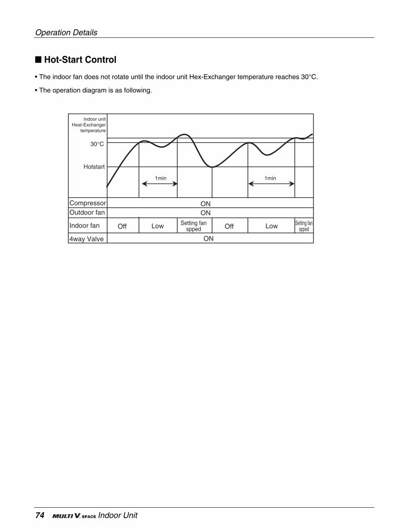
74 Indoor Unit
Hot-Start Control
• The indoor fan does not rotate until the indoor unit Hex-Exchanger temperature reaches 30°C.
• The operation diagram is as following.
ON ON
Off OffLow Low
1min1min
Hotstart
30°C
Indoor unitHeat-Exchanger
temperature
Setting fanspped
Setting fanspped
Compressor Outdoor fan
Indoor fan
4way Valve ON
Operation Details
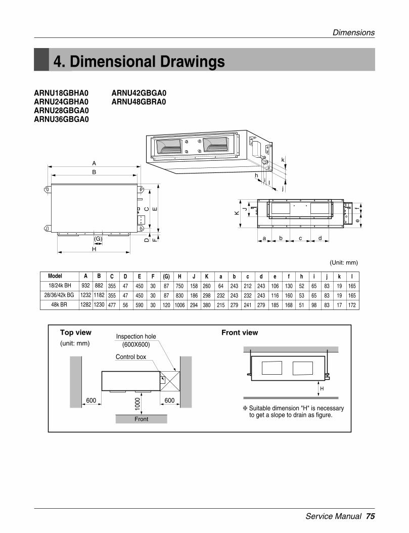
Service Manual 75
Dimensions
4. Dimensional Drawings
ARNU18GBHA0ARNU24GBHA0ARNU28GBGA0ARNU36GBGA0
ARNU42GBGA0ARNU48GBRA0
C D E F (G) H J K a b c d e f h i j k l
355 47 450 30 87 750 158 260 64 243 212 243 106 130 52 65 83 19 165
355 47 450 30 87 830 186 298 232 243 232 243 116 160 53 65 83 19 165
477 56 590 30 120 1006 294 380 215 279 241 279 185 168 51 98 83 17 172
Model A B
18/24k BH 932 882
28/36/42k BG 1232 1182
48k BR 1282 1230
(Unit: mm)
lih
j
kA
H
CD
EF
B
(G) a b c dK
J fe
Top view(unit: mm)
Front view
600600
Front
Inspection hole
Suitable dimension "H" is necessary to get a slope to drain as figure.
(600X600)
Control box
1000
H

76 Indoor Unit
5. Piping Diagrams
Heat Exchanger
Sirocco Fan
lndoor unit
LEV :Heating:Cooling
Filter
Filter
: Thermistor
Refrigerant pipe connection port diameter[unit: mm(inch)]
Piping Diagrams
MODEL GAS LIQUID
ARNU18GBHA0 Ø12.7(1/2) Ø6.35(1/4)
ARNU24GBHA0 Ø15.88(5/8) Ø9.52(3/8)
ARNU28GBGA0 Ø15.88(5/8) Ø9.52(3/8)
ARNU36GBGA0 Ø15.88(5/8) Ø9.52(3/8)
ARNU42GBGA0 Ø15.88(5/8) Ø9.52(3/8)
ARNU48GBRA0 Ø15.88(5/8) Ø9.52(3/8)
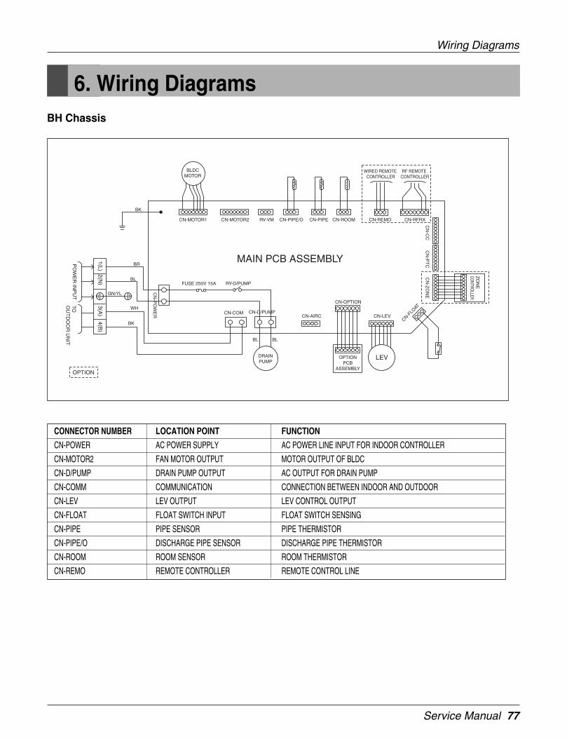
Service Manual 77
Wiring Diagrams
BH Chassis
CONNECTOR NUMBER LOCATION POINT FUNCTION
CN-POWER AC POWER SUPPLY AC POWER LINE INPUT FOR INDOOR CONTROLLER
CN-MOTOR2 FAN MOTOR OUTPUT MOTOR OUTPUT OF BLDC
CN-D/PUMP DRAIN PUMP OUTPUT AC OUTPUT FOR DRAIN PUMP
CN-COMM COMMUNICATION CONNECTION BETWEEN INDOOR AND OUTDOOR
CN-LEV LEV OUTPUT LEV CONTROL OUTPUT
CN-FLOAT FLOAT SWITCH INPUT FLOAT SWITCH SENSING
CN-PIPE PIPE SENSOR PIPE THERMISTOR
CN-PIPE/O DISCHARGE PIPE SENSOR DISCHARGE PIPE THERMISTOR
CN-ROOM ROOM SENSOR ROOM THERMISTOR
CN-REMO REMOTE CONTROLLER REMOTE CONTROL LINE
6. Wiring Diagrams
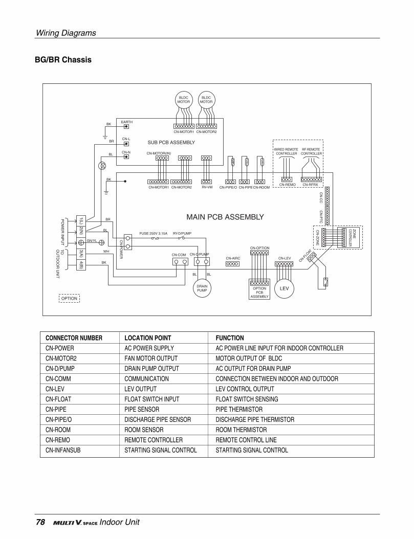
78 Indoor Unit
BG/BR Chassis
CONNECTOR NUMBER LOCATION POINT FUNCTION
CN-POWER AC POWER SUPPLY AC POWER LINE INPUT FOR INDOOR CONTROLLER
CN-MOTOR2 FAN MOTOR OUTPUT MOTOR OUTPUT OF BLDC
CN-D/PUMP DRAIN PUMP OUTPUT AC OUTPUT FOR DRAIN PUMP
CN-COMM COMMUNICATION CONNECTION BETWEEN INDOOR AND OUTDOOR
CN-LEV LEV OUTPUT LEV CONTROL OUTPUT
CN-FLOAT FLOAT SWITCH INPUT FLOAT SWITCH SENSING
CN-PIPE PIPE SENSOR PIPE THERMISTOR
CN-PIPE/O DISCHARGE PIPE SENSOR DISCHARGE PIPE THERMISTOR
CN-ROOM ROOM SENSOR ROOM THERMISTOR
CN-REMO REMOTE CONTROLLER REMOTE CONTROL LINE
CN-INFANSUB STARTING SIGNAL CONTROL STARTING SIGNAL CONTROL
Wiring Diagrams
Service Manual 79
Outdoor unit
80 Outdoor Unit
1. Specifications .............................................................................81
2. Parts.............................................................................................82
3. Dimensions .................................................................................85
4. Piping Diagrams .........................................................................86
5. Wiring Diagrams .........................................................................87
6. Function ......................................................................................90
7. Test Run ....................................................................................104
ARUN Series

Service Manual 81
1. Specification
Specification
Notes:1. Capacities are based on the following conditions:
Cooling * Indoor temp. 27°C[80.6°F]DB/ 19°C[66.2°F]WB* Outdoor temp. 35°C[95°F]DB/ 24°C[75.2°F]WB* Interconnecting Piping Length 7.5m* Level Difference of Zero
Heating * Indoor temp. 20°C[68°F]DB/ 15°C[59°F]WB* Outdoor temp. 7°C[44.6°F]DB/ 6°C[42.8°F]WB* Interconnecting Piping Length 7.5m* Level Difference of Zero
2. Capacities are net capacities3. Due to our policy of innovation some specifications may be changed without notification4. L.E.V.:Linear Expansion Valve
Conversion Formula
Kcal/h= kW x 860Btu/h = kW x 3412cfm = m3/min x 35.3
Heat Pump(50Hz)
HPModel Name
Capacity Cooling Wkcal/hBtu/h
Heating Wkcal/hBtu/h
Input Cooling kWHeating kW
Casing ColorHeat ExchangerCompressor Type
MakerPiston Displacement cm2/revNumber of Revolution r.p.mMotor Output x Number WStarting MethodOil TypeOil Charge CC
Fan TypeMotor Output x Number WAir Flow Rate(High) cmm
cfmDriveDischarge
Pipe Connctions Liquid Pipes mm(inch)Gas Pipes mm(inch)
Dimensions (W*H*D) mminch
Net Weight kglbs
Transmission Cable mm2
Refigerant Refigerant nameControl
Power Supply Ø / V / Hz
10ARUN1008F20
28,00024,10095,50031,50027,100107,500
7.187.69
WARM GRAYLouver Fin
RotaryMatsushita
42.4*23450*24500*2
Direct on LineFV50S(PVE)
1300*2Siroco Fan
840*2170
6,004InverterFront
Ø9.52(3/8)Ø22.2(7/8)
1400*1790*65055.1*70.5*25.6
350771.6
CVV-SB 1.25X2CR410AL.E.V
3 / 380 ~ 415 / 50

82 Outdoor Unit
Parts
Parts Name
Compressor
Inverter fan motor
Outdoor LEV
Subcooler LEV
Oil Pass Valve
Oil Equalization Valve
Hot gas bypass
valve
4 Way valve
Outdoor check valve
High pressure S/W
High pressure sensor
Low pressure sensor
Heat exchanger temperature sensor
Compressor discharge temperature sensor
Air temperature sensor
Suction temperature sensor
Liquid tube temperature sensor
Subcooler outlet temperature sensor
Subcooler inlet temperature sensor
Discharge check valve
Symbol
COMP.
IMT
OLEV
SLEV
OPV
OEV
HGV
4 WAY
OCHK
HPSW
HPS
LPS
THEX
TCOMP
TAIR
TSUC
TLIQ
TSOUT
TSIN
DCHK
Major Function
Operated up to 20Hz~100Hz by inverter operation. Pressurize hightemperature, low pressure refrigerant to high temperature, high
pressure.
Adjust outdoor wind quantity while varying the outdoor fan by 0~65Hz.
Adjust flow quantity depending on overheat level of refrigerant in theoutdoor side in heat status.
Adjust flow quantity depending on overheat level of the outlet of theexcessive cold heat exchanger in cold status.
Stabilize the system by high pressure gas to the low pressure partafter opening when bypass and low pressure of refrigerant rapidly
reduces to less than the valve valve.
Cut-off the outdoor heat exchanger with the evaporator or condenserdepending on operation of the indoor unit.
Used to obtain flow quantity of refrigerant in cold condition.
Mechanically stop the compressor where the compressor rises to thehigh pressure limit valve due to abnormal operation.
Measure high pressure of the system.
Measure low pressure of the system..
Used for control by measuring temperature of the outdoor heatexchanger.
Used for protecting and controlling the compressor by measuringdischarger temperature.
Measure outdoor temperature.
Used for controlling super heat level by measuring refrigeranttemperature of the suction pipe.
Used for controlling sub cool level by measuring refrigeranttemperature of the liquid pipe.
Used for controlling super heat level by measuring outlettemperature of the subcooler circuit.
Used for controlling super heat level by measuring outlettemperature of the subcooler circuit.
Prevent reverse flow of high pressure refrigerant into the compressor.
2. Parts2.1 10HP Parts Function
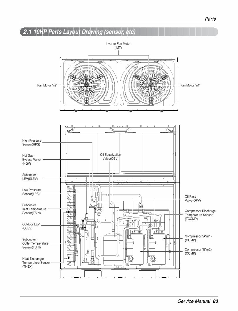
Service Manual 83
Inverter Fan Motor(IMT)
Fan Motor "n2" Fan Motor "n1"
High PressureSensor(HPS)
Oil EqualizationValve(OEV)
Hot GasBypass Valve(HGV)
SubcoolerLEV(SLEV)
Low PressureSensor(LPS)
Oil PassValve(OPV)
Compressor DischargeTemperature Sensor(TCOMP)
Compressor "A"(n1)(COMP)
Compressor "B"(n2)(COMP)
Outdoor LEV(OLEV)
SubcoolerInlet TemperatureSensor(TSIN)
SubcoolerOutlet TemperatureSensor(TSIN)
Heat ExchangerTemperature Sensor(THEX)
2.1 10HP Parts Layout Drawing (sensor, etc)
Parts
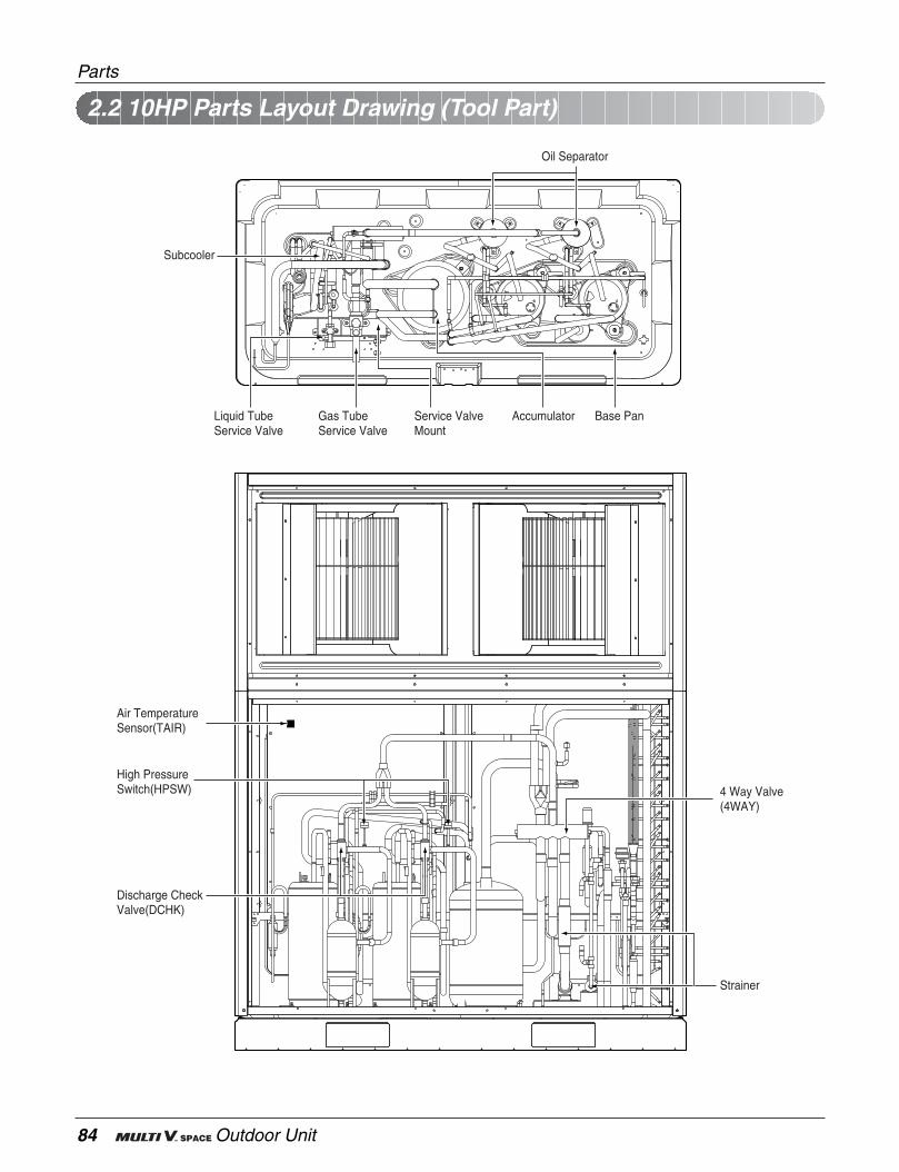
84 Outdoor Unit
Subcooler
Liquid TubeService Valve
Gas TubeService Valve
Service ValveMount
Accumulator
Oil Separator
Base Pan
Air TemperatureSensor(TAIR)
4 Way Valve(4WAY)
Strainer
High PressureSwitch(HPSW)
Discharge Check Valve(DCHK)
2.2 10HP Parts Layout Drawing (Tool Part)
Parts

Service Manual 85
2.3 10HP Parts Layout Drawing (Control Part)
Parts
Main PCB
Fan PCB (n1)
Inverter PCB (n1)Inverter PCB (n2)
Fan PCB (n2)

86 Outdoor Unit
3. Dimensions
Dimensions
650
1790
110
75
1114
4065
136
595
954
676
203
68 197640
7065 516
650
1400
14001320
1373(Anchor Bolt)
1400
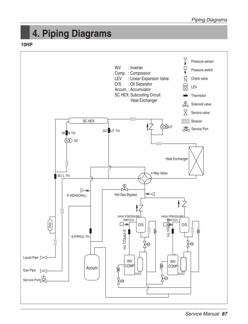
Service Manual 87
4. Piping Diagrams
Piping Diagrams
10HP
S
Pressure sensor
Pressure switch
Check valve
LEV
Thermistor
Solenoid valve
Service valve
Strainer
INV : InverterComp. : CompressorLEV : Linear Expansion ValveO/S : Oil SeparatorAccum. : AccumulatorSC HEX: Subcooling Circuit Heat Exchanger
Hot Gas Bypass
Accum
4 Way Valve
Heat Exchanger
SC-OUT TH.OUT
HIGH PRESSURESWITCH
D-P
IPE
(I) TH.
CO
MP
.IN
V
SC-IN TH.
HIGH PRESSURESWITCH
CO
MP
.IN
V
SC-L TH.
P-SENSOR(L)
S-PIPE(I) TH.
Liquid Pipe
Gas Pipe
Service Port
D-P
IPE
(C) TH
.
Service Port
O/S O/S
S
S
INVCOMP
INVCOMP
S
S
S
SC HEX
SC
Drie
r

88 Outdoor Unit
5. Wiring Diagrams
Wiring Diagrams

Service Manual 89
Inverter Board
Main Board
CONNECTOR No. SPEC DESCRIPTIONCN1 POWER AC POWERCN2 DC-LINK DC LINK VOLTAGE DETECTCN4 H/P, M HIGH PRESSURE MAGNETIC SWITCHCN5 PHASE 3 PHASE DETECTCN6 COMMUNICATION COMMUNICATION SIGNAL WITH MAIN PCBCN7 FAN HEATSINK FAN HEATSINK TEMPERATURE SENSORCN8 INV. HEATSINK INV. HEATSINK TEMPERATURE SWNSORCN9 COMMUNICATION COMMUNICATION SIGNAL WITH FAN PCB
CN114-1,2 COMP. IPM POWER CABLE FROM IPM TO COMP.CN15 INPUT CURRENT INPUT CURRENT SENSINGCN18 ON-BOARD ON-BOARD WRITING PORT
CN_COOLFAN COOLFAN COOLING FAN OF HEATSINKCN_IPM IPM CONTROL SIGNAL FOR PWM
CN_GATE, CN_GATE1 IPM PWM CONTROL POWERCN_MOTOR1 FAN MOTOR FAN OF OUTDOOR UNIT
CONNECTOR No. SPEC DESCRIPTIONCN01 AC POWER IN AC POWERCN02 AC TRANS IN AC POWER TO TRANSCN03 AC TRANS OUT AC POWER FROM TRANSCN04 4WAY 4WAY REVERSING VALVECN05 LIQ(I) NVERTER COMP LIQUID INJECTION VALVECN06 LIQ(C) CONSTANT COMP LIQUID INJECTION VALVECN07 HEATER(I) INVERTER COMP CRANK HEATERCN08 HEATER(C) CONSTANT COMP CRANK HEATERCN10 HOT-GAS HOT GAS BYPASS VALVECN11 OILPASS(I) NOT USECN12 OILPASS(C) NOT USECN14 MAGNET(C) MAGNETIC SWITCHCN15 COOLING FAN HEATSINK FANCN16 LEV-OUT LINEAR EXPANSION VALVE(MAIN)CN17 LEV-SC LINEAR EXPANSION VALVE(SUBCOOLING CIRCUIT)CN18 TO-JIG TRANSMISSION WITH JIGCN19 CEN-CONTROL/WRITE TRANSMISSION WITH CENTRAL CONTROLLERCN20 TO FAN BOARD TRANSMISSION WITH FAN BOARDCN21 TO INVERTER BOARD TRANSMISSION WITH INVERTER BOARDCN22 TO INDOOR UNIT TRANSMISSION WITH INDOOR UNITCN23 TO SUB OUTDOOR TRANSMISSION WITH SUB OUTDOOR UNIT
OUT-AIR OUTDOOR AIR THERMISTORCN25 S_PIPE(I) INVERTER COMP SUCTION PIPE THERMISTOR
D_PIPE(C) CONSTANT COMP DISCHARGE PIPE THERMISTORD_PIPE(I) INVERTER COMP DISCHARGE PIPE THERMISTOR
CN26 HEX_PIPE(C) CONDENSOR PIPE THERMISTOR(C)HEX_PIPE(I) CONDENSOR PIPE THERMISTOR(I)
SC-OUT SUBCOOLING CIRCUIT OUTLET PIPE THERMISTORCN27 SC-IN SUBCOOLING CIRCUIT INLET PIPE THERMISTOR
SC-L SUBCOOLING CIRCUIT LIQUID PIPE THERMISTORCN28 P-SEN(H) HIGH PRESSURE SENSORCN29 P-SEN(L) LOW PRESSURE SENSORJIG 1 JIG JIG POWERJIG 2 JIG JIG POWERCN36 LEV-HOUT LINEAR EXPANSION VALVE(MAIN)CN24 DRY CONTACT OPERATING MODE LOCKING(COOL, HOT ,GENERAL)CN34 DRY CONTACT OPERATING MODE LOCKING(COOL, HOT ,GENERAL)
Wiring Diagrams
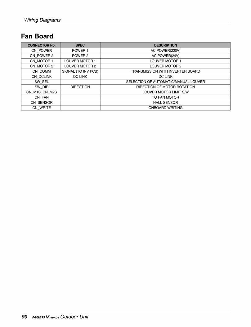
90 Outdoor Unit
Wiring Diagrams
Fan BoardCONNECTOR No. SPEC DESCRIPTION
CN_POWER POWER 1 AC POWER(220V)CN_POWER 2 POWER 2 AC POWER(24V)CN_MOTOR 1 LOUVER MOTOR 1 LOUVER MOTOR 1CN_MOTOR 2 LOUVER MOTOR 2 LOUVER MOTOR 2
CN_COMM SIGNAL (TO INV PCB) TRANSMISSION WITH INVERTER BOARDCN_DCLINK DC LINK DC LINK
SW_SEL SELECTION OF AUTOMATIC/MANUAL LOUVERSW_DIR DIRECTION DIRECTION OF MOTOR ROTATION
CN_M1S, CN_M2S LOUVER MOTOR LIMIT S/WCN_FAN TO FAN MOTOR
CN_SENSOR HALL SENSORCN_WRITE ONBOARD WRITING
Service Manual 91
6. Function
1. Basic control ...................................................................................................................921.1 Normal operation .......................................................................................................921.2 Compressor control....................................................................................................921.3 Main and sub unit's LEV control.................................................................................921.4 Fan control .................................................................................................................92
2. Special control ................................................................................................................932.1 Oil return control ........................................................................................................932.2 Defrost control............................................................................................................952.3 Oil equalizing control..................................................................................................962.4 Stopping operation.....................................................................................................96
3. Protection control ...........................................................................................................973.1 Pressure protection control ........................................................................................973.2 Discharge temperature control...................................................................................993.3 Inverter protection control ..........................................................................................993.4 Liquid back control ...................................................................................................1003.5 Phase detection .......................................................................................................100
4. Other control .................................................................................................................1014.1 Initial setup...............................................................................................................1014.2 Instant indoor unit checking mode ...........................................................................1034.3 Emergency operation...............................................................................................104

92 Outdoor Unit
1.1 Normal operation
Note: Heating operation is not functional at an outdoor air temperature of 27°C or more
1.2 Compressor controlFuzzy control : Maintain evaporating temperature(Te) to be constant on cooling mode and condensing tem-perature(Tc) on heating mode by Fuzzy control to ensure the stable system performance.(Tc:47 ~51°C, Te:2 ~ 5°C)
(1) Cooling modeTe can be set by initial dip switch setting. (Normal mode, capacity up mode, and energy save mode)
(2) Heating modeTc can be set by initial dip switch setting. (Normal mode, capacity up mode, and energy save mode)
1.3 Main LEV controlMain LEV operates with fuzzy control rules to keep the degree of super Heat(Superheat) (about 3°C)at theevaporator outlet stable during heating modeThe degree of Superheat = Tsuction - TevaporationTsuction : temperature at suction pipe sensor(°C)Tevaporation : evaporation temperature equivalent to low pressure(°C)
1.4 Fan controlThe fan motors of the main unit are operated by the inverter drive with fuzzy control rules.
1. Basic control
Compressor
Fan
Main LEV
4way valve
SubcoolingLEV
Fuzzy control
Fuzzy control
Full open
Off
Fuzzy control
Fuzzy control
Fuzzy control
Fuzzy control
On
min.
Cooling operation Heating operationActuator
stop
stop
After 15min, min. pulse
After 15min, Off
After 15min, min. pulse
Stop state
Function
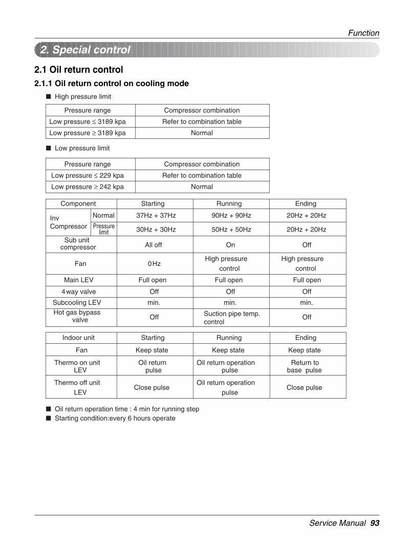
Service Manual 93
2.1 Oil return control2.1.1 Oil return control on cooling mode
High pressure limit
Low pressure limit
Oil return operation time : 4 min for running step Starting condition:every 6 hours operate
InvCompressor
Normal
Pressurelimit
Fan
Main LEV
4way valve
Subcooling LEV
37Hz + 37Hz 90Hz + 90Hz 20Hz + 20Hz
30Hz + 30Hz 50Hz + 50Hz 20Hz + 20Hz
0Hz
Full open
Off
min.
StartingComponent
Pressure range
Low pressure ≤ 229 kpa
Low pressure ≥ 242 kpa
Compressor combination
Refer to combination table
Normal
Sub unitcompressor All off
Hot gas bypassvalve Off
High pressure control
Full open
Off
min.
Running
On
Suction pipe temp. control
High pressure control
Full open
Off
min.
Ending
Off
Off
Fan Keep state
StartingIndoor unit
Thermo on unitLEV
Oil returnpulse
Keep state
Running
Oil return operationpulse
Keep state
Ending
Return tobase pulse
Thermo off unitLEV
Close pulseOil return operation
pulseClose pulse
Pressure range
Low pressure ≤ 3189 kpa
Low pressure ≥ 3189 kpa
Compressor combination
Refer to combination table
Normal
2. Special control
Function
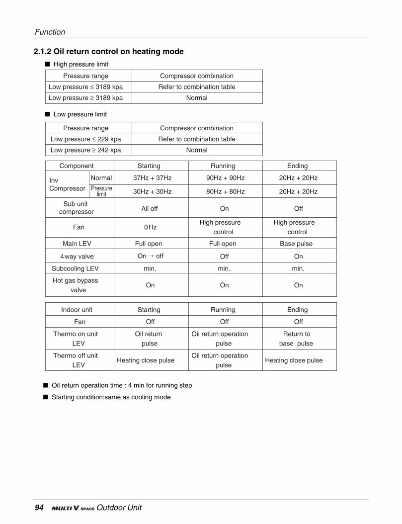
94 Outdoor Unit
2.1.2 Oil return control on heating mode
High pressure limit
Low pressure limit
Oil return operation time : 4 min for running step
Starting condition:same as cooling mode
Fan
Main LEV
4way valve
Subcooling LEV
0Hz
Full open
On off
min.
StartingComponent
Sub unitcompressor All off
Hot gas bypassvalve
On
High pressure control
Full open
Off
min.
Running
On
On
High pressure control
Base pulse
On
min.
Ending
Off
On
Fan Off
StartingIndoor unit
Thermo on unitLEV
Oil returnpulse
Off
Running
Oil return operationpulse
Off
Ending
Return tobase pulse
Thermo off unitLEV
Heating close pulseOil return operation
pulseHeating close pulse
InvCompressor
Normal
Pressurelimit
37Hz + 37Hz 90Hz + 90Hz 20Hz + 20Hz
30Hz + 30Hz 80Hz + 80Hz 20Hz + 20Hz
Pressure range
Low pressure ≤ 229 kpa
Low pressure ≥ 242 kpa
Compressor combination
Refer to combination table
Normal
Pressure range
Low pressure ≤ 3189 kpa
Low pressure ≥ 3189 kpa
Compressor combination
Refer to combination table
Normal
Function
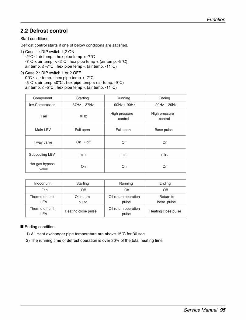
Service Manual 95
Inv Compressor
Fan
Main LEV
4way valve
Subcooling LEV
37Hz + 37Hz 90Hz + 90Hz 20Hz + 20Hz
0Hz
Full open
On off
min.
StartingComponent
Hot gas bypassvalve
On
High pressure control
Full open
Off
min.
Running
On
High pressure control
Base pulse
On
min.
Ending
On
Fan Off
StartingIndoor unit
Thermo on unitLEV
Oil returnpulse
Off
Running
Oil return operationpulse
Off
Ending
Return tobase pulse
Thermo off unitLEV
Heating close pulseOil return operation
pulseHeating close pulse
Function
2.2 Defrost controlStart conditions
Defrost control starts if one of below conditions are satisfied.
1) Case 1 : DIP switch 1,2 ON-2°C ≤ air temp. : hex pipe temp < -7°C-7°C < air temp. < -2°C : hex pipe temp < (air temp. -9°C)air temp. ≤ -7°C : hex pipe temp < (air temp. -11°C)
2) Case 2 : DIP switch 1 or 2 OFF0°C ≤ air temp. : hex pipe temp < -7°C-5°C < air temp.<0°C : hex pipe temp < (air temp. -9°C)air temp. ≤ -5°C : hex pipe temp < (air temp. -11°C)
Ending condition
1) All Heat exchanger pipe temperature are above 15˚C for 30 sec.
2) The running time of defrost operation is over 30% of the total heating time
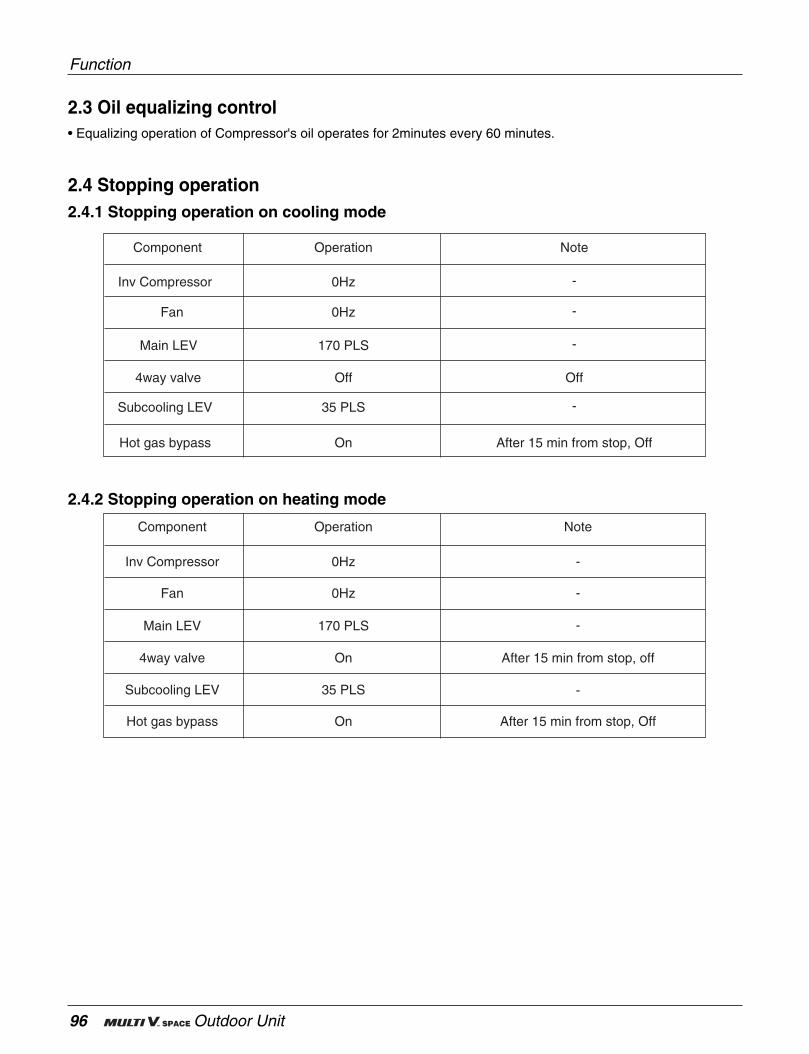
96 Outdoor Unit
Function
2.3 Oil equalizing control• Equalizing operation of Compressor's oil operates for 2minutes every 60 minutes.
2.4 Stopping operation2.4.1 Stopping operation on cooling mode
2.4.2 Stopping operation on heating mode
Inv Compressor
Fan
Main LEV
4way valve
Subcooling LEV
0Hz
0Hz
170 PLS
On
35 PLS
OperationComponent
After 15 min from stop, off
Note
Hot gas bypass On After 15 min from stop, Off
Inv Compressor
Fan
Main LEV
4way valve
Subcooling LEV
0Hz
0Hz
170 PLS
Off
35 PLS
OperationComponent
Off
-
-
-
-
-
-
-
-
Note
Hot gas bypass On After 15 min from stop, Off
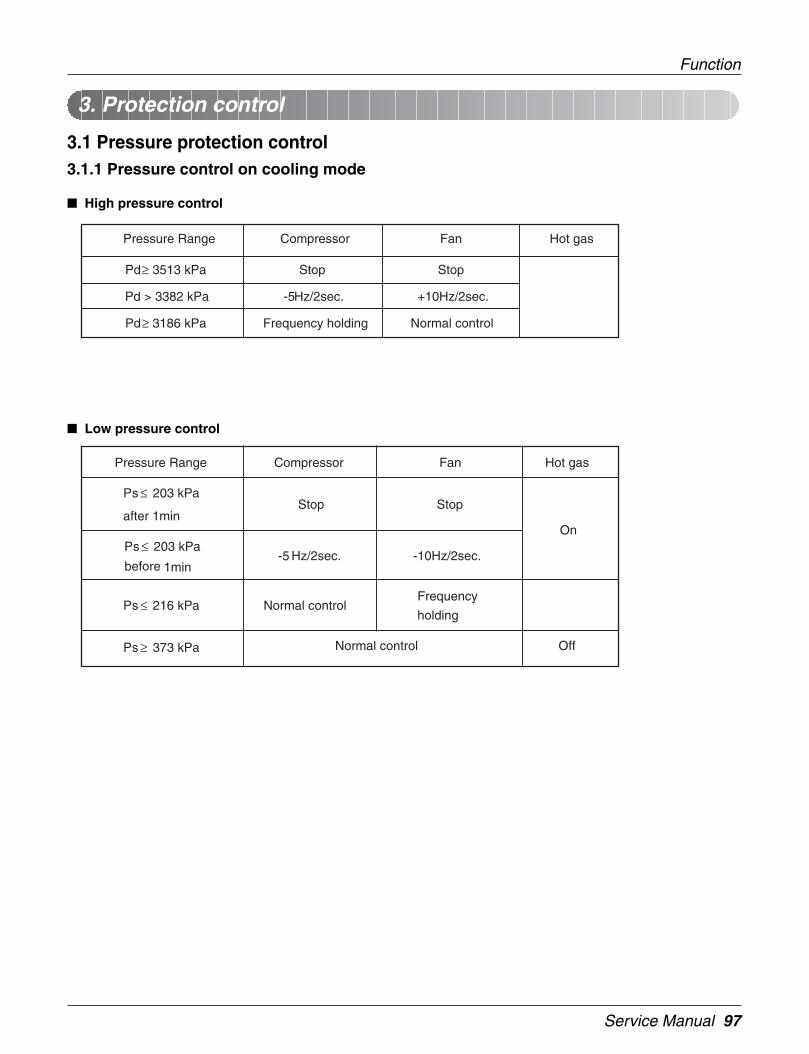
Service Manual 97
Function
3.1 Pressure protection control3.1.1 Pressure control on cooling mode
High pressure control
Low pressure control
3. Protection control
StopStopPd ≥ 3513 kPa
Normal controlFrequency holdingPd ≥ 3186 kPa
+10Hz/2sec.-5Hz/2sec.Pd > 3382 kPa
Hot gasFanCompressorPressure Range
Frequency
holdingNormal controlPs ≤ 216 kPa
OffNormal controlPs ≥ 373 kPa
On
-10Hz/2sec.-5 Hz/2sec.Ps ≤ 203 kPa
before 1min
StopStopPs ≤ 203 kPa
after 1min
Hot gasFanCompressorPressure Range

98 Outdoor Unit
3.1.2 Pressure control on heating mode
High pressure control
Low pressure control
Frequency holding
Normal control
OnStopStopPd ≥ 3513Pa
On-5Hz/2sec.-5Hz/2sec.Pd ≥ 3317 kPa
Pd ≤ 3186 kPa
off
Normal control
Pd≤ Target press -5
Hot gasFanCompressorPressure Range
Normal controlFrequency
holdingPs ≤ 216 kPa
Normal controlPs ≤ 242 kPa
OffPs ≥ 281 kPa
+10Hz/2sec.-5 Hz/2sec.Ps ≤ 203 kPa before 1min On
StopStopPs ≤ 203 kPa
after 1min
Hot gasFanCompressorPressure Range
Function
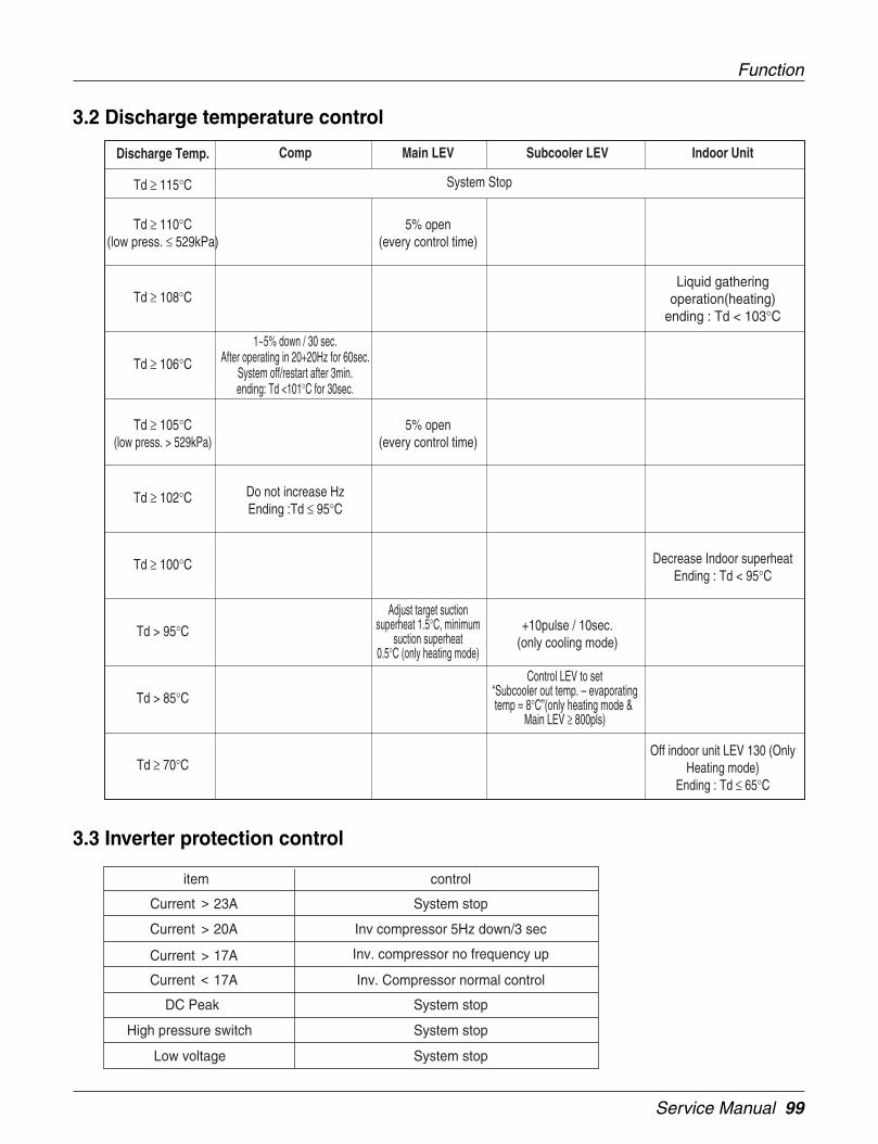
Service Manual 99
Function
3.2 Discharge temperature control
3.3 Inverter protection control
System stopCurrent 23A
item control
Inv compressor 5Hz down/3 secCurrent 20A
Inv. compressor no frequency upCurrent 17A
Inv. Compressor normal controlCurrent 17A
System stopDC Peak
System stopHigh pressure switch
System stopLow voltage
<
<
<
<
Off indoor unit LEV 130 (OnlyHeating mode)
Ending : Td ≤ 65°CTd ≥ 70°C
Do not increase HzEnding :Td ≤ 95°C
Td ≥ 102°C
1~5% down / 30 sec.After operating in 20+20Hz for 60sec.
System off/restart after 3min.ending: Td <101°C for 30sec.
Td ≥ 106°C
5% open(every control time)
Td ≥ 110°C(low press. ≤ 529kPa)
Liquid gatheringoperation(heating)
ending : Td < 103°CTd ≥ 108°C
Control LEV to set“Subcooler out temp. – evaporatingtemp = 8°C”(only heating mode &
Main LEV ≥ 800pls)
+10pulse / 10sec.(only cooling mode)
Subcooler LEV
Td > 85°C
Adjust target suctionsuperheat 1.5°C, minimum
suction superheat0.5°C (only heating mode)
Td > 95°C
5% open(every control time)
Td ≥ 105°C(low press. > 529kPa)
Decrease Indoor superheatEnding : Td < 95°C
Td ≥ 100°C
Main LEV Indoor Unit
System StopTd ≥ 115°C
CompDischarge Temp.
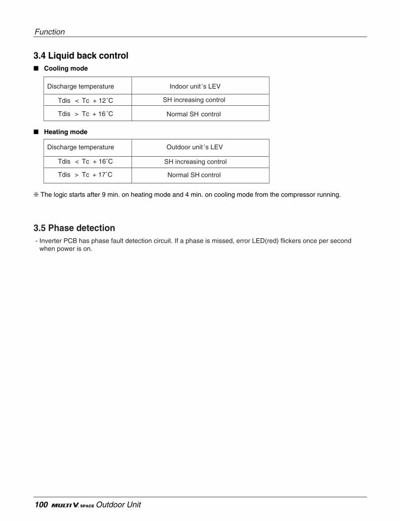
100 Outdoor Unit
3.4 Liquid back control Cooling mode
Heating mode
The logic starts after 9 min. on heating mode and 4 min. on cooling mode from the compressor running.
Tdis < Tc + 12˚C
Discharge temperature Indoor unit ’s LEV
Normal SH controlTdis > Tc + 16 ˚C
SH increasing control
SH increasing control
Tdis < Tc + 16˚C
Discharge temperature Outdoor unit ’s LEV
Normal SH controlTdis > Tc + 17˚C
Function
3.5 Phase detection- Inverter PCB has phase fault detection circuit. If a phase is missed, error LED(red) flickers once per second
when power is on.
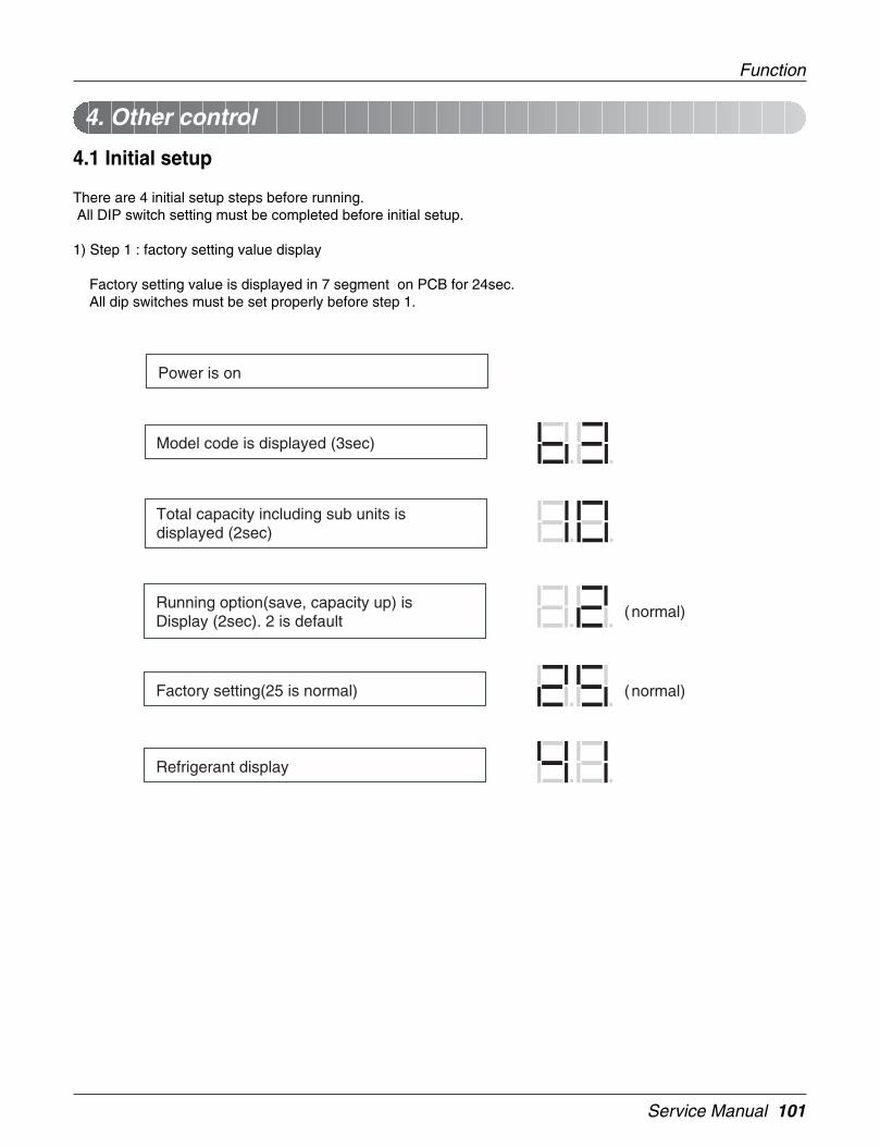
Service Manual 101
4.1 Initial setup
There are 4 initial setup steps before running.All DIP switch setting must be completed before initial setup.
1) Step 1 : factory setting value display
Factory setting value is displayed in 7 segment on PCB for 24sec.All dip switches must be set properly before step 1.
4. Other control
Power is on
Model code is displayed (3sec)
Total capacity including sub units is displayed (2sec)
Running option(save, capacity up) is Display (2sec). 2 is default
(normal)
Factory setting(25 is normal) (normal)
Refrigerant display
Function
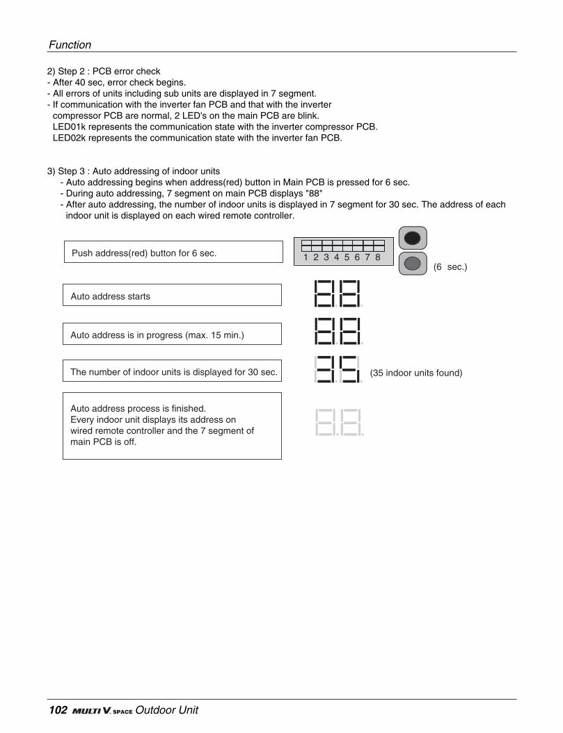
102 Outdoor Unit
2) Step 2 : PCB error check- After 40 sec, error check begins.- All errors of units including sub units are displayed in 7 segment.- If communication with the inverter fan PCB and that with the inverter
compressor PCB are normal, 2 LED's on the main PCB are blink.LED01k represents the communication state with the inverter compressor PCB.LED02k represents the communication state with the inverter fan PCB.
3) Step 3 : Auto addressing of indoor units- Auto addressing begins when address(red) button in Main PCB is pressed for 6 sec.- During auto addressing, 7 segment on main PCB displays "88"- After auto addressing, the number of indoor units is displayed in 7 segment for 30 sec. The address of each
indoor unit is displayed on each wired remote controller.
Push address(red) button for 6 sec.
Auto address starts
Auto address is in progress (max. 15 min.)
The number of indoor units is displayed for 30 sec. (35 indoor units found)
Auto address process is finished.Every indoor unit displays its address on wired remote controller and the 7 segment of main PCB is off.
1 2 3 4 5 6 7 8(6 sec.)
Function
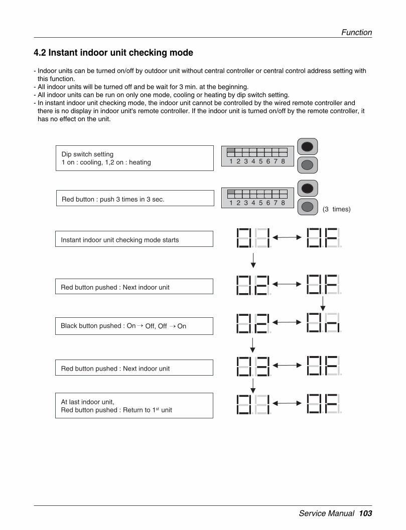
Service Manual 103
Function
4.2 Instant indoor unit checking mode
- Indoor units can be turned on/off by outdoor unit without central controller or central control address setting withthis function.
- All indoor units will be turned off and be wait for 3 min. at the beginning.- All indoor units can be run on only one mode, cooling or heating by dip switch setting.- In instant indoor unit checking mode, the indoor unit cannot be controlled by the wired remote controller and
there is no display in indoor unit's remote controller. If the indoor unit is turned on/off by the remote controller, ithas no effect on the unit.
Red button : push 3 times in 3 sec.
Instant indoor unit checking mode starts
Red button pushed : Next indoor unit
Black button pushed : On Off, Off On
(3 times)
Red button pushed : Next indoor unit
At last indoor unit, Red button pushed : Return to 1st unit
Dip switch setting1 on : cooling, 1,2 on : heating 1 2 3 4 5 6 7 8
1 2 3 4 5 6 7 8

104 Outdoor Unit
4.3 Emergency operation
- If a compressor is out of order, the system can be run except the defective compressor by backup function.To set backup function, set DIP switch like following pictures.
1 2 3 4 5 6 7 8
Normal
A Comp. Failure
B Comp. Failure
1 2 3 4 5 6 7 8
A Comp. B Comp.
A Comp.Failed
B Comp.
A Comp. B Comp.Failed
Function

Service Manual 105
Test Run
7. Test Run
1
2
3
4
Check to see whether there is any refrigerant leakage, and slack of power or transmission cable.
Confirm that 500 V megger shows 2.0 MΩ or more between power supply terminal block and ground.Do not operate in the case of 2.0 MΩ or less.
NOTE: Never carry out megaohm check over terminal control board. Otherwise the control boardwould be broken.Immediately after mounting the unit or after leaving it turned off for an extended length of time,the resistance of the insulation between the power supply terminal board and the ground maydecrease to approx. 2 MΩ as a result of refrigerant accumulating in the internal compressor.If the insulation resistance is less than 2 MΩ, turning on the main power supply and energizingthe crankcase heater for more than 6 hours will cause the refrigerant to evaporate, increasingthe insulation resistance.
Check if high/low pressure common pipe, liquid pipe and gas pipe valves are fully opened.
NOTE: Be sure to tighten caps.
Check if there are any problems in automatic addressing or not:Check and confirm that there are no error messages in the display of indoor units or remote controlsand LED in outdoor units.
7.1 Checks Before Test Run
CAUTION
when cutting main power of the Multi V• Always apply main power of the outdoor unit during use of product
(cooling season/heating season).
• Always apply power before 6 hours to heat the crank case heater where performing test run afterinstallation of product. It may result in burning out of the compressor if not preheating the crankcase with the electrical heater for more than 6 hours.(In case of the outdoor temperature below 10°C)
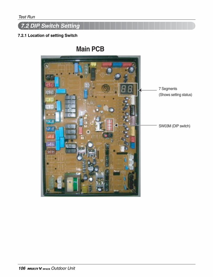
106 Outdoor Unit
7.2.1 Location of setting Switch
Main PCB
7 Segments
(Shows setting status)
SW03M (DIP switch)
7.2 DIP Switch Setting
Test Run
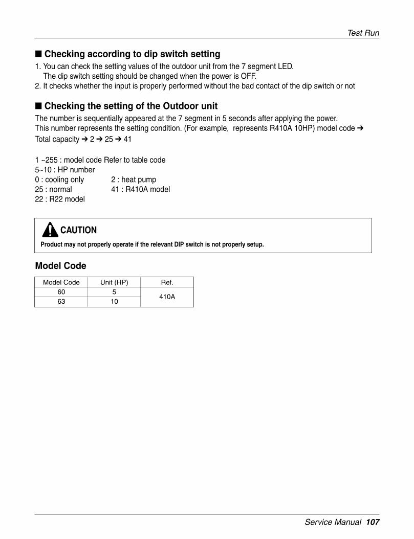
Service Manual 107
Test Run
Checking according to dip switch setting1. You can check the setting values of the outdoor unit from the 7 segment LED.
The dip switch setting should be changed when the power is OFF.2. It checks whether the input is properly performed without the bad contact of the dip switch or not
Checking the setting of the Outdoor unitThe number is sequentially appeared at the 7 segment in 5 seconds after applying the power.This number represents the setting condition. (For example, represents R410A 10HP) model code
Total capacity 2 25 41
1 ~255 : model code Refer to table code5~10 : HP number0 : cooling only 2 : heat pump25 : normal 41 : R410A model22 : R22 model
CAUTIONProduct may not properly operate if the relevant DIP switch is not properly setup.
Model Code
Model Code Unit (HP) Ref.60 5
410A63 10
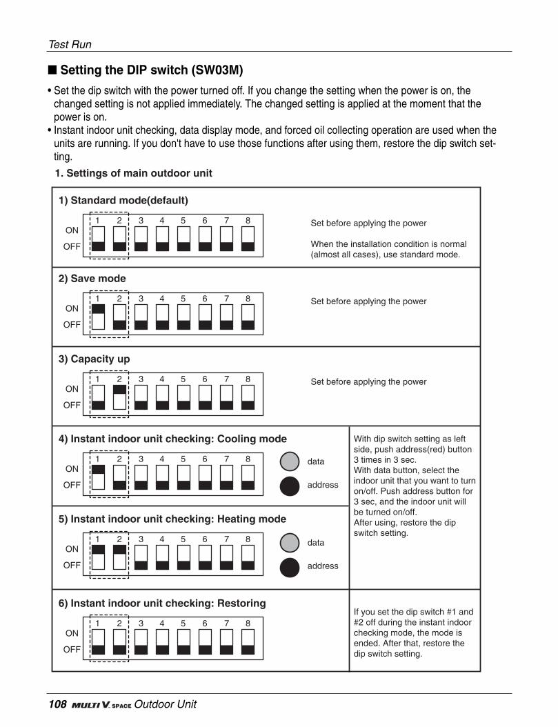
108 Outdoor Unit
Setting the DIP switch (SW03M)
• Set the dip switch with the power turned off. If you change the setting when the power is on, thechanged setting is not applied immediately. The changed setting is applied at the moment that thepower is on.
• Instant indoor unit checking, data display mode, and forced oil collecting operation are used when theunits are running. If you don't have to use those functions after using them, restore the dip switch set-ting.
1. Settings of main outdoor unit
Set before applying the power7 865421 3ON
OFF
3) Capacity up
Set before applying the power7 865421 3ON
OFF
2) Save mode
Set before applying the power
When the installation condition is normal (almost all cases), use standard mode.
7 865421 3ON
OFF
1) Standard mode(default)
7 865421 3ON
OFF
4) Instant indoor unit checking: Cooling mode With dip switch setting as left side, push address(red) button 3 times in 3 sec.With data button, select the indoor unit that you want to turn on/off. Push address button for 3 sec, and the indoor unit will be turned on/off.After using, restore the dip switch setting.
If you set the dip switch #1 and #2 off during the instant indoor checking mode, the mode is ended. After that, restore the dip switch setting.
7 865421 3ON
OFF
5) Instant indoor unit checking: Heating mode
7 865421 3ON
OFF
6) Instant indoor unit checking: Restoring
data
address
data
address
Test Run
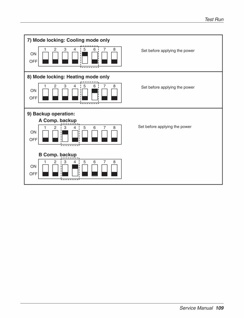
Service Manual 109
Test Run
Set before applying the power7 865421 3ON
OFF
7) Mode locking: Cooling mode only
Set before applying the power7 865421 3ON
OFF
8) Mode locking: Heating mode only
7 865421 3ON
OFF
9) Backup operation: A Comp. backup
B Comp. backup
Set before applying the power
7 865421 3ON
OFF

110 Outdoor Unit
Test Run
Setting the E.S.P (External static pressure)
• Set the connector like the following table when external static pressure is applied on the outdoor unit.If you set the connector, the RPM of outdoor unit's fans will be changed properly.
• Connector (In the bag with installation manual)
• Housing (in the Main PCB)
6) External Static Pressure 12 ~ 14 mmAq
Insert connector on following table
Connector
Connector
Connector
Connector Connector
ConnectorConnector
1) External Static Pressure 0 ~ 3 mmAq
2) External Static Pressure 3 ~ 6 mmAq
3) External Static Pressure 6 ~ 8 mmAq
4) External Static Pressure 8 ~ 10 mmAq
5) External Static Pressure 10 ~ 12 mmAq
CAUTION
- The product may not properly operate if the connector is not properly setup.

Service Manual 111
Replacement procedure for Compressor1) Collect the refrigerant by using refrigerant recov-
ery unit(Since the setting on outdoor unit PCB is required forrefrigerant recovery, refer to the warming plate"Precautions in service work" attached on the switchbox cover)
2) Remove the sound insulator mat covering thefaulty compressor, and disconnect the power
3) Disconnect the brazing sections of suction pipeand discharge pipe by using brazing torch after therefrigerant has been collected completely.
4) Remove equalizing pipe.
5) Remove three bolts at cushion rubber section totake out the faulty compressor outside the unit.
6) Install the new compressor in the unit.(Be sure toinsert the cushion rubbers before tightening thefixing bolts of compressor.)
7) Remove the rubber caps put on the suction anddischarge pipe of the new compressor torelease.the sealing nitrogen gas.(Take note that oilmay spout due to the pipe inside pressure if theplug put on the equalizing seat is removed beforeremoving of rubber cap.)
8) Braze equalizing pipe with nut.
9) Braze the suction and discharge pipe with brazingtorch to the compressor.
Cut section10) Conduct air tight test to check the piping system
is free from leakage.
11) Connect power cable to the terminal board ofcompressor and cover the compressor withsound insulator mat.
12) Conduct vacuum drying.(Since the setting on out-door unit PCB is required for vacuum drying, referto the warning plate recautions in service work”attached on the switch box cover.)
13) Charge refrigerant after the completion of vacuumdrying, and check the function of compressorwith cooling or heating operation.
Replacement procedure for Compressor
Discharge pipe
Suction pipe
Equalizing pipe

112 Outdoor Unit
Service Manual 113
Trouble shooting guide

114 Trouble Shooting Guide
1. The phenomena from main component failure ............................113
2. Checking Method for Key Components
2.1 Compressor............................................................................114
2.2 Fan Motor...............................................................................115
2.3 Linear Expansion Valve ..........................................................116
2.4 3Phase Bridge Diode..............................................................119
2.5 IPM(Integrated Power Module)...................................................120
2.6 Other......................................................................................121
3. Self-diagnosis function ...............................................................122
Trouble shooting guide

The phenomena from main component failure
Service Manual 115
1. The phenomena from main component failureThe phenomena from main component failure
Compressor
Outdoorfan
OutdoorLEV
Not operating
Stop during running
Loud noise duringrunning
High pressure errorat cooling
Heating failure, fre-quent defrosting
No operating soundat applying power
Heating failure,frozen outdoor heatexchanger part
Low pressure erroror discharge temper-ature error
Motor insulation broken
Motor insulation failure
Phase sequence fault
Motor failure,bad ventilation aroundoutdoor heat exchanger
Bad connector contact
Coil failure
LEV clogged
LEV clogged
Check resistance between terminals andchassis
Check resistance between terminals andchassis
Check wiring(R, S, T) sequence, or interchange last two phase connection.
Check the outdoor fan operation after beingturned the outdoor units off for some time.Remove obstacles around the outdoor units
Check connector
Check resistance between terminals
Service necessary
Service necessary
Component Phenomenon Cause Check method and Trouble shooting
When system fault occurs, the error code is displayed at indoor unit display or remote control display, the trou-ble shooting guide is in the service manual
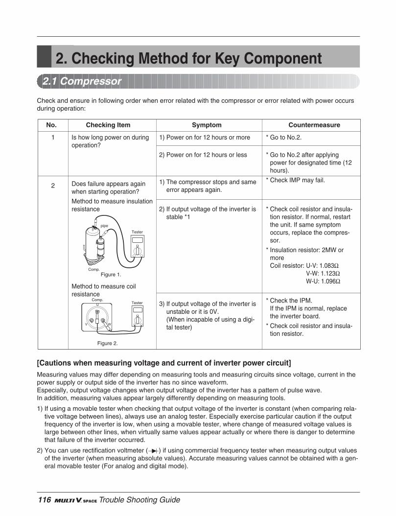
116 Trouble Shooting Guide
2. Checking Method for Key Component2.1 Compressor
Check and ensure in following order when error related with the compressor or error related with power occursduring operation:
[Cautions when measuring voltage and current of inverter power circuit]Measuring values may differ depending on measuring tools and measuring circuits since voltage, current in thepower supply or output side of the inverter has no since waveform.Especially, output voltage changes when output voltage of the inverter has a pattern of pulse wave.In addition, measuring values appear largely differently depending on measuring tools.
1) If using a movable tester when checking that output voltage of the inverter is constant (when comparing rela-tive voltage between lines), always use an analog tester. Especially exercise particular caution if the outputfrequency of the inverter is low, when using a movable tester, where change of measured voltage values islarge between other lines, when virtually same values appear actually or where there is danger to determinethat failure of the inverter occurred.
2) You can use rectification voltmeter ( ) if using commercial frequency tester when measuring output valuesof the inverter (when measuring absolute values). Accurate measuring values cannot be obtained with a gen-eral movable tester (For analog and digital mode).
1
2
Is how long power on duringoperation?
Does failure appears againwhen starting operation?
Method to measure insulationresistance
Method to measure coilresistance
1) Power on for 12 hours or more
2) Power on for 12 hours or less
1) The compressor stops and sameerror appears again.
2) If output voltage of the inverter isstable *1
3) If output voltage of the inverter isunstable or it is 0V.(When incapable of using a digi-tal tester)
* Go to No.2.
* Go to No.2 after applyingpower for designated time (12hours).
* Check IMP may fail.
* Check coil resistor and insula-tion resistor. If normal, restartthe unit. If same symptomoccurs, replace the compres-sor.
* Insulation resistor: 2MW ormoreCoil resistor: U-V: 1.083Ω
V-W: 1.123ΩW-U: 1.096Ω
* Check the IPM.If the IPM is normal, replacethe inverter board.
* Check coil resistor and insula-tion resistor.
No. Checking Item Symptom Countermeasure
Comp.Tester
V
U
W
Ω
Figure 2.
Comp.
pipe
Figure 1.
Ω
Tester
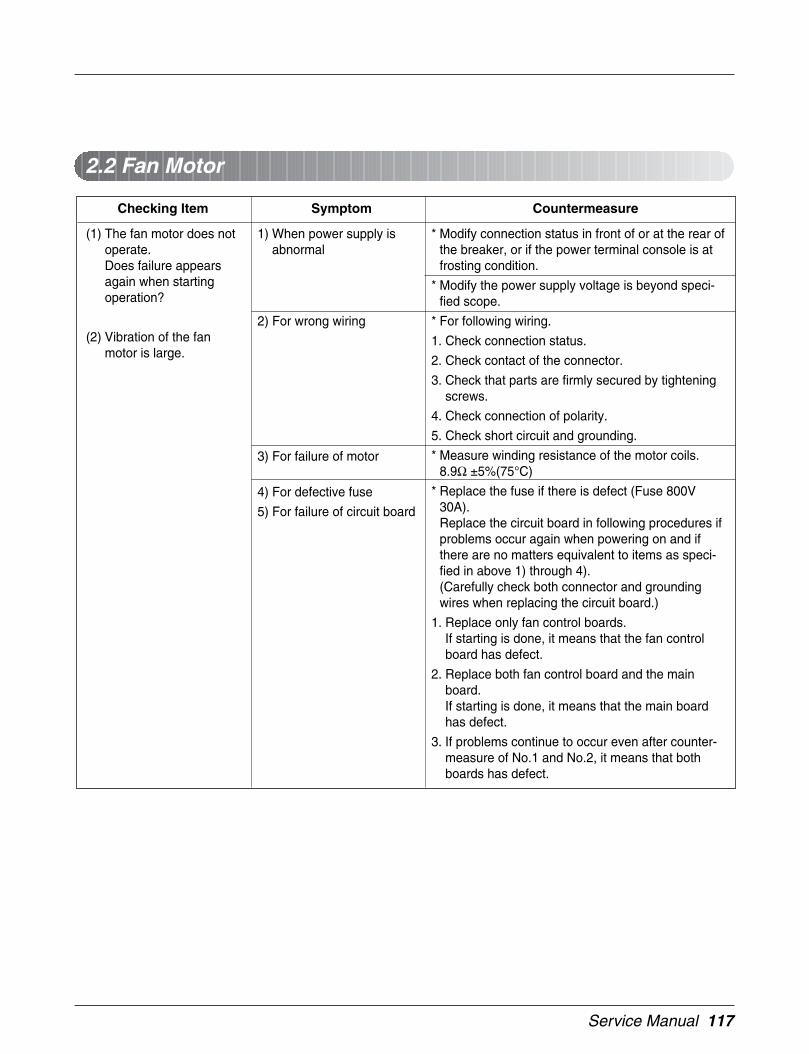
Service Manual 117
2.2 Fan Motor
(1) The fan motor does notoperate.Does failure appearsagain when startingoperation?
(2) Vibration of the fanmotor is large.
1) When power supply isabnormal
2) For wrong wiring
3) For failure of motor
4) For defective fuse
5) For failure of circuit board
* Modify connection status in front of or at the rear ofthe breaker, or if the power terminal console is atfrosting condition.
* Modify the power supply voltage is beyond speci-fied scope.
* For following wiring.
1. Check connection status.
2. Check contact of the connector.
3. Check that parts are firmly secured by tighteningscrews.
4. Check connection of polarity.
5. Check short circuit and grounding.
* Measure winding resistance of the motor coils.8.9Ω ±5%(75°C)
* Replace the fuse if there is defect (Fuse 800V30A).Replace the circuit board in following procedures ifproblems occur again when powering on and ifthere are no matters equivalent to items as speci-fied in above 1) through 4).(Carefully check both connector and groundingwires when replacing the circuit board.)
1. Replace only fan control boards.If starting is done, it means that the fan controlboard has defect.
2. Replace both fan control board and the mainboard.If starting is done, it means that the main boardhas defect.
3. If problems continue to occur even after counter-measure of No.1 and No.2, it means that bothboards has defect.
Checking Item Symptom Countermeasure
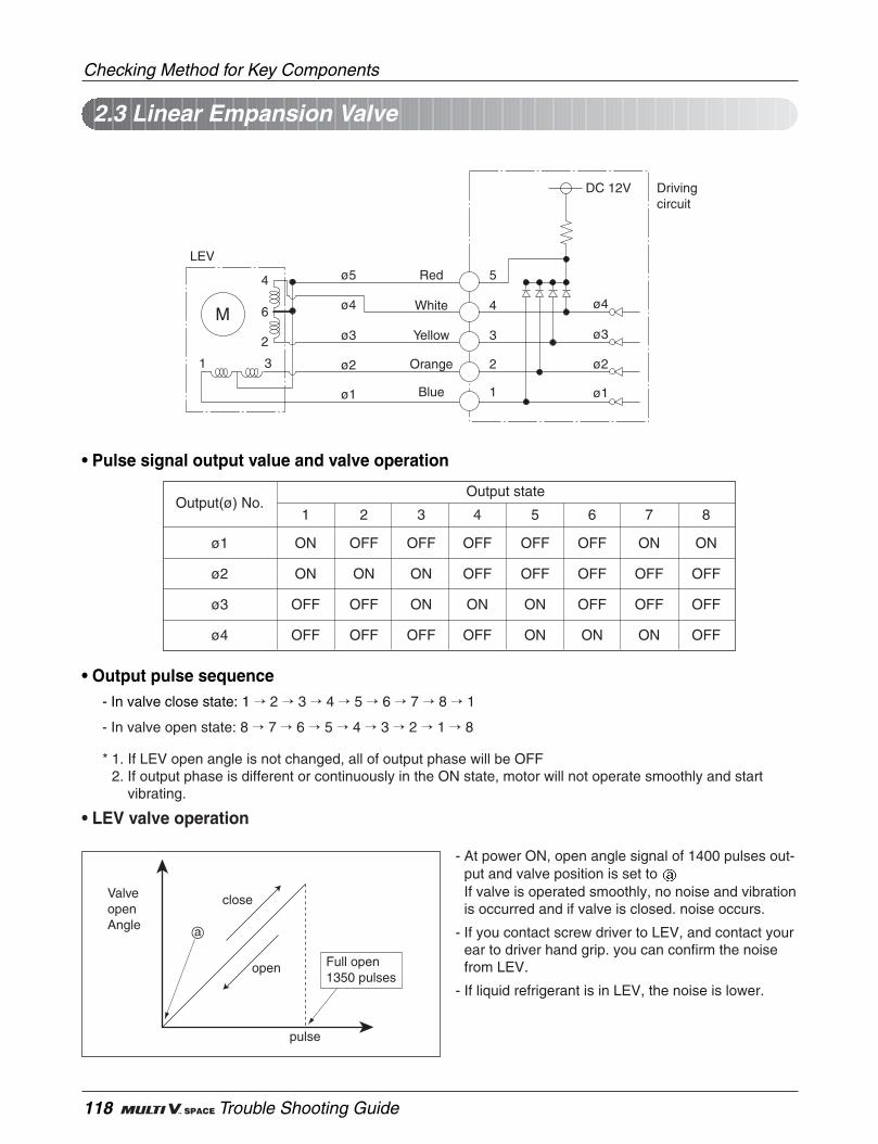
118 Trouble Shooting Guide
Checking Method for Key Components
LEV
M
1 3
2
6
4 ø5 Red
White
Yellow
Orange
Blue
5
4
3
2
ø4
DC 12V Drivingcircuit
ø3
ø2
ø11
ø4
ø3
ø2
ø1
• Pulse signal output value and valve operation
• Output pulse sequence- In valve close state: 1 2 3 4 5 6 7 8 1
- In valve open state: 8 7 6 5 4 3 2 1 8
* 1. If LEV open angle is not changed, all of output phase will be OFF2. If output phase is different or continuously in the ON state, motor will not operate smoothly and start
vibrating.
• LEV valve operation
ø1 ON OFF OFF OFF OFF OFF ON ON
ø2 ON ON ON OFF OFF OFF OFF OFF
ø3 OFF OFF ON ON ON OFF OFF OFF
ø4 OFF OFF OFF OFF ON ON ON OFF
Output(ø) No.Output state
1 2 3 4 5 6 7 8
ValveopenAngle
close
pulse
open Full open1350 pulses
- At power ON, open angle signal of 1400 pulses out-put and valve position is set toIf valve is operated smoothly, no noise and vibrationis occurred and if valve is closed. noise occurs.
- If you contact screw driver to LEV, and contact yourear to driver hand grip. you can confirm the noisefrom LEV.
- If liquid refrigerant is in LEV, the noise is lower.
2.3 Linear Empansion Valve
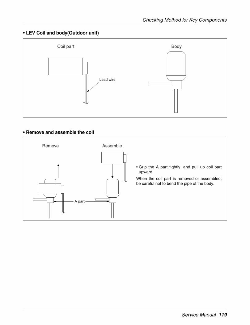
Service Manual 119
Checking Method for Key Components
• LEV Coil and body(Outdoor unit)
• Remove and assemble the coil
Lead wire
Coil part Body
A part
Remove Assemble
• Grip the A part tightly, and pull up coil partupward.
When the coil part is removed or assembled,be careful not to bend the pipe of the body.
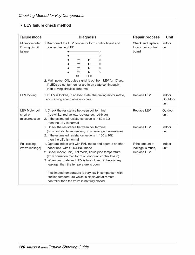
120 Trouble Shooting Guide
Checking Method for Key Components
• LEV failure check method
Failure mode Diagnosis Repair process Unit
MicrocomputerDriving circuitfailure
1.Disconnect the LEV connector form control board and connect testing LED
2. Main power ON, pulse signal is out from LEV for 17 sec. If LEDs do not turn on, or are in on state continuously, then driving circuit is abnormal
Check and replaceIndoor unit controlboard
Indoorunit
LEV locking 1.If LEV is locked, in no load state, the driving motor rotate, and clicking sound always occurs
Replace LEV Indoor/ Outdoorunit
LEV Motor coilshort or misconnection
1. Check the resistance between coil terminal (red-white, red-yellow, red-orange, red-blue) 2. If the estimated resistance value is in 52 ± 3Ω then the LEV is normal
Replace LEV Outdoorunit
1. Check the resistance between coil terminal (brown-white, brown-yellow, brown-orange, brown-blue) 2. If the estimated resistance value is in 150 ± 10Ω then the LEV is normal
Replace LEV Indoorunit
1. Operate indoor unit with FAN mode and operate another indoor unit with COOLING mode 2. Check indoor unit(FAN mode) liquid pipe temperature (from operation monitor of outdoor unit control board)3. When fan rotate and LEV is fully closed, if there is any leakage, then the temperature is down
If estimated temperature is very low in comparison with suction temperature which is displayed at remote controller then the valve is not fully closed
If the amount of leakage is much,Replace LEV
Indoorunit
Full closing(valve leakage)
1K LED
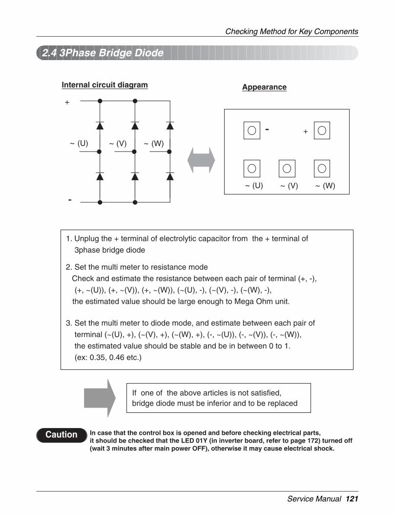
Service Manual 121
Checking Method for Key Components
Appearance
+-
~ (W)~ (V)~ (U)
1. Unplug the + terminal of electrolytic capacitor from the + terminal of
3phase bridge diode
2. Set the multi meter to resistance mode
Check and estimate the resistance between each pair of terminal (+, -),
(+, ~(U)), (+, ~(V)), (+, ~(W)), (~(U), -), (~(V), -), (~(W), -),
the estimated value should be large enough to Mega Ohm unit.
3. Set the multi meter to diode mode, and estimate between each pair of
terminal (~(U), +), (~(V), +), (~(W), +), (-, ~(U)), (-, ~(V)), (-, ~(W)),
the estimated value should be stable and be in between 0 to 1.
(ex: 0.35, 0.46 etc.)
If one of the above articles is not satisfied,bridge diode must be inferior and to be replaced
+
-
~ (U) ~ (V) ~ (W)
Internal circuit diagram
In case that the control box is opened and before checking electrical parts,it should be checked that the LED 01Y (in inverter board, refer to page 172) turned off(wait 3 minutes after main power OFF), otherwise it may cause electrical shock.
Caution
2.4 3Phase Bridge Diode

122 Trouble Shooting Guide
Checking Method for Key Components
P
N
U V W
3 7 11
16 17 18
P
N UVW
1 19Array of IPM Pin
If one of the above articles is not satisfied, IPM must be inferior and is to be replaced
Internal circuit diagram Appearance
1. Unplug the +, – terminal of electrolytic capacitor from the P and N terminal of IPM
2. Set the multi meter to resistance mode Check and estimate the resistance between each pair of terminal (P, N), (P, U), (P, V), (P, W), (U, N), (V, N), (W, N), the estimated value should be large enough to Mega Ohm unit.
3. Set the multi meter to resistance mode Check and estimate the resistance between each pair of terminal(3, U), (7, V), (11, W), (16, N), (17, N), (18, N), the estimated valueshould be large enough to Mega Ohm unit.the check point is inside of the screw hole (U, V, W, N), if check points are plate face of the terminal, then estimated values are gate resistance.
4. Set the multi meter to diode mode, and estimate between each pair of terminal (U, P), (V, P), (W, P), (N, U), (N, V), (N, W), the estimated value should be stable and be in between 0 to 1. (ex: 0.35, 0.46 etc.)
In case that the control box is opened and before checking electrical parts,it should be checked that the LED 01Y (in inverter board, refer to page 172) turned off(wait 3 minutes after main power OFF), otherwise it may cause electrical shock.
Caution
2.5 IPM(Integrated Power Module)

Service Manual 123
Checking Method for Key Components
1) Disconnect an terminal of voltage distribution resistor from each DC link
electrolytic capacitor
2) Set the multi meter to resistance mode, connect the probe to +,- terminal of the capacitor. If the estimated resistance value is increase
continuously without short(value is 0), then the resistor is normal
3) Set the multi meter to resistance mode, confirm that the resistance value
of the resistor is around 270 kOhm
Check and replace inferiorcomponents
Guide of check electrolytic capacitor and resistor for voltage distribution
In case that the control box is opened and before checking electrical parts,it should be checked that the LED 01Y turned off (wait 3 minutes after main powerOFF), otherwise it may cause electrical shock.
Caution
Electrolytic capacitor and resistor for voltage distribution
2.6 Other

124 Trouble Shooting Guide
Self-diagnosis function
3. Self-diagnosis functionSelf-Diagnosis Function
Error Indicator• This function indicates types of failure in self-diagnosis and occurrence of failure for air condition.• Error mark is displayed on display window of indoor units and wired remote controller, and 7-segment LED of
outdoor unit control board as shown in the table.• If more than two troubles occur simultaneously, lower number of error code is first displayed.• After error occurrence, if error is released, error LED is also released simultaneously.
Display Title Cause of Error
0
0
0
0
0
0
0
0
1
2
3
4
5
6
7
8
Air temperature sensor of indoor unit
Inlet pipe temperature sensor of indoor unit
Transmission error : wired remotecontroller ↔ indoor unit
Drain pump
Transmission error : outdoor unit↔ indoor unit
Outlet pipe temperature sensor ofindoor unit
Different operation mode
Indoor LEV
Air temperature sensor of indoor unit is open or short
Inlet pipe temperature sensor of indoor unit is open or short
Failing to receive wired remote controller signal atindoor unit PCB
Malfunction of drain pump
Failing to receive outdoor unit signal at indoor unit PCB
Outlet pipe temperature sensor of indoor unit isopen or short
Operation mode between indoor unit and outdoor unitis different
Malfunction of indoor LEV
Ind
oo
ru
nit
rela
ted
erro
r
2
2
2
2
2
1
2
3
4
5
3
3
3
3
2
3
4
5
DC peak
Overcurrent of inverter comp.
Poor voltage charge for drivingINV compressor
High pressure switch
Low/Over voltage
Discharge temperature(INV compressor A)
Discharge temperature(INV compressor B)
High pressure
Low pressure
IPM fault or overcurrent to compressor
Overcurrent flows to inverter compressor
DC charging is not performed after starting relay turnon
System is off by high pressure switch
Input voltage is out of tolerable range.
System is off due to rising of INV compressor A dischargetemperature
System is off due to rising of INV compressor Bdischarge temperature
System is off by excessive increase of high pressure
System is off by excessive decrease of low pressure
Po
wer
rela
ted
erro
rC
ompr
esso
rre
late
der
ror
Serial No.
Poor fan moto operation
Transmission error : indoor unit main PCB of outdoor.
In the case that the serial number marked on EEP-ROM of indoor unit is 0 or FFFFFF
Disconnecting the fan motor connector/Failure orindoor fan motor lock.
When the addressing signal doesn't come out for 3mins. suddenly, whilethe indoor unit gets the calling signal coming from the outdoor unit.
0 9
1 0
1 1
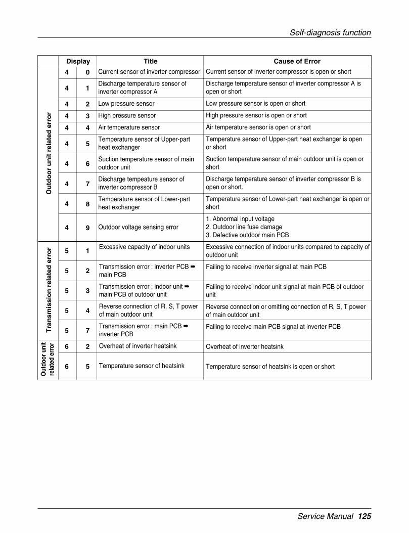
Service Manual 125
Self-diagnosis function
Current sensor of inverter compressor is open or short
Discharge temperature sensor of inverter compressor A isopen or short
Low pressure sensor is open or short
High pressure sensor is open or short
Air temperature sensor is open or short
Temperature sensor of Upper-part heat exchanger is openor short
Suction temperature sensor of main outdoor unit is open orshort
Discharge temperature sensor of inverter compressor B isopen or short.
Temperature sensor of Lower-part heat exchanger is open orshort
1. Abnormal input voltage2. Outdoor line fuse damage3. Defective outdoor main PCB
Current sensor of inverter compressor
Discharge temperature sensor ofinverter compressor A
Low pressure sensor
High pressure sensor
Air temperature sensor
Temperature sensor of Upper-partheat exchanger
Suction temperature sensor of mainoutdoor unit
Discharge tempeature sensor ofinverter compressor B
Temperature sensor of Lower-partheat exchanger
Outdoor voltage sensing error
Display Title Cause of Error
4
4
4
4
4
4
4
4
4
4
0
1
2
3
4
5
6
7
8
9
5
5
5
5
5
6
6
1
2
3
4
7
2
5
Excessive connection of indoor units compared to capacity ofoutdoor unit
Failing to receive inverter signal at main PCB
Failing to receive indoor unit signal at main PCB of outdoorunit
Reverse connection or omitting connection of R, S, T powerof main outdoor unit
Failing to receive main PCB signal at inverter PCB
Overheat of inverter heatsink
Temperature sensor of heatsink is open or short
Excessive capacity of indoor units
Transmission error : inverter PCB main PCB
Transmission error : indoor unit main PCB of outdoor unit
Reverse connection of R, S, T powerof main outdoor unit
Transmission error : main PCB inverter PCB
Overheat of inverter heatsink
Temperature sensor of heatsink
Ou
tdo
or
un
itre
late
der
ror
Tra
nsm
issi
on
rela
ted
erro
rO
utdo
orun
itre
late
der
ror

126 Trouble Shooting Guide
Self-diagnosis function
Please refer to trouble shooting guide in service manual for each error title
CAUTIONIn case that the control box is opened and before checking electrical parts, it should be checked thatthe LED 01M (Refer to next page) turned off (wait 3 minutes after main power OFF), otherwise, it maycause electrical shock.
Failing to receive fan signal at main PCB
Over-current of fan motor (IPM fault)
Low voltage of fan motor driver
Failing to receive main signal at fan PCB
Liquid pipe temperature sensor is open or short
Subcooling inlet temperature sensor is open or short
Subcooling outlet temperature sensor is open or short
Pressure unbalance between outdoor units
Transmission error : fan PCB mainPCB
Over-current of fan motor (IPM fault)
Low voltage of fan motor driver
Transmission error : main PCB fanPCB
Liquid pipe temperature sensor
Subcooling inlet temperature sensor
Subcooling outlet temperature sensor
Failure of operation mode conver-sion
Display Title Cause of Error
1 0 5
1 0 6
1 0 7
1 0 8
1 1 3
1 1 4
1 1 5
1 5 1
Tran
smis
sion
rela
ted
erro
rO
utdo
orun
itre
late
der
ror

Service Manual 127
Troubleshooting Guide
Indoor Unit room temp.sensor error
Unit inlet pipe temp.sensor error(Indoor Unit)
Outlet pipe temp. sensor error(Indoor Unit)
ErrorCode
Error Contents Meaning Main CausesError display
position
01
02
06
Indoor Unitsensor open
or short
ConcernedRemote con-
trollerPanel Display
1. Sensor wrong connection
2. Sensor open/Short
3. Defective Indoor Unit PCB
4. Defective Sensor
Defect inspection method :
1) Check the connecting point of the sensor with the PCB (Sensor's Connector).Is the sensor connecting condition correct ? Otherwise, reconnect the sensor at the correct position.
2) Remove the sensor and measure its resistance with a tester.Room temp sensor : 10°C = 20.7kΩ : 25°C = 10kΩ : 50°C = 3.4kΩPipe temp sensor : 10°C = 10kΩ : 25°C= 5kΩ : 50°C = 1.8kΩ
3) Replace the sensor if it is not having a correct resistance value.
4) If there is no problem with the sensor and the sensor connection then replace the Indoor Unit PCB.
• Panel Display indication method : Error code and the LED blinking counts are indication.
Communication errorbetween Indoor Unit andthe Wired RemoteController
ErrorCode
Error Contents Meaning Main CausesError display
position
03
In case the wiredRemote Controllercant receive the
the signal from theIndoor Unit
ConcernedRemote
Controller
Panel Display
1. Defective wired Remote controller.
2. Defective Indoor Unit PCB .
3. Defective Connector connection
4. Defective wire of the Wired RemoteController
Defect inspection method :
1) Check the connection point of the Wired Remote Controller (Connecting Connector).
2) In case the Wired Remote Controller's cable is installed near the AC power line, then they must be separated bydistance of at least 30cm.
3) In case the replaced Remote Controller has no defect, then the originally installed Remote Controller is defec-tive.
4) In case the error code exists even after the replacement of the Remote Controller, then the Remote Controller isnot defective and hence only Indoor Unit PCB should be replaced.
5) In case error code exists even after the replacement of the Wired Remote Controller and the Indoor Unit PCB,then replace the cable connecting the Wired Remote Controller and Indoor Unit.

Troubleshooting Guide
128 Indoor Unit
Indoor Unit drainpump error
ErrorCode
Error Contents Meaning Main CausesError display
position
04
In case of the Indoor Unitdrain pump defect the con-
densed water level rises andfloat switch (sensor) detects
the error .
ConcernedRemote controller
Panel Display
1. Defective drain pump / float switch
2. Defective drain (hose chocked /improper inclination )
3. Defective PCB in the Indoor Unit
Defect inspection method :
1) Check the proper functioning of the drain pump in case of any drain water? (Functioning sound / check thewater flowing)
2) In case the drain pump is not working properly, then check the 220V power supply at the drain pump terminalwith a tester.In case the drain pump do not function properly after power supply to the to the PCB, then replace the drainpump.
3) In case of no power at the PCB terminal, then replace the Indoor Unit PCB.
4) In case the drain pump is OK, then check whether the hose is chocked or the drain pipe is improper and makesure to correct the drain flow error if any.
5) In case the drain pump is OK and there is no drain water in drain pan and still the error code is displayed?Then check whether the float sensor is touching the chassis. In case the float switch sensor is not touching thechassis and still the error code exists, then the float switch has the error. In such a case, the drain pumpassembly must be replaced.
Drain Pump connector
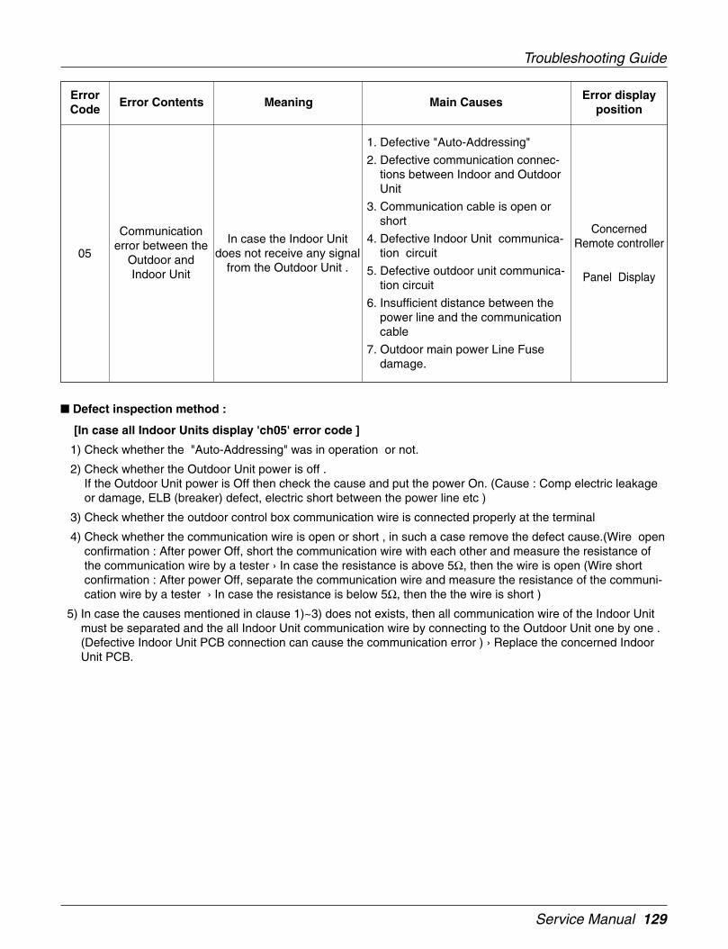
Service Manual 129
Troubleshooting Guide
Communicationerror between the
Outdoor andIndoor Unit
ErrorCode
Error Contents Meaning Main CausesError display
position
05In case the Indoor Unit
does not receive any signalfrom the Outdoor Unit .
ConcernedRemote controller
Panel Display
1. Defective "Auto-Addressing"
2. Defective communication connec-tions between Indoor and OutdoorUnit
3. Communication cable is open orshort
4. Defective Indoor Unit communica-tion circuit
5. Defective outdoor unit communica-tion circuit
6. Insufficient distance between thepower line and the communicationcable
7. Outdoor main power Line Fusedamage.
Defect inspection method :
[In case all Indoor Units display 'ch05' error code ]
1) Check whether the "Auto-Addressing" was in operation or not.
2) Check whether the Outdoor Unit power is off .If the Outdoor Unit power is Off then check the cause and put the power On. (Cause : Comp electric leakageor damage, ELB (breaker) defect, electric short between the power line etc )
3) Check whether the outdoor control box communication wire is connected properly at the terminal
4) Check whether the communication wire is open or short , in such a case remove the defect cause.(Wire openconfirmation : After power Off, short the communication wire with each other and measure the resistance ofthe communication wire by a tester › In case the resistance is above 5Ω, then the wire is open (Wire shortconfirmation : After power Off, separate the communication wire and measure the resistance of the communi-cation wire by a tester › In case the resistance is below 5Ω, then the the wire is short )
5) In case the causes mentioned in clause 1)~3) does not exists, then all communication wire of the Indoor Unitmust be separated and the all Indoor Unit communication wire by connecting to the Outdoor Unit one by one .(Defective Indoor Unit PCB connection can cause the communication error ) › Replace the concerned IndoorUnit PCB.
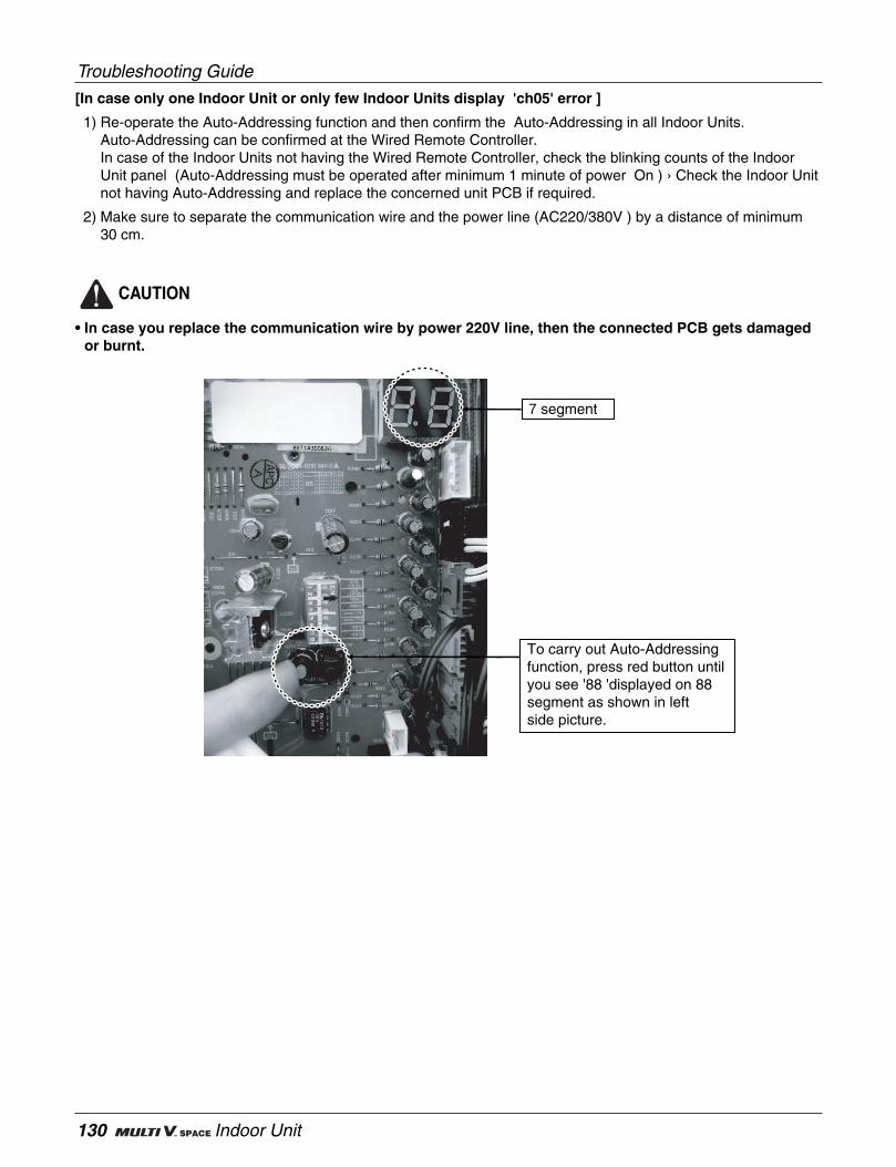
Troubleshooting Guide
130 Indoor Unit
[In case only one Indoor Unit or only few Indoor Units display 'ch05' error ]
1) Re-operate the Auto-Addressing function and then confirm the Auto-Addressing in all Indoor Units.Auto-Addressing can be confirmed at the Wired Remote Controller.In case of the Indoor Units not having the Wired Remote Controller, check the blinking counts of the IndoorUnit panel (Auto-Addressing must be operated after minimum 1 minute of power On ) › Check the Indoor Unitnot having Auto-Addressing and replace the concerned unit PCB if required.
2) Make sure to separate the communication wire and the power line (AC220/380V ) by a distance of minimum30 cm.
CAUTION
• In case you replace the communication wire by power 220V line, then the connected PCB gets damagedor burnt.
To carry out Auto-Addressing function, press red button until you see '88 'displayed on 88 segment as shown in left side picture.
7 segment
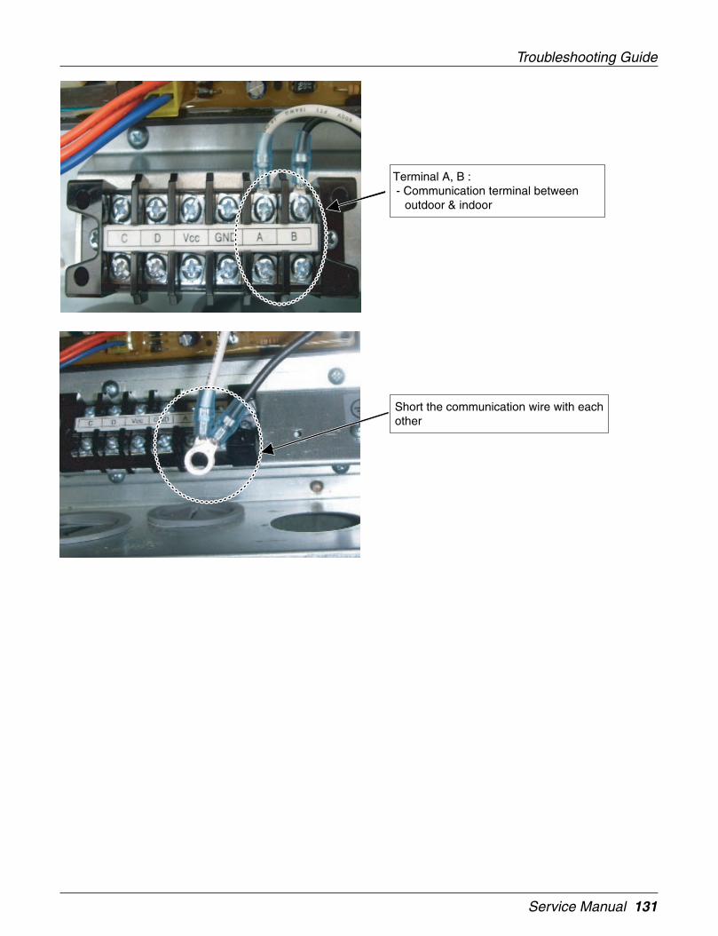
Service Manual 131
Troubleshooting Guide
Short the communication wire with each other
Terminal A, B : - Communication terminal between
outdoor & indoor

Troubleshooting Guide
132 Indoor Unit
Measure resistance
Communication terminal In the indoor.
Communication wire & terminal in the outdoor
Communication wire & terminal in the indoor

Service Manual 133
Troubleshooting Guide
Indoor Unit outletpipe temp. sensor
error
ErrorCode
Error Contents Meaning Main CausesError display
position
06Indoor Unit sensor open
or shortRefer to CH01
All Indoor Unitsare not running in
the samemode(All units
must run either inheating or cooling
mode )
ErrorCode
Error Contents Meaning Main CausesError display
position
07
The Indoor Unit later start-ed is in different modethan the unit started at
first .
ConcernedRemote controller
Panel Display
1. The Indoor Units are in a differentoperation mode.
2. The error display will be in theWired Remote Controller of theunit stared later.
Indoor Unit EEP-ROM error
ErrorCode
Error Contents Meaning Main CausesError display
position
09Problem developed in theEEPROM inside the PCB
of the Indoor Unit
ConcernedRemote controller
Panel Display
1. Error developed in communicationbetween the Microprocessor andthe EEPROM on the surface of thePCB.
2. ERROR due to the EEPROMdamage
Defect inspection method :
1) Error removal method : Press the On/Off button on the Wired Remote controller. The error code will be removedautomatically after a few seconds.
2) Immediately change the operation mode after the pressing the On/Off button. (The same operation mode as inthe original Indoor Unit started at first (other than the defective unit mode) (heating /cooling )
Defect inspection method :
1) Check whether there is some stains at the EEPROM PIN (Lead remnants) .Remove this unwanted material and re-operate the "Auto-Addressing".
2) Replace the Indoor Unit PCB.
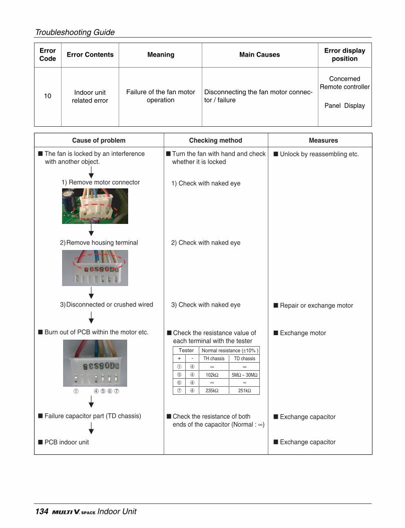
Troubleshooting Guide
134 Indoor Unit
Indoor unitrelated error
ErrorCode
Error Contents Meaning Main CausesError display
position
10Failure of the fan motor
operation
ConcernedRemote controller
Panel Display
Disconnecting the fan motor connec-tor / failure
Burn out of PCB within the motor etc.
The fan is locked by an interference with another object.
Failure capacitor part (TD chassis)
➀ ➃ ➄ ➅ ➆
3) Disconnected or crushed wired
2) Remove housing terminal
1) Remove motor connector
PCB indoor unit
Unlock by reassembling etc.
Turn the fan with hand and checkwhether it is locked
1) Check with naked eye
2) Check with naked eye
3) Check with naked eye Repair or exchange motor
Exchange motor Check the resistance value ofeach terminal with the tester
Check the resistance of both ends of the capacitor (Normal : ∞)
Exchange capacitor
Exchange capacitor
Checking method Measures
√fl∞°
Cause of problem Checking method Measures
Normal resistance (±10% )+ - TH chassis TD chassis
➃
➃
➃
➃
➀
➄
➅
➆
Tester
∞ ∞102kΩ 5MΩ ~ 30MΩ
∞ ∞235kΩ 251kΩ

Service Manual 135
Troubleshooting Guide
Indoor unitrelated error
ErrorCode
Error Contents Meaning Main CausesError display
position
11Outdoor unit cannot
recognize the indoor unit
ConcernedRemote controller
Panel Display
Auto addressing does not work afterexchanging to new PCB
Auto addressing for outdoor unit
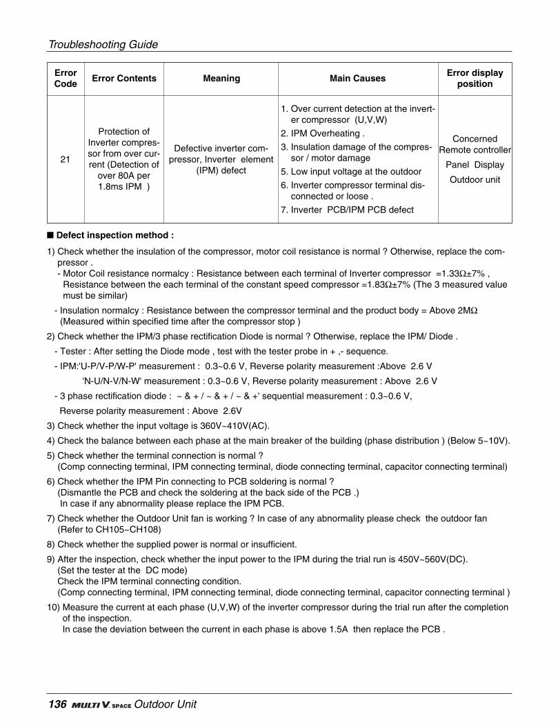
Troubleshooting Guide
136 Outdoor Unit
Protection ofInverter compres-sor from over cur-rent (Detection of
over 80A per1.8ms IPM )
ErrorCode
Error Contents Meaning Main CausesError display
position
21Defective inverter com-
pressor, Inverter element(IPM) defect
ConcernedRemote controller
Panel Display
Outdoor unit
1. Over current detection at the invert-er compressor (U,V,W)
2. IPM Overheating .
3. Insulation damage of the compres-sor / motor damage
5. Low input voltage at the outdoor
6. Inverter compressor terminal dis-connected or loose .
7. Inverter PCB/IPM PCB defect
Defect inspection method :
1) Check whether the insulation of the compressor, motor coil resistance is normal ? Otherwise, replace the com-pressor .- Motor Coil resistance normalcy : Resistance between each terminal of Inverter compressor =1.33Ω±7% ,
Resistance between the each terminal of the constant speed compressor =1.83Ω±7% (The 3 measured valuemust be similar)
- Insulation normalcy : Resistance between the compressor terminal and the product body = Above 2MΩ(Measured within specified time after the compressor stop )
2) Check whether the IPM/3 phase rectification Diode is normal ? Otherwise, replace the IPM/ Diode .
- Tester : After setting the Diode mode , test with the tester probe in + ,- sequence.
- IPM:'U-P/V-P/W-P' measurement : 0.3~0.6 V, Reverse polarity measurement :Above 2.6 V
'N-U/N-V/N-W' measurement : 0.3~0.6 V, Reverse polarity measurement : Above 2.6 V
- 3 phase rectification diode : ~ & + / ~ & + / ~ & +' sequential measurement : 0.3~0.6 V,
Reverse polarity measurement : Above 2.6V
3) Check whether the input voltage is 360V~410V(AC).
4) Check the balance between each phase at the main breaker of the building (phase distribution ) (Below 5~10V).
5) Check whether the terminal connection is normal ?(Comp connecting terminal, IPM connecting terminal, diode connecting terminal, capacitor connecting terminal)
6) Check whether the IPM Pin connecting to PCB soldering is normal ?(Dismantle the PCB and check the soldering at the back side of the PCB .)In case if any abnormality please replace the IPM PCB.
7) Check whether the Outdoor Unit fan is working ? In case of any abnormality please check the outdoor fan(Refer to CH105~CH108)
8) Check whether the supplied power is normal or insufficient.
9) After the inspection, check whether the input power to the IPM during the trial run is 450V~560V(DC).(Set the tester at the DC mode)Check the IPM terminal connecting condition.(Comp connecting terminal, IPM connecting terminal, diode connecting terminal, capacitor connecting terminal )
10) Measure the current at each phase (U,V,W) of the inverter compressor during the trial run after the completionof the inspection.In case the deviation between the current in each phase is above 1.5A then replace the PCB .

Service Manual 137
Troubleshooting Guide
Resistance measure between phases of compressor
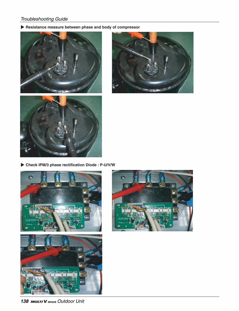
Troubleshooting Guide
138 Outdoor Unit
Resistance measure between phase and body of compressor
Check IPM/3 phase rectification Diode : P-U/V/W
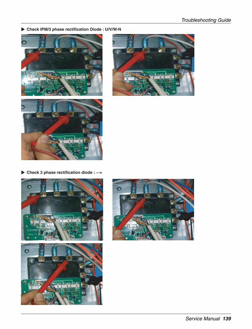
Service Manual 139
Troubleshooting Guide
Check IPM/3 phase rectification Diode : U/V/W-N
Check 3 phase rectification diode : ~-+
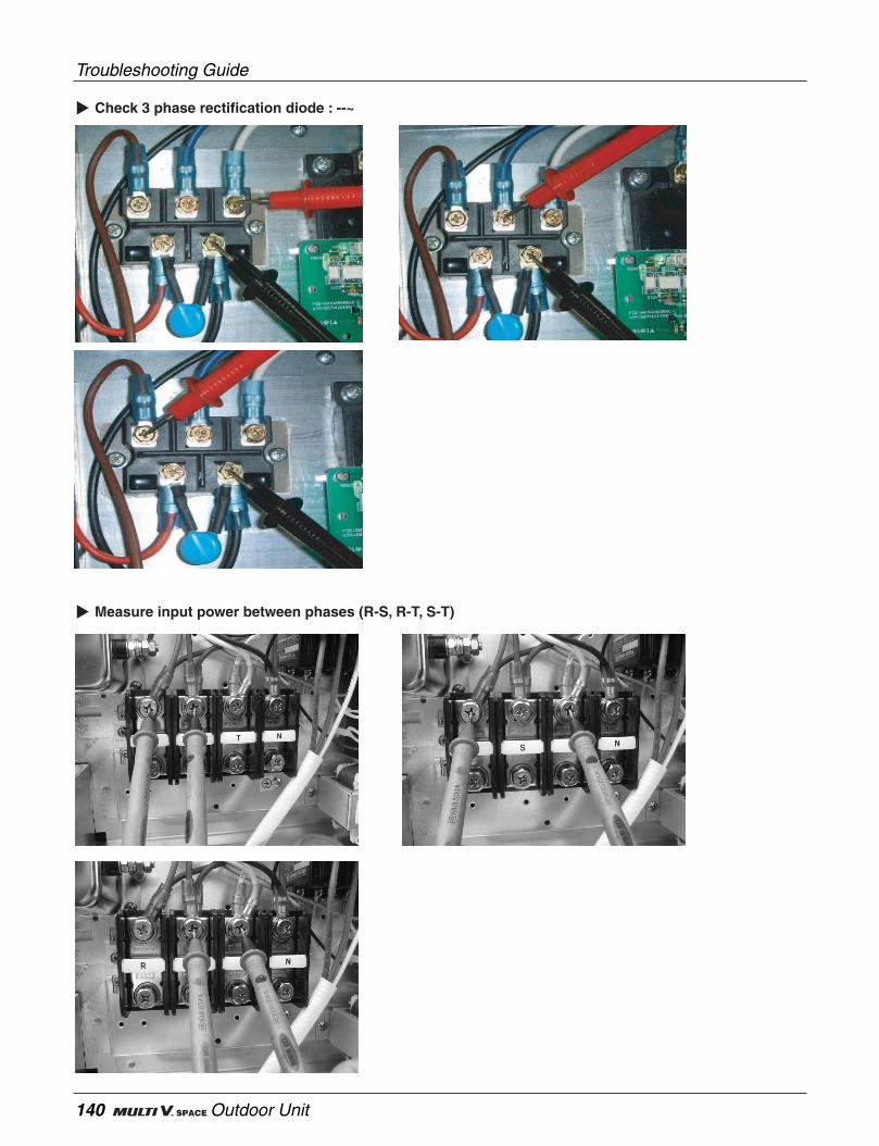
Troubleshooting Guide
140 Outdoor Unit
Check 3 phase rectification diode : --~
Measure input power between phases (R-S, R-T, S-T)
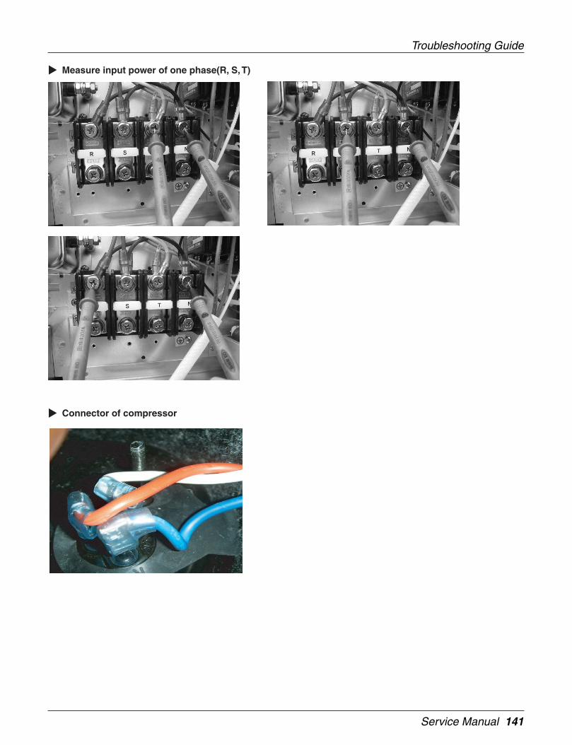
Service Manual 141
Troubleshooting Guide
Measure input power of one phase(R, S, T)
Connector of compressor
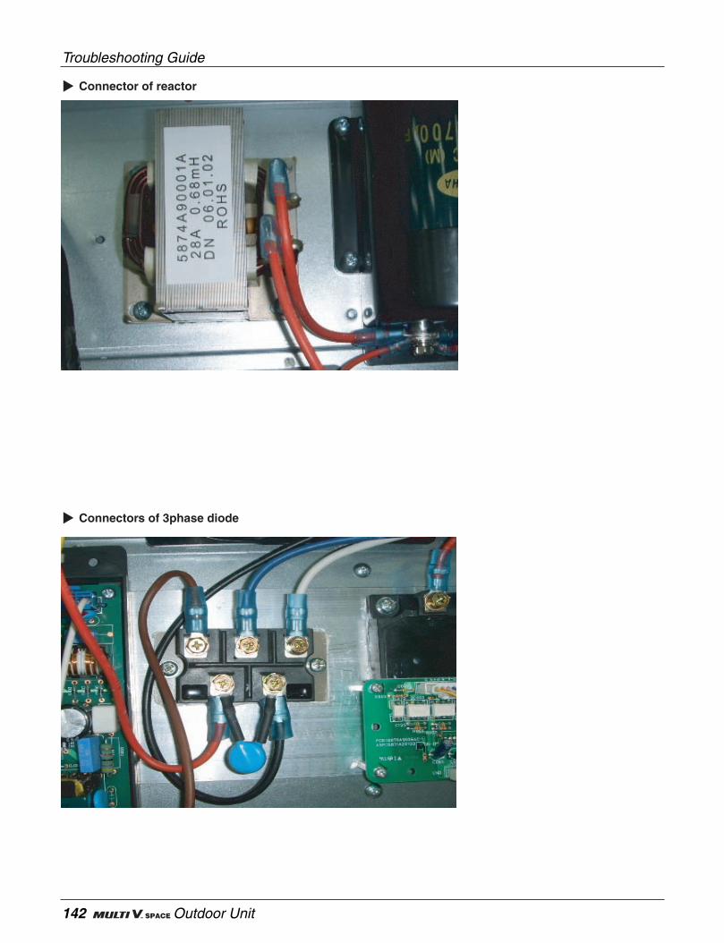
Troubleshooting Guide
142 Outdoor Unit
Connector of reactor
Connectors of 3phase diode
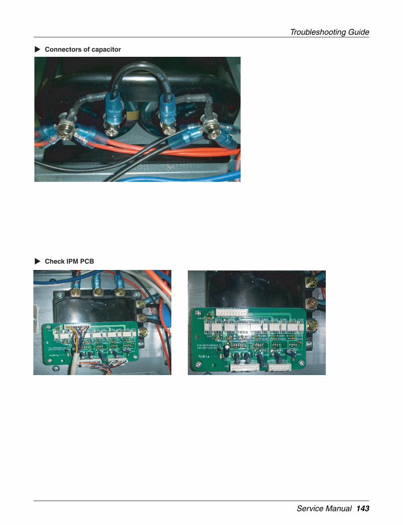
Service Manual 143
Troubleshooting Guide
Connectors of capacitor
Check IPM PCB

Troubleshooting Guide
144 Outdoor Unit
Measure current of IPM U-V-W
Measure voltage of IPM P-N
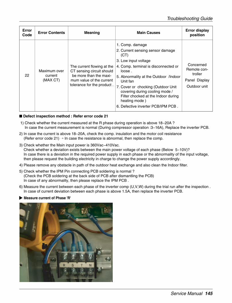
Service Manual 145
Troubleshooting Guide
Maximum overcurrent
(MAX CT)
ErrorCode
Error Contents Meaning Main CausesError display
position
22
The current flowing at theCT sensing circuit shouldbe more than the maxi-
mum value of the currenttolerance for the product .
ConcernedRemote con-
troller
Panel Display
Outdoor unit
1. Comp. damage
2. Current sensing sensor damage(CT)
3. Low input voltage
4. Comp. terminal is disconnected orloose .
5. Abnormality at the Outdoor /IndoorUnit fan
7. Cover or chocking (Outdoor Unitcovering during cooling mode /Filter chocked at the Indoor duringheating mode )
6. Defective inverter PCB/IPM PCB .
Defect inspection method : Refer error code 21
1) Check whether the current measured at the R phase during operation is above 18~20A ?In case the current measurement is normal (During compressor operation :3~16A), Replace the inverter PCB.
2) In case the current is above 18~20A, check the comp. insulation and the motor coil resistance(Refer error code 21) In case the resistance is abnormal, then replace the comp.
3) Check whether the Main input power is 360Vac~410Vac.Check whether a deviation exists between the main power voltage of each phase (Below 5~10V)?In case there is a deviation in the required power supply in each phase or the abnormality of the input voltage,then please request the building electricity in charge to change the power supply accordingly.
4) Please remove any obstacle in path of the outdoor heat exchange and also clean the Indoor filter.
5) Check whether the IPM Pin connecting PCB soldering is normal ?(Check the PCB soldering at the back side of PCB after dismantling the PCB)In case of any abnormality, then please replace the IPM PCB .
6) Measure the current between each phase of the inverter comp (U,V,W) during the trial run after the inspection .In case of current deviation between each phase is above 1.5A, then replace the inverter PCB.
Measure current of Phase 'R'
Troubleshooting Guide
146 Outdoor Unit
Inverter comp. dri-ving voltage
charging defect
ErrorCode
Error Contents Meaning Main CausesError display
position
23Problem in DC chargingvoltage after operating
relay On
ConcernedRemote con-
troller
Panel Display
Outdoor unit
1. Looseness of DC link terminal .
2. Damage operating relay
3. Capacitor damage
4. Three phase current diode damage
5. Abnormal power voltage
6. IPM damage
7. Defective sensing circuit of theinvert PCB
Defect inspection method : Refer error code 21
1) Check whether the starting relay / magnetic contactor at the control box are normal ?(After about 30 seconds of operation the voltage at the IPM P/N terminal should be above 450Vdc)
2) In case the voltage is below 450Vdc,- Make sure that the outdoor main input voltage is (360Vac~410Vac),- Make sure that the magnetic contactor coil resistance (400~700Ω) when the power is Off and also check the
connecting conditions,
- Check whether the comp capacitor connection and the outer shape is normal.(In case of any abnormality there is a shape change or expansion of the capacitor outer body )
3) Compressor insulation and the coil resistance and 3 phase rectification diode should also be checked.(Refer error code 21).
4) In case the error code is still displayed after solving the issue from clause 1)~3), then replace the inverter PCB.

Service Manual 147
Troubleshooting Guide
Measure resistance of magnetic contactor coil
Capacitor of compressor
Inverter IPM P-N connector of IPM
Troubleshooting Guide
148 Outdoor Unit
Excessive rise inoutdoor high
pressure
ErrorCode
Error Contents Meaning Main CausesError display
position
24Compressor Off due to the
high pressure switch inoutdoor unit
ConcernedRemote con-
troller
Panel Display
Outdoor unit
1. Defective high pressure switch
2. Defective Indoor or Outdoor fan
3. Chocked compressor check valve
4. Pipe chocked due to the pipe dam-age
5. Refrigerant overcharge
6. Defective LEV at the Indoor orOutdoor Unit .
7. Covering or chocking (Outdoor cov-ering during the cooling mode /Indoor Unit filter chocking duringthe heating mode)
8. SVC valve chocking
9. Defective Outdoor PCB
Defect inspection method
1) In case the Indoor / Outdoor Unit fan is not working normally, please check and replace them if required.(Refer to CH105~CH108)
2) Check whether Indoor / Outdoor Unit heat exchange is being accomplished successfully.Otherwise, check and modify the installation condition as per the required heat exchange.In case of heat exchanger covering please remove the outdoor condenser covering and also check the IndoorUnit filter.
3) Is the actual pressure reached high enough for the high pressure switch to be operational.Connect the manifold gauge at the high pressure service valve and compare the value of the high pressuresensor.
4) Check whether the SVC valve is open and other conditions(fold, dent etc) .
5) In case the pressure is not high enough for the high pressure switch to come into action, then please check thehigh pressure switch.In case, after temporary shorting of the pressure switch of the inverter and constant speed compressor on oneby one if there is no error code display, then please replace the concerned high pressure switch.In case the error code is displayed after shorting the high pressure switch, then please replace the concernedPCB.
6) Required refrigerant re-calculation and check the refrigerant recharging condition.
7) Check whether the temperature of the both ends of the check valve are similar ?In case a temperature difference is sensed, then please replace the check valve.
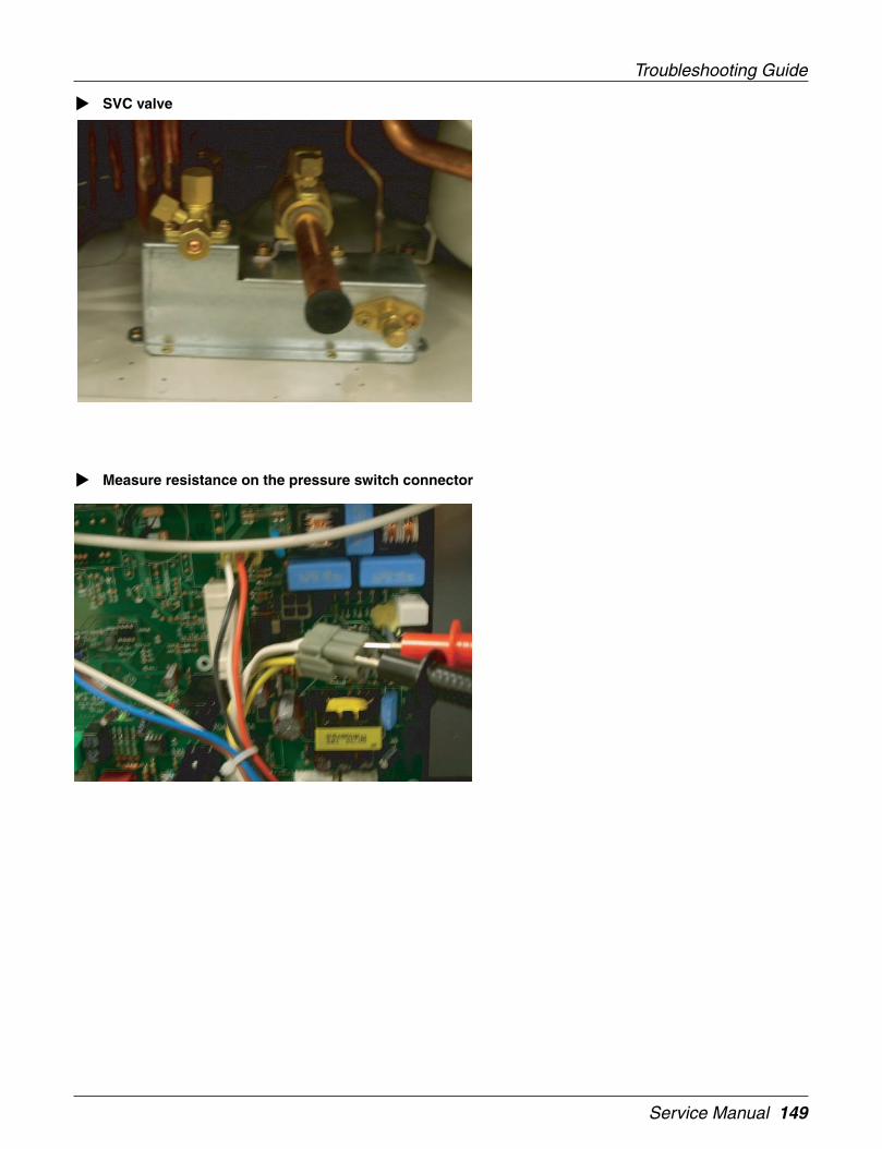
Service Manual 149
Troubleshooting Guide
SVC valve
Measure resistance on the pressure switch connector
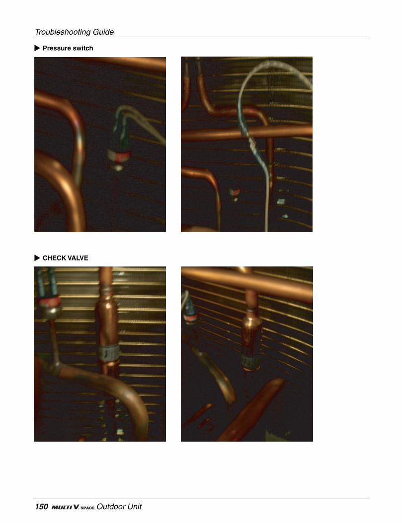
Troubleshooting Guide
150 Outdoor Unit
Pressure switch
CHECK VALVE
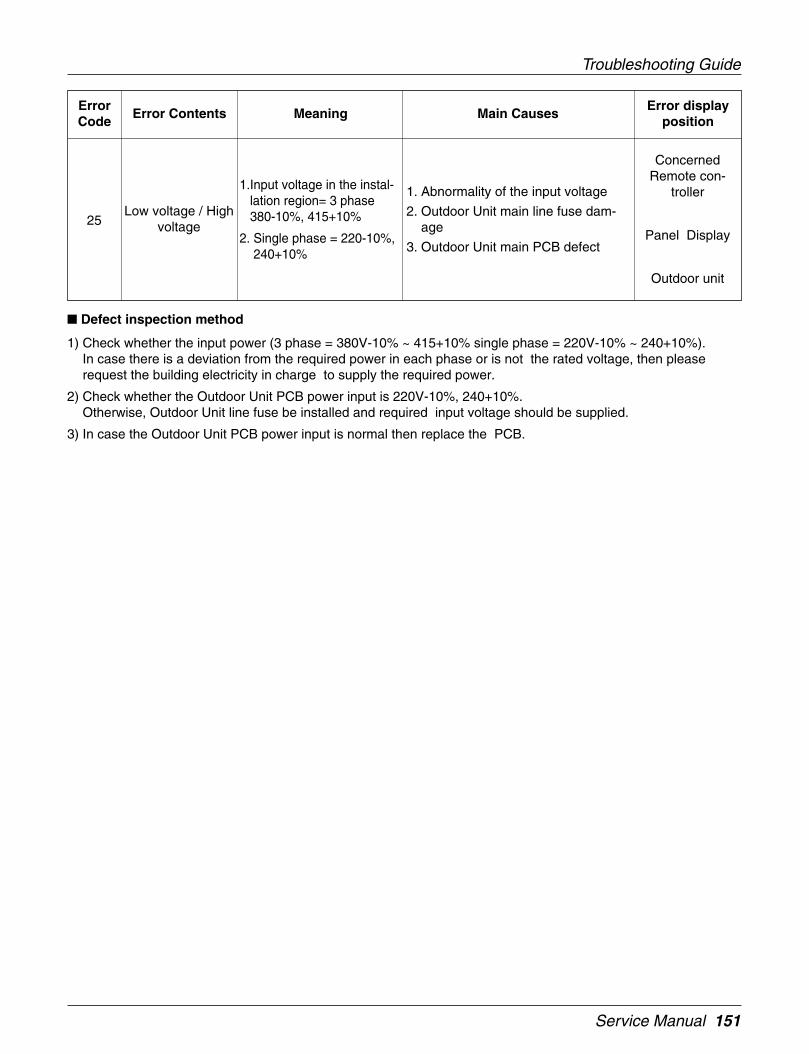
Service Manual 151
Troubleshooting Guide
Low voltage / Highvoltage
ErrorCode
Error Contents Meaning Main CausesError display
position
25
1.Input voltage in the instal-lation region= 3 phase380-10%, 415+10%
2. Single phase = 220-10%,240+10%
ConcernedRemote con-
troller
Panel Display
Outdoor unit
1. Abnormality of the input voltage
2. Outdoor Unit main line fuse dam-age
3. Outdoor Unit main PCB defect
Defect inspection method
1) Check whether the input power (3 phase = 380V-10% ~ 415+10% single phase = 220V-10% ~ 240+10%).In case there is a deviation from the required power in each phase or is not the rated voltage, then pleaserequest the building electricity in charge to supply the required power.
2) Check whether the Outdoor Unit PCB power input is 220V-10%, 240+10%.Otherwise, Outdoor Unit line fuse be installed and required input voltage should be supplied.
3) In case the Outdoor Unit PCB power input is normal then replace the PCB.
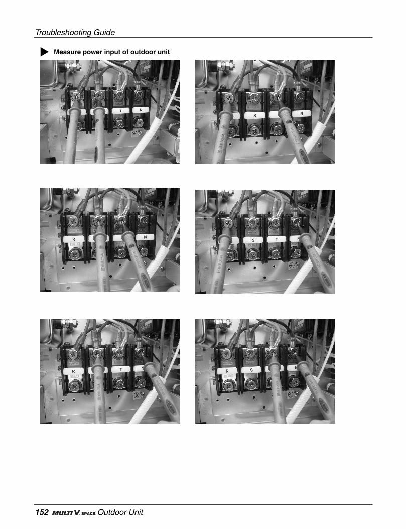
Troubleshooting Guide
152 Outdoor Unit
Measure power input of outdoor unit

Service Manual 153
Troubleshooting Guide
Measure power input of outdoor unit

Troubleshooting Guide
154 Outdoor Unit
Excessive rise ofthe invertercomp.(A)
discharge temp .
ErrorCode
Error Contents Meaning Main CausesError display
position
32Inverter comp. Off due tothe excessive rise in dis-
charge temp
ConcernedRemote con-
troller
Panel Display
Outdoor unit
1. Inverter comp. discharge temp.sensor defect
2. Refrigerant shortage / leakage
3. Defective LEV
4. Defective Liquid Injection Valve
5. Defective Hot Gas Bypass Valve
Defect inspection method :
1) In case there is no actual rise of the discharge temp of the inverter comp.(A) but the sensor shows abnormalrise of the temp, then please replace the discharge pipe sensor
- Discharge temp sensor 10°C = 362kΩ, 25°C = 200kΩ,50°C = 82kΩ, 100°C = 18.5kΩ
In case there is no actual rise of the discharge temp of the inverter comp.(A),then please replace the outdoor MAIN PCB.
2) Check the indoor / outdoor LEV / Hot gas / Liquid Injection valve connector connecting condition.
Excessive rise ofthe invertercomp.(B)
discharge temp .
ErrorCode
Error Contents Meaning Main CausesError display
position
33Inverter comp. Off due tothe excessive rise in dis-
charge temp
ConcernedRemote con-
troller
Panel Display
Outdoor unit
1. Inverter comp. discharge temp.sensor defect
2. Refrigerant shortage / leakage
3. Defective LEV
4. Defective Liquid Injection Valve
5. Defective Hot Gas Bypass Valve
Defect inspection method :
1) In case there is no actual rise of the discharge temp of the inverter comp.(B) but the sensor shows abnormalrise of the temp, then please replace the discharge pipe sensor
- Discharge temp sensor 10°C = 362kΩ, 25°C = 200kΩ,50°C = 82kΩ, 100°C = 18.5kΩ
In case there is no actual rise of the discharge temp of the inverter comp.(B),then please replace the outdoor MAIN PCB.
2) Check the indoor / outdoor LEV / Hot gas / Liquid Injection valve connector connecting condition.
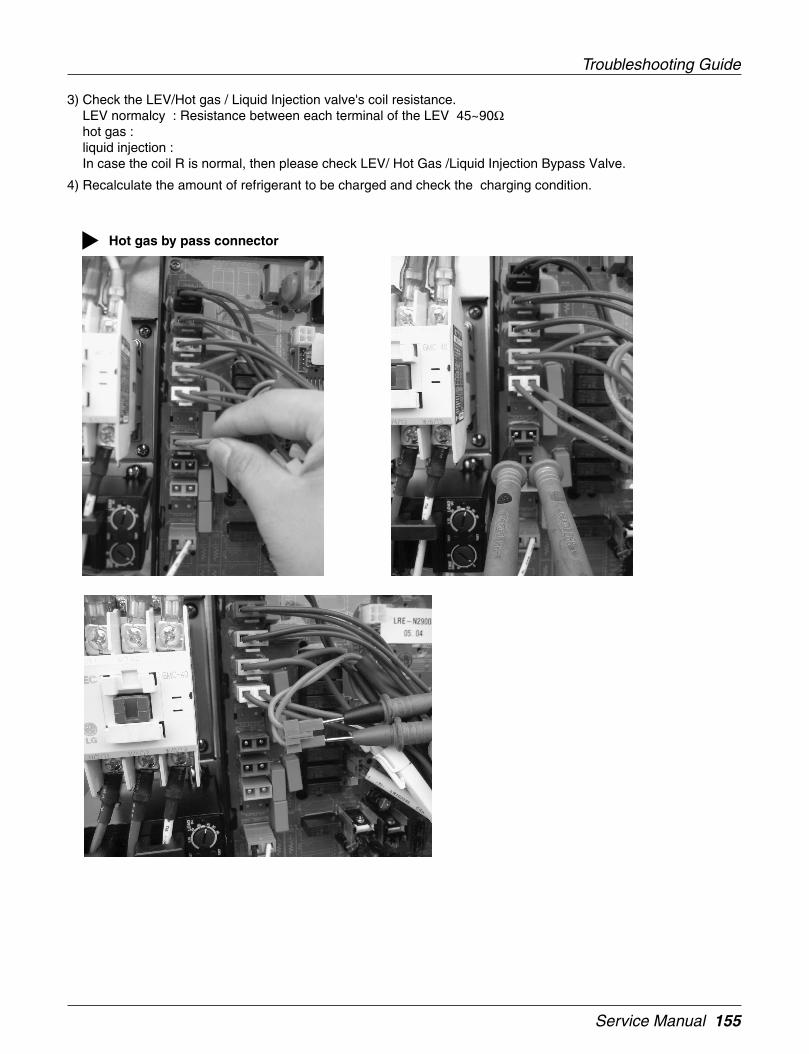
Service Manual 155
Troubleshooting Guide
3) Check the LEV/Hot gas / Liquid Injection valve's coil resistance.LEV normalcy : Resistance between each terminal of the LEV 45~90Ωhot gas :liquid injection :In case the coil R is normal, then please check LEV/ Hot Gas /Liquid Injection Bypass Valve.
4) Recalculate the amount of refrigerant to be charged and check the charging condition.
Hot gas by pass connector

Troubleshooting Guide
156 Outdoor Unit
Liquid injection by pass valve

Service Manual 157
Troubleshooting Guide
Measure resistance of LEV coil

Troubleshooting Guide
158 Outdoor Unit
Heater
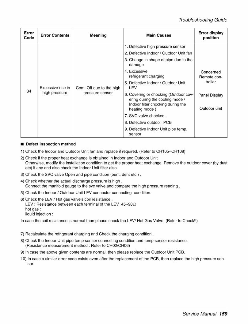
Service Manual 159
Troubleshooting Guide
Excessive rise inhigh pressure
ErrorCode
Error Contents Meaning Main CausesError display
position
34Com. Off due to the high
pressure sensor
ConcernedRemote con-
troller
Panel Display
Outdoor unit
1. Defective high pressure sensor
2. Defective Indoor / Outdoor Unit fan
3. Change in shape of pipe due to thedamage
4. Excessiverefrigerant charging
5. Defective Indoor / Outdoor UnitLEV
6. Covering or chocking (Outdoor cov-ering during the cooling mode /Indoor filter chocking during theheating mode )
7. SVC valve chocked .
8. Defective outdoor PCB
9. Defective Indoor Unit pipe temp.sensor
Defect inspection method
1) Check the Indoor and Outdoor Unit fan and replace if required. (Refer to CH105~CH108)
2) Check if the proper heat exchange is obtained in Indoor and Outdoor UnitOtherwise, modify the installation condition to get the proper heat exchange. Remove the outdoor cover (by dustetc) if any and also check the Indoor Unit filter also.
3) Check the SVC valve Open and pipe condition (bent, dent etc ) .
4) Check whether the actual discharge pressure is high .Connect the manifold gauge to the svc valve and compare the high pressure reading .
5) Check the Indoor / Outdoor Unit LEV connector connecting condition.
6) Check the LEV / Hot gas valve's coil resistance .LEV : Resistance between each terminal of the LEV 45~90Ωhot gas :liquid injection :
In case the coil resistance is normal then please check the LEV/ Hot Gas Valve. (Refer to Check!!)
7) Recalculate the refrigerant charging and Check the charging condition .
8) Check the Indoor Unit pipe temp sensor connecting condition and temp sensor resistance.(Resistance measurement method : Refer to CH02/CH06)
9) In case the above given contents are normal, then please replace the Outdoor Unit PCB.
10) In case a similar error code exists even after the replacement of the PCB, then replace the high pressure sen-sor.
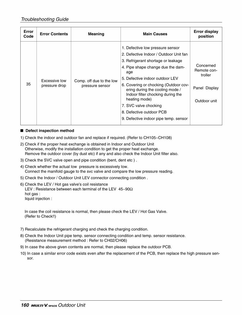
Troubleshooting Guide
160 Outdoor Unit
Excessive lowpressure drop
ErrorCode
Error Contents Meaning Main CausesError display
position
35Comp. off due to the low
pressure sensor
ConcernedRemote con-
troller
Panel Display
Outdoor unit
1. Defective low pressure sensor
2. Defective Indoor / Outdoor Unit fan
3. Refrigerant shortage or leakage
4. Pipe shape change due the dam-age
5. Defective indoor outdoor LEV
6. Covering or chocking (Outdoor cov-ering during the cooling mode /Indoor filter chocking during theheating mode)
7. SVC valve chocking
8. Defective outdoor PCB
9. Defective indoor pipe temp. sensor
Defect inspection method
1) Check the indoor and outdoor fan and replace if required. (Refer to CH105~CH108)
2) Check if the proper heat exchange is obtained in Indoor and Outdoor UnitOtherwise, modify the installation condition to get the proper heat exchange.Remove the outdoor cover (by dust etc) if any and also check the Indoor Unit filter also.
3) Check the SVC valve open and pipe condition (bent, dent etc ) .
4) Check whether the actual low pressure is excessively low.Connect the manifold gauge to the svc valve and compare the low pressure reading.
5) Check the Indoor / Outdoor Unit LEV connector connecting condition .
6) Check the LEV / Hot gas valve's coil resistanceLEV : Resistance between each terminal of the LEV 45~90Ωhot gas :liquid injection :
In case the coil resistance is normal, then please check the LEV / Hot Gas Valve.(Refer to Check!!)
7) Recalculate the refrigerant charging and check the charging condition.
8) Check the Indoor Unit pipe temp. sensor connecting condition and temp. sensor resistance.(Resistance measurement method : Refer to CH02/CH06)
9) In case the above given contents are normal, then please replace the outdoor PCB.
10) In case a similar error code exists even after the replacement of the PCB, then replace the high pressure sen-sor.

Service Manual 161
Troubleshooting Guide
Comp. dischargepipe temp. sensor
error
ErrorCode
Error Contents Meaning Main CausesError display
position
41Sensor measurement
value is abnormal (Open /Short)
ConcernedRemote con-
troller
Panel Display
Outdoor unit
1. Defective connection of the comp.discharge pipe temp. sensor
2. Defective discharge pipe temp.sensor of the comp (Open/Short)
3. Defective outdoor PCB
Defect inspection method
1) Check the comp. discharge pipe temp. sensor and the lead wire connecting condition.
2) Check whether the sensor resistance value is normal ? Otherwise, replace the sensor.
- Comp. discharge pipe temp. sensor : 10°C = 362kΩ, 25°C = 200kΩ, 50°C = 82kΩ, 100°C = 18.5kΩ3) In case the sensor connecting condition and the resistance value are normal, then please replace the outdoor
PCB.
4) If "n1" is displayed at the 7 segment, check comp AIf "n2" is displayed at the 7 segment, check comp B

Troubleshooting Guide
162 Outdoor Unit
Check discharge temp sensor of inverter compressor
Check discharge temp sensor of constant compressor

Service Manual 163
Troubleshooting Guide
Low pressure sen-sor error
ErrorCode
Error Contents Meaning Main CausesError display
position
42Sensor measured value is
not normal(Open / Short)
ConcernedRemote con-
troller
Panel Display
Outdoor unit
1. Defective low pressure sensor con-nector
2. Defective low pressure sensor(Open/Short)
3. Defective outdoor PCB
High pressuresensor error
ErrorCode
Error Contents Meaning Main CausesError display
position
43Sensor measured value isnot normal (Open/Short)
ConcernedRemote con-
troller
Panel Display
Outdoor unit
1. Defective high pressure sensorconnector
2. Defective high pressure sensorerror (Open/Short)
3. Outdoor PCB defect
Defect inspection method
1) Check the pressure sensor connecting condition and lead wire connecting condition.
2) In case the above condition is normal then replace the outdoor PCB .
3) If the error code persists even after the replacement of PCB then replace the concerned pressure sensor

Troubleshooting Guide
164 Outdoor Unit
Pressure sensor connector
High pressure sensor Low pressure sensor
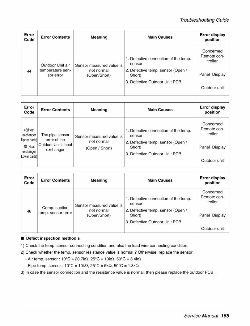
Service Manual 165
Troubleshooting Guide
Outdoor Unit airtemperature sen-
sor error
ErrorCode
Error Contents Meaning Main CausesError display
position
44Sensor measured value is
not normal(Open/Short)
ConcernedRemote con-
troller
Panel Display
Outdoor unit
1. Defective connection of the temp.sensor
2. Defective temp. sensor (Open /Short)
3. Defective Outdoor Unit PCB
The pipe sensorerror of the
Outdoor Unit’s heatexchanger
ErrorCode
Error Contents Meaning Main CausesError display
position
45(Heatexchanger
Upper parts)
48 (Heatexchanger
Lower parts)
Sensor measured value isnot normal
(Open / Short)
ConcernedRemote con-
troller
Panel Display
Outdoor unit
1. Defective connection of the temp.sensor
2. Defective temp. sensor (Open /Short)
3. Defective Outdoor Unit PCB
Comp. suctiontemp. sensor error
ErrorCode
Error Contents Meaning Main CausesError display
position
46Sensor measured value is
not normal(Open/Short)
ConcernedRemote con-
troller
Panel Display
Outdoor unit
1. Defective connection of the temp.sensor
2. Defective temp. sensor (Open /Short)
3. Defective Outdoor Unit PCB
Defect inspection method s
1) Check the temp. sensor connecting condition and also the lead wire connecting condition.
2) Check whether the temp. sensor resistance value is normal ? Otherwise, replace the sensor.
- Air temp. sensor : 10°C = 20.7kΩ, 25°C = 10kΩ, 50°C = 3.4kΩ- Pipe temp. sensor : 10°C = 10kΩ, 25°C = 5kΩ, 50°C = 1.8kΩ
3) In case the sensor connection and the resistance value is normal, then please replace the outdoor PCB .
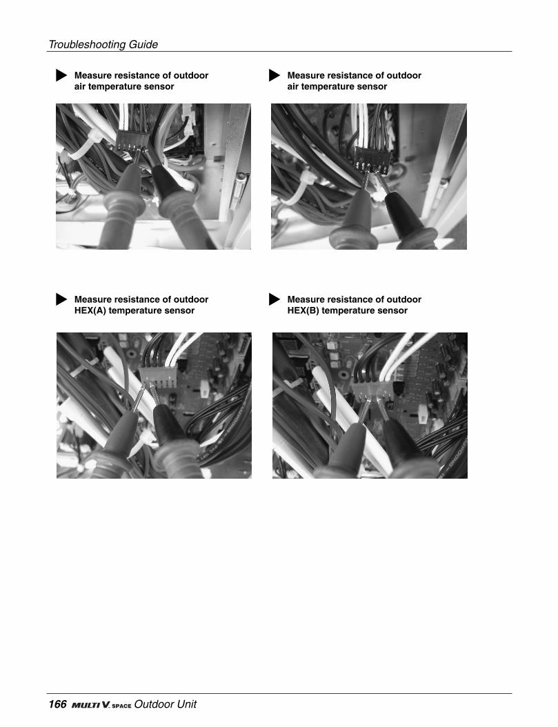
Troubleshooting Guide
166 Outdoor Unit
Measure resistance of outdoor air temperature sensor
Measure resistance of outdoor air temperature sensor
Measure resistance of outdoor HEX(A) temperature sensor
Measure resistance of outdoor HEX(B) temperature sensor
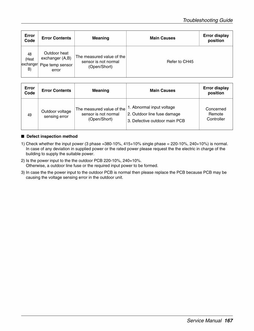
Service Manual 167
Troubleshooting Guide
Outdoor heatexchanger (A,B)
Pipe temp sensorerror
ErrorCode
Error Contents Meaning Main CausesError display
position
48(Heat
exchangerB)
The measured value of thesensor is not normal
(Open/Short)Refer to CH45
Outdoor voltagesensing error
ErrorCode
Error Contents Meaning Main CausesError display
position
49The measured value of the
sensor is not normal(Open/Short)
ConcernedRemote
Controller
1. Abnormal input voltage
2. Outdoor line fuse damage
3. Defective outdoor main PCB
Defect inspection method
1) Check whether the input power (3 phase =380-10%, 415+10% single phase = 220-10%, 240+10%) is normal.In case of any deviation in supplied power or the rated power please request the the electric in charge of thebuilding to supply the suitable power.
2) Is the power input to the the outdoor PCB 220-10%, 240+10%.Otherwise, a outdoor line fuse or the required input power to be formed.
3) In case the the power input to the outdoor PCB is normal then please replace the PCB because PCB may becausing the voltage sensing error in the outdoor unit.

Troubleshooting Guide
168 Outdoor Unit
Measure input power of outdoor unit
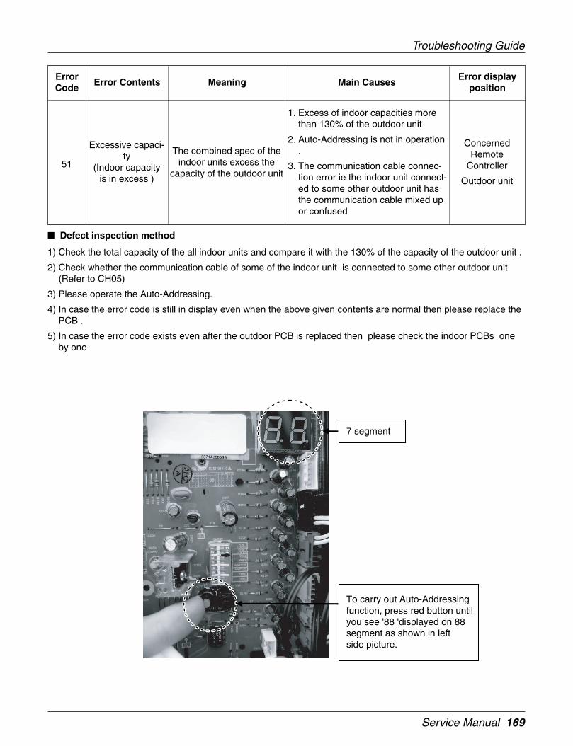
Service Manual 169
Troubleshooting Guide
Excessive capaci-ty
(Indoor capacityis in excess )
ErrorCode
Error Contents Meaning Main CausesError display
position
51The combined spec of the
indoor units excess thecapacity of the outdoor unit
ConcernedRemote
Controller
Outdoor unit
1. Excess of indoor capacities morethan 130% of the outdoor unit
2. Auto-Addressing is not in operation.
3. The communication cable connec-tion error ie the indoor unit connect-ed to some other outdoor unit hasthe communication cable mixed upor confused
Defect inspection method
1) Check the total capacity of the all indoor units and compare it with the 130% of the capacity of the outdoor unit .
2) Check whether the communication cable of some of the indoor unit is connected to some other outdoor unit(Refer to CH05)
3) Please operate the Auto-Addressing.
4) In case the error code is still in display even when the above given contents are normal then please replace thePCB .
5) In case the error code exists even after the outdoor PCB is replaced then please check the indoor PCBs oneby one
To carry out Auto-Addressing function, press red button until you see '88 'displayed on 88 segment as shown in left side picture.
7 segment
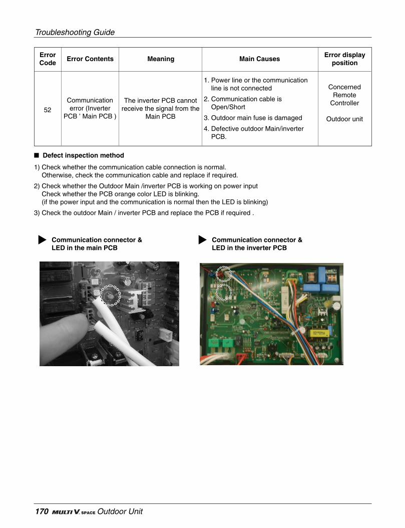
Troubleshooting Guide
170 Outdoor Unit
Communicationerror (Inverter
PCB ’ Main PCB )
ErrorCode
Error Contents Meaning Main CausesError display
position
52The inverter PCB cannot
receive the signal from theMain PCB
ConcernedRemote
Controller
Outdoor unit
1. Power line or the communicationline is not connected
2. Communication cable isOpen/Short
3. Outdoor main fuse is damaged
4. Defective outdoor Main/inverterPCB.
Defect inspection method
1) Check whether the communication cable connection is normal.Otherwise, check the communication cable and replace if required.
2) Check whether the Outdoor Main /inverter PCB is working on power inputCheck whether the PCB orange color LED is blinking.(if the power input and the communication is normal then the LED is blinking)
3) Check the outdoor Main / inverter PCB and replace the PCB if required .
Communication connector & LED in the main PCB
Communication connector & LED in the inverter PCB
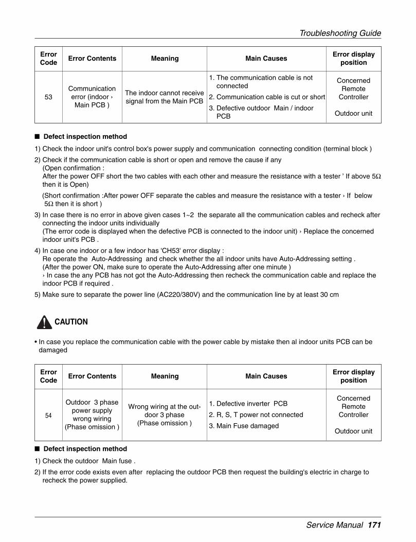
Service Manual 171
Troubleshooting Guide
Communicationerror (indoor ›Main PCB )
ErrorCode
Error Contents Meaning Main CausesError display
position
53The indoor cannot receivesignal from the Main PCB
ConcernedRemote
Controller
Outdoor unit
1. The communication cable is notconnected
2. Communication cable is cut or short
3. Defective outdoor Main / indoorPCB
Defect inspection method
1) Check the indoor unit's control box's power supply and communication connecting condition (terminal block )
2) Check if the communication cable is short or open and remove the cause if any(Open confirmation :After the power OFF short the two cables with each other and measure the resistance with a tester ’ If above 5Ωthen it is Open)
(Short confirmation :After power OFF separate the cables and measure the resistance with a tester › If below5Ω then it is short )
3) In case there is no error in above given cases 1~2 the separate all the communication cables and recheck afterconnecting the indoor units individually(The error code is displayed when the defective PCB is connected to the indoor unit) › Replace the concernedindoor unit's PCB .
4) In case one indoor or a few indoor has 'CH53' error display :Re operate the Auto-Addressing and check whether the all indoor units have Auto-Addressing setting .(After the power ON, make sure to operate the Auto-Addressing after one minute )› In case the any PCB has not got the Auto-Addressing then recheck the communication cable and replace theindoor PCB if required .
5) Make sure to separate the power line (AC220/380V) and the communication line by at least 30 cm
CAUTION
• In case you replace the communication cable with the power cable by mistake then al indoor units PCB can bedamaged
Outdoor 3 phasepower supplywrong wiring
(Phase omission )
ErrorCode
Error Contents Meaning Main CausesError display
position
54Wrong wiring at the out-
door 3 phase(Phase omission )
ConcernedRemote
Controller
Outdoor unit
1. Defective inverter PCB
2. R, S, T power not connected
3. Main Fuse damaged
Defect inspection method
1) Check the outdoor Main fuse .
2) If the error code exists even after replacing the outdoor PCB then request the building's electric in charge torecheck the power supplied.
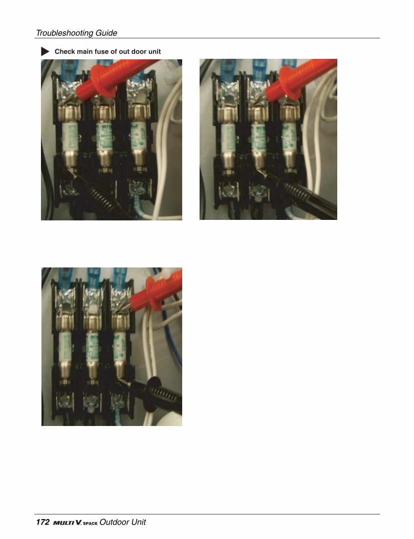
Troubleshooting Guide
172 Outdoor Unit
Check main fuse of out door unit

Service Manual 173
Troubleshooting Guide
Communicationerror
(Main PCB ’inverter PCB )
ErrorCode
Error Contents Meaning Main CausesError display
position
57Main PCB cannot receivethe signal from the inverter
PCBRefer to CH52
Excess of heat ininverter PCB heat
sink
ErrorCode
Error Contents Meaning Main CausesError display
position
62Excessive rise of
Inverter heat sink tempera-ture
ConcernedRemote
Controller
Outdoor unit
1. Defective heat sink fan
2. Overheat of the inverter comp IPM
3. Inverter fan IPM overheat
4. Defective fan Main PCB
5. Defective heat sink region connec-tion
6. Defective heat sink fan power sup-ply terminal
Defect inspection method
1) Check whether the heat sink cooling fan is normal ?Check the power supply connector to the cooling fan of the heat sink on the upper side of the Main PCB is12Vdc (Always operating when the inverter comp is operating)Also check the heat sink cooling fan Lead-Wire
2) Check whether the air is coming out from the cooling fan of the heat sink on the upper side of the of the controlbox.Check the assembly condition in the surrounding of the heat sink
6) In case the above given 4,5, the fan is not working then replace the cooling fan.
7) Check the compressor IPM and replace of required.(refer: error code 21)
8) Check if the fan IPM is normal. Otherwise, replace the IPM .
9) In case the error persists even after the fan IPM is replaced then replace the fan main PCB .
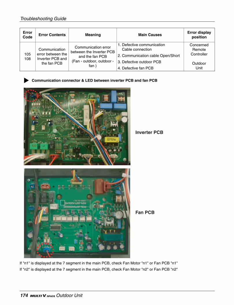
Troubleshooting Guide
174 Outdoor Unit
If "n1" is displayed at the 7 segment in the main PCB, check Fan Motor "n1" or Fan PCB "n1"
If "n2" is displayed at the 7 segment in the main PCB, check Fan Motor "n2" or Fan PCB "n2"
Communicationerror between theInverter PCB and
the fan PCB
ErrorCode
Error Contents Meaning Main CausesError display
position
105108
Communication errorbetween the Inverter PCB
and the fan PCB(Fan › outdoor, outdoor ›
fan )
ConcernedRemote
Controller
OutdoorUnit
1. Defective communicationCable connection
2. Communication cable Open/Short
3. Defective outdoor PCB
4. Defective fan PCB
Communication connector & LED between inverter PCB and fan PCB
Inverter PCB
Fan PCB
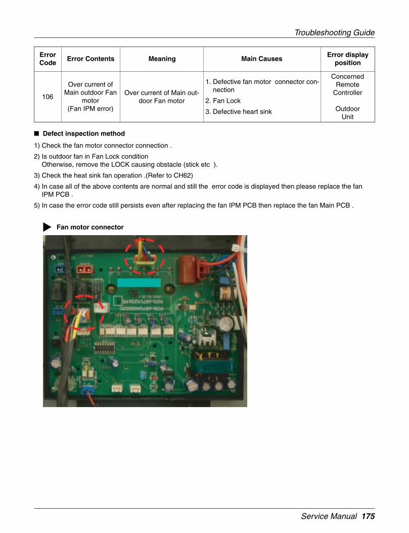
Service Manual 175
Troubleshooting Guide
Over current ofMain outdoor Fan
motor(Fan IPM error)
ErrorCode
Error Contents Meaning Main CausesError display
position
106Over current of Main out-
door Fan motor
ConcernedRemote
Controller
OutdoorUnit
1. Defective fan motor connector con-nection
2. Fan Lock
3. Defective heart sink
Defect inspection method
1) Check the fan motor connector connection .
2) Is outdoor fan in Fan Lock conditionOtherwise, remove the LOCK causing obstacle (stick etc ).
3) Check the heat sink fan operation .(Refer to CH62)
4) In case all of the above contents are normal and still the error code is displayed then please replace the fanIPM PCB .
5) In case the error code still persists even after replacing the fan IPM PCB then replace the fan Main PCB .
Fan motor connector

Troubleshooting Guide
176 Outdoor Unit
Fan IPM

Service Manual 177
Troubleshooting Guide
Low voltage in thefan motor
ErrorCode
Error Contents Meaning Main CausesError display
position
107Low voltage in the fan
motor
ConcernedRemote
Controller
OutdoorUnit
1. Defective fan PCB DC link voltagelead wire connection
2. Abnormal fan PCB Capacitor
3. Abnormal fan PCB input power
4. Fan PCB defect
Defect inspection method
1) Check the fan PCB DC link voltage lead wire connecting condition .
2) Check Fan PCB input power voltage (normal : rated ± 10%)
3) Check whether the fan PCB Capacitor ahs any abnormality.In case it is abnormal then outer shape is deformed (outer shape expansion).
4) In case of Capacitor abnormality replace the fan PCB .
5) In case the error code exists even after the PCB replacement then replace the fan IPM PCB
DC link location of outdoor fan
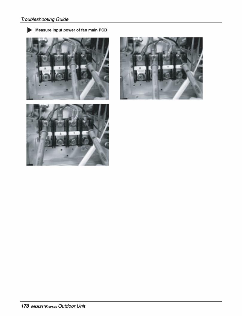
Troubleshooting Guide
178 Outdoor Unit
Measure input power of fan main PCB
Service Manual 179
Troubleshooting Guide
Sensor error atthe outdoor LiquidRefrigerant pipe
ErrorCode
Error Contents Meaning Main CausesError display
position
113Abnormal value of Sensor
measurement(Open/Short)
ConcernedRemote
Controller
Outdoor unit
1. Defective temp sensor connectorconnection
2. Defective temp sensor Open/Short)
3. Defective outdoor PCB
Sensor error atthe outdoor subcooling inlet or
outlet
ErrorCode
Error Contents Meaning Main CausesError display
position
114(MainSub cool
inlet)
115(MainSub cooloutlet)
Abnormal value of the sen-sor measurement
(Open/Short)
ConcernedRemote
Controller
Outdoor unit
1. Defective temp sensor connectorconnection
2. Defective temp sensor(Open/Short)
3. Defective outdoor PCB
Defect inspection method
1) Check the temp sensor connector connecting condition and lead wire.
2) Is the temp sensor resistance value normal? Otherwise, replace the sensor- Pipe temp sensor : 10°C = 10kΩ : 25°C = 5kΩ : 50°C = 1.8kΩ
3) In case the sensor connection and the resistance value is correct then replace the outdoor PCB .
Communicationerror between theMain PCB and the
fan PCB
ErrorCode
Error Contents Meaning Main CausesError display
position
108
Communication errorbetween the Main PCB
and the fan PCB(Fan › outdoor , outdoor ›
fan )
Refer to CH105

Troubleshooting Guide
180 Outdoor Unit
Sub-cool circuit in the outdoor unit
Measure resistance of LEV coil
Measure temp sensor of liquid pipe
Measure temp sensor of sub-cool outlet
Measure temp sensor of sub-cool inlet

Service Manual 181
Troubleshooting Guide
Outdoor 4way(reversing valve)Switching Error
ErrorCode
Error Contents Meaning Main CausesError display
position
151When the Main or the Suboutdoor has one of themhaving a 4way valve error
ConcernedRemote
Controller
Outdoor unit
1. 4 way valve error due to the inlet ofsludge into the valve
2. Comp damage leading to pressurechange does not occur ,
3. Wrong installation of common pipebetween the outdoor units
4. 4way valve error
Defect inspection method
1) Check whether the piping between the outdoor units is normal(liquid pipe should be connected to liquid pipe, common pipe be connected to common pipe ) fi Pipe modifica-tion
2) Check whether the Main/Sub outdoor compressor is damaged or not.(Refer to CH21)
3) Please confirm the Main PCB's 4way valve terminal voltage (220V±10%).In case of abnormal voltage please replace the outdoor main PCB
4) Check the outdoor PCB's 4way valve connector connections and coil connections.
5) Measure the 4way valve's coil resistance at the connectorNormal resistance :
6) In case the error still persists even after the all above conditions are normal then replace the 4way valve .

Troubleshooting Guide
182 Outdoor Unit
4way valve in the outdoor unit
4way valve connector on the Main PCB
Service Manual 183
Exploded View &Replacement Parts List

184 Indoor Unit
Explodede View & Replacement Parts List
7. Exploded View & Replacement Parts List
352118 55211G
330870
268714
268713
249951
135511
263230-1
263230-2
263230-3
158580
266012
158591
55211G
354211
TE (Standard model)

Service Manual 185
Explodede View & Replacement Parts List
352118 55211G
330870
268714
268713
249951
135511
263230-1
263230-2
263230-3
158580
266012
158591
55211G
354211
266090
159830
TE (Plasma model)

186 Indoor Unit
Explodede View & Replacement Parts List
130412
152510-2
140570
130911-1
130911-2
130911-3
152510-1
W1BZZ
359012
346810
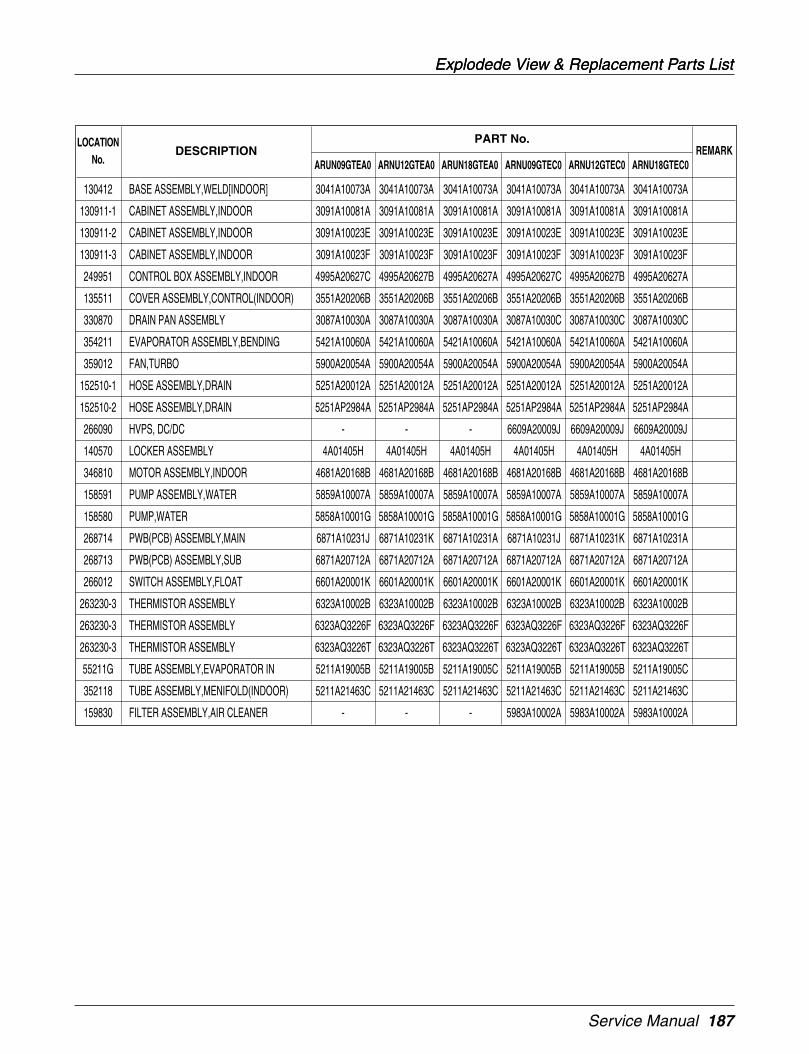
Service Manual 187
Explodede View & Replacement Parts ListExplodede View & Replacement Parts List
PART No.
130412 BASE ASSEMBLY,WELD[INDOOR] 3041A10073A 3041A10073A 3041A10073A 3041A10073A 3041A10073A 3041A10073A
130911-1 CABINET ASSEMBLY,INDOOR 3091A10081A 3091A10081A 3091A10081A 3091A10081A 3091A10081A 3091A10081A
130911-2 CABINET ASSEMBLY,INDOOR 3091A10023E 3091A10023E 3091A10023E 3091A10023E 3091A10023E 3091A10023E
130911-3 CABINET ASSEMBLY,INDOOR 3091A10023F 3091A10023F 3091A10023F 3091A10023F 3091A10023F 3091A10023F
249951 CONTROL BOX ASSEMBLY,INDOOR 4995A20627C 4995A20627B 4995A20627A 4995A20627C 4995A20627B 4995A20627A
135511 COVER ASSEMBLY,CONTROL(INDOOR) 3551A20206B 3551A20206B 3551A20206B 3551A20206B 3551A20206B 3551A20206B
330870 DRAIN PAN ASSEMBLY 3087A10030A 3087A10030A 3087A10030A 3087A10030C 3087A10030C 3087A10030C
354211 EVAPORATOR ASSEMBLY,BENDING 5421A10060A 5421A10060A 5421A10060A 5421A10060A 5421A10060A 5421A10060A
359012 FAN,TURBO 5900A20054A 5900A20054A 5900A20054A 5900A20054A 5900A20054A 5900A20054A
152510-1 HOSE ASSEMBLY,DRAIN 5251A20012A 5251A20012A 5251A20012A 5251A20012A 5251A20012A 5251A20012A
152510-2 HOSE ASSEMBLY,DRAIN 5251AP2984A 5251AP2984A 5251AP2984A 5251AP2984A 5251AP2984A 5251AP2984A
266090 HVPS, DC/DC - - - 6609A20009J 6609A20009J 6609A20009J
140570 LOCKER ASSEMBLY 4A01405H 4A01405H 4A01405H 4A01405H 4A01405H 4A01405H
346810 MOTOR ASSEMBLY,INDOOR 4681A20168B 4681A20168B 4681A20168B 4681A20168B 4681A20168B 4681A20168B
158591 PUMP ASSEMBLY,WATER 5859A10007A 5859A10007A 5859A10007A 5859A10007A 5859A10007A 5859A10007A
158580 PUMP,WATER 5858A10001G 5858A10001G 5858A10001G 5858A10001G 5858A10001G 5858A10001G
268714 PWB(PCB) ASSEMBLY,MAIN 6871A10231J 6871A10231K 6871A10231A 6871A10231J 6871A10231K 6871A10231A
268713 PWB(PCB) ASSEMBLY,SUB 6871A20712A 6871A20712A 6871A20712A 6871A20712A 6871A20712A 6871A20712A
266012 SWITCH ASSEMBLY,FLOAT 6601A20001K 6601A20001K 6601A20001K 6601A20001K 6601A20001K 6601A20001K
263230-3 THERMISTOR ASSEMBLY 6323A10002B 6323A10002B 6323A10002B 6323A10002B 6323A10002B 6323A10002B
263230-3 THERMISTOR ASSEMBLY 6323AQ3226F 6323AQ3226F 6323AQ3226F 6323AQ3226F 6323AQ3226F 6323AQ3226F
263230-3 THERMISTOR ASSEMBLY 6323AQ3226T 6323AQ3226T 6323AQ3226T 6323AQ3226T 6323AQ3226T 6323AQ3226T
55211G TUBE ASSEMBLY,EVAPORATOR IN 5211A19005B 5211A19005B 5211A19005C 5211A19005B 5211A19005B 5211A19005C
352118 TUBE ASSEMBLY,MENIFOLD(INDOOR) 5211A21463C 5211A21463C 5211A21463C 5211A21463C 5211A21463C 5211A21463C
159830 FILTER ASSEMBLY,AIR CLEANER - - - 5983A10002A 5983A10002A 5983A10002A
LOCATIONNo.
DESCRIPTION REMARKARUN09GTEA0 ARNU12GTEA0 ARUN18GTEA0 ARNU09GTEC0 ARNU12GTEC0 ARNU18GTEC0
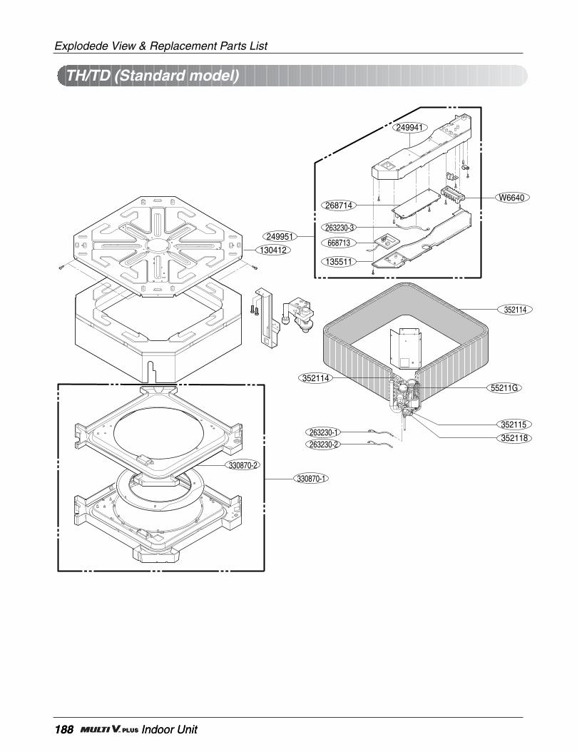
188 Indoor Unit
Explodede View & Replacement Parts List
188 Indoor Unit
130412
352114
263230-2352118
352115
249941
263230-1
352114
268714
249951
135511
668713
263230-3
W6640
55211G
330870-2
330870-1
TH/TD (Standard model)

Service Manual 189
Explodede View & Replacement Parts List
130412
352114
263230-2352118
352115
249941
159830
266090
263230-1
352114
268714
249951
135511
668713
249941
263230-3
W6640
55211G
330870-2
330870-1
TH/TD (Plasma model)

190 Indoor Unit
Explodede View & Replacement Parts List
190 Indoor Unit
130412
346810
152510-2
359012
130911-4
130911-3
152510-1
140570
W0CZZ
THTD
130911-4
130911-2
W1BZZ
349600
W6851130911-1
349600

Service Manual 191
Explodede View & Replacement Parts List
PART No.
130412 BASE ASSEMBLY,WELD[INDOOR] 3041A10069A 3041A10069A 3041A10069A 3041A10069A
W1BZZ BOLT,DRAWING 3A00255D 3A00255D 3A00255D 3A00255D
130911-1 CABINET ASSEMBLY,INDOOR 3091A10077A 3091A10077A 3091A10077A 3091A10077A
130911-2 CABINET ASSEMBLY,INDOOR 3091A10075A 3091A10075A 3091A10075A 3091A10075A
130911-3 CABINET ASSEMBLY,INDOOR 3091A10075B 3091A10075B 3091A10075B 3091A10075B
130911-4 CABINET ASSEMBLY,INDOOR 3091A10085A 3091A10085A 3091A10085A 3091A10085A
249951 CONTROL BOX ASSEMBLY,INDOOR 4995A10203B 4995A10203C 4995A10203B 4995A10203C
135511 COVER ASSEMBLY,CONTROL(INDOOR) 3551A20206A 3551A20206A 3551A20206A 3551A20206A
330870-1 DRAIN PAN ASSEMBLY 3087A10035E 3087A10035E 3087A10035D 3087A10035D
330870-2 DRAIN PAN ASSEMBLY 3087A10029A 3087A10029A 3087A10029A 3087A10029A
354211 EVAPORATOR ASSEMBLY,BENDING 5421A10061A 5421A10061A 5421A10061A 5421A10061A
359012 FAN,TURBO 5900A10016A 5900A10016A 5900A10016A 5900A10016A
152510-1 HOSE ASSEMBLY,DRAIN 5251A10003A 5251A10003A 5251A10003A 5251A10003A
152510-2 HOSE ASSEMBLY,DRAIN 5251AP2984C 5251AP2984C 5251AP2984C 5251AP2984C
266090 HVPS, DC/DC - - 6609A20009L 6609A20009L
140570 LOCKER ASSEMBLY 4A01405C 4A01405C 4A01405C 4A01405C
346810 MOTOR ASSEMBLY,INDOOR 4681A20168A 4681A20168A 4681A20168A 4681A20168A
349480 ORIFICE 4948A20039A 4948A20039A 4948A20039A 4948A20039A
158591 PUMP ASSEMBLY,WATER 5859A10006C 5859A10006C 5859A10006C 5859A10006C
158580 PUMP,WATER 5858A10001F 5858A10001F 5858A10001F 5858A10001F
268714 PWB(PCB) ASSEMBLY,MAIN 6871A10231C 6871A10231D 6871A10231C 6871A10231D
268713 PWB(PCB) ASSEMBLY,SUB 6871A20712A 6871A20712A 6871A20712A 6871A20712A
266012 SWITCH ASSEMBLY,FLOAT 6601A20001K 6601A20001K 6601A20001K 6601A20001K
263230-1 THERMISTOR ASSEMBLY 6323A30002A 6323A30002A 6323A30002A 6323A30002A
263230-2 THERMISTOR ASSEMBLY 6323AQ3226W 6323AQ3226W 6323AQ3226W 6323AQ3226W
263230-3 THERMISTOR ASSEMBLY 6323A10002B 6323A10002B 6323A10002B 6323A10002B
55211G TUBE ASSEMBLY,EXPANSION 5211A10298F 5211A10298E 5211A10298F 5211A10298E
352118 TUBE ASSEMBLY,MENIFOLD(INDOOR) 5211A10600F 5211A10600F 5211A10600F 5211A10600F
LOCATIONNo.
DESCRIPTION REMARKARNU24GTHA0 ARNU28GTHA0 ARNU24GTHC0 ARNU28GTHC0
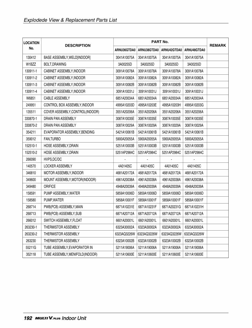
192 Indoor Unit
Explodede View & Replacement Parts List
192 Indoor Unit
PART No.
130412 BASE ASSEMBLY,WELD[INDOOR] 3041A10075A 3041A10075A 3041A10075A 3041A10075A
W1BZZ BOLT,DRAWING 3A00255D 3A00255D 3A00255D 3A00255D
130911-1 CABINET ASSEMBLY,INDOOR 3091A10078A 3091A10078A 3091A10078A 3091A10078A
130911-2 CABINET ASSEMBLY,INDOOR 3091A10082A 3091A10082A 3091A10082A 3091A10082A
130911-3 CABINET ASSEMBLY,INDOOR 3091A10082B 3091A10082B 3091A10082B 3091A10082B
130911-4 CABINET ASSEMBLY,INDOOR 3091A10031J 3091A10031J 3091A10031J 3091A10031J
W6851 CABLE ASSEMBLY 6851A20034A 6851A20034A 6851A20034A 6851A20034A
249951 CONTROL BOX ASSEMBLY,INDOOR 4995A10203D 4995A10203E 4995A10203H 4995A10203G
135511 COVER ASSEMBLY,CONTROL(INDOOR) 3551A20206A 3551A20206A 3551A20206A 3551A20206A
330870-1 DRAIN PAN ASSEMBLY 3087A10035E 3087A10035E 3087A10035E 3087A10035E
330870-2 DRAIN PAN ASSEMBLY 3087A10029A 3087A10029A 3087A10029A 3087A10029A
354211 EVAPORATOR ASSEMBLY,BENDING 5421A10061B 5421A10061B 5421A10061B 5421A10061B
359012 FAN,TURBO 5900A20055A 5900A20055A 5900A20055A 5900A20055A
152510-1 HOSE ASSEMBLY,DRAIN 5251A10003B 5251A10003B 5251A10003B 5251A10003B
152510-2 HOSE ASSEMBLY,DRAIN 5251AP2984C 5251AP2984C 5251AP2984C 5251AP2984C
266090 HVPS,DC/DC - - - -
140570 LOCKER ASSEMBLY 4A01405C 4A01405C 4A01405C 4A01405C
346810 MOTOR ASSEMBLY,INDOOR 4681A20172A 4681A20172A 4681A20172A 4681A20172A
349600 MOUNT ASSEMBLY,MOTOR(INDOOR) 4961A20038A 4961A20038A 4961A20038A 4961A20038A
349480 ORIFICE 4948A20039A 4948A20039A 4948A20039A 4948A20039A
158591 PUMP ASSEMBLY,WATER 5859A10006D 5859A10006D 5859A10006D 5859A10006D
158580 PUMP,WATER 5858A10001F 5858A10001F 5858A10001F 5858A10001F
268714 PWB(PCB) ASSEMBLY,MAIN 6871A10231E 6871A10231F 6871A20231G 6871A10231H
268713 PWB(PCB) ASSEMBLY,SUB 6871A20712A 6871A20712A 6871A20712A 6871A20712A
266012 SWITCH ASSEMBLY,FLOAT 6601A20001L 6601A20001L 6601A20001L 6601A20001L
263230-1 THERMISTOR ASSEMBLY 6323A30002A 6323A30002A 6323A30002A 6323A30002A
263230-2 THERMISTOR ASSEMBLY 6323AQ3226W 6323AQ3226W 6323AQ3226W 6323AQ3226W
263230 THERMISTOR ASSEMBLY 6323A10002B 6323A10002B 6323A10002B 6323A10002B
55211G TUBE ASSEMBLY,EVAPORATOR IN 5211A19006A 5211A19006A 5211A19006A 5211A19006A
352118 TUBE ASSEMBLY,MENIFOLD(INDOOR) 5211A10600E 5211A10600E 5211A10600E 5211A10600E
LOCATIONNo.
DESCRIPTION REMARKARNU36GTDA0 ARNU38GTDA0 ARNU42GTDA0 ARNU48GTDA0

Service Manual 193
Explodede View & Replacement Parts List
PART No.
130412 BASE ASSEMBLY,WELD[INDOOR] 3041A10075A 3041A10075A 3041A10075A 3041A10075A
W1BZZ BOLT,DRAWING 3A00255D 3A00255D 3A00255D 3A00255D
130911-1 CABINET ASSEMBLY,INDOOR 3091A10078A 3091A10078A 3091A10078A 3091A10078A
130911-2 CABINET ASSEMBLY,INDOOR 3091A10082A 3091A10082A 3091A10082A 3091A10082A
130911-3 CABINET ASSEMBLY,INDOOR 3091A10082B 3091A10082B 3091A10082B 3091A10082B
130911-4 CABINET ASSEMBLY,INDOOR 3091A10031J 3091A10031J 3091A10031J 3091A10031J
W6851 CABLE ASSEMBLY 6851A20034A 6851A20034A 6851A20034A 6851A20034A
249951 CONTROL BOX ASSEMBLY,INDOOR 4995A10203D 4995A10203E 4995A10203H 4995A10203G
135511 COVER ASSEMBLY,CONTROL(INDOOR) 3551A20206A 3551A20206A 3551A20206A 3551A20206A
330870-1 DRAIN PAN ASSEMBLY 3087A10035D 3087A10035D 3087A10035D 3087A10035D
330870-2 DRAIN PAN ASSEMBLY 3087A10029A 3087A10029A 3087A10029A 3087A10029A
354211 EVAPORATOR ASSEMBLY,BENDING 5421A10061B 5421A10061B 5421A10061B 5421A10061B
359012 FAN,TURBO 5900A20055A 5900A20055A 5900A20055A 5900A20055A
152510-1 HOSE ASSEMBLY,DRAIN 5251A10003B 5251A10003B 5251A10003B 5251A10003B
152510-2 HOSE ASSEMBLY,DRAIN 5251AP2984C 5251AP2984C 5251AP2984C 5251AP2984C
266090 HVPS,DC/DC 6609A20009L 6609A20009L 6609A20009L 6609A20009L
140570 LOCKER ASSEMBLY 4A01405C 4A01405C 4A01405C 4A01405C
346810 MOTOR ASSEMBLY,INDOOR 4681A20172A 4681A20172A 4681A20172A 4681A20172A
349600 MOUNT ASSEMBLY,MOTOR(INDOOR) 4961A20038A 4961A20038A 4961A20038A 4961A20038A
349480 ORIFICE 4948A20039A 4948A20039A 4948A20039A 4948A20039A
158591 PUMP ASSEMBLY,WATER 5859A10006D 5859A10006D 5859A10006D 5859A10006D
158580 PUMP,WATER 5858A10001F 5858A10001F 5858A10001F 5858A10001F
268714 PWB(PCB) ASSEMBLY,MAIN 6871A10231E 6871A10231F 6871A20231G 6871A10231H
268713 PWB(PCB) ASSEMBLY,SUB 6871A20712A 6871A20712A 6871A20712A 6871A20712A
266012 SWITCH ASSEMBLY,FLOAT 6601A20001L 6601A20001L 6601A20001L 6601A20001L
263230-1 THERMISTOR ASSEMBLY 6323A30002A 6323A30002A 6323A30002A 6323A30002A
263230-2 THERMISTOR ASSEMBLY 6323AQ3226W 6323AQ3226W 6323AQ3226W 6323AQ3226W
263230 THERMISTOR ASSEMBLY 6323A10002B 6323A10002B 6323A10002B 6323A10002B
55211G TUBE ASSEMBLY,EVAPORATOR IN 5211A19006A 5211A19006A 5211A19006A 5211A19006A
352118 TUBE ASSEMBLY,MENIFOLD(INDOOR) 5211A10600E 5211A10600E 5211A10600E 5211A10600E
LOCATIONNo.
DESCRIPTION REMARKARNU36GTDC0 ARNU38GTDC0 ARNU42GTDC0 ARNU48GTDC0
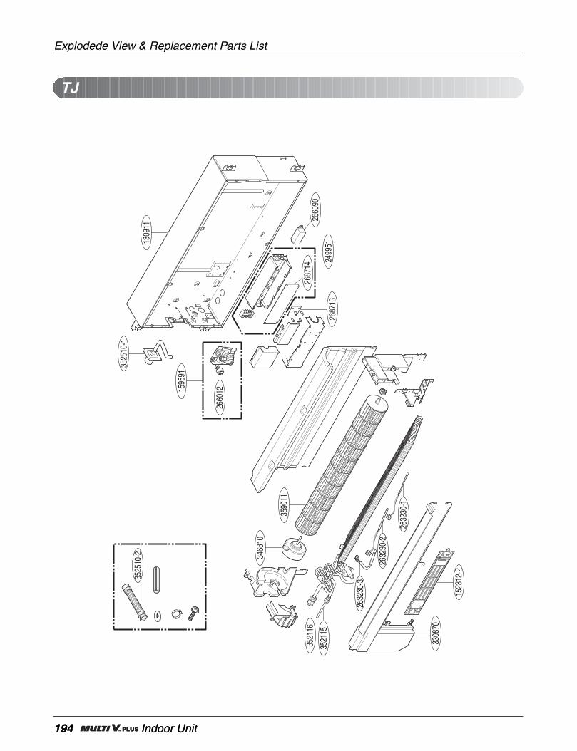
194 Indoor Unit
Explodede View & Replacement Parts List
194 Indoor Unit
TJ
3525
10-2
2632
30-2
2632
30-3
3521
16
3521
15
3308
70
3468
10
1523
12-2
2632
30-1
3590
11
3525
10-1
1595
91
1309
11
2687
13
2660
12
2499
51
2687
1426
6090
Service Manual 195
Explodede View & Replacement Parts List
PART No.
130911 CABINET ASSEMBLY,INDOOR 3091A10087B 3091A10087B 3091A10087B
158591 PUMP ASSEMBLY,WATER 5859A20005A 5859A20005A 5859A20005A
249951 CASE ASSEMBLY,CONTROL(INDOOR) 4995A29009C 4995A29009D 4995A29009A
263230-1 THERMISTOR,NTC 6323AQ3226E 6323AQ3226E 6323AQ3226E EVA-IN
263230-2 THERMISTOR,NTC 6323AQ3226V 6323AQ3226V 6323AQ3226V EVA-OUT
263230-3 THERMISTOR,NTC 6323A30004A 6323A30004A 6323A30004A AIR
266012 SWITCH ASSEMBLY 6601A20001K 6601A20001K 6601A20001K
268713 PCB ASSEMBLY,SUB 6871A20712A 6871A20712A 6871A20712A
268714 PCB ASSEMBLY,MAIN 6871A10231M 6871A10231N 6871A10231P
330870 PAN ASSEMBLY,DRAIN 3087A10033A 3087A10033A 3087A10033A
346810 MOTOR,UNCLASSIFIED 4681A20091K 4681A20091K 4681A20091K
352115 TUBE ASSEMBLY,EXPANSION 5211A29909A 5211A29909A 5211A29909A EVA-IN
352116 TUBE ASSEMBLY,MENIFOLD(INDOOR) 5211A29910A 5211A29910A 5211A29910A EVA-OUT
352150-2 HOSE ASSEMBLY,DRAIN 5251AP2984C 5251AP2984C 5251AP2984C
352510-1 HOSE ASSEMBLY,DRAIN 5251A20013A 5251A20013A 5251A20013A
359011 FAN ASSEMBLY,CROSS FLOW 5901AR2441A 5901AR2441A 5901AR2441A
LOCATIONNo.
DESCRIPTION REMARKARNU07GTJA0 ARNU09GTJA0 ARNU12GTJA0

196 Indoor Unit
Explodede View & Replacement Parts List
196 Indoor Unit
PART No.
130911 CABINET ASSEMBLY,INDOOR 3091A10087C 3091A10087C 3091A10087C
152312 FILTER ASSEMBLY,AIR CLEANER 5983A20017K 5983A20017K 5983A20017K
158591 PUMP ASSEMBLY,WATER 5859A20005A 5859A20005A 5859A20005A
249951 CASE ASSEMBLY,CONTROL(INDOOR) 4995A29009C 4995A29009D 4995A29009A
263230-1 THERMISTOR,NTC 6323AQ3226E 6323AQ3226E 6323AQ3226E EVA-IN
263230-2 THERMISTOR,NTC 6323AQ3226V 6323AQ3226V 6323AQ3226V EVA-OUT
263230-3 THERMISTOR,NTC 6323A30004A 6323A30004A 6323A30004A AIR
266012 SWITCH ASSEMBLY 6601A20001K 6601A20001K 6601A20001K
266090 HVPS,DC/DC 6609A20009P 6609A20009P 6609A20009P
268713 PCB ASSEMBLY,SUB 6871A20712A 6871A20712A 6871A20712A
268714 PCB ASSEMBLY,MAIN 6871A10231M 6871A10231N 6871A10231P
330870 PAN ASSEMBLY,DRAIN 3087A10033A 3087A10033A 3087A10033A
346810 MOTOR,UNCLASSIFIED 4681A20091K 4681A20091K 4681A20091K
352115 TUBE ASSEMBLY,EXPANSION 5211A29909A 5211A29909A 5211A29909A EVA-IN
352116 TUBE ASSEMBLY,MENIFOLD(INDOOR) 5211A29910A 5211A29910A 5211A29910A EVA-OUT
352150-2 HOSE ASSEMBLY,DRAIN 5251AP2984C 5251AP2984C 5251AP2984C
352510-1 HOSE ASSEMBLY,DRAIN 5251A20013A 5251A20013A 5251A20013A
359011 FAN ASSEMBLY,CROSS FLOW 5901AR2441A 5901AR2441A 5901AR2441A
LOCATIONNo.
DESCRIPTION REMARKARNU07GTJC0 ARNU09GTJC0 ARNU12GTJC0
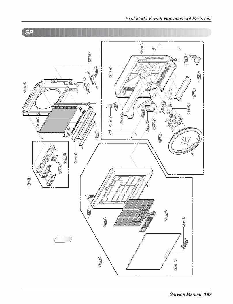
Service Manual 197
Explodede View & Replacement Parts List
SP13
5515
1355
00-3
2687
14-1
2687
14-2
1475
81
3590
12
3496
00
3523
80
1468
11
1468
11
1475
81
3468
10
1475
81
2687
12
1355
00-1
1314
10
3542
10
1355
00-214
6811
1523
02
2687
17
3308
70
1353
12
1353
14
1598
30
2499
51
3521
163521
15
2632
30-1
2632
30-2
3521
50
198 Indoor Unit
Explodede View & Replacement Parts List
198 Indoor Unit
ARNU07GSP*0 ARNU09GSP*0 ARNU12GSP*0
PART No.
131410 CHASSIS ASSEMBLY 3041A20030C 3041A20030C 3041A20030C135312 GRILLE ASSEMBLY, FRONT(INDOOR) METAL 3531A20029S 3531A20029S 3531A20029S135314 GRILLE ASSEMBLY, INLET BLUE 3531A20278B 3531A20278B 3531A20278B
METAL 3531A20278A 3531A20278A 3531A20278AWHITE - - -WOOD 3531A20278C 3531A20278C 3531A20278C
135500-1 COVER 3550A20123C 3550A20123C 3550A20123C135500-2 COVER 3550A20124B 3550A20124B 3550A20124B135500-3 COVER 3550A20060A 3550A20060A 3550A20060A135515 COVER ASSEMBLY, TOP(INDOOR) 3551A20031H 3551A20031H 3551A20031H146811 MOTOR ASSEMBLY, STEP 4681A20055A 4681A20055A 4681A20055A147581 LOUVER, HORIZONTAL 4758A20014B 4758A20014B 4758A20014B152302 FILTER(MECH), A/C 5230A20032A 5230A20032A 5230A20032A159830 AIR CLEANER ASSEMBLY 5983A20007T 5983A20007T 5983A20007T249951 CONTROL BOX ASSEMBLY, INDOOR 4995A20518G 4995A20518E 4995A20518F
263230-1 THERMISTOR ASSEMBLY 6323A20004J 6323A20004J 6323A20004J263230-2 THERMISTOR ASSEMBLY 6323AQ3226W 6323AQ3226W 6323AQ3226W268712 PWB(PCB) ASSEMBLY, DISPLAY 6871A20462A 6871A20462A 6871A20462A
268714-1 PWB(PCB) ASSEMBLY, MAIN 6871A20380A 6871A20380A 6871A20380A268714-2 PWB(PCB) ASSEMBLY, MAIN(DC) 6871A20700S 6871A20700G 6871A20700H330870 DRAIN PAN ASSEMBLY 3087A30004A 3087A30004A 3087A30004A346810 MOTOR ASSEMBLY, INDOOR 4681A20091A 4681A20091A 4681A20091A352115 TUBE ASSEMBLY, EVAPANSION 5211A10301B 5211A10301B 5211A10301B352116 TUBE ASSEMBLY, EVAPORATOR OUT 5211A20301K 5211A20301K 5211A20301K352150 HOSE ASSEMBLY, DRAIN 5251AR1222R 5251AR1222R 5251AR1222R352380 AIR GUIDE 5238A20034A 5238A20034A 5238A20034A354210 EVAPORATOR ASSEMBLY, FINAL 5421A20072C 5421A20072C 5421A20072C359012 FAN, TURBO 5900A00003A 5900A00003A 5900A00003A668713 PWB(PCB) ASSEMBLY, SUB 6871A20363F 6871A20363F 6871A20363F349600 MOUNT, MOTOR 4960A20016A 4960A20016A 4960A20016A
LOCATIONNo.
DESCRIPTION REMARK

Service Manual 199
Explodede View & Replacement Parts List
SV
249951268714-1
268714-2
147582
135311-1
146811-1
135500-3
146811-1
352380-2
352380-1
131410
147582
135311-2
135500-2
135311-3
147581
354210
35215035211B
268712
135314
349490
330870
135500-1
346810-1
359012-1
346810-2
359012-2
146811-1
135312
152302
352115
159830
352116
352110
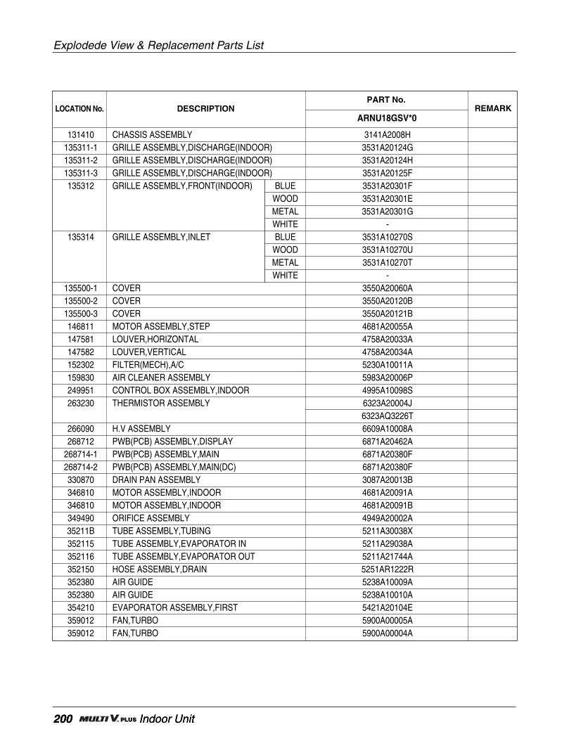
200 Indoor Unit
Explodede View & Replacement Parts List
200 Indoor Unit
ARNU18GSV*0
PART No.
131410 CHASSIS ASSEMBLY 3141A2008H135311-1 GRILLE ASSEMBLY,DISCHARGE(INDOOR) 3531A20124G135311-2 GRILLE ASSEMBLY,DISCHARGE(INDOOR) 3531A20124H135311-3 GRILLE ASSEMBLY,DISCHARGE(INDOOR) 3531A20125F135312 GRILLE ASSEMBLY,FRONT(INDOOR) BLUE 3531A20301F
WOOD 3531A20301EMETAL 3531A20301GWHITE -
135314 GRILLE ASSEMBLY,INLET BLUE 3531A10270SWOOD 3531A10270UMETAL 3531A10270TWHITE -
135500-1 COVER 3550A20060A135500-2 COVER 3550A20120B135500-3 COVER 3550A20121B146811 MOTOR ASSEMBLY,STEP 4681A20055A147581 LOUVER,HORIZONTAL 4758A20033A147582 LOUVER,VERTICAL 4758A20034A152302 FILTER(MECH),A/C 5230A10011A159830 AIR CLEANER ASSEMBLY 5983A20006P249951 CONTROL BOX ASSEMBLY,INDOOR 4995A10098S263230 THERMISTOR ASSEMBLY 6323A20004J
6323AQ3226T266090 H.V ASSEMBLY 6609A10008A268712 PWB(PCB) ASSEMBLY,DISPLAY 6871A20462A
268714-1 PWB(PCB) ASSEMBLY,MAIN 6871A20380F268714-2 PWB(PCB) ASSEMBLY,MAIN(DC) 6871A20380F330870 DRAIN PAN ASSEMBLY 3087A20013B346810 MOTOR ASSEMBLY,INDOOR 4681A20091A346810 MOTOR ASSEMBLY,INDOOR 4681A20091B349490 ORIFICE ASSEMBLY 4949A20002A35211B TUBE ASSEMBLY,TUBING 5211A30038X352115 TUBE ASSEMBLY,EVAPORATOR IN 5211A29038A352116 TUBE ASSEMBLY,EVAPORATOR OUT 5211A21744A352150 HOSE ASSEMBLY,DRAIN 5251AR1222R352380 AIR GUIDE 5238A10009A352380 AIR GUIDE 5238A10010A354210 EVAPORATOR ASSEMBLY,FIRST 5421A20104E359012 FAN,TURBO 5900A00005A359012 FAN,TURBO 5900A00004A
LOCATION No. DESCRIPTION REMARK

Service Manual 201
Explodede View & Replacement Parts List
B1
152302
336600-2
359012
346810-2
346810-1
336600-1
263230-1
263230-2
263230-3
158591
352150
352118354210
330870
268714-1
249951
268714-2
55211G
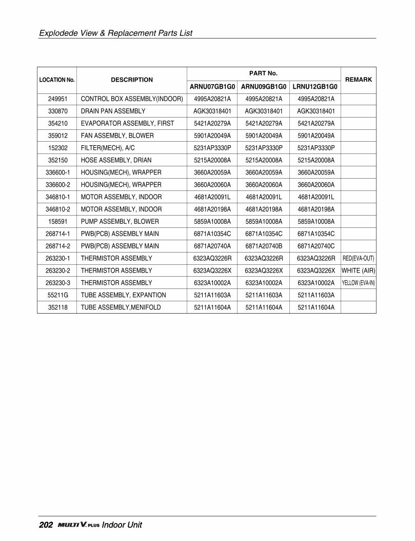
202 Indoor Unit
Explodede View & Replacement Parts List
202 Indoor Unit
ARNU07GB1G0 ARNU09GB1G0 LRNU12GB1G0
PART No.
249951 CONTROL BOX ASSEMBLY(INDOOR) 4995A20821A 4995A20821A 4995A20821A
330870 DRAIN PAN ASSEMBLY AGK30318401 AGK30318401 AGK30318401
354210 EVAPORATOR ASSEMBLY, FIRST 5421A20279A 5421A20279A 5421A20279A
359012 FAN ASSEMBLY, BLOWER 5901A20049A 5901A20049A 5901A20049A
152302 FILTER(MECH), A/C 5231AP3330P 5231AP3330P 5231AP3330P
352150 HOSE ASSEMBLY, DRIAN 5215A20008A 5215A20008A 5215A20008A
336600-1 HOUSING(MECH), WRAPPER 3660A20059A 3660A20059A 3660A20059A
336600-2 HOUSING(MECH), WRAPPER 3660A20060A 3660A20060A 3660A20060A
346810-1 MOTOR ASSEMBLY, INDOOR 4681A20091L 4681A20091L 4681A20091L
346810-2 MOTOR ASSEMBLY, INDOOR 4681A20198A 4681A20198A 4681A20198A
158591 PUMP ASSEMBLY, BLOWER 5859A10008A 5859A10008A 5859A10008A
268714-1 PWB(PCB) ASSEMBLY MAIN 6871A10354C 6871A10354C 6871A10354C
268714-2 PWB(PCB) ASSEMBLY MAIN 6871A20740A 6871A20740B 6871A20740C
263230-1 THERMISTOR ASSEMBLY 6323AQ3226R 6323AQ3226R 6323AQ3226R RED(EVA-OUT)
263230-2 THERMISTOR ASSEMBLY 6323AQ3226X 6323AQ3226X 6323AQ3226X WHITE (AIR)
263230-3 THERMISTOR ASSEMBLY 6323A10002A 6323A10002A 6323A10002A YELLOW (EVA-IN)
55211G TUBE ASSEMBLY, EXPANTION 5211A11603A 5211A11603A 5211A11603A
352118 TUBE ASSEMBLY,MENIFOLD 5211A11604A 5211A11604A 5211A11604A
LOCATION No. DESCRIPTION REMARK

Service Manual 203
Explodede View & Replacement Parts List
B2
152302
336600-1
263230-1
263230-2
263230-3
158591
330870
359012
352150
352118354210
268714-1
249951
268714-2
55211G
336600-2
346810

204 Indoor Unit
Explodede View & Replacement Parts List
204 Indoor Unit
ARNU18GB2G0 ARNU24GB2G0
PART No.
249951 Case Assembly, Control(Indoor) 4995A20821A 4995A20821A
354210 Evaporator Assembly, First 5421A20280A 5421A20280A
359012 Fan Assembly, Blower 5901A20049A 5901A20049A
152302 Filter Assembly, Air Cleaner 5231AP3330Q 5231AP3330Q
352150 Hose Assembly, Drain 5215A20008A 5215A20008A
336600-1 Housing, Wrapper 3660A20059A 3660A20059A
336600-2 Housing, Wrapper 3660A20060A 3660A20060A
346810 Motor Assembly, DC, Indoor 4681A20198A 4681A20198A
330870 Pan, Drain 3086A20039A 3086A20039A
268714-1 PCB Assembly, Main 6871A10354C 6871A10354C
268714-2 PCB Assembly, Main 6871A20740E 6871A20740G EEP-ROM PCB
158591 Pump Assembly, Water 5859A10008A 5859A10008A
263230-1 Thermistor, NTC 6323AQ3226R 6323AQ3226R RED(EVA-OUT)
263230-2 Thermistor, NTC 6323A10002A 6323A10002A WHITE(AIR)
263230-3 Thermistor, NTC 6323AQ3226X 6323AQ3226X YELLOW(EVA-IN)
55211G Tube Assembly, Expansion 5211A11603C 5211A11603B EVA-IN
352118 Tube Assembly, Menifold(Indoor) 5211A11604C 5211A11604B EVA-OUT
LOCATION No. DESCRIPTION REMARK
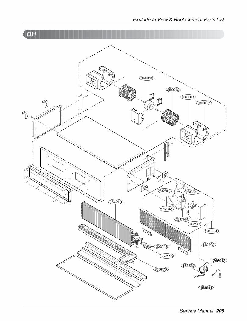
Service Manual 205
Explodede View & Replacement Parts List
359012
354210
352115
152302352118
330870
268714-1
249951
336600-2
263230-3
263230-1
336600-1
266012
158591
158580
263230-2
346810
268714-2
BH
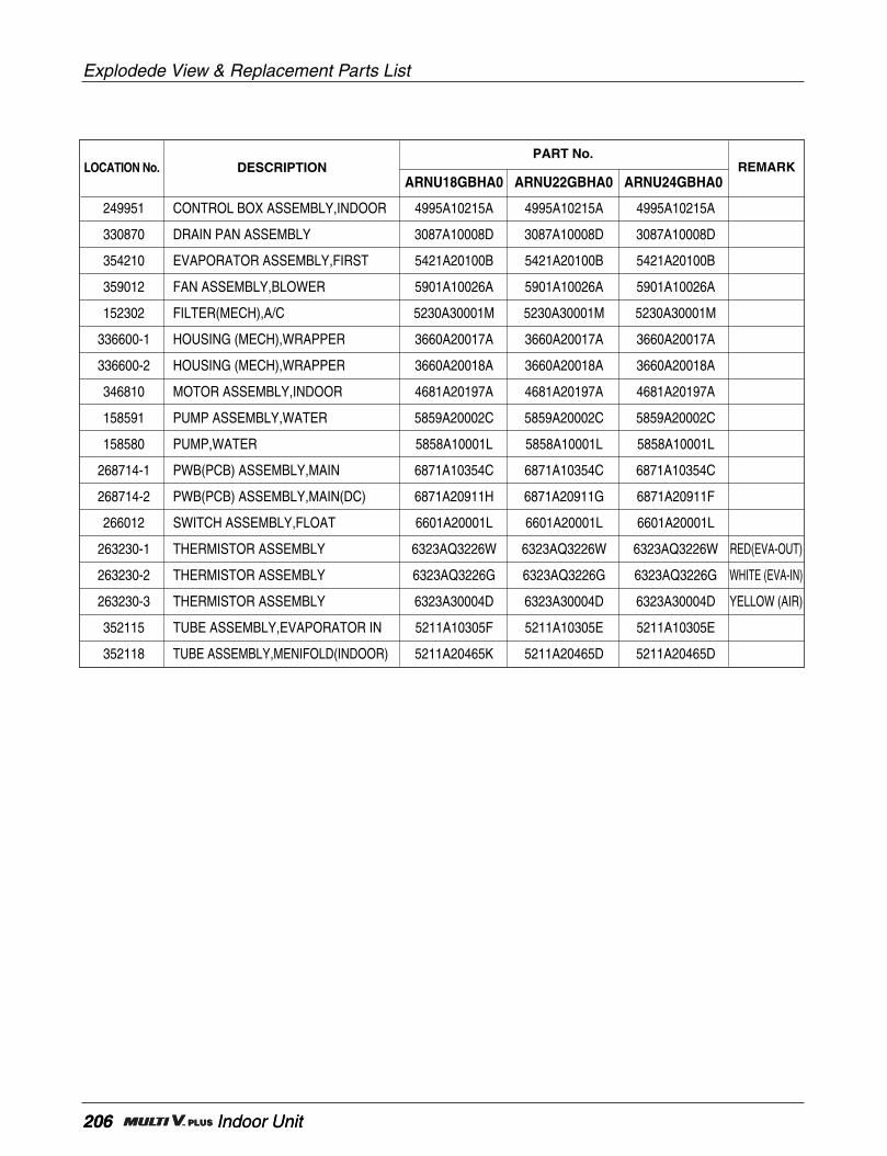
206 Indoor Unit
Explodede View & Replacement Parts List
206 Indoor Unit
ARNU18GBHA0 ARNU22GBHA0 ARNU24GBHA0
PART No.
249951 CONTROL BOX ASSEMBLY,INDOOR 4995A10215A 4995A10215A 4995A10215A
330870 DRAIN PAN ASSEMBLY 3087A10008D 3087A10008D 3087A10008D
354210 EVAPORATOR ASSEMBLY,FIRST 5421A20100B 5421A20100B 5421A20100B
359012 FAN ASSEMBLY,BLOWER 5901A10026A 5901A10026A 5901A10026A
152302 FILTER(MECH),A/C 5230A30001M 5230A30001M 5230A30001M
336600-1 HOUSING (MECH),WRAPPER 3660A20017A 3660A20017A 3660A20017A
336600-2 HOUSING (MECH),WRAPPER 3660A20018A 3660A20018A 3660A20018A
346810 MOTOR ASSEMBLY,INDOOR 4681A20197A 4681A20197A 4681A20197A
158591 PUMP ASSEMBLY,WATER 5859A20002C 5859A20002C 5859A20002C
158580 PUMP,WATER 5858A10001L 5858A10001L 5858A10001L
268714-1 PWB(PCB) ASSEMBLY,MAIN 6871A10354C 6871A10354C 6871A10354C
268714-2 PWB(PCB) ASSEMBLY,MAIN(DC) 6871A20911H 6871A20911G 6871A20911F
266012 SWITCH ASSEMBLY,FLOAT 6601A20001L 6601A20001L 6601A20001L
263230-1 THERMISTOR ASSEMBLY 6323AQ3226W 6323AQ3226W 6323AQ3226W RED(EVA-OUT)
263230-2 THERMISTOR ASSEMBLY 6323AQ3226G 6323AQ3226G 6323AQ3226G WHITE (EVA-IN)
263230-3 THERMISTOR ASSEMBLY 6323A30004D 6323A30004D 6323A30004D YELLOW (AIR)
352115 TUBE ASSEMBLY,EVAPORATOR IN 5211A10305F 5211A10305E 5211A10305E
352118 TUBE ASSEMBLY,MENIFOLD(INDOOR) 5211A20465K 5211A20465D 5211A20465D
LOCATION No. DESCRIPTION REMARK

Service Manual 207
Explodede View & Replacement Parts List
359012
354210
35211G
152302352118
268714-1
249951
336600-2
263230-3
263230-1
336600-1
266012
158591
158580
263230-2
268714-3
268714-2
346810
346810
359012
BG
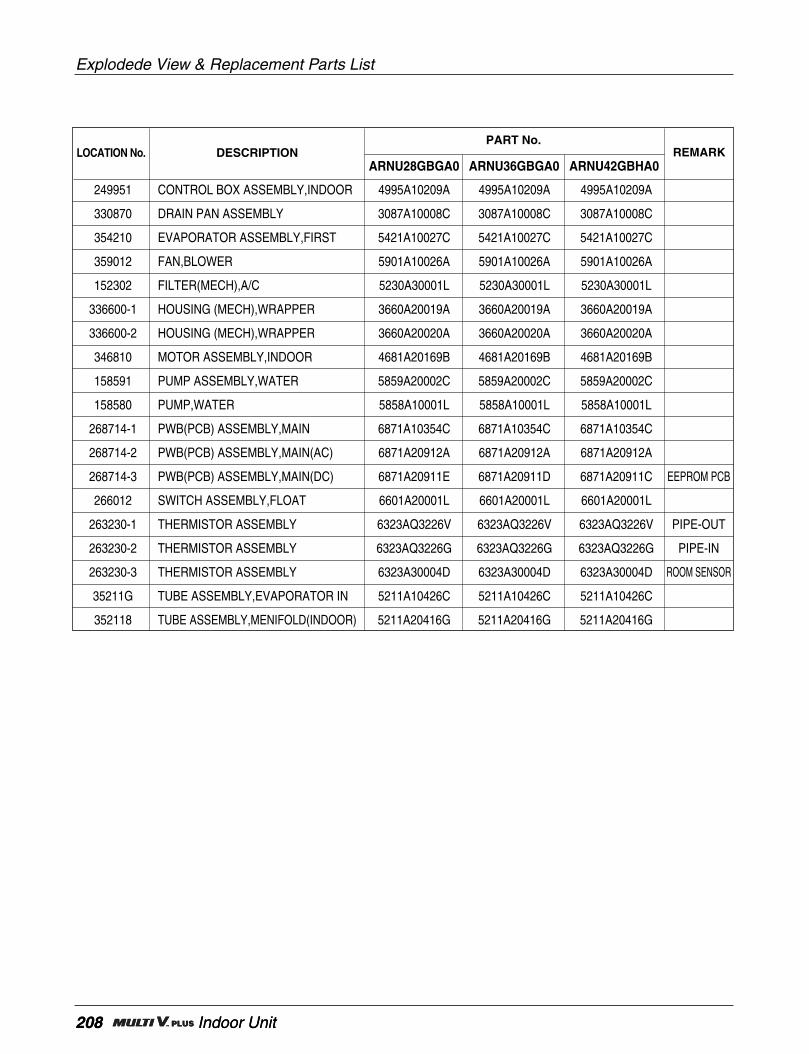
208 Indoor Unit
Explodede View & Replacement Parts List
208 Indoor Unit
ARNU28GBGA0 ARNU36GBGA0 ARNU42GBHA0
PART No.
249951 CONTROL BOX ASSEMBLY,INDOOR 4995A10209A 4995A10209A 4995A10209A
330870 DRAIN PAN ASSEMBLY 3087A10008C 3087A10008C 3087A10008C
354210 EVAPORATOR ASSEMBLY,FIRST 5421A10027C 5421A10027C 5421A10027C
359012 FAN,BLOWER 5901A10026A 5901A10026A 5901A10026A
152302 FILTER(MECH),A/C 5230A30001L 5230A30001L 5230A30001L
336600-1 HOUSING (MECH),WRAPPER 3660A20019A 3660A20019A 3660A20019A
336600-2 HOUSING (MECH),WRAPPER 3660A20020A 3660A20020A 3660A20020A
346810 MOTOR ASSEMBLY,INDOOR 4681A20169B 4681A20169B 4681A20169B
158591 PUMP ASSEMBLY,WATER 5859A20002C 5859A20002C 5859A20002C
158580 PUMP,WATER 5858A10001L 5858A10001L 5858A10001L
268714-1 PWB(PCB) ASSEMBLY,MAIN 6871A10354C 6871A10354C 6871A10354C
268714-2 PWB(PCB) ASSEMBLY,MAIN(AC) 6871A20912A 6871A20912A 6871A20912A
268714-3 PWB(PCB) ASSEMBLY,MAIN(DC) 6871A20911E 6871A20911D 6871A20911C EEPROM PCB
266012 SWITCH ASSEMBLY,FLOAT 6601A20001L 6601A20001L 6601A20001L
263230-1 THERMISTOR ASSEMBLY 6323AQ3226V 6323AQ3226V 6323AQ3226V PIPE-OUT
263230-2 THERMISTOR ASSEMBLY 6323AQ3226G 6323AQ3226G 6323AQ3226G PIPE-IN
263230-3 THERMISTOR ASSEMBLY 6323A30004D 6323A30004D 6323A30004D ROOM SENSOR
35211G TUBE ASSEMBLY,EVAPORATOR IN 5211A10426C 5211A10426C 5211A10426C
352118 TUBE ASSEMBLY,MENIFOLD(INDOOR) 5211A20416G 5211A20416G 5211A20416G
LOCATION No. DESCRIPTION REMARK
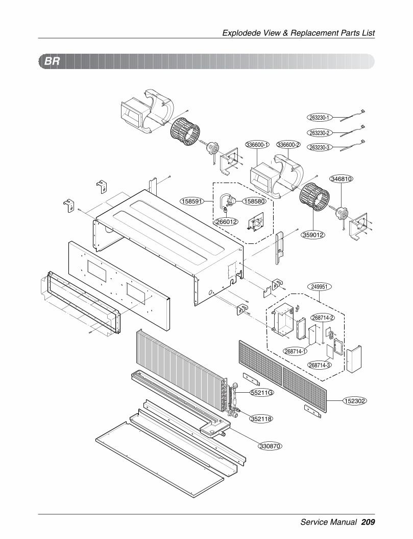
Service Manual 209
Explodede View & Replacement Parts List
BR
55211G
158580158591
152302
330870
268714-1
268714-3
268714-2
249951
346810
359012
266012
336600-2336600-1
352118
263230-1
263230-2
263230-3

210 Indoor Unit
Explodede View & Replacement Parts List
210 Indoor Unit
ARNU48GBRA0
PART No.
249951 CASE ASSEMBLY, CONTROL(INDOOR) 4995A10209B
330870 DRAIN PAN ASSEMBLY 3087A20025B
354210 EVAPORATOR ASSEMBLY, FIRST 5421A20273A
359012 FAN ASSY, BLOWER 5901A10051A
152302 FILTER(MECH), A/C 5230A30077A
336600-1 HOUSING (MECH), WRAPPER 3660A20044A
336600-2 HOUSING (MECH), WRAPPER 3660A20045A
346810 MOTOR ASSEMBLY, INDOOR 4681A20169B
158591 PUMP ASSEMBLY, WATER 5859A20002C
158580 PUMP, WATER 5858A10001L
268714-1 PWB(PCB) ASSEMBLY, MAIN 6871A10354C
268714-2 PWB(PCB) ASSEMBLY, MAIN(AC) 6871A20912A
268714-3 PWB(PCB) ASSEMBLY, MAIN(DC) 6871A20911K EEPROM PCB
266012 SWITCH ASSEMBLY, FLOAT 6601A20001L
263230-1 THERMISTOR ASSEMBLY 6323AQ3226V PIPE-OUT
263230-2 THERMISTOR ASSEMBLY 6323AQ3226E PIPE-IN
263230-3 THERMISTOR ASSEMBLY 6323A30004D ROOM SENSOR
35211G TUBE ASSEMBLY, EVAPORATOR IN 5211A21810A
352118 TUBE ASSEMBLY, MENIFOLD(INDOOR) 5211A21811B
LOCATION No. DESCRIPTION REMARK

Service Manual 211
Explodede View & Replacement Parts List
SE1 (Standard)
152302
342800
263230-2263230-1
359011
131410 733010
135312
135311
159901
146811
346810
13551635211B
352150
268713
354210
249951 268714
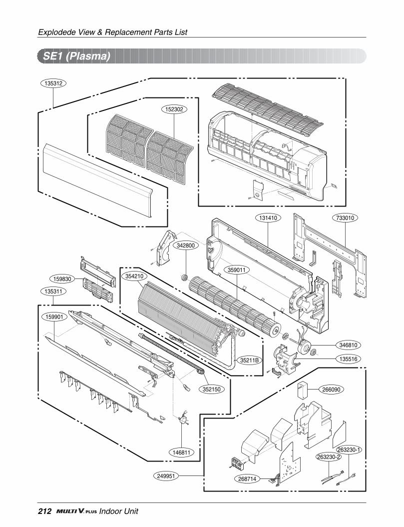
212 Indoor Unit
Explodede View & Replacement Parts List
SE1 (Plasma)
152302
342800
263230-2263230-1
359011
131410 733010
135312
135311
159901
146811
346810
266090
13551635211B
352150
354210159830
249951 268714
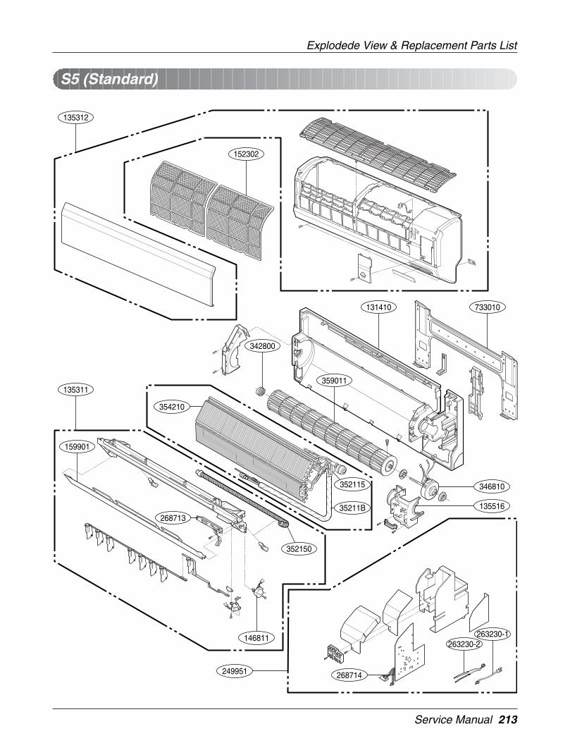
Service Manual 213
Explodede View & Replacement Parts List
S5 (Standard)
152302
342800
263230-2263230-1
359011
131410 733010
135312
135311
159901
146811
346810
13551635211B
352115
352150
268713
354210
249951 268714
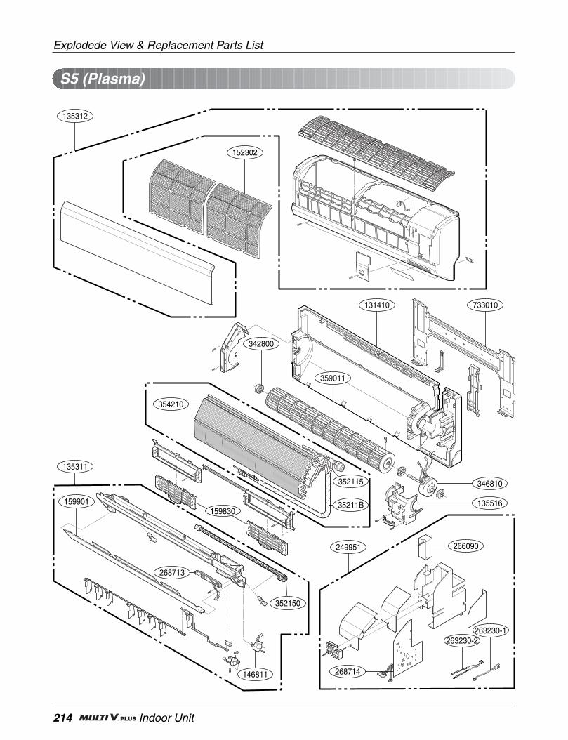
214 Indoor Unit
Explodede View & Replacement Parts List
S5 (Plasma)
152302
342800
263230-2263230-1
359011
131410 733010
135312
135311
159901
146811
346810
266090
13551635211B
352115
352150
268713
354210
249951
268714
159830
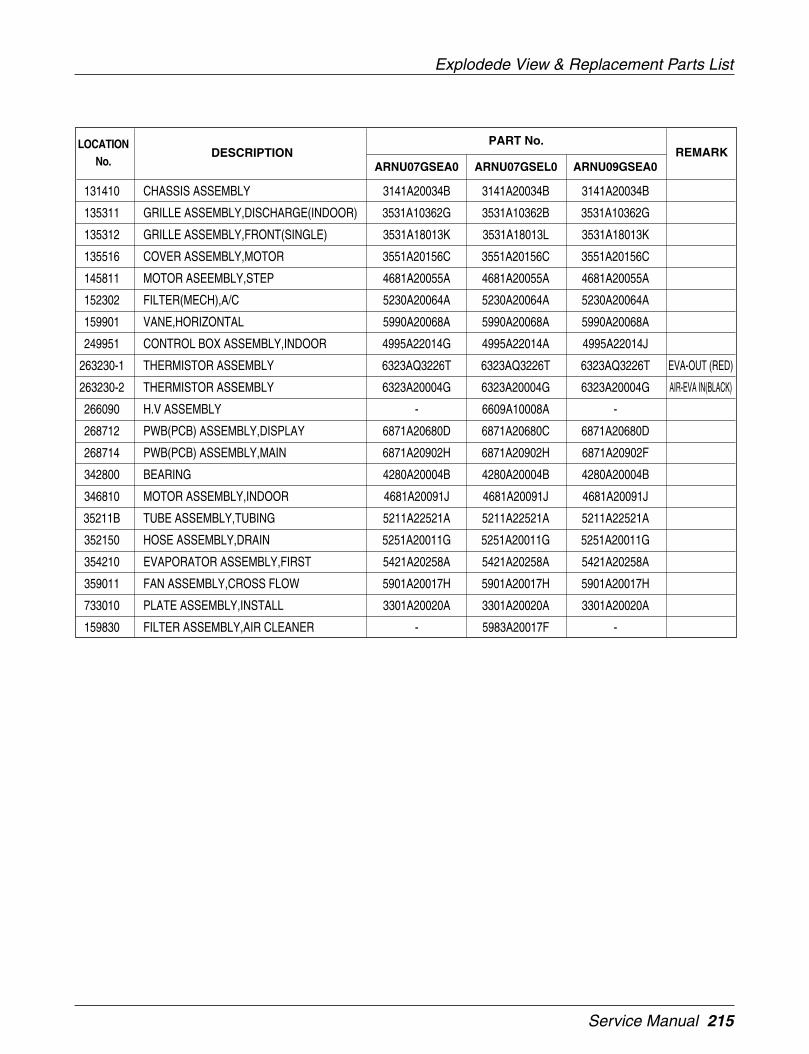
Service Manual 215
Explodede View & Replacement Parts List
PART No.
131410 CHASSIS ASSEMBLY 3141A20034B 3141A20034B 3141A20034B
135311 GRILLE ASSEMBLY,DISCHARGE(INDOOR) 3531A10362G 3531A10362B 3531A10362G
135312 GRILLE ASSEMBLY,FRONT(SINGLE) 3531A18013K 3531A18013L 3531A18013K
135516 COVER ASSEMBLY,MOTOR 3551A20156C 3551A20156C 3551A20156C
145811 MOTOR ASEEMBLY,STEP 4681A20055A 4681A20055A 4681A20055A
152302 FILTER(MECH),A/C 5230A20064A 5230A20064A 5230A20064A
159901 VANE,HORIZONTAL 5990A20068A 5990A20068A 5990A20068A
249951 CONTROL BOX ASSEMBLY,INDOOR 4995A22014G 4995A22014A 4995A22014J
263230-1 THERMISTOR ASSEMBLY 6323AQ3226T 6323AQ3226T 6323AQ3226T EVA-OUT (RED)
263230-2 THERMISTOR ASSEMBLY 6323A20004G 6323A20004G 6323A20004G AIR-EVA IN(BLACK)
266090 H.V ASSEMBLY - 6609A10008A -
268712 PWB(PCB) ASSEMBLY,DISPLAY 6871A20680D 6871A20680C 6871A20680D
268714 PWB(PCB) ASSEMBLY,MAIN 6871A20902H 6871A20902H 6871A20902F
342800 BEARING 4280A20004B 4280A20004B 4280A20004B
346810 MOTOR ASSEMBLY,INDOOR 4681A20091J 4681A20091J 4681A20091J
35211B TUBE ASSEMBLY,TUBING 5211A22521A 5211A22521A 5211A22521A
352150 HOSE ASSEMBLY,DRAIN 5251A20011G 5251A20011G 5251A20011G
354210 EVAPORATOR ASSEMBLY,FIRST 5421A20258A 5421A20258A 5421A20258A
359011 FAN ASSEMBLY,CROSS FLOW 5901A20017H 5901A20017H 5901A20017H
733010 PLATE ASSEMBLY,INSTALL 3301A20020A 3301A20020A 3301A20020A
159830 FILTER ASSEMBLY,AIR CLEANER - 5983A20017F -
LOCATIONNo.
DESCRIPTION REMARKARNU07GSEA0 ARNU07GSEL0 ARNU09GSEA0
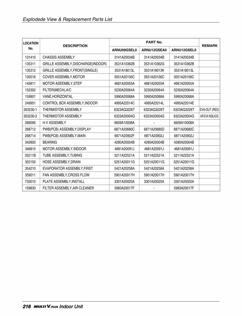
216 Indoor Unit
Explodede View & Replacement Parts List
216 Indoor Unit216 Indoor Unit
PART No.
131410 CHASSIS ASSEMBLY 3141A20034B 3141A20034B 3141A20034B
135311 GRILLE ASSEMBLY,DISCHARGE(INDOOR) 3531A10362B 3531A10362G 3531A10362B
135312 GRILLE ASSEMBLY,FRONT(SINGLE) 3531A18013L 3531A18013K 3531A18013L
135516 COVER ASSEMBLY,MOTOR 3551A20156C 3551A20156C 3551A20156C
145811 MOTOR ASEEMBLY,STEP 4681A20055A 4681A20055A 4681A20055A
152302 FILTER(MECH),A/C 5230A20064A 5230A20064A 5230A20064A
159901 VANE,HORIZONTAL 5990A20068A 5990A20068A 5990A20068A
249951 CONTROL BOX ASSEMBLY,INDOOR 4995A22014C 4995A22014L 4995A22014E
263230-1 THERMISTOR ASSEMBLY 6323AQ3226T 6323AQ3226T 6323AQ3226T EVA-OUT (RED)
263230-2 THERMISTOR ASSEMBLY 6323A20004G 6323A20004G 6323A20004G AIR-EVA IN(BLACK)
266090 H.V ASSEMBLY 6609A10008A - 6609A10008A
268712 PWB(PCB) ASSEMBLY,DISPLAY 6871A20680C 6871A20680D 6871A20680C
268714 PWB(PCB) ASSEMBLY,MAIN 6871A20902F 6871A20902J 6871A20902J
342800 BEARING 4280A20004B 4280A20004B 4280A20004B
346810 MOTOR ASSEMBLY,INDOOR 4681A20091J 4681A20091J 4681A20091J
35211B TUBE ASSEMBLY,TUBING 5211A22521A 5211A22521A 5211A22521A
352150 HOSE ASSEMBLY,DRAIN 5251A20011G 5251A20011G 5251A20011G
354210 EVAPORATOR ASSEMBLY,FIRST 5421A20258A 5421A20258A 5421A20258A
359011 FAN ASSEMBLY,CROSS FLOW 5901A20017H 5901A20017H 5901A20017H
733010 PLATE ASSEMBLY,INSTALL 3301A20020A 3301A20020A 3301A20020A
159830 FILTER ASSEMBLY,AIR CLEANER 5983A20017F - 5983A20017F
LOCATIONNo.
DESCRIPTION REMARKARNU09GSEL0 ARNU12GSEA0 ARNU12GSEL0

Service Manual 217
Explodede View & Replacement Parts List
PART No.
131410 CHASSIS ASSEMBLY 3141A20020F 3141A20020F 3141A20020F 3141A20020F
135311 GRILLE ASSEMBLY,DISCHARGE(INDOOR) 3531A20252V 3531A20252L 3531A20252V 3531A20252L
135312 GRILLE ASSEMBLY,FRONT(SINGLE) 3531A23005T 3531A23005U 3531A23005T 3531A23005U
135516 COVER ASSEMBLY,MOTOR 3551A20154A 3551A20154A 3551A20154A 3551A20154A
145811 MOTOR ASEEMBLY,STEP 4681A20055A 4681A20055A 4681A20055A 4681A20055A
152302 FILTER(MECH),A/C 5230A20052B 5230A20052B 5230A20052B 5230A20052B
159901 VANE,HORIZONTAL 5990A20071A 5990A20071A 5990A20071A 5990A20071A
249951 CONTROL BOX ASSEMBLY,INDOOR 4995A22016E 4995A22016B 4995A22016D 4995A22016A
263230-1 THERMISTOR ASSEMBLY 6323AQ3226T 6323AQ3226T 6323AQ3226T 6323AQ3226T EVA-OUT (RED)
263230-2 THERMISTOR ASSEMBLY 6323A20004G 6323A20004G 6323A20004G 6323A20004G AIR-EVA IN(BLACK)
266090 H.V ASSEMBLY - 6609A10008A - 6609A10008A
268712 PWB(PCB) ASSEMBLY,DISPLAY 6871A20681D 6871A20681C 6871A20681D 6871A20681C
268714 PWB(PCB) ASSEMBLY,MAIN 6871A20902B 6871A20902B 6871A20902A 6871A20902A
342800 BEARING 4280A20004A 4280A20004A 4280A20004A 4280A20004A
346810 MOTOR ASSEMBLY,INDOOR 4681A20091J 4681A20091J 4681A20091J 4681A20091J
35211B TUBE ASSEMBLY,TUBING 5211A23366B 5211A23366B 5211A23366A 5211A23366A
352115 TUBE ASSEMBLY,EVAPORATOR IN 5211A19008B 5211A19008B 5211A19008A 5211A19008A
352150 HOSE ASSEMBLY,DRAIN 5251A20011D 5251A20011D 5251A20011D 5251A20011D
354210 EVAPORATOR ASSEMBLY,FIRST 5421A20220A 5421A20220A 5421A20220A 5421A20220A
359011 FAN ASSEMBLY,CROSS FLOW 5901A92441E 5901A92441E 5901A92441E 5901A92441E
733010 PLATE ASSEMBLY,INSTALL 3301A20020B 3301A20020B 3301A20020B 3301A20020B
159830 FILTER ASSEMBLY,AIR CLEANER - 5983A20018A - 5983A20018A
LOCATIONNo.
DESCRIPTION REMARKARNU18GS5A0 ARNU18GS5L0 ARNU24GS5A0 ARNU24GS5L0
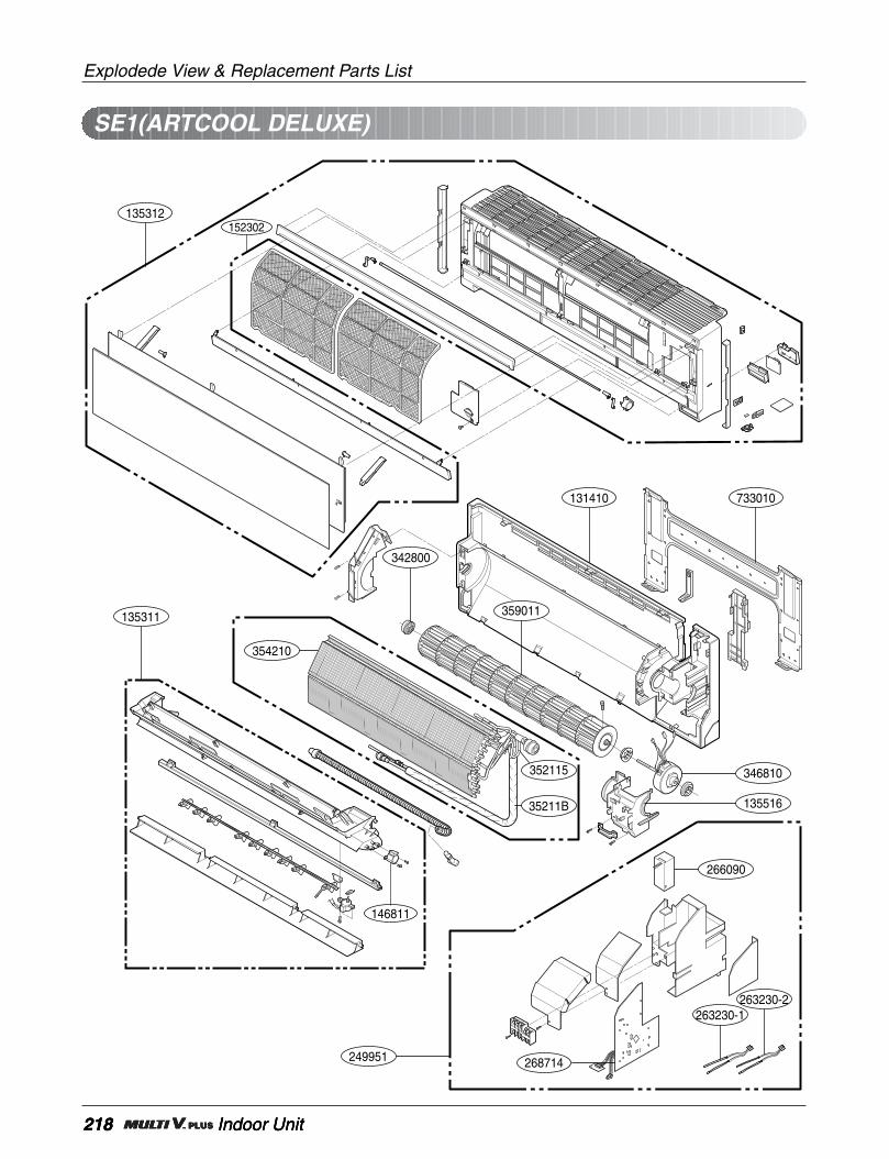
218 Indoor Unit
Explodede View & Replacement Parts List
218 Indoor Unit218 Indoor Unit
SE1(ARTCOOL DELUXE)
342800
263230-1263230-2
359011
131410 733010
135312
135311
346810
266090
13551635211B
352115
354210
249951 268714
152302
146811
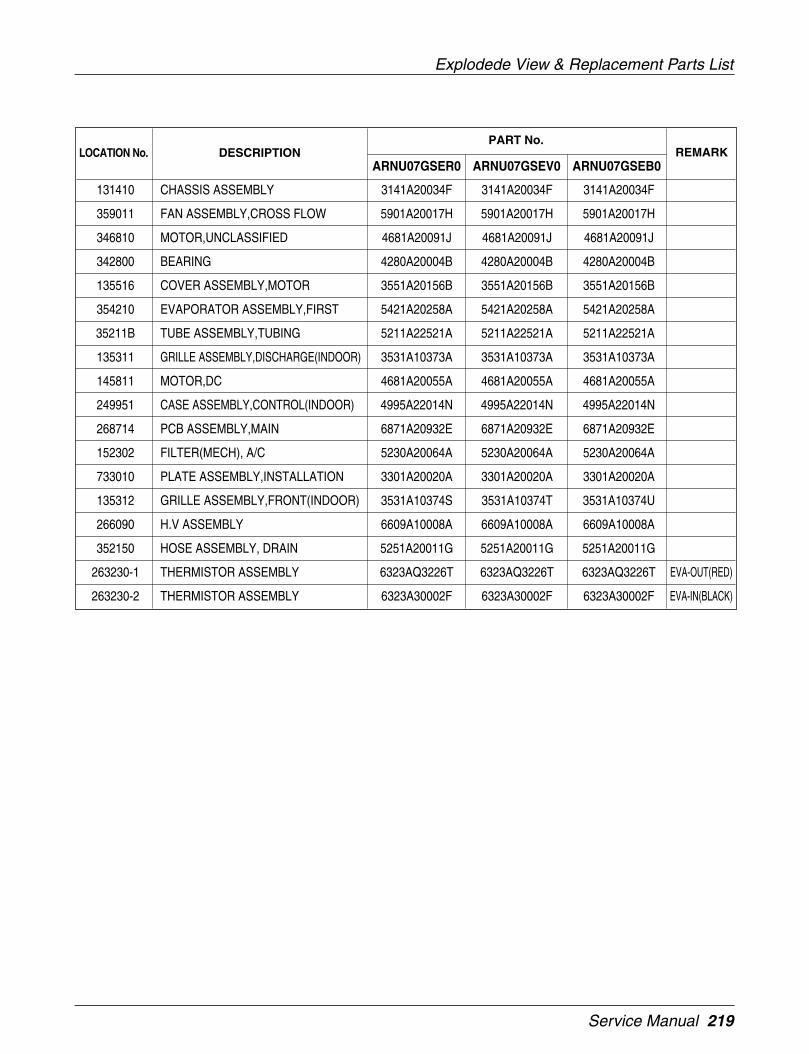
Service Manual 219
Explodede View & Replacement Parts List
ARNU07GSER0 ARNU07GSEV0 ARNU07GSEB0
PART No.
131410 CHASSIS ASSEMBLY 3141A20034F 3141A20034F 3141A20034F
359011 FAN ASSEMBLY,CROSS FLOW 5901A20017H 5901A20017H 5901A20017H
346810 MOTOR,UNCLASSIFIED 4681A20091J 4681A20091J 4681A20091J
342800 BEARING 4280A20004B 4280A20004B 4280A20004B
135516 COVER ASSEMBLY,MOTOR 3551A20156B 3551A20156B 3551A20156B
354210 EVAPORATOR ASSEMBLY,FIRST 5421A20258A 5421A20258A 5421A20258A
35211B TUBE ASSEMBLY,TUBING 5211A22521A 5211A22521A 5211A22521A
135311 GRILLE ASSEMBLY,DISCHARGE(INDOOR) 3531A10373A 3531A10373A 3531A10373A
145811 MOTOR,DC 4681A20055A 4681A20055A 4681A20055A
249951 CASE ASSEMBLY,CONTROL(INDOOR) 4995A22014N 4995A22014N 4995A22014N
268714 PCB ASSEMBLY,MAIN 6871A20932E 6871A20932E 6871A20932E
152302 FILTER(MECH), A/C 5230A20064A 5230A20064A 5230A20064A
733010 PLATE ASSEMBLY,INSTALLATION 3301A20020A 3301A20020A 3301A20020A
135312 GRILLE ASSEMBLY,FRONT(INDOOR) 3531A10374S 3531A10374T 3531A10374U
266090 H.V ASSEMBLY 6609A10008A 6609A10008A 6609A10008A
352150 HOSE ASSEMBLY, DRAIN 5251A20011G 5251A20011G 5251A20011G
263230-1 THERMISTOR ASSEMBLY 6323AQ3226T 6323AQ3226T 6323AQ3226T EVA-OUT(RED)
263230-2 THERMISTOR ASSEMBLY 6323A30002F 6323A30002F 6323A30002F EVA-IN(BLACK)
LOCATION No. DESCRIPTION REMARK
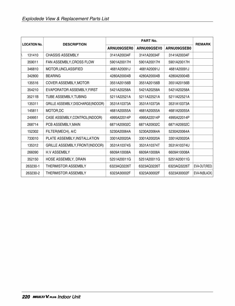
220 Indoor Unit
Explodede View & Replacement Parts List
220 Indoor Unit220 Indoor Unit
ARNU09GSER0 ARNU09GSEV0 ARNU09GSEB0
PART No.
\ 131410 CHASSIS ASSEMBLY 3141A20034F 3141A20034F 3141A20034F
359011 FAN ASSEMBLY,CROSS FLOW 5901A20017H 5901A20017H 5901A20017H
346810 MOTOR,UNCLASSIFIED 4681A20091J 4681A20091J 4681A20091J
342800 BEARING 4280A20004B 4280A20004B 4280A20004B
135516 COVER ASSEMBLY,MOTOR 3551A20156B 3551A20156B 3551A20156B
354210 EVAPORATOR ASSEMBLY,FIRST 5421A20258A 5421A20258A 5421A20258A
35211B TUBE ASSEMBLY,TUBING 5211A22521A 5211A22521A 5211A22521A
135311 GRILLE ASSEMBLY,DISCHARGE(INDOOR) 3531A10373A 3531A10373A 3531A10373A
145811 MOTOR,DC 4681A20055A 4681A20055A 4681A20055A
249951 CASE ASSEMBLY,CONTROL(INDOOR) 4995A22014P 4995A22014P 4995A22014P
268714 PCB ASSEMBLY,MAIN 6871A20932C 6871A20932C 6871A20932C
152302 FILTER(MECH), A/C 5230A20064A 5230A20064A 5230A20064A
733010 PLATE ASSEMBLY,INSTALLATION 3301A20020A 3301A20020A 3301A20020A
135312 GRILLE ASSEMBLY,FRONT(INDOOR) 3531A10374S 3531A10374T 3531A10374U
266090 H.V ASSEMBLY 6609A10008A 6609A10008A 6609A10008A
352150 HOSE ASSEMBLY, DRAIN 5251A20011G 5251A20011G 5251A20011G
263230-1 THERMISTOR ASSEMBLY 6323AQ3226T 6323AQ3226T 6323AQ3226T EVA-OUT(RED)
263230-2 THERMISTOR ASSEMBLY 6323A30002F 6323A30002F 6323A30002F EVA-IN(BLACK)
LOCATION No. DESCRIPTION REMARK

Service Manual 221
Explodede View & Replacement Parts List
ARNU12GSER0 ARNU12GSEV0 ARNU12GSEB0
PART No.
131410 CHASSIS ASSEMBLY 3141A20034F 3141A20034F 3141A20034F
359011 FAN ASSEMBLY,CROSS FLOW 5901A20017H 5901A20017H 5901A20017H
346810 MOTOR,UNCLASSIFIED 4681A20091J 4681A20091J 4681A20091J
342800 BEARING 4280A20004B 4280A20004B 4280A20004B
135516 COVER ASSEMBLY,MOTOR 3551A20156B 3551A20156B 3551A20156B
354210 EVAPORATOR ASSEMBLY,FIRST 5421A20258A 5421A20258A 5421A20258A
35211B TUBE ASSEMBLY,TUBING 5211A22521A 5211A22521A 5211A22521A
135311 GRILLE ASSEMBLY,DISCHARGE(INDOOR) 3531A10373A 3531A10373A 3531A10373A
145811 MOTOR,DC 4681A20055A 4681A20055A 4681A20055A
249951 CASE ASSEMBLY,CONTROL(INDOOR) 4995A22014Q 4995A22014Q 4995A22014Q
268714 PCB ASSEMBLY,MAIN 6871A20932A 6871A20932A 6871A20932A
152302 FILTER(MECH), A/C 5230A20064A 5230A20064A 5230A20064A
733010 PLATE ASSEMBLY,INSTALLATION 3301A20020A 3301A20020A 3301A20020A
135312 GRILLE ASSEMBLY,FRONT(INDOOR) 3531A10374S 3531A10374T 3531A10374U
266090 H.V ASSEMBLY 6609A10008A 6609A10008A 6609A10008A
352150 HOSE ASSEMBLY, DRAIN 5251A20011G 5251A20011G 5251A20011G
263230-1 THERMISTOR ASSEMBLY 6323AQ3226T 6323AQ3226T 6323AQ3226T EVA-OUT(RED)
263230-2 THERMISTOR ASSEMBLY 6323A30002F 6323A30002F 6323A30002F EVA-IN(BLACK)
LOCATION No. DESCRIPTION REMARK

Explodede View & Replacement Parts List
222 Outdoor Unit
151310
548490
554160
552117
554160
553000-1 553000-1
552200-1
W52240-1
W52240-1
559990
55211G-1
552201-2
W52240-1
159910
55211G-2
W52240-3
552200-2
165010-1552116
552203-2
552203-1
W52240-2
552204-1
561410-3
552204-1
561410-2
561410-6
552202
552201-1
165010-2
552204-2
561410-5
558511
552204-1
561410-4552204-1
561410-1
263230-2
263230-1
263230-3
352112
352111
352111W52240-1
W52240-1
559990
(Thermistor)
(Thermistor)
(Thermistor)
UV2CYCLE PARTS
laegoo
159910
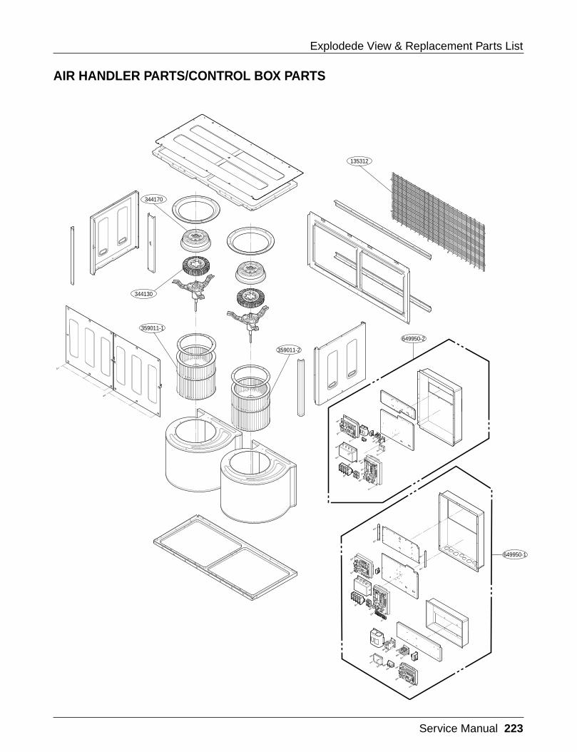
Service Manual 223
Explodede View & Replacement Parts List
344170
135312
344130
359011-1
359011-2
649950-2
649950-1
AIR HANDLER PARTS/CONTROL BOX PARTS
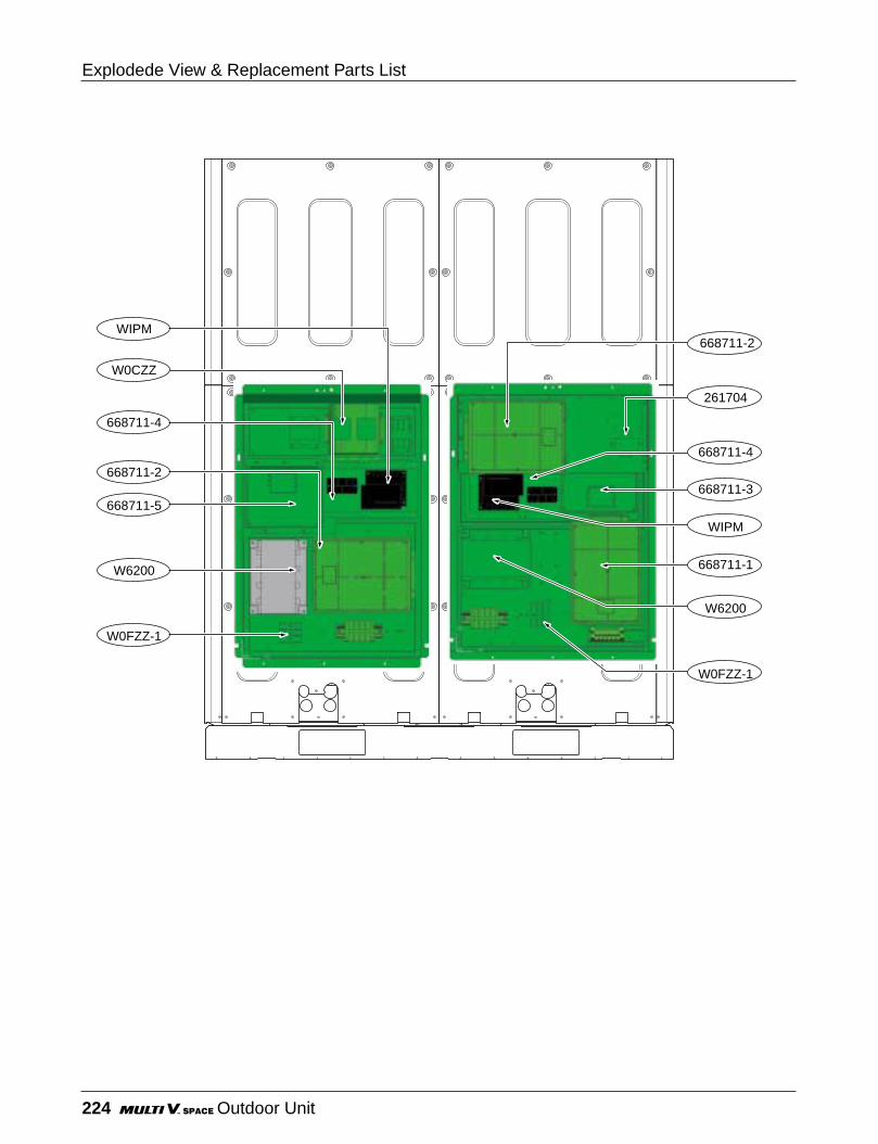
Explodede View & Replacement Parts List
224 Outdoor Unit
W6200
668711-2
668711-5
668711-4
W0CZZ
W0FZZ-1
WIPM
W6200
668711-1
668711-2
668711-3
WIPM
668711-4
261704
W0FZZ-1

Service Manual 225
Explodede View & Replacement Parts List
ARUN1008F20
PART No.
135310 GRILLE ASSEMBLY,FRONT(OUTDOOR) 3531A10375B LOWER566000 SWITCH,PRESSURE 6600L000013
W52240-1 STRAINER 5224A20005N552114 TUBE ASSEMBLY,DISCHARGE(OUTDOOR) 5211A10671A O/S554160 COMPRESSOR 5416A90008K
553000-1 HEATER,SUMP 2A00093V553000-2 HEATER,SUMP 2A00093W548490 ACCUMULATOR ASSEMBLY(MECH) 4849A10053A352112 TUBE ASSEMBLY,COUPLING 5211A17100A C/V
552201-1 VALVE,CHECK 3A01020L352111 TUBE ASSEMBLY,CONNECTOR 5211A24135A O/EQUAL552117 TUBE ASSEMBLY,SUCTION(OUTDOOR) 5211A10670A
552204-1 VALVE,SOLENOID 5220A90002H561410-1 COIL ASSEMBLY,SOLENOID 6141A20050D BLUE561410-2 COIL ASSEMBLY,SOLENOID 6141A20050E ORANGE561410-3 COIL ASSEMBLY,SOLENOID 6141A20050C GRAY561410-4 COIL ASSEMBLY,SOLENOID 6141A20050B RED552116 TUBE ASSEMBLY,REVERSING 5211A12100A
W52240-2 STRAINER 5224A20005A561410-6 COIL ASSEMBLY,REVERSING VALVE 6141A20010F552202 VALVE,REVERSING 5220A20039A
165010-1 SENSOR ASSEMBLY 6501A20004G H/PRESS165010-2 SENSOR ASSEMBLY 6501A20004H L/PRESS552204-2 VALVE,SOLENOID 5220A90007B H/GAS561410-5 COIL ASSEMBLY,SOLENOID 6141A20050A GREEN55211G-1 TUBE ASSEMBLY,EXPANSION 5211A10672A MAIN552200-1 VALVE,EXPANSION BODY 5224A20004H552201-2 VALVE,CHECK 3A01020D55211G-2 TUBE ASSEMBLY,EXPANSION 5211A11600A SUBCOOLER552200-2 VALVE,EXPANSION BODY 5220A20039A SUBCOOLER561411 COIL ASSEMBLY,EXPANSION 6141A20050A SUBCOOLER558511 DRIER ASSEMBLY 5851A20002A
W52240-3 STRAINER 5220A20005D552203-1 VALVE,SERVICE 5220A90012M552203-2 VALVE,SERVICE 5220A90012K135312 GRILLE ASSEMBLY,DISCHARGE(INDOOR) 3531A10376B
649950-1 CONTROL BOX ASSEMBLY,OUTDOOR 4995A10218A649950-2 CONTROL BOX ASSEMBLY,OUTDOOR 4995A10219AW0CZZ CAPACITOR,DRAWING OCZZA90001EWIPM IPM 600200002A
668711-5 PWB(PCB) ASSEMBLY,MAIN(OUTDOOR) 6871A20645B FAN668711-4 PWB(PCB) ASSEMBLY,MAIN(OUTDOOR) 6871A20133P IPM668711-3 PWB(PCB) ASSEMBLY,MAIN(OUTDOOR) 6871A20645C FAN668711-2 PWB(PCB) ASSEMBLY,MAIN(OUTDOOR) 6871A20897A INV668711-1 PWB(PCB) ASSEMBLY,MAIN(OUTDOOR) 6871A00036B MAINW6200 FILTER(CIRC),EMC 6220J000158WOFZZ FUSE,DRAWING OFZZA90001N261704 TRANSFORMER,POWER 6170A20016E566001 SWITCH,MAGNET 6600B000048
263230-1 THERMISTOR ASSEMBLY 6323A20009C VIOLET263230-2 THERMISTOR ASSEMBLY 6323A20025G YELLOW263230-3 THERMISTOR ASSEMBLY 6323A20025H BLACK344170 ROTOR ASEMBLY 4413A20001A344130 STATOR ASEMBLY 4417A20001A
359011-1 FAN ASSEMBLY,BLOWER 5835A20003H359011-2 FAN ASSEMBLY,BLOWER 5835A20003J
LOCATION No. DESCRIPTION REMARK

P/No.: 3828A24006H Printed in Korea
After reading this manual, keep it in a place easily accessible to the user for future reference.