LG Key System Software Technical Information and LDK-100 Monitor/Maintenance Date:: 2005/06/16 LGE...
21
LDK-300 and LDK-100 Monitor/Maintenance Date:: 2005/06/16 LGE Key Phone SW Team -1- LG Key System Software Technical Information STI-0046 Sep 21 2001 Title LDK-300 and LDK-100 Monitor/Maintenance System LDK-300/LDK-100 Abstract Revision History Revision By History 1.0 J. Kwon 2001. 09. 21 1.1 J. Kwon 2001. 11. 06 – System access procedure added. 1.2 H. Lim 2002. 04. 23 – LDK-100 Added 1.3 Cho.W.S 2005. 06. 16 – Enhanced Trace Added 1.4 SJ Ryu 2005. 12. 14 – Enhanced Trace Guide Added 1.5 Cho.W.S 2007. 02. 28 – Comments Added 1.6 Babmuse 2007. 08. 31 – Comments Added.
Transcript of LG Key System Software Technical Information and LDK-100 Monitor/Maintenance Date:: 2005/06/16 LGE...

LDK-300 and LDK-100 Monitor/Maintenance Date:: 2005/06/16
LGE Key Phone SW Team -1-
LG Key System Software
Technical Information
STI-0046 Sep 21 2001
Title LDK-300 and LDK-100 Monitor/Maintenance System LDK-300/LDK-100
Abstract
Revision History
Revision By History 1.0 J. Kwon 2001. 09. 21 1.1 J. Kwon 2001. 11. 06 – System access procedure added. 1.2 H. Lim 2002. 04. 23 – LDK-100 Added 1.3 Cho.W.S 2005. 06. 16 – Enhanced Trace Added 1.4 SJ Ryu 2005. 12. 14 – Enhanced Trace Guide Added 1.5 Cho.W.S 2007. 02. 28 – Comments Added 1.6 Babmuse 2007. 08. 31 – Comments Added.
LDK-300 and LDK-100 Monitor/Maintenance Date:: 2005/06/16
LGE Key Phone SW Team -1-
Table of Contents
1. SYSTEM ACCESS PROCEDURE...........................................................1
1.1 SERIAL CONNECTION .......................................................................................................1 1.2 LAN CONNECTION...........................................................................................................1 1.3 MODEM CONNECTION ......................................................................................................1
2. SYSTEM MONITORING COMMANDS....................................................2
2.1 DIP SWITCH SETTING AND MEANING....................................................................................2 2.2 TRACE COMMANDS..............................................................................................................2 2.3 OTHER COMMANDS..............................................................................................................4
3. SYSTEM DIAGNOSTIC/MAINTENANCE COMMANDS .........................5
3.1 MAINTENANCE COMMANDS.................................................................................................5 3.2 DIAGNOSTIC COMMANDS.....................................................................................................7
4.ENHANCED TRACE GUIDE(GRAPHICAL TRACE MODE) ...................1
4.1 PROFILE OF ENHANCED TRACE ............................................................................................1 4.2 USAGE OF ENHANCED TRACE ..............................................................................................1 4.3 SUPPORTED MESSAGES OF ENHANCED TRACE.....................................................................1
4.3.1 Digital Line (PRI, VOI, BRI, STI-t, NPRI, NBRI) Type ...........................................1 4.3.2 Analog Line Type (DCO, LCO) Type ........................................................................2
4.4 ENHANCED TRACE EXAMPLES .............................................................................................4 4.4.1 Incoming Call with PRIB. (ISDN Call) ......................................................................4 4.4.2 Outgoing Call with VOIB. (NET Call) .......................................................................1 4.4.3 Outgoing Call with LCOB. (Analog Call) ..................................................................3

LDK-300 and LDK-100 Monitor/Maintenance Date:: 2005/06/16
LGE Key Phone SW Team -1-
1. System access procedure
1.1 Serial Connection Be sure PC application port is not assigned to serial port that you want to connect. For trace, program print port to the proper serial port(PGM 175 - BTN 7). Connect using hyper terminal or other terminal program.
1.2 LAN Connection Be sure PC application port is not assigned to telnet. Program IP address and Gateway of the system(PGM 108 – BTN 2, BTN 4). Reset the system with DIP Switch 8 at OFF position. For trace, program print port to telnet(PGM 175 - BTN 7). Connect via telnet.
1.3 Modem Connection Be sure PC application port is not assigned to COM3-MODU. For trace, program print port to COM3-MODU(PGM 175 - BTN 7). Connect via modem.

LDK-300 and LDK-100 Monitor/Maintenance Date:: 2005/06/16
LGE Key Phone SW Team -2-
2. System monitoring commands Password : jennie mon> [t|d|m|s|c|p|?|x] [option|parameters]
2.1 DIP Switch setting and meaning DIP
switch/LED Setting and Meaning
DIP3 Trace Control : ON-trace off OFF-trace on
DIP8 Database initialize: ON - initialize memory OFF-save database
2.2 Trace Commands Monitoring
Type Command Meaning
mon> t d ↵ Delete all current trace commands and revert to idle condition. Set trace for board in slot xx ,where 1≤ y ≤ 29 for LDK-300. (28 is CPTU, and 29 is DTRU) ,where 1≤ y ≤ 14 for LDK-100. (13 is CPTU, and 14 is DTRU)
Option ‘n’ is graphical CO simple trace mode (Enhanced Trace). Option ‘n’ support the PRIB, VOIB, DCOB & LCO Type Boards.
If PRI or VOI board was set, you can see the net msgs and information elements: IP info, Calling num, Called num and etc…
Also in DCO or LCO board case, you can see the Calling num, Called num, and some of circuit commands related communications with outside system.
Board Trace (Max 6) mon> t b xx n↵
e.g1) For setting trace for board in slot 7; mon>t b 07 e.g2) enhanced trace for board in slot 8; mon>t b 07 n

LDK-300 and LDK-100 Monitor/Maintenance Date:: 2005/06/16
LGE Key Phone SW Team -3-
mon> t ceht sxxx ↵
At the sxxx, xxx should be physical station number. (i.e. port number of station)
Command options : c : device command tracing. (MP → PP) e : event tracing. (PP, Internal, Timer Event) h : highway tracing. t : CTI device command / event tracing.
(Multi-options can be used; ceh, c, eh, chi .etc.)
Example If you want to trace the Station 102, you should enter the physical station number as following; mon>t ceh s003
Even if the station number was changed from 102 to 702, the physical station number is not changed; mon>t ceh s003
mon> t cehtn cxxx ↵
Tracing related to CO xxx.
Command options :
n: Enhanced Tracing(Graphical Mode) (This side option ‘n’ is detailed enhanced
trace mode. If you set the option ‘n’ at the particular CO in PRI or VOI boards, you may see all of network information elements.)
Example For setting the command/event/hiway trace for CO line 07; mon>t ceh c007 For the command/event graphical trace for CO line 08; mon>t cen c008
mon> t c sxxx a ↵ Include LED / LCD data.
Device Trace (Max 15)
mon> t nct (Network Command Trace) Only printed network text message.

LDK-300 and LDK-100 Monitor/Maintenance Date:: 2005/06/16
LGE Key Phone SW Team -4-
* Enhanced Trace Option ‘n’ must need the DRAM. And It is executed over IP-LDK V3.5
2.3 Other Commands Monitoring
Type Command Meaning
Dump Memory
mon> d xxxxxx yyyyyy↵
Dump memory between address xxxxxx and yyyyyy. (xxxxxx and yyyyyy : memory address in hexadecimal.)
Modify Memory Content
mon> m xxxxxx bb↵
Modify memory of address xxxxxx to bb. (xxxxxx: memory address in hexadecimal, bb: byte value in hexadecimal) Show STA xxx status , where 1 ≤ y ≤ 300 for LDK-300. , where 1 ≤ y ≤ 96 for LDK-100. Show STA
Status mon> s xxx ↵
e.g., For showing status of station 100
mon> s 001
Show CO xxx status , where 1 ≤ x ≤ 200 for LDK-300. , where 1 ≤ x ≤ 40 for LDK-100. Show CO
Status mon> c xxx ↵
e.g., For showing status of CO number 7 mon> c 007
Print Channel Assign
mon> p [v|s]↵
This command views and sets print channel. Command options are:
v: View print channel s: Set print channel
Help Menu mon> ? ↵ This command shows the available commands and their description.
Exit mon> x ↵ Exit monitor.
LDK-300 and LDK-100 Monitor/Maintenance Date:: 2005/06/16
LGE Key Phone SW Team -5-
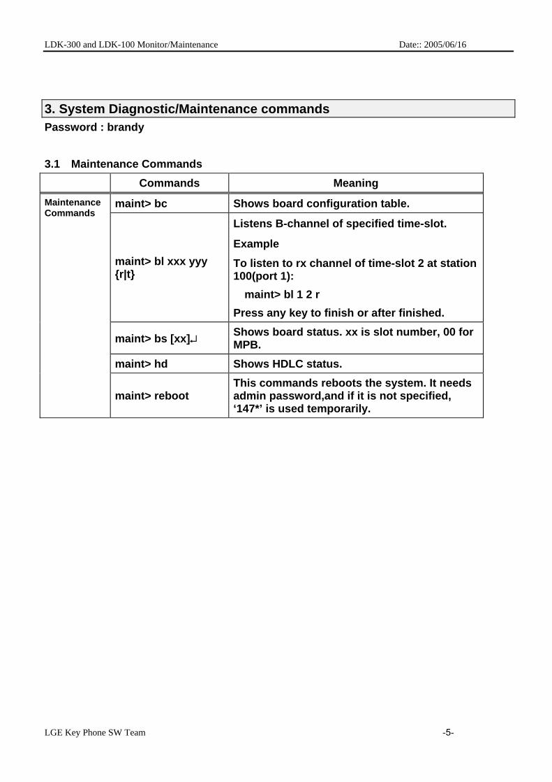
3. System Diagnostic/Maintenance commands Password : brandy
3.1 Maintenance Commands Commands Meaning
maint> bc Shows board configuration table.
maint> bl xxx yyy {r|t}
Listens B-channel of specified time-slot.
Example
To listen to rx channel of time-slot 2 at station 100(port 1):
maint> bl 1 2 r
Press any key to finish or after finished.
maint> bs [xx]↵ Shows board status. xx is slot number, 00 for MPB.
maint> hd Shows HDLC status.
Maintenance Commands
maint> reboot This commands reboots the system. It needs admin password,and if it is not specified, ‘147*’ is used temporarily.

LDK-300 and LDK-100 Monitor/Maintenance Date:: 2005/06/16
LGE Key Phone SW Team -6-
maint> ta [options]
Shows traffic analysis data. Command options: all <timetype>: Print All Traffic Report period <hhmm> <timetype>: Print Traffic Report Periodically period_abort: Cancel Periodic Print atd <timetype>: Print Attendant Traffic Report callsum: Print Call Summary Report callhour: Print Call Hourly Report hw <timetype>: Print H/W Usage Summary Report cosum <timetype>: Print CO Traffic Summary Report cohour <cogrp#>: Print CO Traffic Hourly Report
<timetype> can be one of following: tt : Today Total yt : Yesterday Total lh : Last Hour yp : Yesterday Peak tp : Today Peak
maint> ws xx [options]
xx is slot number. Shows WTIB statistics data. Command options: upload: Upload statistics data from WTIB
call: Total number of call & direction of the call
subs: Information per subscripted device
eoc: End of call
cell: Usage of frequency and slot
traf: Show holding time
acce: Access info.(basic/hand-over)
clea: Clear statistics data

LDK-300 and LDK-100 Monitor/Maintenance Date:: 2005/06/16
LGE Key Phone SW Team -7-
3.2 Diagnostic Commands Commands Meaning
maint> db ? Shows help screen about Diagnostic.
maint> db cc
Shows configuration constraints check result. It gives OK if the system configuration meets the maximum board configuration constraints.
maint> db pf Shows preprogrammed faults. It checks if the admin programming configuration is same with the installed boards.
maint> db ts {sl|cf} Shows time slot assignment and conflict status.
maint> db ht xx yy #
Tests PCM hiway using one DKT and one DTMF receiver.The first DKT of the assigned slot is used for the test.
Command options: xx: slot number(DTIB) yy: dtmf duration time(10ms base) #: hiway number
(0-7 for LDK-300, 0-2 for LDK-100) Example To test hiway #1 using DTIB installed at 1st
slot: maint> db ht 01 01 1
maint> db dt
Tests DTMF receiver. This feature tests all DTMF receivers(LDK-300: up to 32 / LDK-600: up to 64) in the system. Only idle DTMF receivers can be tested.
maint> db ct This command tests CPTU. maint> db mt This command tests DRAM module installed.
maint> db rt Tests RTC. You can see current time and modify it. The time does not elapse while you are testing RTC.
maint> db pc Shows power capacity of the PSU and current power usage status of the system.
maint> db rc Shows RGU capacity. This feature shows RGU capacity, CO incoming ring cadence and ICM call ring cadence.
Diagnostic Commands
maint> de hs Shows HDLC status.

LDK-300 and LDK-100 Monitor/Maintenance Date:: 2005/06/16
LGE Key Phone SW Team -8-
maint> dr {is|ic}
Shows ISDN line status information.
Command options:
is: Shows ISDN line information.
ic: Clears ISDN line information.
maint> dr {ri|rc}
Shows reset information.
Command options:
ri: Shows reset information.
rc: Clears reset information.
maint> dr li {d|c|v|a}
Shows current resource assignment. Command options: d: DTMF receiver assignment c: CPTU assignment v: VMIB channel assignment a: DTMF, CPTU, VMIB channel assignment

LDK-300 and LDK-100 Monitor/Maintenance Date:: 2005/06/16
LGE Key Phone SW Team -9-
This is Help Screen of Diagnostic Commands.

LDK-300 and LDK-100 Monitor/Maintenance Date:: 2005/06/16
LGE Key Phone SW Team -1-
4.Enhanced Trace Guide(Graphical Trace Mode)
4.1 Profile of Enhanced Trace Enhanced Trace is a graphical trace mode of IP-LDK V3.5. This new feature supports the networking message trace of PRI / VOI / BRI / STI (t-mode) / DCO / LCO / NBRI / NPRI Boards. Enhanced Trace is composed of translated messages of digital and analog lines. In case of digital line, networking messages are analyzed by the standard ETSI/ITU protocol and analyzed data is printed with large arrows. In case of analog line, communicated commands with other systems are analyzed and analyzed data is printed with small arrows. Below picture is example of Enhanced Trace.
Digital CO line Trace (with large arrows) Analog CO line Trace (with small arrows) Toward right arrows mean the outgoing message. Otherwise toward left arrows mean the incoming message (Example) Digital CO case * Enhanced Trace must need the DRAM. And It is executed over IP-LDK V3.5
This is outgoing network message for SETUP with CO line 1 (Digital line)
& This message compounds the
information elements of bearer capability,

LDK-300 and LDK-100 Monitor/Maintenance Date:: 2005/06/16
LGE Key Phone SW Team -1-
4.2 Usage of Enhanced Trace Enhanced Trace is one of system monitoring commands. Board Trace: t b x n (‘x’ means board number) All of Networking Trace: t nct (‘nct’ means the set all of networking CO graphical trace) Specific CO Trace: t n c# (option ‘n’ could be used with other options (e, h, c, t) ) * Board Trace & All of Networking Trace: Simple Display Type * Specific CO Trace: Complete Display Type => Simple Display Type shows the Networking Connection Message and Information Elements, but all of
Information Elements (IE) could not be analyzed. Only including data of Called IP, Calling Number, Called Number and Cause elements could be analyzed, and then these data is printed.
=> Complete Display Type shows the Networking Connection Message, Information Elements and all of data contained on Information Elements (IE) data.
4.3 Supported Messages of Enhanced Trace
4.3.1 Digital Line (PRI, VOI, BRI, STI-t, NPRI, NBRI) Type In case of digital line, networking messages are analyzed by the standard ETSI/ITU protocol.
Enhanced Trace Supported Messages for Networking Connection Call Establishment Message Call Information Phase Messages
ALERTING CALL PROCEEDING CONNECT CONNECT ACK PROGRESS SETUP SETUP ACK
USER INFORMATION
Call Clearing Messages Miscellaneous Messages DISCONNECT RELEASE RELEASE COMPLETE
FACILITY INFORMATION STATUS STATUS REQ
* Additional Messages on ISDN also could be supported. Enhanced Trace Supported Message for Information Elements
Networking Information Element
Decoded & Print / Only Print
Networking Information Element
Decoded & Print / Only Print
IE_BEARER_CAPABILITY Decoded & Print
IE_CONNECTED_NO Decoded & Print
IE_CAUSE Decoded & Print
IE_CONNECTED_SUBADDR Only Print Data
IE_CALL_IDENTITY Only Print Data
IE_CALLING_NO Decoded & Print
IE_CALL_STATUS Decoded & Print
IE_CALLING_SUBADDR Only Print Data
IE_CHANNEL_INFO Decoded & Print
IE_CALLED_NO Decoded & Print

LDK-300 and LDK-100 Monitor/Maintenance Date:: 2005/06/16
LGE Key Phone SW Team -2-
IE_AOC Only Print Data
IE_CALLED_SUBADDR Only Print Data
IE_FACILITY Only Print Data
IE_TRANS_NET_SELECT Decoded & Print
IE_PROG_INDICATION Decoded & Print
IE_LOW_LAYER_COMPATIBLE Only Print Data
IE_NET_SPECIFIC_FACILITY Only Print Data
IE_HIGH_LAYER_COMPATIBLE Only Print Data
IE_NOTIFY_INDICATION Decoded & Print
IE_USER_USER Only Print Data
IE_DISPLAY Only Print Data
IE_CONGEST Decoded & Print
IE_DATE_TIME Decoded & Print
IE_ISDN_FLASH_REQ Only Print Data
IE_KEYPAD_FACILITY Only Print Data
IE_ISDN_FLASH_ACK Only Print Data
IE_CALLING_IP Decoded & Print
IE_CALLED_IP Decoded & Print
*Blue Mark: able to decode IE & print the analyzed results. And the others is printed raw (HEX Value) data.
4.3.2 Analog Line Type (DCO, LCO) Type In this case Enhanced Trace could show the related CO commands to communicate with other systems. Analog messages dose not include any information elements, so Enhanced Trace show only the sent or received digit. DCO case
Supported Messages Receive Message Part Send Message Part
Message Type When the Msg is appeared
Message Type When the Msg is appeared
RING DETECT Receive The Call SEIZE Try to Seize the CO Line RING STOP RLS CO Release METERING Detect Call Metering
Signal ANSWER Answer the Call
LOOP IDLE DGT SENT Digit Sent DGT SENT ACK SND REGISTER RCL SEIZE ACK Receive CO Seize ACK SND READY SEIZE NAK SND END OF DIAL RLS ACK Receive CO Release
ACK SND END OF DIAL BUSY
RCV DGT Receive Digit MAKE IDLE RCV ANS Receive Answer Signal SND BLOCKING RCV BLOCK ANI DGT OP Send Another Digit RCV END OF DIAL CALLER ID Receive Caller ID R2 END OF SIGNAL ANI SVC START Detect Another Service
Start
ANI DGT SENT

LDK-300 and LDK-100 Monitor/Maintenance Date:: 2005/06/16
LGE Key Phone SW Team -3-
*Blue Mark: Able to see the related digit. LCO case
Supported Messages Receive Message Part Send Message Part
Message Type When the Msg is appeared
Message Type When the Msg is appeared
RING START Receive The Call SEIZE Try to Seize the CO Line RING STOP RELEASE CO Release CALL METERING Detect Call Metering
Signal ANSWER Answer the Call
LOOP SUP DETECT SEND_DIGIT Digit Sent DIAL TX ACK SEIZE ACK Receive CO Seize ACK SEIZE NAK RELEASE ACK Receive CO Release
ACK
FLASH ACK DISA DGT TONE DETECTED Detect the Tone RELEASED CID DETECT Receive Caller ID
*Blue Mark: Able to see the related digit.

LDK-300 and LDK-100 Monitor/Maintenance Date:: 2005/06/16
LGE Key Phone SW Team -4-
4.4 Enhanced Trace Examples
4.4.1 Incoming Call with PRIB. (ISDN Call)
CO 1 Enhanced Device Trace Complete Display Type
Receive the SETUP networking message with bearer cap, channel, calling number of Information Elements
Printed IE Data
Send the SETUP_ACK networking message with channel, prog_indicator of Information Elements
Calling Number ‘4501000’
Printed IE Data
Printed IE Data

LDK-300 and LDK-100 Monitor/Maintenance Date:: 2005/06/16
LGE Key Phone SW Team -5-
Receive the INFORMATION networking message with called number ‘3’
Receive the INFORMATION networking message with called number ‘0’
Receive the INFORMATION networking message with called number ‘0’
Receive the INFORMATION networking message with called number ‘1’
Send the PROCEEDING networking message

LDK-300 and LDK-100 Monitor/Maintenance Date:: 2005/06/16
LGE Key Phone SW Team -6-
Send the ALRTING networking message
Send the CONNECT networking message with ‘3001’ connected number
Receive the CONNECT ACK networking message
Receive the DISCONNECT networking message with ‘normal call clearing’ message
Send the RELEASE networking message
Receive the RELEASE Complete networking message
LDK-300 and LDK-100 Monitor/Maintenance Date:: 2005/06/16
LGE Key Phone SW Team -1-
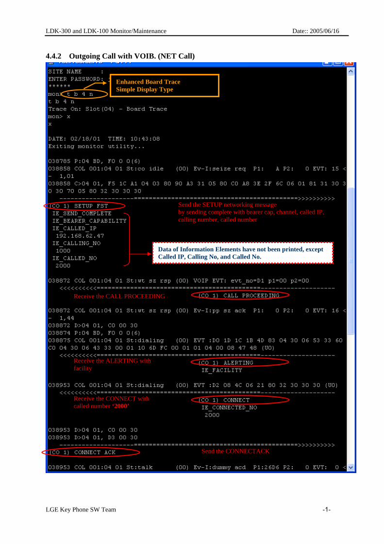
4.4.2 Outgoing Call with VOIB. (NET Call)
Enhanced Board Trace Simple Display Type
Data of Information Elements have not been printed, except Called IP, Calling No, and Called No.
Send the SETUP networking message by sending complete with bearer cap, channel, called IP, calling number, called number
Receive the CALL PROCEEDING
Receive the ALERTING with facility
Receive the CONNECT with called number ‘2000’
Send the CONNECTACK
LDK-300 and LDK-100 Monitor/Maintenance Date:: 2005/06/16
LGE Key Phone SW Team -2-
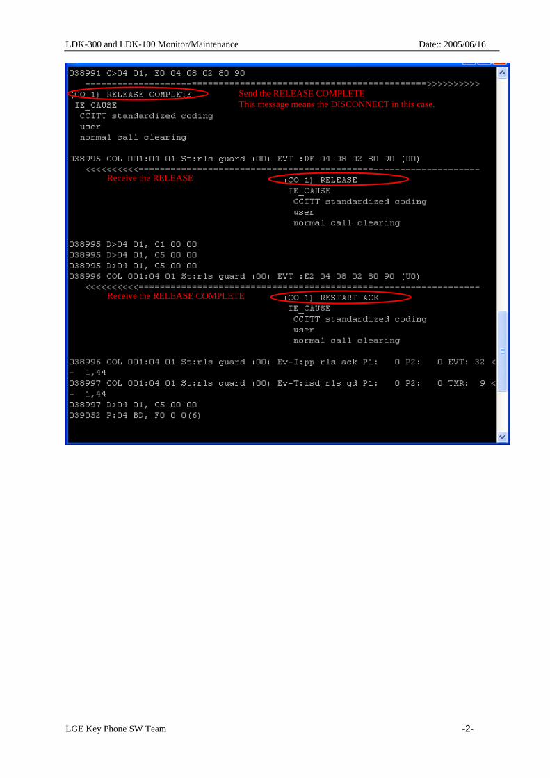
Send the RELEASE COMPLETE This message means the DISCONNECT in this case.
Receive the RELEASE
Receive the RELEASE COMPLETE

LDK-300 and LDK-100 Monitor/Maintenance Date:: 2005/06/16
LGE Key Phone SW Team -3-
4.4.3 Outgoing Call with LCOB. (Analog Call)
Enhanced all of Networking CO Trace Simple Display Type
CO 35 Seize Request Message.
CO 35 Seize ACK Message.
Sending Digit ‘2000’
TALKING CO 35 Release Request
CO 35 Release ACK
Dial Digit ‘2’
Dial Digit ‘0’
Dial Digit ‘0’
Dial Digit ‘0’