LG HVAC SOLUTION · of LG VRF models during the early stage of a project. 02 Model Selection ......
72
LG HVAC SOLUTION
Transcript of LG HVAC SOLUTION · of LG VRF models during the early stage of a project. 02 Model Selection ......

LG HVAC SOLUTION
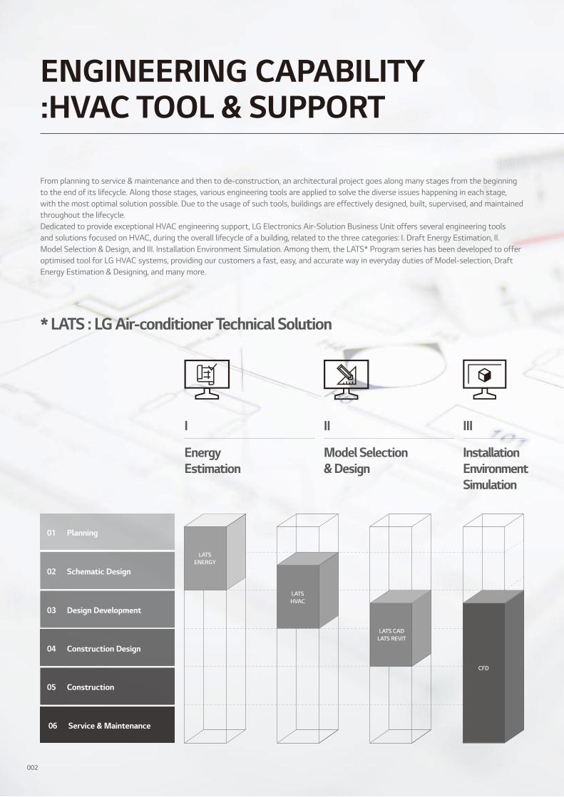
ENGINEERING CAPABILITY :HVAC TOOL & SUPPORT
From planning to service & maintenance and then to de-construction, an architectural project goes along many stages from the beginning to the end of its lifecycle. Along those stages, various engineering tools are applied to solve the diverse issues happening in each stage, with the most optimal solution possible. Due to the usage of such tools, buildings are effectively designed, built, supervised, and maintained throughout the lifecycle.Dedicated to provide exceptional HVAC engineering support, LG Electronics Air-Solution Business Unit offers several engineering tools and solutions focused on HVAC, during the overall lifecycle of a building, related to the three categories: I. Draft Energy Estimation, II. Model Selection & Design, and III. Installation Environment Simulation. Among them, the LATS* Program series has been developed to offer optimised tool for LG HVAC systems, providing our customers a fast, easy, and accurate way in everyday duties of Model-selection, Draft Energy Estimation & Designing, and many more.
* LATS : LG Air-conditioner Technical Solution
II
Model Selection & Design
I
Energy Estimation
III
InstallationEnvironment Simulation
LATSENERGY
LATSHVAC
LATS CADLATS REVIT
CFD
Planning01
Schematic Design02
Construction Design04
Design Development03
Construction05
Service & Maintenance06
002

01 Draft Energy EstimationLATS EnergyLATS Energy program is a draft energy estimation program, self-developed by LG. This program helps estimate the draft energy usage and analyses the life cycle cost of LG VRF models during the early stage of a project.
02 Model SelectionLATS HVACLATS HVAC is an integrated model selection program of LG HVAC products, enabling an accurate and quick selection on the best model suitable to each sites. In addition to model selection, faster estimation on refrigerant piping diameter and additional refrigerant is possible, along with auto printing of reports.
04 Installation Environment SimulationCFD AnalysisCFD Analysis is applied in areas of estimating: indoor airflow and temperature distribution while operating VRF products, outdoor airflow distribution, and noise level. By running a simulation before construction, engineers estimate possible issues and find optimal solutions of malfunction that could occur after construction.
03 DesignLATS CADLATS CAD enables faster and a more accurate design of LG HVAC products. Moreover, it offers not only designing, but also quotation and installation review in order to minimise problems during installation processes.
LATS RevitLATS REVIT is developed to make 3D designing of LG HVAC products easier than the previous program. It enables engineers to check 3D images from designing stage and prevents possible issues of the installation stage.
003

HOTEL
Hotel Room Solution
APARTMENT
Power Distribution Solution
54kW
36kW
24kW
Integration Solution
LG CONTROL SOLUTION
*2016 AC Manager 5004
SMALL BUILDING
Small Central Control Solution
RESIDENTIAL
Smart Individual Control Solution
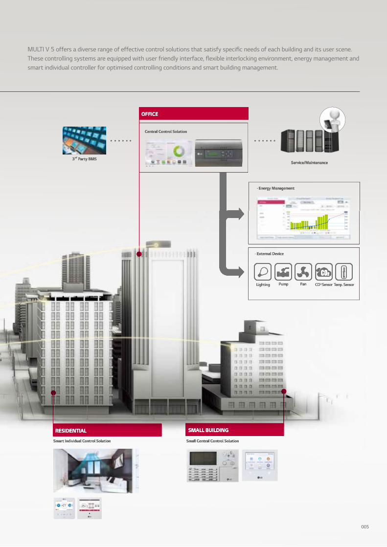
· External Device
Lighting Pump Fan Temp. SensorCO2 Sensor
· Energy Management
3rd Party BMSService/Maintenance
OFFICE
Central Control Solution
· Energy Management
3rd Party BMSService/Maintenance
OFFICE
Central Control Solution
SMALL BUILDING
Small Central Control Solution
RESIDENTIAL RESIDENTIAL
Smart Individual Control Solution
· External Device
Lighting Pump Fan Temp. SensorCO2 Sensor
MULTI V 5 offers a diverse range of effective control solutions that satisfy specific needs of each building and its user scene. These controlling systems are equipped with user friendly interface, flexible interlocking environment, energy management and smart individual controller for optimised controlling conditions and smart building management.
005

BRAND HISTORY
From the moment when LG introduced Korea’s first residential air conditioner in 1968, the company has continuously enhanced its technological innovation and credibility. As a result of sustained improvement, LG VRF launched the first generation of MULTI V in 2006 and achieved significant development. With top class compressor and innovative technology competency applied on every part, cycle and controlling solutions, it has evolved to be one of the world’s most efficient and reliable VRFs.
Following the first and second generations with Inverter technology and non-ozone depleting refrigerant, MULTI V III has advanced its efficiency with diverse cutting-edge technologies such as HiPORTM that directly returns oil to compressor and Vapor Injection that allows double compression by adding mid-pressure refrigerant. As acknowledged by the Eurovent Certification, the innovative technologies of 4th generation secured MULTI V brand the product leadership based on efficient system like Smart Load Control that controls operational load according to external temperature and other technologies that are optimised to manage refrigerant and heat exchange for all cooling, heating and part load operations.
Finally, the time has arrived for LG’s ultimate VRF system, MULTI V 5. This generation has fully improved its technological potential with the powerful, reliable and economical LG’s Ultimate Inverter Compressor, Ocean Black Fin with effective corrosion resistance performance and biomimetics technology-applied to the fan design. At the same time, the Dual Sensing Control offers users a more pleasant environment while minimising the unnecessary energy loss with a system that senses both the temperature and humidity to efficiently manage cooling, heating and part load operations.
The MULTI V 5 that has been solely designed for high efficiency, performance, flexibility, comfort and control.
006

2006
· Ø7.0 Corrugate· Fuzzy Algorithm· AC Inverter· R410A
2008
· Heat Recovery· Ø7.0 Wide louver· Fuzzy Algorithm· LGDC Inverter
2013
· Eurovent Certification· Active Refrigerant Control· Variable Heat Exchanger Circuit· Smart Load Control· Smart Oil Return· Vapor Injection (Advanced)
2010
· High Pressure Oil Return· Vapor Injection· Continuous Heating
· Dual Sensing Control· LG’s Ultimate Inverter Compressor· Large Capacity ODU with Biomimetics Technology Fan
· Continuous Heating· Ocean Black Fin
007
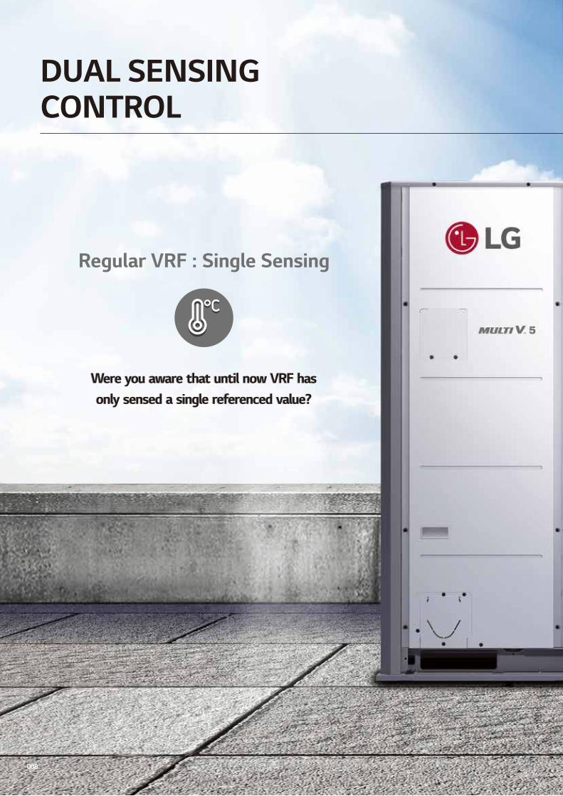
Regular VRF : Single Sensing
Were you aware that until now VRF has only sensed a single referenced value?
Were you aware that until now VRF has only sensed a single referenced value?
DUAL SENSINGCONTROL
008
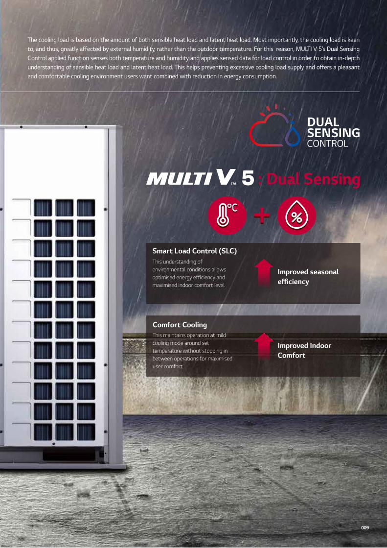
: Dual Sensing
Smart Load Control (SLC)This understanding of environmental conditions allows optimised energy efficiency and maximised indoor comfort level.
Comfort Cooling This maintains operation at mild cooling mode around set temperature without stopping in between operations for maximised user comfort.
Improved IndoorComfort
Improved seasonal efficiency
The cooling load is based on the amount of both sensible heat load and latent heat load. Most importantly, the cooling load is keen to, and thus, greatly affected by external humidity, rather than the outdoor temperature. For this reason, MULTI V 5’s Dual Sensing Control applied function senses both temperature and humidity and applies sensed data for load control in order to obtain in-depth understanding of sensible heat load and latent heat load. This helps preventing excessive cooling load supply and offers a pleasant and comfortable cooling environment users want combined with reduction in energy consumption.
009

04. HiPORTM (High Pressure Oil Return)Resolve compressor efficiency loss caused by oil return
01. Vapor InjectionMaximise heating capacity via two-stage compression
02. Enhanced Bearing with PEEK Material Applied newly invented scroll system driven by PEEK(Polyetheretherketone) bearing used for aero engine• Can operate longer without oil supply• Increase durability and reliability
03. Wide Operation Range from 10 to 165HzImproved part load efficiency at all operation ranges• 10% increase of magnetic flux density
All InverterProvide high efficiency with low vibration and low noise
05. Smart Oil ManagementOil level detection in real time
Six By-pass ValvesPrevent compressor damage due to excessivelycompressed refrigerant more efficiently than 4 by-pass valves
010
LG’s ULTIMATE INVERTERCOMPRESSOR
As the core technology of the air conditioning system, LG’s Ultimate Inverter Compressor of MULTI V 5 boasts a strong efficient and durable design based on the latest technology and innovation of LG HVAC.

011
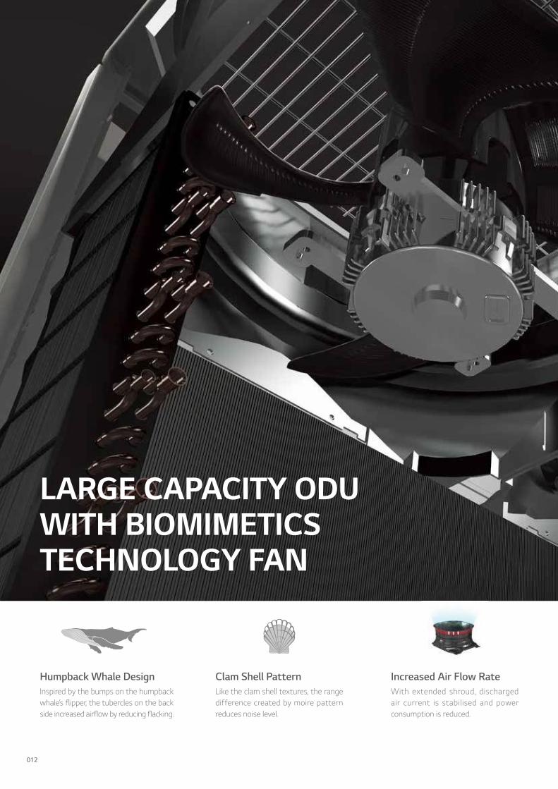
LARGE CAPACITY ODUWITH BIOMIMETICSTECHNOLOGY FAN
Humpback Whale Design Inspired by the bumps on the humpback whale’s flipper, the tubercles on the back side increased airflow by reducing flacking.
Clam Shell Pattern Like the clam shell textures, the range difference created by moire pattern reduces noise level.
Increased Air Flow RateWith extended shroud, discharged air current is stabilised and power consumption is reduced.
012

As a result of the biomimetics technology invented through years of joint study with Department of Mechanical and Aerospace Engineering of Seoul National University, the fan of MULTI V 5 increased airflow capacity while it reduced its power consumption when operating.
Enhanced core parts like biomimetics technology-based fans, 4-sided heat exchanger as opposed to 3-sided heat exchanger of previous model and compressor with increased efficiency and capacity allow large capacity for outdoor units. A single unit of MULTI V 5 can provide up to 72.8kW.
Large Capacity Outdoor Unit
*Based on 4833l/s
013

Improved technologies such as Dual Sensing Control, Partial Defrost and Smart Oil Management enhance Continuous Heating for increased heating capacity and indoor comfort. The delayed and partial defrost technologies minimise unnecessary operational consumption to provide consistent heating.
Down to 7%Power Input
Up to 11%
Heating Operation Time Per Day
Partial Defrost Smart Oil ManagementDual Sensing Control
Non-continuous heating model
CONTINUOUSHEATING
014

The LG exclusive “Ocean Black Fin” heat exchanger is specially designed for durable and long-lasting performance even in corrosive environments. The black coating is applied for protection from various corrosive external conditions and the hydrophilic film keeps water from accumulating on the heat exchanger’s fin, minimising moisture buildup. This improvement in durability prolongs the product’s lifespan and lowers both the operational and maintenance costs.
* Test Method B Simulation Validated( est condition Salt conta inated condition se ere ind strial traffic en iron ent ( 2/SO2)
* Based on 1,500 UL test hours
C E R T I F I C A T E O F V A L I D A T I O N
Certificate Number / Report Reference
4786735320-1 / 4786735320-15-1
Issue Date: 2015-03-25 Expiration Date: 2018-03-24
Issued to: LG Electronics Inc 76 Seongsan-dong, Changwon-Si, Gyeongnam, 641-713, Korea
Claim Validated:
Aluminum Fin & Copper Tube Heat Exchanger employed on the Outdoor Unit of Air-Conditioners. Simulating the corrosive load for 27 years of exposure in a more severe traffic environment with salt contamination(Test Method B).
Tests: Test method B of ISO21207 : Salt contaminated condition + severe industrial or traffic environment
Standards / Regulations: ISO 21207, 6.2 & Annex A LG(65)-E-8148
This certificate and the claim validation expire on the expiration date listed above. UL validated the claim based upon criteria defined by the client. Client’s use of the validated claim on or in connection with the product is and shall remain Client’s representation that the claim is true and accurate. UL neither selected the samples nor determined whether the samples were representative of production units. The test results apply only to the actual samples tested. UL is not responsible for the scope of the tests performed or for the accuracy of test data generated by third parties. Please see test report for full details including test standards.
This certificate in no way conveys or implies Listing, Classification or Recognition or other certification by UL and does not authorize the use of UL Listing, Classification or Recognition Marks on or in connection with the product. The validated claim relates solely to product performance and in no way conveys or implies evaluation of the safety of the product identified above.
Churlbae Kim
Engineering Leader Commercial & Industrial UL Korea Ltd. 26th Fl. Gangnam Finance Center, 737 Yeoksam-dong, Gangnam-gu, Seoul, Korea
OCEAN BLACK FINHEAT EXCHANGER
015
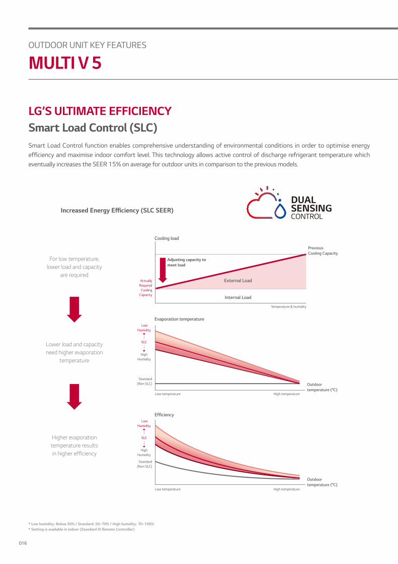
* Low humidity: Below 50% / Standard: 50~70% / High humidity: 70~100%* Setting is available in indoor (Standard III Remote Controller)
Lower load and capacity need higher evaporation
temperature
Outdoor temperature (°C)
Evaporation temperature
Low temperature High temperature
Low Humidity
High Humidity
SLC
Standard (Non SLC)
For low temperature, lower load and capacity
are required
Internal Load
External Load
Previous Cooling Capacity
Temperature & humidity
Cooling load
Adjusting capacity to meet load
Actually Required
Cooling Capacity
Higher evaporation temperature resultsin higher efficiency
Outdoor temperature (°C)
Low temperature High temperature
Standard (Non SLC)
Efficiency Low
Humidity
High Humidity
SLC
ncreased Ener y Efficiency (S C SEER)
LG’S ULTIMATE EFFICIENCYSmart Load Control (SLC)Smart Load Control function enables comprehensive understanding of environmental conditions in order to optimise energy efficiency and maximise indoor comfort level. This technology allows active control of discharge refrigerant temperature which eventually increases the SEER 15% on average for outdoor units in comparison to the previous models.
OUTDOOR UNIT KEY FEATURES
MULTI V 5
016

OUTDDO
R UNIT
HiPOR™ (High Pressure Oil Return)HiPORTM technology enables oil to return directly into the compressor, instead of returning through the refrigerant suction pipe in order to minimise energy losses while maximising the efficiency of compressor. The previous model compressor that caused loss of low pressure refrigerant return to the refrigerant pipe. However MULTI V 5 maximises reliability and efficiency of the compressor by reducing high pressure refrigerant loss.
3
1
2
4
5
Oil
Compressor
Refrigerant
Low pressure refrigerant Oil separator
No energy loss in suction gas
4
High pressure refrigerant
31
Compressor
2
5
RefrigerantOil
Non-HiPOR™
Process comparison
15 20 30 60 90 120 150 (Hz)
Non-HiPORTMEfficiency
Efficiency comparison
* Rating condition (Tc=54.4 °C, Te=7.2 °C)
017

LG’S ULTIMATE EFFICIENCYVapor InjectionVapor Injection uses a two-stage compression effect, which is designed to provide efficient heating in very cold environments. Combined with HiPORTM, this system boosts heating performance and enhances heating temperature range.
Technology mechanismTechnology mechanism
Performance comparison
Outdoor temp.(°C)
Heating performance
-25 -20 -15 -10 -5 0 7 11 15
Non-Vapor Injection
OUTDOOR UNIT KEY FEATURES
MULTI V 5
Low-pressure
High-pressure
Mid-pressure(Vapor injection port)
* Improved heating performance by 27%* Comparison tested on 10HP model
018

OUTDDO
R UNIT
Active Refrigerant ControlActive Refrigerant Control monitors and adjusts the quantity of circulating refrigerant during each cycle to maximise efficiency in real time when it runs cooling and heating operation, as well as the part load operation. This five step control leads to an improvement in energy efficiency, unlike when fixed amount of refrigerant is provided to the compressor regardless of operation mode, which limits optimal efficiency for each operation.
Efficiency performance
Refrigerant quantity (kg)Active Refrigerant Control
Coolingefficiency
Heatingefficiency
Part loadefficiency
Efficiency
Technology mechanism
Fixed refrigerant accumulator
CompressorAccumulator
Receiver
Cooling Heating
Amount of refrigerant in receiver
Part Load
019
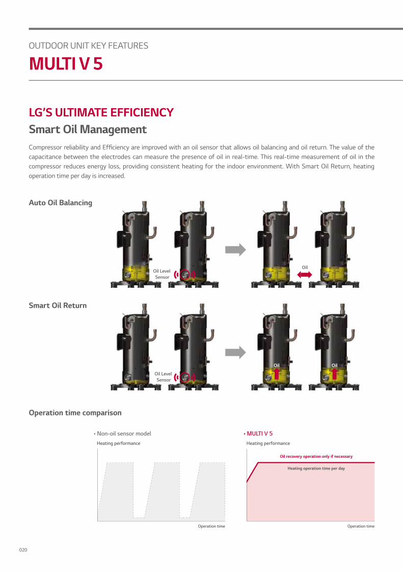
LG’S ULTIMATE EFFICIENCYSmart Oil ManagementCompressor reliability and Efficiency are improved with an oil sensor that allows oil balancing and oil return. The value of the capacitance between the electrodes can measure the presence of oil in real-time. This real-time measurement of oil in the compressor reduces energy loss, providing consistent heating for the indoor environment. With Smart Oil Return, heating operation time per day is increased.
Auto Oil Balancing
Smart Oil Return
Oil Oil
Oil Level Sensor
Oil Level Sensor
OUTDOOR UNIT KEY FEATURES
MULTI V 5
Oil
Operation time
Heating performance
Operation time
Heating performance
Oil recovery operation only if necessary
Heating operation time per day
Operation time comparison
• Non-oil sensor model • MULTI V 5
020

OUTDDO
R UNIT
Variable Heat Exchanger CircuitVariable Heat Exchanger Circuit intelligently selects the optimal path for both heating and cooling operations. With this smart path selection technology, an increase in the efficiency of both operations has been achieved. The paths number and circuit velocity are adjusted to match temperatures and operation modes in order to maximise efficiency instead of compromising efficiency for each operation when the number and direction of paths are fixed independently of temperature operation mode.
Efficiency performance
Number of circuitPrevious Design (Fixed)
Cooling
Heating
Efficiency
Technology mechanism
Fixed heat exchanger circuit
Fixed heat
HeatingCooling
021

LG’S ULTIMATE PERFORMANCE
The LG exclusive Ocean Black Fin is applied on the heat exchanger of MULTI V 5 in order to perform even in corrosive environments. The strong protection from various corrosive external environments such as seaside with high salt contamination and industrial cities with severe air pollution caused by fumes from factories keeps MULTI V 5 operating without breakdown. This improvement in durability prolongs the product’s lifespan and lowers both the operational and maintenance costs.
Heat Exchanger with Ocean Black Fin for Corrosion Resistance
4-sided heat exchanger
3-sided heat exchanger
Previous Model
OUTDOOR UNIT KEY FEATURES
MULTI V 5
022

OUTDDO
R UNIT
Enhanced Coating LayersThe black coating with enhanced epoxy resin is applied for strong protection from various corrosive external conditions such as salt contamination and air pollution including fumes from factories. Moreover, the hydrophilic film keeps water from accumulating on the heat exchanger’s fin, minimising moisture buildup and eventually making it even more corrosion resistant.
Hydrophilic film (Water flow)The Hydrophilic coating minimises moisture buildup on the fin.
Epoxy resin (Corrosion resistant) The Black coating provides strong protection from corrosion.
Aluminum fin
* Test Method B Simulation Validated (Test condition: Salt contaminated condition + se ere ind strial traffic en iron ent( 2/SO2))
* Based on 1,500 UL test hours
R.H. NO2 SO2
95% 10 x 10-5 5 x 10⁻⁶
Condition of gas exposure test
Temperature 35°C
Mist of 5% sodium chloride solution
Condition of salt spray test
Certified protection
Corrosion Resistance Proven by Certified TestsLG Corrosion Resistance solution passed ISO accelerated corrosion test conducted by an independent test organization and the result has been certified by prestigious global certification organisation, UL (Underwriters Laboratories).
023

LG’S ULTIMATE PERFORMANCELarger Capacity ODU with Biomimetics Technology FanThe moire pattern from external texture of clam shells has been applied on fans to create the range difference which results in reduction of noise level. At the same time, unlike the fans installed in previous products that generate separation of flow due to absence of tubercles, the bumpy back design inspired by the bumps on the humpback whale’s flipper is applied as the tubercles on the back side of the fans, increasing airflow by reducing flacking.
OUTDOOR UNIT KEY FEATURES
MULTI V 5
Clam Shell Pattern
Humpback Whale Desigan
Flow difference comparison caused by tubercles
* Biomimetic refers to human-made processes, substances, devices, or systems that imitate nature.
For illustrative purposes only.
Without tubercles
Previous Model
• Previous model
With tubercles
• MULTI V 5
024

OUTDDO
R UNIT
Increased Air Flow Rate with Bigger Shroud
Enhanced Performance with Newly Developed FanBased on the biomimetics technology, the fans of MULTI V 5 increased air flow rate by 10% in comparison to previous model and reduced its power consumption up to 20%. This eventually results in maximised performance with large capacity.
* Comparison based on 56kW model
Previous Model
10%
4833
5333
l/s
ir o rate
* Comparison based on air volume of 4833l/s
Previous Model
20%
1,500
1,200
W
Power consumption
In addition to the biomimetics technology-based fans, extended shroud of MULTI V 5 allows higher static pressure and helps fans to blow higher air volume for efficient operation. With wider air guide, discharged air current is stabilised and noise level is reduced.
025
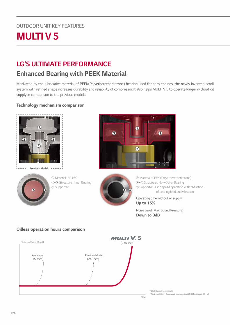
LG’S ULTIMATE PERFORMANCEEnhanced Bearing with PEEK MaterialMotivated by the lubricative material of PEEK(Polyetheretherketone) bearing used for aero engines, the newly invented scroll system with refined shape increases durability and reliability of compressor. It also helps MULTI V 5 to operate longer without oil supply in comparison to the previous models.
Oilless operation hours comparison
Previous Model
2
3 3
1
2
331
Technology mechanism comparison
12
Material : FR160 Structure : Inner BearingSupporter
1 2
Operating time without oil supply Up to 15%
Noise Level (Max. Sound Pressure) Down to 3dB
Material : PEEK (Polyetheretherketone) Structure : New Outer BearingSupporter : High speed operation with reduction
of bearing load and vibration
OUTDOOR UNIT KEY FEATURES
MULTI V 5
Time
Previous Model
Friction coefficient (Defect)
Aluminum
* LG Internal test result * Test condition : Bearing oil blocking test (Oil blocking at 60 Hz)
026

OUTDDO
R UNIT
Reliable Performance in Tough EnvironmentsWith enhanced inverter compressor and control technology coming from improved supercooling technology, vapor injection and Ocean Black Fin, MULTI V 5 extended range of cooling and heating operations. For heating, it can operate at as low as -25°C to perform properly even at very cold environment. MULTI V 5’s cycle technology with enhanced durability enables better cooling performance at high temperature that increases up to 48°C. It is improved to fully function in very tough conditions such as performing cooling operation at -15°C, making the product adequate for uses in specialised venues like technical rooms.
< Cooling >
10°C 14°C
Outdoor air temp.(°C DB)
48°C
43°C
-10°C
-15°C
27°C25°C
Indoor air temp.(°C WB)
Previous Model
Previous Model
* Under the condition of -25°C for outdoor temperature and 20°C for indoor temperature
< Heating >
Outdoor air temp.(°C WB)
18°C
15°C
-20°C
-25°C
10°C 15°C 20°C 27°C
Indoor air temp.(°C DB)
Wider operational range for each performance
027
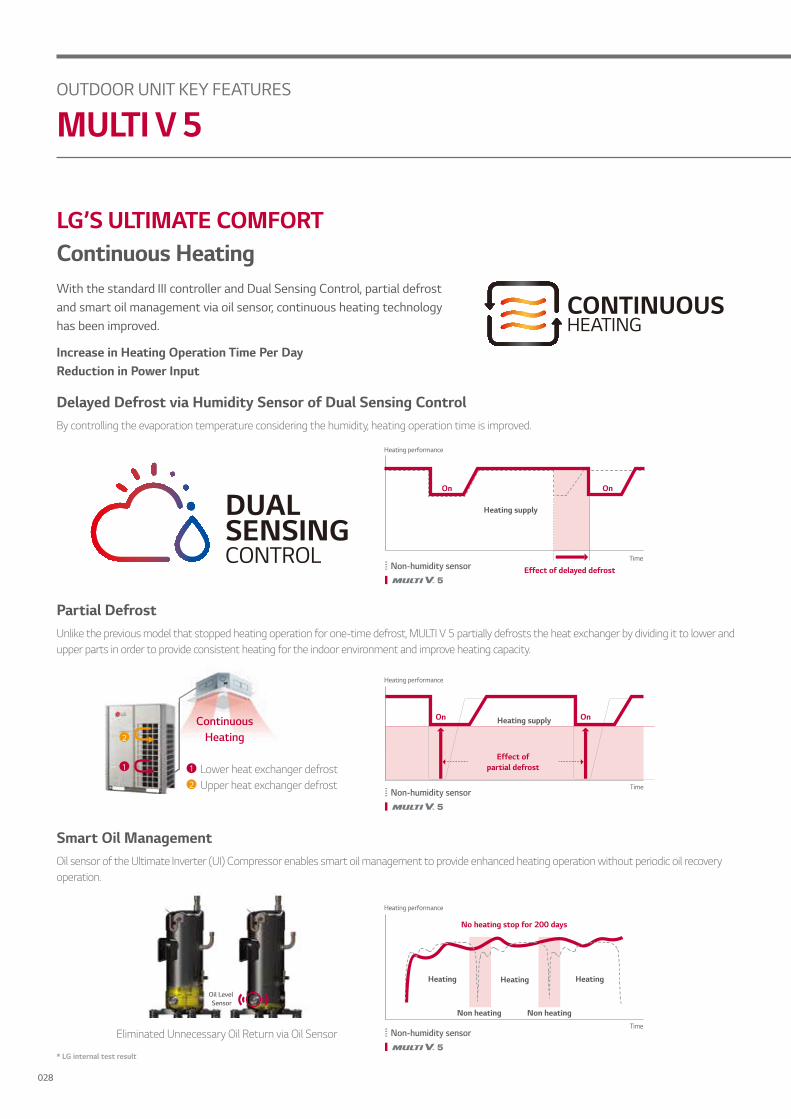
LG’S ULTIMATE COMFORTContinuous HeatingWith the standard III controller and Dual Sensing Control, partial defrost and smart oil management via oil sensor, continuous heating technology has been improved.
Increase in Heating Operation Time Per Day Reduction in Power Input
* LG internal test result
Delayed Defrost via Humidity Sensor of Dual Sensing ControlBy controlling the evaporation temperature considering the humidity, heating operation time is improved.
Smart Oil ManagementOil sensor of the Ultimate Inverter (UI) Compressor enables smart oil management to provide enhanced heating operation without periodic oil recovery operation.
Eliminated Unnecessary Oil Return via Oil Sensor
Oil Level Sensor
OUTDOOR UNIT KEY FEATURES
MULTI V 5
Heating supply
Effect of delayed defrostTime
On On
Non-humidity sensor
Heating performance
Partial DefrostUnlike the previous model that stopped heating operation for one-time defrost, MULTI V 5 partially defrosts the heat exchanger by dividing it to lower and upper parts in order to provide consistent heating for the indoor environment and improve heating capacity.
ContinuousHeating2
1
2
1 Lower heat exchanger defrostUpper heat exchanger defrost
On OnHeating supply
Time
Effect of partial defrost
Heating performance
No heating stop for 200 days
Heating Heating Heating
Non heating Non heatingTime
Heating performance
Non-humidity sensor
Non-humidity sensor
028

OUTDDO
R UNIT
Comfort Cooling Without stopping in between operations, this function allows MULTI V 5 to maintain operation at mild cooling mode around the set temperature by sensing both temperature and humidity with Dual Sensing Control. By preventing both cold draft and repeated turn on/offs previously required to match the set temperature, users can experience more comfortable indoor environment.
Cooling operation comparison
* Indoor unit set up available with Standard III Remote Controller
Previous Model
Cooling Mode Cooling ModeFan Mode
Setting temp.
Toocoolzone
Comfortzone
Notcoolzone
Indoor temp.
Time
Preventing cold draft & repeated turn on/offs Improved indoor comfort
Previous Model
Setting temp.
Toocoolzone
Comfortzone
Notcoolzone
029

LG’S ULTIMATE COMFORTLow-Noise OperationUnlike the previous model which enables Low-Noise Operation only during night after judgment time, the Low-Noise Operation of MULTI V 5 can function regardless of the time at the noise sensitive areas.
Operation hours comparison
Previous Model
OUTDOOR UNIT KEY FEATURES
MULTI V 5
Capacity
Load
Sound level
6:00 13:00 21:00
Highest outdoor temp.
(Judgment time) Low-noise operation time
Start End
6:000:00
On
Off
12:00 18:00
Outdoor setting only
Capacity
Load
Sound level
6:00
Start StartEnd End6:0012:00 18:00
Low-noiseoperation
On
Low-noiseoperation
On
Scheduled setting available
Off
* Indoor unit set up available with Standard III Remote Controller
Indoor setting available
030

OUTDDO
R UNIT
LG’S ULTIMATE FLEXIBILITY MULTI V 5 Outdoor Unit Line Up
* Capacity increase compared to previous model
562822.4kW 84 112 140 168
61.6 ~ 134.422.4*
39.2 ~ 72.8Providing up to 72.8kW for Single Unit
22.4 ~ 33.6Providing up to 33.6kW for Small Size Outdoor Unit
140 ~ 16833.6*
15.5*
031

LG’S ULTIMATE FLEXIBILITYFlexible Installation Space with Large Capacity Outdoor Units Large capacity outdoor units of MULTI V 5 minimises installation space that spares valuable floor space and significantly decreases total installed weights. This allows users the flexible design potential and better use of the saved space.
Previous Model
Comparison on installation space
Comparison basis: 2 Rows of outdoor units 728kW (72.8kW X 10sets) installation case
Installation space Product weight
Previous Model Previous Model
12.25m3
9.42m3 3,100kg
3,640kg
23%Reduction
15%Reduction
Installation space area and product weight comparison
OUTDOOR UNIT KEY FEATURES
MULTI V 5
728kW
728kW
032

OUTDDO
R UNIT
1,000mTotal piping length
Longest piping length
225m Height between ODU ~ IDU
110m
HeightbetweenIDU ~ IDU
40m
Piping length
Total Piping Length 1,000m
Actual longest piping length (Equivalent) 200m (225m)
Longest piping length after 1st branch (conditional application) 40m (90m)
Height between ODU ~ IDU 110m
Height between IDU ~ IDU 40m
Height between ODU ~ ODU 5m
Piping capabilities
Due to improved supercooling circuit and refrigerant controlling technologies, MULTI V 5 allows users to install top class piping lengths, which results in more flexible installation design.
033

LG’S ULTIMATE CONTROLEnergy ManagementEnergy Management allows MULTI V 5 to analyse previous data in order to forecast energy usage beforehand and prevent from exceeding the monthly energy consumption plan by systematically controlling the cooling volume. With energy consulting program that provides automatic operation options for 7 levels of energy management such as compressor capacity management and indoor unit operation level control, users can monitor energy usage anytime and efficiently manage their energy bills.
Management setting example When predicted usage is 120% When the real-time usage is 90%
* Energy Management allows maximum 7 steps (Input format is percent for predicted and real-time usage)* Central control kit such as ACP IV or AC Smart IV and PDI are required for energy management function
Control methods
Compressor capacity management
Saving
Operation rate control of indoor unit Indoor unit operation management
OUTDOOR UNIT KEY FEATURES
MULTI V 5
Energy consumption (kWh)
Predicted usage
Actual usage
Saving energy consumption
Target
5 10 15 20 25 30Day
Management based on monthly predicted usage
1
Management based on real-time usage
2
034

OUTDDO
R UNIT
LG’S ULTIMATE CONTROLSimple Test Run via LGMVIn order to increase performance, a proper product test run is necessary. For previous product, a professional engineer who is well-aware of more than 40 different functional settings and 200+ error codes had to check main parts in order to make sure that the test run had succeeded. With the LGMV smartphone app, a fast and accurate auto test run can be executed and the professional installer running the test can receive test results via email, which shortens installation time and increases overall efficiency in installation processes.
Automatic
LGMV smartphone application setting pages
is feat re is ro ided only to alified rofessional installers **LGMV Application is available for Android and iOS (iphone/ipad)
Wi–Fi MV Module
Previous Model
Manual
Test run comparison
035

HEAT RECOVERY
LG MULTI V 5 satisfies users’ various needs with just one platform. The Heat Pump System works for the sites where either cooling or heating operation is needed, while the Heat Recovery System fits perfectly to the sites wherein both the cooling and heating operations are simultaneously needed or locations installed with Hot Water Solution to provide hot water and heating via radiator. By providing suitable solutions that cater to any building types and their requirements, MULTI V 5 offers LG’s best HVAC system.
Applicable for Various Building Types with Heat Pump & Heat Recovery Systems
Slave 1 Outdoor unit
Liquid Pipe
Liquid Pipe
HR unit
High Pressure Gas Pipe
Low Pressure Gas Pipe
Indoor unit
Master Outdoor unitHeat Pump
System
Slave 1 Outdoor unit
Master Outdoor unit
Liquid Pipe Gas Pipe Indoor unit
Gas Pipe
Liquid Pipe
Heat Recovery System
TypeChangeover
3 pipes
Heat Recovery Unit
2 pipes
Simple Piping System ChangesMULTI V 5 allows the building previously installed with Heat Pump System to switch to the Heat Recovery System for changing purpose of the building or remodeling reasons via simple piping construction.
OUTDOOR UNIT KEY FEATURES
MULTI V 5
036

OUTDDO
R UNIT
HEAT RECOVERYEnergy Saving with Simultaneous OperationMULTI V 5 Heat Recovery system with HR Unit can perform both cooling and heating operations simultaneously. For continuous operation, it minimises in order to switch mode while it increases efficiency with simultaneous operation. Moreover, it allows the COP to reach up to 8.5 under circumstances of 40% cooling and 60% heating operations, which results in significantly decreased energy consumption.
COP with simultaneous operation
* Outdoor temperature : 7°C DB / 6°C WB* Indoor temperature : 20°CDB / 15°C WB * ARMU200LTE5
Operation rate (%)
Heating based operation
0
5
6
7
8
9
20 80 1006040
Maximum8.7
COP
Cooling based operation
4.39 4.59
Technology mechanism
Hydro Kit
Hot water
Indoor cooling
Indoor Unit
Heatemission
Heatabsorption
HR Unit
Heat Recovery
037
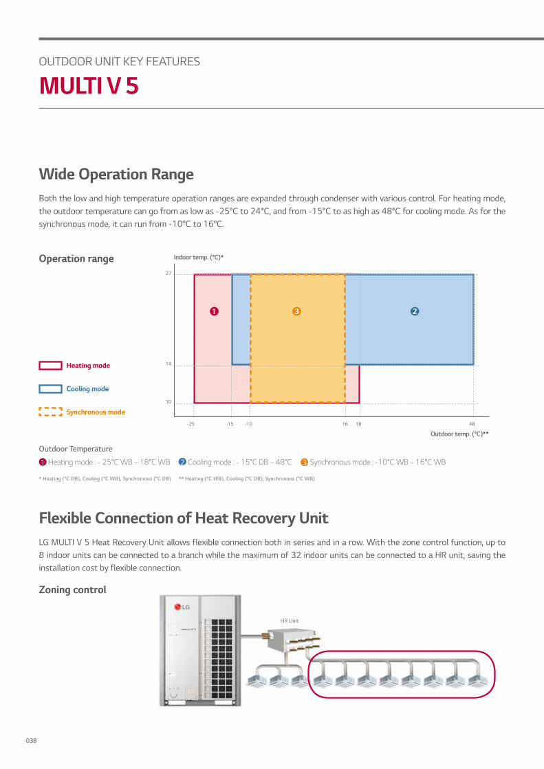
Wide Operation RangeBoth the low and high temperature operation ranges are expanded through condenser with various control. For heating mode, the outdoor temperature can go from as low as -25°C to 24°C, and from -15°C to as high as 48°C for cooling mode. As for the synchronous mode, it can run from -10°C to 16°C.
Flexible Connection of Heat Recovery Unit LG MULTI V 5 Heat Recovery Unit allows flexible connection both in series and in a row. With the zone control function, up to 8 indoor units can be connected to a branch while the maximum of 32 indoor units can be connected to a HR unit, saving the installation cost by flexible connection.
Zoning control
HR Unit
* Heating (°C DB), Cooling (°C WB), Synchronous (°C DB) ** Heating (°C WB), Cooling (°C DB), Synchronous (°C WB)
1 Heating mode : - 25°C WB ~ 18°C WB 2 Cooling mode : - 15°C DB ~ 48°C 3 Synchronous mode : -10°C WB ~ 16°C WB
Outdoor Temperature
Operation range
-25
10
14
27
-15 1816-10
Indoor temp. (°C)*
Outdoor temp. (°C)**
1 3 2
48
Cooling mode
Heating mode
Synchronous mode
OUTDOOR UNIT KEY FEATURES
MULTI V 5
038

OUTDDO
R UNIT
NEW HEAT RECOVERY UNITSummary of New Heat Recovery unit FeaturesExpansion of connectable capacityCompatible with existing LG Heat Recovery unitEasy Serial Connection
Compared to the previous generation Heat Recovery Unit:Improved Service WorkabilityReduce Servicing SpaceReduced NoiseReduce Standby Power
• Connectable capacity per port increased by 25%. (15kW → 17kW)• Total connectable capacity increased by 20%. (60kW → 69.5kW)
Compatible with existing LG Heat Recovery unit
Compared to the previous generation Heat
New Heat Recovery Unit
Expansion of connectable capacity
.
.
.
.
.
.
.
.
New
8 ports
17kW / port
Max 69.5kW
Previous Series
17kW / port
.
.
.
.
.
.
.
.
4 ports
15kW / port
Max 60kW
Maximum number of connectable indoor units : 64 IDUs/HR unit(in case of 8 ports model) Maximum number of connectable indoor units : 32 IDUs/HR unit (in case of 4 ports model)
039

REFRIGERANT PIPING SYSTEMPipe connection method between indoor and outdoor units
Example: 12 Indoor Units connectedOutdoor UnitY branchIndoor UnitsConnection branch pipe between Outdoor units: ARCNB41Connection branch pipe between Outdoor units: ARCNB31Connection branch pipe between Outdoor units: ARCNB21HeaderHR Unit
• Case 1 ("a") : Maximum height is 30m(98.4ft) if you install with Y branch.• Case 2 ("b") : Maximum height is 5m(16.4ft) in serial connection of HR units.
Heat Recovery System: 4 Oudoor Units
WARNING• Branch pipe can not be used after header• It is recommended that difference in length of the pipes connected to the indoor units (a~f) is minimised. The large difference in pipe lengths, the more different performance between indoor units.• * : Serial connection of HR units : Capacity sum of indoor units ≤ 69.5kW. If the large capacity indoor units (Over 14kW; using overØ15.88/Ø9.52) are installed, it should be used the Valve Group setting.• Refer to the HR unit PCB part for the valve group control setting.• Piping length from outdoor branch to outdoor unit ≤ 10m(32.8ft), equivalent length : max 13m(42.7ft). (for 2 units combination or more)
0m o ess
1
2
3
4
A
C1
B
C2C3
a
b
c
d
e
g
j k
l m nsealing
f
i
H
h
"a"
"b"
EF
G
MasterSlave 1
Slave 2
Slave 3
ODU CapacityMaster ≥ Slave1 ≥ Slave 2 ≥ Slave 3
5
6
7
8
109 11 12
ODU CapacityMaster ≥ Slave 1 ≥ Slave 2 ≥ Slave 3
OUTDOOR UNIT KEY FEATURES
MULTI V 5
040

OUTDDO
R UNIT
REFRIGERANT PIPING SYSTEMTotal pipe length = A+B+C1+C2+C3+a+b+c+d+e+f+g+i+j+k+l+m+n ≤ 1,000
Note
Max. pipe length
Total pipe length(A+B+C1+C2+C3+a+b+c+d+e+f+g+i+j+k+l+m+n)
1,000m [3,281ft]
L
Longest pipe length (A+B+C3+k): between Outdoor Unit and Indoor Unit
150m [492ft](200m [656ft]**)
Longest pipe Equivalent length*: between Outdoor Unit and Indoor Unit
175m [574ft](225m [738ft]**)
l Longest pipe length after 1st branch40m [131ft]
(90m [295ft]**)
Max. difference in height
H Between Outdoor Unit and Indoor Unit 110m [361ft]
h Between Indoor Unit and Indoor Unit 40m [131ft]
h1 Between Outdoor Unit and Outdoor Unit 5m [16.4ft]
h2 Between Indoor Unit and HR Unit 15m [49.2ft]
a Between HR Unit and HR Unit 30m [98.4ft]
b Between HR Unit and HR Unit within same branch 5m [16.4ft]
mm (inch)
Ø6.35(1/4)
Ø69.52(3/8)
Ø12.7(1/2)
Ø15.88(5/8)
Ø19.05(3/4)
Ø22.2(7/8)
Ø25.4(1)
Ø28.58(1-1/8)
Ø31.8(1-1/4)
Ø34.9(1-3/8)
Ø28.1(1-1/2)
Ø41.3(1-5/8)
Ø44.5(1-3/4)
Ø53.98(2-1/8)
Elbow (m) 0.16 0.18 0.2 0.25 0.35 0.4 0.45 0.5 0.55 0.6 0.65 0.7 0.75 0.85
Y Branch (m) 0.5
Header (m) 1
HR Unit (m) 2.5
• * : Equivalent piping length for Y Branch and other pipes can be calculated with following table.
• ** : Conditional application.
041

OUTDOOR UNIT KEY FEATURES
MULTI V 5
CONTROLLERSMULTI V 5 offers a diverse range of effective control solutions that satisfy specific needs of each building and its user scene.These controlling systems are equipped with user friendly interface, flexible interlocking environment, energy managementand smart individual controller to help optimise controlling conditions and smart building management.
MULTI V 5 offers a diverse range of effective control solutions that satisfy specific needs of each building and its user scene.
LG’s Control Solution
92kW
20kW
50kW
HOTEL OFFICE RESIDENTIAL APARTMENT SMALL BUILDINGSmall central control
solutionPower distribution
solutionSmart individual control solution
Central control solution
3rd party BMS
Cloud system
Integrated solution
3rd party Cloud
Energy management
External device
Lighting Pump Fan CO2 sensor
Temp sensor
042

OUTDDO
R UNIT
Smart Individual Controller (with Standard III Remote Controller)The new Standard III Remote Controller for MULTI V 5 offers a 4.3-inch large LCD screen with a premium design. This luxurious design well-matches many contemporary interior designs due to its large coloured LCD screen, curved edge display and simple button layout. With diverse information offered such as temperature, humidity and filter information, users can check on currently consumed power in real-time and electricity consumption data(weekly/monthly/annually) to predict and plan power consumption usage. Moreover, the simple and geometrical designed user interface makes it easier to comprehend. With the circular visual theme, the information is labelled in different-sized circles based on their priorities.
Luxurious Design
Intuitive Interface
* Central control kit such as ACP IV or AC Smart IV and PDI are required for energy management function
Energy Management
043

CONTROLLERSEnergy ManagementThe energy navigation function allows MULTI V 5 to preset monthly energy usage and consume only what has been previously planned by analysing and comparing previous consumption and planned energy usage for the month, to help prevent overuse of the HVAC system operational costs.
OUTDOOR UNIT KEY FEATURES
MULTI V 5
Monthly Target Setting
Automatic Control byPower Conumption
Control Step & Logic Selecting(Up to 7 Steps)
Compressor Capacity Control IDU Operation Ratio Control IDU Operation Level
70%
Energy Saving Logic
System Architecture
044

OUTDDO
R UNIT
User Friendly Interface - Flexible DesignAs an advanced central controller, AC Manager 5 offers flexible interface for each user by assessing the device screen and automatically customising the layout to provide a functional and user friendly interface.
11:00 AM 2:00 PM 5:00 PM
PC Tablet MobileMonitoring room Checking each room Working outside
045
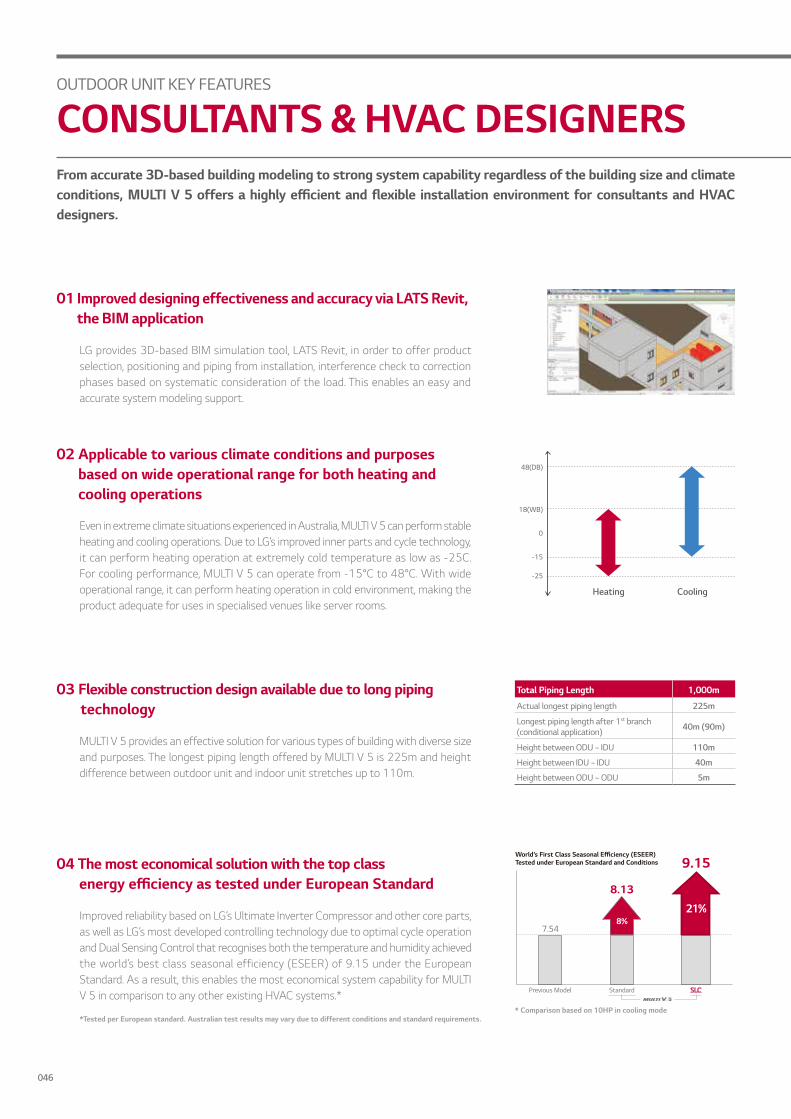
Heating
-25
-15
18(WB)
0
48(DB)
Cooling
Total Piping Length 1,000m
Actual longest piping length 225m
Longest piping length after 1st branch (conditional application) 40m (90m)
Height between ODU ~ IDU 110m
Height between IDU ~ IDU 40m
Height between ODU ~ ODU 5m
* Comparison based on 10HP in cooling mode
From accurate 3D-based building modeling to strong system capability regardless of the building size and climate conditions offers a i ly efficient and e i le installation en iron ent for cons ltants and C designers.
LG provides 3D-based BIM simulation tool, LATS Revit, in order to offer product selection, positioning and piping from installation, interference check to correction phases based on systematic consideration of the load. This enables an easy and accurate system modeling support.
01 Improved designing effectiveness and accuracy via LATS Revit, the BIM application
MULTI V 5 provides an effective solution for various types of building with diverse size and purposes. The longest piping length offered by MULTI V 5 is 225m and height difference between outdoor unit and indoor unit stretches up to 110m.
03 Flexible construction design available due to long piping technology
Improved reliability based on LG’s Ultimate Inverter Compressor and other core parts, as well as LG’s most developed controlling technology due to optimal cycle operation and Dual Sensing Control that recognises both the temperature and humidity achieved the world’s best class seasonal efficiency (ESEER) of 9.15 under the European Standard. As a result, this enables the most economical system capability for MULTI V 5 in comparison to any other existing HVAC systems.*
04 The most economical solution with the top class ener y efficiency as tested nder E ro ean Standard
Even in extreme climate situations experienced in Australia, MULTI V 5 can perform stable heating and cooling operations. Due to LG’s improved inner parts and cycle technology, it can perform heating operation at extremely cold temperature as low as -25C. For cooling performance, MULTI V 5 can operate from -15°C to 48°C. With wide operational range, it can perform heating operation in cold environment, making the product adequate for uses in specialised venues like server rooms.
02 Applicable to various climate conditions and purposes based on wide operational range for both heating and cooling operations
World’s First Class Seasonal Efficiency (ESEER)Tested under European Standard and Conditions
*Tested per European standard. Australian test results may vary due to different conditions and standard requirements.
OUTDOOR UNIT KEY FEATURES
CONSULTANTS & HVAC DESIGNERS
046

OUTDDO
R UNIT
Previous Model
x3768kg
Reduction ofInstallationSpace Area
x2620kg
Due to increased capacity provided by single outdoor units, installation is simpler with a reduced number of o tdoor nits to co ine oreo er sol tions connected to and o erated y s art de ices si nificantly s orten physical hours required for test run, diagnosis and monitoring of multiple services while making these controlling more accurate.
By providing up to 72.8kW for single unit line up, MULTI V 5 decreases the total number of required outdoor units in order to ultimately simplify installation process, when compared to previous models. For example, previous system required a combination of a 56kW outdoor unit, a 50.4kW outdoor unit and a 28kW outdoor unit to run a total of 134.4kW For MULTI V 5, however, only 2 outdoor units with each providing 67.2kW can cover the same amount. This significantly reduces installation hours, especially those that used to take long time such as using crane to properly place outdoor units on the rooftop.
01 Increased installation convenience due to large capacity units reducing number of outdoor units required for combination
With LGMV, the smarter SVC application, hours and resources spent for installation are significantly reduced and more accurate installation and service can be offered.
02 Simple and easy installation and service with Mobile LGMV
Mobile application allows automatic address setting and test run report releasing.
Auto test run
By regularly checking the amount of refrigerant, it automatically reloads if current amount is not enough.
Refrigerant diagnose solution
Unlike before when set up had to be done via DIP Switch of Outdoor unit, installers can simply manage setting via mobile app for MULTI V 5. Indeed, settings for SLC steps, Dual Sensing Control and outdoor unit fan’s maximum RPM control can be easily managed via LGMV.
Easier setting for installers
By checking test run history, black box review and other previous records, site information can be managed efficiently.
Smart management
*LGMV application is available for Android and iOS (iphone/ipad)
OUTDOOR UNIT KEY FEATURES
INSTALLERS
047

Protection certified by UL (Underwriters Laboratories), LG exclusive Ocean Black Fin is applied on the heat exchanger of MULTI V 5 in order to perform even in corrosive environments. The protection from various corrosive external environments such as seaside with high salt contamination and industrial cities with severe air pollution caused by fumes from factories keeps MULTI V 5 operating with high reliability.
01 Corrosion resistance via Ocean Black Fin
With increased reliability of core parts such as compressor and heat exchanger, as well as high operational efficiency ildin o ners can si nificantly red ce o erational costs t t e sa e ti e lar e ca acity o tdoor
nits ini ise installation s ace ic e ent ally allo etter se of t e oor s ace oreo er assists in preventing overuse of the operational costs by planning and consuming the projected monthly energy usage.
MULTI V 5 provides up to 72.8kW for single unit line up. Considering that a total of 218kW is being installed, the total installation space is saved up to 23% while the overall product weight decreases up to 15% in comparison to previous model. This eventually resulted in the maximised use of the saved floor space. Moreover, reduced product weight of MULTI V 5 makes installation easier with less limitation on product weight installed on the building’s rooftop.
02 Minimised installation footprint via large capacity outdoor nits for e i le sa e of t e sa ed oor s ace
· 23% Reduction in Installation Space
· 15% Reduction in Product Weight
Previous Model
MULTI V 5 offers HVAC solution with integrated system that offers both the Heat Pump and the Heat Recovery Systems.Even if the site has been previously installed with Heat Pump System, user can easily replace it with Heat Recovery System or Hot Water Solution when necessary, through simple piping construction which eventually allows more rooms for future remodeling plans.
04 Easy building remodeling with Integral system that offers both the Heat Pump & Heat Recovery
Heat Pump System Heat Recovery System
The energy management function allows MULTI V 5 to preset monthly energy usage and consume what has been previously planned. By analysing and comparing previous consumption and planned energy usage for the month, overuse of the HVAC system operational costs can be prevented.
03 Operational costs management by presetting energy consumption
OUTDOOR UNIT KEY FEATURES
BUILDING OWNERS
048
OUTDDO
R UNIT
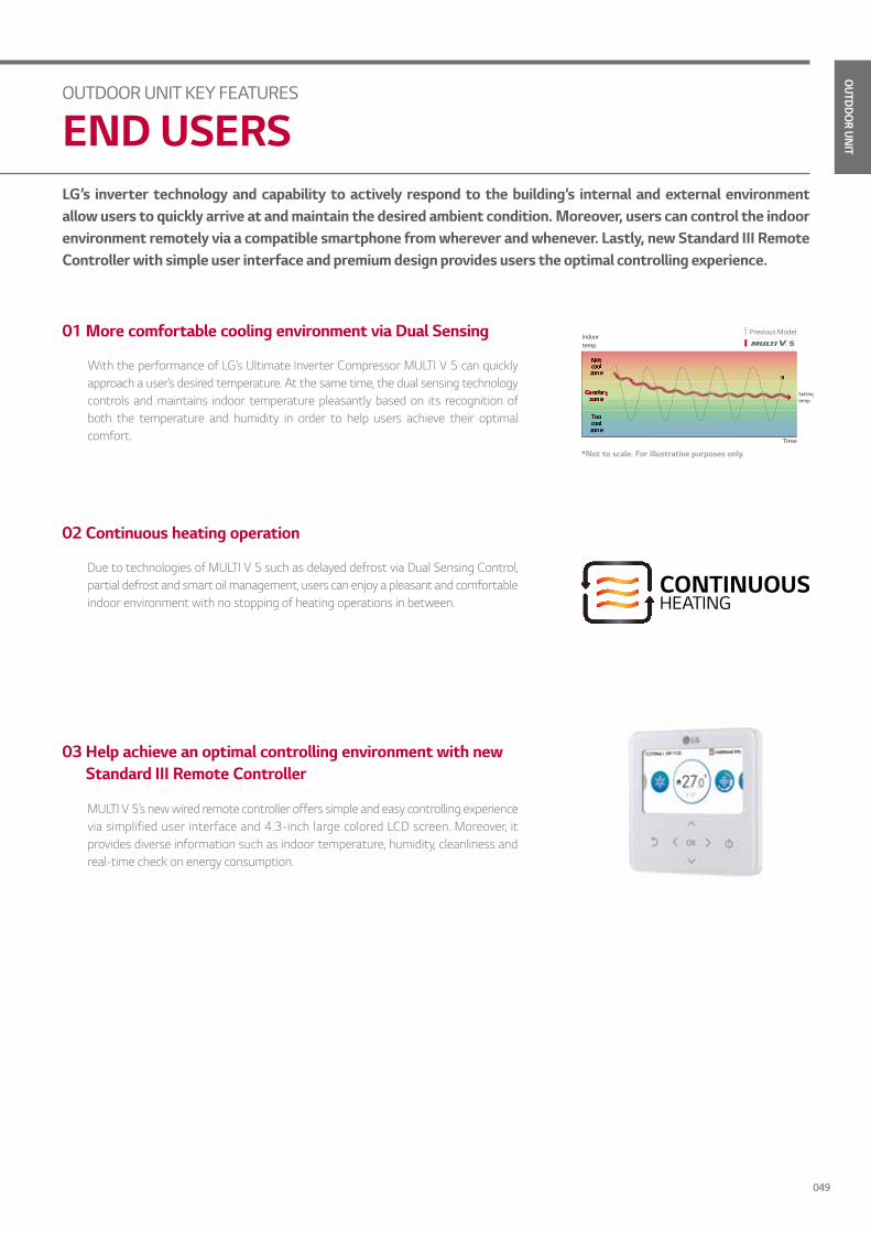
LG’s inverter technology and capability to actively respond to the building’s internal and external environment allow users to quickly arrive at and maintain the desired ambient condition. Moreover, users can control the indoor environment remotely via a compatible smartphone from wherever and whenever. Lastly, new Standard III Remote Controller with simple user interface and premium design provides users the optimal controlling experience.
With the performance of LG’s Ultimate Inverter Compressor MULTI V 5 can quickly approach a user’s desired temperature. At the same time, the dual sensing technology controls and maintains indoor temperature pleasantly based on its recognition of both the temperature and humidity in order to help users achieve their optimal comfort.
01 More comfortable cooling environment via Dual Sensing
Due to technologies of MULTI V 5 such as delayed defrost via Dual Sensing Control, partial defrost and smart oil management, users can enjoy a pleasant and comfortable indoor environment with no stopping of heating operations in between.
02 Continuous heating operation
MULTI V 5’s new wired remote controller offers simple and easy controlling experience via simplified user interface and 4.3-inch large colored LCD screen. Moreover, it provides diverse information such as indoor temperature, humidity, cleanliness and real-time check on energy consumption.
03 Help achieve an optimal controlling environment with new Standard III Remote Controller
OUTDOOR UNIT KEY FEATURES
END USERS
*Not to scale. For illustrative purposes only.
049

OUTDOOR UNIT SPECIFICATION
MULTI V 5ARUM080LTE5/ ARUM100LTE5 / ARUM120LTE5 / ARUM140LTE5 / ARUM160LTE5
Class 8 10 12 14 16
Model NameCombination Unit ARUM080LTE5 ARUM100LTE5 ARUM120LTE5 ARUM140LTE5 ARUM160LTE5
Independent Unit ARUM080LTE5 ARUM100LTE5 ARUM120LTE5 ARUM140LTE5 ARUM160LTE5
Capacity
Cooling (Total)kW 22.4 28.0 33.6 39.2 44.8
Btu/h 76,400 95,500 114,600 133,800 152,900
Cooling (Net/Rated)kW 21.6 27.3 32.5 38.3 44.3
Btu/h 73,700 93,200 110,900 130,700 151,200
Heating (Total)kW 25.2 31.5 37.8 44.1 50.4
Btu/h 86,000 107,500 129,000 150,500 172,000
Heating (Net/Rated)kW 22.0 27.6 33.3 38.0 43.3
Btu/h 75,100 94,200 113,600 129,700 147,700
InputCooling (Total) kW 4.49 5.80 7.58 8.68 10.89
Heating (Total) kW 4.78 5.92 8.26 9.72 12.39
EERTotal 4.99 4.83 4.43 4.52 4.11
Net 4.19 4.01 3.90 3.80 3.33
COPTotal 5.27 5.32 4.58 4.54 4.07
Net 4.49 4.55 4.16 4.00 3.44
Power Factor Net - 0.93 0.93 0.93 0.93 0.93
Heat Exchanger Wide Louver Plus Wide Louver Plus Wide Louver Plus Wide Louver Plus Wide Louver Plus
ExteriorColour Warm Gray / Dawn Gray Warm Gray / Dawn Gray Warm Gray / Dawn Gray Warm Gray / Dawn Gray Warm Gray / Dawn Gray
RAL Code NL503K / NA507K NL503K / NA507K NL503K / NA507K NL503K / NA507K NL503K / NA507K
Compressor
Type Hermetically Sealed Scroll Hermetically Sealed Scroll Hermetically Sealed Scroll Hermetically Sealed Scroll Hermetically Sealed Scroll
Piston Displacement cm3 / rev 43.8 62.1 62.1 62.1 62.1
Number of Revolution rev / min 3,600 3,600 3,600 3,600 3,600
Motor Output x Number W x No. 4,200 x 1 5,300 x 1 5,300 x 1 5,300 x 1 5,300 x 1
Starting Method Direct On Line Direct On Line Direct On Line Direct On Line Direct On Line
Oil Type FVC68D(PVE) FVC68D(PVE) FVC68D(PVE) FVC68D(PVE) FVC68D(PVE)
Fan
Type Propeller Fan Propeller Fan Propeller Fan Propeller Fan Propeller Fan
Motor Output x Number W x No. 1,200 x 1 1,200 x 1 1,200 x 1 900 x 2 900 x 2
Air Flow Rate (High)m3 / min 240 x 1 240 x 1 240 x 1 320 x 1 320 x 1
ft3 / min 8,476 x 1 8,476 x 1 8,476 x 1 11,301 x 1 11,301 x 1
External Static Pressure (Max, Pa) 80 80 80 80 80
Drive DC Inverter DC Inverter DC Inverter DC Inverter DC Inverter
Discharge Side / Top Top Top Top Top Top
Pipe Connections #1
Liquid Pipe mm (inch) 9.52 (3/8) 9.52 (3/8) 12.7 (1/2) 12.7 (1/2) 12.7 (1/2)
Low pressure gas pipe mm (inch) 19.05 (3/4) 22.2 (7/8) 28.58 (1-1/8) 28.58 (1-1/8) 28.58 (1-1/8)
High pressure gas pipe mm (inch) 15.88 (5/8) 19.05 (3/4) 19.05 (3/4) 22.2 (7/8) 22.2 (7/8)
Pipe Connections #2
Liquid Pipe mm (inch) 9.52 (3/8) 9.52 (3/8) 12.7 (1/2) 12.7 (1/2) 12.7 (1/2)
Gas pipe mm (inch) 19.05 (3/4) 22.2 (7/8) 28.58 (1-1/8) 28.58 (1-1/8) 28.58 (1-1/8)
Dimensions (W x H x D) mm (930 x 1,690 x 760) x 1 (930 x 1,690 x 760) x 1 (930 x 1,690 x 760) x 1 (1,240 x 1,690 x 760) x 1 (1,240 x 1,690 x 760) x 1
Net Weightkg 198 x 1 215 x 1 215 x 1 237 x 1 237 x 1
lbs 437 x 1 474 x 1 474 x 1 522 x 1 522 x 1
Sound Pressure Level
Cooling dB(A) 58.0 58.0 59.0 60.0 60.5
Heating dB(A) 59.0 59.0 60.0 610 61.5
Sound Power Level
Cooling dB(A) 84.0 85.0 86.0 89.0 90.0
Heating dB(A) 87.0 88.0 89.0 93.0 94.0
Protection Devices
High pressure protection -High pressure sensor /High pressure switch
High pressure sensor /High pressure switch
High pressure sensor /High pressure switch
High pressure sensor /High pressure switch
High pressure sensor /High pressure switch
Compressor / Fan -Over-heat protection /
Fan driver overload protectorOver-heat protection /
Fan driver overload protectorOver-heat protection /
Fan driver overload protectorOver-heat protection /
Fan driver overload protectorOver-heat protection /
Fan driver overload protector
Inverter -Over-heat protection /
Over-current protectionOver-heat protection /
Over-current protectionOver-heat protection /
Over-current protectionOver-heat protection /
Over-current protectionOver-heat protection /
Over-current protection
Communication Cable No.×mm2
(VCTF-SB)2C x 1.0 ~ 1.5 2C x 1.0 ~ 1.5 2C x 1.0 ~ 1.5 2C x 1.0 ~ 1.5 2C x 1.0 ~ 1.5
Refrigerant
Refrigerant Name R410A R410A R410A R410A R410A
Precharged Amount in factory kg 7.5 9.5 9.5 13.5 13.5
TCO2eq 15.7 19.8 19.8 28.2 28.2
Control Electronic Expansion Valve Electronic Expansion Valve Electronic Expansion Valve Electronic Expansion Valve Electronic Expansion Valve
Power Supply Ø , V, Hz380~415, 3, 50 380~415, 3, 50 380~415, 3, 50 380~415, 3, 50 380~415, 3, 50
380, 3, 60 380, 3, 60 380, 3, 60 380, 3, 60 380, 3, 60
Number of maxmum connectable indoor units5) 13 (20) 16 (25) 20 (30) 23 (35) 26 (40)
050
OUTDDO
R UNIT
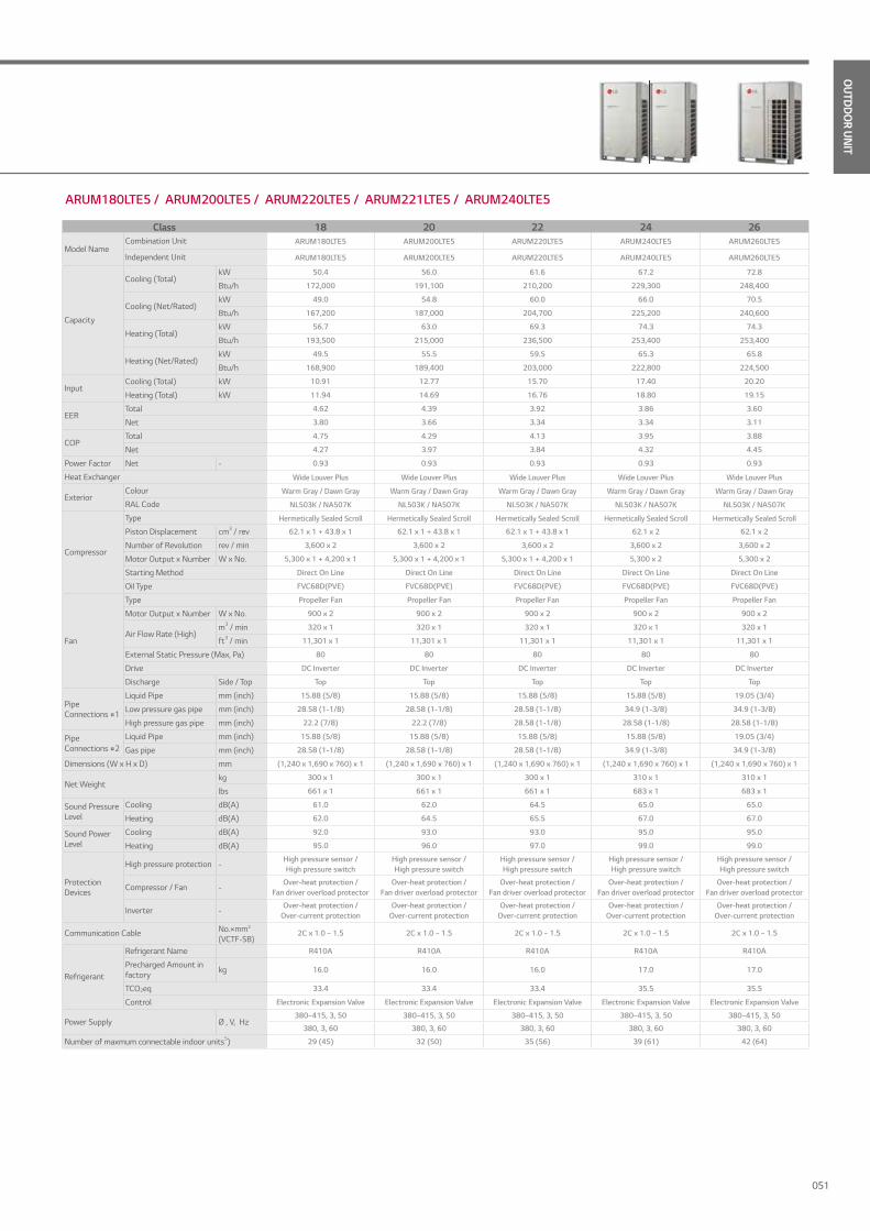
ARUM180LTE5 / ARUM200LTE5 / ARUM220LTE5 / ARUM221LTE5 / ARUM240LTE5
Class 18 20 22 24 26
Model NameCombination Unit ARUM180LTE5 ARUM200LTE5 ARUM220LTE5 ARUM240LTE5 ARUM260LTE5
Independent Unit ARUM180LTE5 ARUM200LTE5 ARUM220LTE5 ARUM240LTE5 ARUM260LTE5
Capacity
Cooling (Total)kW 50.4 56.0 61.6 67.2 72.8
Btu/h 172,000 191,100 210,200 229,300 248,400
Cooling (Net/Rated)kW 49.0 54.8 60.0 66.0 70.5
Btu/h 167,200 187,000 204,700 225,200 240,600
Heating (Total)kW 56.7 63.0 69.3 74.3 74.3
Btu/h 193,500 215,000 236,500 253,400 253,400
Heating (Net/Rated)kW 49.5 55.5 59.5 65.3 65.8
Btu/h 168,900 189,400 203,000 222,800 224,500
InputCooling (Total) kW 10.91 12.77 15.70 17.40 20.20
Heating (Total) kW 11.94 14.69 16.76 18.80 19.15
EERTotal 4.62 4.39 3.92 3.86 3.60
Net 3.80 3.66 3.34 3.34 3.11
COPTotal 4.75 4.29 4.13 3.95 3.88
Net 4.27 3.97 3.84 4.32 4.45
Power Factor Net - 0.93 0.93 0.93 0.93 0.93
Heat Exchanger Wide Louver Plus Wide Louver Plus Wide Louver Plus Wide Louver Plus Wide Louver Plus
ExteriorColour Warm Gray / Dawn Gray Warm Gray / Dawn Gray Warm Gray / Dawn Gray Warm Gray / Dawn Gray Warm Gray / Dawn Gray
RAL Code NL503K / NA507K NL503K / NA507K NL503K / NA507K NL503K / NA507K NL503K / NA507K
Compressor
Type Hermetically Sealed Scroll Hermetically Sealed Scroll Hermetically Sealed Scroll Hermetically Sealed Scroll Hermetically Sealed Scroll
Piston Displacement cm3 / rev 62.1 x 1 + 43.8 x 1 62.1 x 1 + 43.8 x 1 62.1 x 1 + 43.8 x 1 62.1 x 2 62.1 x 2
Number of Revolution rev / min 3,600 x 2 3,600 x 2 3,600 x 2 3,600 x 2 3,600 x 2
Motor Output x Number W x No. 5,300 x 1 + 4,200 x 1 5,300 x 1 + 4,200 x 1 5,300 x 1 + 4,200 x 1 5,300 x 2 5,300 x 2
Starting Method Direct On Line Direct On Line Direct On Line Direct On Line Direct On Line
Oil Type FVC68D(PVE) FVC68D(PVE) FVC68D(PVE) FVC68D(PVE) FVC68D(PVE)
Fan
Type Propeller Fan Propeller Fan Propeller Fan Propeller Fan Propeller Fan
Motor Output x Number W x No. 900 x 2 900 x 2 900 x 2 900 x 2 900 x 2
Air Flow Rate (High)m3 / min 320 x 1 320 x 1 320 x 1 320 x 1 320 x 1
ft3 / min 11,301 x 1 11,301 x 1 11,301 x 1 11,301 x 1 11,301 x 1
External Static Pressure (Max, Pa) 80 80 80 80 80
Drive DC Inverter DC Inverter DC Inverter DC Inverter DC Inverter
Discharge Side / Top Top Top Top Top Top
Pipe Connections #1
Liquid Pipe mm (inch) 15.88 (5/8) 15.88 (5/8) 15.88 (5/8) 15.88 (5/8) 19.05 (3/4)
Low pressure gas pipe mm (inch) 28.58 (1-1/8) 28.58 (1-1/8) 28.58 (1-1/8) 34.9 (1-3/8) 34.9 (1-3/8)
High pressure gas pipe mm (inch) 22.2 (7/8) 22.2 (7/8) 28.58 (1-1/8) 28.58 (1-1/8) 28.58 (1-1/8)
Pipe Connections #2
Liquid Pipe mm (inch) 15.88 (5/8) 15.88 (5/8) 15.88 (5/8) 15.88 (5/8) 19.05 (3/4)
Gas pipe mm (inch) 28.58 (1-1/8) 28.58 (1-1/8) 28.58 (1-1/8) 34.9 (1-3/8) 34.9 (1-3/8)
Dimensions (W x H x D) mm (1,240 x 1,690 x 760) x 1 (1,240 x 1,690 x 760) x 1 (1,240 x 1,690 x 760) x 1 (1,240 x 1,690 x 760) x 1 (1,240 x 1,690 x 760) x 1
Net Weightkg 300 x 1 300 x 1 300 x 1 310 x 1 310 x 1
lbs 661 x 1 661 x 1 661 x 1 683 x 1 683 x 1
Sound Pressure Level
Cooling dB(A) 61.0 62.0 64.5 65.0 65.0
Heating dB(A) 62.0 64.5 65.5 67.0 67.0
Sound Power Level
Cooling dB(A) 92.0 93.0 93.0 95.0 95.0
Heating dB(A) 95.0 96.0 97.0 99.0 99.0
Protection Devices
High pressure protection -High pressure sensor /High pressure switch
High pressure sensor /High pressure switch
High pressure sensor /High pressure switch
High pressure sensor /High pressure switch
High pressure sensor /High pressure switch
Compressor / Fan -Over-heat protection /
Fan driver overload protectorOver-heat protection /
Fan driver overload protectorOver-heat protection /
Fan driver overload protectorOver-heat protection /
Fan driver overload protectorOver-heat protection /
Fan driver overload protector
Inverter -Over-heat protection /
Over-current protectionOver-heat protection /
Over-current protectionOver-heat protection /
Over-current protectionOver-heat protection /
Over-current protectionOver-heat protection /
Over-current protection
Communication Cable No.×mm2
(VCTF-SB)2C x 1.0 ~ 1.5 2C x 1.0 ~ 1.5 2C x 1.0 ~ 1.5 2C x 1.0 ~ 1.5 2C x 1.0 ~ 1.5
Refrigerant
Refrigerant Name R410A R410A R410A R410A R410A
Precharged Amount in factory kg 16.0 16.0 16.0 17.0 17.0
TCO2eq 33.4 33.4 33.4 35.5 35.5
Control Electronic Expansion Valve Electronic Expansion Valve Electronic Expansion Valve Electronic Expansion Valve Electronic Expansion Valve
Power Supply Ø , V, Hz380~415, 3, 50 380~415, 3, 50 380~415, 3, 50 380~415, 3, 50 380~415, 3, 50
380, 3, 60 380, 3, 60 380, 3, 60 380, 3, 60 380, 3, 60
Number of maxmum connectable indoor units5) 29 (45) 32 (50) 35 (56) 39 (61) 42 (64)
051

ARUM221LTE5 / ARUM241LTE5 / ARUM261LTE5 / ARUM280LTE5 / ARUM300LTE5
OUTDOOR UNIT SPECIFICATION
MULTI V 5
Class 22' 24' 26' 28 30
Model Name
Combination Unit ARUM221LTE5 ARUM241LTE5 ARUM261LTE5 ARUM280LTE5 ARUM300LTE5
Independent UnitARUM120LTE5 ARUM120LTE5 ARUM140LTE5 ARUM160LTE5 ARUM180LTE5
ARUM100LTE5 ARUM120LTE5 ARUM120LTE5 ARUM120LTE5 ARUM120LTE5
Capacity
Cooling (Total)kW 61.6 67.2 72.8 78.4 84.0
Btu/h 210,200 229,300 248,400 267,500 286,600
Cooling (Net/Rated)kW 59.8 65.0 70.8 76.8 81.5
Btu/h 204,100 221,800 241,600 262,100 278,100
Heating (Total)kW 69.3 75.6 81.9 88.2 94.5
Btu/h 236,500 257,900 279,400 300,900 322,400
Heating (Net/Rated)kW 60.9 66.6 71.3 76.6 82.8
Btu/h 207,800 227,300 243,300 261,400 282,600
InputCooling (Total) kW 13.38 15.16 16.26 18.47 18.49
Heating (Total) kW 14.18 16.52 17.98 20.65 20.20
EERTotal 4.60 4.43 4.48 4.24 4.54
Net 3.95 3.90 3.85 3.55 3.84
COPTotal 4.89 4.58 4.56 4.27 4.68
Net 4.33 4.16 4.07 3.72 4.22
Power Factor Net - 0.93 0.93 0.93 0.93 0.93
Heat Exchanger Wide Louver Plus Wide Louver Plus Wide Louver Plus Wide Louver Plus Wide Louver Plus
ExteriorColour Warm Gray / Dawn Gray Warm Gray / Dawn Gray Warm Gray / Dawn Gray Warm Gray / Dawn Gray Warm Gray / Dawn Gray
RAL Code NL503K / NA507K NL503K / NA507K NL503K / NA507K NL503K / NA507K NL503K / NA507K
Compressor
Type Hermetically Sealed Scroll Hermetically Sealed Scroll Hermetically Sealed Scroll Hermetically Sealed Scroll Hermetically Sealed Scroll
Piston Displacement cm3 / rev 62.1 x 2 62.1 x 2 62.1 x 2 62.1 x 2 (62.1 x 2) + (43.8 x 1)
Number of Revolution rev / min 3,600 x 2 3,600 x 2 3,600 x 2 3,600 x 2 3,600 x 3
Motor Output x Number W x No. 5,300 x 2 5,300 x 2 5,300 x 2 5,300 x 2 (5,300 x 2) + (4,200 x 1)
Starting Method Direct On Line Direct On Line Direct On Line Direct On Line Direct On Line
Oil Type FVC68D(PVE) FVC68D(PVE) FVC68D(PVE) FVC68D(PVE) FVC68D(PVE)
Fan
Type Propeller Fan Propeller Fan Propeller Fan Propeller Fan Propeller Fan
Motor Output x Number W x No. (1,200 x 1) + (1,200 x 1) (1,200 x 1) + (1,200 x 1) (900 x 1) + (1,200 x 1) (900 x 1) + (1,200 x 1) (900 x 1) + (1,200 x 1)
Air Flow Rate (High)m3 / min (240 x 1) + (240 x 1) (240 x 1) + (240 x 1) (320 x 1) + (240 x 1) (320 x 1) + (240 x 1) (320 x 1) + (240 x 1)
ft3 / min (8,476 x 1) + (8,476 x 1) (8,476 x 1) + (8,476 x 1) (11,301 x 1) + (8,476 x 1) (11,301 x 1) + (8,476 x 1) (11,301 x 1) + (8,476 x 1)
External Static Pressure (Max, Pa) 80 80 80 80 80
Drive DC Inverter DC Inverter DC Inverter DC Inverter DC Inverter
Discharge Side / Top Top Top Top Top Top
Pipe Connections #1
Liquid Pipe mm (inch) 15.88 (5/8) 15.88 (5/8) 19.05 (3/4) 19.05 (3/4) 19.05 (3/4)
Low pressure gas pipe mm (inch) 28.58 (1-1/8) 34.9 (1-3/8) 34.9 (1-3/8) 34.9 (1-3/8) 34.9 (1-3/8)
High pressure gas pipe mm (inch) 28.58 (1-1/8) 28.58 (1-1/8) 28.58 (1-1/8) 28.58 (1-1/8) 28.58 (1-1/8)
Pipe Connections #2
Liquid Pipe mm (inch) 15.88 (5/8) 15.88 (5/8) 19.05 (3/4) 19.05 (3/4) 19.05 (3/4)
Gas pipe mm (inch) 28.58 (1-1/8) 34.9 (1-3/8) 34.9 (1-3/8) 34.9 (1-3/8) 34.9 (1-3/8)
Dimensions (W x H x D) mm(930 x 1,690 x 760) x 1
+ (930 x 1,690 x 760) x 1(930 x 1,690 x 760) x 1
+ (930 x 1,690 x 760) x 1(1,240 x 1,690 x 760) x 1 + (930 x 1,690 x 760) x 1
(1,240 x 1,690 x 760) x 1 + (930 x 1,690 x 760) x 1
(1,240 x 1,690 x 760) x 1 + (930 x 1,690 x 760) x 1
Net Weightkg (215 x 1) + (215 x 1) (215 x 1) + (215 x 1) (237 x 1) + (215 x 1) (237 x 1) + (215 x 1) (300 x 1) + (215 x 1)
lbs (474 x 1) + (474 x 1) (474 x 1) + (474 x 1) (522 x 1) + (474 x 1) (522 x 1) + (474 x 1) (661 x 1) + (474 x 1)
Sound Pressure Level
Cooling dB(A) 61.5 62.0 62.5 62.8 63.1
Heating dB(A) 62.5 63.0 63.5 63.8 64.1
Sound Power Level
Cooling dB(A) 88.5 89.0 90.8 91.5 93.0
Heating dB(A) 91.5 92.0 94.5 95.2 96.0
Protection Devices
High pressure protection -High pressure sensor /High pressure switch
High pressure sensor /High pressure switch
High pressure sensor /High pressure switch
High pressure sensor /High pressure switch
High pressure sensor /High pressure switch
Compressor / Fan -Over-heat protection /
Fan driver overload protectorOver-heat protection /
Fan driver overload protectorOver-heat protection /
Fan driver overload protectorOver-heat protection /
Fan driver overload protectorOver-heat protection /
Fan driver overload protector
Inverter -Over-heat protection /
Over-current protectionOver-heat protection /
Over-current protectionOver-heat protection /
Over-current protectionOver-heat protection /
Over-current protectionOver-heat protection /
Over-current protection
Communication Cable No.×mm2
(VCTF-SB)2C x 1.0 ~ 1.5 2C x 1.0 ~ 1.5 2C x 1.0 ~ 1.5 2C x 1.0 ~ 1.5 2C x 1.0 ~ 1.5
Refrigerant
Refrigerant Name R410A R410A R410A R410A R410A
Precharged Amount in factory kg 19.0 19.0 23.0 23.0 25.5
TCO2eq 39.7 39.7 48.0 48.0 53.2
Control Electronic Expansion Valve Electronic Expansion Valve Electronic Expansion Valve Electronic Expansion Valve Electronic Expansion Valve
Power Supply Ø , V, Hz380~415, 3, 50 380~415, 3, 50 380~415, 3, 50 380~415, 3, 50 380~415, 3, 50
380, 3, 60 380, 3, 60 380, 3, 60 380, 3, 60 380, 3, 60
Number of maxmum connectable indoor units5) 35 (44) 39 (48) 42 (52) 45 (56) 49 (60)
052

OUTDDO
R UNIT
ARUM320LTE5 / ARUM340LTE5 / ARUM360LTE5 / ARUM380LTE5 / ARUM400LTE5
Class 32 34 36 38 40
Model Name
Combination Unit ARUM320LTE5 ARUM340LTE5 ARUM360LTE5 ARUM380LTE5 ARUM400LTE5
Independent UnitARUM200LTE5 ARUM220LTE5 ARUM240LTE5 ARUM240LTE5 ARUM240LTE5
ARUM120LTE5 ARUM120LTE5 ARUM120LTE5 ARUM140LTE5 ARUM160LTE5
Capacity
Cooling (Total)kW 89.6 95.2 100.8 106.4 112.0
Btu/h 305,700 324,800 343,900 363,000 382,100
Cooling (Net/Rated)kW 87.3 92.5 98.5 104.3 110.3
Btu/h 297,900 315,700 336,100 355,900 376,400
Heating (Total)kW 100.8 107.1 112.1 118.4 124.7
Btu/h 343,900 365,400 382,300 403,800 425,300
Heating (Net/Rated)kW 88.8 92.8 98.6 103.3 108.6
Btu/h 303,000 316,700 336,500 352,500 370,600
InputCooling (Total) kW 20.35 23.28 24.98 26.08 28.29
Heating (Total) kW 22.95 25.02 27.06 28.52 31.19
EERTotal 4.40 4.09 4.04 4.08 3.96
Net 3.75 3.52 3.51 3.50 3.33
COPTotal 4.39 4.28 4.14 4.15 4.00
Net 4.04 3.95 4.26 4.20 3.92
Power Factor Net - 0.93 0.93 0.93 0.93 0.93
Heat Exchanger Wide Louver Plus Wide Louver Plus Wide Louver Plus Wide Louver Plus Wide Louver Plus
ExteriorColour Warm Gray / Dawn Gray Warm Gray / Dawn Gray Warm Gray / Dawn Gray Warm Gray / Dawn Gray Warm Gray / Dawn Gray
RAL Code NL503K / NA507K NL503K / NA507K NL503K / NA507K NL503K / NA507K NL503K / NA507K
Compressor
Type Hermetically Sealed Scroll Hermetically Sealed Scroll Hermetically Sealed Scroll Hermetically Sealed Scroll Hermetically Sealed Scroll
Piston Displacement cm3 / rev (62.1 x 2) + (43.8 x 1) (62.1 x 2) + (43.8 x 1) 62.1 x 3 62.1 x 3 62.1 x 3
Number of Revolution rev / min 3,600 x 3 3,600 x 3 3,600 x 3 3,600 x 3 3,600 x 3
Motor Output x Number W x No. (5,300 x 2) + (4,200 x 1) (5,300 x 2) + (4,200 x 1) 5,300 x 3 5,300 x 3 5,300 x 3
Starting Method Direct On Line Direct On Line Direct On Line Direct On Line Direct On Line
Oil Type FVC68D(PVE) FVC68D(PVE) FVC68D(PVE) FVC68D(PVE) FVC68D(PVE)
Fan
Type Propeller Fan Propeller Fan Propeller Fan Propeller Fan Propeller Fan
Motor Output x Number W x No. (900 x 1) + (1,200 x 1) (900 x 1) + (1,200 x 1) (900 x 1) + (1,200 x 1) 900 x 4 900 x 4
Air Flow Rate (High)m3 / min (320 x 1) + (240 x 1) (320 x 1) + (240 x 1) (320 x 1) + (240 x 1) 320 x 2 320 x 2
ft3 / min (11,301 x 1) + (8,476 x 1) (11,301 x 1) + (8,476 x 1) (11,301 x 1) + (8,476 x 1) 11,301 x 2 11,301 x 2
External Static Pressure (Max, Pa) 80 80 80 80 80
Drive DC Inverter DC Inverter DC Inverter DC Inverter DC Inverter
Discharge Side / Top Top Top Top Top Top
Pipe Connections #1
Liquid Pipe mm (inch) 19.05 (3/4) 19.05 (3/4) 19.05 (3/4) 19.05 (3/4) 19.05 (3/4)
Low pressure gas pipe mm (inch) 34.9 (1-3/8) 34.9 (1-3/8) 41.3 (1-5/8) 41.3 (1-5/8) 41.3 (1-5/8)
High pressure gas pipe mm (inch) 28.58 (1-1/8) 28.58 (1-1/8) 28.58 (1-1/8) 28.58 (1-1/8) 28.58 (1-1/8)
Pipe Connections #2
Liquid Pipe mm (inch) 19.05 (3/4) 19.05 (3/4) 19.05 (3/4) 19.05 (3/4) 19.05 (3/4)
Gas pipe mm (inch) 34.9 (1-3/8) 34.9 (1-3/8) 41.3 (1-5/8) 41.3 (1-5/8) 41.3 (1-5/8)
Dimensions (W x H x D) mm(1,240 x 1,690 x 760) x 1 + (930 x 1,690 x 760) x 1
(1,240 x 1,690 x 760) x 1 + (930 x 1,690 x 760) x 1
(1,240 x 1,690 x 760) x 1 + (930 x 1,690 x 760) x 1
(1,240 x 1,690 x 760) x 2 (1,240 x 1,690 x 760) x 2
Net Weightkg (300 x 1) + (215 x 1) (300 x 1) + (215 x 1) (310 x 1) + (215 x 1) (310 x 1) + (215 x 1) (310 x 1) + (215 x 1)
lbs (661 x 1) + (474 x 1) (661 x 1) + (474 x 1) (683 x 1) + (474 x 1) (683 x 1) + (474 x 1) (683 x 1) + (474 x 1)
Sound Pressure Level
Cooling dB(A) 63.8 65.6 66.0 66.2 66.3
Heating dB(A) 65.8 66.6 67.8 68.0 68.1
Sound Power Level
Cooling dB(A) 93.8 93.8 95.5 96.0 96.2
Heating dB(A) 96.8 97.6 99.4 100.0 100.2
Protection Devices
High pressure protection -High pressure sensor /High pressure switch
High pressure sensor /High pressure switch
High pressure sensor /High pressure switch
High pressure sensor /High pressure switch
High pressure sensor /High pressure switch
Compressor / Fan -Over-heat protection /
Fan driver overload protectorOver-heat protection /
Fan driver overload protectorOver-heat protection /
Fan driver overload protectorOver-heat protection /
Fan driver overload protectorOver-heat protection /
Fan driver overload protector
Inverter -Over-heat protection /
Over-current protectionOver-heat protection /
Over-current protectionOver-heat protection /
Over-current protectionOver-heat protection /
Over-current protectionOver-heat protection /
Over-current protection
Communication Cable No.×mm2
(VCTF-SB)2C x 1.0 ~ 1.5 2C x 1.0 ~ 1.5 2C x 1.0 ~ 1.5 2C x 1.0 ~ 1.5 2C x 1.0 ~ 1.5
Refrigerant
Refrigerant Name R410A R410A R410A R410A R410A
Precharged Amount in factory kg 25.5 25.5 26.5 30.5 30.5
TCO2eq 53.2 53.2 55.3 63.7 63.7
Control Electronic Expansion Valve Electronic Expansion Valve Electronic Expansion Valve Electronic Expansion Valve Electronic Expansion Valve
Power Supply Ø , V, Hz380~415, 3, 50 380~415, 3, 50 380~415, 3, 50 380~415, 3, 50 380~415, 3, 50
380, 3, 60 380, 3, 60 380, 3, 60 380, 3, 60 380, 3, 60
Number of maxmum connectable indoor units5) 52 (64) 55 (64) 58 (64) 61 (64) 64
053
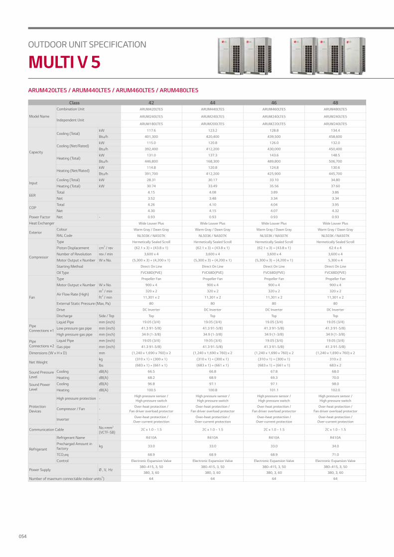
ARUM420LTE5 / ARUM440LTE5 / ARUM460LTE5 / ARUM480LTE5
OUTDOOR UNIT SPECIFICATION
MULTI V 5
Class 42 44 46 48
Model Name
Combination Unit ARUM420LTE5 ARUM440LTE5 ARUM460LTE5 ARUM480LTE5
Independent UnitARUM240LTE5 ARUM240LTE5 ARUM240LTE5 ARUM240LTE5
ARUM180LTE5 ARUM200LTE5 ARUM220LTE5 ARUM240LTE5
Capacity
Cooling (Total)kW 117.6 123.2 128.8 134.4
Btu/h 401,300 420,400 439,500 458,600
Cooling (Net/Rated)kW 115.0 120.8 126.0 132.0
Btu/h 392,400 412,200 430,000 450,400
Heating (Total)kW 131.0 137.3 143.6 148.5
Btu/h 446,800 168,300 489,800 506,700
Heating (Net/Rated)kW 114.8 120.8 124.8 130.6
Btu/h 391,700 412,200 425,900 445,700
InputCooling (Total) kW 28.31 30.17 33.10 34.80
Heating (Total) kW 30.74 33.49 35.56 37.60
EERTotal 4.15 4.08 3.89 3.86
Net 3.52 3.48 3.34 3.34
COPTotal 4.26 4.10 4.04 3.95
Net 4.30 4.15 4.07 4.32
Power Factor Net - 0.93 0.93 0.93 0.93
Heat Exchanger Wide Louver Plus Wide Louver Plus Wide Louver Plus Wide Louver Plus
ExteriorColour Warm Gray / Dawn Gray Warm Gray / Dawn Gray Warm Gray / Dawn Gray Warm Gray / Dawn Gray
RAL Code NL503K / NA507K NL503K / NA507K NL503K / NA507K NL503K / NA507K
Compressor
Type Hermetically Sealed Scroll Hermetically Sealed Scroll Hermetically Sealed Scroll Hermetically Sealed Scroll
Piston Displacement cm3 / rev (62.1 x 3) + (43.8 x 1) (62.1 x 3) + (43.8 x 1) (62.1 x 3) + (43.8 x 1) 62.4 x 4
Number of Revolution rev / min 3,600 x 4 3,600 x 4 3,600 x 4 3,600 x 4
Motor Output x Number W x No. (5,300 x 3) + (4,200 x 1) (5,300 x 3) + (4,200 x 1) (5,300 x 3) + (4,200 x 1) 5,300 x 4
Starting Method Direct On Line Direct On Line Direct On Line Direct On Line
Oil Type FVC68D(PVE) FVC68D(PVE) FVC68D(PVE) FVC68D(PVE)
Fan
Type Propeller Fan Propeller Fan Propeller Fan Propeller Fan
Motor Output x Number W x No. 900 x 4 900 x 4 900 x 4 900 x 4
Air Flow Rate (High)m3 / min 320 x 2 320 x 2 320 x 2 320 x 2
ft3 / min 11,301 x 2 11,301 x 2 11,301 x 2 11,301 x 2
External Static Pressure (Max, Pa) 80 80 80 80
Drive DC Inverter DC Inverter DC Inverter DC Inverter
Discharge Side / Top Top Top Top Top
Pipe Connections #1
Liquid Pipe mm (inch) 19.05 (3/4) 19.05 (3/4) 19.05 (3/4) 19.05 (3/4)
Low pressure gas pipe mm (inch) 41.3 91-5/8) 41.3 91-5/8) 41.3 91-5/8) 41.3 91-5/8)
High pressure gas pipe mm (inch) 34.9 (1-3/8) 34.9 (1-3/8) 34.9 (1-3/8) 34.9 (1-3/8)
Pipe Connections #2
Liquid Pipe mm (inch) 19.05 (3/4) 19.05 (3/4) 19.05 (3/4) 19.05 (3/4)
Gas pipe mm (inch) 41.3 91-5/8) 41.3 91-5/8) 41.3 91-5/8) 41.3 91-5/8)
Dimensions (W x H x D) mm (1,240 x 1,690 x 760) x 2 (1,240 x 1,690 x 760) x 2 (1,240 x 1,690 x 760) x 2 (1,240 x 1,690 x 760) x 2
Net Weightkg (310 x 1) + (300 x 1) (310 x 1) + (300 x 1) (310 x 1) + (300 x 1) 310 x 2
lbs (683 x 1) + (661 x 1) (683 x 1) + (661 x 1) (683 x 1) + (661 x 1) 683 x 2
Sound Pressure Level
Cooling dB(A) 66.5 66.8 67.8 68.0
Heating dB(A) 68.2 68.9 69.3 70.0
Sound Power Level
Cooling dB(A) 96.8 97.1 97.1 98.0
Heating dB(A) 100.5 100.8 101.1 102.0
Protection Devices
High pressure protection -High pressure sensor /High pressure switch
High pressure sensor /High pressure switch
High pressure sensor /High pressure switch
High pressure sensor /High pressure switch
Compressor / Fan -Over-heat protection /
Fan driver overload protectorOver-heat protection /
Fan driver overload protectorOver-heat protection /
Fan driver overload protectorOver-heat protection /
Fan driver overload protector
Inverter -Over-heat protection /
Over-current protectionOver-heat protection /
Over-current protectionOver-heat protection /
Over-current protectionOver-heat protection /
Over-current protection
Communication Cable No.×mm2
(VCTF-SB)2C x 1.0 ~ 1.5 2C x 1.0 ~ 1.5 2C x 1.0 ~ 1.5 2C x 1.0 ~ 1.5
Refrigerant
Refrigerant Name R410A R410A R410A R410A
Precharged Amount in factory kg 33.0 33.0 33.0 34.0
TCO2eq 68.9 68.9 68.9 71.0
Control Electronic Expansion Valve Electronic Expansion Valve Electronic Expansion Valve Electronic Expansion Valve
Power Supply Ø , V, Hz380~415, 3, 50 380~415, 3, 50 380~415, 3, 50 380~415, 3, 50
380, 3, 60 380, 3, 60 380, 3, 60 380, 3, 60
Number of maxmum connectable indoor units5) 64 64 64 64
054
OUTDDO
R UNIT
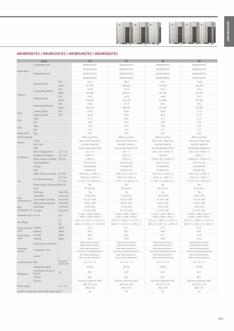
ARUM500LTE5 / ARUM520LTE5 / ARUM540LTE5 / ARUM560LTE5
Class 50 52 54 56
Model Name
Combination Unit ARUM500LTE5 ARUM520LTE5 ARUM540LTE5 ARUM560LTE5
Independent Unit
ARUM240LTE5 ARUM240LTE5 ARUM240LTE5 ARUM240LTE5
ARUM140LTE5 ARUM160LTE5 ARUM180LTE5 ARUM200LTE5
ARUM120LTE5 ARUM120LTE5 ARUM120LTE5 ARUM120LTE5
Capacity
Cooling (Total)kW 140.0 145.6 151.2 156.8
Btu/h 477,700 496,800 515,900 353,000
Cooling (Net/Rated)kW 136.8 142.8 147.5 153.3
Btu/h 466,800 487,300 503,300 523,100
Heating (Total)kW 156.2 162.5 168.8 175.1
Btu/h 532,800 554,300 575,800 597,300
Heating (Net/Rated)kW 136.6 141.9 148.1 154.1
Btu/h 466,100 484,200 505,400 525,800
InputCooling (Total) kW 33.66 35.87 35.89 37.75
Heating (Total) kW 36.78 39.45 39.00 41.75
EERTotal 4.16 4.06 4.21 4.15
Net 3.58 3.45 3.60 3.56
COPTotal 4.25 4.12 4.33 4.19
Net 4.19 3.97 4.27 4.15
Power Factor Net - 0.93 0.93 0.93 0.93
Heat Exchanger Wide Louver Plus Wide Louver Plus Wide Louver Plus Wide Louver Plus
ExteriorColour Warm Gray / Dawn Gray Warm Gray / Dawn Gray Warm Gray / Dawn Gray Warm Gray / Dawn Gray
RAL Code NL503K / NA507K NL503K / NA507K NL503K / NA507K NL503K / NA507K
Compressor
Type Hermetically Sealed Scroll Hermetically Sealed Scroll Hermetically Sealed Scroll Hermetically Sealed Scroll
Piston Displacement cm3 / rev 62.1 x 4 62.1 x 4 (62.1 x 4) + (43.8 x 1) (62.1 x 4) + (43.8 x 1)
Number of Revolution rev / min 3,600 x 4 3,600 x 4 3,600 x 5 3,600 x 5
Motor Output x Number W x No. 5,300 x 4 5,300 x 4 (5,300 x 4) + (4,200 x 1) (5,300 x 4) + (4,200 x 1)
Starting Method Direct On Line Direct On Line Direct On Line Direct On Line
Oil Type FVC68D(PVE) FVC68D(PVE) FVC68D(PVE) FVC68D(PVE)
Fan
Type Propeller Fan Propeller Fan Propeller Fan Propeller Fan
Motor Output x Number W x No. (900 x 4) + (1,200 x 1) (900 x 4) + (1,200 x 1) (900 x 4) + (1,200 x 1) (900 x 4) + (1,200 x 1)
Air Flow Rate (High)m3 / min (320 x 2) + (240 x 1) (320 x 2) + (240 x 1) (320 x 2) + (240 x 1) (320 x 2) + (240 x 1)
ft3 / min (11,301 x 2) + (8,476 x 1) (11,301 x 2) + (8,476 x 1) (11,301 x 2) + (8,476 x 1) (11,301 x 2) + (8,476 x 1)
External Static Pressure (Max, Pa) 80 80 80 80
Drive DC Inverter DC Inverter DC Inverter DC Inverter
Discharge Side / Top Top Top Top Top
Pipe Connections #1
Liquid Pipe mm (inch) 19.05 (3/4) 19.05 (3/4) 19.05 (3/4) 19.05 (3/4)
Low pressure gas pipe mm (inch) 41.3 91-5/8) 41.3 91-5/8) 41.3 91-5/8) 41.3 91-5/8)
High pressure gas pipe mm (inch) 34.9 (1-3/8) 34.9 (1-3/8) 34.9 (1-3/8) 34.9 (1-3/8)
Pipe Connections #2
Liquid Pipe mm (inch) 19.05 (3/4) 19.05 (3/4) 19.05 (3/4) 19.05 (3/4)
Gas pipe mm (inch) 41.3 91-5/8) 41.3 91-5/8) 41.3 91-5/8) 41.3 91-5/8)
Dimensions (W x H x D) mm(1,240 x 1,690 x 760) x 2 + (930 x 1,690 x 760) x 1
(1,240 x 1,690 x 760) x 2 + (930 x 1,690 x 760) x 1
(1,240 x 1,690 x 760) x 2 + (930 x 1,690 x 760) x 1
(1,240 x 1,690 x 760) x 2 + (930 x 1,690 x 760) x 1
Net Weightkg (310 x 1) + (237 x 1) + (215 x 1) (310 x 1) + (237 x 1) + (215 x 1) (310 x 1) + (300 x 1) + (215 x 1) (310 x 1) + (300 x 1) + (215 x 1)
lbs (683 x 1) + (522 x 1) + (474 x 1) (683 x 1) + (522 x 1) + (474 x 1) (683 x 1) + (661 x 1) + (474 x 1) (683 x 1) + (661 x 1) + (474 x 1)
Sound Pressure Level
Cooling dB(A) 67.0 67.1 67.2 67.4
Heating dB(A) 68.6 68.7 68.8 69.5
Sound Power Level
Cooling dB(A) 96.4 96.6 97.1 97.4
Heating dB(A) 100.3 100.5 100.8 101.0
Protection Devices
High pressure protection -High pressure sensor /High pressure switch
High pressure sensor /High pressure switch
High pressure sensor /High pressure switch
High pressure sensor /High pressure switch
Compressor / Fan -Over-heat protection /
Fan driver overload protectorOver-heat protection /
Fan driver overload protectorOver-heat protection /
Fan driver overload protectorOver-heat protection /
Fan driver overload protector
Inverter -Over-heat protection /
Over-current protectionOver-heat protection /
Over-current protectionOver-heat protection /
Over-current protectionOver-heat protection /
Over-current protection
Communication Cable No.×mm2
(VCTF-SB)2C x 1.0 ~ 1.5 2C x 1.0 ~ 1.5 2C x 1.0 ~ 1.5 2C x 1.0 ~ 1.5
Refrigerant
Refrigerant Name R410A R410A R410A R410A
Precharged Amount in factory kg 40.0 40.0 42.5 42.5
TCO2eq 83.5 83.5 88.7 88.7
Control Electronic Expansion Valve Electronic Expansion Valve Electronic Expansion Valve Electronic Expansion Valve
Power Supply Ø , V, Hz380~415, 3, 50 380~415, 3, 50 380~415, 3, 50 380~415, 3, 50
380, 3, 60 380, 3, 60 380, 3, 60 380, 3, 60
Number of maxmum connectable indoor units5) 64 64 64 64
055

ARUM580LTE5 / ARUM600LTE5 / ARUM620LTE5 / ARUM640LTE5
OUTDOOR UNIT SPECIFICATION
MULTI V 5
Class 58 60 62 64
Model Name
Combination Unit ARUM580LTE5 ARUM600LTE5 ARUM620LTE5 ARUM640LTE5
Independent Unit
ARUM240LTE5 ARUM240LTE5 ARUM240LTE5 ARUM240LTE5
ARUM220LTE5 ARUM240LTE5 ARUM240LTE5 ARUM240LTE5
ARUM120LTE5 ARUM120LTE5 ARUM140LTE5 ARUM160LTE5
Capacity
Cooling (Total)kW 162.4 168.0 173.6 179.2
Btu/h 554,100 573,200 592,300 611,400
Cooling (Net/Rated)kW 158.5 164.5 170.3 176.3
Btu/h 540,900 561,300 581,100 601,600
Heating (Total)kW 181.4 186.3 192.6 198.9
Btu/h 618,800 635,700 657,200 678,700
Heating (Net/Rated)kW 158.1 163.9 168.6 173.9
Btu/h 539,500 559,300 575,300 593,400
InputCooling (Total) kW 40.68 42.38 43.48 45.69
Heating (Total) kW 43.82 45.86 47.32 49.99
EERTotal 3.99 3.96 3.99 3.92
Net 3.44 3.44 3.43 3.34
COPTotal 4.14 4.06 4.07 3.98
Net 4.09 4.29 4.24 4.06
Power Factor Net - 0.93 0.93 0.93 0.93
Heat Exchanger Wide Louver Plus Wide Louver Plus Wide Louver Plus Wide Louver Plus
ExteriorColour Warm Gray / Dawn Gray Warm Gray / Dawn Gray Warm Gray / Dawn Gray Warm Gray / Dawn Gray
RAL Code NL503K / NA507K NL503K / NA507K NL503K / NA507K NL503K / NA507K
Compressor
Type Hermetically Sealed Scroll Hermetically Sealed Scroll Hermetically Sealed Scroll Hermetically Sealed Scroll
Piston Displacement cm3 / rev (62.1 x 4) + (43.8 x 1) 62.1 x 5 62.1 x 5 62.1 x 5
Number of Revolution rev / min 3,600 x 5 3,600 x 5 3,600 x 5 3,600 x 5
Motor Output x Number W x No. (5,300 x 4) + (4,200 x 1) 5,300 x 5 5,300 x 5 5,300 x 5
Starting Method Direct On Line Direct On Line Direct On Line Direct On Line
Oil Type FVC68D(PVE) FVC68D(PVE) FVC68D(PVE) FVC68D(PVE)
Fan
Type Propeller Fan Propeller Fan Propeller Fan Propeller Fan
Motor Output x Number W x No. (900 x 4) + (1,200 x 1) (900 x 4) + (1,200 x 1) 900 x 6 900 x 6
Air Flow Rate (High)m3 / min (320 x 2) + (240 x 1) (320 x 2) + (240 x 1) 320 x 3 320 x 3
ft3 / min (11,301 x 2) + (8,476 x 1) (11,301 x 2) + (8,476 x 1) 11,301 x 3 11,301 x 3
External Static Pressure (Max, Pa) 80 80 80 80
Drive DC Inverter DC Inverter DC Inverter DC Inverter
Discharge Side / Top Top Top Top Top
Pipe Connections #1
Liquid Pipe mm (inch) 19.05 (3/4) 19.05 (3/4) 22.2 (7/8) 22.2 (7/8)
Low pressure gas pipe mm (inch) 41.3 (1-5/8) 41.3 (1-5/8) 44.5 (1-3/4) 44.5 (1-3/4)
High pressure gas pipe mm (inch) 34.9 (1-3/8) 34.9 (1-3/8) 41.3 (1-5/8) 41.3 (1-5/8)
Pipe Connections #2
Liquid Pipe mm (inch) 19.05 (3/4) 19.05 (3/4) 22.2 (7/8) 22.2 (7/8)
Gas pipe mm (inch) 41.3 (1-5/8) 41.3 (1-5/8) 44.5 (1-3/4) 44.5 (1-3/4)
Dimensions (W x H x D) mm(1,240 x 1,690 x 760) x 2 + (930 x 1,690 x 760) x 1
(1,240 x 1,690 x 760) x 2 + (930 x 1,690 x 760) x 1
(1,240 x 1,690 x 760) x 3 (1,240 x 1,690 x 760) x 3
Net Weightkg (310 x 1) + (237 x 1) + (215 x 1) (310 x 2) + (215 x 1) (310 x 2) + (237 x 1) (310 x 2) + (237 x 1)
lbs (683 x 1) + (522 x 1) + (474 x 1) (683 x 2) + (474 x 1) (683 x 2) + (522 x 1) (683 x 2) + (522 x 1)
Sound Pressure Level
Cooling dB(A) 68.3 68.5 68.6 68.7
Heating dB(A) 69.8 70.4 70.5 70.6
Sound Power Level
Cooling dB(A) 97.4 98.3 98.5 98.6
Heating dB(A) 101.4 102.2 102.5 102.6
Protection Devices
High pressure protection -High pressure sensor /High pressure switch
High pressure sensor /High pressure switch
High pressure sensor /High pressure switch
High pressure sensor /High pressure switch
Compressor / Fan -Over-heat protection /
Fan driver overload protectorOver-heat protection /
Fan driver overload protectorOver-heat protection /
Fan driver overload protectorOver-heat protection /
Fan driver overload protector
Inverter -Over-heat protection /
Over-current protectionOver-heat protection /
Over-current protectionOver-heat protection /
Over-current protectionOver-heat protection /
Over-current protection
Communication Cable No.×mm2
(VCTF-SB)2C x 1.0 ~ 1.5 2C x 1.0 ~ 1.5 2C x 1.0 ~ 1.5 2C x 1.0 ~ 1.5
Refrigerant
Refrigerant Name R410A R410A R410A R410A
Precharged Amount in factory kg 42.5 43.5 47.5 47.5
TCO2eq 88.7 90.8 99.2 99.2
Control Electronic Expansion Valve Electronic Expansion Valve Electronic Expansion Valve Electronic Expansion Valve
Power Supply Ø , V, Hz380~415, 3, 50 380~415, 3, 50 380~415, 3, 50 380~415, 3, 50
380, 3, 60 380, 3, 60 380, 3, 60 380, 3, 60
Number of maxmum connectable indoor units5) 64 64 64 64
056

OUTDDO
R UNIT
ARUM660LTE5 / ARUM680LTE5 / ARUM700LTE5 / ARUM720LTE5
Class 66 68 70 72
Model Name
Combination Unit ARUM660LTE5 ARUM680LTE5 ARUM700LTE5 ARUM720LTE5
Independent Unit
ARUM240LTE5 ARUM240LTE5 ARUM240LTE5 ARUM240LTE5
ARUM240LTE5 ARUM240LTE5 ARUM240LTE5 ARUM240LTE5
ARUM180LTE5 ARUM200LTE5 ARUM220LTE5 ARUM240LTE5
Capacity
Cooling (Total)kW 184.8 190.4 196.0 201.6
Btu/h 630,500 649,600 668,800 687,900
Cooling (Net/Rated)kW 181.0 186.8 192.0 198.0
Btu/h 617,600 637,400 655,200 675,600
Heating (Total)kW 205.2 211.5 217.8 222.8
Btu/h 700,200 721,700 743,200 760,100
Heating (Net/Rated)kW 180.1 186.1 190.1 195.9
Btu/h 614,600 635,000 648,700 668,500
InputCooling (Total) kW 45.71 47.57 50.50 52.20
Heating (Total) kW 49.54 52.29 54.36 26.40
EERTotal 4.04 4.00 3.88 3.86
Net 3.45 3.43 3.34 3.34
COPTotal 4.14 4.05 4.01 3.95
Net 4.30 4.21 4.16 4.32
Power Factor Net - 0.93 0.93 0.93 0.93
Heat Exchanger Wide Louver Plus Wide Louver Plus Wide Louver Plus Wide Louver Plus
ExteriorColour Warm Gray / Dawn Gray Warm Gray / Dawn Gray Warm Gray / Dawn Gray Warm Gray / Dawn Gray
RAL Code NL503K / NA507K NL503K / NA507K NL503K / NA507K NL503K / NA507K
Compressor
Type Hermetically Sealed Scroll Hermetically Sealed Scroll Hermetically Sealed Scroll Hermetically Sealed Scroll
Piston Displacement cm3 / rev (62.1 x 5) + (43.8 x 1) (62.1 x 5) + (43.8 x 1) (62.1 x 5) + (43.8 x 1) 62.1 x 6
Number of Revolution rev / min 3,600 x 6 3,600 x 6 3,600 x 6 3,600 x 6
Motor Output x Number W x No. (5,300 x 5) + (4,200 x 1) (5,300 x 5) + (4,200 x 1) (5,300 x 5) + (4,200 x 1) 5,300 x 6
Starting Method Direct On Line Direct On Line Direct On Line Direct On Line
Oil Type FVC68D(PVE) FVC68D(PVE) FVC68D(PVE) FVC68D(PVE)
Fan
Type Propeller Fan Propeller Fan Propeller Fan Propeller Fan
Motor Output x Number W x No. 900 x 6 900 x 6 900 x 6 900 x 6
Air Flow Rate (High)m3 / min 320 x 3 320 x 3 320 x 3 320 x 3
ft3 / min 11,301 x 3 11,301 x 3 11,301 x 3 11,301 x 3
External Static Pressure (Max, Pa) 80 80 80 80
Drive DC Inverter DC Inverter DC Inverter DC Inverter
Discharge Side / Top Top Top Top Top
Pipe Connections #1
Liquid Pipe mm (inch) 22.2 (7/8) 22.2 (7/8) 22.2 (7/8) 22.2 (7/8)
Low pressure gas pipe mm (inch) 53.98 (2-1/8) 53.98 (2-1/8) 53.98 (2-1/8) 53.98 (2-1/8)
High pressure gas pipe mm (inch) 44.5 (1-3/4) 44.5 (1-3/4) 44.5 (1-3/4) 44.5 (1-3/4)
Pipe Connections #2
Liquid Pipe mm (inch) 22.2 (7/8) 22.2 (7/8) 22.2 (7/8) 22.2 (7/8)
Gas pipe mm (inch) 53.98 (2-1/8) 53.98 (2-1/8) 53.98 (2-1/8) 53.98 (2-1/8)
Dimensions (W x H x D) mm (1,240 x 1,690 x 760) x 3 (1,240 x 1,690 x 760) x 3 (1,240 x 1,690 x 760) x 3 (1,240 x 1,690 x 760) x 3
Net Weightkg (310 x 2) + (300 x 1) (310 x 2) + (300 x 1) (310 x 2) + (300 x 1) 310 x 3
lbs (683 x 2) + (661 x 1) (683 x 2) + (661 x 1) (683 x 2) + (661 x 1) 683 x 3
Sound Pressure Level
Cooling dB(A) 68.8 69.0 69.6 69.8
Heating dB(A) 70.6 71.1 71.3 71.8
Sound Power Level
Cooling dB(A) 99.0 99.2 99.2 99.8
Heating dB(A) 102.8 103.0 103.2 103.8
Protection Devices
High pressure protection -High pressure sensor /High pressure switch
High pressure sensor /High pressure switch
High pressure sensor /High pressure switch
High pressure sensor /High pressure switch
Compressor / Fan -Over-heat protection /
Fan driver overload protectorOver-heat protection /
Fan driver overload protectorOver-heat protection /
Fan driver overload protectorOver-heat protection /
Fan driver overload protector
Inverter -Over-heat protection /
Over-current protectionOver-heat protection /
Over-current protectionOver-heat protection /
Over-current protectionOver-heat protection /
Over-current protection
Communication Cable No.×mm2
(VCTF-SB)2C x 1.0 ~ 1.5 2C x 1.0 ~ 1.5 2C x 1.0 ~ 1.5 2C x 1.0 ~ 1.5
Refrigerant
Refrigerant Name R410A R410A R410A R410A
Precharged Amount in factory kg 50.0 50.0 50.0 51.0
TCO2eq 104.4 104.4 104.4 106.5
Control Electronic Expansion Valve Electronic Expansion Valve Electronic Expansion Valve Electronic Expansion Valve
Power Supply Ø , V, Hz380~415, 3, 50 380~415, 3, 50 380~415, 3, 50 380~415, 3, 50
380, 3, 60 380, 3, 60 380, 3, 60 380, 3, 60
Number of maxmum connectable indoor units5) 64 64 64 64
057

ARUM740LTE5 / ARUM760LTE5 / ARUM780LTE5 / ARUM800LTE5
OUTDOOR UNIT SPECIFICATION
MULTI V 5
Class 74 76 78 80
Model Name
Combination Unit ARUM740LTE5 ARUM760LTE5 ARUM780LTE5 ARUM800LTE5
Independent Unit
ARUM240LTE5 ARUM240LTE5 ARUM240LTE5 ARUM240LTE5
ARUM240LTE5 ARUM240LTE5 ARUM240LTE5 ARUM240LTE5
ARUM140LTE5 ARUM160LTE5 ARUM180LTE5 ARUM200LTE5
ARUM120LTE5 ARUM120LTE5 ARUM120LTE5 ARUM120LTE5
Capacity
Cooling (Total)kW 207.2 212.8 218.4 224.0
Btu/h 707,000 726,100 745,200 764,300
Cooling (Net/Rated)kW 202.8 208.8 213.5 219.3
Btu/h 692,000 712,500 728,500 748,300
Heating (Total)kW 230.4 236.7 243.0 249.3
Btu/h 786,200 807,700 829,200 850,700
Heating (Net/Rated)kW 201.9 207.2 213.4 219.4
Btu/h 688,900 707,000 728,200 748,600
InputCooling (Total) kW 51.06 53.27 53.29 55.15
Heating (Total) kW 55.58 58.25 57.80 60.55
EERTotal 4.06 3.99 4.10 4.06
Net 3.50 3.41 3.52 3.49
COPTotal 4.15 4.06 4.20 4.12
Net 4.23 4.08 4.28 4.20
Power Factor Net - 0.93 0.93 0.93 0.93
Heat Exchanger Wide Louver Plus Wide Louver Plus Wide Louver Plus Wide Louver Plus
ExteriorColour Warm Gray / Dawn Gray Warm Gray / Dawn Gray Warm Gray / Dawn Gray Warm Gray / Dawn Gray
RAL Code NL503K / NA507K NL503K / NA507K NL503K / NA507K NL503K / NA507K
Compressor
Type Hermetically Sealed Scroll Hermetically Sealed Scroll Hermetically Sealed Scroll Hermetically Sealed Scroll
Piston Displacement cm3 / rev 62.1 x 6 62.1 x 6 (62.1 x 6) + (43.8 x 1) (62.1 x 6) + (43.8 x 1)
Number of Revolution rev / min 3,600 x 6 3,600 x 6 3,600 x 6 3,600 x 6
Motor Output x Number W x No. 5,300 x 6 5,300 x 6 (5,300 x 6) + (4,200 x 1) (5,300 x 6) + (4,200 x 1)
Starting Method Direct On Line Direct On Line Direct On Line Direct On Line
Oil Type FVC68D(PVE) FVC68D(PVE) FVC68D(PVE) FVC68D(PVE)
Fan
Type Propeller Fan Propeller Fan Propeller Fan Propeller Fan
Motor Output x Number W x No. (900 x 6) + (1,200 X 1) (900 x 6) + (1,200 X 1) (900 x 6) + (1,200 X 1) (900 x 6) + (1,200 X 1)
Air Flow Rate (High)m3 / min (320 x 3) + (240 x 1) (320 x 3) + (240 x 1) (320 x 3) + (240 x 1) (320 x 3) + (240 x 1)
ft3 / min (11,301 x 3) + (8,476 x 1) (11,301 x 3) + (8,476 x 1) (11,301 x 3) + (8,476 x 1) (11,301 x 3) + (8,476 x 1)
External Static Pressure (Max, Pa) 80 80 80 80
Drive DC Inverter DC Inverter DC Inverter DC Inverter
Discharge Side / Top Top Top Top Top
Pipe Connections #1
Liquid Pipe mm (inch) 22.2 (7/8) 22.2 (7/8) 22.2 (7/8) 22.2 (7/8)
Low pressure gas pipe mm (inch) 53.98 (2-1/8) 53.98 (2-1/8) 53.98 (2-1/8) 53.98 (2-1/8)
High pressure gas pipe mm (inch) 44.5 (1-3/4) 44.5 (1-3/4) 44.5 (1-3/4) 44.5 (1-3/4)
Pipe Connections #2
Liquid Pipe mm (inch) 22.2 (7/8) 22.2 (7/8) 22.2 (7/8) 22.2 (7/8)
Gas pipe mm (inch) 53.98 (2-1/8) 53.98 (2-1/8) 53.98 (2-1/8) 53.98 (2-1/8)
Dimensions (W x H x D) mm(1,240 x 1,690 x 760) x 3 + (930 x 1,690 x 760) x 1
(1,240 x 1,690 x 760) x 3 + (930 x 1,690 x 760) x 1
(1,240 x 1,690 x 760) x 3 + (930 x 1,690 x 760) x 1
(1,240 x 1,690 x 760) x 3 + (930 x 1,690 x 760) x 1
Net Weightkg (310 x 2) + (237 x 1) + (215 x 1) (310 x 2) + (237 x 1) + (215 x 1) (310 x 2) + (300 x 1) + (215 x 1) (310 x 2) + (300 x 1) + (215 x 1)
lbs (683 x 2) + (522 x 1) + (474 x 1) (683 x 2) + (522 x 1) + (474 x 1) (683 x 2) + (661 x 1) + (474 x 1) (683 x 2) + (661 x 1) + (474 x 1)
Sound Pressure Level
Cooling dB(A) 69.1 69.2 69.2 69.4
Heating dB(A) 70.9 70.9 71.0 71.4
Sound Power Level
Cooling dB(A) 98.8 98.9 99.2 99.4
Heating dB(A) 102.7 102.8 103.0 103.2
Protection Devices
High pressure protection -High pressure sensor /High pressure switch
High pressure sensor /High pressure switch
High pressure sensor /High pressure switch
High pressure sensor /High pressure switch
Compressor / Fan -Over-heat protection /
Fan driver overload protectorOver-heat protection /
Fan driver overload protectorOver-heat protection /
Fan driver overload protectorOver-heat protection /
Fan driver overload protector
Inverter -Over-heat protection /
Over-current protectionOver-heat protection /
Over-current protectionOver-heat protection /
Over-current protectionOver-heat protection /
Over-current protection
Communication Cable No.×mm2
(VCTF-SB)2C x 1.0 ~ 1.5 2C x 1.0 ~ 1.5 2C x 1.0 ~ 1.5 2C x 1.0 ~ 1.5
Refrigerant
Refrigerant Name R410A R410A R410A R410A
Precharged Amount in factory kg 57.0 57.0 59.5 59.5
TCO2eq 119.0 119.0 124.2 124.2
Control Electronic Expansion Valve Electronic Expansion Valve Electronic Expansion Valve Electronic Expansion Valve
Power Supply Ø , V, Hz380~415, 3, 50 380~415, 3, 50 380~415, 3, 50 380~415, 3, 50
380, 3, 60 380, 3, 60 380, 3, 60 380, 3, 60
Number of maxmum connectable indoor units5) 64 64 64 64
058
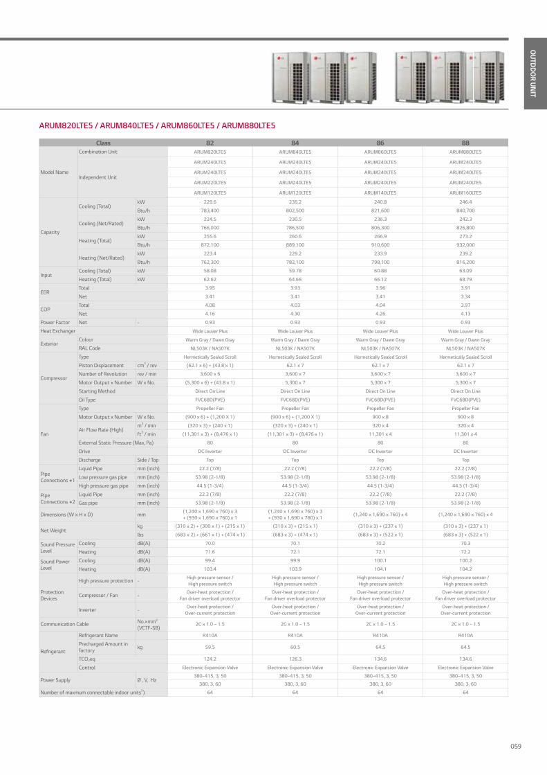
OUTDDO
R UNIT
ARUM820LTE5 / ARUM840LTE5 / ARUM860LTE5 / ARUM880LTE5
Class 82 84 86 88
Model Name
Combination Unit ARUM820LTE5 ARUM840LTE5 ARUM860LTE5 ARUM880LTE5
Independent Unit
ARUM240LTE5 ARUM240LTE5 ARUM240LTE5 ARUM240LTE5
ARUM240LTE5 ARUM240LTE5 ARUM240LTE5 ARUM240LTE5
ARUM220LTE5 ARUM240LTE5 ARUM240LTE5 ARUM240LTE5
ARUM120LTE5 ARUM120LTE5 ARUM140LTE5 ARUM160LTE5
Capacity
Cooling (Total)kW 229.6 235.2 240.8 246.4
Btu/h 783,400 802,500 821,600 840,700
Cooling (Net/Rated)kW 224.5 230.5 236.3 242.3
Btu/h 766,000 786,500 806,300 826,800
Heating (Total)kW 255.6 260.6 266.9 273.2
Btu/h 872,100 889,100 910,600 932,000
Heating (Net/Rated)kW 223.4 229.2 233.9 239.2
Btu/h 762,300 782,100 798,100 816,200
InputCooling (Total) kW 58.08 59.78 60.88 63.09
Heating (Total) kW 62.62 64.66 66.12 68.79
EERTotal 3.95 3.93 3.96 3.91
Net 3.41 3.41 3.41 3.34
COPTotal 4.08 4.03 4.04 3.97
Net 4.16 4.30 4.26 4.13
Power Factor Net - 0.93 0.93 0.93 0.93
Heat Exchanger Wide Louver Plus Wide Louver Plus Wide Louver Plus Wide Louver Plus
ExteriorColour Warm Gray / Dawn Gray Warm Gray / Dawn Gray Warm Gray / Dawn Gray Warm Gray / Dawn Gray
RAL Code NL503K / NA507K NL503K / NA507K NL503K / NA507K NL503K / NA507K
Compressor
Type Hermetically Sealed Scroll Hermetically Sealed Scroll Hermetically Sealed Scroll Hermetically Sealed Scroll
Piston Displacement cm3 / rev (62.1 x 6) + (43.8 x 1) 62.1 x 7 62.1 x 7 62.1 x 7
Number of Revolution rev / min 3,600 x 6 3,600 x 7 3,600 x 7 3,600 x 7
Motor Output x Number W x No. (5,300 x 6) + (43.8 x 1) 5,300 x 7 5,300 x 7 5,300 x 7
Starting Method Direct On Line Direct On Line Direct On Line Direct On Line
Oil Type FVC68D(PVE) FVC68D(PVE) FVC68D(PVE) FVC68D(PVE)
Fan
Type Propeller Fan Propeller Fan Propeller Fan Propeller Fan
Motor Output x Number W x No. (900 x 6) + (1,200 X 1) (900 x 6) + (1,200 X 1) 900 x 8 900 x 8
Air Flow Rate (High)m3 / min (320 x 3) + (240 x 1) (320 x 3) + (240 x 1) 320 x 4 320 x 4
ft3 / min (11,301 x 3) + (8,476 x 1) (11,301 x 3) + (8,476 x 1) 11,301 x 4 11,301 x 4
External Static Pressure (Max, Pa) 80 80 80 80
Drive DC Inverter DC Inverter DC Inverter DC Inverter
Discharge Side / Top Top Top Top Top
Pipe Connections #1
Liquid Pipe mm (inch) 22.2 (7/8) 22.2 (7/8) 22.2 (7/8) 22.2 (7/8)
Low pressure gas pipe mm (inch) 53.98 (2-1/8) 53.98 (2-1/8) 53.98 (2-1/8) 53.98 (2-1/8)
High pressure gas pipe mm (inch) 44.5 (1-3/4) 44.5 (1-3/4) 44.5 (1-3/4) 44.5 (1-3/4)
Pipe Connections #2
Liquid Pipe mm (inch) 22.2 (7/8) 22.2 (7/8) 22.2 (7/8) 22.2 (7/8)
Gas pipe mm (inch) 53.98 (2-1/8) 53.98 (2-1/8) 53.98 (2-1/8) 53.98 (2-1/8)
Dimensions (W x H x D) mm(1,240 x 1,690 x 760) x 3 + (930 x 1,690 x 760) x 1
(1,240 x 1,690 x 760) x 3 + (930 x 1,690 x 760) x 1
(1,240 x 1,690 x 760) x 4 (1,240 x 1,690 x 760) x 4
Net Weightkg (310 x 2) + (300 x 1) + (215 x 1) (310 x 3) + (215 x 1) (310 x 3) + (237 x 1) (310 x 3) + (237 x 1)
lbs (683 x 2) + (661 x 1) + (474 x 1) (683 x 3) + (474 x 1) (683 x 3) + (522 x 1) (683 x 3) + (522 x 1)
Sound Pressure Level
Cooling dB(A) 70.0 70.1 70.2 70.3
Heating dB(A) 71.6 72.1 72.1 72.2
Sound Power Level
Cooling dB(A) 99.4 99.9 100.1 100.2
Heating dB(A) 103.4 103.9 104.1 104.2
Protection Devices
High pressure protection -High pressure sensor /High pressure switch
High pressure sensor /High pressure switch
High pressure sensor /High pressure switch
High pressure sensor /High pressure switch
Compressor / Fan -Over-heat protection /
Fan driver overload protectorOver-heat protection /
Fan driver overload protectorOver-heat protection /
Fan driver overload protectorOver-heat protection /
Fan driver overload protector
Inverter -Over-heat protection /
Over-current protectionOver-heat protection /
Over-current protectionOver-heat protection /
Over-current protectionOver-heat protection /
Over-current protection
Communication Cable No.×mm2
(VCTF-SB)2C x 1.0 ~ 1.5 2C x 1.0 ~ 1.5 2C x 1.0 ~ 1.5 2C x 1.0 ~ 1.5
Refrigerant
Refrigerant Name R410A R410A R410A R410A
Precharged Amount in factory kg 59.5 60.5 64.5 64.5
TCO2eq 124.2 126.3 134.6 134.6
Control Electronic Expansion Valve Electronic Expansion Valve Electronic Expansion Valve Electronic Expansion Valve
Power Supply Ø , V, Hz380~415, 3, 50 380~415, 3, 50 380~415, 3, 50 380~415, 3, 50
380, 3, 60 380, 3, 60 380, 3, 60 380, 3, 60
Number of maxmum connectable indoor units5) 64 64 64 64
059
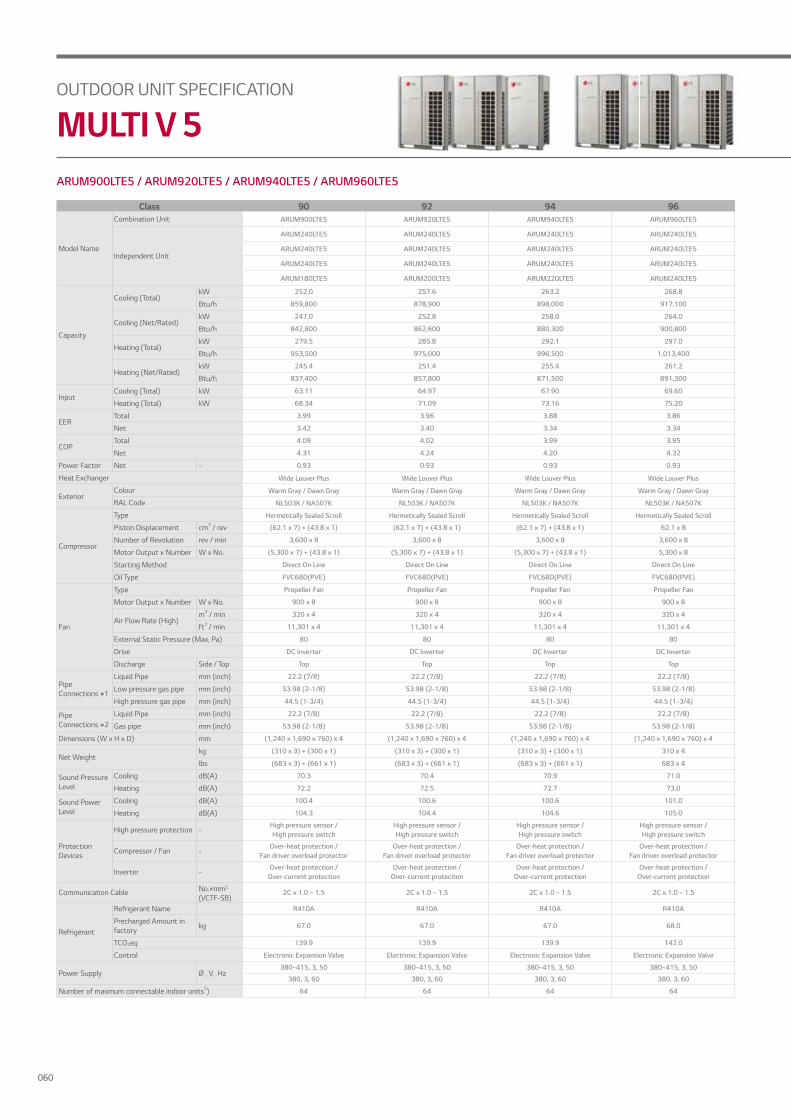
OUTDOOR UNIT SPECIFICATION
MULTI V 5ARUM900LTE5 / ARUM920LTE5 / ARUM940LTE5 / ARUM960LTE5
Class 90 92 94 96
Model Name
Combination Unit ARUM900LTE5 ARUM920LTE5 ARUM940LTE5 ARUM960LTE5
Independent Unit
ARUM240LTE5 ARUM240LTE5 ARUM240LTE5 ARUM240LTE5
ARUM240LTE5 ARUM240LTE5 ARUM240LTE5 ARUM240LTE5
ARUM240LTE5 ARUM240LTE5 ARUM240LTE5 ARUM240LTE5
ARUM180LTE5 ARUM200LTE5 ARUM220LTE5 ARUM240LTE5
Capacity
Cooling (Total)kW 252.0 257.6 263.2 268.8
Btu/h 859,800 878,900 898,000 917,100
Cooling (Net/Rated)kW 247.0 252.8 258.0 264.0
Btu/h 842,800 862,600 880,300 900,800
Heating (Total)kW 279.5 285.8 292.1 297.0
Btu/h 953,500 975,000 996,500 1,013,400
Heating (Net/Rated)kW 245.4 251.4 255.4 261.2
Btu/h 837,400 857,800 871,500 891,300
InputCooling (Total) kW 63.11 64.97 67.90 69.60
Heating (Total) kW 68.34 71.09 73.16 75.20
EERTotal 3.99 3.96 3.88 3.86
Net 3.42 3.40 3.34 3.34
COPTotal 4.09 4.02 3.99 3.95
Net 4.31 4.24 4.20 4.32
Power Factor Net - 0.93 0.93 0.93 0.93
Heat Exchanger Wide Louver Plus Wide Louver Plus Wide Louver Plus Wide Louver Plus
ExteriorColour Warm Gray / Dawn Gray Warm Gray / Dawn Gray Warm Gray / Dawn Gray Warm Gray / Dawn Gray
RAL Code NL503K / NA507K NL503K / NA507K NL503K / NA507K NL503K / NA507K
Compressor
Type Hermetically Sealed Scroll Hermetically Sealed Scroll Hermetically Sealed Scroll Hermetically Sealed Scroll
Piston Displacement cm3 / rev (62.1 x 7) + (43.8 x 1) (62.1 x 7) + (43.8 x 1) (62.1 x 7) + (43.8 x 1) 62.1 x 8
Number of Revolution rev / min 3,600 x 8 3,600 x 8 3,600 x 8 3,600 x 8
Motor Output x Number W x No. (5,300 x 7) + (43.8 x 1) (5,300 x 7) + (43.8 x 1) (5,300 x 7) + (43.8 x 1) 5,300 x 8
Starting Method Direct On Line Direct On Line Direct On Line Direct On Line
Oil Type FVC68D(PVE) FVC68D(PVE) FVC68D(PVE) FVC68D(PVE)
Fan
Type Propeller Fan Propeller Fan Propeller Fan Propeller Fan
Motor Output x Number W x No. 900 x 8 900 x 8 900 x 8 900 x 8
Air Flow Rate (High)m3 / min 320 x 4 320 x 4 320 x 4 320 x 4
ft3 / min 11,301 x 4 11,301 x 4 11,301 x 4 11,301 x 4
External Static Pressure (Max, Pa) 80 80 80 80
Drive DC Inverter DC Inverter DC Inverter DC Inverter
Discharge Side / Top Top Top Top Top
Pipe Connections #1
Liquid Pipe mm (inch) 22.2 (7/8) 22.2 (7/8) 22.2 (7/8) 22.2 (7/8)
Low pressure gas pipe mm (inch) 53.98 (2-1/8) 53.98 (2-1/8) 53.98 (2-1/8) 53.98 (2-1/8)
High pressure gas pipe mm (inch) 44.5 (1-3/4) 44.5 (1-3/4) 44.5 (1-3/4) 44.5 (1-3/4)
Pipe Connections #2
Liquid Pipe mm (inch) 22.2 (7/8) 22.2 (7/8) 22.2 (7/8) 22.2 (7/8)
Gas pipe mm (inch) 53.98 (2-1/8) 53.98 (2-1/8) 53.98 (2-1/8) 53.98 (2-1/8)
Dimensions (W x H x D) mm (1,240 x 1,690 x 760) x 4 (1,240 x 1,690 x 760) x 4 (1,240 x 1,690 x 760) x 4 (1,240 x 1,690 x 760) x 4
Net Weightkg (310 x 3) + (300 x 1) (310 x 3) + (300 x 1) (310 x 3) + (300 x 1) 310 x 4
lbs (683 x 3) + (661 x 1) (683 x 3) + (661 x 1) (683 x 3) + (661 x 1) 683 x 4
Sound Pressure Level
Cooling dB(A) 70.3 70.4 70.9 71.0
Heating dB(A) 72.2 72.5 72.7 73.0
Sound Power Level
Cooling dB(A) 100.4 100.6 100.6 101.0
Heating dB(A) 104.3 104.4 104.6 105.0
Protection Devices
High pressure protection -High pressure sensor /High pressure switch
High pressure sensor /High pressure switch
High pressure sensor /High pressure switch
High pressure sensor /High pressure switch
Compressor / Fan -Over-heat protection /
Fan driver overload protectorOver-heat protection /
Fan driver overload protectorOver-heat protection /
Fan driver overload protectorOver-heat protection /
Fan driver overload protector
Inverter -Over-heat protection /
Over-current protectionOver-heat protection /
Over-current protectionOver-heat protection /
Over-current protectionOver-heat protection /
Over-current protection
Communication Cable No.×mm2
(VCTF-SB)2C x 1.0 ~ 1.5 2C x 1.0 ~ 1.5 2C x 1.0 ~ 1.5 2C x 1.0 ~ 1.5
Refrigerant
Refrigerant Name R410A R410A R410A R410A
Precharged Amount in factory kg 67.0 67.0 67.0 68.0
TCO2eq 139.9 139.9 139.9 142.0
Control Electronic Expansion Valve Electronic Expansion Valve Electronic Expansion Valve Electronic Expansion Valve
Power Supply Ø , V, Hz380~415, 3, 50 380~415, 3, 50 380~415, 3, 50 380~415, 3, 50
380, 3, 60 380, 3, 60 380, 3, 60 380, 3, 60
Number of maxmum connectable indoor units5) 64 64 64 64
060
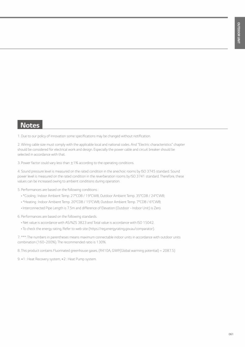
OUTDDO
R UNIT
Notes1. Due to our policy of innovation some specifications may be changed without notification.
2. Wiring cable size must comply with the applicable local and national codes. And “Electric characteristics” chapter should be considered for electrical work and design. Especially the power cable and circuit breaker should be selected in accordance with that.
3. Power factor could vary less than ±1% according to the operating conditions.
4. Sound pressure level is measured on the rated condition in the anechoic rooms by ISO 3745 standard. Sound power level is measured on the rated condition in the reverberation rooms by ISO 3741 standard. Therefore, these values can be increased owing to ambient conditions during operation.
5. Performances are based on the following conditions :
• *Cooling : Indoor Ambient Temp. 27°CDB / 19°CWB, Outdoor Ambient Temp. 35°CDB / 24°CWB;
• *Heating : Indoor Ambient Temp. 20°CDB / 15°CWB, Outdoor Ambient Temp. 7°CDB / 6°CWB;
• Interconnected Pipe Length is 7.5m and difference of Elevation (Outdoor ~ Indoor Unit) is Zero.
6. Performances are based on the following standards.
• Net value is accordance with AS/NZS 3823 and Total value is accordance with ISO 15042.
• To check the energy rating, Refer to web site (https://reg.energyrating.gov.au/comparator).
7. ***: The numbers in parentheses means maximum connectable indoor units in accordance with outdoor units combination (160~200%). The recommended ratio is 130%.
8. This product contains Fluorinated greenhouse gases. (R410A, GWP(Global warming potential) = 2087.5)
9. #1 : Heat Recovery system, #2 : Heat Pump system.
061

HYDRO KIT
HOT WATER SOLUTION

OUTDDO
R UNIT
Easy Installation Easy to install as it uses a compact and modular structure.
Sanitary Tank
Floor Heating
Cooling
Hot WaterSupply
HR Unit
MULTI V 5 + HYDRO KIT
Less Environmental Impact SolutionHigher efficency and reduction of CO2 emmisions as compared to oil or gas boilers..
CO2 Emissions
(%)
120
100
60
40
20
Gas BoilerOil Boiler
30%
76%
100%
Approx
30%On Average
Boiler
HYDRO KIT
HOT WATER SOLUTION KEY FEATURES
HYDRO KIT
063
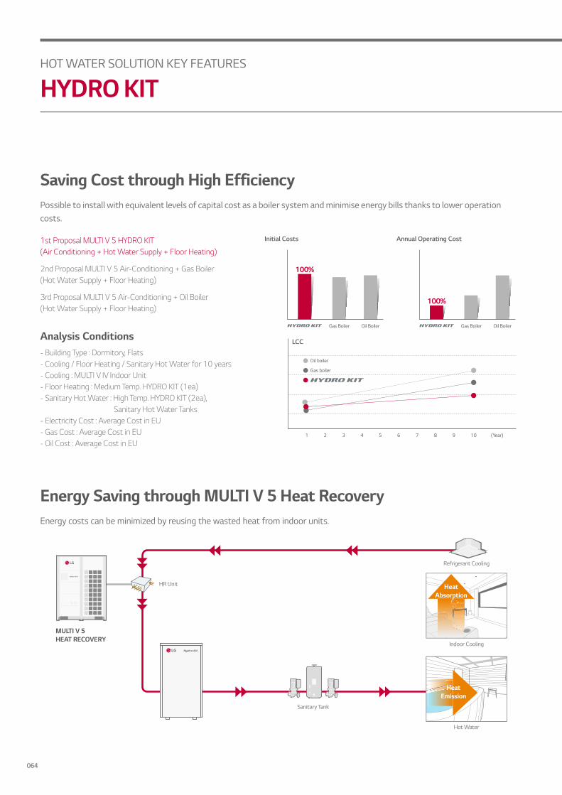
Saving Cost through High Efficiency Possible to install with equivalent levels of capital cost as a boiler system and minimise energy bills thanks to lower operation costs.
Analysis Conditions- Building Type : Dormitory, Flats- Cooling / Floor Heating / Sanitary Hot Water for 10 years- Cooling : MULTI V IV Indoor Unit- Floor Heating : Medium Temp. HYDRO KIT (1ea)- Sanitary Hot Water : High Temp. HYDRO KIT (2ea), Sanitary Hot Water Tanks- Electricity Cost : Average Cost in EU- Gas Cost : Average Cost in EU- Oil Cost : Average Cost in EU
1st Proposal MULTI V 5 HYDRO KIT(Air Conditioning + Hot Water Supply + Floor Heating)
2nd Proposal MULTI V 5 Air-Conditioning + Gas Boiler (Hot Water Supply + Floor Heating)
3rd Proposal MULTI V 5 Air-Conditioning + Oil Boiler (Hot Water Supply + Floor Heating)
(Year)1
LCC
2 3 4 5 6 7 8 9 10
Gas boiler
Oil boiler
Initial Costs
Oil BoilerGas Boiler
100%
Annual Operating Cost
Oil BoilerGas Boiler
100%
Energy Saving through MULTI V 5 Heat Recovery Energy costs can be minimized by reusing the wasted heat from indoor units.
HR Unit
Sanitary Tank
MULTI V 5HEAT RECOVERY
Hot Water
Refrigerant Cooling
Heat Absorption
Indoor Cooling
Heat Emission
HOT WATER SOLUTION KEY FEATURES
HYDRO KIT
064
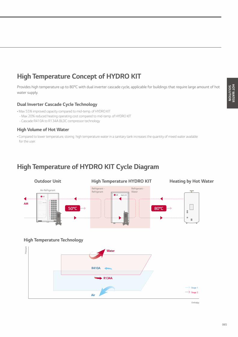
HO
T WATER
SOLU
TION
Dual Inverter Cascade Cycle Technology• Max 55% improved capacity compared to mid-temp. of HYDRO KIT - Max 20% reduced heating operating cost compared to mid-temp. of HYDRO KIT - Cascade R410A to R134A BLDC compressor technology
High Volume of Hot Water• Compared to lower temperature, storing high temperature water in a sanitary tank increases the quantity of mixed water available
for the user.
High Temperature Concept of HYDRO KIT Provides high temperature up to 80°C with dual inverter cascade cycle, applicable for buildings that require large amount of hot water supply.
High Temperature Technology
Pres
sure
Enthalpy
Air
Water
R410A
R134A
Stage 2
Stage 1
Outdoor Unit High Temperature HYDRO KIT Heating by Hot Water
AIR
Air-RefrigerantRefrigerant - Water
Refrigerant -Refrigerant
50°C 80°C
High Temperature of HYDRO KIT Cycle Diagram
065

Office University / School Hospital / Clinic
Shopping Mall / Restaurant Hotel / Resort Factory Facilities
Various Applications Applicable to a variety of facilities including hospitals, residences and resorts that need floor heating and domestic hot water supply.
Hotel Application It is possible to operate cooling and heating constantly at the same time during the summer, to provide hot water for bathrooms by using waste heat energy of indoor cooling from an indoor unit.
Office Application Hot water can be supplied at all times in the office by cooling the HR unit to warm up the sanitary tank, using waste energy.
HOT WATER SOLUTION KEY FEATURES
HYDRO KIT
066

* This product contains Fluorinated Greenhouse Gases. (R410A, R134A)Note : 1. Capacities are based on the following conditions : - Heating : Indoor 20°C (68°F) DB / 15°C (59°F) WB, Outdoor 7°C (44.6°F) DB / 6°C (42.8°F) WB, Water Inlet 55°C (131°F) / Outlet 65°C (149°F) 2. Piping Length : Interconnected Pipe Length = 7.5m 3. Difference Limit of Elevation (Outdoor ~ Indoor Unit) is Zero. 4. MULTI V S 4HP (ARUN040GSS0, ARUN040LSS0) cannot be connected to Hydro Kit. 5. MULTI V Water S cannot be connected to Hydro Kit.
Type High Temp. High Temp.Model ARNH04GK3A4 ARNH08GK3A4
Power Supply Ø / V / Hz 1 / 220~240 / 501 / 220 / 60
1 / 220~240 / 501 / 220 / 60
Capacity (Rated)Cooling kW - -
Heating kW 13.8 25.2
Power InputCooling Nomal kW - -
Heating Nomal kW 2.3 5.0
Water OutletTemperature
Cooling Min °C - -
Heating Max °C 80°C 80°C
Casing Painted Steel Plate Painted Steel Plate
Dimensions Body W x H x Dmm 520 × 1,080 × 330 520 × 1,080 × 330
inch 20-15 / 32 x 42-17 / 32 x13 20-15 / 32 x 42-17 / 32 x13
Net Weight kg (lbs) 88.0 (194.0) 94.0 (207.2)
Heat ExchangerRefrigerant to Water
Type Brazed Plate HEX Brazed Plate HEX
Rated Water Flow L/min 19.8 36.0
Head Loss kPa 5.0 20.0
Refrigerant to Refrigerant Type Brazed Plate HEX Brazed Plate HEX
Compressor Type Twin Rotary Inverter Twin Rotary Inverter
Piping Connections
Water SideInlet inch Male PT 1 Male PT 1
Outlet inch Male PT 1 Male PT 1
Refrigerant SideLiquid Side mm (inch) 9.52 (3/8) 9.52 (3/8)
Gas Side mm (inch) 15.88 (5/8) 19.05 (3/4)
Drain Piping Connection mm (inch) Male PT 1 Male PT 1
Sound Pressure LevelCooling dB (A) - -
Heating dB (A) 43 43
Refrigerant
Refrigerant to RefrigerantRefrigerant Type R410A R410A
Control EEV EEV
Refrigerant to Water
Refrigerant Type R134A R134A
Precharged Amount kg (lbs) 2.3(5.1) 3.0(6.6)
Control EEV EEV
Operation Range
Conntected to Heat PumpCooling °C (DB) - -
Heating °C (DB) -20°C ~ 35°C -20°C ~ 35°C
Conntected to Heat RecoveryCooling °C (DB) - -
Heating °C (DB) -20°C ~ 43°C -20°C ~ 43°C
Combination RatioOnly Hydrokit Min ~ Max % 50 ~ 100 50 ~ 100
Hydrokit + Standard IDUs Min ~ Max % 50 ~ 130 50 ~ 130
ARNH04GK3A4/ ARNH08GK3A4 HO
T WATER
SOLU
TION
067
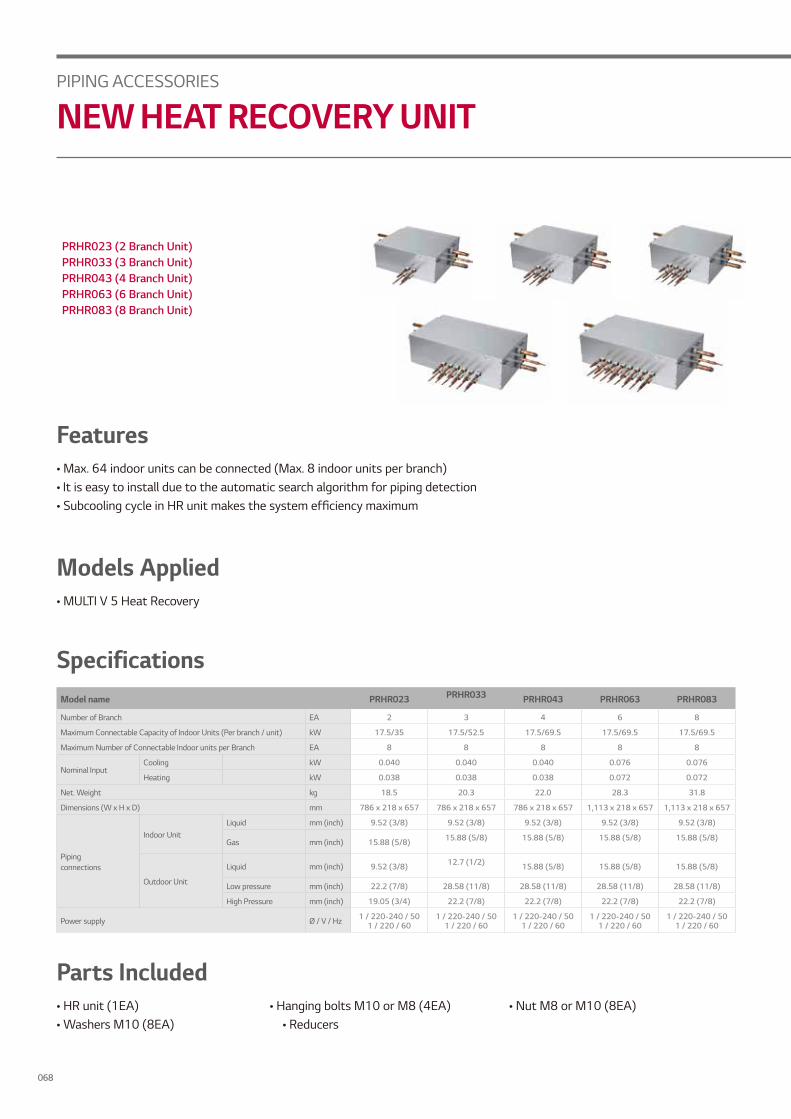
PRHR023 (2 Branch Unit)PRHR033 (3 Branch Unit)PRHR043 (4 Branch Unit)PRHR063 (6 Branch Unit)PRHR083 (8 Branch Unit)
Features• Max. 64 indoor units can be connected (Max. 8 indoor units per branch)• It is easy to install due to the automatic search algorithm for piping detection• Subcooling cycle in HR unit makes the system efficiency maximum
Models Applied• MULTI V 5 Heat Recovery
Parts Included• HR unit (1EA) • Hanging bolts M10 or M8 (4EA) • Nut M8 or M10 (8EA)• Washers M10 (8EA) • Reducers
Model name PRHR023 PRHR033 PRHR043 PRHR063 PRHR083
Number of Branch EA 2 3 4 6 8
Maximum Connectable Capacity of Indoor Units (Per branch / unit) kW 17.5/35 17.5/52.5 17.5/69.5 17.5/69.5 17.5/69.5
Maximum Number of Connectable Indoor units per Branch EA 8 8 8 8 8
Nominal InputCooling kW 0.040 0.040 0.040 0.076 0.076
Heating kW 0.038 0.038 0.038 0.072 0.072
Net. Weight kg 18.5 20.3 22.0 28.3 31.8
Dimensions (W x H x D) mm 786 x 218 x 657 786 x 218 x 657 786 x 218 x 657 1,113 x 218 x 657 1,113 x 218 x 657
Pipingconnections
Indoor UnitLiquid mm (inch) 9.52 (3/8) 9.52 (3/8) 9.52 (3/8) 9.52 (3/8) 9.52 (3/8)
Gas mm (inch) 15.88 (5/8) 15.88 (5/8) 15.88 (5/8) 15.88 (5/8) 15.88 (5/8)
Outdoor Unit
Liquid mm (inch) 9.52 (3/8) 12.7 (1/2) 15.88 (5/8) 15.88 (5/8) 15.88 (5/8)
Low pressure mm (inch) 22.2 (7/8) 28.58 (11/8) 28.58 (11/8) 28.58 (11/8) 28.58 (11/8)
High Pressure mm (inch) 19.05 (3/4) 22.2 (7/8) 22.2 (7/8) 22.2 (7/8) 22.2 (7/8)
Power supply Ø / V / Hz 1 / 220-240 / 501 / 220 / 60
1 / 220-240 / 501 / 220 / 60
1 / 220-240 / 501 / 220 / 60
1 / 220-240 / 501 / 220 / 60
1 / 220-240 / 501 / 220 / 60
Specifications
PIPING ACCESSORIES
NEW HEAT RECOVERY UNIT
068

Convenient Free ZoningMULTI V Heat Recovery provides flexible control over individual zones for the user’s convenience
• Individual Control- Excellent individual control over spaces ventilation needed
• Zone Control- Max. of 8 indoor units can be connected for one branch- Max. of 64 indoor units can be connected for one HR unit- Same opeational model can be operated by indoor units
with zone control function installed
• Combination of Individual and Zoning Installations- Flexible piping design
• Save Product and Installation Cost
Reducers for Indoor Unit and HR Unit
[Zoning Control]
HR Unit
Zoning Control (Max Indoor Unit 8EA)
(Unit : mm)
Model Name Liquid High pressure Low pressure
Indoor Unit Reducer
HR Unit Reducer
PRHR023
PRHR033PRHR043PRHR063 PRHR083
Office
Room
Kitchen
IT Room
PIPING
A
CCESSO
RIES
069

Improving Service Workability
Expansion of connection capacity
Can inspect valves and PCBs under the product.(looking up at the product)
• Expansion of connection capacity per port : (old) 15kW (new) 17kW• Expansion of total connectable capacity : (old) 60kW (new) 71.87kW
Conventional
Previous Model
New
New
At least 450 mm of space is required to open the control cover and to inspect or repair the product.
min 450mm
4 ports
Max 60kW
The control cover can be opened (disassembled) in the downward direction. → Error code check and simple check & repair are possible.
Inspection door
Control Cover
Max 71.87kW
8 ports
15kW / port 17kW / port
PIPING ACCESSORIES
NEW HEAT RECOVERY UNIT
070

Easy Series ConnectionSeries connection can be installed without pipes crossing.
Series connectionin the same direction
Series connectionin the reverse direction
Crossedpiping
Reduce NoiseCooling Heating changeover noise improvement
LG Previous Model New
13dBdB(A)
LG Previous Model New
PIPING
A
CCESSO
RIES
071

Find out morelg.com/au/commercial-air-conditioning