Leviton Strategies
88
FOR VOICE AND DATA SYSTEMS Leviton Telcom Strategies Series $10.00
-
Upload
cumfortinn -
Category
Documents
-
view
365 -
download
1
Transcript of Leviton Strategies

FOR VOICE AND DATA SYSTEMS
Leviton Telcom Strategies Series$10.00
LE
VITO
N TE
LC
OM
1-8
00-9
22-6
229
WIR
ING
STR
ATE
GIE
S F
OR
VO
ICE
AN
D D
ATA
SY
STE
MS
V
OLU
ME
ON
E
TERMINATING ONTO 110 BLOCKS
DON’T allow pairs to untwist more than the maximum allowed for the cable’s Category rating:
Above Category 5: <1/2" max untwistCategory 5:1/2" max. untwistCategory 4:1" max. untwistCategory 3:3" max. untwist
DO maintain pair twisting closeto the termination point.(Also note that the cable jacketis maintained as close to the termination as possible.)
3.1.1 STAR TOPOLOGYTIA-568-A specifies a star topology: a hierarchicalseries of distribution levels. In the backbone are themain distribution frame (MDF) and the optional intermediate distribution frame (IDF). Only one IDF isallowed between the MDF and telecommunicationscloset.
Fig. 3-1. Typical Commercial Building Wiring Topology
EQUIPMENTROOM(S)
TELECOMMUNICATIONSCLOSETS (AND/ORINTERMEDIATEDISTRIBUTION FRAMES)
HORIZONTAL WIRING (PATHWAYS)FROM THE TELECOMMUNICATIONSCLOSET TO THE INDIVIDUALWORKSTATIONS
BACKBONEWIRING
SERVICEENTRANCE
ENTRANCEROOM
INTERBUILDINGBACKBONEWIRING
MAINDISTRIBUTIONFRAME
WS
WS
WS WS
WS
WS
WSWS
WS
ALL THE INFORMATION YOU’LL NEEDALL THE INFORMATION YOU’LL NEEDto help you successfully wire a home or office.
Includes detailed information on the latest standards practices.
Complete testing and troubleshooting tips.
Includes detailed information on the latest standards practices.
Full diagrams on smart wiringruns for telephone, data, audio and security systems in the home.
Complete testing and troubleshooting tips.
Sections include copper cable wiring for commercial and residential installations including LANs, modems,faxes, audio/video systems and centralized security systems.

Wiring Strategies –Voice and Data Systems
2BOOK
RESIDENTIALAND LIGHTCOMMERCIALAPPLICATIONS
——EIA/TIA570
CompliantInstallation
OVERVIEWTIA WiringSTANDARDS
BO
OK1
OVERVIEWTIA WiringSTANDARDS
BO
OK
1
BO
OK4
F I B E RO P T I CI N S T A L L A T I O NCOMPLIANT WITHC O M M E R C I A LBUILDING WIRINGS T A N D A R D S
——TIA
568-A
3BOOK
C O P P E RCABLING FORCOMMERCIALAPPLICATIONS
——TIA
568ACompliantInstallation
© Copyright 1998 Leviton Manufacturing Co., Inc.
For technical information, call 1 (800) 722-2082 • For product information, call 1 (800) 922-6229 • website: www.levitontelcom.com • e-mail: [email protected]
1 EIA/TIA Standards Overview …………………… 1-1The Category Rating System forUnshielded Twisted Pair ………………………… 1-2Specifications for Levels, Categories andEmerging Standards …………………………… 1-3Other Network Applications–150Ω STP,100VG-ANYLAN, 100Base-T, GigaBit Ethernet,1000Base-T, ATM ……………………………… 1-4
TABLE OF CONTENTSBOOK 1TELECOMMUNICATIONS STANDARDS OVERVIEW
2
4
3
BOOK 2RESIDENTIAL AND LIGHT COMMERCIALINSTALLATIONS (THE TIA-570 STANDARD)Wiring Overview–Circuits, Polarity, Color Codes... 2-1Installation Practices …………………………… 2-3Tips on Quality Installations …………………… 2-9Residential Wiring Diagrams …………………… 2-10
Tools …………………………………………… 2-13Rough-In Wiring Tests ………………………… 2-15Final Verification Testing ………………………… 2-18Testing Security Systems ……………………… 2-19
Benefits of TIA-568-A Compliance ……………… 3-1100Ω UTP Cabling Systems …………………… 3-6150Ω STP Cabling Systems …………………… 3-9Telecommunications Closets …………………… 3-11Cabling System Administration (TIA-606) ……… 3-13Do/Don’t Installation Photos …………………… 3-15
BOOK 3COMMERCIAL INSTALLATIONS(THE TIA 568-A STANDARD)
BOOK 4FIBER OPTIC INSTALLATIONS(THE TIA-568-A STANDARD)
APPENDICES
Overview ………………………………………… 3-19Testing Benefits ………………………………… 3-19Definition of Channel vs. Link …………………… 3-19
Overview of Fiber Optic Technology …………… 4-1Fiber Cable Construction ………………………… 4-2Optical Fiber Transmission ……………………… 4-3Installing Optical Cable ………………………… 4-4Handling Fiber Optic Cable ……………………… 4-5Fiber Optic Cable Termination …………………… 4-6Fiber Connectors ………………………………… 4-7CrossConnect Panels & Workstation Outlets …… 4-10
System Verification Testing …………………… 4-13Test Equipment ………………………………… 4-13Required Tests ………………………………… 4-13Testing Procedure ……………………………… 4-13Bandwidth Verification ………………………… 4-14Other Things To Do Before Start-Up …………… 4-14Troubleshooting ………………………………… 4-14
Appendix A: Glossary of Terms from ‘ATM’ to ‘UTP’Appendix B: Network DiagramsAppendix C: Jack Pin Designations & Color Codes
Appendix D: USOC Color CodesAppendix E: Standards Document Contact InformationAppendix F: Product Ordering Guide
BOOK 2TTESTING & TROUBLESHOOTING RESIDENTIALAND LIGHT COMMERCIAL WIRING SYSTEMS
BOOK 3-TTESTING CATEGORY 5 WIRING SYSTEMS(TSB-67)
BOOK 4-TFIBER OPTIC TESTING & TROUBLESHOOTING(TIA-568-A AND TIA-526-14, METHOD B)
Other Important Information …………………… 1-5Safety and Installation Information ……………… 1-6
i

Leviton Telcom is a business unit of Leviton Manufacturing Co. Inc., a world-leadingmanufacturer of wiring devices since 1906. At Leviton Telcom, EXCELLENCE INCONNECTIVITY AND SUPPORT is the underlying business philosophy that gives youextra value from every product and service we offer. Through product design, selection,performance, installation, and application information, our commitment to excellencemakes us your best single resource for all of your copper and fiber wiring interfaces fromthe most basic telephone systems to high-end data networks.
EXCELLENCE IN CONNECTIVITYOne of the most trusted names in the industry, LevitonTelcom stands apart as the company which believes productinnovation, system design and technical assistance areequally important. Leviton is well equipped to provide productline breadth and quality for a complete system of voice anddata wiring connectivity products to support a full range ofapplications and requirements.
· Quality workmanship with on-site productdesign, manufacture, and testing.
· All products are tested to exceed thelatest industry standards, includingCategory 3, Category 5 Power Sum,proposed Category 5e and proposedCategory 6.
· Made-in-USA Products.
· UL Listed and CSA Certified Products.
· ISO 9001 Registered Company.
EXCELLENCE IN SUPPORTLeviton Telcom employs an extensivenetwork of support services for ourcustomers. Customer Service and SalesSupport provide product ordering servicesand supporting literature. An extensive Technical SupportDepartment includes highly trained RegisteredCommunications Distribution Designers (RCDDs) to answerspecific questions about products, and broad applicationand installation questions. Leviton is also an active memberof many important industry regulatory and standards bodiesincluding TIA and BICSI to ensure performance and standardscompliance.
THE ONE SOURCE FOR ALL YOURVOICE & DATA WIRING NEEDS.
ii
LEVITON TELCOM:

CERTIFIED CABLING SYSTEMPROGRAMAs the TIA cautions, the quality of workmanshipduring installation can make or break theperformance of high-speed structured cablingsystems. Leviton’s Certified Cabling SystemProgram is a strong, synergized program whichcoordinates, controls and assures quality for allaspects of your high-performance cablingsystem, including system design, installation,testing and maintenance by the most highly qualifiedinstallers in the industry. It is Leviton’s guarantee that anysystem installed by a CCS installer will operate reliably andtrouble-free.
LIFETIME WARRANTYIn league with product certification, Leviton produces
the highest quality products available and backsthem with one of the strongest warranties in the
industry. Leviton’s Lifetime Warranty on partsand performance provides you with the
assurance that a Leviton CCS installedsystem will support any current and
future application developed for TIA/EIA-568-A. It also covers your
system against defects inmaterial and workmanship for
all Leviton CCS productsfor as long as they are
installed in a certifiedcabling system.
iii

PURPOSEThis document provides a basic overview of the purpose and application ofindustry standard EIA/TIA-568-A and –570 wiring systems, developed by theElectronic Industry Association (EIA) and the Telecommunications IndustryAssociation (TIA) for twisted pair and fiber optic cabling.
SCOPEThis book contains information about horizontal wiring system design,installation and administration as suggested by the following standards:Commercial Building Wiring Standard, TIA-568-A (incorporating theTelecommunications Systems Bulletins TSB-36 and TSB-40); Residential andLight Commercial Wiring Standard, TIA-570 (incorporating Standards Proposall3490-A); Wiring Administration Standard, TIA-606; and TransmissionSpecifications For Field Testing of UTP Cabling Systems, TSB-67.
This document is intended only as an overview of standards-compliantinstallation practices, to serve as a helpful reference for horizontal wiringsystem designers and installers. This document does not attempt to coverbackbone wiring materials or practices, or non-installation issues exceptwhere pertinent. This document is not a replacement for reading andunderstanding the actual standards documents to which it refers. LevitonTelcom recommends that you read and understand the standards documentsbefore installing telecommunications wiring and devices.
HOW TO USE THIS GUIDEThis guide is divided into four sections or “books”, allowing you to read someor all of the sections for information of interest on wiring concepts andpractices, or easily consult specific sections for field reference. Levitonrecommends that you initially read all of the sections, in consecutive order.
PLEASE NOTEThis booklet contains information for use solely by professional wiring systemdesigners and installers. While Leviton believes the information containedherein to be accurate and current as of publication, it makes no warranty of anykind, express or implied. Leviton assumes no liability or obligation of any kind,and the reader is cautioned to abide by all national and local electrical andtelephone codes, rules and regulations, and to use common sense in utilizingthis information.
ST® is a registered trademark of AT&T. Other trademarks are the registered trademarks of theirrespective owners.
ABOUT THIS GUIDE
For product ordering, callCustomer Service at1-800-722-2082. Fortechnical and applicationinformation, call 1-800-722-2082. For productinformation and to orderliterature, call 1-800-922-6229.
Information is accurate atthe time of printing, but issubject to change at anytime without notice.
iv

OVERVIEWTIA WiringSTANDARDS
BO
OK1Wiring Strategies for Voice and Data Systems
© Copyright 1998 Leviton Manufacturing Co., Inc.
For technical information, call 1 (800) 722-2082 • For product information, call 1 (800) 922-6229 • website: www.levitontelcom.com • e-mail: [email protected] 1-1
TELECOMMUNICATIONS STANDARDS OVERVIEW
1.1 EIA/TIA STANDARDS CREATE AUNIVERSAL WIRING TOPOLOGYTO SUPPORT MULTIPLEAPPLICATIONS
The TIA standards development committees (TR-41.8)were formed to develop standards for structured cablingsystems and infrastructure. These committees consistof the major cabling system vendors, component vendors,and liaisons to applications groups.
In the past, the telecommunication industry respondedto market needs with separate standards that mirroredindustry application implementations. Token Ring ran on150Ω Shielded Twisted Pair. 3270 ran on RG-62 coax.Ethernet ran on RG-58 coax. Phones were run on Quadwire or 100Ω unshielded twisted pair. And each of theseapplications had its own standard.
As the number of installations of each application grew,more standards were needed to address performanceand compatibility between suppliers. For example, lower-cost wiring systems were added to Ethernet, Token Ringand FDDI—but each application still required a uniquecabling system.
All these separate standards added up to one bigheadache for installers and end-users because as morenetwork types were added, the installation andmaintenance of multiple—and often incompatible—wiringsystems within buildings and campuses became verydifficult.
The diversity and number of available services, and thecontinual addition of new services, resulted in seriouslimitations regarding system operation, adaptability andmaintenance. As a result, user demand grew for acommon cabling system that would accommodate allapplications. EIA/TIA-568-A was developed in responseto this need by establishing a standard for a genericcabling system that can accommodate manyapplications.
Like many earlier application-specific standards, theEIA/TIA-568-A wiring standard and Category ratingsystem reflect prevailing practices by a majority of thetelecommunications industry. Also, in response to marketdemands for higher data rate applications at lowercosts, the TIA defined specifications for Category 5 UTP,Extended 150Ω STP wiring systems, and EnhancedCategory 5 (Category 5e) and Category 6, as well as a
standard for Residential/Light Commercial Wiring—EIA/TIA-570.
At the time of publication, several addenda to EIA/TIA-568-A were in various stages of development. Oneaddendum sets additional requirements for Category 5installations to insure compatibility with applicationssuch as 1000Base-T (most installed Cat 5 systemsmeets these requirements). Another addendumaddresses Enhanced Category 5 channel and linkrequirements, called Category 5e. Still another proposalseeks to define parameters for Category 6.
Because standards are still being adopted and updated,many people in the telecommunications industry areconfused about which wiring systems apply to theircurrent and anticipated applications. With so manyproducts and applications being constantly introduced,many data system managers and specification engineersaren’t even sure what equipment and applications willrun on various wiring systems. It is the purpose of thispublication to reduce the confusion by explaining thestandards requirements in simpler terms.
1.1.1 COMPLIANT PRODUCTS ALONEDON’T GUARANTEE A COMPLIANTSYSTEM
With so much emphasis on compliant components,many forget that systems will not comply or perform tothe desired Category rating unless proper installationpractices are followed. TIA-568-A warns, “It should benoted that meeting requirements for connector categories3, 4, and 5 is not sufficient in itself to ensure requiredsystem performance.” This statement is also applicableto the proposed Cat 5e and Cat 6 installations.
Proper installation and connector termination are criticalto a network’s overall performance and compliance. TIA-568-A states, “Cables used with connectors of the sameCategory rating will experience minimum performancedegradation when properly installed.” Consult thestandard for these installation requirements.
1.1.2 BENEFITS OF INSTALLINGSTANDARDIZED SYSTEMS
The TIA had several goals when writing the standard.They wanted the cabling system to be simple and easyto administer; for commercial applications, the cablingsystem had to accommodate all current applications up
1

Achieving Category Performance: Requirements Beyond Jacks & Cable
OVERVIEWTIA WiringSTANDARDS
BO
OK1
For technical information, call 1 (800) 722-2082 • For product information, call 1 (800) 922-6229 • website: www.levitontelcom.com • e-mail: [email protected]
© Copyright 1998 Leviton Manufacturing Co., Inc.
1-2
The Categories characterize commercial building wiringsystems for 100Ω UTP cables as follows:
Category 3 = 16 MHz (10 Mbps)
Category 4 = 20 MHz (16 Mbps)
Category 5 = 100 MHz (originally 100 Mbps, will run ATM and 1000Base-T)
Proposed Addendums to EIA/TIA-568-A:
Category 5e = 100 MHz (1000Base-T & faster ATM )
Category 6 = 200 MHz (beyond 1000Base-T)
You will notice that the Category rating systemonly applies to 100Ω UTP wiring systems. However,EIA/TIA-568-A does allow 150Ω STP (also called Type 1)and 62.5/125 µm multi-mode optical fiber. TSB-53,“Extended Specifications for 150-ohm STP Cables andData Connectors,” extends the 150Ω cabling systemfrom 20 MHz (Type 1) to 300 MHz (Type 1A). No extendedoperating frequency wiring systems for optical fiber areplanned.
1.2.3 INTERPRETING COMPLIANCE ANDPERFORMANCE TEST DATA
In order to determine compliance with Categoryspecifications, cable and connecting hardware (jacks)must fulfill certain parameters as defined by EIA/TIA-568-A. For full Category compliance, jacks and cable mustmeet EIA/TIA-568-A electrical and mechanicalspecifications and transmission requirements.
Attenuation, near-end crosstalk (NEXT) and return lossare signal-degrading factors which greatly affect asystem’s transmission capability. The proportions of thesefactors determines a cable or connector’s Category ofcompliance.
Attenuation is the loss of signal strength duringtransmission, where the received signal is lower in strengththan the transmitted signal due to losses in the transmissionmedium (such as caused by resistance in the cable).
NEXT is a distortion of the incoming signal, caused by thecoupling of noise from one pair of wires to another.
Return loss is the measure of the similarity of theimpedance of a transmission line and the impedance atits termination.
When choosing a system, be sure to compare its test dataagainst the Standards requirements for the performanceyou want.
to and including 100 Mbps. There are applications inexcess of 100 Mbps that will run on existing Category 5cable and there are even faster applications plannedthat are generating the requirements for higher levelstandards. In addition, they wanted to establish standardinstallation procedures and practices in order toguarantee optimal performance.
1.2 CATEGORY RATING SYSTEMTo simplify choosing telecommunications media forvarious application requirements, componentperformance can be ascertained by its Level or Categoryrating. All system components should be chosen fromthe same category rating to ensure proper performance.
1.2.1 THE LEVEL RATING SYSTEMThe Level system was developed by distributors toclassify cabling system components such as wire andjacks into grades of performance. The Level system,though quite loosely defined, sparked industry demandfor a single cabling system for all communications, andfor better classification of product performance.
The only Levels that are currently in use are Level 1 andLevel 2. These Levels are defined by UL as follows:
Level 1 = Plain Old Telephone Service (POTS)
Level 2 = IBM Type 3 cabling system
1.2.2 THE CATEGORY RATING SYSTEMFOR UTP
The original EIA/TIA-568 only defined requirements forapplications up to 16 MHz. While this was sufficient formany applications such as voice, ISDN, 4 Mbps TokenRing, and 10Base-T, new applications with higher datarates were not addressed. The Category rating systemwas developed by the TIA in response to industrydemands for higher data rate specifications onapplications over unshielded twisted pair.
The Category information was released in two TechnicalService Bulletins, TSB-36 and TSB-40. The TSB'srecommended changes and additions to EIA/TIA-568and added the Category rating system, replacing the oldLevel System. TSB-36 covered additional specificationsfor UTP cables. TSB-40 added specifications forconnecting devices, such as jacks, cross-connect blocks,and patch panels. These TSB's have now been integratedinto the main body of the EIA/TIA-568-A standarddocument.

OVERVIEWTIA WiringSTANDARDS
BO
OK1Wiring Strategies for Voice and Data Systems
© Copyright 1998 Leviton Manufacturing Co., Inc.
For technical information, call 1 (800) 722-2082 • For product information, call 1 (800) 922-6229 • website: www.levitontelcom.com • e-mail: [email protected] 1-3
1.3 OVERVIEW OF SPECIFICATIONSFOR LEVELS, CATEGORIES ANDEMERGING STANDARDS
1.3.1 LEVEL 1Level 1 is loosely defined as the minimum cabling systemfor analog voice service or Plain Old Telephone Service(“POTS”). In the past, this definition would have alloweda system as rudimentary as barbed wire running down afence line to be considered “Level 1”. However, today,although no actual performance requirements exist forLevel 1, several minimum definitions have been developedto ensure that no harm occurs to the phone companynetwork.
For Level 1 wiring systems, FCC Part 68 defines theminimum acceptable characteristics of wire, plugs andjacks; UL 1863 defines the minimum safety requirementsfor wire and jacks; and ICEA S-80-576 and Bellcore48007 define the manufacturing requirements for cordsand cables. Most commonly available Level 1 jacks andplugs will perform adequately for analog voice service, aslong as they comply with FCC Part 68 requirements.
For Level 1 short-run residential single-line voiceapplications, or any application for that matter, it isrecommended that “quad” wire (four non-twisted wireswithin a cable jacket) should no longer be used unlessit is already in place for single-line analog applicationsonly. Unshielded twisted pair (UTP), four twisted pairswithin a cable jacket is recommended for all new andmulti-line installations, longer runs, and commercialapplications in order to minimize pair-to-pair crosstalkand 60 Hz hum.
Screw terminal or binding post termination types aretypically sufficient to meet Level 1 needs. Most commoninsulation displacement type cross-connect blocks (suchas 66 clip, 110, and others) exceed Level 1 needs. Wire-wrap and solder blocks should be avoided for maintenancereasons.
Level 1 Wire Types:- 100Ω UTP is preferable, and requiredfor any multi-line application.
- “Quad” wire is not recommended for dataor network installations, but can functionadequately in certain limited situations (i.e.single-line analog voice applications whereit has already been installed).
Level 1 Technical Requirements defined by:- FCC Part 68
- ICEA S-80-576- Bellcore 48007
Level 1 Performance Criteria:
- None specified.
Level 1 Safety Requirements defined by:
- UL 1459 (Telephone)- UL 1863 (Wire and Jacks)- NEC® 1993, Article 800-4
1.3.2 LEVEL 2UL defines Level 2 as the IBM Type 3 cabling system.IBM Type 3 cable, connectors and baluns were designedas a higher-grade 100 ohm UTP system capable ofoperating 1 Mbps Token Ring, 5250 and 3270applications over shortened distances. The higherfrequency IBM 5250 and 3270 applications will functionon Type 3 cables even though the cable is onlycharacterized to 1 MHz; impedance-matching devicesare required to interface these IBM applications to theType 3 media (see Table 1-1, page 1-9). Typicalapplications include voice and ISDN.
Level 2 Wiring Types:- 100Ω UTP
Level 2 Technical Requirements defined by:- FCC Part 68- GA27-3773-1, IBM Cabling System Technical Interface
Level 2 Safety Requirements:- UL 1459 (Telephone)- UL 1863 (Wire and Jacks)- NEC 1993, Article 800-4
1.3.3 CATEGORY 3Category 3 is characterized to 16 MHz, to supportapplications up to 10 Mbps.
Typical applications are: voice, ISDN, 4 Mbps TokenRing, and 10Base-T.
Category 3 Wiring Types: - 100Ω UTP rated Category 3
Category 3 Technical Specifications defined by: - FCC Part 68 - EIA/TIA-568-A
Category 3 Safety Requirements defined by: - UL 1459 (Telephone)
- UL 1863 (Wire and Jacks)
- NEC 1993, Article 800-4

Achieving Category Performance: Requirements Beyond Jacks & Cable
OVERVIEWTIA WiringSTANDARDS
BO
OK1
For technical information, call 1 (800) 722-2082 • For product information, call 1 (800) 922-6229 • website: www.levitontelcom.com • e-mail: [email protected]
© Copyright 1998 Leviton Manufacturing Co., Inc.
1-4
1.3.4 CATEGORY 4Category 4 defines cabling system requirements tosupport 20 MHz. Typical applications are from voiceto 16 Mbps Token Ring.
Category 4 Wiring Types:
- 100Ω UTP rated Category 4
Category 4 Technical Specifications defined by:
- FCC Part 68
- EIA/TIA-568-A
Category 4 Safety Requirements:
- UL 1459 (Telephone)
- UL 1863 (Wire and Jacks)
- NEC 1993, Article 800-4
1.3.5 CATEGORY 5Category 5 is a further extension of the EIA/TIA-568-Acabling system to 100 MHz. Originally, typicalapplications ranged from voice to 100 Mbps, andTP-PMD; with the addition of Draft Addendum 4 to the568-A standard, additional requirements were proposedfor a minimally compliant Category 5 channel. They wereintended to further characterize the existing cablingplant. Although these are new specifications, the existingworst-case two-connector (interconnect) topologiescompliant with TIA/EIA-568-A are expected to meetthese requirements. Other topologies are supported aslong as they meet the ELFEXT and Return Lossrequirements of this document.
Category 5 Wiring Types:
- 100Ω UTP rated Category 5
Category 5 Technical Specifications which apply to Category 5:
- FCC Part 68
- EIA/TIA-568-A
Category 5 Safety Requirements which apply to Category 5:
- UL 1459 (Telephone)
- UL 1863 (Wire and Jacks)
- NEC 1993, Article 800-4
1.3.6 CATEGORY 5ECategory 5e is another extension (Addendum 5) of theEIA/TIA-568-A cabling system to 100 MHz. As withCategory 5, the existing worst-case two-connector (cross-
connect) topologies compliant with TIA/EIA-568-A areexpected to meet these requirements, and othertopologies are supported as long as they meet theELFEXT and Return Loss requirements of this document.In addition, Cateogry 5e cabling provides higherperformance over a minimally compliant Category 5channel and recognizes advances in cabling technology.
Category 5e Wiring Types:
- 100Ω UTP rated Category 5
Category 5e Technical Specifications which apply to Category 5e:
- FCC Part 68
- EIA/TIA-568-A
Category 5e Safety Requirements which apply to Category 5e:
- UL 1459 (Telephone)
- UL 1863 (Wire and Jacks)
- NEC 1993, Article 800-4
1.3.7 CATEGORY 6At the time of printing, the standards for Category 6 werestill in the proposal stage.
1.4 OTHER NETWORK APPLICATIONS
1.4.1 150Ω STP WIRING SYSTEMSIBM has changed cabling systems with every newcomputer system. First there was the 3270 system basedon 92 ohm RG-62U coax. Then with System 36 computerscame Twinax. Now Token Ring has emerged aspractically the LAN of choice for IBM.
Type 1 is the initial 150 ohm STP cable and connector forToken Ring. Initially developed for 1 Mbps Token Ring,IBM extended the frequency characterization to 20 MHzfor 4 Mbps, and 16 Mbps Token Ring.
Type 1A is a Type 1 system extended to 300 MHz. Mostinstalled Type 1 cable will comply with the extendedcable characteristics. But the telecommunications outletand the telecommunications closet hub must beupgraded to Type 1A components.
Proposed applications for Type 1A are Token Ring, FDDIover STP, 155 Mbps ATM, and broadband video.
Type 1 150Ω STP Wiring System Specifications:
- Defined by EIA/TIA-568-A.
OVERVIEWTIA WiringSTANDARDS
BO
OK1Wiring Strategies for Voice and Data Systems
© Copyright 1998 Leviton Manufacturing Co., Inc.
For technical information, call 1 (800) 722-2082 • For product information, call 1 (800) 922-6229 • website: www.levitontelcom.com • e-mail: [email protected] 1-5
Type 1A 150Ω STP Wiring System Specifications:
- Defined by EIA/TIA-568-A.
1.4.2 100VG-ANYLAN100VG-ANYLAN is now an approved standard which wasproposed by Hewlett-Packard and AT&T Microsystems tothe IEEE 802.12 committee. (The name is based on 100Mbps, Voice Grade cable; and called 'ANYLAN' for itsability to support both Ethernet and token ring.)
The 100VG-ANYLAN protocol is for a 100 Mbps halfduplex transmission which allows 100 Mbps on a four-pairCategory 3 cabling system, but is not based on the 802.12Ethernet CSMA/CD protocol (Carrier Sense MultipleAccess with Collision Detection). 100VG-ANYLAN wasapproved in June 1995.
1.4.3 100BASE-T ('FAST ETHERNET')The IEEE 802.3 committee has also approved this standardfor a 100 Mbps full duplex Ethernet application on Category5 and possible TP-PMD-style wiring systems. This protocolgoes by the name 100Base-T (meaning, 'based on 100mbps, TP-PMD wiring').
There are three variations: 100Base-T4 for Category 3, 4and 5; 100Base-TX specifically for Category 5 applications;and 100Base-FX for fiber. Note that backbone cabledistances for Category rated UTP are restrictive—forexample, if Category 5 cable is used for a 100Base-Tbackbone, it cannot exceed 5 meters.
1.4.4 GIGABIT ETHERNET ('1000BASE-X')The subsequent IEEE 802.3Z committee is currentlyworking on a draft for gigabit Ethernet applications to runon fiber optic cabling. It specifies operation for threevariations of micron fiber to achieve 1000Base-LXapplications as follows: 62.5 micron fiber over 550 mcable; 50 micron fiber over 550 m cable; 10 micron fiberover 3000 m cable. It also specifies two variations toachieve performance of 1000Base-SX as follows: 62.5micron fiber over 260 m cable; and 50 micron fiber over525 m cable.
1.4.5 1000BASE-TThe IEEE 802.3ab committee is also currently working ona draft for 1000Base-T applications expected to run on100 meters of Category 5 cabling. This standard is notexpected in final form before June, 1999. It will requireminimal ELFEXT and return loss requirements notpreviously specified in EIA/TIA568-A.
1.4.6 ATMWhen first introduced, ATM (Asynchronous TransferMode) was a proposed application for a copper networkcapable of 155 and 622 Mbps). Since then, low-speedATM transmission specifications have also beenproposed: IBM recommends a 25 Mbps transmission,and Hewlett-Packard Co. and AT&T recommends a 51Mbps transmission specification.
The ATM proposals are being developed by a forum ofover 120 application suppliers. Physical specificationsfor ATM links have been defined (but not yet released) ina document called AF-PHY-0015.000. Link performancespecs for UTP are listed in paragraph 5.1.1; but basically,ATM applications must meet all requirements for Category5 as specified by TIA-568-A.
1.5 OTHER IMPORTANT INFORMATIONAs new standards are still being introduced, there aremany issues which can be easily misunderstood—andcan result in not getting the system performance that isexpected.
1.5.1 THE DIFFERENCE BETWEENMEGAHERTZ AND MEGABITS
The terms Megabits per second (Mbps or Mb/s) andMegahertz (MHz) are sometimes confused.
Megahertz (MHz) refers to the upper frequency band onthe characterization of a cabling system.
Megabits per second (Mbps) refers to the rate that digitalbits are sent between two pieces of equipment for aspecific application.
1.5.2 TIA-568-A IS A DOCUMENT;T568A IS A JACK WIRING PATTERN.
What a difference two letters and hyphens can make—ata glance these terms look so much alike it's easy to seehow people can confuse them. But it's an importantdistinction. TIA-568-A is the Commercial Building WiringStandard; T568A is one of two jack wiring patterns whichcomply with that standard (the other pattern is calledT568B). For more information on wiring patterns, seepage 2-9, Figure 2-9.

Achieving Category Performance: Requirements Beyond Jacks & Cable
OVERVIEWTIA WiringSTANDARDS
BO
OK1
For technical information, call 1 (800) 722-2082 • For product information, call 1 (800) 922-6229 • website: www.levitontelcom.com • e-mail: [email protected]
© Copyright 1998 Leviton Manufacturing Co., Inc.
1-6
IMPORTANT SAFETY AND INSTALLATION INFORMATIONFOR ALL TELECOMMUNICATIONS APPLICATIONS
!HIGH VOLTAGE SAFETY TEST:EXPERIENCED ELECTRICIANS, AT FIRSTCONTACT, ALWAYS ASSUME THAT HAZ-ARDOUS VOLTAGES MAY EXIST IN ANYWIRING SYSTEM.
A SAFETY CHECK, USING A KNOWN,RELIABLE VOLTAGE MEASUREMENT ORDETECTION DEVICE, SHOULD BE MADEIMMEDIATELY BEFORE WORK ISSTARTED AND WHENEVER WORK IS RE-SUMED ON ANY JOB.
Heart Pacemakers
Never attempt repair, installation, ormodification of telephone equipment or wiring
systems if you wear a pacemaker. Pacemakers can bedisrupted by telephone-circuit voltages and ringing-cyclefrequencies.
Lightning and High-Voltage Danger
Most electrical injuries involving telephonewiring result from sudden, unexpected high
voltages on normally low-voltage wiring. Installers mayrelax their normal care when handling telephone wirebecause it is a low-voltage system. However, telephonewiring can carry hazardous high voltages under certainunsafe conditions.
Never install or connect telephone wiring during electricalstorms. Improperly protected telephone wiring can carrya fatal lightning surge for many miles.
Lightning exposure can also be a danger to telephoneusers. Therefore, jacks should never be installed in aposition that would allow telephone use by a personwhile in a bathtub, hot tub, or swimming pool.
All outside wiring must be equipped with properlygrounded and listed signal circuit protectors. Theseprotectors must be installed in compliance with therequirements of the local telephone company andapplicable codes. Do not remove or modify protectors orthe grounding wire placed by the telephone company.Connections to telephone company independentgrounding systems can be made only with the approvalof the local telephone company.
Do not run open wiring between structures where it maybe exposed to lightning without proper protection. Avoidwiring in or near damp locations.
Wire Separations
Telephone wiring systems must be installedto minimize the possibility of accidental contact
with hazardous power and lighting wiring. Never placetelephone wiring near bare power wires or lightning rods,antennas, transformers, steam or hot water pipes, orheating ducts. Never place telephone wire in any conduit,box, channel, duct, or other enclosure containing power orlighting circuits of any type. Always provide adequateseparation of telephone wiring and other electrical wiringaccording to code.
When in doubt about separation distances, the “Rule ofSixes” can be used. This rule requires six feet of separationbetween telephone wiring and open high-voltage wiring,lightning grounding wire or grounding rods. It requires sixinches of separation from all other high-voltage wiringunless in conduit.
Avoiding Shocks
Fifty (50) to sixty (60) volts DC is normallypresent on an idle tip-and-ring pair. Ninety (90)
volt AC ringing current can deliver a very uncomfortableshock under certain circumstances. Consequently, alwaysuse insulated tools and avoid all contact with bare terminalsand grounded surfaces.
To avoid being shocked, always disconnect the dialtoneservice from the premise wiring while working. If youcannot disconnect, take the telephone handset (receiver)off hook. The DC level will drop and normally no AC ringingcurrent will be delivered. (Be sure to replace the handsetwhen work is completed.)
Metallic Surfaces
Special caution is required when running telephone wireon or near metallic siding. Always check for stray voltagespresent on any metallic surfaces.
Cutting and Drilling
Always observe trade safety rules for concealed wiring.Be extremely careful not to cut through or drill intoconcealed wiring or pipes. Make a small inspectionopening before cutting or drilling.
SplicingCommon wire-splicing techniques may cause thewire to break and result in poor circuit integrity.This can cause interference in the form of static
and noise on the line.
Clean ContactsDust or dirt can cause special problems on telephone wiringcontacts. Be sure all contacts are clean and that all parts areinstalled correctly to protect them from dust and dirt.
There are special safety considerations with telephone wiring that may be unknown by workers new to this field.The following hints and guidelines should be followed closely to help avoid safety hazards, and ensure trouble-freeinstallations and high-quality telephone service.
This publication cannot, however, cover every aspect of safe installation and connection of telephone wiring. Thecontractor must follow local code requirements, including Article 800 of the National Electrical Code, and all rulesor suggestions of the local telephone company and/or governmental and other regulatory agencies.
!

Wiring Strategies for Voice and Data Systems
2BOOK
RESIDENTIALAND LIGHTCOMMERCIALAPPLICATIONS
——EIA/TIA570
CompliantInstallation
© Copyright 1998 Leviton Manufacturing Co., Inc.
For technical information, call 1 (800) 722-2082 • For product information, call 1 (800) 922-6229 • website: www.levitontelcom.com • e-mail: [email protected] 2-1
This section covers installations on residential and lightcommercial premises, which are defined as having fourlines or less. The governing standard for such installationsis TIA-570. This section does not address multi-familypremises. For information on these types of installation,please consult the TIA-570 standard. Note that at the timeof this printing, TIA-570 is being revised. However, althoughnew applications or classes of service may be defined infuture revisions, guidelines for proper structured cablinginstallation remain the same.
2.1 TELECOMMUNICATIONSWIRING OVERVIEW
It used to be that only employees of the telephonecompany (‘telco’ or ‘carrier’) could install jacks in apremise, using standard plugs and telephone-company-provided jacks. This changed in the mid-1980’s whenthe Federal Communications Commission (FCC) issuedwiring Docket 88-57, allowing customers/installers toconnect to a carrier’s jack or wiring.
The following text describes, in simplified form, thebasic two-wire tip and ring circuit with metallic continuityto the telco Central Office (CO). There are manyconfigurations that operate quite differently from theexample shown. Party line and nonstandard servicesoften require telco installation and repair only.
2.1.1 BASIC TELECOMMUNICATIONSCIRCUIT
A telco Central Office (CO) provides dialtone to a premise(telephony term for the space occupied by a customeror user in a building). Each premises “line appearance”for dialtone is usually connected to the serving CO witha dedicated pair of wires. This dedicated pair (conductorsserving only the customer) is called CO tip and ring.(Figure 2-1.)
In the telecommunications circuit, when telephone setsare not in use (handset is “on hook”), there is normally 48volts DC across tip and ring. This potential, called “CObattery”, is highly filtered Direct Current supplied bypower sources in the serving central office. When atelephone set goes off hook (i.e., the handset is pickedup to place or answer a call), a 600-900Ω load is placedacross the CO loop. This resistance load reduces the CObattery to 6-12 volts DC, which is called “talk battery.”Normal loop current (off hook) is 20-90 milliamps,depending on the distance from the CO, resistance ofthe loop, and the number and electronic characteristicsof the connected phone sets.
Calling signals are sent (numbers dialed) to the CO toplace calls by one of two methods. A rotary dial, in serieswith the loop, makes and breaks the loop current througha contractor at a governed rate. These pulses aretranslated by the CO equipment to route the call. Tonedialing uses audio signals instead of pulses to transmitdigits to the CO. The tone pad draws operating currentfrom the talk battery to operate an internal tone generatorFIG. 2-1. Basic Telecommunications Circuit.
RESIDENTIAL AND LIGHT COMMERCIAL INSTALLATION PRACTICES(TIA-570 COMPLIANCE)
2
+ Tip
- Ring
Jack
Tone Dial
Rotary Dial
Loop Plant
Inside Wire
Premises
Central Office
Telephone
Ringer 90 VAC
Off Hook 600-900
OHM Load
Ear Piece
Carbon Microphone
On Hook 48 VDC
CO Battery
Minimum Point of
Presence (MPOP)

ACHIEVING CATEGORY PERFORMANCE: Requirements Beyond Jacks & Cable
2BOOK
RESIDENTIALAND LIGHTCOMMERCIALAPPLICATIONS
——EIA/TIA570
CompliantInstallation
For technical information, call 1 (800) 722-2082 • For product information, call 1 (800) 922-6229 • website: www.levitontelcom.com • e-mail: [email protected]
© Copyright 1998 Leviton Manufacturing Co., Inc.
2-2
PAIR 1
PAIR 2
PAIR 3
TIP
RING
TIP
RING
TIP
RING
BASE COLOR
BAND COLOR
GREEN
RED
BLACK
YELLOW
WHITE
BLUETIP
RING
PAIR 4
Solid-ColorTwisted-Pair Wire
B.Band-StripedTwisted-Pair Wire
A.
FIG. 2-2. Residential Telephone Wire - TIA Color Codes.
Standard 4-Pair UTPColor Codes
PAIR 1 T White/BlueR Blue/White
PAIR 2 T White/OrangeR Orange/White
PAIR 3 T White/GreenR Green/White
PAIR 4 T White/BrownR Brown/White
Quad Wire*(Solid-Color, Non-Twisted Wire)
C.
*
Green
Red
Black
Yellow
CAUTIONQuad wire is no longer acceptable for installation inmulti-line environments. If encountered during aretrofit, quad wire should be replaced with 100Ω UTP ifpossible. Connecting new quad to installed quad will onlyamplify existing problems and limitations associated withquad wire; leaving existing quad in place and connecting100Ω UTP to it may also be ineffective, as the quad wiremay negate the desired effect of the UTP.
TIP
RING
ACCESSORY
GROUND
PAIR1
PAIR 2
GREEN
BLACK
YELLOW
RED
and amplifier that places the precise audio tones on theCO tip and ring. These tones are called DTMF (dual-tone, multi-frequency) signals. Tones are detected andprocessed by the CO to set up and route the call.
Incoming ringing is delivered to the premises by pulsesof 90 VAC at 20-30 Hz sent down the pair from the CO.A capacitor keeps the ringer from operating exceptwhen AC ringing is present on the pair.
Note: Some telcos are installing equipment at party lineresidence locations to electronically convert specialparty line circuits to standard straight-line wiring methods.This simplifies changes and additions for customer-owned portions of the wiring system within the premises.Be sure to check with the telco on local rules andrequirements.
2.1.2 TELEPHONE WIRETelephone wire carries both voice and data modulation,creating special design requirements. In order to handlethese requirements, telephone wire has the followingdistinct characteristics:
1) It is normally 22 or 24 AWG;
2) It is always described and connected in pairs;
3) The two wires in each pair must be twisted together to preserve signal quality.
2.1.2.1 The Importance of MaintainingPolarity
Since telephone systems provide all dialing and voicefunctions on the polarized tip-and-ring pair with direct
current, polarity must be maintained within each pair.And the individual tip-and-ring conductors must beisolated from other tip-and-ring conductors.
2.1.2.2 The "Pair" ConceptUnlike electrical wiring, a telecommunications circuitrequires a dedicated pair of wires. Each pair consists ofa tip (+) wire and a ring (-) wire. These terms designatehow each wire functions in connecting the telephone setwith the telephone network.
Most residential systems will require more than a singlepair to each telephone location where business lines,faxes, or modems may be in use. Future wiring changesare easier and faster if the multiple pair concept ismaintained throughout the installation.
2.1.2.3 The Reason for Twisted PairsTwisted pair copper wiring is the most prevalenttelecommunications media. It is relatively inexpensive,and, when installed correctly, capable of very goodperformance. Each pair is twisted together to preventinterference (i.e., induction and “crosstalk”) from otherpairs in the same cable bundle, and from outside sourceslike power circuits and motors.
Many newer telephones and sophisticated telephonesystems will not work properly unless connected tounshielded twisted-pair (UTP) wire. Jacketed, four twisted-pair, color-coded telephone wire is recommended for allinside residential wiring (Figure 2-2).
NOTE: For 6-wire jacks use pair 1, 2 & 3 colorcodes. For 4-wire jacks, use pair 1 &2 color codes.
For additional or commercial installation color codes see Table 3-1, page 3-7.
BASE Color
Band Color

Wiring Strategies for Voice and Data Systems
2BOOK
RESIDENTIALAND LIGHTCOMMERCIALAPPLICATIONS
——EIA/TIA570
CompliantInstallation
© Copyright 1998 Leviton Manufacturing Co., Inc.
For technical information, call 1 (800) 722-2082 • For product information, call 1 (800) 922-6229 • website: www.levitontelcom.com • e-mail: [email protected] 2-3
Quad wire (four-wire, non-twisted telephone station wire)may be encountered in installations that are beingexpanded or changed, but it is no longer acceptable formulti-line installations. Quad wire can cause noise to becoupled onto the line. This is unacceptable, especiallyif multi-line use is expected to be required (which is verylikely these days). Any new telephone wire installedshould be twisted-pair. If interference already existson the wires of an installation that is being expandedor changed, it may be necessary to remove anyexisting quad wire, and replace it with UTP.
2.1.3 TELEPHONE WIRE COLOR CODEMany twisted pairs can be contained in a telephonecable. These cables are terminated at many differentpoints in a telephone wiring system. Therefore, strictadherence to the color code for each connection isessential to eliminate confusion and wasted time tryingto sort out nonstandard wiring.
Two color-coding systems are used to maintainseparation of pairs and to indicate polarity. Both solid-color and band-striped codes are in general use.
2.1.3.1 Solid-color twisted pair markingSolid-color marking for inside wiring provides distinct,single-color identification of each wire.
Pair #1: Green/Red (tip/ring). Pair #2: Black/Yellow (tip/ring). Pair #3: White/Blue (tip/ring). (Figure 2-2B.)
2.1.3.2 Band-striped twisted pair markingThe other standard telephone color-code systemidentifies wire with a base color of the insulation, and
a smaller band of color repeated along its length. Withineach pair there is one wire that is mostly the base color,with small swatches of the band color; this is the tip wirefor that pair. The other wire in the pair is mostly the bandcolor of the first wire with small swatches of the basecolor; this is the ring wire for that pair (see Figure 2-2A).
Standard four-pair band-striped telephone wiring usesonly five colors in distinctive combination (Figure 2-2).The color combination, coupled with the positioning ofeach color as either the base or the band, identifies thepair number, the tip wire, and the ring wire within thepair. (For 25-pair color coding, please see Appendix Cin the back of this guide.)
Pair #1: White/Blue.The tip lead is mostly white (base) with blue bands.
The ring lead of this pair is mostly blue, with whiteswatches.
Pair #2: White/Orange.Tip mostly white, ring mostly orange.
Pair #3: White/Green.Tip mostly white, ring mostly green.
Pair #4: White/Brown.Tip mostly white, ring mostly brown.
The rate of twist is usually from two to six inchescounterclockwise, and may be as tight as one twist inless than half an inch. The tighter the twist, the less likelyit will be distorted during installation, and the greater theimmunity from interference. (See Book 3, Section 3.2.3.1for maximum allowable untwisting for each category.)While the specification for the rate of twist varies with theanticipated data rate carried by the installation, alwaysuntwist the least amount of cable necessary to make aconnection.
In a given cable, each pair will have twisting at a differenttwist rate from other pairs in the same cable (bundle).This is necessary for the same reasons that twisting itselfis necessary. A given cable (cable bundle) is thus amanufactured unit with a given number of pairs, not justa random group of pairs bound together in a protectivesheath.
2.2 GENERAL TELECOMMU-NICATIONS WIRINGINSTALLATION PRACTICES
It is important that the premises telecommunicationswiring system be installed using the proper wiring devicesand techniques. This section describes the generally
CAUTION: QUAD WIRE IS NOLONGER RECOMMENDED FOR USEIN ANY MULTI-LINE APPLICATION.
Quad’s lack of pair twisting makes it susceptible tointerference and should only be used in non-telecommunications applications such as doorbells,HVAC and perhaps security systems.
Current standards require Category 3 UTP asthe minimum grade of cable for all twisted pairresidential applications, to ensure minimumperformance for home computer use andcompatibility with future multimedia services.Consider installing at least Category 5.

ACHIEVING CATEGORY PERFORMANCE: Requirements Beyond Jacks & Cable
2BOOK
RESIDENTIALAND LIGHTCOMMERCIALAPPLICATIONS
——EIA/TIA570
CompliantInstallation
For technical information, call 1 (800) 722-2082 • For product information, call 1 (800) 922-6229 • website: www.levitontelcom.com • e-mail: [email protected]
© Copyright 1998 Leviton Manufacturing Co., Inc.
2-4
preferred methods for roughing-in and installingtelecommunications wiring and information outlets.
NOTE: The UTP installation practices in this sectionare basic procedures and considerations forResidential applications only. Additional UTPinstallation requirements for Commercialpremises in compliance with TIA-568-A andCategory requirements are in Book 3 of thisGuide.
2.2.1 TIA PREFERRED WIRING METHODFOR RESIDENTIAL/LIGHTCOMMERCIAL
The wiring method preferred by the TelecommunicationIndustry Association (TIA) for residential/light commercialpremises is the star method (also called home run).
With star wiring, each telecommunications outlet isdirectly wired to the distribution device. The distributiondevice is a common point for terminating all distributionwire runs and for originating all inside wire runs. Itprovides for the connection of inside wire to distributionwire, and may also provide for the connection of controlequipment in system applications. (“Inside” wire refersto four-pair UTP wire.)
The star wiring method offers many advantages. Forexample, if a wire is damaged during construction, theloss is confined only to that run instead of all jacksbeyond the damage. Since the damaged run can beisolated, the fault can be easily located with testequipment. And if the customer wants to add additionaltelephone lines, the connections can be easily made atthe distribution device, so there is no need to remove,rewire, and replace jacks.
Fixed devices such as intercoms, security systems,sensors and smoke detectors may be wired in a star,loop or daisy chain configuration.
The EIA/TIA standards are designed to be generic toallow multiple vendors’ components of the same Categoryrating to be used successfully in the same system. Asanother benefit, a TIA standard-compliant cabling systemcan accommodate future equipment and servicechanges to simplify ongoing maintenance and relocation.
2.2.2 ROUGHING-IN CORRECTLYThe following are general rules for running cable, whetherresidential, light industrial or commercial:
• Always make a quick check for shorts, opens,and ground when the rough-in is completed.
Lightweight telephone wiring is much easier todamage than other cable types. The jacket can becaught on sharp edges or nail points and insideconductors grounded, shorted, or broken. It will takejust a few minutes to ensure that no connectionswere forgotten and that no wiring was damaged asit was pulled in or secured during rough-in.
• Do not splice wires on the cable runs. Pull a newwire if things go wrong.
• Do not exert more than 25 pounds of pullingtension on 4-pair cables. Larger capacity cablesshould be pulled as per the manufacturer’s directions.
• Do not run cables in parallel with power wiring.See Table 2-1 for minimum separation oftelecommunications cable from interference sources.
• Do not bend cable sharply or nick the protectivesheath over the insulated wires.
• Maintain polarity (i.e., carefully match wire colors)of the Tip (+) and Ring (-) pairs from the demarcationpoint to the outlets. Polarity reversal causes problemswith some telephones and most data devices.
• To provide compatibility with two-line telephones,wire up the two inner pairs of a jack. If using therecommended 4-pair jack with industry standardwiring, this is automatically included.
• Use plastic non-metallic-type staples to supportwire, and leave the wire loose inside the staples—donot drive staples all the way in. Driving staples intightly may crimp wire and damage the insulation orwire, impairing its ability to carry voice/data.
• If conduit is installed, always leave a pull cord into facilitate running new wire.
• Never run power in the same conduit withtelecommunications cable. Only low-voltagemonitor and control lines may share conduit withtelecommunications.
• Avoid undercarpet runs if possible, as they areinherently more susceptible to damage, particularlyin residences. If they must be installed, follow themanufacturer’s directions carefully, and rememberthat only one transition from one type of cabling toanother is standard in a single room. Avoid installingundercarpet runs in damp areas. Note thatundercarpet power cables are not allowed inresidential installations.
• Where possible, use inner walls for runs to avoidconflict with firebreaks and insulation. Inner-wallwiring also makes it a lot easier to replace wires ifnecessary, or to add wires. Nonetheless, wiring

Wiring Strategies for Voice and Data Systems
2BOOK
RESIDENTIALAND LIGHTCOMMERCIALAPPLICATIONS
——EIA/TIA570
CompliantInstallation
© Copyright 1998 Leviton Manufacturing Co., Inc.
For technical information, call 1 (800) 722-2082 • For product information, call 1 (800) 922-6229 • website: www.levitontelcom.com • e-mail: [email protected] 2-5
through external walls is not always avoidable, soinstallation handling should be the same as forelectrical wire.
• Do not run telecommunications wire parallel topower wiring without adequate separation.Instead, cross them at 90° angles, and do notshare bore holes with power wires (see Fig. 2-3 &Table 2-1).
• Keep wire away from sources of heat, like hotwater pipes and heater ducts, and glass walls subjectto direct sunlight.
• Avoid running external wires—they are notdesirable, both for appearance and safety reasons.Wires on the outside of a building may be allowedunder local code for additions, but should be avoidedfor initial installations.
• Leave 18 inches of spare wire at outlets andconnection points for connections and changes.
• Firestopping, bonding, and grounding must beperformed according to fire, building, andelectrical codes that apply. This document does notcover those issues, but a resource list for suchdocuments is provided in Appendix E of this Guide.
Regardless of the installation type, proper wiring requiresgood planning and careful work to avoid damagingcables and to make good connections.
2.2.3 RESIDENTIAL TELECOMMUNICATIONSOUTLETS
For residential applications, the 8-position jack, wired toT568A pin/pair assignment is recommended. It mustaccept 6-position plugs.
• When installing outlet boxes on wooden studs, itis important to maintain proper separation ofcommunications and power cables (see Table 2-1). These two types of cables should not share drillholes or stud spaces. Desk telephone jacks shouldbe located at the same distance from the floor aselectrical outlets. (See Figure 2-3.)
• Any data outlet should, at minimum, be served byone 100Ω UTP cable in addition to any voicecabling at the same outlet.
• Consider the potential layout of furniture in aroom when positioning outlets. The standard forline cords is 10 feet or less and that should be takeninto account. In offices it is desirable to place outletson opposing walls in the event furniture is rearranged.
MinimumSeparation
FIG. 2-3. Interstud Wiring.
TelephoneServiceDrop Wire
Sign
CATVCables
Signal/Control Wire
Radio& TV
ElectricSupply
5 feet
2 inches
None
4 inches
None
None
2 inches
6 inches
TABLE 2-1. Minimum Separations Between Residential & LightCommercial Telecommunications Wiring and Other Wiring.
Purpose Type of Wire Involved
LightningSystem
6 feet
FluorescentLighting
5 inches
Neon signs and associatedwiring from transformer.
Aerial or buried.
Community televisionsystems coaxial cables withgrounded shield.
Lightning rods and wires.
Fluorescent lighting wire.
Open wiring not over 300volts.
Antenna lead & ground wireswithout grounded shield.
Wires in conduit, or inarmored or non-metallicsheath cable/powerground wires.
Open wiring not over 300volts.
Bare light or power ofany voltage.
DO NOT SHARE STUD SPACEWITH ELECTRICAL POWER
IF POWER MUST BECROSSED, CROSSAT 90 DEGREES
DO NOT SHARE BORE HOLESWITH POWER
USE PLASTIC NM-TYPE STAPLES ANDLEAVE WIRE LOOSE INSIDE STAPLE
WALL PHONE OUTLET BOXES ARE 48 to52 INCHES (122 TO 32 CM) FROM FLOOR

ACHIEVING CATEGORY PERFORMANCE: Requirements Beyond Jacks & Cable
2BOOK
RESIDENTIALAND LIGHTCOMMERCIALAPPLICATIONS
——EIA/TIA570
CompliantInstallation
For technical information, call 1 (800) 722-2082 • For product information, call 1 (800) 922-6229 • website: www.levitontelcom.com • e-mail: [email protected]
© Copyright 1998 Leviton Manufacturing Co., Inc.
2-6
2.2.3.1 Recommended Cabling SystemsStandards Proposal 3490-A is a proposed modificationof TIA-570. It proposes different grades of residentialcabling depending on the services supported within aresidence. Typical services available cover a broadrange including telephone, data, video, multi-media,home automation systems, environmental control,security, audio, television, sensors, alarms and paging.
Grade 1 Cabling supports telephone, CATV and dataapplications. Minimum cable requirements are a four-pair 100 ohm UTP that meet or exceed Category 3transmission requirements and 75 ohm coaxial cables.
Grade 2 Cabling supports all that Grade 1 supports, aswell as multimedia applications including fiber opticwiring. Minimum cable requirements consist of four-pair100 ohm UTP cables that meet or exceed requirementsfor Category 5 cable and 75 ohm coaxial cables. Twostrand 62.5/125µm optical fiber cable is an optionalcable for Grade 2 installations.
For full compliance, jacks must be wired to the T568A orT568B pin/pair assignment, and all four pairs beingterminated.
2.2.3.2 Recommendations for DistributionDevice Areas
The size and spacing of residential distribution devicesis determined by the grade of service and number ofoutlets. (see Table 2-2). All distribution devices shouldeither be mounted on 3/4” plywood backboard or withina recessed stud space.
Electric power at the distribution device is required byboth Grades 1 and 2.
2.2.4 CONNECTOR TERMINATIONSThere are two basic types of technology used forconnection of individual wires to telecommunicationsinformation outlets: binding post or insulationdisplacement (IDC).
2.2.4.1 Binding Post ConnectionsBinding post (screw terminal) connections (Fig. 2-4) arethe most common method for terminating residentialwiring to an outlet. A screw and washer are used tosecure the individual stripped wire leads. They areusually used where only a few terminations are necessarybecause they are time-consuming to install.
• Be careful not to nick the inner copper conductorswhen stripping wire. As with standard electricalscrew terminal connections, copper conductorsshould be wrapped clockwise between two washers.
• Be sure the wire does not get caught in the screwthreads, as it may break. It may then appear to beconnected only because the insulated portion istrapped by the washers. Many “opens” appearingafter device installation can be traced to brokeninside copper conductors in connections thatappeared sound because the plastic insulation wassecured between washers.Overtightening can also breakthe conductor.
• Trim off any excess exposedbare wire. Spade lugs should beconnected between the head ofthe screw and the first (top)washer. Binding posts are notdesigned to accept more thantwo or three wires under a singlescrew.
• Avoid sloppy device termination, which oftencauses wire faults such as crosses and shorts.Stripping too much wire and failing to inspect theconnections carefully can lead to these faults. Oftenthe fault does not appear until after the plate hasbeen secured by screws and the wad of wire in thebox pushes against the rear of the device.
• Always leave plenty of spare wire at each point topermit remaking damaged or faulted connectionslater. Carefully “dress” your connections so thatspare conductors will remain clear of terminatedconnections and will not become grounded orcrossed when attaching the device or straps withscrews.
FIG. 2-4. BindingPost Connection.
TABLE 2-2. Minimum Space for Distribution Device.
More than24
17 to 24
9 to 16
1 to 8
Numberof Outlets
Grade 1
41 cm (16”) wide61 cm (24”) high
Grade 2
81 cm (32”) wide153 cm (60”) high
81 cm (32”) wide92 cm (36”) high
81 cm (32”) wide153 cm (60”) high
81 cm (32”) wide107 cm (42”) high
92 cm (36”) wide153 cm (60”) high
81 cm (32”) wide153 cm (60”) high
92 cm (36”) wide153 cm (60”) high

Wiring Strategies for Voice and Data Systems
2BOOK
RESIDENTIALAND LIGHTCOMMERCIALAPPLICATIONS
——EIA/TIA570
CompliantInstallation
© Copyright 1998 Leviton Manufacturing Co., Inc.
For technical information, call 1 (800) 722-2082 • For product information, call 1 (800) 922-6229 • website: www.levitontelcom.com • e-mail: [email protected] 2-7
• Do not tighten binding posts with more than 7pounds of torque because the threads may stripand make the post useless.
2.2.4.2 Insulation Displacement ConnectorsThe insulation displacement connector (IDC) method isgenerally perceived to be faster and more reliable thanbinding post connections. The conductor is not strippedbut forced into a terminal strip containing sharp insideedges that pierce the insulation and make a solidelectrical and mechanical connection. The wire is heldtightly between two metal contacts, forming a gas-tightseal. Most insulation displacement systems requirespecial tools for punch-down (see Fig. 2-5).
A gas-tight IDC termination eliminates the chance for bi-metal corrosionwhich exists withscrew terminaldevices where abare copperconductor and ascrew of ad i f f e r e n tmaterial (usuallyzinc plated) areconnected in thepresence ofoxygen from thesurrounding air.
There are several styles of IDC's, each using differentmethods of operation. The most common IDC types are66 clip and 110. There are also several other types onthe market, but regardless of type, all use similar methodsof insulation displacement connection using variouspunchdown tools. The wire is forced between twosurfaces (usually with a special punchdown tool) andthe insulation is pierced, cut or displaced.
All IDC types are designed for relatively permanentconnection; if changes have to be made, the wire mustbe removed and the connector cleaned of all metal andinsulation material before the wire can be cut off andreinstalled. Assure that the type used is appropriate forthe application in size (capacity) and rating; IDCtermination is specified for compliance with TIA-568-A Category 3, 4 or 5 (see Book 3).
2.2.4.2.1 66 Clip Connecting Blocks
These industry-standard blocks (Fig. 2-6) can be usedas a distribution device or in equipment rooms to connectvoice and data network wiring to customer premise
equipment. They arealso used in remoteand intermediatewiring closetsthroughout largerinstallations ascommon connectingpoints for nearby
equipment. Some products employ IDC blocks at thestation as well.
2.2.4.2.2 110 Connector Blocks
Another form of insulationdisplacement connection isthe 110 connector block (Fig.2-7). These blocks can beused as a distribution deviceor in wiring closets andequipment rooms. Each 110IDC unit contains double-ended insulation displace-
ment quick clips that terminate 22-26 gauge solid wire.These clips provide gas-tight connections and are fullyenclosed in non-conductive plastic to eliminate thepossibility of accidental contacts or “hits” on sensitivecircuits. A 110 punchdown tool is required for properinstallation.
2.2.4.2.3 Category-Compliant Jacks with 110 IDC Connectors
These individually housedjacks (Fig. 2-8) are installedin voice and data informationoutlets, providing a directtermination between thestation wiring and the jackcontacts. Using a jack with110-type insulationdisplacement connectorseliminates the need for an
intermediate block connection, and ensures solid,undisturbed terminations. IDC termination is specifiedfor compliance with TIA-568-A.
2.2.5 JACKSA jack is a receptacle for standard telephone equipmentto plug into. Jacks can be wired in a variety of ways tosatisfy individual requirements of a particular applica-tion. (Note: connectors for fiber optic cable are coveredin Book 4.)
FIG. 2-5. Punched-Down IDC Connections(shown on a 66-clip block).
FIG. 2-7. 110Connecting Block.
FIG. 2-6. 66-Clip Connecting Block.
FIG. 2-8. 110 IDC-Terminated Jack.

ACHIEVING CATEGORY PERFORMANCE: Requirements Beyond Jacks & Cable
2BOOK
RESIDENTIALAND LIGHTCOMMERCIALAPPLICATIONS
——EIA/TIA570
CompliantInstallation
For technical information, call 1 (800) 722-2082 • For product information, call 1 (800) 922-6229 • website: www.levitontelcom.com • e-mail: [email protected]
© Copyright 1998 Leviton Manufacturing Co., Inc.
2-8
2.2.5.1 Wiring Jacks For ResidentialApplications
The EIA/TIA- 570 standard, when revised, will recommendthe use of 8-conductor jacks only. However, the use of 4-conductor and 6-conductor jacks is still widespread inresidential applications. Leviton strongly recommendsthat at least Category 5 wiring and devices be used forall residential and light commercial telecommunicationswiring. This Category of cable will allow the buildingoccupants great future flexibility for the usage of thetelecommunications wiring.
While the recommended standard is to follow the TIAwiring scheme, there are (and will continue to be)telecommunications equipment (i.e., phones, faxmachines, etc.) that utilize different wiring schemes.While a T568A/B wiring pattern is recommended forcurrent and future installations, the use of USOC codesdoes continue today. Information on USOC codes isprovided in Appendix D should you run across them inyour work.
In general, residential applications are wired with one orsometimes two jacks per room. Older, more traditionalstyle residential jacks are wired with screw terminals, butsome of the newer style modular jacks are wired withinsulation displacement systems. Typically, for smalljacks, a special termination tool is provided that haslimited life. Be sure to follow the manufacturer’s directionsfor termination, and use the proper tool.
Note: For terminating a jack with IDCs, a screwdriverblade will NOT do the job properly—in fact, it willcause more problems. Also, if things go wrong orchanges need to be made, you need to remove the wireand any shreds of insulation material and re-terminate.
2.2.5.2 Wiring Jacks For Light CommercialApplications
Light commercial applications typically use eight-positionjacks, and are wired for at least two jacks at everyworkstation. Commercial applications are wired this wayalso; see Book 3 for TIA-568-A compliant installationpractices.
• In general, all light commercial jacks should bewired to the TIA-568-A standard wiring pattern‘T568A’ or ‘T568B’ (unless specific circumstancesdictate that other wiring schemes be used). Thesewill accommodate both six-position USOC plugsand ISDN applications, as well as most commoncommercial applications. (See Fig. 2-9.)
USOC (Generic) RJ61X
Pin Jack Wire Pin Jack WireDesig. Pin # Color Desig. Pin # Color
T1 5 Wht/Blue T1 5 Wht/BlueR1 4 Blue R1 4 BlueT2 3 Wht/Orange T2 3 Wht/OrangeR2 6 Orange R2 6 OrangeT3 2 Wht/Green T3 2 Wht/GreenR3 7 Green R3 7 GreenT4 8 Wht/Brown T4 1 Wht/BrownR4 1 Brown R4 8 Brown
Note On USOC Codes: Be aware that with regard to wiring 8-conductor jacks, there are two separate industry wiring standardsoften called USOC. Basically, two USOC codes have evolved:the original USOC code developed before the FCC issued acode, and the USOC code RJ61X later registered by the FCC.The only difference between the two is that the pair consisting ofpins 1 and 8 is reversed. A mix-up can cause a system to workimproperly, and require additional labor for troubleshooting andre-wiring.
Since the two wiring patterns are often called by the samegeneral name ‘USOC’, it is important to verify the pin-outs of therequired wiring configuration where a USOC code is required,and use the more specific term RJ61X where that wiring patternis desired.
Both T568A and T568B wiring will accommodatestandard telephone sets, ISDN, and most data linephones.
• Install jacks at the same height as electrical outlets.Wall-mount phone jacks should be 48 to 52 inchesfrom the floor.
• Cover unused wallboxes with a blank wall plate toprotect and mark their location.
2.3 GENERAL TIPS ON INSTALLINGMODULAR CABLES & JACKS
• Six-position modular cables from the wall to thetelephone or other equipment are typically“frogged” or “mirror image” on each end—andthat is OK because the equipment expects that.
• The jack (and plug) of the handset of the phone isusually smaller than the one that goes from thewall to the phone; typically a four position plug.
• “Tinsel” and stranded wiring is used between thewall and most phones and other devices becauseit is more flexible than solid wire. Stranded wire isused for extension cords, distribution cords and patchcords.

Wiring Strategies for Voice and Data Systems
2BOOK
RESIDENTIALAND LIGHTCOMMERCIALAPPLICATIONS
——EIA/TIA570
CompliantInstallation
© Copyright 1998 Leviton Manufacturing Co., Inc.
For technical information, call 1 (800) 722-2082 • For product information, call 1 (800) 922-6229 • website: www.levitontelcom.com • e-mail: [email protected] 2-9
IMPORTANT: For your protection, please read andunderstand all installation warnings and cautions onpage 1-6.
NOTE: Information on compliance with TIA-606,the Wiring Administration standard, can be found inBook 3.• Wire each jack to be standard T568A or T568B
unless good reason exists to do otherwise (forexample, the jack has only six conductors, or theequipment requires a different wiring scheme tooperate). External adapters are preferred for oddrequirements, like splitting out a line for two pieces ofequipment (phone and answering machine, forexample). Standard wiring is easier to troubleshootand less likely to result in confusion later.
2.4 GENERAL TIPS ON QUALITYINSTALLATIONS
• Every connection degrades system performance,so use the minimum necessary.
• Better to provide excess capacity in terms of cableand outlets than not enough. Later additions arecostly and time consuming.
• Wire to the highest anticipated data rate (speed)or greater—never less.
• Never install components of unknown/questionable origin or quality. At the very best, thesystem will transmit signals to the level of its weakestcomponent. Every element and connection isimportant.
• Document all connections carefully, and keepinstallations neat and tidy. This will save time andhassle when modifying or troubleshooting the systemlater.
• Test everything.
1 2 3 4 5 6 7 8
+ - + - + - + -
T R T R T R T R
PR2PR3PR1 PR4
T568B
1 2 3 4 5 6 7 8
+ - + - + - + -
T R T R T R T R
PR3PR2PR1 PR4
T568A
FIG. 2-9. T568A and T568B Compliant WiringConfigurations
ACHIEVING CATEGORY PERFORMANCE: Requirements Beyond Jacks & Cable
2BOOK
RESIDENTIALAND LIGHTCOMMERCIALAPPLICATIONS
——EIA/TIA570
CompliantInstallation
For technical information, call 1 (800) 722-2082 • For product information, call 1 (800) 922-6229 • website: www.levitontelcom.com • e-mail: [email protected]
© Copyright 1998 Leviton Manufacturing Co., Inc.
2-10
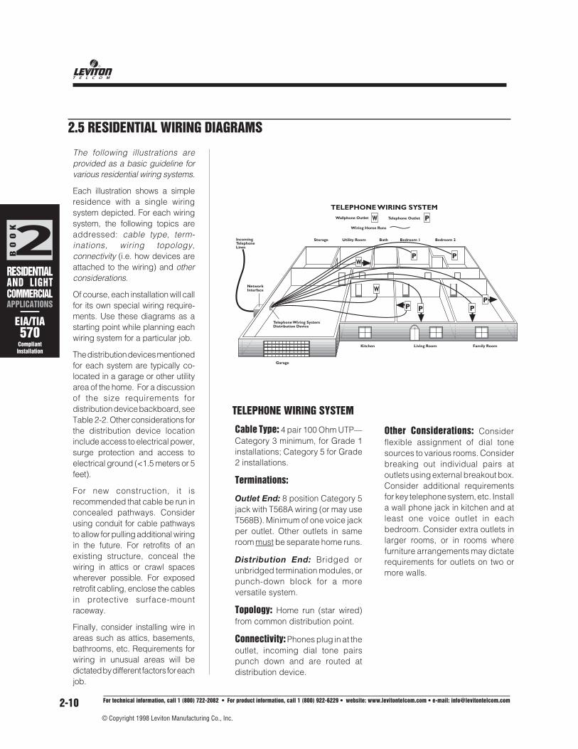
Cable Type: 4 pair 100 Ohm UTP—Category 3 minimum, for Grade 1installations; Category 5 for Grade2 installations.
Terminations:
Outlet End: 8 position Category 5jack with T568A wiring (or may useT568B). Minimum of one voice jackper outlet. Other outlets in sameroom must be separate home runs.
Distribution End: Bridged orunbridged termination modules, orpunch-down block for a moreversatile system.
Topology: Home run (star wired)from common distribution point.
Connectivity: Phones plug in at theoutlet, incoming dial tone pairspunch down and are routed atdistribution device.
The following illustrations areprovided as a basic guideline forvarious residential wiring systems.
Each illustration shows a simpleresidence with a single wiringsystem depicted. For each wiringsystem, the following topics areaddressed: cable type, term-inations, wiring topology,connectivity (i.e. how devices areattached to the wiring) and otherconsiderations.
Of course, each installation will callfor its own special wiring require-ments. Use these diagrams as astarting point while planning eachwiring system for a particular job.
The distribution devices mentionedfor each system are typically co-located in a garage or other utilityarea of the home. For a discussionof the size requirements fordistribution device backboard, seeTable 2-2. Other considerations forthe distribution device locationinclude access to electrical power,surge protection and access toelectrical ground (<1.5 meters or 5feet).
For new construction, it isrecommended that cable be run inconcealed pathways. Considerusing conduit for cable pathwaysto allow for pulling additional wiringin the future. For retrofits of anexisting structure, conceal thewiring in attics or crawl spaceswherever possible. For exposedretrofit cabling, enclose the cablesin protective surface-mountraceway.
Finally, consider installing wire inareas such as attics, basements,bathrooms, etc. Requirements forwiring in unusual areas will bedictated by different factors for eachjob.
2.5 RESIDENTIAL WIRING DIAGRAMS
TELEPHONE WIRING SYSTEM
NetworkInterface
Telephone Wiring SystemDistribution Device
Storage Utility Room Bath Bedroom 1 Bedroom 2
Garage
Kitchen Living Room Family Room
TELEPHONE WIRING SYSTEM
IncomingTelephoneLines
P P PP
PPW
W
Wallphone Outlet Telephone Outlet PWiring Home Runs
W
Other Considerations: Considerflexible assignment of dial tonesources to various rooms. Considerbreaking out individual pairs atoutlets using external breakout box.Consider additional requirementsfor key telephone system, etc. Installa wall phone jack in kitchen and atleast one voice outlet in eachbedroom. Consider extra outlets inlarger rooms, or in rooms wherefurniture arrangements may dictaterequirements for outlets on two ormore walls.

Wiring Strategies for Voice and Data Systems
2BOOK
RESIDENTIALAND LIGHTCOMMERCIALAPPLICATIONS
——EIA/TIA570
CompliantInstallation
© Copyright 1998 Leviton Manufacturing Co., Inc.
For technical information, call 1 (800) 722-2082 • For product information, call 1 (800) 922-6229 • website: www.levitontelcom.com • e-mail: [email protected] 2-11
NetworkInterface
Storage Utility Room Bath Bedroom 1 Bedroom 2
Garage
Kitchen Living Room Family Room
DATA WIRING SYSTEM
Data Wiring SystemDistribution Device
IncomingTelephoneLines
Data Outlet D Wiring Home Runs
DD D
D
DD
IncomingTelephoneLines
NetworkInterface
Storage Utility Room Bath Bedroom 1 Bedroom 2
Garage
Kitchen Living Room Family Room
BASIC AUDIO/VIDEO WIRING SYSTEM
SS
Audio/VideoWiring SystemDistribution Device
S
S S
S
In-Wall or Ceiling Speakers
Audio/Video Source Outlet AWiring Home Runs
Speaker Outlet Speaker Volume ControlS
A A
SS
DATA WIRING SYSTEM
Cable Type: 4 pair 100 Ohm UTP—Category 3 minimum for Grade 1installations, Category 5 for Grade2 installations.
Terminations:
Outlet End: 8 position Category 5jack with T568A wiring (or may useT568B). Minimum of one data jackper outlet. Other outlets in sameroom must be separate home runs.
Distribution End: Unbridgedmodule, Category 5 patch block(or Category 5 patch panel) orindividual Category 5 jacksmounted in a housing, bracket orpanel T568A wiring (or T568B maybe used). Wiring must match thewiring at the outlet.
Topology: Home run to commondistribution point (usually samearea as telephone wiring systemdistribution point)
Connectivity: Patch cords fromhub to panel/block/etc. atdistribution end; patch cords fromoutlet to data terminal networkconnection (i.e. the NIC card jack).
Distribution End: Varies depending onaudio/video distribution unit.
Topology: Home runs from potentialentertainment system locations to audio/video distribution unit. Home runs fromin-wall speakers, ceiling speakers, oraudio/video outlets via speaker volumecontrols to audio distribution unit. Audio/video wiring distribution point may beco-located with voice/data/videodistribution devices, or may be near theentertainment center location, or otherconvenient location as a sub-system.
Connectivity: Jumper cables fromoutlets to free-standing speakers and/orpatch cords and cables to audio/videocomponents. Wires terminate directlyinto audio/video distribution unit atdistribution end.
Other Considerations: The audio/videodistribution unit may be an electronicdevice which allows flexible assignmentof multiple sets of speakers to one ormore audio/video sources.
Other Considerations: Local AreaNetwork data hub mounts on wallnear distribution device. Install adata jack in each bedroom.Consider extra outlets in larger
rooms, in home office areas, or inrooms where furniture arrangementsmay dictate requirements for outletson two or more walls.
AUDIO/VIDEO(BASEBAND)SYSTEM WIRING
Cable Type: 2 or 4 conductorstranded, low-inductance audiowire per speaker–for high powerapplications. For low powerapplications, shielded, line levelcables of various types for audio/video signals.
Terminations:
Outlet End: Binding posts, bananajacks, RCAs or push/insert typeconnectors in wallplates.

ACHIEVING CATEGORY PERFORMANCE: Requirements Beyond Jacks & Cable
2BOOK
RESIDENTIALAND LIGHTCOMMERCIALAPPLICATIONS
——EIA/TIA570
CompliantInstallation
For technical information, call 1 (800) 722-2082 • For product information, call 1 (800) 922-6229 • website: www.levitontelcom.com • e-mail: [email protected]
© Copyright 1998 Leviton Manufacturing Co., Inc.
2-12
VIDEO (BROADBAND) SYSTEMWIRINGCable Type: RG6 Quad shield 75Ohm coaxial cable recommended.Two runs of coax to each TV outletlocation recommended (single runto front door camera location andother like locations; two runs to atticor roof for satellite). Also see “OtherConsiderations” below.
Terminations: Male F-typeconnector at both ends of cable.Threaded F-type fitt ings arerecommended to reduce noise.Push-on type F-fittings are notrecommended (except specialhigh-quality push-ons.)
Outlet End: Attached to the rearside of the outlet (which contains afemale-female F-type coupler).
Distribution End: Male F-typeConnector.
Topology: Home run to commondistribution point. This distributionpoint may be same area as voice/data wiring system distribution pointor may be the entertainment centerlocation (home theater room orfamily room, etc.)
Connectivity: At outlet end, coaxial75 ohm patch cords extend fromoutlet to video device (TV, VCR,etc.) At distribution end, male F-type connectors plug directly intovideo service unit, splitters, etc.
Other Considerations: A videoservice unit, splitter(s), and/oramplifiers may be located at thevideo wiring system distributionpoint. Utilize 75 ohm terminationcaps at idle outlets. In lieu of RG6coaxial cable, high-quality 100 ohmCategory 5 UTP cable may be usedfor video distribution with suitableadaptive devices. (Coax-to-UTP
converters may be required at bothends of each cable run.) Install avideo outlet in each bedroom.Consider extra outlets in largerrooms, or in rooms where videoequipment may have several locationoptions. Two runs of RG6 allow forvideo distribution from any videosource as well as distribution to a TVat each outlet location, and RG6 coax
NetworkInterface
Video Wiring SystemDistribution Device
Storage Utility Room Bath Bedroom 1 Bedroom 2
Garage
Kitchen Living Room Family Room
IncomingTelephoneLines
Coax Feed CATV,Satellite or Antenna
VIDEO WIRING SYSTEM(Home runs from common distribution point)
Wiring Home RunsVideo Outlet V
V V VV
VV
V
NetworkInterface
Storage Utility Room Bath Bedroom 1 Bedroom 2
Garage
Kitchen Living Room Family Room
Video Wiring SystemDistribution Device
VIDEO WIRING SYSTEM(Home runs from common entertainment center area)
IncomingTelephoneLines
VV
V
V
VV
Coax Feed CATV,Satellite, or Antenna
Video Outlet V Wiring Home Runs
V
may become a medium for data application.Another possiblity is that fiber optic cablemay eventually become a medium of choicefor some audio/video applications.

Wiring Strategies for Voice and Data Systems
2BOOK
RESIDENTIALAND LIGHTCOMMERCIALAPPLICATIONS
——EIA/TIA570
CompliantInstallation
© Copyright 1998 Leviton Manufacturing Co., Inc.
For technical information, call 1 (800) 722-2082 • For product information, call 1 (800) 922-6229 • website: www.levitontelcom.com • e-mail: [email protected] 2-13
Cable Type: Any copper comm-unication cable
Terminations: Loops terminateon connections in alarm panel.Alarm panel wires to an RJ31Xjack for incoming/outgoingsecurity line connections.
Topology: Daisy chain securityloops intercept all windows,external doors, motion detectorsand smoke detectors.
Connectivity: Connections tosensors, detectors, etc. arepermanent connections and willbe dependent upon the type ofdevide implemented.
Other Considerations: A touchpad, mounted in a convenientlocation is used to turn alarmsystem on/off or to set user
NetworkInterface
Storage Utility Room Bath Bedroom 1 Bedroom 2
Garage
Kitchen Living Room Family Room
Fiber Outlet
FIBER WIRING SYSTEM
F Fiber Home Runs
IncomingTelephoneLines
Fiber Wiring SystemDistribution Device
FF F
F
FF
IncomingTelephoneLines
NetworkInterface
Storage Utility Room Bath Bedroom 1 Bedroom 2
Garage
Kitchen Living Room Family Room
BASIC SECURITY WIRING SYSTEM
RJ31X Jack
SecuritySystemPanel
Motion Detector Wiring Home Runs
External Door orWindow Sensor Security Control KeypadSmoke Detector/
Rate of Rise Detector
programmable options. Note: Thisdiagram/description is provided asan example only. Please refer tosecurity system manufacturers’recommendations for cablingrequirements.
FIBER OPTIC WIRING SYSTEM
Cable Type: 2-strand, 62.5/125mmmultimode fiber optic cable.
Terminations: Two individual ST-type connectors (male) at eachend of cable or two individual SC-type connectors (male) at eachend of cable. These plug intowallplate-mounted couplings (2STs or duplex SC) at the outletend, and plug into panel mountedcouplings at the distribution end.
Topology: Home run (star-wired)from common distribution point(co-located at the data distributionpoint).
Connectivity: Fiber optic patchcords at both ends.
Other Considerations: Fiber opticapplications are not currently incommon use in the residential
market. Cabling with fiber, however,gives the user a versatile, high-bandwidth, cabling system that mayprovide much future capability. Asa cost savings, fiber optic cable isoften left unterminated. “Serviceloops” may be stored behind the
outlet wallplate, and at the fiberoptic wiring system distributiondevice. The fiber optic cable maybe terminated and mounted inwallplates and at the distributiondevice when needed.
BASIC SECURITY WIRING SYSTEM

BO
OK
TESTING &TROUBLE-SHOOTINGR E S I D E N T I A LAND LIGHTC O M M E R C I A LW I R I N GS Y S T E M S
2T
For technical information, call 1 (800) 722-2082 • For product information, call 1 (800) 922-6229 • website: www.levitontelcom.com • e-mail: [email protected]
© Copyright 1998 Leviton Manufacturing Co., Inc.
2-14
• Test equipment using visual indicators (coloredlights) or audible signals (beeps and tones) willsimplify the job and result in fewer errors andcallbacks. When test sets and troubleshootingprocedures are simplified, less experiencedpersonnel can do more dependable testing.
2T.1.1 TONE TEST SET ANDINDUCTIVE PROBE
These instruments are used together to identify whereparticular wires are located, broken, or terminated at anypoint along the horizontal run. A tone test set (Fig. 2T-1)generates a tone which is audibly detected by aninductive probe (Fig. 2T-2). The probe can detect thetones without actually connecting to the wires under test,which is very useful for tracing wire/cable circuits andlocating faults even through drywall or within large cablebundles. These tools provide more or fewer featuresdepending on the manufacturer and model.
Leviton's durable, low-costTone Test Set (Fig. 2T-1)provides the functions neededto isolate and test wiring invirtually any type of wireapplication including tele-phone, data, CATV, HVACsystems, and security/firealarm wiring. As a tonegenerator, the Tone Test Set can transmit either acontinuous 1000 Hz tone or an alternating 500/1000 Hztone for tracing pairs and locating broken pairs/cables inwalls. When connected across a wire pair, the tonegenerator signal allows the wire to be traced and isolatedby using Leviton's Inductive Speaker Probe (Fig. 2T-2).Note: When connecting to Category 5 wiring runs, thetoner leads should be attached to single wires in twoseparate pairs. The twisting on a single Category 5 pairwill attenuate the tone to the point that it cannot bedetected with the speaker probe.
The Tone Test Set also provides talk battery (forestablishing a communications line on an unused pair);tests for continuity; and checksfor shorts and opens. Inaddition, it identifies tip and ringpolarity, and clear, busy, andringing lines. A light-emittingdiode (LED) is used for all testindications.
2T
Testing cable runs is relatively simple—and is muchsimpler if done during rough-in, prior to installingdrywall. In addition, testing of runs prior to installingjacks or devices will prevent difficulty in isolatingthe fault. This section includes testing proceduresfor voice and security alarm systems.
WARNING! Disconnect electricalsources if at all possible before
performing tests. In the event thattelecommunications wiring has come incontact with power circuits, severe shockis possible. Check with a qualifiedelectrician if you are uncertain.
IMPORTANT: The testing of specializedcircuits for alarm systems requires specialconsiderations. Many alarm systems dependon proper polarity to operate, and it is essentialthat they be tested to assure that they will functionin the event of an emergency. Alarm systemsalso often depend on RJ31X-type USOC jackswith shorting bars to signal that the alarm systemhas been disconnected (tampered with).
IMPORTANT: Please read all cautions andwarnings on page 1-6.
2T.1 TOOLSUsing testing and troubleshooting equipmentspecifically designed for telephone installation andrepair will speed and simplify troubleshooting work.Many of the tests and procedures described in thisguide can be done with other less sophisticatedequipment not designed for the purpose. For example,troubleshooting and wiring verification involves detectionof continuity, voltage, and determination of polarity.While these tests can be accomplished using a volt-ohmmeter, it is easy to misinterpret a meter reading or toforget one test during a sequence repeated many timesduring a complex series of tests involving many differentconductors. Experience has shown that when substitutetest equipment is used, the procedures will take longer, beless reliable in finding the fault, and often will find only partof the problem.
!
TESTING & TROUBLESHOOTINGRESIDENTIAL & LIGHT COMMERCIAL LOW VOLTAGE WIRING
FIG. 2T-1. Tone Test Set.
FIG. 2T-2. Speaker Probe.

BO
OK
TESTING &TROUBLE-SHOOTINGR E S I D E N T I A LAND LIGHTC O M M E R C I A LW I R I N GS Y S T E M S
2T
Wiring Strategies for Voice and Data Systems
© Copyright 1998 Leviton Manufacturing Co., Inc.
For technical information, call 1 (800) 722-2082 • For product information, call 1 (800) 922-6229 • website: www.levitontelcom.com • e-mail: [email protected] 2-15
Some tests are accomplished using the tone test set byitself, while others require the use of the inductivespeaker probe. It is also possible to conduct these testsusing a lineman's test set instead of the probe.
Leviton's Inductive Speaker Probe is designed todetect audible tones to quickly trace and identify wiresor cables, without damaging the insulation. When usedin conjunction with a Tone Test Set, the Speaker Probeprovides the basic functions needed to trace and isolatepairs in virtually any type of wire application.
Often the installer needs to locate a pair within a cableor identify one cable from among many other cables ata terminal or behind wallboard where there is no easyaccess to bare connections. The Speaker Probe willallow tone to be detected without actually touching thetest leads to the conductor. The probe, sometimescalled a "banana" by telephone installers, will detect astrong tone several inches from the pair.
This device is a real time-saver when a large number ofcables or pairs (often several hundred) could possiblycontain the pair or cable you are trying to locate. Thesecable connections are usually terminated neatly on alarge backboard full of 66 blocks. You can quickly findthe pair with tone by moving the Speaker Probe alongthe pins of the block, if available, or by pulling eachcable slightly out of the bundle of cables and touchingthe probe to the outer jacket, listening for tone.
Leviton's Probe has a built-in amplifier and can be usedwith or without a lineman's test set. A lineman's test set,in the monitor position, permits listening without aid ofthe amplifier portion of the probe's circuitry. There areless expensive probes on the market that have noamplifier and must be connected to a lineman's test setfor use in tone locating.
Note that inductive speaker probes do not work withshielded twisted pair—the shield will block the tone,unless the toner is attached directly to an unterminatedshield.
2T.1.2 LINEMAN’S TEST SET (BUTTSET)Buttsets (so-calledbecause they are usedto 'butt-in' to a line)provide a means ofbridging onto wire pairsfor monitoring or dialing.Some models alsoprovide information onpolarity reversals andother faults.
Though not essential, Leviton recommends a lineman'stest set be used during premises wiring installation andrepair. An excellent choice is a line-powered unit (onethat uses no internal batteries). This type has been in useby telephone companies for many years. The test setshould signal with either rotary pulses or tone dialingmethods for use on any telephone circuit.
Some models have visual polarity test indicators builtinto the unit. These indicators show the presence ofvoltage and indicate proper or reversed (rolled) polarityon dial tone circuits or "dead" wiring systems under test,using a battery power source. Switches permit monitoringor talking on active pairs as well as switching in and outof the test set's network and keypad components forspecial tests.
2T.1.3 TIME DOMAIN REFLECTOMETERS(TDR'S)
Time Domain Reflectometer (TDR) instruments use radar-like principles to detect the existence and location ofcable faults. The signal it sends down a suspect cable isreflected back to the test instrument, where theinformation is displayed for the user to interpret.
There are two important things to remember when usinga TDR. First, a quality connection between the cable andthe TDR is vital, as TDR signals contain high frequencycharacteristics that are not efficiently transmitted throughpoor connections or inadequate test leads. A loose orsloppy connection can cause misinterpretation and othererrors.
Second, it is crucial to enter the correct VOP data (speedat which a signal travels down the particular type ofcable being tested; consult the man-ufacturer’sinstructions). As with all equipment, a TDR reading willonly be as accurate as the operator and the instrumentsettings permit it to be.
2T.1.4 MODULAR BREAK-OUT ADAPTERSA modular adapter provides a convenient way to cliponto the individual pins of any 6- or 8-position modularjack or plug. Various styles exist: some break all leads ofthe jack out into flat conductorsthat alligator clips can be clippedonto, and some have a means ofswitching between pairs.
FIG. 2T-4. Modapt.
FIG. 2T-3. Buttsets.

BO
OK
TESTING &TROUBLE-SHOOTINGR E S I D E N T I A LAND LIGHTC O M M E R C I A LW I R I N GS Y S T E M S
2T
For technical information, call 1 (800) 722-2082 • For product information, call 1 (800) 922-6229 • website: www.levitontelcom.com • e-mail: [email protected]
© Copyright 1998 Leviton Manufacturing Co., Inc.
2-16
!
2T.2. ROUGH-IN WIRING TESTS• Never begin installation of telephone wiring
devices on a roughed-in job until the rough-inwiring has been tested for shorts, grounds, andopens. When starting with a verified rough-intelephone wiring system, it is possible with propermethods to detect an error in device wiring at thetime the error is made. This way, if device installationis completed and a problem shows up, it is likely thatthe fault lies in the device termination rather than withthe building wiring.
• Failure to install proper wiring and devices beforeoccupancy can also cause serious disagreementsand builder or homeowner dissatisfaction. Theseproblems often arise when the occupant requestsadditional lines from the exchange carrier, only to betold the wiring is inadequate or "defective." Avoidthese disputes by using proper materials andmethods in the first place.
Some sophistication is required when troubleshootingtelephone wiring systems because there are many waysproblems can be created if the multi-color codedconductors are not properly matched, and devices notcorrectly wired. Polarity must always be observed,especially when making the transition from one colorcode to another. Most electrical house wiring problemsshow up immediately with a blown fuse or activatedcircuit breaker—but many telephone wiring systemproblems do not show up immediately, and often seemto get more complicated if repairs are attempted byuntrained persons.
• Always use proper materials to prevent trouble.The best wire choice is UL listed, NEC Article 800compliant, four twisted-pair jacketed inside wire.Quad wire (pairs not individually twisted) is generallynot suitable because it is only designed to carry oneanalog voice circuit (the other two wires are forground and accessory functions). Thus Quad wireshould not be used with multiple lines, key systems,PBX systems, digital phone sets, or data applications.
• Perform the following tests for each pair, afterhaving made sure that the system is not connectedto the network (“pull the plug” at the demarcationpoint first) or, more accurately, do not connect to thenetwork prior to completely installing and testing allcomponents.
• In commercial applications, test horizontal runsprior to cross-connecting at the telecomm-unications closet, if one is present.
WARNING: Hazard of Electric Shock.These tests are not intended for use
on energized wiring or circuits. To avoid electricshock, disconnect all sources of electric currentbefore testing. If you are unfamiliar with electricalwiring, consult a qualified electrician or otherprofessional. Check local codes or otherrequirements before working on electrical orcommunications wiring circuits.
2T.2.1 BASIC TESTING BEFORE TRIM-OUT1. Do a visual inspection of wire color matching to
assure that the right access line is assigned to theright set of pairs, and that Tip (+) and Ring (-) areassigned to the proper pins.
2. Next, test each pair for a) continuity, b) shorts toground, c) shorts to other pairs (“crosses”)d) reversed polarity (“roll”). See Fig. 2T-5.
See section 3T for testing Category 5 wire.
2T.2.2 USING A BATTERY AND VOLT-OHMMETER (RESIDENTIAL):
1. Find a reliable ground connection, and check eachlead at each outlet for a short(s) to ground. Thereshould be no continuity between any of the leadsand earth ground.
2. Assure that the network is disconnected. Thenconnect the battery across the Tip and Ring leads ofeach pair at the closest point available to thedemarcation point, but not on the network side.Connect the positive side to Tip and the Negativeside to Ring.
3. Go to each outlet and perform the following testswith the volt-ohm meter for each pair:
3a. Verify that the polarity of each pair is correctwith Tip at positive voltage and Ring atnegative.
3b. Verify that there is no continuity with any otherpair at the outlet by checking the Tip leadagainst all other leads, and then the Ring leadagainst all other leads.

BO
OK
TESTING &TROUBLE-SHOOTINGR E S I D E N T I A LAND LIGHTC O M M E R C I A LW I R I N GS Y S T E M S
2T
Wiring Strategies for Voice and Data Systems
© Copyright 1998 Leviton Manufacturing Co., Inc.
For technical information, call 1 (800) 722-2082 • For product information, call 1 (800) 922-6229 • website: www.levitontelcom.com • e-mail: [email protected] 2-17
2. Then short the far end by metallic means. The testerwill light the appropriate LEDs to indicate properpolarity. (A toner and probe can be used to identifythe proper cable, if necessary.)
Note: This part of the test is usually not performed inhigh-volume commercial installations.
2T.2.4 USING A TONE GENERATORAND INDUCTIVE PROBE
These tools are used together in identifying one specificpair from others. The tone generator (toner) is attachedto one end of a vacant pair which must be traced to findthe location of a fault, or identified so it can be spliced fora new circuit; then the probe is used to "pick up" the tone,tracing the tone signal either along the wire or at the otherend. For this test it is assumed that a continuity tester hasalready been used to verify continuity, polarity, and lackof shorts, yet a fault still exists.
1. Connect the toner to the leads at the outlet.
2. Take the probe to the distribution device ortelecommunications closet. When the probe is heldnear the pair carrying tone, the tone will be quitestrong. (Some lesser volume may be picked up onadjacent leads or pairs, but this is normal.)
• The pair carrying tone can be verified by touchingthe tip of the probe across the leads. The tones willcease if that pair is the one carrying the tone.
• At this point, assuming the continuity tests showedno faults, the leads are normally “punched down” incommercial applications. In residential applicationsthey may already have been terminated at thedistribution device.
3. With the toner still on at the outlet, a buttset can beconnected across the pair. The impedance of thebuttset provides additional information. It shouldpick up the tone, which should be relatively loud. Ifthe tone is faint, an open (break) in the circuit is likely.If the tone is not heard at all with the buttset, the likelyfault is a short.
4. In Commercial applications, an earth ground point isavailable in the telecommunications closet. Test forshorts to ground by attaching one lead of a continuitytester to that ground and running the other lead downthe clips of the punchdown block (assuming theclips are accessible). In this manner the test forshorts to ground can be made after the leads areterminated.
CROSS
ROLL
MARKED TIP (ACTUALLY RING)TIP
RING
MARKED RING (ACTUALLY TIP)
GROUNDFAULT
COMMON WIRING FAULTS
CLEAN OPEN FAULT
DIRTY OPEN FAULT (INTERMITTENT)
SHORT (CONTINUITY)
SPLIT TIP
RINGRINGSPLIT
SPLIT TIP
RINGRING
TIP (2ND PAIR)
TIP (1ST PAIR)
FIG. 2T-5. Common Wiring Faults.
2T.2.3 USING A SPECIALIZED CONTINUITYTESTER
Most continuity testers provide one or more LEDs toindicate shorts, opens, and polarity. The tester providesbattery voltage and if a short exists, the appropriate LEDwill light.
1. With the leads unterminated at either end, connectthe continuity tester across the leads of each pair insuccession. Test also at the outlet for continuitybetween the Tip lead of each pair with all other leads,and then the Ring lead with all other leads, to assurethat there are no shorts to them.

BO
OK
TESTING &TROUBLE-SHOOTINGR E S I D E N T I A LAND LIGHTC O M M E R C I A LW I R I N GS Y S T E M S
2T
For technical information, call 1 (800) 722-2082 • For product information, call 1 (800) 922-6229 • website: www.levitontelcom.com • e-mail: [email protected]
© Copyright 1998 Leviton Manufacturing Co., Inc.
2-18
• If a cross is located before any devices are installed,it is likely that a nail or other fastener has been driveninto the roughed-in wiring. Before the wiring can becompleted, a cross must be located and repaired, orisolated out of the system.
2T.2.7 TESTING FOR SPLITSA split occurs when two wires of a pair are split (separated)and improperly matched with wires from another pair (forexample, tip lead of pair #1 mated with ring lead of tip#2). A split will normally be located during the tests foropens and continuity previously described. Splits mostoften occur during splicing operations in low light, orwhen the splicer is tired or distracted.
1. Connect the tone test set in the TONE mode to thetwo wires in one pair at the end of the cable.
2. Using the speaker probe, trace the tone along thecable pairs to the splice location. Once there, identifythe wires you believe are the pair of interest, and usethe probe tip to short these two wires.
• If the pair is split, the tone will remain strong when thewires are shorted.
• If the pair is straight (not split), the tone will disappearwhen the wires are shorted.
Splits can also be isolated using a lineman's test set withthe Tone Test Set. Refer to your lineman's test setinstructions for details.
2T.2.8 TESTING FOR REVERSED POLARITY(ROLLS)
A rolled pair results when the tip and ring leads arereversed in connecting to the network. This may be donewhile splicing or installing a device. Proper polarity isessential for proper operation of some tone dials. A rollwill not affect rotary dialing.
If a true tone telephone set does not produce tonebeeps when the keypad is pushed, polarity may bereversed. If changing the polarity causes the set tobeep as the keys are pushed, but numbers are notdialed (i.e., dial tone stays on), then the central officeis not equipped to provide touch dialing on thatparticular line. Some telcos charge a monthly fee toprovide touch dialing capability on a line; if the fee isnot paid, they may inhibit tone dialing electronically.
2T.2.5 TESTING FOR SHORTS AND OPENS(CONTINUITY)
The continuity setting of the Tone Test Set is used tolocate shorts and verify continuity (no opens). A full shortis indicated with a continuously lit green LED. A resistiveor dirty open condition is indicated by a dim or blinkingLED.
1. Locate and identify each pair on both the outgoingand incoming roughed-in wiring.
2. Test the tester (to verify it is operational) by touchingthe leads together and looking at the LED for indicationof a full short (steady LED).
3. Connect the test set leads to the outgoing pair(polarity does not matter here) and set the test setswitch to CONT. There should be no indication ofcontinuity until the same pair on the incoming (returnfeed) is shorted. Any continuity indication beforeshorting the return feed pair means there is a faultwithin the pair (or multiple grounds). Only when thereturn feed is shorted should there be a solid shortindicated by a continuous unchanging LED like yousee when shorting the leads of the tone test set.
• If the LED is dim or blinking, there is a resistance orintermittent fault in the pair. Poor splicing or corrodedsplices will result in a high-resistance loop. Theresistive connection or splice must be located withthe probe, and corrected using a splicing tool, beforeconnecting the circuit. Dial tone connections to aresistive loop will result in static noise, poor dialingand ringer operation, and low loop current.
2T.2.6 TESTING FOR CROSSESA cross is a common fault caused by sloppy devicewiring which allows a short to develop between twoterminals. Usually this occurs because too much barecopper conductor is stripped and then the tail is nottrimmed after connection.
Testing for crosses involves using the continuity mode ofthe toner to locate any electrical path from eitherconductor of one pair to either side of another pair. Thisis done as follows:
1. Attach one test set clip to the tip side of a pair (this isyour fixed lead). Using the other lead, check forcontinuity to both sides of every other pair.
2. Next, change the fixed lead to the ring side of thesame pair and repeat Step 1.
3. Repeat this sequence for each pair. If there is anycontinuity indication, a cross is present in the wiring.

BO
OK
TESTING &TROUBLE-SHOOTINGR E S I D E N T I A LAND LIGHTC O M M E R C I A LW I R I N GS Y S T E M S
2T
Wiring Strategies for Voice and Data Systems
© Copyright 1998 Leviton Manufacturing Co., Inc.
For technical information, call 1 (800) 722-2082 • For product information, call 1 (800) 922-6229 • website: www.levitontelcom.com • e-mail: [email protected] 2-19
If a push button set produces dial pulses when thekeypad is operated, the set is not really a tone set. It maybe called a "universal dialing set" but it does not signalto the central office with tones. When the keypad isoperated, numbers are pulsed out just like a standardrotary dial. This type of set is easily identified by theletters "TE-R" (Terminal Equipment-Rotary) as the lastthree items in the FCC registration number printed on alabel attached to the telephone. If the last three lettersare "TE-T" (Terminal Equipment-Tone), then the set is a"true tone set" that signals the central office with tonesinstead of rotary dial pulses.
The Leviton Tone Test Set is equipped for polarity testingwith a visual indicator. If dial tone is connected to the pairunder test, the presence of a roll can be detected asfollows:
1. With the test set in the OFF position, plug in the tonetest set with the modular connector.
2. Observe the LED. A green LED indicates correctpolarity; red means reversed polarity (a 'roll').
• If this polarity test is performed with the tonerconnected to a pair using the test clips insteadof the modular plug, you must be certain youare connecting the leads to the properconductor. Tip is normally positive (connect theblack lead) while ring is normally negative (connectthe red lead).
• If using central office battery (dialtone) for this test,you must be sure to check polarity during the dialtoneBEFORE a number is dialed. Polarity will sometimesbe reversed by the central office during completionof a call.
Some people prefer to test polarity with a buttset andtone test set, without dialtone connected. There areseveral methods that will work. The first method uses thetwo test devices together:
1. Switch the Leviton tone test set to the CONT position.In this setting, the battery inside the unit is connectedto the test leads. Connect the red test lead to ring,and the black lead to tip of the pair under test.
2. Clip on the buttset with the switch in the monitorposition. Be sure to observe polarity when connectingthe buttset (red lead to ring, black to tip). Indicatorson the buttset will show voltage is present and thereis proper polarity (refer to your buttset instructions fordetails).
3. Using a modular breakout adapter, you can plugdirectly into each device and connect the buttsetleads to the adapter.
Some installers prefer to use a 12-volt lantern battery asthe source:
1. Simply plug the tone test set directly into eachmodular jack, instead of using a modular adapterand the buttset clip leads.
2. If polarity appears reversed at ALL devices, firstcheck the network polarity at the demarc jack. Thencheck at the common connecting point to see if theroll is there, affecting all devices. If the roll appearson ALL devices beyond a certain point, check thecontinuing connections at the device just before thatpoint. If only one device shows a roll, the problem isprobably in the connection of that single jack.
• If you discover the pair rolled on the network side,report the problem to the utility. Do not reverse theinside wiring system to accommodate a networkreversal—the network error may be detected at anytime and "made normal." This would reverse yourconnection again, resulting in a callback.
2T.3 FINAL VERIFICATION TESTING
2T.3.1 BASIC RESIDENTIAL WIRINGVERIFICATION
After the jack has been installed in the outlet, andassuming all other prior tests were successful, finalverification testing can be performed with a simpletelephone set or a buttset—if dialtone service has beeninstalled. Splitting adapters can be used where necessaryto test for multiline service.
1. Connect to the NID (network interface device) at the demarcation point.
2. Go off-hook and receive dial tone.
3. If a test number is available, make a call to it andreceive a return call. (Check with the local telephonecompany about test lines.) Listen for cleartransmission without pops, clicks, or scratchingsounds. Your office may be able to assist if a testnumber is not available. In any case, assure thatdigits dialed will stop dial tone, and that dial toneresumes when the phone is hung up and then takenoff hook again.
• If these tests fail, either the line has not been installed,or the fault is in the access lines to the phonecompany, in which case the phone company shouldbe contacted.

BO
OK
TESTING &TROUBLE-SHOOTINGR E S I D E N T I A LAND LIGHTC O M M E R C I A LW I R I N GS Y S T E M S
2T
For technical information, call 1 (800) 722-2082 • For product information, call 1 (800) 922-6229 • website: www.levitontelcom.com • e-mail: [email protected]
© Copyright 1998 Leviton Manufacturing Co., Inc.
2-20
4. Repeat the tests for each of the lines at thedemarcation point.
5. Connect the NID to the premises wiring.
6. Go to each outlet in turn and repeat the test for everyinstalled line (at each jack). If a failure is encountered,proceed as follows:
• Check the connections to the jack for properconnections and check the wiring (including thedistribution device and any auxiliary disconnects) tosee if any obvious disturbance has occurred sincerough-in. Some phones may not work with polarityreversed, so be particularly careful to check wirecolors for proper polarity.
• If no fault is obvious, re-test as for rough in.
NOTE: If dial tone service is not available, perform the sametests as for rough-in before the jacks were installed. Asplitting adapter may be necessary to test each line of eachjack. A toner may be used with a normal telephone orbuttset to test for dial tone. Most toners will provide anaudible tone to the phone as well as sufficient voltage topower the phone to generate touch-tone or rotary dialdigits.
2T.4 TESTING SECURITY SYSTEMSSince FCC Docket 88-57 permits non-carriers to connectwiring and other devices to the carrier’s network (on thecustomer’s side of the demarcation point) there is anexpanded opportunity for those involved in securitysystems installation and maintenance. This alarm systemtroubleshooting section will describe how to use Levitontest equipment to:
• Verify correct installation and operation of alarm andphone system wiring and RJ-31X exclusion-type“dialer jacks,” with or without Telco dialtone available.
• Locate and troubleshoot wiring for proper installationof RJ-31X jacks.
• Locate and identify spare pairs in existing premisewiring to facilitate initial alarm installations.
• Locate and use spare wire pairs in establishingalarm systems for more economical upgrades andexpansion.
For Commercial /Category 5 WiringVerification, see Book 3T.
IMPORTANT: The testing of specializedcircuits for alarm systems requires specialconsiderations. Many alarm systems dependon proper polarity to operate, and it is essentialthat they be tested to assure that they willfunction in the event of an emergency. Alarmsystems also often depend on RJ31X-typeUSOC jacks with shorting bars to signal that thealarm system has been disconnected(tampered with).
CAUTION: You may not access, attach, ormodify any wiring attached to the protectoror on the carrier’s side of the demarcationpoint, as this would be in violation of FCC rulesand regulations. If you have questions aboutthe installation of jacks or other equipment at acustomer location, Leviton suggests that youcontact the carrier company servicing thatcustomer. Often details are provided in the firstfew pages of your local phone directory.
2T.4.1 TESTING SECURITY SYSTEMS FORSHORTS AND OPENS (CONTINUITY)
1. With the tone test set mode switch set to CONT,connect the red and black test leads of the Tone TestSet to the loop wires under test.
• Polarity does not matter in this test. A solid green LEDlight indicates a closed circuit, a dim LED indicatesoff hook status, and a pulsing LED indicates aringing line. If the LED does not light, check foropens in the loop.
2T.4.2 LOCATING SECURITY LOOP FAULTSUse Leviton’s Tone Test Set and Speaker Probe toquickly check for opens, faulty active devices, anddamaged contacts or switches. These test sets can alsolocate poor or corroded splices or connections, and foilbreaks in the protective circuit, without disturbing anyfield wiring connections.
1. Clip the Tone Test Set’s red lead to either side of theloop while it is disconnected from the alarm panelterminals, and select the TONE position (see Fig.2T-6).
Note: For this test to be accurate, attach only one leadto the loop.
2. Then, with the Speaker Probe, listen at the splice locations for a tone.

BO
OK
TESTING &TROUBLE-SHOOTINGR E S I D E N T I A LAND LIGHTC O M M E R C I A LW I R I N GS Y S T E M S
2T
Wiring Strategies for Voice and Data Systems
© Copyright 1998 Leviton Manufacturing Co., Inc.
For technical information, call 1 (800) 722-2082 • For product information, call 1 (800) 922-6229 • website: www.levitontelcom.com • e-mail: [email protected] 2-21
• If no tone is heard, then the wiring break is somewherebetween that point and the panel.
• If a tone is heard, continue probing the wiring untilthe tone is lost or greatly attenuated. When the tonediminishes or disappears entirely, a fault is indicatedbecause the signal is no longer carried by the loopcircuit.
If the fault is caused by improperly spliced or crimpedwire connection, a clean, reliable splice is achieved byusing a dedicated splicing/crimping tool.
2T.4.3 LOCATING SPARE PAIRSInstalling or upgrading phone and alarm systems iseasier and more economical if existing wiring can beused. Use the Speaker Probe and Tone Test Set to traceand identify spare pairs in existing premise wiring.Leviton’s Tone Test Set and Inductive Speaker Probeare ideal tools for rapidly troubleshooting alarm systems.
• For instructions on locating spare pairs bytracing tone, see Section 2T.2.4.
2T.4.4 TROUBLESHOOTING THE RJ-31XThe RJ-31X exclusion-type “dialer jack” (Fig. 2T-7) iscommonly used with security and fire alarm equipmentto provide exchange access lines to alarm reportingdevices. The phone line is wired in series through theRJ-31X; from there, tip and ring pass through the dialer.A normally closed relay will open if the alarm is activated,seizing the circuit for alarm use, while temporarilydisconnecting house phones to avoid disruption of thedialing sequence.
The eight-position, non-keyed miniature jack has shortingbars across terminals 1-4 and 5-8. Inserting the modularplug lifts the contact wires away from the shorting bars,extending the tip and ring circuit to the series leadsgoing into the alarm device. When the plug is removedfrom the jack, metal tabs inside the RJ-31X providedirect connection of tip and ring back to the otherlocations, bypassing the alarm device. This design letsthe dialer control the line for exclusive use when in alarmmode. It also permits “phone trouble” to be isolated byunplugging the panel/dialer to route tip and ring directly tohouse phones.
Some technicians may install a “shortcut” or de-populated four-terminal version of the dialer jack. Inthe shortcut dialer jack, the jumpered terminals whichsupervise the presence of the plug are missing.Consequently, the depopulated version cannot providea hard-wired, normally closed tamper loop for supervising
DIALER OR COMMUNICATOR
PANEL
NC SPACE COVERAGE
DEVICE NC DOOR SWITCH
NC DOOR SWITCH
1K RESISTORIN SERIES
LEVITON TONE TEST SET
TYPICAL NORMALLY CLOSED BURGLAR ALARM LOOP
PLACE A 1K RESISTOR IN SERIES WITH THE TONE TEST SET AND THE LOOP. THIS WILL ATTENUATE THE SIGNAL AND PROVIDE BETTER ACCURACY IN LOCATING A BREAK IN THE LOOP. SHORTER LOOPS MAY REQUIRE A HIGHER VALUE SERIES RESISTOR.
TO TELCO OR LOCAL ALARM
CLIP
CLIPALARM
the presence of a modular plug in the jack. If the tamper/trouble indication function is important to your customer,be sure to install a fully populated RJ-31X jack, andproperly connect all terminals.
Leviton recommends that the RJ-31X be installed in frontof any other jacks in the system so that when an alarmoccurs, the automatic dialing unit will take priority andseize the line, leaving all house phones and wiringdisconnected.
Unless noted otherwise, the tests described in thissection require that Telco dialtone be available.
2T.4.5 VERIFYING RJ-31X INSTALLATIONWith the Tone Test Set switch in the OFF position,connect the tone set leads to terminals 4 (ring) and 5 (tip)of the RJ-31X jack. (See Fig. 2T-7, Test 1.) The LEDshould glow bright, steady red, indicating voltage issupplied to the line and dialtone is available. A greenLED indicates the line is off hook, and a pulsing orangeLED indicates a ringing line.
2T.4.6 VERIFYING RJ-31X WIRING WITHOUTDIALTONE.
If installation occurs before dialtone is connected, it isespecially important to check the panel, dialer, and jack
FIG. 2T-6. Locating Security Loop Faults

BO
OK
TESTING &TROUBLE-SHOOTINGR E S I D E N T I A LAND LIGHTC O M M E R C I A LW I R I N GS Y S T E M S
2T
For technical information, call 1 (800) 722-2082 • For product information, call 1 (800) 922-6229 • website: www.levitontelcom.com • e-mail: [email protected]
© Copyright 1998 Leviton Manufacturing Co., Inc.
2-22
wiring to make certain both alarm and phone will workproperly when dialtone is supplied. Note: Without Telcodialtone, polarity cannot be verified, but Telco standardpolarity color coding is shown in Fig. 2-2 on page 2-2.Telco installers will observe this color code whenconnecting dialtone.
1. With the Tone Test Set switch set to TONE, connectthe test set leads to terminals 4 (ring) and 5 (tip) ofthe RJ-31X jack (see Fig. 2T-7, Test 2). Be sure toobserve proper polarity.
2. Trace the generated tone through the entire circuitwith the probe. Tone should be heard throughout.
3. Then, to verify the operation of the alarm dialer, setthe alarm panel off and check the house phonewiring with the probe. No tone should be heard onthe house wiring. This indicates that the dialer hasseized the line.
2T.4.7 VERIFYING POLARITY TO THEPREMISE PHONE SYSTEM
It is important for the alarm installer to verify correctpolarity to the premise phone line, especially in old tonetelephone systems without polarity guard. In such asystem, if tip and ring are reversed and an emergencyoccurs, the alarm may or may not work, and the phonewill not dial out.
1. With the alarm panel in normal, connect the ToneTest Set red lead to terminal 1 (ring) and the blacklead to terminal 8 (tip). (See Fig. 2T-7, Test 3.)
• If dial tone is connected to the pair under test, the rollis indicated by the LED. A green LED indicatesproper polarity while a red LED indicates 'rolled' orreversed polarity. For more information about polaritytesting, see section 2T.2.8.
FIG. 2T-7. RJ-31X Jack Wiring Diagram
TO TELCO
(RING) (TIP)
RJ-31X JACK
JUMPER
TESTS 1 & 2
BLACK TIPRED RING
TEST 4
RED LEADBLACK LEAD
TO HOUSE PHONES
MODULAR PLUG
SILVER SATIN CORD
REDGREENBLACK
BRN/BLKGRY/WHTYELLOW
TEST 3
BLACK TIPRED RING
TAMPER/TROUBLE INDICATOR
DIALER OR COMMUNICATOR PANEL
TO BURGLAR LOOP
RING
TIP
LOOP
R1
T1
4
3
2
1
5
6
7
8
2T.4.8 VERIFYING THE SECURITY SYSTEMTAMPER LOOP
Most alarm systems have a trouble/tamper indicator toalert the owner when the system cannot arm because thealarm’s modular plug has been disconnected. Only afully-populated, eight-terminal jack can provide asupervisory circuit. The tamper loop is a normallyclosed circuit, jumpered at terminals 3-6, that opensupon removal of the plug. Alarm installers can use thetoner to verify the tamper loop and ensure that the systemwill be able to detect this condition.
1. With the Tone Test Set switch set to CONT, connectthe test set leads to the black and yellow wires in thealarm control box (Fig. 2T-7, Test 4).
2. Unplug and replug the modular jack several times toverify that the trouble indicator lights up when themodular jack is removed.
• Remember, this test cannot be performed with the“shortcut” version of the RJ-31X.

BO
OK
TESTING &TROUBLE-SHOOTINGR E S I D E N T I A LAND LIGHTC O M M E R C I A LW I R I N GS Y S T E M S
2T
Wiring Strategies for Voice and Data Systems
© Copyright 1998 Leviton Manufacturing Co., Inc.
For technical information, call 1 (800) 722-2082 • For product information, call 1 (800) 922-6229 • website: www.levitontelcom.com • e-mail: [email protected] 2-23
CATEGORY 5 CABLE TESTERS – MANUFACTURER LISTINGTo ensure Category compliance of installed wiring, a hand-held cable tester should be used. Thefollowing companies manufacture hand-held Category 5 cable testers. This information is listed asa courtesy for your reference only and is not an endorsement nor a recommendation. You areadvised to contact each company directly to request detailed information about each product.Some of these companies also sell their product through other companies under other productnames; you are advised to ask which of these companies is the actual manufacturer of the tester.
Datacom Technologies Product11001 31st Place West LANcat® Installer Cable Tester, LANcat® System 5Everett, WA 98204 Cable Tester and Talk Set, Optical Loss Measuring800-468-5557 System LANcat® System 6 Cable Tester425-355-0590 and Talk Set, FIBERcat™
Fax: 425-290-1600www.datacomtech.com (website)[email protected] (email)
Fluke Corporation ProductP.O. Box 9090, MIS 250E DSP-100 CableMeter, DSP-100/SR Cable MeterEverett, WA 98206 DSP-2000 CableAnalyzer, DSP-FTK Fiber Test800-44-FLUKE (Customer Support) Kit (MM), LS-1310/1550 Fiber Test Kit (SM)www.fluke.com/nettools/ (website) Fluke 140 Tone Probe & Fluke 620 LAN Cable Meter
Microtest, Inc. Product4747 North 22nd Street PentaScanner 350Phoenix, AZ 85016-4708 PentaScanner 8150-00800-526-9675602-952-6400Fax: 602-952-6401www.microtest.com (website)[email protected] (email)
Scope Communications, Inc. Product753 Forrest Street Wirescope 155 Cable Analyzer, Part No. 500-5200Marlborough, MA 01752 Fiber SmartProbe+, Part Number 500-5265800-418-7111508-786-9600Fax: 508-786-9700www.scope.com (website)[email protected] (email)
Wavetek Product9145 Balboa Ave LT 8000, LT 8100, LT 8155San Diego, CA 92123800-854-2708619-279-2200Fax: 619-627-0132www.wavetek.com (website)

BO
OK
TESTING &TROUBLE-SHOOTINGR E S I D E N T I A LAND LIGHTC O M M E R C I A LW I R I N GS Y S T E M S
2T
For technical information, call 1 (800) 722-2082 • For product information, call 1 (800) 922-6229 • website: www.levitontelcom.com • e-mail: [email protected]
© Copyright 1998 Leviton Manufacturing Co., Inc.
2-24
NOTES

3-1
Wiring Strategies for Voice and Data Systems
3BOOK
C O P P E RCABLING FORCOMMERCIALAPPLICATIONS
——TIA
568-ACompliantInstallation
© Copyright 1998 Leviton Manufacturing Co., Inc.
For technical information, call 1 (800) 722-2082 • For product information, call 1 (800) 922-6229 • website: www.levitontelcom.com • e-mail: [email protected]
3.1 BENEFITS OF TIA-568-ACOMPLIANCE
Commercial building horizontal cabling that is installedin accordance with the TIA-568-A standard is like havingone type of foundation that can support any type ofstructure that is built upon it—even if the structure keepschanging. The benefits are that you have one systemwhich will:
a) Simplify ongoing maintenance, relocation, andaddition;
b) Accommodate future equipment and servicechanges;
c) Accommodate a diversity of user applications,including voice, data, LAN, switching, and otherbuilding services.
3.1.1 STAR TOPOLOGYTIA-568-A specifies a star topology: a hierarchicalseries of distribution levels. In the backbone are themain distribution frame (MDF) and the optionalintermediate distribution frame (IDF). Only one IDF isallowed between the MDF and telecommunicationscloset.
In addition to the installation practices for Residential andLight Commercial buildings in Book 2, the practices inthis section should be followed in order for a horizontalcabling installation in Commercial buildings to complywith TIA-568-A.
IMPORTANT: Please read all warnings andcautions on page 1-6.
Scope: This Guide only covers horizontal cabling, notbackbone cabling. Backbone cabling for the MDF, IDF,Equipment Room and Telecommunications Closet isbeyond the scope of this document. This is due to thefact that backbone cabling in TIA-568-A is veryapplication and building specific, and dependent uponthe type of communications, type of building, and manyother issues. Thus for backbone and crossconnect designand installation the user is cautioned to refer to the TIA-568-A standard document and if necessary,communications consultants. But in general, thespecifications for backbone wiring are:
• a maximum of two levels
• star topology
• limited to 90 meters for Category-ratedapplications; 800 meters for voiceapplications.
Horizontal cabling in TIA-568-A, on the other hand, is ageneric cabling system. If horizontal cabling is installedaccording to the practices in the standard, the systemwill be sufficient for the majority of applications for whichit will be used.
For the purposes of this section, horizontal cabling isconsidered the cabling from the work area to thetelecommunications closet. It includes thecrossconnects in the telecommunications closet;horizontal cable; and the outlet at the work areas.
Note on Scope Of TIA-568-A: TIA-568-A covers onlythe building's cabling systems, not the pathways suchas conduit or raceways. Commercial building pathwaysand spaces for telecommunications wiring are coveredin a separate standard, TIA-569. Grounding is coveredin TIA-607.
INSTALLATION PRACTICES FOR COMMERCIAL BUILDINGS(TIA-568-A COMPLIANCE)
3
FIG. 3-1. Typical Commercial Building Wiring Topology
EQUIPMENTROOM(S)
TELECOMMUNICATIONSCLOSETS (AND/ORINTERMEDIATEDISTRIBUTION FRAMES)
HORIZONTAL WIRING (PATHWAYS)FROM THE TELECOMMUNICATIONSCLOSET TO THE INDIVIDUALWORKSTATIONS
BACKBONEWIRING
SERVICEENTRANCE
ENTRANCEROOM
INTERBUILDINGBACKBONEWIRING
MAINDISTRIBUTIONFRAME
WS
WS
WS WS
WS
WS
WSWS
WS

3-2
3BOOK
C O P P E RCABLING FORCOMMERCIALAPPLICATIONS
——TIA
568-ACompliantInstallation
For technical information, call 1 (800) 722-2082 • For product information, call 1 (800) 922-6229 • website: www.levitontelcom.com • e-mail: [email protected]
© Copyright 1998 Leviton Manufacturing Co., Inc.
Figure 3-2. Typical Commercial Wiring Topology.
BUILDING 2
BUILDING 3
X
EF
ER
IC
MC
LEGENDCROSS-CONNECT
ENTRANCE FACILITY
EQUIPMENT ROOM
INTERMEDIATE CROSS-CONNECT
MAIN CROSS-CONNECT
MECHANICAL TERMINATION
SPLICE
TELECOMMUNICATIONS CLOSET
TELECOMMUNICATIONS OUTLET/CONNECTOR
WORK AREA
TC
WA
BUILDING 1
ER
MC
TC
TC
TC
WA
HorizontalCabling
IntrabuildingBackbone Wiring
Carriers
IC
ER&EFER & EF
X
X
X
X
X
X
TC
TC
ER&EF
WA
IC
XX
X
TC
X
TC
TC
ER&EF
WA
IC
XX
X
TC
X
BUILDING 4
TC
TC
ER&EF
WA
IC
XX
X
TC
X
InterbuildingBackbone Cabling
NOTES: 1. This figure is not meant as an all-inclusive representation of the telecommunications cabling system but only as a typical example. 2. All cross-connects located in TCs in this figure are horizontal cross-connects (HCs).
Leviton recommends that non-metallic (i.e.fiber optic) cabling be used for inter-building and backbone runs. Thisprevents linking buildings by ametallic conductor, eliminatingany concerns about voltagesurges when there aredifferences in groundpotential betweenbuildings.
Backbone Maximum Lengths: (MC›TC, or MC›IC›TC)• Copper cable, voice applications = max. 800 meters.• Copper cable, data: Cat 3, 4 or 5 = max. 90 meters.
• Single mode fiber optic cable = max. 3000 meters.• 62.5 µm fiber optic cable = max. 2000 meters.
Horizontal Run Max. Lengths:• Copper, see page 3-2.• Fiber, see page 4-5.
Note: Any high-speed data backbone cable segment which wouldresult in a TCMC path greater than 90 meters does not meet TIA-568-A requirements; consider installing fiber optic cable for longbackbone runs.

3-3
Wiring Strategies for Voice and Data Systems
3BOOK
C O P P E RCABLING FORCOMMERCIALAPPLICATIONS
——TIA
568-ACompliantInstallation
© Copyright 1998 Leviton Manufacturing Co., Inc.
For technical information, call 1 (800) 722-2082 • For product information, call 1 (800) 922-6229 • website: www.levitontelcom.com • e-mail: [email protected]
data interface (FDDI). Each cable type was chosen forits large installed base, multiple vendors and applications,and low cost. In the backbone are the main distributionframe (MDF) and the optional intermediate distributionframe (IDF). (See Figure 3-1.) Only one IDF is allowedbetween the MDF and telecommunications closet.
3.1.1.3 Equipment Locations• Communications equipment (phones, fax
machines, computers, etc.) may be located in anyspace—work areas, TCs, distribution frames, or aseparate space called an equipment room.
3.1.1.4 Non-Star Topologies• Bus, tree and ring topologies are implemented in
the telecommunications closet or othercrossconnects rather than directly between workareas. Application distance limitations must bechecked.
3.1.2 MAXIMUM HORIZONTALDISTANCES
• Horizontal closet-to-workstation run: Maximumcable length from the mechanical termination ofthe media in the TC to the telecommunicationsoutlet is 90 meters (295 feet), independent ofmedia type.
• Splices and bridged taps are not allowed as partof the horizontal cabling, (except as noted in transitionpoint and consolidation point below.)
• Only one transition point is allowed between flatundercarpet cables and one of the recognizedhorizontal cables.
• MUTO and Consolidation Points are covered inTSB-75.
MUTO-(Multi-User Telecommunications) Outletis the same as a standard outlet, except it servicesmore than one workstation area (longer patch cordsare allowed).
Consolidation Point-This is a splice point for wiringgoing to an open office area. No patching is allowedin a consolidation point and no transition point isallowed where a consolidation point is used. Theconsolidation point must be attached to a permanentbuilding structure (outside wall, load-bearing wall,ceiling beam, etc.)
• Length of work area equipment cable: It is sug-gested that the maximum equipment cable length
The first level, the MDF, links to other levels via thebackbone cabling. The MDF may link to the third andfinal level, the telecommunications closet (TC) directly,or in large installations it may link to some TCs via anoptional second level, the intermediate distribution frame(IDF). The TC terminates the backbone cable and cross-connects to the horizontal cabling. The horizontal cablingterminates in the work area at the workstation (WS). TheTC and work area must be on the same floor. (See Fig.3-1.)
The EIA/TIA-568-A wiring system is based upon a starwiring topology. In a star topology, all phones orworkstations are wired directly to a central location. Thestar topology accommodates direct connectionapplications (10Base-T, 100Base-T), bus applications(Ethernet with some restrictions), and daisy chainapplications (IBM Token Ring and 5250). Mostapplications can operate on any of the three designatedcabling systems, but some applications will require low-cost external devices called baluns to interface coaxialapplications hardware to UTP wiring systems.
The EIA/TIA standards are designed to be generic toallow multiple vendors’ components of the same Categoryrating to be used successfully in the same system. Asanother benefit, a TIA standard-compliant cabling systemcan accommodate future equipment and servicechanges to simplify ongoing maintenance and relocation.
In the star topology for commercial installations, eachpiece of user’s equipment (such as a phone or terminal)connects directly to the common equipment in thetelecommunications closet or equipment room. Aminimum of two cables are run to each user’s work area,usually one for voice and one for data.
3.1.1.1 COMMERCIAL TELECOMMUNICATIONSOUTLETS
The telecommunications outlet must be an 8-positionjack wired to T568A or T568B pin/pair assignment.
3.1.1.2 ALLOWED CABLING SYSTEMSVoice cable and connections (i.e. jacks) are four-pair100 ohm UTP. For full compliance, jacks must be wiredto one of the two TIA-specified pin/pair assignment,called T568A or T568B and all four pairs must beterminated.
Data cable and connections can be any of the following:four-pair 100 ohm UTP, commonly used for 10Base-T;150 ohm STP, commonly used for token ring or 62.5/125um optical fiber, commonly used for fiber distributed

3-4
3BOOK
C O P P E RCABLING FORCOMMERCIALAPPLICATIONS
——TIA
568-ACompliantInstallation
For technical information, call 1 (800) 722-2082 • For product information, call 1 (800) 922-6229 • website: www.levitontelcom.com • e-mail: [email protected]
© Copyright 1998 Leviton Manufacturing Co., Inc.
from the telecommunications outlet to the workarea equipment be limited to 3 meters (10 feet).
• In addition, it is suggested that the maximum cablelength for jumpers and patch cords in thetelecommunications closets be limited to 7 meters(23 feet), with no single cord exceeding 6 meters;see Figure 3-3. A maximum of 2 patch cords isallowed per horizontal run.
• It is suggested that equipment cables meet orexceed patch cable performance requirements.
3.1.3 HORIZONTAL CABLING SYSTEMS• There must be a minimum of two cabling runs
from the telecommunications closet to eachindividual work area. The requirement of havingtwo cabling runs is due to the importance of bothvoice and data telecommunications in a commercialbuilding, and to allow implementation of bus andring topologies. TIA-568-A realizes that most workareas will require both voice and datatelecommunications within the lifetime of thecabling system, and so requires that all workareas be wired with a minimum of two outlets.
• The required two horizontal cabling runs to eachwork area shall be as follows:
1) One shall be a four-pair 100Ω UTP.
2) The other/second shall be one of:
a) Four-pair 24 AWG 100Ω UTP, or
b) Two-pair 150Ω STP, or
c) Two-strand, 62.5/125 µm optical fiber.
• Hybrid cables (consisting of more than one of theabove recognized cables under a common sheath)may be used in the horizontal cabling providedthat they meet the hybrid cable requirements inTIA-568-A.
• Coaxial cable (allowed, but not part of a compliantsystem).
3.1.3.1 Horizontal Cabling SystemSelection
There are three types of cable recognized for standard-compliant installation: 100Ω UTP, 150Ω STP and 62.5/125µm fiber optic cable.
FIG. 3-3. Cross-Connect topology with Maximum HorizontalDistances vs. Interconnect topology.
Equipment Cords
Patch Cords
Jumpers
Horizontal Cabling
* Total length of all cords cannot exceed 7 meters (with no cord longer than 6 meters).
90 Meter Max
Work Area Cords
3 Meter Max
A+B=10 Meters Max
A*
B
Cross-Connect Topology Interconnect Topology
File Server
Patch Panel
Horizontal Cable
Outlet
Workstation
3-5
Wiring Strategies for Voice and Data Systems
3BOOK
C O P P E RCABLING FORCOMMERCIALAPPLICATIONS
——TIA
568-ACompliantInstallation
© Copyright 1998 Leviton Manufacturing Co., Inc.
For technical information, call 1 (800) 722-2082 • For product information, call 1 (800) 922-6229 • website: www.levitontelcom.com • e-mail: [email protected]
• Per the National Electrical Code®, eachcomponent must be listed for the purpose. Lookfor the UL or ETL listing for each component (CSA inCanada).
• All components must comply with FCC Part 68(CS-03 in Canada). Look for the compliance statementon the component or the component packaging.Wire and cable are listed with the FCC.
Each cabling system, along with its components, isdescribed in the sections to follow.
3.1.3.3 Other Cabling Systems• If you need to include other cabling systems but
still wish to have a TIA-568-A compliantinstallation, other cabling systems may beincluded to the work area , as long as they are inaddition to the two TIA-568-A required cablingsystems. Examples of additional cabling systems areIBM 3270 on RG-62U or 100Ω UTP with baluns; videoon RG59, Category 5 100Ω UTP or 150Ω STP,LonWorks; and voice on 25 pair 100Ω UTP.
3.1.4 GROUNDING & BONDINGCONSIDERATIONS
Grounding and bonding systems are normally an integralpart of the specific application or telecommunicationscabling system that they protect. They protect personneland equipment from hazardous voltages, and reducethe effect of electromagnetic interference (EMI) to andfrom the telecommunications cabling system. Impropergrounding and bonding can induce voltages whichdisrupt telecommunications circuits.
• Grounding and bonding shall meet the NationalElectrical Code (NEC) requirements and practices,except where other authorities or codes impose amore stringent requirement or practice.
• Additionally, grounding and bonding shall conformwith TIA-607 requirements for telecommunicationsinfrastructure.
• Grounding and bonding instructions andrequirements of the equipment manufacturershould also be followed. Grounding and bondingrequirements of specific data andtelecommunications networks could possibly exceedthe grounding and bonding requirements of thenational or local requirements or practices.
100Ω UTP is the most universal cabling system andgenerally the least expensive. It covers almost allapplications up to 100 MHz with a minimum of cost. Theuser must decide which category of 100Ω UTP cablingsystem is needed for the application. For voice cablingsystems, Category 3 is sufficient; for data cablingsystems, Category 5 is highly recommended.
150Ω STP is usually installed as a hybrid system,consisting of one 150Ω STP data cabling system andone 100Ω UTP Category 3 voice cabling system underone sheath. 150Ω STP is usually used for token ringapplications, but the extended bandwidth 150Ω STP hasapplication hardware for broadband video up to 300MHz and 155 Mbps ATM.
Optical fiber is typically the most expensive cablingsystem to install, but it has the widest bandwidth (inexcess of 1 GHz). While optical fiber is not practical forvoice and other low bandwidth applications in thehorizontal, optical fiber should be the cabling systemchoice for high bandwidth applications such as FDDI,ATM, broadband video and multiplexed signals.
For specific cabling system requirements, seeSections 3.2 (100Ω UTP), 3.3 (150Ω STP) and Book 4(optical fiber).
3.1.3.2 Cabling System ComponentsEach cabling system is composed of four maincomponents:
1) Telecommunications outlet
2) Horizontal cable
3) Crossconnect hardware
4) Patch cables, equipment cables and jumpers
The telecommunications outlet is in the work area andprovides access to the building tele communicationscabling system.
Horizontal cables connect the work area outlet to thecrossconnect system in the telecommunications closet.
Crossconnect hardware terminates the horizontal cable,backbone cable, and equipment in thetelecommunications closet.
Patch cables and jumpers connect crossconnecthardware in the telecommunications closets.
Equipment cables connect telecommunicationsequipment to the outlet in the work area or to the crossconnects in the telecommunications closet (see Section3.4 for more information on TC crossconnects).

3-6
3BOOK
C O P P E RCABLING FORCOMMERCIALAPPLICATIONS
——TIA
568-ACompliantInstallation
For technical information, call 1 (800) 722-2082 • For product information, call 1 (800) 922-6229 • website: www.levitontelcom.com • e-mail: [email protected]
© Copyright 1998 Leviton Manufacturing Co., Inc.
• Maintain the twists of the cable as close to thetermination on the outlet as possible, to maintainthe transmission characteristics of the category.Category specifications require that pair twistingbe maintained to within the following distancesfrom the outlet termination:
Category 3 max. allowed untwisting: 3"
Category 4 max. allowed untwisting: 1"
Category 5 max. allowed untwisting: 1/2"
Above Category 5 allowed untwisting: <1/2"
Note: TIA-568-A does not specify the maximumallowable untwisting for Category 3 UTP, but 3" issuggested as the maximum distance for standardpractice.
• Leave a sufficient service loop of the horizontalcable for future adds, moves and changes. Usually1/3 to 1 meter (1 to 3 feet).
• Each telecommunications outlet must complywith pair color codes or have a conversion chartshipped with each outlet. Pair color codes are asshown in Table 3-1.
• The bend radius of the cable must be no tighterthan four times (4x) the cable's outside diameter,at any point in the horizontal channel (such aspathway corners, and station outlet entrances andservice loops). For four-pair UTP plenum cable, thistranslates to about a 1" bend radius.
• For multi-pair cable (>4 pairs; typically 25-pair),the minimum allowed bend radius is 10x theoutside diameter.
3.2 100Ω UTP CABLING SYSTEMS100Ω UTP cabling systems currently are the most versatileand often the most cost effective. They cover almost allapplications up to 100 MHz with a minimum of cost.
100Ω UTP cabling system components have beencategorized into performance groups. Each performancegroup characterizes the performance of the componentsup to a specific frequency:
Category 3: up to 16 MHz (10 Mbps)
Category 4: up to 20 MHz (16 Mbps)
Category 5: up to 100 MHz (100 Mbps)
For category selection for a specific application, refer toSection 1. A general rule of thumb is to use Category 3for voice cabling systems, and Category 5 for datacabling systems.
• As a minimum for any category-rated installation,make sure all components are at least of theminimum category required. Just as a chain is nostronger than its weakest link, the lowest category-rated component in a system reduces the entirecabling system to that category.
3.2.1 100Ω UTP WORK AREA OUTLETS• Generally, screw terminations for cable outlets
limit an outlet to Category 3 performance.
• Category 4 outlets usually terminate on aninsulation displacement connector (IDC) such as110, and internal leads are twisted and are oftenlimited to less than 8" in length.
• Category 5 outlets always use an IDC forcable terminations, and have internal compensationto meet the transmission requirements.
3.2.1.1 100Ω UTP Work Area OutletInstallation
• Each four-pair cable shall have all pairs terminatedon an eight-position jack.
• Pin/pair assignments shall be as per T568A, orT568B (Figure 3-4). T568A is the new pin-out schemeand is generally used for analog voice applicationsusing 2 lines. T568B is the more common pin-outscheme, and is generally used for multi-line electronickey systems and most data applications. Either willcomply with most voice and data applicationsincluding ISDN, 10BASE-T, 16 Mbps token ring andATM.
Fig. 3-4 EIA/TIA-568-A Compliant Wiring Configurations.
1 2 3 4 5 6 7 8
+ - + - + - + -
T R T R T R T R
PR2PR3PR1 PR4
1 2 3 4 5 6 7 8
+ - + - + - + -
T R T R T R T R
PR3PR2PR1 PR4
T568A T568B

3-7
Wiring Strategies for Voice and Data Systems
3BOOK
C O P P E RCABLING FORCOMMERCIALAPPLICATIONS
——TIA
568-ACompliantInstallation
© Copyright 1998 Leviton Manufacturing Co., Inc.
For technical information, call 1 (800) 722-2082 • For product information, call 1 (800) 922-6229 • website: www.levitontelcom.com • e-mail: [email protected]
3.2.1.2 Installing Outlets for CablingSystems in Addition to theMinimum TIA-568-A CablingSystem
Any 100Ω UTP modular jack or adapter may be added tothe minimum cabling system outlet, as long as theminimum cabling system for TIA-568-A is met. Baluns, 6position USOC, 8 position USOC or MMJ outlets may beadded to the work area telecommunications outlet asrequired by the specific site.
3.2.2 100Ω UTP CABLING SYSTEMS• The unshielded inside cable used in the horizontal
cabling system is 24 AWG thermoplastic insulatedconductors formed into four individually twisted pairsand enclosed by a thermoplastic jacket.
• Four-pair 22 AWG cables may be used if theymeet the physical transmission requirements ofthe desired Category.
• Four-pair screened twisted pair (100Ω STP) cablesmay be used if they meet the physical andtransmission requirements of the desiredCategory.
• Undercarpet cables may be used for certainapplications, but only one transition point fromround cable to flat undercarpet cable is permitted
on any horizontal run. Undercarpet cables shallmeet ANSI/IPC-FC-21 and must be listed for thatpurpose.
3.2.2.1 100Ω UTP Cable Installation• For TIA-568-A compliant installations, do not
exceed 25 lbs. of pulling tension on the cable(4-pair, 24 gauge).
• Do not chafe or damage the outer jacket of thecable. Watch out for sharp corners, screws, nails, orexcess flashing that may cut or chafe the jacket.
• Installation in colder climates may require cableswith special jackets. PVC and other jacket materialsmay require treatment to remain flexible in the colderregions.
• The wire color code shall be as shown in Table3-1.
Wire Pair # and Lead Functions
Banded Colors
Semi-Solid Colors
Cat 5 Solid Colors (tightly twisted together)
8-Position T568A Jack Pin #
8-Position T568B Jack Pin #
6-Position Jack Solid Colors*
6-Position RJ25 USOC Jack Pin *
1 Tip
1 Ring
White-Blue
Blue-White
White-Blue
Blue
White
Blue
5
4
5
4
Green
Red
4
3
2 Tip
2 Ring
White-Orange
Orange-White
White-Orange
Orange
White
Orange
3
6
1
2
Black
Yellow
2
5
3 Tip
3 Ring
White-Green
Green-White
White-Green
Green
White
Green
1
2
3
6
White
Blue
1
6
4 Tip
4 Ring
White-Brown
Brown-White
White-Brown
Brown
White
Brown
7
8
7
8
TABLE 3-1. Telecommunications Wiring Color Codes.
Note: The wire insulation is white, and a colored marking is added for identification (see Book 2, Section 2.1.1 on band-striped colormarking). For cables with tightly twisted pairs (all less than 38.1mm [1.5 inches]) the mate conductor may serve as the marking for the whiteconductor. A white marking is optional. *Added for informational purposes only; does not comply with EIA/TIA-568-A.
See "Do/Don't" Installation Guidebeginning on page 3-15.

3-8
3BOOK
C O P P E RCABLING FORCOMMERCIALAPPLICATIONS
——TIA
568-ACompliantInstallation
For technical information, call 1 (800) 722-2082 • For product information, call 1 (800) 922-6229 • website: www.levitontelcom.com • e-mail: [email protected]
© Copyright 1998 Leviton Manufacturing Co., Inc.
• Preserve wire pair twists as closely as possibleto the point of mechanical termination, in order tominimize signal impairment. This will maintain thetransmission characteristics of the category. Categoryspecifications require that twisting be maintained towithin the following distances from the outlettermination:
Category 3 UTP = 3" max. untwisting*
Category 4 UTP = 1" max. untwisting
Category 5 UTP = 1/2" max. untwisting
Above Category 5 UTP = <1/2. untwisting
*NOTE: TIA-568-A does not specify allowed untwistingfor Category 3, but 3" is suggested as the maximumdistance.
3.2.4 100Ω UTP CROSSCONNECTJUMPERS, PATCH CORDS ANDEQUIPMENT CORDS
• The summed lengths of the jumpers, patch cordsand equipment cords should not exceed 23 feet (7meters) in length in the telecommunicationscloset.
• It is preferable to buy pre-manufactured patchand equipment cords made to the required lengthssince in-the-field installation of modular plugs onequipment and patch cord cable can be difficult forcategory compliance.
• The twists of the individual pairs must bemaintained up to and into the plug. This isespecially crucial for Category 5 applications. ForCategory 5, the twist must be maintained to within .5"of the front of the plug. See Table 3-3 for correctwiring of Category 5 patch cords.
• Modular plugs for solid wire provide the bestconnection on TIA compliant patch cord cable.
• Use only the modular plug crimping toolrecommended by the plug manufacturer.
• Patch cord cable must be Category compliant.Tinsel cordage (“silver satin”) is not acceptable.
3.2.4.1 100Ω UTP Crossconnect Jumpers• TIA-568-A requires that all jumper cables comply
with Category transmission requirements. Thesejumpers may be 1 through 4 pairs.
3.2.3 100Ω UTP CABLING SYSTEMTELECOMMUNICATIONS CLOSETCONNECTING HARDWARE
The telecommunications closet is where connectinghardware for 100Ω UTP cable is installed as a means ofconnecting the horizontal cabling to the backbonecabling or equipment.
Two types of crossconnects are common: patchpanels and crossconnect blocks.
Patch panels often have the backbone cable, horizontalcable, or electronic equipment cord directly terminatedon the cable terminations. Crossconnecting is achievedby patch cords.
Crossconnect blocks are usually IDC connections withthe electronic equipment cords, horizontal cables andbackbone cables terminated on one side. Thecrossconnect jumpers terminate to the other side of theblock, and between blocks to complete the crossconnect.
• It is desirable that hardware used to terminatecables be of the insulation displacementconnector (IDC) type. Screw terminals are notrecommended except as required for specificapplications. See Table 3-2.
3.2.3.1 100Ω UTP Connecting HardwareInstallation
• Install connecting hardware in a neat, wellorganized manner, using wire management andmechanical termination practices in accordance withmanufacturer’s guidelines.
• Connecting hardware must be organized intoconnecting fields for ease of administration;see Section 3.4, Telecommunications Closet.
• Document the installation, and use color codingand labeling; see Section 3.5, Administration.
Termination Category Category BeyondHardware 3 5 Category 5
Screw terminals (1) - -
25 pair connector (2) (2) -
66-clip Yes (2) -
110 Yes Yes Yes
Note (1): If the application specifically requires it.Note (2): Some versions comply; check with the manufacturer.
TABLE 3-2. Termination Hardware for Category-Rated Cabling Systems.

3-9
Wiring Strategies for Voice and Data Systems
3BOOK
C O P P E RCABLING FORCOMMERCIALAPPLICATIONS
——TIA
568-ACompliantInstallation
© Copyright 1998 Leviton Manufacturing Co., Inc.
For technical information, call 1 (800) 722-2082 • For product information, call 1 (800) 922-6229 • website: www.levitontelcom.com • e-mail: [email protected]
3.2.4.2 100Ω UTP PATCH CORDS• TIA-568-A requires all patch cords to comply
with category transmission requirements.However, patch cords are allowed additionalattenuation so that a more "lossy" (less stringentattenuation characteristics) flexible cable maybe used.
• It is recommended that stranded, twistedconductor patch cords be used. Flat, silver satinpatch cords do not comply with any Category.Both solid or stranded conductors can be used. Thetrade-off is that while the solid conductors mayprovide superior electrical performance, the strandedcords provide better flex life.
• Patch cords do not reverse the wires with theplugs. Pin 1 of end 1 connects to pin 1 of end 2. (SeeFig. 3-5b.)
3.2.4.3 100Ω UTP Equipment Cords• Although equipment cords are supplied by the
equipment vendor, TIA-568-A does require thatthey meet the same performance criteria as patchcords, and comply with Category transmissionrequirements. The one exception is equipmentcord for analog telephones, such as "500" sets.Ordinary flat, silver satin equipment cords may beused for analog telephones.
• Maximum length for work area equipment cordsis 10 feet (3 meters).
• In the telecommunications closet, the summedlengths of the equipment and patch cables andjumpers together should not exceed 7 meters (23feet) total.
• Equipment cords for data applications usually donot reverse the wires with the plugs; pin 1 of end1 connects to pin 1 of end 2. (Fig. 3-5b.)
• Equipment cords for analog telephones usuallyreverse the wires with the plugs; (i.e., pin 1 of end1 connects to pin 6 of end 2. See Fig. 3-5a.)
3.3 150Ω STP CABLING SYSTEMSTwo 150Ω STP cabling systems exist today. The initial(and unnamed) version is characterized to 20 MHz andis applicable for token ring applications up to 16 Mbps.The new version is the “Extended” 150Ω STP, sometimescalled “1A” (in reference to the extended versiondesignator for the new Type 1 cable).
The Extended 150Ω system is characterized to 300 MHzand is not only applicable for token ring applications upto 100 Mbps, but is also being suggested for broadbandvideo. TSB-53 defines the extended 150Ω STP. In TIA-568-A, the extended cabling system replaces the initialversion.
Extended components will be designated either by an“A” following the type designation on the cables, or an“E” or the word “EXTENDED” on the cable and connector.
Upgrading existing 150Ω STP cabling systems to theExtended 150Ω cabling system will not usually requirereplacing the cable. Contact the cable vendor to see ifthe existing cable meets the Extended requirements,which most existing cables exceeded. However, theconnector will still have to be replaced, as the initialconnector falls short of meeting requirements forExtended systems.
Conductor Wire ColorIdentification (1)
Pair 1 + White (2)Pair 1 - Blue (3)
Pair 2 + White (2)Pair 2 - Orange (3)
Pair 3 + White (2)Pair 3 - Green (3)
Pair 4 + White (2)Pair 4 - Brown (3)
Notes: (1) + = Tip, - = Ring(2) Mostly white wire may have theassociate color as a band or stripe.(3) Mostly colored wire may havewhite as a band or stripe.
TABLE 3-3. Patch Cord Wire Color Codes.
(a)
(b)
Pin 1
Pin 6
Pin 1
Pin 8
End 1 End 2
LEFT
RIGHT LEFT
RIGHT"FROGGED" OR "REVERSED CABLE USEDBETWEEN WALL OUTLET AND THE
LEFT
RIGHT LEFT
RIGHT"STRAIGHT THROUGH" CABLE USED
FIG. 3-5. (a) Reversed and (b) Straight-Through Pin-Outs.
Pin 6
Pin 1
Pin 8
Pin 1

3-10
3BOOK
C O P P E RCABLING FORCOMMERCIALAPPLICATIONS
——TIA
568-ACompliantInstallation
For technical information, call 1 (800) 722-2082 • For product information, call 1 (800) 922-6229 • website: www.levitontelcom.com • e-mail: [email protected]
© Copyright 1998 Leviton Manufacturing Co., Inc.
3.3.1 150Ω STP OUTLET• The telecommunications connector to be used
for terminating the l50Ω STP cable shall be thatspecified by ANSI/IEEE 802.5 for the mediainterface connector. This connector ishermaphroditic in design (having both male andfemale connector elements) so that the two identicalunits will mate when oriented 180° with respect toeach other.
• The new extended version (specified in TSB-53)will be matable with the old version. It isrecommended that the extended version be usedin all new installations.
3.3.1.1 150Ω STP Outlet InstallationThis connector generally is installed directly on thehorizontal cable at the work area, or in thetelecommunications closet.
• It is suggested that a 1 to 3 foot (1/3 to 1 meter)service loop be added at both locations for adds,moves and changes. Keep in mind that this may bedifficult with the cable, due to its large size.
3.3.2 150Ω STP CABLE• 150Ω STP cable must meet the requirements of
EIA Interim Standard Omnibus Specification, NQ-EIA/IS-43, and the Detail Specifications listed inthe standard.
3.3.2.1 150Ω STP Cable InstallationIn addition to the cable installation practices inBook 2:
• Do not exceed the manufacturer’s recommend-ations for pulling tension.
• Do not chafe or damage the outer jacket of thecable. Watch for sharp corners, screws, nails or excessflashing that may cut or chafe the jacket.
• Installation in colder climates may require cableswith special jackets. PVC and other jacket materialsmay require treatment to remain flexible in colderregions.
3.3.3 150Ω STP TELECOMMUNICATIONSCLOSET CONNECTING HARDWARE
Patch panels and passive or electronic hubs are theusual crossconnect hardware. Crossconnect blocks arerarely used and are not recommended. Termination ofthe backbone and horizontal cables is usually to either a150Ω STP media interface connector, or to an IDC on thepatch panel.
3.3.3.1 150Ω STP Crossconnect PanelsPatch panels are generally one of two types: an openpanel with a hole for the 150Ω STP media interfaceconnector to snap into, or a panel with IDCs for terminationof the building cables.
• In either case, follow the manufacturer’srecommendations for termination.
• Allow 1 to 3 feet (1/3 to 1 meter) of service loop forfuture adds, moved and changes.
• For 19-inch (483-mm) rack-mounted cross-connect panel installations, allow room on the rackfor possible telecommunications equipmentassociated with the 150Ω STP cable.
• Racks should have at least the followingclearances for access and cable dressing space:
• 30 inches (762 mm) in the rear
• 36 inches (915 mm) in the front
• 14 inches (356 mm) on the side
3.3.3.2 150Ω STP HubsPassive or active hubs usually are connected via the150Ω STP media interface connectors and patch cordsto the horizontal cabling. Backbone cables may beoptical fiber or 150Ω STP cables, and are usuallyconnectorized and connected directly to the hub tominimize connections. In either case, follow therecommendations for 150Ω STP patch panels.
3.3.3.3 150Ω STP Patch Cordsand Equipment Cords
3.3.3.3.1 150Ω STP Patch Cords
150Ω STP patch cords are usually purchased items andare not normally constructed in the field.
• If field construction is required, follow thepatch panel or hub vendor’s recommend-ations.

3-11
Wiring Strategies for Voice and Data Systems
3BOOK
C O P P E RCABLING FORCOMMERCIALAPPLICATIONS
——TIA
568-ACompliantInstallation
© Copyright 1998 Leviton Manufacturing Co., Inc.
For technical information, call 1 (800) 722-2082 • For product information, call 1 (800) 922-6229 • website: www.levitontelcom.com • e-mail: [email protected]
• Patch cord length should be limited to 23 feet (7meters).
3.3.3.3.2 150Ω STP Equipment Cords
The 150Ω STP equipment cords are usually providedby the equipment vendor and are not normallyconstructed in the field. If field construction is required,follow the equipment vendor’s recommendations.
• Equipment cord length should be limited to 10feet (3 meters).
3.4 THE TELECOMMUNICATIONSCLOSET
The Telecommunications closet (TC) is the hub of thehorizontal cabling system and is the key to a wellorganized horizontal cabling system. Since alltelecommunication transmissions to and from the workarea end up in the TC, the organization of the TC iscritical for future adds, moves and changes. See Figure3-6 for general closet layout.
First, the telecommunications closet must besufficient in size to handle the crossconnect field, theassociated electronic equipment, the backbone andhorizontal cables, and the pathways (conduits, etc.) forthe cables—and still have enough room for a craftspersonto work, without disrupting services. The followingspecifications are from the Pathways Standard, TIA-569.
There should be one TC per floor, dedicated totelecommunications. If there are multiple TCs on a floor,they shall be interconnected by a minimum one tradesize 3 conduit.
• The TC serving an office area should be of aspecific minimum size to accommodate thecurrent and future services in the area served(see Table 3-4). These sizes may seem a little large,but the TC needs to have enough room to allowelectronic equipment to be added for voice, data,video, security, etc.
• Lighting shall be adequate (minimum of 50footcandles) so that craftspersons can distinguishsmall lettering and work with the small wires.
• Enough electrical service and outlets to providepower for the installed electronic equipment and thecraftsperson’s equipment.
• Clean and free of clutter.
• Dedicated to telecommunications. The TC shouldnot be a storage room.
• Climate controlled. Most electronic equipmentdesigned for telecommunications closets requires alimited temperature environment. Separatelycontrolled heating and air conditioning for the TC arealmost always required.
• Secure. Businesses rely heavily on theircommunications systems, so access to the TC mustbe limited to authorized personnel. The door shouldbe lockable.
FIG. 3-6. Typical Telecommunications Closet.
Front
PowerBar
Rear
Front
PowerBar
Rear
Equipment Power Equipment Power
Ceiling Fluorescent Fixture Ceiling Fluorescent Fixture
3 x 100 mm (4")Sleeves (Minimum)
Ceiling Level Ladder Rack 20 mm (3/4") Plywood Backboard
CeilingFluorescent
Fixture
InstrumentPower
19" Equip. Rack 19" Equip. Rack
1 m (39" plus) Aisle(Equip. Repair & Install)
20 mm (3/4") Plywood Backboard
CeilingLevelLadderRack
Ladder Rack (above relay racks)
Distribution Facilities to Offices
Distribution Facilities to Offices
Closet Interconnecting Conduit (fire stop)
900 mm (36") x 1800 mm (72") door
with lock externally opened only

3-12
3BOOK
C O P P E RCABLING FORCOMMERCIALAPPLICATIONS
——TIA
568-ACompliantInstallation
For technical information, call 1 (800) 722-2082 • For product information, call 1 (800) 922-6229 • website: www.levitontelcom.com • e-mail: [email protected]
© Copyright 1998 Leviton Manufacturing Co., Inc.
• Located in a room other than the powerdistribution or mechanical equipment (heating,ventilation and air conditioning).
• Door width shall be 36"; it should be lockable andopen outward.
• The TC shall be firestopped - sleeves, slots,penetration, etc.
3.4.1 TC CROSSCONNECT FIELDSTC crossconnect fields must be well organized to facilitateinstallation and changes, as this is the key to an easy-to-administer system.
• Crossconnects are usually mounted on a plywoodbackboard mounted to the walls of the TC (seeFig. 3-7). The crossconnects are usually organizedfirst by cable type (backbone, horizontal,equipment). Then they are often color-coded andorganized into cabling system types and servicesdue to the crossconnects required:
• Category 3 IDCs for voice (Category 3 100ΩUTP)
• Category 5 IDCs or patch panels forapplications using Category 5 100Ω UTP
• Extended 150Ω STP patch panels for 100 MHztoken ring
• Optical fiber patch panels for FDDI
• EIA/TIA-606 suggests that TC crossconnects beorganized into color coded fields. Mostcrossconnect devices can have colored labels ormarkers added for identification (Table 3-5).
• Sufficient space and hardware must be providedto handle the size and weight of the backbonecables, horizontal cables, patch cords and jumpercables.
• Provide a service loop at each termination forfuture adds, moves and changes.
• For 100Ω UTP and 150Ω STP, only use jumpercables, patch cords, and crossconnect devicesthat comply with the Category or extendedrequirements of the cabling system. Use of lowerperformance components will cause performancedegradation, poor quality signals, and possible dataloss.
3.4.2 TC ELECTRONIC EQUIPMENTWith increasing use of communications by each personin a commercial environment, the TCs are being equipped
TABLE 3-4. Minimum Recommended TC Sizes.
Serving Area: Closet Size: ft2 (m2) ft. x ft. (m x m)
10,000 (1000) 10 x 11 (3 x 3.4)
8,000 (800) 10 x 9 (3 x 2.8)
5,000 (500) 10 x 7 (3 x 2.2)
Green
ElectronicKey System
Voice Cables
Blue
Voice Cables
Voice Cables
Blue
VOICE
White Purple
66 Clip Block
Red Red
To Telco
Backbone to PTSX via MDF
Horizontal Cabling DATA
Data Cables
Data Cables
3299 Multiplexer
Balun
............
110 Block
Data Cables
10Base-T Hub
Purple
Patch Cord
Patch Panel
110 Block
110 Block
Horizontal Cabling
Backboneto ComputerCenter via
MDF
Blue
Blue
FIG. 3-7. Voice & Data Backboards in the TC.

3-13
Wiring Strategies for Voice and Data Systems
3BOOK
C O P P E RCABLING FORCOMMERCIALAPPLICATIONS
——TIA
568-ACompliantInstallation
© Copyright 1998 Leviton Manufacturing Co., Inc.
For technical information, call 1 (800) 722-2082 • For product information, call 1 (800) 922-6229 • website: www.levitontelcom.com • e-mail: [email protected]
with more electronic equipment. Thus it is important tomaintain sufficient space for cooling and heating,servicing, and cable management.
The following electronic equipment is often housed inthe TC:
1) Key system
2) Small PBX
3) Multiplexer or hub
4) Security system
5) File or print servers
3.4.3 TC PATHWAYS• The TC will have conduits or raceways entering
the TC for backbone and horizontal cables.
3.5 CABLING SYSTEMADMINISTRATION(COMPLIANCE WITH TIA-606)
To facilitate ongoing wiring system managementand changes, wiring installations should be documentedper the requirements of TIA-606. Proper wiringadministration is a requirement of TIA-568-A.
Crossconnect Field Color
Backbone cable from main Whitecrossconnect
Backbone cable from Greyintermediate crossconnect
Customer side of Greendemarcation point
Common equipment Purple(PBXs, LANs)
Horizontal cable Blue
Auxiliary circuits (alarms, etc.) Yellow
Key Telephone Red
Central Office Cable Orange
Campus Cable Brown
TABLE 3-5. Crossconnect Field Color Codes. Wiring administration involves both the planning anddocumentation of each installation. Over time, changesto even the most well-laid-out installation can (and oftendo) degrade into an installation that is almost impossibleto administer. The accumulation of ‘quick fixes’, leftoverdisconnected equipment, and nonstandard installationchanges often accumulate in closets, with the result thateven simple changes are more difficult and time-consuming to make.
Good administration is every bit as important as makinggood connections to wires. The following is a basicchecklist of administration practices. If local practiceshave been established, these should be discussed withthe building owner or manager, and adhered to carefully.
GENERAL TIPS ON WIRING ADMINISTRATION• Plan for change. Allow sufficient space in closets
and elsewhere to make the changes that areboth inevitable and, in many cases,unforeseeable. Logically plan the points at whichthe system will be cross-connected such thateach individual case can be efficiently dealt with,but unnecessary connections (which woulddegrade system performance) are not added.(This is particularly important for Categorycompliance.)
• Avoid quick fixes. Use standard wiring practicesso that all connections can be easily found andidentified. Cross-connections made in ceilings,for example, are not standard, and so willinevitably be forgotten and difficult to administer.
• Use a consistent plan for documenting allwiring. The plan may be simple or complexdepending on the installation, but it must becomplete, orderly, scrupulously maintained, andreadily accessible. Finally, it should bedecipherable by other installers.
• Neatness is essential. All wiring should be laidout neatly and consistently. Closets should bekept clean, with adequate room to work.
Do not let old equipment, leftover materials, andmiscellaneous items accumulate and impedefull access to wiring and equipment in use.
• Assure that all connections have adequateservice loop for minor changes.
• Use a worksheet to document the installationand indicate the length of cable runs to eachroom, the location of primary and secondaryoutlets (identified as such and in which order
3-14
3BOOK
C O P P E RCABLING FORCOMMERCIALAPPLICATIONS
——TIA
568-ACompliantInstallation
For technical information, call 1 (800) 722-2082 • For product information, call 1 (800) 922-6229 • website: www.levitontelcom.com • e-mail: [email protected]
© Copyright 1998 Leviton Manufacturing Co., Inc.
they were run from the primary), the stationnumbers (phone numbers) of each access line(if known), and the wire color combinations foreach line and the relationship between wirecolors where colors have been converted at thedistribution device, etcetera. Note any specialcircumstances, and leave a copy of thedocument near the distribution device for futurereference.
• Clearly label all station wire at each end, andclearly indicate the marking scheme on theworksheet.
• Maintain the relationship of pairs and lines atthe distribution device, and label the lines clearlyif the distribution device does not have a clearmarking scheme.
Continue to Book 4 for Fiber Optic CablingSystem installation practices in compliancewith TIA-568-A (Commercial BuildingInstallations).

3-15
Wiring Strategies for Voice and Data Systems
3BOOK
C O P P E RCABLING FORCOMMERCIALAPPLICATIONS
——TIA
568-ACompliantInstallation
© Copyright 1998 Leviton Manufacturing Co., Inc.
For technical information, call 1 (800) 722-2082 • For product information, call 1 (800) 922-6229 • website: www.levitontelcom.com • e-mail: [email protected]
DON'T allow the cable to kink, knot or snag while pulling it off the spool or out of the box;deforming the pair-twist will alter the performance of the cable.
25 Lbs
MAX
DO pull cable using less than 25 poundsof pull-force.
DON'T pull cable with excessive force,as this will alter the cable's insulationand transmission properties.
conductors or alter the insulation, thusaffecting the transmission properties of thecable. For example, cable that has been kinkedcannot just be straightened out and expectedto provide the intended level of performance. Thus proper installation is one of the mostimportant keys to cabling systemperformance. By heeding the followinginstallation tips, and avoiding commonhandling mistakes, there is much greaterassurance that the cabling system willperform as planned.
In order for unshielded twisted-pair (UTP)cable (including Cat 5, Cat 5e and moreadvanced systems) to deliver high-speedperformance, it is manufactured to very tightspecifications. In order to maintain UTPcabling system performance aftermanufacture, proper handling is essential. Damaging cable can greatly affect its abilityto carry data at higher rates—and oncedamaged, is not always readily 'fixable'. Manycommon occurrences, like over-stretching orover-bending, can permanently stretch the
UNROLLING CABLE
CABLE TENSION
CATEGORY 5 UTP INSTALLATION—DO'S AND DON'TS GUIDE
DO use a cable pulling accessory.

3-16
3BOOK
C O P P E RCABLING FORCOMMERCIALAPPLICATIONS
——TIA
568-ACompliantInstallation
For technical information, call 1 (800) 722-2082 • For product information, call 1 (800) 922-6229 • website: www.levitontelcom.com • e-mail: [email protected]
© Copyright 1998 Leviton Manufacturing Co., Inc.
DON'T overstress cables byoverloading...
CATEGORY 5 UTP INSTALLATION—DO'S AND DON'TS GUIDE
DO use sweeping bends.
DON'T allow the cable to form rightangles or sharp bends.
DON'T overstress cables byovertightening cable ties, especially to thepoint where crush-stress is visible.
DO use tie wraps loosely on largebundles. (see also 'Using Tie-wraps')
...and DON'T allow the cablehook to rip or fray the cable.
DO use j-hooks or similar devices designed to support cables.
RUNNING & SUPPORTING CABLE
RUNNING & SECURING CABLE
USING WIRE CHANNELS
DO use cable clamps on individual runs.DO use sweeping bends.
DO use Velcro® tie wraps to secure largebundles.

3-17
Wiring Strategies for Voice and Data Systems
3BOOK
C O P P E RCABLING FORCOMMERCIALAPPLICATIONS
——TIA
568-ACompliantInstallation
© Copyright 1998 Leviton Manufacturing Co., Inc.
For technical information, call 1 (800) 722-2082 • For product information, call 1 (800) 922-6229 • website: www.levitontelcom.com • e-mail: [email protected]
CATEGORY 5 UTP INSTALLATION—DO'S AND DON'TS GUIDE
DON'T squish cables when securingthem.
DO staple by hand, or use staplers withdepth stops.
STAPLING CABLE
DON'T cinch the cables tightly, especiallyto the point where crush-stress is visible.
DO tie-wrap the bundle loosely.
USING TIE-WRAPS
DO retain cable jacket as close tothe termination point as possible.
DON'T remove too much cable jacket.
REMOVING CABLE JACKET
DO use Velcro® as a flexible and reusablealternative to plastic tie-wraps to keepbundles from cinching.
DO use Velcro® to keep cables frombecoming over-cinched.

3-18
3BOOK
C O P P E RCABLING FORCOMMERCIALAPPLICATIONS
——TIA
568-ACompliantInstallation
For technical information, call 1 (800) 722-2082 • For product information, call 1 (800) 922-6229 • website: www.levitontelcom.com • e-mail: [email protected]
© Copyright 1998 Leviton Manufacturing Co., Inc.
CATEGORY 5 UTP INSTALLATION—DO'S AND DON'TS GUIDE
1/2 Inch
DO maintain pair twists to within 1/2inch of the termination point,and the cable jacket is maintained asclose to the terminations as possible.
1/2 Inch Guide: The 110 Termination Deck on Leviton jacks is1/2" long, making it easy to assure compliance with the TIA-568-A1/2 inch maximum untwisting rule for Category 5 cable and less than1/2 inch maximum for Category 5e and 6. Also, the center channelhelps bring the wire right up to the terminations.
DON'T kink or twist cables sharply. DON'T unstrip too much cable jacket.
DON'T allow pairs to untwist more thanthe maximum allowed for the cable'sCategory rating: Above Category 5: <1/2" max untwist Category 5: 1/2" max. untwist Category 4: 1" max. untwist Category 3: 3" max. untwist
DO maintain pair twisting closeto the termination point. Routeindividual pairs as shown tomaximize pair twisting.(Also note that the cable jacketis maintained as close to theterminations as possible.)
DON'T allow pairs to untwist more thanthe maximum allowed for the cable'sCategory rating: Above Category 5: <1/2" max untwist Category 5:1/2" max. untwist Category 4:1" max. untwist Category 3:3" max. untwist
DO maintain pair twisting closeto the termination point.(Also note that the cable jacketis maintained as close to theterminations as possible.)
TERMINATING ONTO 110 BLOCKS
TERMINATING ONTO 66 BLOCKS
MAINTAINING PAIR TWISTS DURING TERMINATION
DON'T untwist the cable pairs morethan 1/2 inch and DON'T strip cablejacket back any more than you need to.
DO use cable management to avoidtwisting or kinking.

Wiring Strategies for Voice and Data Systems
3TBO
OK
TESTING &TROUBLE-SHOOTINGC O P P E RC A B L I N GS Y S T E M S
© Copyright 1998 Leviton Manufacturing Co., Inc.
For technical information, call 1 (800) 722-2082 • For product information, call 1 (800) 922-6229 • website: www.levitontelcom.com • e-mail: [email protected] 3-19
3T.1.2 THE DIFFERENCE BETWEEN ACHANNEL AND A LINK
It is important to differentiate between the terms channeland link, because they describe two Category 5certification tests. These tests cover the two instances inwhich cable would be tested, and they differ in how muchof a horizontal cabling run they include for testing. Thebasic difference is that a channel includes patching orequipment cords, while a link does not (see Fig. 3T-1).
Separating the tests this way allows the contractor toverify that link and channel installations are performedcorrectly. This is very important information, asworkmanship has a direct impact on system performance(see Fig. 3T-2). Initial test results also provide performanceguidelines that are a valuable baseline reference forfuture testing.
The first test covers the link (also called Basic Link,Contractor Link or Contractor Model). The link is thepermanent part of the cable run. A link is defined as upto 90 meters of horizontal cable; a telecommunicationsoutlet; an optional transition connection close to the workarea; and two connections at the cross-connect in thetelecommunications closet (Fig. 3T-1). The total maximumlength of equipment cords, patch cords and jumpers forthe cable run is 10 meters.
A second round of testing can be done after the end-userhas connected their patch cords and equipment cords.At this time the horizontal run is called the channel (or UserModel). The channel test provides more comprehensive,end-to-end test coverage (although the Link test is actually
3T
This section is intended to familiarize the reader on fieldtesting requirements for Category 5 cabling systems,which have been defined by the TIA in their TechnicalService Bulletin TSB-67, "Link Performance Transmis-sion Specification For Field Testing of Unshielded TwistedPair Cabling Systems". The document defines pass/failcriteria to ensure that the installed cabling is capable ofsupporting high speed LAN equipment.
The following section is based on TSB-67 and providesbasic testing guidance . For more information, please readTSB-67 and consult test-unit instructions for the Category5 field tester you use.
3T.1 OVERVIEW
3T.1.1 HOW TESTING BENEFITS BOTH END-USERS AND INSTALLERS.
Category 5 cabling system certification verifies that nofaults occurred during installation, and ensures that thesystem will perform to the end-user's requirements. Thisgives everyone peace of mind, and for the installer canhelp prevent later callbacks, or blame for problemswhich can be proven not due to installer workmanship.
However remember that while TSB-67 allows you to testall or part of a cable run to verify that it meets the TIA-568-A Category 5 limits, the connection of equipment willchange how the network behaves; TSB-67 cannotguarantee how high-speed network equipment will workon or affect a tested cable run.
TESTING & TROUBLESHOOTING CATEGORY 5 WIRINGFOR COMMERCIAL BUILDINGS
Basic Link
Channel
User Patch Cord
Equipment Cord
Permanent Portion of Cable RunOutletCross
Connect(or patch panel)
Work Area Telecom Closet
"Basic Link" Test Configuration- Covers just the permanent portion of cable run- Intended primarily for cable installers who must test cable before patch cords and network equipment are installed
"Channel" Test Configuration- Measures end-to-end cable run performance- More comprehensive test coverage ( See comments, next page)
Fig. 3T-1. Channel and Link Test Configurations

3TBO
OK
TESTING &TROUBLE-SHOOTINGC O P P E RC A B L I N GS Y S T E M S
For technical information, call 1 (800) 722-2082 • For product information, call 1 (800) 922-6229 • website: www.levitontelcom.com • e-mail: [email protected]
© Copyright 1998 Leviton Manufacturing Co., Inc.
3-20
more stringent because is must allow for the laterinstallation of patch cords).
The Effects of Workmanship And Patch/EquipmentCordage Upon Cabling Performance. Another reasonwhy channel and link tests evolved has to do with qualityof workmanship and materials. Channel performance isgreatly affected by cable characteristics, connectinghardware, patch cords and cross-connect wiring, totalnumber of connections, and the care with which they areinstalled and maintained (See Fig. 3T-2). You can go along way toward preserving performance by simplychoosing good quality components, and installing themwith care and proper techniques.
Link and Channel Pass/Fail limits. Pass/Fail limitsfor attenuation and crosstalk (NEXT) differ for links andchannels. Channel limits are the same as in the originalTIA-568-A, but since there are fewer connectors in alink, link P/F limits have been defined and introduced inTSB-67.
Specifications To Follow When Testing. Use TSB-67 as your reference for Category 5 Test SpecificationData. Prior to TSB-67, many installers used the laboratorytest specifications in Annex E of TIA-568 to determine ifa system performed to Category 5. Because these werenot field test specs, Annex E is NOT to be used to test orverify installed systems.
Importance of Marking Cat 5 Cable Prior toInstallation. It is very important to mark Category 5cable ends prior to pulling them to outlets, as conventionallocating equipment (toner and probe) does not work foridentifying the run along the length of the cable. This isbecause Category 5 cable works so well at cancelingout external signals, that the tone cannot be detectedthrough the cable jacket. A Cat 5 cable tester willperform the task, but ideally this step will be saved byproperly marking the cable before installation.
Test Cable Immediately After Cable Pull-In.Installation of cabling systems typically occurs in fourbasic stages:
1) Identifying/marking the cable ends.
2) Pulling the cables.
3) Punching down the cables on the crossconnectsand the outlets.
4) Installing and crossconnecting the equipment.
The cabling system should be verified immediatelyafter or during the third stage. This simplifies subsequenttroubleshooting if problems arise after the equipment isinstalled, by ruling out the cabling system as a probablecause.
Use testing and troubleshooting equipmentspecifically designed for Category 5 networkinstallation and repair—and read the instructionswhich come with the unit. Experience has shown thatwhen substitute test equipment is used, the procedureswill take longer, be less reliable in finding the fault, and oftenwill find only part of the problem.
For a Manufacturer Listing of Category 5Cable Testers, refer to page 2-23 of Book 2T.
Fig. 3T-2. Effects of Workmanship Upon Cabling System Performance
Workmanship Impact onChannel Performance
Full Channel, Properly InstalledCable flexed 1000 timesReplace 2 ft Cat 5 patch cord with 2 ft Cat 3 Replace 2 ft Cat 5 patch cord with 20 ft Cat 3 Coiled Cable in a 6' circle, 2" dia. cross sect.Bundled and secured cable with ties (20lbs)Removed 1" of cable sheath at station endRemoved 12" of cable sheath at station endUntwisted Pairs 1/2" at station endUntwisted Pairs 2" at station endUntwisted Pairs 6" at station endBend cable around a 3" diameterBend cable around a 1" diameterKinked CableCable run in aluminum conduit
BenchmarkNo change8.0 dB13.0 dBNo changeNo change1.2 dB2.0 dB1.5 dB3.8 dB11.6 dB1.9 dB2.1 dB2.4 dBNo change
Condition
Next PerformanceReduction

Wiring Strategies for Voice and Data Systems
3TBO
OK
TESTING &TROUBLE-SHOOTINGC O P P E RC A B L I N GS Y S T E M S
© Copyright 1998 Leviton Manufacturing Co., Inc.
For technical information, call 1 (800) 722-2082 • For product information, call 1 (800) 922-6229 • website: www.levitontelcom.com • e-mail: [email protected] 3-21
3T.2 TESTING
3T.2.1 REQUIRED TESTS FORCATEGORY 5 CABLE.
The primary field test parameters are Wire Map, Length,Attenuation, NEXT, and Propagation delay.
Test 1. The wire map test is intended to identifyinstallation wiring errors. (Correct connectivity is definedin TIA-568-A section 10.4.5.) Any incorrect pairing mustbe reterminated in the correct fashion.
Test 2. The length test verifies that lengths fall withinTIA-568-A specified maximums. Physical length isdefined as the sum of the physical length of the cablesbetween the two end points in the link. Physical lengthmay be derived from either physically measuring thelength of the cables, as determined from the lengthmarkings on the cable or estimated from the electricallength measurement. The length of the longest pair shallbe reported.
The maximum length of the basic link shall be 94meters ( including test equipment cords). The maximumlength of the channel shall be 100 meters, includingequipment cords/patch cords.
Test 3. The Attenuation test is a measure of signalloss from one end of the link to the other.You must test all wire pairs within a cable, and comparethe worst performance reading to the allowableattenuation. The worst-case pair must not perform worsethan the TSB-67 specified attenuation value.
Test 4. NEXT (Near-End Crosstalk) is a measure ofsignal coupling from one pair to another within a UTPcable link. A balanced input signal is applied to adisturbing pair at the near end of the connector, whilethe induced signal on the disturbed pair is measured atthe near-end. The resulting NEXT loss must be betterthan the worst case values given in TSB-67. All paircombinations must be measured, from both ends.
Field tests of NEXT shall be done at both ends of thecable to ensure that far-end connections are checkedfor compliance.
Test 5. Propagation Delay. This test measures thetime it takes for a signal to travel from one pointto another. The worst case (longest delay) shallbe reported.
Note that having a non-TIA-568-A system pass thesetests does not make it TIA-568-A compliant.
Test 6. Power Sum. While not a standardized fieldtest, Power Sum NEXT is a standardized measurementfor 25-pair Cat 5 cables. Power Sum NEXT is a measureof the ability of many pairs to operate within the samesheath without interfering with one another–such as in25-pair cable.
Power Sum can also be applied to 4-pair cable as ameasure of its ability to successfully carry multi-pairtransmissions.
3T.2.2 GENERAL TEST RULES• No cabling or components shall be moved during
the tests.
• In addition to pass/fail indications, the actualmeasured values (at whatever frequency taken)should be recorded in the administration system foruse in future configuration or analyses of the premisesnetwork.
• NEXT must be measured from both ends of a cablerun.
• Reconfiguration may require re-testing.
• Qualified adapter cords shall be used to attach thetest instruments to the link under inspection.
• In a channel (see definition), end-user patch cordsshall be tested in place. End-user patch cords maybe verified by inserting the user cords in the linkunder test at the cross-connect.
• Allowance is made for 10 meters of equipment andpatch cordage, and jumpers for the channel. (5meters on each end is assumed.)
• UTP test leads and associated connecting hardwareto connect between the test equipment and the linkunder test, shall be 0.5 mm (24 AWG) and shall betaken from cable that meets or exceeds therequirements for Category 5 cable specified in TIA-568-A.
• Coaxial cable assemblies between network analyzerand baluns should be as short as possible, preferablynot exceeding 0.6 m (24 in) each.
• 100Ω four-pair Category 3 or 5 UTP cable may betested while still on the reel, if the length is under 100meters.
• The field tester must meet the TSB-67 accuracyrequirements for Level 1 or 2 (see Section 3T.3).
• If a run barely passes (the result is within the tester'saccuracy limit), the data must carry a warning (suchas an asterisk) to indicate that the result was marginal.

3TBO
OK
TESTING &TROUBLE-SHOOTINGC O P P E RC A B L I N GS Y S T E M S
For technical information, call 1 (800) 722-2082 • For product information, call 1 (800) 922-6229 • website: www.levitontelcom.com • e-mail: [email protected]
© Copyright 1998 Leviton Manufacturing Co., Inc.
3-22
3T.3 TOOLSAbout Category 5 Test Sets. For Category 3 and 4UTP, 20 MHz 150Ω STP and optical fiber, portable testsets are available to verify link performance. But forCategory 5 UTP and Extended 150Ω STP, test sets toverify performance to the upper limit of the cablingsystem characterization are defined by TSB-67.
No standard or TSB specifies or requires Power Sumtesting methodology or limits. However, somemanufacturers offer a Power Sum test capability in theirfield test equipment.
Tester Accuracy Levels I and II. Testers have beencategorized by TSB-67 into two levels of accuracy. LevelI testers are those available before TSB-67 was published,and are not as accurate as post-standard field testersare. Level II testers are closer to laboratory grade andthus more accurate, so they pass fewer 'bad' runs andfail fewer 'good' runs.
Parameters That Category 5 Testers Must Be AbleTo Test For. The TSB-67 testing specification requiresthe following tests: length for all pairs of an installed link;attenuation; NEXT; and the delay on all pairs of aninstalled link.
Tester Must-Have Features. A Category 5 Testermust be capable of measuring all required data (seeabove), and have a 310 meter range to allow forapproximate measurements of available cable on spools.The unit should also come with manufacturer's informationon how to interpret data with the device.
Tester Nice-to-Have Features. Some features whichare nice to have in a test instrument are: LED or LCDreadout; data storage; auto test; and ease of use. Also,the faster the better. For example, on a 1000-workstationjob, having a 90-second tester takes half the time of a 3-minute tester—or 25 hours instead of 50 hours of labor.

Wiring Strategies for Voice and Data Systems
BO
OK4
F I B E RO P T I CI N S T A L L A T I O NCOMPLIANT WITHC O M M E R C I A LBUILDING WIRINGS T A N D A R D S
——TIA
568-A
© Copyright 1998 Leviton Manufacturing Co., Inc.
For technical information, call 1 (800) 722-2082 • For product information, call 1 (800) 922-6229 • website: www.levitontelcom.com • e-mail: [email protected] 4-1
4.1.2 FIBER OPTICS ADVANTAGESBenefits of fiber over copper include the following:
Noise immunity: Copper wire systems require shielding toprevent electromagnetic (EMI) induction or 'pick up', butfiber optic cable is a dielectric and thus not affected bythese factors (see Figure 4-1).
Low attenuation (signal loss). Current singlemode fibershave losses as low as .2 dB per kilometer. Multimodelosses can be less than 1 dB per kilometer. This createsopportunities for longer spans without the use of repeaters.(For information on singlemode and multimode cables,see Section 4.2.2.)
No possibility of short circuits since the fiber is glass anddoes not carry electrical current, radiate energy, orproduce heat or sparks.
Greater transmission security, because the fiber does notradiate electromagnetic pulses, radiation, or other energythat can be detected. It is not possible to tap into fiberoptic cable without creating a loss that is easily detectedat the receiver.
Fiber is becoming more price-competitive to copper. Infact, running fiber to the desk is only about 10% more thanthe cost of copper. Thus it is becoming easier to justifyfiber, especially in light of its availability and impressivecapability.
Fiber carries more data, much faster and in less space. Thecurrent state-of-the-art optical fiber system is known asSONET/SDH, level OC 192. It uses a singlemode fiberthat transmits 129,024 voice channels at 9.953 gigabits(billion bits) per second—which is more than 120,000times the information of electronic signals over copperwire. Besides having plenty of capacity (bandwidth) forcurrent trends, fiber's large bandwidth also leaves roomfor capabilities beyond current technologies. Also, fibertakes up much less space and is more lightweight thancopper cable of comparable performance, eliminatingcrowded conduits.
Fiber is a mature, established, standardized industry. Whilecopper applications keep pushing the limits of UTP (andthus constantly redefining and revising its relatively youngTIA standards), the fiber industry has been around fordecades and has long since established its standardsand installation practices, including testing.
4HORIZONTAL INSTALLATION PRACTICES FOR
FIBER OPTIC CABLING SYSTEMS
Data Errors
No Data Errors
Data Errors
No Data ErrorsFiber
Copper
Power Line
Copper
Fiber
©1995 The Light Brigade, Inc.
IMPORTANT NOTE: The following information isprovided for reference only and is not intended toreplace formal training or instruction in fiber opticinstallation.
For information and many illustrations in this sectionLeviton wishes to thank The Light Brigade, a nationally-renowned specialist in optical fiber training, design andinstallation: Phone (425) 251-1240, Fax (425) 251-1245.
4.1 OVERVIEW
4.1.1 FIBER OPTIC TECHNOLOGYFiber optics is a technology in which electrical video/data/voice signals are converted into light, and then thelight is beamed through an optical fiber to transport theinformation from one point to another. The fiber is a thinfilament of glass through which the light travels.
Because one optical fiber can do the job of hundreds ofcopper cables, optical fiber is increasingly being usedfor communications signaling systems. Applicationssuch as FDDI, ATM, and broadband video are currentlyoptical fiber based. Also, fiber provides many advantagesover copper wiring in both residential and commercialapplications.
Fig. 4-1. Unlike Copper Cabling, Fiber Is Immune toEMI (electromagnetic interference).

Achieving Category Performance: Requirements Beyond Jacks & Cable
BO
OK4
F I B E RO P T I CI N S T A L L A T I O NCOMPLIANT WITHC O M M E R C I A LBUILDING WIRINGS T A N D A R D S
——TIA
568-AFor technical information, call 1 (800) 722-2082 • For product information, call 1 (800) 922-6229 • website: www.levitontelcom.com • e-mail: [email protected]
© Copyright 1998 Leviton Manufacturing Co., Inc.
4-2
4.1.3 FIBER OPTICS DISADVANTAGESTime is sometimes an enemy to fiber installations becausefiber takes somewhat longer to connectorize than copper,and requires skilled labor and specialized tools. However,with new termination technologies, the time it takes toterminate fiber has lessened and can often be almostequal to copper.
Until recently fiber's main disadvantage has been amuch higher price. Lately, however, increasedcompetition, larger manufacturing volumes andstandardization of common products have eroded theprice to a margin that is very competitive with copper.
4.2 FIBER CABLE CONSTRUCTIONAn optical fiber is composed of three united layers. Inthe center is the core filament of glass which is used totransmit the light signals. This is surrounded by claddingto keep the optical signal within the core. Covering theseis a plastic inner coating which protects the glass fromabrasion and adds strength. These layers make up whatis called the fiber (Fig. 4-2).
Note that cores can consist of plastic or glass, as can thecladding. Most common fibers used today have a silicaglass core with a silica glass cladding; however the useof plastic fibers for short distance links is increasing.
To make the fiber into fiber optic cable, certain materialsare added. A variety of buffers, or outer coatings, areadded by the cable manufacturer. Common fiber coatingsizes are 250 and 900 microns. The 250 micron size istypically used in outdoor cables, while the 900 micronsize is typically used for indoor cable designs.
Kevlar®, a very strong aramid yarn made by DuPont, isused in cables as a strength member to both protect thefiber and facilitate pulling the cable through ducts orbuilding riser sleeves. For installations requiring moredurable cables, fiber glass and steel center strengthmembers are also available.
4.2.1 CABLE TYPESWhile all fiber cables share the same basic construction,there are multimode versions which differ in theirproportion of core to inner cladding. This proportion isdesignated in the cable name by the two numbersseparated by a slash (see Fig. 4-3). The TIA-568-Astandard recognizes two fibers: the 62.5/125µm formultimode, and the 9/125µm for singlemode applications.Other types are considered alternate fibers acceptablefor installation.
4.2.2 Singlemode and MultimodeOptical fibers can be either singlemode or multimode. Amode is the light path in the optical fiber.
A singlemode fiber has a small core that allows only onelight path, resulting in a very focused, high-qualitysignal. However the core is so small that it usuallyrequires a laser source to 'launch' light into the cable—and laser sources are usually more expensive than theLED sources used for multimode fibers.
A multimode fiber has a larger core diameter. The largerthe core, the more modes it can accept. In other words,more light can be launched into a multimode core.However the increase in the amount of modes actuallydecreases the optical bandwidth of a fiber, as the signalis less concentrated. Multimode fibers are very good atcoupling light from inexpensive LEDs.
250µmCoating
125µmCladding
Fig. 4-2. Optical Fibers.
62.5/125 Multimode
©1995 The Light Brigade, Inc.
62.5µmCore
250µmCoating
125µmCladding
Singlemode
8-10µm
Core
75µm Typical Diameter of Human Hair
Notes: Coating protects glass from abrasion andassures high strength.Cladding keeps the optical signalwithin the core.

Wiring Strategies for Voice and Data Systems
BO
OK4
F I B E RO P T I CI N S T A L L A T I O NCOMPLIANT WITHC O M M E R C I A LBUILDING WIRINGS T A N D A R D S
——TIA
568-A
© Copyright 1998 Leviton Manufacturing Co., Inc.
For technical information, call 1 (800) 722-2082 • For product information, call 1 (800) 922-6229 • website: www.levitontelcom.com • e-mail: [email protected] 4-3
4.2.3 DISTRIBUTION AND BREAKOUTSTYLES
Distribution cables have smaller diameters and tend towork better in confined spaces. They are typically usedin vertical backbone.
Breakout style cables tend to be used for horizontal runsbecause they have internal Kevlar® strength memberswhich allow for direct connectorization onto the cable.
4.2.4 LOOSE-TUBE AND TIGHT-TUBE STYLESA plastic buffer tube surrounds the fiber, providingmechanical isolation to help protect it from crushing andimpact loads, and to some extent from the macro bendinginduced during cabling operations. Buffer tubes can beeither tight-tube or loose-tube/gel-filled.
In tight-tube cable construction, the buffer tube is anextrusion of plastic applied directly over the basic fibercoating. This type is used for indoor applications.
Loose-tube is a cable construction where the buffertube's inner diameter is much larger than the fiber itself,leaving a gap between the tube and the fiber. This extraspace is often filled with a gel to cushion the fiber, furtherisolating it from any exterior mechanical forces acting onthe cable, and preventing moisture intrusion. This cablestructure handles stress and environmental changesbetter than indoor-rated cable, and is primarily used foroutdoor applications.
4.2.5 PERFORMANCE CRITERIA FORCOMPARING CABLES FROMDIFFERENT MANUFACTURERS
In the end, the performance characteristics of fibercables vary depending upon the materials used and the
process of manufacturing. The following criteria areuseful in verifying performance when choosing a fibercable:
• Attenuation. A lower number = less signal loss.
• Bandwidth. A higher number = more capacity.
• Numerical aperture (N.A). A lower number = morebandwidth. But note that less power will be coupledinto the fiber.
• Core size—Follow these three rules of thumb:- the smaller the core, the lower the attenuation.- the smaller the core, the higher the bandwidth.- the smaller the core, the lower the cable cost.However as the core size decreases, the price of therequired connectors and equipment increases.
• Environmental factors (temperature ratings, tensilestress, bend radius requirements, etc.).
4.3 OPTICAL FIBER TRANSMISSIONStarting with the source of a transmission signal, whena data signal travels through a fiber optic system, it firstgoes into an Optical Electrical Transducer which convertsthe electrical signal to light pulses. Note: on schematicdrawings this transducer end is often designated theE/O (Electrical/Optical) device.
The optical fiber carries the signal from source to thereceiving optical electrical transducer, and then to thereceiver. Along the way, it will be routed through variousjumpers, crossconnect panels and distribution panelslocated in various sites throughout a building or complex,until it gets to the receiver (Fig. 4-3).
The signal may also pass through a Multiplexer (MUX), anelectronic device which allows two or more signals topass over one communications circuit. The MUX
Computer
Fiber Connector
E/O O/E ElectricalSignal Out
Optical ElectricalTransducer Receiver
ElectricalSignal In
Distribution Cabinets
ComputerFiber Splices Fiber Optic Cable
Fig. 4-3. The Signal Path Through a Fiber optic System.
©1995 The Light Brigade, Inc.

Achieving Category Performance: Requirements Beyond Jacks & Cable
BO
OK4
F I B E RO P T I CI N S T A L L A T I O NCOMPLIANT WITHC O M M E R C I A LBUILDING WIRINGS T A N D A R D S
——TIA
568-AFor technical information, call 1 (800) 722-2082 • For product information, call 1 (800) 922-6229 • website: www.levitontelcom.com • e-mail: [email protected]
© Copyright 1998 Leviton Manufacturing Co., Inc.
4-4
4.4.2 PRESERVING SIGNAL DIRECTIONThe TIA building wiring committees recommend thateach fiber optic cable—horizontal, backbone or patchcord—be reversed for one end to the other. In otherwords, side one of the Transmit end will be coded as theReceive side on the other end. (See Figure 4-5.) Thesame applies to connectors. If everything is reversed inthis manner, then the signal direction is preserved nomatter how many connections are made.
= Position A
= Position B
= Even Numbered Fibers
= Odd Numbered Fibers
Legend
Telecommunications Outlet
A-BCoupling Order
Backbone
Patch Cord
MainCross-Connect
B-ACoupling Order
B-ACoupling Order
A-BCoupling Order
Telecommunications Closet
Horizontal
Fig. 4-5. Preserving Signal Direction
x
Cross-connect . . . . . . . . . . . . . .Horizontal Cross-connect. . . . . .Intermediate Cross-connect . . . .Main Cross-connect . . . . . . . . . . .Mechanical Termination . . . . . . .Telecommunication Closet . . . . .Telecommunication Outlet/ Connector . . . . . . .Workstation Outlet . . . . . . . . . . . . .. . . . . . .
xHCICMC
TC
WO
Distributionor
PATCH PANEL
x MC
Singlemodeor 62.5/125Multimode
Optical Fibers
PATCH PANEL
Backbone CablingIC
WorkstationOutlets
WO
HCx
HCx
HCx
HCx
HCx
HCx
Backbone Cabling62.5/125
HorizontalCabling62.5/125
Maximum Distances
MC to IC MC to HC IC to HC
HC to WO
Multimode
1500m (4,920 ft) 2000m (8,560 ft) 500m (1,640 ft)
90m (295 ft)
Singlemode
2500m (8,200 ft) 3000m (9,840 ft) 500m (1,640 ft) Non recognized
LEGEND
WorkstationOutlets
WO
WorkstationOutlets
WO
WorkstationOutlets
WO
WorkstationOutlets
WO
WorkstationOutlets
WO
Fig. 4-4. Fiber System Topologycombines multiple signals into onebit stream, and converts Analogsignals to Digital, and vice-versa.
At the receiving end, an Optical-Electrical Transducer converts thelight pulses back into electronicdata signals. (In a schematic theReceiver end is called the O/E, forOptical/Electrical).
TIP: To minimize core andnumerical aperture mismatch,use the same fiber manufacturerfor transmitter -to-receiver cablesegments.
4.4 INSTALLINGOPTICAL CABLE
4.4.1 FIBER SYSTEMTOPOLOGY
The horizontal topology for fiber isthe same as for copper—a startopology (see Fig. 4-4). Cable ispulled from the main cross-connect(MC) to the intermediate cross-connect (IC), and from the IC to thehorizontal cross-connect (HC).From the HC, home run cables are placed to the workstation outlet (WO). See Figure 4-4 for maximumdistances.

Wiring Strategies for Voice and Data Systems
BO
OK4
F I B E RO P T I CI N S T A L L A T I O NCOMPLIANT WITHC O M M E R C I A LBUILDING WIRINGS T A N D A R D S
——TIA
568-A
© Copyright 1998 Leviton Manufacturing Co., Inc.
For technical information, call 1 (800) 722-2082 • For product information, call 1 (800) 922-6229 • website: www.levitontelcom.com • e-mail: [email protected] 4-5
• Protect exposed cables from vehicular and publictraffic.
• Prior to installation, double-check actual fiber count.
• Always follow engineering and constructionplacement and route plans.
• Always follow National Electrical Code guidelines,as well as local and state codes.
• Maintain good communications between installationpersonnel.
• When installing loose-tube cables, use a siliconeinjection or sealer to prevent gel migration.
• For underground installation, center-pull long cables(see Section 4.5.3.). Store excess cable in vaults/manholes, and identify optical cables with markers.
• Aerial installation: Use proper hardware matchingcable, span and tension requirements. Use correctcable jacket.
• Buried Cable Installations: Identify cable locationswith surface markers. Anticipate obstructions.
*Appropriate values for the cable being used are in themanufacturer's cable specs.
4.5.3 PULLING FIBER LONG DISTANCESWhen pulling fiber over long distances or lots of bends,use the Center Pulling technique:
1. Pull longest section into assigned duct. For longpulls, use a mid-point to evenly distribute the pullinglength and tension.
2. From mid point, pull cable into conduit from shippingreel.
3. Remove remainder of cable from shipping reel byhand, and carefully lay into figure-eight loops oneupon another.
4. Hand-feed the end of the cable into the conduit andcontinue pulling. Communication is necessary toassure that no damage occurs to the fiber.
For extremely long pulls, the cable can be removed at amanhole further down the installation route. Figure-eightor zigzag the cable while the pulling equipment ismoved to the next manhole site.
Remember, optical cables are lightweight and veryflexible, but take care not to exceed their flexibility byphysical abuse of the cable.
Following these guidelines should help to make thecable installation uneventful and successful.
4.5 HANDLING FIBER OPTIC CABLE
4.5.1 REDUCING LOSS BY PROPERHANDLING
Like all cable, fiber optic cable must be handled properlyto minimize any installation-induced signal losses (theattenuation, or deterioration, of the light signal duringtransmission).
Of course some losses are intrinsic, or out of the installer'scontrol; these include effects from internal absorption,scattering, fiber core variations, and microbends. Butextrinsic losses related to workmanship can and shouldbe controlled; these include connections, splices, endfinishes, microbends and macrobends.
Installing optical cables can usually be done with aminimal amount of effort if certain basic guidelines arefollowed.
4.5.2 GENERAL INSTALLATION TIPS• Always follow the manufacturer's guidelines for
minimum bend radius and tension. Failure to do somay result in high attenuation and possible damageto the cable and fiber. Guidelines are normallysupplied with the cable manufacturer specificationsheets. If the bend radius specifications are unknown,the industry de facto standard is to maintain aminimum radius of 20X the diameter of the cable.
• Manufacturers may give two specifications for bothradius and tension. These are called Static andDynamic specifications. "Dynamic" is the specificationduring the cable installation or while cable is underload, and "Static" is the specification for afterinstallation is complete.
• If using tie-wraps, remember not to distort the shapeof the cable, as this adds pressure onto the opticalfibers.
• Install cables in a sequence that applies the leastamount of strain on the cable.
• Identify fiber optic cable at all likely access points(ceiling access, etc.).
• Sharp bends increase cable tension, so it is best toinstall cable in sequences that minimize stress.
• Use sheaths and cable guides to maintainrecommended cable bend radius.*
• Monitor tension, and maintain racking bend radius.*

Achieving Category Performance: Requirements Beyond Jacks & Cable
BO
OK4
F I B E RO P T I CI N S T A L L A T I O NCOMPLIANT WITHC O M M E R C I A LBUILDING WIRINGS T A N D A R D S
——TIA
568-AFor technical information, call 1 (800) 722-2082 • For product information, call 1 (800) 922-6229 • website: www.levitontelcom.com • e-mail: [email protected]
© Copyright 1998 Leviton Manufacturing Co., Inc.
4-6
4.6 FIBER OPTIC CABLETERMINATION
Once the fiber cable runs are in, they are ready to beterminated. Fiber optic connectors offer a mechanicalmeans to terminate optical fibers to other fibers and toactive devices, thereby connecting O/E Transducers,receivers and cables into working links.
Connectors are terminated onto the fiber via splicing orconnectorizing. To connectorize, a connector is attachedto the end of a raw fiber. Connectors can be plugged inand out of patch panels, or station outlets.
In splicing, two bare fibers are joined together with amechanical or fusion splice. A splice is a permanentjoining method, used either to connect two cable runstogether to make the run longer, or to add a pigtailconnector onto the cable. A pigtail is a short piece ofcable with a connector factory-attached to one end.Because of the great potential for misalignment, mostsinglemode terminations are factory-made onto pigtails.
The TIA-568-A standard does allow for fusion ormechanical splicing methods using pigtails, allowing fora maximum loss of .3 dB.
A general rule of thumb is that singlemode fibers arespliced, and multimode fibers are connectorized. Inmost multimode applications, cable will be directlyterminated with a connector.
4.6.1 PREPARING FIBERS FOR SPLICINGOR CONNECTORIZATION
To minimize the optical power loss across the intendedfiber mating, certain conditions must be met. First, thefiber ends must be optically flat and smooth. Second,the end-to-end presentation of both fibers must alignand the gap (air space) be minimized.
Reflectivity must especially be minimized in high speeddigital systems and analog video systems incorporatinglaser sources, where the connectorized fiber end facecan become a highly reflective surface. To preventthese large reflections from interfering with systemperformance, newer types of optical finishing techniqueshave been developed to reduce reflections.
For these applications, it is typical to use pigtails withpre-terminated factory polishes designed to reducereflection. These should be fusion spliced to the cable,and housed in a splice tray incorporated into a patchpanel (see distribution panel, Fig. 4-11)
1. Remove the cable's protective jackets and buffers toallow access to the optical fiber.
Figure 4-6 shows the outer jacket and inner jacketsare removed, exposing the Kevlar strength member,the buffer tube and the fiber. The fiber still hasprotective coatings which will also have to beremoved. Standard cable strippers can be used toremove the outer jackets. Make sure the blades orcutting members are not damaging the buffer tubes.
The Kevlar® can be trimmed using scissors or Kevlarcutters. The amount removed can vary dependingupon the design of the strength member of thecable. If the cable does not incorporate a strengthmember, the Kevlar® can be used as one.
2. The buffer tubes, like the outer jackets, can beremoved by mechanical stripping tools. Use carenot to kink or damage the internal coated fibers.
3. Once the coated fiber is exposed, remove theprotective coatings to start the actual fiber splicing.Most coated fibers can be stripped using mechanicalor chemical methods. Take care to use tools andprocedures that will not damage the fibers.
4. After the coating is removed, clean the fiber withisopropyl alcohol to assure the fiber is clean, ascontaminants on the fiber wall can cause the fiber tomis-align itself in the alignment fixture.
The fiber is now ready to be spliced or connectorized.
4.6.2 SPLICINGThere are two types of splicing: fusion and mechanical.Fusion splicing is the joining and fusing of two fibers byplacing them between two electrodes, and dischargingan electric arc over the fibers. This splice technique isnon-reflective. In mechanical splicing, the optical glassfibers are glued or mechanically gripped in place butnot fused (melted) together.
©1995 The Light Brigade, Inc.Jacketing
BufferTube
PlasticCoating
Bare Fiber
Kevlar StrengthElements
Fig. 4-6. Remove Protective Jackets and Buffers To Prepare anOptical Fiber for Splicing or Connectorization

Wiring Strategies for Voice and Data Systems
BO
OK4
F I B E RO P T I CI N S T A L L A T I O NCOMPLIANT WITHC O M M E R C I A LBUILDING WIRINGS T A N D A R D S
——TIA
568-A
© Copyright 1998 Leviton Manufacturing Co., Inc.
For technical information, call 1 (800) 722-2082 • For product information, call 1 (800) 922-6229 • website: www.levitontelcom.com • e-mail: [email protected] 4-7
Singlemode plugs are usually spliced to the fiber cable.When terminating, a great deal of care must be taken toalign and center the core of the fiber. To get the optimumalignment, usually the fiber is sized to the outside diameter(O.D.) of the cladding (usually 125 +/- 1 micron), its core(9 +/- 1 micron), and the inside diameter (I.D.) of theconnector ferrule (the component of a fiber opticconnection that holds a fiber in place and aids in itsalignment).
To avoid the great potential for misalignment, mostsinglemode terminations are factory-made onto pigtailsand then spliced via splice trays to the cable. In addition,low reflection polishes (such as PC, SPC and APC) mustbe performed in controlled manufacturing environmentsto maintain low loss and reflection levels.
4.6.3 BASIC CONNECTORIZINGThe connectorizing process may vary with connectorstyle and manufacturer, but generally all follow the samebasic procedure (Figure 4-7).
Through the years, many techniques have beendeveloped to improve on both the performance and theinstallation time to install fiber optic connectors. Eachtechnique has its own advantages and disadvantagesfor users. Also, the installed cost is different for eachone, depending on the component cost and level of skillrequired. The most common techniques are listed below.
• Epoxy is the most common of connectorizationtechniques. This method uses either heat-cure epoxyor an anaerobic epoxy to cure the fiber into theferrule. After curing, the fiber is scribed and polishedto a fine flat end surface. Several new connectortypes have the epoxy pre-loaded into the connector.Regarding installed cost, the parts for this methodare the least expensive, but labor is more intensivethan other techniques.
• Cleave and Crimp uses a pre-loaded fiber stub intothe ferrule, allowing the user to prepare the fiber andjacket and then cleave the fiber to a pre-establishedlength. The fiber is then inserted into the plug andcrimped into place. This method requires the leastskill on the part of the installer, but uses moreexpensive components.
• Ultra Violet (UV) Adhesive is similar to the epoxytechnique, with the exception that the fiber is bondedvia a UV adhesive and the use of a UV source suchas a UV lamp or sunlight to cure the epoxy.
• Epoxyless are new no-epoxy connectors which usea unique body technique where the fiber and cableare crimped to the plug body. The plug is then
mounted into a tool which forces a plunger forward,forcing a resilient sphere to provide a compression fitover the fiber. The plug is then scribed and polished.
4.7 CONNECTORSThe primary task of a fiber optic connector is to minimizethe optical loss across the interface of the coupled fibers.This loss is expressed in decibels (dB). High performanceconnectors are classified (and required by TIA-568-A) asthose with less than .75 dB of loss. Losses occur frominexact end-to-end mating of the fibers, and the surfacecondition of fiber ends.
Secondly, the fiber optic connector is to providemechanical and environmental protection and stability tothe mated junction. And thirdly, the connector designshould permit rapid and uncomplicated termination of acable in a field setting.
An ideal connector would encompass the followingfeatures:
• Utilize a fiber alignment scheme yielding low loss;
• Be physically small;
• Be of rugged construction;
• Be easily field terminated;*
3) Crimp or Epoxy Fiber/Cable
5) Scribing the Fiber 6) Polish in Figure 8 Motion Using Finer Sheets of Lapping Film
Ferrule
15 micron 3 micron 1 micron .3 micron
4) Cure the Epoxy/Connector
Fiber End
1.5 mmMinimum
1) Preparing Optical Cable 2) Insert Fiber/Cable
Ferrule
3/16"5/16"
7/16"
©1995 The Light Brigade, Inc.
(oven shown)
Fig. 4-7. Basic Connectorizing Steps.

Achieving Category Performance: Requirements Beyond Jacks & Cable
BO
OK4
F I B E RO P T I CI N S T A L L A T I O NCOMPLIANT WITHC O M M E R C I A LBUILDING WIRINGS T A N D A R D S
——TIA
568-AFor technical information, call 1 (800) 722-2082 • For product information, call 1 (800) 922-6229 • website: www.levitontelcom.com • e-mail: [email protected]
© Copyright 1998 Leviton Manufacturing Co., Inc.
4-8
• Be field repairable;*
• Have good thermal characteristics;
• Offer excellent fiber/cable strain relief;
• Be of moderate cost;
• Be compatible with standard tooling and fiber cables.
*(Factory-terminated cable assemblies provide users withthe choice to field connectorize or to splice pigtail assembliesusing fusion or mechanical splices).
4.7.1 CONNECTORS RECOGNIZED BYTIA-568-A
Two connector systems are most prevalent today: the SC(Fig. 4-8) and the ST (Fig. 4-9). Both are excellent opticalfiber connector systems. The TIA committees on buildingwiring have called out the SC as the connector of choicefor new installations. But since the ST has a very largeinstalled base in North America and Europe, it is allowedto remain in, or be added to, buildings and organizationswhich have an installed base of ST connectors.
The SC is a push-pull connector standardized by the ISO/IEC in 1992, when it was recognized as the preferredoptical fiber connector for new installations in commercialbuildings. The SC connector has since been recognizedas the connector standard in the ANSIX3T9.3 FiberChannel, ANSIX3T9.5 Low Cost FDDI, Broadband ISDNT1E1 (ATM) and by the TIA-568-A standards.
The SC is available as a simplex or duplex connector. Itis keyed to prevent cross-mating, and uses a push-pulldesign to mate and unmate. The standard recommendsit be color-coded beige for multimode, and blue forsinglemode, but note that having these colors is notnecessary for compliance.
ST Connectors (BFOC/2.5): The de facto standardconnector of the late 1980's and early 1990s, this bayonetconnector style (uses a push/turn motion to attach to itsmating sleeve) has been officially recognized by only onestandard: IEEE 10BaseF. It is available in two versions,the ST and STII; both use a 2.5mm ferrule which is keyed.
With the SC connector now preferred by most newstandards, including the TIA-568-A Commercial BuildingWiring Standard, the use of the ST may decline except inpre-existing installations where its use is "grandfathered".
4.7.2 HYBRID CONNECTORSBecause of the evolution from ST to SC connectors,hybrid solutions (jumpers or adaptors) are coming on themarket. These provide a path for current users (andmanufacturers of network equipment) to migrate from theST to the SC.
4.7.3 OTHER CONNECTORS - MULTIMODEThe following connector styles are not recognized by theTIA-568-A standard but are included here for yourinformation in case you run across them in your work, orneed one for a particular application (such as the FDDIconnector for FDDI applications).
The FDDI connector (also called MIC or FSD) wasestablished in 1986 as the ANSI-approved interface forthe Fiber Distributed Data Interface (FDDI). The FDDIconnector has two 2.5mm ferrules in a keyed plug.External keys allow for system topologies such as ringand star, preventing cross-mating from occurring. Keyselection is very important in the design and construction
Fig. 4-9. ST Fiber Connectors
Fig. 4-8. SC Fiber Connectors

Wiring Strategies for Voice and Data Systems
BO
OK4
F I B E RO P T I CI N S T A L L A T I O NCOMPLIANT WITHC O M M E R C I A LBUILDING WIRINGS T A N D A R D S
——TIA
568-A
© Copyright 1998 Leviton Manufacturing Co., Inc.
For technical information, call 1 (800) 722-2082 • For product information, call 1 (800) 922-6229 • website: www.levitontelcom.com • e-mail: [email protected] 4-9
of both the Ring and Star topologies, for them to complywith the proper topology requirements.
Two styles of sleeves (receptacles) allow for FDDI-to-FDDI connections, or hybrid ST-to-FDDI connections atpatch panel interfaces.
ESCON (Enterprise Systems Connection) connectorswere developed by IBM with enhanced features such asa retractable shroud. The duplex connector uses 2.5mmferrules and is similar in design to the FDDI/FSDconnector. High performance versions allow for systemsuse of both singlemode and multimode fibers. HybridESCON/RSD to MIC/FSD sleeves are available.
The SMA 905 AND 906 are threaded non-keyedconnectors only available in multimode. They are notrecommended for new designs. Delrin sleeves improvealignment but losses are high (1-2 dB).
The Mini BNC is a bayonet style fiber optic connectorused on older IBM systems and compatible products.The predecessor to ST types, this connector is keyed,has a 2.5mm ferrule and uses a bayonet couplingtechnique.
4.7.4 OTHER CONNECTORS - SINGLEMODEThe following connectors are common styles used forsinglemode applications. Most can be used for multimodeapplications but are predominantly used intelecommunications systems.
The FC is a simplex connector with keying features, usingthe 2.5mm ferrule. The FC continues to be a popularconnector style in singlemode systems.
The D-4 is predominantly used in singlemode systems,and offers high performance, but has a disadvantage inlack of users and availability.
The Biconic, introduced in the 1990s, is a non-keyedconnector which was generally used in the past by thetelephone industry but its use is declining.
Diamond connectors are the highest performanceconnectors available. Their design utilizes tungstencarbide for high repeatability and low losses. They areprimarily used in test equipment and other high-performance products.
Important: When using singlemode connectors,reflectivity issues must be addressed; see 4.6.1.
4.7.5 INSTALLING OPTICAL FIBERCONNECTORS INTO WORKSTATIONHOUSINGS
Once horizontal fiber cables are run to each work areaand connectorized, the last step is to gather theconnectorized ends for each work area into a housing. Aswith many snap-in copper connectivity products thesedays, the typical optical fiber connector does not directlyconnect the fiber to the housing. The horizontal opticalfiber cables are first terminated to connectors, which arethen inserted into the female sleeve of a housing. Asalways, when installing connectors, handle them carefully(see Section 4.2), following the manufacturer’s installationspecifications for the housing and connector. For moreinformation on workstation housings, see Section 4.8.
Fig. 4-10. Other Fiber Optic Connectors in use: ST, Biconic, SC,ST Compatible, FC, SMA, FSD, FDDI.

Achieving Category Performance: Requirements Beyond Jacks & Cable
BO
OK4
F I B E RO P T I CI N S T A L L A T I O NCOMPLIANT WITHC O M M E R C I A LBUILDING WIRINGS T A N D A R D S
——TIA
568-AFor technical information, call 1 (800) 722-2082 • For product information, call 1 (800) 922-6229 • website: www.levitontelcom.com • e-mail: [email protected]
© Copyright 1998 Leviton Manufacturing Co., Inc.
4-10
4.8 CROSSCONNECT PANELS ANDWORKSTATION OUTLETS
4.8.1 FIBER OPTIC CLOSET HARDWAREFor fiber optic cable, connecting hardware in thetelecommunications closet is primarily enclosed in patchpanels. The horizontal cables and the backbone cablesare terminated with connectors, and connected to thepatch panel couplers on the back of the panels. Thecross-connection between the horizontal cables andequipment or backbone cables is done with simplex orduplex patch cords (section 4.8.3).
Distribution panels may also be used. A distributionpanel differs from a patch panel in that theinterconnections on a distribution panel are intended tobe permanent, while patch panels are constructed toprovide moveable connections that allow the system tobe modified.
In addition, a device called an attenuator may be neededto reduce the optical power levels into the detector,which can be oversaturated with optical power and thuscause an increase in the bit error rate. A fixed attenuatorintentionally introduces loss into a system, usually inincrements of 5, 10, 15 or 20 dB. It is typically mountedon the Receiver side of the link, in a patch panel.
4.8.2 FIBER OPTIC PATCH PANELSPatch panels (Fig. 4-11) are used as IntrabuildingInterconnects or main crossconnects. They provide acentral location for patching, testing, monitoring,attenuating and restoring service to fiber optictransmission lines. The patch panel receives the fiberoptic patch cords or jumpers from the splice panel orfrom equipment, and properly routes them to otherpieces of equipment.
For Local Area Networks (LANs) the patch panel canaccommodate main cross-connects or Intermediatecross-connects to provide a location where personnelcan access backbone cabling in intrabuilding links andtransmission equipment. Patch panels are availablewith various connector styles.
Patch panels come in wall or rack mounting styles; thedeciding factor on which to use usually comes down toavailable floor space, and the existence of any otherrack-mount equipment. Wall mount panels are usuallyused where floor space is limited, and there is no rack-mount equipment. Rack-mount panels are generallyused where there is sufficient floor space toaccommodate racks, and where there will be other rack-mount equipment such as hubs, routers, multiplexers,fiber optics electronics, copper patch panels and wiremanagement products. Both mounting styles can usuallybe ordered with key-locked doors which provide securityby limiting user access.
4.8.3 FIBER OPTIC PATCH CORDSAt the crossconnect, circuits are joined with patchcords—lengths of cable with connectors on each end(Fig. 4-12). They may be simplex (one fiber per cable) or,more commonly, duplex (two fibers per cable) form.
Figure 4-12. Fiber Optic Patch Cord.
4.8.4 OTHER FRAME-SIDE HOUSINGSSTORAGE CABINETS are used at the building entranceto store cable loops.
SPLICE PANELS (Wall- or rack-mount) are used atbuilding entrances. They allow the user several optionson the routing of the fiber optic cable. To meet NationalElectrical Code (NEC) requirements of providing atransition from outside plant-rated cable to indoor-ratedcable (such as riser or plenum-rated cable), the cablemust be terminated or spliced within 50 feet of thebuilding entrance.
Figure 4-11. Fiber Optic Patch Panel (rack-mount).

Wiring Strategies for Voice and Data Systems
BO
OK4
F I B E RO P T I CI N S T A L L A T I O NCOMPLIANT WITHC O M M E R C I A LBUILDING WIRINGS T A N D A R D S
——TIA
568-A
© Copyright 1998 Leviton Manufacturing Co., Inc.
For technical information, call 1 (800) 722-2082 • For product information, call 1 (800) 922-6229 • website: www.levitontelcom.com • e-mail: [email protected] 4-11
The splice panel normally has splice trays to handleeither fusion or mechanical splices and appropriatecable handling, routing, storage and groundingrequirements. All splice trays should be designed toallow proper bend radius for both singlemode andmultimode fibers. Other requirements may include thedistribution of cables to various equipment rooms,buildings or cross connects in a site. In many cases,controlled access or locks may be required.
DISTRIBUTION PANELS (Wall or rack mount) are usedat building entrances or hubs and combine both thesplicing (permanent connections) and patching(changeable) functions in the same panel. Connectorand splice trays may be removable to provide convenientaccess for maintenance, testing or splicing (Fig. 4-13).
4.8.5 WORKSTATION RECEPTACLESThe proliferation of fiber to the desk has made protection,routing, and availability of optional interfaces veryimportant features to have in workstation outlets. Andsince most workstations generally use a mix ofapplications and media types, the flexibility toaccommodate multiple media is important for outletproducts (see Fig. 4-14).
In selecting a housing for fiber optic connectors, it isrecommended that it allow a service loop of at least 1meter (3 feet)—behind the face plate. Significant spaceis needed behind the face plate to allow for the backsideof the connectors, and to allow minimum bend radius foroptical fiber (to prevent excess loss). Since it is verydifficult for a technician to properly terminate fiber in areceptacle while kneeling on the floor, the 3' loop allowsthe technician to bring it up to a work surface fortermination.
Fig. 4-14. For Maximum Application Versatility, Choose OutletsThat Accommodate Multiple Media (fiber and copper cabling).
Also note that a standard, shallow 'four square' in-wallbox may not be sufficient for housing fiber optic connectorsand service loop; check the manufacturer’s requirementsbefore installation. A surface mount box may be requiredto give additional space.
4.8.5.1 Housings—General Issues toConsider
• Aesthetics. Appearance is very important to theend-user, especially with fiber-to-the-deskapplications. So be sure to choose products whichare aesthetically pleasing and do not detract fromthe work area appearance.
• Protection of all unused station ports. It isimportant to cover unused fiber connectors withdust caps, as dust can settle into unused fiberconnectors and degrade performance.
• Ability to Add, Move and Change. Make sure thatboth the patch panel and station outlet you chooseare easily adapted to changing needs. For example,an end-user may be using ST connectors in theirpatch panels, but during an addition wants to use SCconnectors. Make sure the bulkhead plates can bechanged out to allow you to add or intermix connectortypes.
Fig. 4-13. Fiber Optic Distribution Panel with Splice TrayOpen (rack mount application).

Achieving Category Performance: Requirements Beyond Jacks & Cable
BO
OK4
F I B E RO P T I CI N S T A L L A T I O NCOMPLIANT WITHC O M M E R C I A LBUILDING WIRINGS T A N D A R D S
——TIA
568-AFor technical information, call 1 (800) 722-2082 • For product information, call 1 (800) 922-6229 • website: www.levitontelcom.com • e-mail: [email protected]
© Copyright 1998 Leviton Manufacturing Co., Inc.
4-12
NOTES

Wiring Strategies for Voice and Data Systems
BO
OK4T
TESTING &TROUBLE-SHOOTINGFIBER OPTICW I R I N GS Y S T E M S
© Copyright 1998 Leviton Manufacturing Co., Inc.
For technical information, call 1 (800) 722-2082 • For product information, call 1 (800) 922-6229 • website: www.levitontelcom.com • e-mail: [email protected] 4-13
4T
This section includes: a) Testing procedures for verifyinghorizontal optical fiber cabling after initial installation,and b) Troubleshooting tips for systems that have beenup-and-running. Backbone cabling verification is notcovered in this document.
4T.1 SYSTEM VERIFICATION TESTINGAFTER INITIAL INSTALLATION
Benefits of verification testing. Testing affirms that theloss does not exceed acceptable limits, and ensuresthat the cable system meets the user's attenuationspecifications. It also provides documentation that willbe essential to a troubleshooter in gauging whether ornot the readings he is getting are normal.
4T.1.1 TEST EQUIPMENTFor basic testing you will need the following equipment:a power meter, an optical source, two test jumpers (ofthe same connector type and fiber core size), and aninterconnection adapter. You will also need one of thefollowing instruments to determine the exact location ofany faults you find: an OTDR (optical time domainreflectometer), fault finder, or visual tracer.
4T.1.2 REQUIRED TESTSTesting the optical properties of fiber optic cableinvolves measuring two characteristics: attenuationand bandwidth.
Attenuation is the measure of signal loss during its travelthrough the cable, from transmitter to receiver. A smallamount of loss is unavoidable, acceptable, and notnoticeable by the data. But because the number ofspliced/connections can have an effect (moreinterruptions = more chance for loss), and workmanship/handling is another contributing factor on performance,it is important to test after installation to ensure thecabling system is performing to specification. TIA-568-A compliance requires an end-to-end attenuation testwith results within the published specifications.
Bandwidth is a measure of the information-carryingcapacity of the cable. The quality and length of the fiberdetermine bandwidth. Installer handling has no affect onthis. It is important that a cable system's bandwidthprovide the information-carrying capacity required bythe end-user. Bandwidth can be verified by simplyaffirming the documented specifications of the installed
TESTING & TROUBLESHOOTINGCOMMERCIAL BUILDING FIBER OPTIC CABLE
cable type. An actual field test is only necessary if this isnot sufficient to determine bandwidth, or if the installer'spractice is to run a field test anyway, or if the end-userrequires it.
4T.1.3 TESTING PROCEDUREYou will want to read the test equipment manufacturer'sinstructions for testing, but here is the generalprocedure that complies with EIA/TIA-526-14, MethodB: Optical Power Loss Measurements of InstalledMultimode Fiber Cable Plant.
Before testing, make sure all connectors, jumpers, andadapters have been properly cleaned.
1. First you need to take a reference reading. Connecta test jumper from the meter to the optical source, setthe meter and source to the same wavelength, turnthem on, and record the power reading in decibels(dB). This is your REFERENCE READING.
Wavelength settings are generally 850 /1300nm formultimode, and 1310/1550 nm for single mode. Inpremises environments all the these wavelengthsexcept 1550 nm are commonly used.
(Note: To comply with EIA/TIA-526-14, the lightsource or OTDR must operate within the range of 850+/- 30 nm for multimode, and 1300 +/- 20 nm forsingle mode. Also, the power meter must becalibrated and traceable to the National Institute ofStandards Technology.)
2. Next, connect a second jumper (of the same sizefiber as the test jumper) to the first test jumper,joining them with an interconnection sleeve. Turn themeter and source on, and record the power levelshown on the meter. This second reading is theCHECK READING.
Compare the 'Check Reading' with your initial'Reference Reading', to make sure that the secondjumper did not increase attenuation by more than .75dB. To do this, subtract your initial Reference Readingfrom the Check Reading. There should be no morethan .75 dB of loss between the first and secondreading. (Note that .75 dB is the TIA-568-A threshold,but if desired you may also use the manufacturer-specified Guaranteed Maximum Mated Pair Loss forthe specific connector you are using.)
If the reading is satisfactory, proceed to Step 3, theend-to-end attenuation test. If not, clean allconnectors except the source connection point, andrepeat the Check Reading procedure.

BO
OK4T
TESTING &TROUBLE-SHOOTINGFIBER OPTICW I R I N GS Y S T E M S
For technical information, call 1 (800) 722-2082 • For product information, call 1 (800) 922-6229 • website: www.levitontelcom.com • e-mail: [email protected]
© Copyright 1998 Leviton Manufacturing Co., Inc.
4-14
3. Now you are ready to perform the end-to-endattenuation test. Leave both jumpers attached to theoptical source and power meter, but disconnectthem at the interconnection sleeve. Take the meterand its jumper to one end of the cable being tested,and take the source to the other end. Record thereading; this is your official ATTENUATION TESTREADING. Subtract the reference reading (recordedearlier) from the test reading you have just taken, todetermine the end-to-end attenuation. Documentthis reading.
Attenuation should be measured and documentedin both directions and at both applicable wavelengths(mentioned in Step 1). Note that a manufacturer mayrecommend that an OTDR be used to measureattenuation of fibers that will be left unterminated. Avisual tracer can be used to confirm continuity.
4T.1.4 BANDWIDTH VERIFICATIONIt is not necessary to perform a field test to verifybandwidth if documents or cable labeling allow you tosee that the proper bandwidth fiber has been specified.Perform an actual field test only if documentation of thefiber bandwidth is not available.
4T.1.5 OTHER THINGS TO DO BEFORESYSTEM START-UP
Use the power meter to check the power levels of thetransmitter and receiver, after they have been installedand before the system is used. This lets an owner ortroubleshooter quickly determine if the electronics areworking properly, and provides a valuable maintenancerecord for subsequent troubleshooting.
Document your findings.
4T.2 TIPS FOR TROUBLESHOOTINGAN INSTALLED SYSTEM
An optical fiber cabling system that has been correctlyinstalled and tested will require minimal maintenancewhile providing many years of reliable service. Howeverif a problem does occur in a system, here are some tipsto help you troubleshoot it easily.
If all systems have failed, check for a power failure. Ifpower is fine, simply use a methodical approach toisolate the problem (Fig. 4T-1). Start by checking thetransmitters and receivers.
First, using a power meter, measure the received powerat the receiver. If any light is coming in, then you knowthat the transmitter and cable are fine so the problemwould be the receiver. If however there is no light cominginto the receiver, check power at the transmitter.
Only after eliminating the transmitter and receiver as theproblem would an OTDR, fault finder or tracer be usedto locate a break in the fiber. Note that in LANs, mostproblems tend to be concentrated in the areas wherethere is the most access to the fiber—i.e., patch panels.Using Leviton Telcom fiber optic cabinets with lockingdoors will help prevent such problems in the first place.
Fig. 4T-1. Fiber Optic Troubleshooting Flow Chart
Fault Cause Equipment Remedy
Bad Connector ......... Dirt or Damage ........................ Microscope .............. Cleaning/PolishingBad Pigtail ................ Pigtail Kinked .......................... Visible Laser ............ Straighten KinkLocalized Cable ........ Kinked Cable ........................... OTDR ............................ Straighten KinkAttenuationDistributed ............... Defective Cable or .................... OTDR Replace ........... Reduce Stress/Increase In Cable Installation Specs. Exceeded ReplaceAttenuationLossy Splice ............. Increase in Splice Loss Due ..... OTDR/Visible ............ Open & Redress to Fiber Stress in Closure LaserFiber Break ............... Cable Damage ......................... OTDR/Fault Finder .... Repair/Replace
Start
Measure Received
Power
Measure Transmitter
Output Power
CalculateCable
Attenuation
Test Connectorat TX
with OTDR
Diag. Cablewith OTDR
at TX
Test Connectorat RX
with OTDR
Diag. Cablewith OTDR
at RX
Take Corrective
Action
CalculateCable
Attenuation
DiagnoseRX and/orElectronics
DiagnoseTX
Stop
Fault Identified
Fault Identified
Fault Identified
Fault Identified
Too Low
Too High
OK
Too Low
Acceptable
Acceptable
OK
OK
OK
©1995 The Lig
ht Brig
ade

APPENDIX
AGLOSSARY
Installation Strategies For Long-Term Cabling System Success
© Copyright 1998 Leviton Manufacturing Co., Inc.
For technical information, call 1 (800) 722-2082 • For product information, call 1 (800) 922-6229 • website: www.levitontelcom.com • e-mail: [email protected]
APPENDIX A GLOSSARY
Most of these definitions havebeen extracted (with editing forspace restrictions) from Newton’sTelecom Dictionary (6th Edition),published by Telecom Library, Inc.To purchase a copy, write to:Telecom Library, 12 West 21Street, New York, NY 10010. Tele-phone: (212) 691-8215 or 1-800-LIBRARY.
AATM Asynchronous Transfer Mode. ATM is a high band-width, low delay, packet-like switching and multiplexing tech-nique. Usable capacity is segmented into fixed-size cells,consisting of header and information fields.
Attenuation The decrease in the power of a signal, lightbeam, or light wave. Measured in decibels. Opposite of gain.
AWG American Wire Gauge. Standard measuring gauge fornon-ferrous conductors (i.e., non-iron and non-steel). Gauge isa measure of the diameter of the conductor (the thickness of thecable).
BBackbone Wiring The physical/electrical interconnectionsbetween telecommunications closets and equipment rooms.Cross-connect hardware and cabling in the Main and Interme-diate Cross-Connects are considered part of the backbonewiring.
Bandwidth The difference between the highest and thelowest frequencies of a transmission channel (path for infor-mation transmission). Identifies the amount of data that can besent through a given channel. Measured in Hertz (Hz); higherbandwidth numbers mean higher data capacity.
BICSI (Building Industry Consulting Service International)Bicsi is a non-profit industry association, concerned withpromoting correct methods for all aspects of the installation ofcommunications wiring.
Bus A network topology in which nodes are connected to asingle cable with terminations at each end.
CChannel The end-to-end transmission path between twopoints at which application-specific equipment is connected.
CO Central Office. Telephone company facility where sub-scribers’ lines are joined to switching equipment for connectionto each other, locally and long distance. Sometimes the sameas the overseas term “public exchange”.
Coaxial Cable A cable composed of an insulated centralconducting wire wrapped in another cylindrical conductor (theshield). The whole thing is usually wrapped in another insulat-ing layer and an outer protective layer. A coaxial cable hasgreat capacity to carry vast quantities of information. It istypically used in high-speed data and CATV applications.
Compliance A wiring device that meets all characteristics ofa standard is said to be in compliance with that standard.Example: a data jack meeting all of the physical, electrical &transmission standards for TIA-568A Category 5 is compliantwith that standard. See also Device and Performance.
Conductor Any substance, usually a wire or cable, that cancarry (i.e., offer a relatively small opposition to the passage of)an electrical current.
Connecting Block Also called a terminal block, a punch-down block, a quick-connect block, a crossconnect block. Aplastic block containing metal wiring terminals to establishconnections from one group of wires to another. Usually eachwire can be connected to several other wires in a bus orcommon arrangement. There are several types of connectingblocks: 66 clip, BIX, Krone, 110, etc. A connecting block hasinsulation displacement connections (IDCs), which means youdon’t have to remove insulation from around the wire conductorbefore you “punch it down” (terminate it).
Connector A device that connects wires or fibers in cable toequipment or other wires or fibers. Wire and optical connectorsmost often join transmission media to equipment or crossconnects. A connector at the end of a telephone cable or wireis used to join that cable to another cable with a matingconnector or to some other telecommunications device.
Crossconnect Distribution system equipment used to ter-minate and administer communication circuits. In a wirecrossconnect, jumper wires or patch cords are used to makecircuit connections. In an optical crossconnect, fiber patchcords are used. The crossconnect is located in an equipmentroom, riser closet, or satellite closet.
Crosstalk See Near-End Crosstalk.
DDaisy Chain In telecommunications, a wiring method whereeach telephone jack in a building is wired in series from theprevious jack. Daisy chain is NOT the preferred wiring method,since a break in the wiring would disable all jacks "downstream"from the break. See also Home Run.
dB (Decibel). A dB is a unit of measure of signal strength,usually the relation between a transmitted signal and a stan-dard signal source. Every 3 dB = 50% of signal strength, sotherefore a 6 dB loss = a loss of 75% of total signal strength.
Demarcation Point The point of interconnection betweentelephone company facilities and your building wiring. Thedemarcation point ("demarc") shall be located on the subscriber’sside of the telephone company’s protector, or the equivalentthereof in cases where a protector is not required.
Device As distinguished from equipment. In telecommuni-cations, a “device” is the physical interconnection outlet. Equip-ment (a computer, phone, fax machine, etc.) then plugs into thedevice. See also Equipment and Plug.
Distribution Device A facility located within the dwellingunit for interconnection or cross connection.
A-1

APPENDIX
AGLOSSARY
For technical information, call 1 (800) 722-2082 • For product information, call 1 (800) 922-6229 • website: www.levitontelcom.com • e-mail: [email protected]
© Copyright 1998 Leviton Manufacturing Co., Inc.
Drop Wire Outside wire pair(s) from the telco plant (cable),to a house or building for connection to a protector.
DTMF Acronym for Dual Tone, Multi-Frequency. See ToneDial.
EElectromagnetic Interference (EMI) The interference insignal transmission or reception caused by the radiation ofelectrical and magnetic fields.
Equipment As distinguished from Device. Telecommunica-tions equipment (computers, phones, faxes, etc.) plug into thetelecommunications outlet or device. See also Device.
Ethernet A local area network used for connecting comput-ers, printers, workstations, terminals, etc. within the same build-ing. Ethernet operates over twisted pair wire and over coaxialcable at speeds up to 10 Mbps. Ethernet LANs are beingpromoted by DEC, Intel and Xerox. Compare with Token Ring.
FFDDI Fiber Distributed Data Interface. FDDI is a 100 Mbpsfiber optic LAN. It is an ANSI standard. It uses a “counter-rotated” Token ring topology. An FDDI LAN is typically knownas a “backbone” LAN. It is used for joining file servers togetherand for joining other LANs together.
GGain The increase in signaling power that occurs as thesignal is boosted by an electronic device. Measured indecibels (dB).
HHeadroom (also called Overhead or Margin) The numberof decibels by which a system exceeds the minimum definedrequirements. The benefit of headroom is that it reduces thebit-error rate (BER), and provides a performance 'safety net'to help ensure that current and future high speed applicationswill run at peak accuracy, efficiency and throughput.
Home Run Phone system wiring where the individual cablesrun from each phone directly back to the central switchingequipment. Home run cabling can be thought of as “star”cabling. Every cable radiates out from the central equipment.All PBXs and virtually all key systems work on home run cabling.Some local area networks work on home run wiring. See alsoStar Wiring, Daisy Chain.
Hub The point on a network where a bunch of circuits areconnected. Also, a switching node. In Local Area Networks, ahub is the core of a star as in ARCNET, StarLAN, Ethernet, andToken Ring. Hub hardware can be either active or passive.Wiring hubs are useful for their centralized management capa-bilities and for their ability to isolate nodes from disruption.
Hybrid Connector A connector containing both optical fiberand electrical conductors.
IInsulation Displacement Connection (IDC) A type of wire
A-2
termination in which the wire is “punched down” into a metalholder which cuts into the insulation wire and makes contactwith the conductor, thus causing the electrical connection to bemade.
IDF Intermediate Distribution Frame. A metal rack designedto connect cables and located in an equipment room or closet.Consists of components that provide the connection betweeninter-building cabling and the intra-building cabling, i.e. be-tween the Main Distribution Frame (MDF) and individual phonewiring. There’s usually a permanent, large cable running be-tween the MDF and IDF. The changes in wiring are done at theIDF. This saves confusion in wiring.
IEEE 802.3 IEEE stands for the Institute of Electrical andElectronic Engineers, a publishing and standards-making bodyresponsible for many standards used in LANs, including the802 series. Ethernet and StarLan both follow the 802.3 stan-dard. Typically they transmit at 10 megabits per second. Thisis the most common local area network specification.
Impedance The total opposition (i.e. resistance and reac-tance) a circuit offers to the flow of alternating current. It ismeasured in ohms, and the lower the ohmic value, the better thequality of the conductor.
Interconnect 1. A circuit administration point, other than acrossconnect or an information outlet, that provides capability forrouting and rerouting circuits. It does not use patch cords orjumper wires, and typically is a jack-and-plug device used insmaller distribution arrangements or that connects circuits inlarge cables to those in smaller cables. 2. An InterconnectCompany is one which sells, installs, and maintains telephonesystems for end users, typically businesses.
ISDN Integrated Services Digital Network. According to AT&T,today’s public switched phone network has many limitations;ISDN’s vision is to overcome these deficiencies.
JJack A receptacle used in conjunction with a plug to makeelectrical contact between communication circuits. Jacks andtheir associated plugs are used in a variety for connectinghardware applications including cross connects, interconnects,information outlets, and equipment connections. Jacks are usedto connect cords or lines to telephone systems. A jack is thefemale component of a plug/jack connector system, and may bestandard, modified, or keyed. See also Plug and RJ.
LLAN Local Area Network. A short distance network (typicallywithin a building or campus) used to link together computersand peripheral devices (such as printers) under some form ofstandard control.
Link A transmission path between two points, not includingterminal equipment, work area cables and equipment cables.
Loop 1. Typically a complete electrical circuit. 2. The loop isalso the pair of wires that winds its way from the central officeto the telephone set or system at the customer’s office, home orfactory (i.e., 'premises' in telephony terms).

APPENDIX
AGLOSSARY
Installation Strategies For Long-Term Cabling System Success
© Copyright 1998 Leviton Manufacturing Co., Inc.
For technical information, call 1 (800) 722-2082 • For product information, call 1 (800) 922-6229 • website: www.levitontelcom.com • e-mail: [email protected] A-3
MMbps MegaBits Per Second. One million bits per second.
MDF Main Distribution Frame. A wiring arrangement whichconnects the telephone lines coming from outside on one sideand the internal lines on the other. A main distribution frame mayalso carry protective devices as well as function as a centraltesting point.
MHz MegaHertz. A unit of frequency denoting one millionHertz (i.e., 1,000,000 cycles per second).
MMJ Modified Modular Jack. A six-wire modular jack withthe locking tab shifted off to the right hand side. Used in the DECwiring system.
Modular Equipment is said to be modular when it is made of“plug-in units” which can be added together to make thesystem larger, improve the capabilities, or expand its size.
Multimedia Applications that communicate information bymore than one means.
NNear-End Crosstalk (NEXT) Electrical noise coupled fromone pair of wires to another within a multi-pair cable.
Network A network ties things together. Computer networksconnect all types of computers and computer- related things—terminals, printers, modems, door entry sensors, temperaturemonitors, etc. The networks we’re most familiar with are longdistance ones, like phones and trains. Local Area Networks(LANs) connect computer equipment within a building orcampus.
OOff-Hook When the handset is lifted from its cradle, it’s off-hook. The term originated when the early handsets wereactually suspended from a metal hook on the phone. In modernphones, when the handset is removed from its hook or cradle,it completes the electrical loop, thus signaling the central officeto provide dial tone.
On-Hook When the phone handset is resting in its cradle. Thephone is not connected to any particular line. Only the bell isactive—i.e., it will ring if a call comes in. Opposite of Off-Hook.
Open (Fault) Means that the circuit is not complete or thecable/fiber is broken.
Outlet A telecommunications outlet is a single-piece cabletermination assembly (typically on the floor or in the wall),containing one or more modular telecom jacks. Such jacksmight be RJs, coaxial terminators, fiber optic couplers, etc. Seealso Device and Equipment.
PPart 68 Requirements Specifications established by theFCC as the minimum acceptable protection communicationsequipment must provide the telephone network.
Patching A means of connecting circuits via cords andconnectors that can be easily disconnected and reconnectedat another point. May be accomplished by using modular cords
connected between jack fields or by patch cord assembliesthat plug onto connecting blocks.
PBX Private Branch Exchange. A small, privately-ownedversion of the phone company’s larger telephone centralswitching office.
Performance Compare with Compliance. A device canexhibit performance characteristics without being compliant toan industry standard.
Plug A male component of a plug/jack connector system. Inpremises wiring, a plug provides the means for a user toconnect communications equipment to the communicationsoutlet.
Polarity Which side of an electrical circuit is the posi-tive? Which is the negative? Polarity is the term describingwhich is which.
POTS Plain Old Telephone Service. The basic servicesupplying standard single line telephones, telephone linesand access to the public switched network. Just receive andplace calls. No added features like Call Waiting or CallForwarding.
Power Sum A test method for four pair cable whereby themathematical sum of pair-to-pair crosstalk from three pairsto one pair is measured.
Premises Telephony term for the space occupied by acustomer or authorized/joint user in a building(s) on continu-ous or contiguous property (except railroad rights of way,etc.) not separated by a public road or highway.
Premises Wiring System The entire wiring system on theuser’s premises, especially the supporting wiring that con-nects the communications outlets to the network interface jack.
RRBOC Regional Bell Operating Company. Seven RBOCsexist, each of which owns two or more Bell Operating Com-panies (BOCs). The RBOCs were carved out of the old AT&T/Bell System during the divestiture of the Bell operatingcompanies from AT&T in 1984.
RCDD The RCDD (Registered Communications Distri-bution Designer) title is a professional rating granted byBICSI (the Building Industry Consulting Service Interna-tional). RCDDs have demonstrated a superior level of knowl-edge of the telecommunications wiring industry and asso-ciated disciplines.
Return Loss A measure of the similarity of the impedanceof a transmission line and the impedance at its terminations.It is a ratio, expressed in decibels, of the power of theoutgoing signal to the power of the signal reflected back.
Ring As in Tip and Ring. One of the two wires needed to setup a telephone connection. See Tip.
RJ Registered Jack. RJs are telephone and data jacks/applications registered with the FCC. Numbers, like RJ-11,RJ-45, etc. are widely misused in the telecommunicationsindustry. A much more precise way to identify a jack is tospecify the number of positions (width of opening) andnumber of conductors. Example: "8-position, 8-conductorjack" or "6-position, 4-conductor jack".

APPENDIX
AGLOSSARY
For technical information, call 1 (800) 722-2082 • For product information, call 1 (800) 922-6229 • website: www.levitontelcom.com • e-mail: [email protected]
© Copyright 1998 Leviton Manufacturing Co., Inc.
A-4
SSeries Wiring See Daisy Chain.
Service Loop When a device is terminated to the wire inthe communications outlet, a fair amount of “slack” shouldbe left on the wire and wound in the box to accommodatefuture trimming when devices are changed out.
Splice The joining of two or more cables together byconnecting the conductors pair-to-pair.Standards Agreed principles of protocol. Standardsare set by committees working under various trade andinternational organizations.Star Wiring See Home Run.
TT1 A standard for digital transmission in NorthAmerica. A digital transmission link with a capacity of1.544 Mbps (1,544,000 bits per second.) T1 lines are usedfor connecting networks across remote distances. Bridgesand routers are used to connect LANs over T1 networks.
Talk Battery The DC voltage supplied by the centraloffice to the subscriber’s loop so as to allow you to have avoice conversation.
Telco An Americanism for TELephone COmpany.
Ten Base-T See10Base-T at end of Glossary.
Terminate To connect a wire conductor to something,typically a piece of equipment.
Tip 1. The first wire in a pair of wires. (The second wire iscalled the “ring” wire.) 2. A conductor in a telephone cablepair which is usually connected to positive side of a batteryat the telco. It is the phone industry’s equivalent of Groundin a normal electrical circuit. See Ring.
Tone Dial A push-button telephone dial that makes adifferent sound (in fact, a combination of two tones) foreach number pushed. The technically correct name fortone dial is Dual Tone Multi Frequency, or DTMF.
Token Ring A ring topology for a local area network(LAN) in which a supervisory frame, or token, must bereceived by an attached terminal or workstation before thatterminal or workstation can start transmitting. The worksta-tion with the token then transmits and uses the entirebandwidth of whatever communications media the tokenring network is using.
A token ring can be wired as a circle or a star, with theworkstations wired to a central wiring center, or to multiplewiring centers. The most common wiring scheme is calleda star-wired ring. Whatever the wiring, a token ring LANalways works logically as a circle, with the token passingaround the circle from one workstation to another.
The advantage of token ring LANs is that media faults(broken cable) can be fixed easily, since it’s easy to isolatethe faults. Token rings are typically installed in centralizedclosets, with loops snaking to served workstations.
Topology As in network topology. The geometric physicalor electrical configuration describing a local communicationnetwork; the shape or arrangement of a system. The mostcommon topologies are the bus, ring and star.
TP-PMD Twisted Pair - Physical Media Dependent.Technology under review by the ANSI X3T9.5 working groupthat allows 100 Mbps transmission over twisted-pair cable.
Twisted Pair Two insulated copper wires twisted aroundeach other to reduce induction (thus interference) from onewire to the other. The twists, or lays, are varied in length toreduce the potential for signal interference between pairs.Several sets of twisted pair wires may be enclosed in a singlecable. In cables greater than 25 pairs, the twisted pairs aregrouped and bound together.
UUL Underwriters Laboratories, a privately owned companythat tests to make sure that products meet safety standards.UL also administers a program for the certification of Cat-egory-Rated Cable.
USOC Universal Service Order Code. An old Bell systemterm identifying a particular service or equipment offeredunder tariff.
UTP Unshielded Twisted Pair. See Twisted Pair.
WWorkstation The working area in a building required byone telecommunications user. Industry standards call for onevoice drop and one data drop for each workstation. The voicedrop is one 4-pair unshielded twisted pair (UTP). The datadrop may be 100Ω 4-pair UTP, 150Ω 2-pair shielded twistedpair (STP), or optical fiber.
10BASE-TAn IEEE standard for operating Ethernet local area networks(LANs) on twisted-pair cabling using the homerun method ofwiring (exactly the same as a phone system does), and awiring hub which will contain electronics performing similarfunctions to a telephone switch.
The full name for the standard is IEEE 802.3 10Base-T. Itdefines the requirement for sending information at 10 millionbits per second on ordinary unshielded twisted-pair cablingand defines various aspects of running Ethernet on thiscabling, such as:
• Connector types (typically eight-pin RJ-45)
• Pin connections (1 and 2 for transmit, 3 and 6 for receive.
100BASE-T Provides one gigabit per second ethernet over4 pair Category 5 cabling up to 100 meters.
1000BASE-T Provides 100 mbps per second ethernet over2 pairs of Category 5 cabling up to 100 meters.

APPENDIX
BNETWORKDIAGRAMS
Wiring Strategies for Voice and Data Systems
© Copyright 1998 Leviton Manufacturing Co., Inc.
For technical information, call 1 (800) 722-2082 • For product information, call 1 (800) 922-6229 • website: www.levitontelcom.com • e-mail: [email protected]
7 ............ QuickPort® Category 3 or 5 Jack .............. QuickPort® Information Outlet Housing .............. (4-Port QuickPort Wallplate Shown)8 ............ Station/Patch Cord 9 ............ PC equipped with required interface card
CATEGORY 5 APPLICATION SUMMARYThough not an actual application, Category 5 is a structured wiring system standard which many other applications andemerging standards require for proper operation.
The Telecommunications Industry Association (TIA) established standards for building cabling with the publication of the TIA/EIA 568 Commercial Building Wiring Standard. Subsequently, the TIA issued TSB-36 and TSB-40 (Technical Service Bulletins)which defined the category rating system as it applies to UTP cabling and connectors. Category 5 extended the characteriza-tion of the wiring system to 100 MHz. The TIA has developed a revision of TIA/EIA-568 which incorporated the TSBs into themain body of the standard, now called TIA/EIA-568A. Leviton QuickPort® and InfoTap® Category 5 products fully meet therequirements of TIA/EIA-568A for category compliance.
Note: For a fully TIA/EIA-568A Category 5compliant networksystem, all componentsmust be rated Category5 and be correctlyinstalled to either theT568A or T568B wiringscheme with all pairsterminated.
1
2
1
3
4 5
67
8
10BASE-T (ETHERNET) APPLICATION SUMMARYIEEE 802.3 defines the standard for 10Base-T (Ethernet) communications over unshielded twisted pair (UTP) for local areanetworks as both a physical link and a data link protocol. A minimum Category 3 cabling system must be installed to insure theproper operation of 10Base-T networks: most users now choose to upgrade their cabling infrastructure to higher levels ofperformance. The physical connection described in IEEE 802.3 for network connection is an 8-position modular jack (seediagram page C-1). Note that any system fully wired to either T568A or T568B wiring schemes will support10Base-T applications.
............
1
2
3
4
5
78
9
6
CABLING COMPONENTSPart ........ Description1 ............ 10BASE-T Hub2 ............ Patch Cords 3,5 ......... Front/Rear-Side Cable Management 4 ............ Patch Panel, Category 3, 4 or 5 6 ............ 4-Pair UTP
APPENDIX B NETWORK DIAGRAMS
Part ........ Description1. ........... Category 5 Patch Panel 2. ........... Category 5 Patch Cords 3,4 ......... Front/Rear-Side Cable Management 5 ............ Category 5 4-Pair UTP
CABLING COMPONENTS
6 ............ QuickPort® Category 5 Jack .............. QuickPort® Information Outlet Housing 7 ............ Category 5 Station/Patch Cord 8 ............ PC equipped with required interface card
Note: Call for Leviton Telcom part numbers.
Note: Call for Leviton Telcom part numbers.
B-1

ACHIEVING CATEGORY PERFORMANCE: REQUIREMENTS BEYOND JACKS & CABLE
APPENDIX
BNETWORKDIAGRAMS
For technical information, call 1 (800) 722-2082 • For product information, call 1 (800) 922-6229 • website: www.levitontelcom.com • e-mail: [email protected]
© Copyright 1998 Leviton Manufacturing Co., Inc.
TOKEN RING APPLICATION SUMMARYIEEE 802.5 defines the Token Ring topology as a baseband network where a supervisory frame or token passes from PC to PC,allowing each PC in turn to transmit over the entire bandwidth of the network. The most common cabling scheme is a "star-wired ring" where each PC is connected in a star fashion to a centrally located MAU (Multistation Access Unit) which automati-cally "heals" the ring if one PC is turned off or its cable is broken. Operating at either 4 or 16 Mbps, it is common to useCategory 3 UTP at a minimum (for 4 Mbps Token Ring); UTP rated at least Category 4 is required for 16 Mbps Token Ring, withmost owners opting to upgrade to Category 5.
ATM (ASYNCHRONOUS TRANSFER MODE) APPLICATION SUMMARYATM is a high-bandwidth, "high-speed" packet-like switching and multiplexing technique, initially proposed for data rates up to155 Mbps and higher. Data encoding methods allow higher data bit rates at lower frequencies (e.g. 155 Mbps can run over100Mhz rated cable.) The proposed cabling media are Category 3, Category 5 and multimode fiber. Category 5 cablingsystems are recommended as they will meet all UTP-based proposals emerging from the ATM Forum. (The ATM proposals arebeing developed by a forum of over 120 application/hardware suppliers.)
Part ........ Description1 ............ Token Ring MAU2 ............ Patch Cords 3,5 ......... Front/Rear-Side Cable Management 4 ............ Patch Panel, Category 3, or 5 6 ............ 4-Pair UTP
7 ............ QuickPort® Category 3 or 5 Jack .............. QuickPort Information Outlet Housing .............. (4-Port QuickPort Wallplate Shown)8 ............ Station/Patch Cord 9 ............ PC equipped with required interface card
CABLING COMPONENTSPart ........ Description1 ............ ATM Hub2 ............ Category 5 Patch Cords 3,5 ......... Front/Rear-Side Cable Management 4 ............ Patch Panel, Category 5 6 ............ Category 5 4-Pair UTP
7 ............ QuickPort® Category 5 Jack .............. QuickPort Information Outlet Housing .............. (4-Port QuickPort Wallplate Shown)8 ............ Category 5 Station/Patch Cord 9 ............ PC equipped with required interface card
WIRING DIAGRAM
78
9
6
3
CABLING COMPONENTS
4
5
1
2
............
78
9
6
3
4
5
1
2
Note: Call for Leviton Telcom part numbers.
Note: Call for Leviton Telcom part numbers.
WIRING DIAGRAM
B-2

APPENDIX
CJ A C KW I R I N G
Wiring Strategies for Voice and Data Systems
© Copyright 1998 Leviton Manufacturing Co., Inc.
For technical information, call 1 (800) 722-2082 • For product information, call 1 (800) 922-6229 • website: www.levitontelcom.com • e-mail: [email protected]
8P8C and8P8C KEYED,T568A,T568B(WECO),10Base-T
6P6C
11 2 3 4 5 6 8
- + + - + - - +
R T T R T R R T
PR2PR3
PR1
USOC
Polarity
Jack pin numberdesignations
Tip & Ringdesignations*
*Some equipment standards may vary from the standards shown here.
MMJ
1 + + - - + - 8
11 2 3 4 5 6 8
PR1 PR2
PR3
11 2 3 4 5 6 8
DEC Pairing
No preferred
wiring format
OR
8P8C and8P8CKEYED,USOC
YELLOW RED
GREEN BLACK
BROWN
ORANGE
BLUE
WHITE(SLATE)
PIN 3RING 1RED
PIN 4RING 2
YELLOW
PIN 2TIP 1GREEN
PIN 5TIP 2
BLACK
PIN 6RING 3
BROWN
PIN 1TIP 3ORANGE
YELLOW RED
GREEN BLACK
BROWN
ORANGE
BLUE
WHITE
PIN 4RING 1RED
PIN 5TIP 1
GREEN
PIN 3TIP 2BLACK
PIN 6RING 2
YELLOW
PIN 7RING 3
BROWN
PIN 1RING 4BLUE
PIN 2TIP 3ORANGE
PIN 8TIP 4
WHITE
YELLOW RED
GREEN BLACK
BLUE
WHITE
PIN 3RING 1RED
PIN 4TIP 1
GREEN
PIN 2TIP 2BLACK
PIN 5RING 2
YELLOW
PIN 6RING 3
BLUE
PIN 1TIP 3WHITE
PIN 3RING 1RED
PIN 4TIP 1
GREEN
PIN 2TIP 2BLACK
PIN 5RING 2
YELLOW
YELLOW RED
GREENBLACK
6P4C
Pin # Jack Type8P8C/8P8C Keyed 6P6C MMJ
1 Blue (L) White (W) Orange (O)
2 Orange (O) Black (B) Green (G)
3 Black (B) Red (R) Red (R)
4 Red (R) Green (G) Yellow (Y)
5 Green (G) Yellow (Y) Black (B)
6 Yellow (Y) Blue (L) Brown (N)
7 Brown (N) — —
8 White (W) — —
Standard 4-Pair Wiring Color Codes
PAIR 1 T White/BlueR Blue/White
PAIR 2 T White/OrangeR Orange/White
PAIR 3 T White/GreenR Green/White
PAIR 4 T White/BrownR Brown/White
Note: For 6-wire jacks use pair 1, 2 and 3 color codes.For 4-wire jacks use pair 1 and 2 color codes.
PIN 4RED
PIN 5GREEN
PIN 3BLACK PIN 6
YELLOW
PIN 7BROWN
PIN 1BLUE
PIN 2ORANGE
PIN 8WHITE
(SLATE)
1 2 3 4 5 6 7 8
- + + - + - - +
R T T R T R R T
PR2PR3
PR1
PR4
GENERICUSOC
BLACK RED
YELLOW GREEN
BROWN
ORANGE
+ + + -+ - - -1
3Pair4
2
T T T R T R R R
1 2 3 4 5 6 7 8
POLA
RITY
RJ61XAPPLICATION
APPENDIX C JACK PIN DESIGNATIONS & COLOR CODES
1 2 3 4 5 6 7 8
+ - + - + - + -
T R T R T R T R
PR2PR3PR1 PR4
1 2 3 4 5 6 7 8
+ - + - + - + -
T R T R T R T R
PR3PR2PR1 PR4
T568A
1 2 3 4 5 6 7 8
+ - + -
T R T R
PR2PR1
10BASE-T(4-wire Ethernet)
T568B/WECO / AT&T 258A
C-1

ACHIEVING CATEGORY PERFORMANCE: REQUIREMENTS BEYOND JACKS & CABLE
APPENDIX
CJ A C KW I R I N G
For technical information, call 1 (800) 722-2082 • For product information, call 1 (800) 922-6229 • website: www.levitontelcom.com • e-mail: [email protected]
© Copyright 1998 Leviton Manufacturing Co., Inc.
1 2 3 4 5 6 7 8
+ - + + - - - +
PS3T/RR/T PS2
ISDN
25-PAIR COLOR CODING/ISDN CONTACTASSIGNMENTS
Electrical Network ConnectionFrom one to twenty-five single or multiple-pair circuits bridgedto the network or other connected equipment.
Mechanical ArrangementCircuits are provided on numbered tip and ring positions on aminiature 50-pin ribbon connector ("Amphenol-type"). Pins 1(ring) and 26 (tip) are considered position 1. Pins 2 (ring) and27 (tip) of the ribbon connector are position 2. This pairingcontinues through twenty-five pairs.
Typical UsageMany key and PBX systems specify the RJ21X as the networkinterface device. Many of these systems also use the RJ21X,or "Amphenol-type" as a connector for stations or telephonesets, wired from the KSU or PBX Main Distribution Frame.
Note: Sometimes an RJ11 or RJ14C jack can be installed inplace of an RJ21X jack. If the system requires only a few linesbut the RJ21X is specified on the registration label, under FCCPart 68 you may specify an RJ11C, RJ14C, RJ25C or RJ61Xinstead.
Many Leviton jacks can be used for the RJ21X configurationwhere "intermixing" is permitted. Substitution of these specialjacks is often both economical and practical. Contact LevitonTelcom Applications Engineering for information about ver-sions to meet your requirements.
Pin 26
Pin 50
Pin 1
Pin 25
......
......
......
......
......
.
RJ21X
12345678910111213141516171819202122232425
26272829303132333435363738394041424344454647484950
Blue/WhiteOrange/WhiteGreen/WhiteBrown/WhiteSlate/WhiteBlue/RedOrange/RedGreen/RedBrown/RedSlate/RedBlue/BlackOrange/BlackGreen/BlackBrown/BlackSlate/BlackBlue/YellowOrange/YellowGreen/YellowBrown/YellowSlate/YellowBlue/VioletOrange/VioletGreen/VioletBrown/VioletSlate/Violet
RingRingRingRingRingRingRingRingRingRingRingRingRingRingRingRingRingRingRingRingRingRingRingRingRing
White/BlueWhite/OrangeWhite/GreenWhite/BrownWhite/SlateRed/BlueRed/OrangeRed/GreenRed/BrownRed/SlateBlack/BlueBlack/OrangeBlack/GreenBlack/BrownBlack/SlateYellow/BlueYellow/OrangeYellow/GreenYellow/BrownYellow/SlateViolet/BlueViolet/OrangeViolet/GreenViolet/BrownViolet/Slate
TipTipTipTipTipTipTipTipTipTipTipTipTipTipTipTipTipTipTipTipTipTipTipTipTip
DESIGNATION WIRE COLOR
25 PAIR CABLE
DESIGNATIONWIRE COLOR
TO CO PBXLINES OR
TRUNKS
TOREGISTEREDTERMINALEQUIPMENT
T(1)
R(1)
T(2)
R(2)
T(25)
R(25)
26
1
27
2
50
25......
......
......
......
......
.
ISDN Assignment of Contact Numbersas specified by ISO Document 8877: 1987 (E)Contact assignments for plugs and jacks:Contact Number TE NT Polarity
1 Power source 3 Power sink 3 +
2 Power source 3 Power sink 3 -
3 Transmit Receive +
4 Receive Transmit +
5 Receive Transmit -
6 Transmit Receive -
7 Power sink 2 Power source 2 -
8 Power sink 2 Power source 2 +
Note: For use in TE to TE interconnections, power source/sink 3 shall conform to the requirementsspecified in CCITT Recommendation 1.430, section 9.2 for power source/sink 2.
C-2

APPENDIX
CJ A C KW I R I N G
Wiring Strategies for Voice and Data Systems
© Copyright 1998 Leviton Manufacturing Co., Inc.
For technical information, call 1 (800) 722-2082 • For product information, call 1 (800) 922-6229 • website: www.levitontelcom.com • e-mail: [email protected]
66 BLOCK WIRING & CABLE COLOR CODING
White/BlueBlue/WhiteWhite/OrangeOrange/WhiteWhite/GreenGreen/WhiteWhite/BrownBrown/WhiteWhite/SlateSlate/WhiteRed/BlueBlue/RedRed/OrangeOrange/RedRed/GreenGreen/RedRed/BrownBrown/RedRed/SlateSlate/RedBlack/BlueBlue/BlackBlack/OrangeOrange/BlackBlack/GreenGreen/BlackBlack/BrownBrown/BlackBlack/SlateSlate/BlackYellow/BlueBlue/YellowYellow/OrangeOrange/YellowYellow/GreenGreen/YellowYellow/BrownBrown/YellowYellow/SlateSlate/YellowViolet/BlueBlue/VioletViolet/OrangeOrange/VioletViolet/GreenGreen/VioletViolet/BrownBrown/VioletViolet/SlateSlate/Violet
White/BlueBlue/WhiteWhite/OrangeOrange/WhiteWhite/GreenGreen/WhiteWhite/BrownBrown/WhiteWhite/SlateSlate/WhiteRed/BlueBlue/RedRed/OrangeOrange/RedRed/GreenGreen/RedRed/BrownBrown/RedRed/SlateSlate/RedBlack/BlueBlue/BlackBlack/OrangeOrange/BlackBlack/GreenGreen/BlackBlack/BrownBrown/BlackBlack/SlateSlate/BlackYellow/BlueBlue/YellowYellow/OrangeOrange/YellowYellow/GreenGreen/YellowYellow/BrownBrown/YellowYellow/SlateSlate/YellowViolet/BlueBlue/VioletViolet/OrangeOrange/VioletViolet/GreenGreen/VioletViolet/BrownBrown/VioletViolet/SlateSlate/Violet
Pair 1
Pair 2
Pair 3
Pair 4
Pair 5
Pair 6
Pair 7
Pair 8
Pair 9
Pair 10
Pair 11
Pair 12
Pair 13
Pair 14
Pair 15
Pair 16
Pair 17
Pair 18
Pair 19
Pair 20
Pair 21
Pair 22
Pair 23
Pair 24
Pair 25
Tip 26Ring 1Tip 27Ring 2Tip 28Ring 3Tip 29Ring 4Tip 30Ring 5Tip 31Ring 6Tip 32Ring 7Tip 33Ring 8Tip 34Ring 9Tip 35Ring 10Tip 36Ring 11Tip 37Ring 12Tip 38Ring 13Tip 39Ring 14Tip 40Ring 15Tip 41Ring 16Tip 42Ring 17Tip 43Ring 18Tip 44Ring 19Tip 45Ring 20Tip 46Ring 21Tip 47Ring 22Tip 48Ring 23Tip 49Ring 24Tip 50Ring 25
PAIR CODE SIDE #1
TOPSIDE #2
C-3

ACHIEVING CATEGORY PERFORMANCE: REQUIREMENTS BEYOND JACKS & CABLE
APPENDIX
DU S O CC O D E S
For technical information, call 1 (800) 722-2082 • For product information, call 1 (800) 922-6229 • website: www.levitontelcom.com • e-mail: [email protected]
© Copyright 1998 Leviton Manufacturing Co., Inc.
This appendix contains descriptions of UniversalService Order Codes (USOC) for connectingtelephone instruments and related equipment totelephone lines, based on Part 68, Subpart F,Section 68.502 of FCC regulations, and as de-scribed by the T1E1.3 Working Group on Connec-tors and Wiring Arrangements.
A NOTE ABOUT USOC CODESUSOC Codes, developed years ago by the Belloperating companies to identify service or equip-ment under tariff. Information on USOC codes isprovided here should you run across these in yourwork.
APPLICATION CROSS REFERENCE
Application: _____________________ USOC Number:Single-line telephone instruments .............................. RJ11
Single-line accessories .............................................. RJ11
Connecting modems to telephone lines .................... RJ11
Answering machines ................................................. RJ11
Two-line telephone instruments or accessories ........ RJ14
Connecting three lines to a singletelephone set .......................................................... RJ25C
Multiple-line answer/announce systems ................. RJ25C
Burglar and fire alarm circuits .................... RJ31X, RJ38X
Fixed loss loop ........................................................... RJ45
Programmed data equipment .................................... RJ45
Up to four access lines ............................................ RJ61X
1.544 Mbps digital services or other data services ... RJ48
NOTE: RJ21X can be found on page C-2.
A Note About USOC Number SuffixesRJ (Registered Jack) numbers end with a letter thatindicates the wiring or mounting method:“C” identifies a surface or flush-mounted jack.“W” identifies a wall-mounted jack.“X” identifies a complex multi-line or series typejack.
RJ11C/RJ11W Important: Refer to "note on USOC codes" page 2-8.
Electrical Network Connection: Single-lineconnection with bridged tip and ring
TO REGISTERED TERMINAL EQUIPMENT
MINIATURE6-POSITION
JACK
MINIATURE6-POSITION
PLUG
TONETWORK
T
RTO OTHEREQUIPMENT
RJ11CRJ11W
1 2 3 4 5 6
2 3 4 5
R T
TO REGISTERED TERMINAL EQUIPMENT
MINIATURE6-POSITIONJACK
TONETWORK
T1R1T2R2
TO OTHEREQUIPMENT
1
RJ14CRJ14W
MINIATURE6-POSITIONPLUG
2 3 4 5 6
T1R1T2R2
T2 R1 T1 R2
1
D-1
Mechanical Arrangement: Miniature surface-mountsix-position jack (RJ11C), or miniature wall-mount six-position jack (RJ11W)Typical Usage: Connects single line to a telephoneinstrument or other device (such as a modem oranswering machine) in a residence or small busi-ness. RJ11 connectors are often specified for smallkey and PBX systems, wiring one line to one deviceto simplify installation, troubleshooting, and repair.Connects single-line telephones to individualextensions of a PBX that requires only tip and ring.
Note: In both RJ11C and RJ11W connectors, onlytwo terminals are wired. Green (tip) connects toposition 4 and Red (ring) to position 3 of the connec-tor. The connection is bridged (parallel) like a duplexon a branch circuit. There are no other connections toany other pins on the connector.
RJ14C/RJ14WElectrical Network Connection: Two-line bridgedtip and ring.Mechanical Arrangement: Miniature surface-mountsix-position jack (RJ14C) or miniature wall-mount six-position jack (RJ14W)Typical Usage: Connects two lines to a singletelephone set or other device. Often used in smallkey system and two-line residence applications.Note: Two lines are bridged (connected in parallel)on positions 3 and 4 (line 1) and on positions 2 and5 (line 2).
APPENDIX D USOC CODES

APPENDIX
DU S O CC O D E S
Wiring Strategies for Voice and Data Systems
© Copyright 1998 Leviton Manufacturing Co., Inc.
For technical information, call 1 (800) 722-2082 • For product information, call 1 (800) 922-6229 • website: www.levitontelcom.com • e-mail: [email protected]
RJ31X, RJ38XThe FCC has deleted these codes from Part 68.Although not a current USOC number, theycontinue to appear in common use, especially insecurity applications.
RJ45S Important: Refer to "note on USOC codes" page 2-8.
Electrical Network Connection Single linebridged tip and ring with programming resistor.Mechanical Arrangement Miniature eight-positionkeyed jack.Typical Usage Connects computers and otherdata equipment to the telephone network.
TO REGISTERED TERMINAL EQUIPMENT
MINIATURE6-POSITIONJACK
TONETWORK
TO OTHEREQUIPMENT
1RJ25C
MINIATURE6-POSITIONPLUG
T3
T1
R1
T2
R2
T3
R3
T2 R1 T1 R2 R3
2 3 4 5 6
1 2 3 4 5 6
The telephone companywill wire the lines in thesequence designated bythe customer
*
TO REGISTERED TERMINAL EQUIPMENT
TONETWORK
TOTELCOWIRING
RJ31X
MINIATURE8-POSITION
PLUG
T
R
R1
1 2 3 4 5 6 7 8
1 2 3 4 5 6 7 8
BAR SHORTREMOVEDON PLUGINSERTIONPOSITIONS1 & 4 + 5 & 8
R T T1
R1
T1
D-2
RJ25CElectrical Network Connection:Three tip and ring circuits (lines). Connection to asingle six-position device in bridged configurations.
Mechanical Arrangement: Miniature flush-mountsix-position bridged three-line jack.
Typical Usage:Connects three lines to a single telephone set orother device. Three lines are bridged (connected inparallel). This configuration is normally used forspecial applications such as message registration,multiple-line answer/announce systems, and similarservices.
TO
NETWORK RJ45SR
T
PROGRAMMINGRESISTOR
1
2
3 A (OR MI)
4 R (P)
5 T (P)
6 A1 (OR MIC)
7 PR
8PC
TO REGISTERED TERMINAL EQUIPMENT
TONETWORK
TOTELCOWIRING
RJ38X
MINIATURE8-POSITION
PLUG
T
R
R1
1 2 3 4 5 6 7 8
1 2 3 4 5 6 7 8
BAR SHORTREMOVEDON PLUGINSERTIONPOSITIONS1 & 4 + 5 & 8
R T T1
R1
T1STRAP

ACHIEVING CATEGORY PERFORMANCE: REQUIREMENTS BEYOND JACKS & CABLE
APPENDIX
DU S O CC O D E S
For technical information, call 1 (800) 722-2082 • For product information, call 1 (800) 922-6229 • website: www.levitontelcom.com • e-mail: [email protected]
© Copyright 1998 Leviton Manufacturing Co., Inc.
RJ61XElectrical Network Connection: Up to four line T/R.Mechanical Arrangement: Miniature eight-position modular jack.Typical Usage: Connects up to four lines to asingle telephone set or other device. Commonlyused for telephones requiring separate power pairsand/or separate signaling pairs.
TONETWORK
RJ48S
R1
T1
T
R
MINIATURE8-POSITION
KEYED JACK
MINIATURE8-POSITION
KEYED PLUG
1 2 3 4 5 6 7 8
R1 T1 T R
TONETWORK
RJ61X
T1
R1
T2
R2
T3
R3
T4
R4
MINIATURE8-POSITIONJACK
TO REGISTERED TERMINAL EQUIPMENT
MINIATURE8-POSITIONPLUG
TO OTHEREQUIPMENT
1 2 3 4 5 6 7 8
1 2 3 4 5 6 7 8
T4 T3 T2 R1 T1 R2 R3 R4
TONETWORK
RJ48X
R1
T1
R
T
MINIATURE8-POSITION JACKWITH SHORTING
BAR
MINIATURE8-POSITION
PLUG
NOTE:RJ48X drawing is provided forinformation purposes only. No Levitonproducts support this application.
1 2 3 4 5 6 7 8
R1 T1 R T
CI
RC
V
CI
TX
MT
TO REGISTERED TERMINAL EQUIPMENT
NOTE: SHORT REMOVED ON INSERTION OF PLUG.
D-3
RJ48C, RJ48S, RJ48XElectrical Network Connection: Two-line tipand ring with shield. Conductors 3 and 6 arereserved for future use.
Mechanical Arrangement: Miniature eight-positionjack.
Typical Usage:RJ48C/RJ48X 1.54 Mbps digital servicesRJ48S Local area data channels and
subrate digital services
TONETWORK
RJ48C
T1R1
1 2 3 4 5 6 7 8
RECEIVEFROM
NETWORK
RESERVED FOR
FUTUREUSE
TRANSMITTO
NETWORK
TR
MINIATURE8-POSITION
PLUG
R T R1 T1
TO REGISTEREDTERMINAL EQUIPMENT

Wiring Strategies for Voice and Data Systems
APPENDIX
ECONTACTINFORMATION
© Copyright 1998 Leviton Manufacturing Co., Inc.
For technical information, call 1 (800) 722-2082 • For product information, call 1 (800) 922-6229 • website: www.levitontelcom.com • e-mail: [email protected]
The major telecommunications standards docu-ments for voice and data systems are listed here foryour reference.
SAFETY
NFPA (National Fire Protection Agency)• National Electrical Code - 1990 (NEC-1990)
UL (Underwriters Laboratories)• UL 444, Standard for Safety, Communications Cables
• UL 497, Standard for Safety, Protectors forCommunications Circuits
• UL 497A, Standard for Safety, Secondary Protectorsfor Communications Circuits
• UL 497B, Standard for Safety, Protectors for DataCommunications and Fire Alarm Circuits
• UL 1459, Standard for Safety, Telephone Equipment
• UL 1863, Standard for Safety, Communication CircuitAccessories
HARM TO THE TELEPHONE NETWORK
FCC (Federal Communications Commission)• Title 47, Code of Federal Regulations, Part 68
• Docket 88-57
Department of Communications (Canada)• CS-03, Certification Standard, Standard for Terminal
Equipment, Terminal Systems, Network ProtectionDevices, Connection Arrangements and HearingAid Compatibility
PERFORMANCE OF NETWORKS
IEEE (Institute of Electrical andElectronic Engineers)• ANSI/IEEE Std 802.3, Carrier Sense Multiple Access
with Collision Detection Ethernet & 10BASE-T
• ANSI/IEEE Std 802.5, Token Ring Access MethodToken Ring
PERFORMANCE OF WIRING SYSTEMS
TIA (Telecommunications Industry Association)• EIA/TIA-568-A, Commercial Building
Telecommunications Wiring Standard
• EIA/TIA-569, Commercial Building Standard forTelecommunications Pathways and Spaces
• EIA/TIA-570, Residential and Light CommercialTelecommunications Wiring Standard
• TIA/EIA-606, Administration Standard for theTelecommunications Infrastructure of CommercialBuildings
• TIA/EIA-607, Commercial Building Grounding &Bonding Requirements for Telecommunications
• TSB-53, Extended Specifications for 150-Ohm STPCables and Data Connectors
• TSB-67, Link Performance TransmissionSpecification for Field Testing of Unshielded TwistedPair Cabling Systems
• PN-2416, Backbone Cabling Systems for Residentialand Light Commercial Buildings (In Development)
• PN-3013, Single Mode Optical Fiber Backbone Wiringfor Commercial Buildings (In Development)
• PN-3012, Fiber Optic Premises Cabling Guide (InDevelopment)
CSA (Canadian Standards Association)• CAN/CSA-T529, Design Guidelines for
Telecommunications Wiring Systems in CommercialBuildings
CANADIAN SAFETY AND PERFORMANCE
CSA (Canadian Standards Association)• CAN/CSA-C22.2 No. 182.4, Plugs, Receptacles,
and Connectors for Communication Systems
• CAN/CSA-C22.2 No. 214, Communications Cables,Wiring Products
• CAN/CSA-C22.2 No. 225, TelecommunicationEquipment
APPENDIX E: CONTACT INFORMATION
E-1

APPENDIX
ECONTACTINFORMATION
For technical information, call 1 (800) 722-2082 • For product information, call 1 (800) 922-6229 • website: www.levitontelcom.com • e-mail: [email protected]
© Copyright 1998 Leviton Manufacturing Co., Inc.
OTHER REFERENCE SOURCES
ANSI (American National Standards Institute)
ASTM (American Society of Test Measurement)
Bellcore• PUB 48007, Technical Reference, Inside Wiring
Cable (3 to 125 Pair Sizes)
BICSI (Building Industry Consulting ServicesInternational)8610 Hidden River ParkwayTampa, FL 33637-1000(800) 242-7405(813) 971-4311 (FAX)www.bicsi.org
CEDIA (Custom Electronic Design &Installation Association)(800) 669-5329www.cedia.com
ECSA (Exchange Carriers StandardsAssociation)• Report No.5, A Technical Report on Carrier toCustomer Installation Interface Connector WiringConfiguration Catalog
EIA/CEMA (Electronic Industries Association)
HAA (Home Automation Association)
IBM• GA27-3773-1, IBM Cabling System TechnicalInterface Specification ICEA (Insulated Cable EngineersAssociation)
• ICEA S-80-576, ICEA Standard for CommunicationsWire and Cable for Wiring of Premises
ISO/IEC (International Organization forStandardization/International ElectrotechnicalCommission)• ISO 8877, Information Processing Systems, InterfaceConnector and Contact Assignments for ISDN BasicAccess Interface Located at Reference Points S and T
ITU/CCITT (International TelecommunicationsUnion/ International Telegraph and TelephoneConsultative Committee)• Blue Book
ORDERING INFORMATION
American National Standards InstituteSales DepartmentAmerican National Standards Institute11 West 42nd St 13th FloorNew York, NY 10036Web Site: www.ansi.org(212) 642-4900(212) 302-1286 (FAX)
American Society of Test Measurement (ASTM)1916 Race StreetPhiladelphia, PA 19103-1187(215) 299-5585(215) 977-9679 (FAX)
BellcoreBellcore Customer Service8 Corporate PlacePiscataway, NJ 08854-4196Web Site: www.bellcore.org(800) 521-CORE (2673)(732) 336-2559 (FAX)
Canadian Standards AssociationStandards SalesCanadian Standards Association178 Rexdale Blvd.Rexdale (Toronto), OntarioCanada M9W 1R3Web Site: www.csa.ca(416) 747-4044(416) 747-2475 (FAX)
Department of Communications (Canada)See Canadian Standards Association
E-2

Wiring Strategies for Voice and Data Systems
APPENDIX
ECONTACTINFORMATION
© Copyright 1998 Leviton Manufacturing Co., Inc.
For technical information, call 1 (800) 722-2082 • For product information, call 1 (800) 922-6229 • website: www.levitontelcom.com • e-mail: [email protected]
Exchange Carriers Standards AssociationExchange Carriers Standards Association5430 Grosvenor LaneBethesda, MD 20814
Federal Communications CommissionU.S. Government Printing OfficeSuperintendent of DocumentsMail Stop SSOPWashington, DC 20402-9328Web Site: www.fcc.gov(888) 225-5322(202) 418-0232 (FAX)
Global Engineering(800) 854-7179 / (800) 624-3974Web Site: www.global.ihs.com
Global Engineering18201B Mc Durmott WestIrvine, CA 92714(714) 474-3933(714) 474-4066 (FAX)
Global Engineering15 Inverness Way EastEnglewood, CO 80112(303) 393-2573(303) 397-2740 (FAX)
Global Engineering7730 Carondelet AvenueClayton, MO 63105(314) 726-0444(314) 726-6418 (FAX)
Global Engineering1990 M Street N.W.Washington, DC 20036(202) 429-2860(202) 331-0960 (FAX)
IBMIBM PublicationsP.O. Box 9046Boulder, CO 80301-9191(800) 879-2755(800) 284-4727 (FAX)
Institute of Electrical and Electronic EngineersIEEE Service Center445 Hoes LanePO Box 1331Piscataway, NJ 08855-1331Web Site: www.ieee.org
(800) 678-4333(732) 981-0027 (FAX)
Insulated Cable Engineers Association, Inc.PO Box 440South Yarmouth, MA 02664Web Site: www.electricnet.com(508) 394-4424(508) 394-1194 (FAX)
International Organization forStandardization/InternationalElectrotechnical CommissionSee Global Engineering or Phillips Business Info.
International Telecommunications Union/International Telegraph and TelephoneConsultative CommitteeSee Global Engineering or Phillips Business Info.
National Fire Protection AgencyNational Fire Protection AgencyBatterymarch ParkQuincy, MA 02269Web Site: www.opc.com
Phillips Business Info.(Formerly Omnicom)1201 Seven Locks Road, Ste 300Potomac, MD 20854Web Site: www.phillips.com(301) 424-3338(800) 777-5006(301) 309-3847 (FAX)
Telecommunications Industry Association (TIA)See Global Engineering
Underwriters LaboratoriesCorporate Progress333 Pfingsten RoadNorthbrook, IL 60062-2096Web Site: www.ul.com(847) 272-8800(847) 272-8129 (FAX)
E-3

APPENDIX
ECONTACTINFORMATION
For technical information, call 1 (800) 722-2082 • For product information, call 1 (800) 922-6229 • website: www.levitontelcom.com • e-mail: [email protected]
© Copyright 1998 Leviton Manufacturing Co., Inc.
NOTES

FOR VOICE AND DATA SYSTEMS
Leviton Telcom Strategies Series$10.00
LE
VITO
N TE
LC
OM
1-8
00-9
22-6
229
WIR
ING
STR
ATE
GIE
S F
OR
VO
ICE
AN
D D
ATA
SY
STE
MS
V
OLU
ME
ON
E
TERMINATING ONTO 110 BLOCKS
DON’T allow pairs to untwist more than the maximum allowed for the cable’s Category rating:
Above Category 5: <1/2" max untwistCategory 5:1/2" max. untwistCategory 4:1" max. untwistCategory 3:3" max. untwist
DO maintain pair twisting closeto the termination point.(Also note that the cable jacketis maintained as close to the termination as possible.)
3.1.1 STAR TOPOLOGYTIA-568-A specifies a star topology: a hierarchicalseries of distribution levels. In the backbone are themain distribution frame (MDF) and the optional intermediate distribution frame (IDF). Only one IDF isallowed between the MDF and telecommunicationscloset.
Fig. 3-1. Typical Commercial Building Wiring Topology
EQUIPMENTROOM(S)
TELECOMMUNICATIONSCLOSETS (AND/ORINTERMEDIATEDISTRIBUTION FRAMES)
HORIZONTAL WIRING (PATHWAYS)FROM THE TELECOMMUNICATIONSCLOSET TO THE INDIVIDUALWORKSTATIONS
BACKBONEWIRING
SERVICEENTRANCE
ENTRANCEROOM
INTERBUILDINGBACKBONEWIRING
MAINDISTRIBUTIONFRAME
WS
WS
WS WS
WS
WS
WSWS
WS
ALL THE INFORMATION YOU’LL NEEDALL THE INFORMATION YOU’LL NEEDto help you successfully wire a home or office.
Includes detailed information on the latest standards practices.
Complete testing and troubleshooting tips.
Includes detailed information on the latest standards practices.
Full diagrams on smart wiringruns for telephone, data, audio and security systems in the home.
Complete testing and troubleshooting tips.
Sections include copper cable wiring for commercial and residential installations including LANs, modems,faxes, audio/video systems and centralized security systems.