Meeting Tight Software Schedules Through Cycle Time Reduction

Cycle Time Reduction Techniques
Copyright 2011, CNC Concepts, Inc. Getting More From Your CNC Machines Page 1
Lesson seven: Cycle Time Reduction Techniques
With a firm understanding of cycle time reduction principles, you may be anxious to begin your own cycle time reduction program. But before you start, we ask you to read this chapter to get some specific ideas that should help. While not every technique we show in this chapter will apply to your CNC environment, you’ll be able to see how others solved their cycle time reduction problems. At the very least, you should begin to see the kind of ingenuity it takes to reduce cycle time while keeping costs at a minimum.
We’re going to be discussing production run related tasks in the approximate order that production runs are completed. Note that some of these tasks occur in every cycle and others occur occasionally.
? Preparation and organization ? Workpiece load ? Program execution ? Workpiece unload
Off-line tasks done in conjunction with every CNC cycle (workpiece cleaning, de-burring, inspection, SPC reporting, secondary machining operations, running two or more machines, etc.)
? Sizing adjustments required due to tool wear ? Cutting tool maintenance (replacing dull tools) ? Machine cleaning ? Preventive maintenance ? Other tasks done during a production run
In each category, we’ll begin by showing the typical tasks that are performed. This is the most important reason why we say you must watch your own CNC operators. You may find that the tasks your operators are performing don’t match the tasks we show. Our best overall suggestion for the entire course is that you study your own people to come up with potential improvements. While we’re going to be showing many techniques, we’re probably just scratching the surface of what’s possible in your own CNC environment.
After introducing the typical tasks in a category, we’ll make specific suggestions that help reduce cycle time. In many cases, we’ll be showing techniques related to all three ways to reduce cycle time, including eliminating the task, moving the task off line, and facilitating the task. This may become a little confusing, because we will have just completed a discussion showing how to eliminate a task when we begin showing how to move the very same task off line. Then we’ll be showing how to facilitate it. Remember, we’re leaving it up to you to determine which way to reduce cycle time is best for you. And of course, you’ll be making your decision based upon feasibility.
There will be a little repetition in presentations made for machining and turning centers. You may only be interested in one of these machine types.
Preparation and organization for running production During the discussion of cycle reduction principles, we point out that there are certain tasks that we easily associate with running production. They include workpiece loading and unloading, program execution, cleaning and de-burring, inspection, tool maintenance and several other obvious tasks.
We also said, however, that cycle (throughput) time is the total length of time it takes to complete a production run divided by the number of good workpieces produced. When you compare button-to-button time to throughput time, it’s likely that you’ll find that button-to-button time is but a small percentage of throughput time. As stated in the previous chapter, the time difference will be related to two major factors.
First, there are many things that must be done during a production run that cause machines to be down, but don’t occur in every cycle (tool maintenance, for example). Second, machines will sit idle if the operator

Cycle Time Reduction Techniques
Copyright 2011, CNC Concepts, Inc. Getting More From Your CNC Machines Page 2
cannot keep up with the cycle for any reason. Reasons may include the amount of work they’re expected to do while the machine is in cycle, personal time, and time they spend searching for needed components, like inserts, during the production run.
If you find a large discrepancy between button-to-button time and throughput time, one of your first cycle time reduction goals should be to reduce this discrepancy. In other words, find ways to draw throughput time down to button-to-button time.
Much of this discrepancy will be related to manual tasks an operator must perform. Again, all of the tasks previously mentioned are done by the CNC operator, and as such will be directly affected by how well prepared and organized he or she is. In many cases, the best way to draw throughput time down to button-to-button time will be to improve in the area of preparation and organization. In essence, this means facilitating the operator’s ability to perform tasks causing the discrepancy.
It is not unusual for a company that has never been involved with cycle time reduction to discover that the biggest single gain they can make with cycle time reduction is to improve the organization of the CNC environment.
By the way, you can easily determine how well organized your CNC operators are by watching them during a production run. It is very easy to spot a disorganized person!
? Do people search the shop for needed items? ? Do all needed items have a storage location? ? Are storage drawers/bins crammed full? ? Are items put away after each use? ? Are work areas cluttered? (Do operators even have a work area?) ? Do you see people duplicating tasks? ? Are people making mistakes? ? Do people have to wait for perishable items? ? Are people confused about what they must do?
It should come as no surprise that the time it takes to perform every task related to a production run is directly related to the organization of the person performing the task. (The one exception is program execution. Once a machine is in cycle, execution time is consistent.) Remember what we said about repetition. The more you repeat a task, the easier it is to justify improving it. Here we’re talking about every task an operator performs! Any improvement you make that improves general organization, will in turn improve every task related to running production. This is why we say that, in many companies, the largest single improvement you can make is related to getting better prepared and organized to run production.
Actually, preparation and organization can be broken into two categories. We’ve been talking about the general preparation and organization that occurs in your CNC environment. And we’ll continue to make more points about this very important topic. But secondly, there is the preparation and organization that must be done in order to begin a specific production run. For example, an operator must be properly prepared to load workpieces for the up-coming job. The time it takes to perform this task will be directly related to how well prepared they are. If they’re unprepared (possibly you’ve provided no workpiece loading instructions), they’re going to waste time trying to figure out how to load parts. Worse, they may make mistakes when doing so.
While you should always be looking for ways to eliminate and move off line any preparation and organization steps, many of the things you can do to improve the general organization of your CNC environment will fall into the category of facilitating tasks.

Cycle Time Reduction Techniques
Copyright 2011, CNC Concepts, Inc. Getting More From Your CNC Machines Page 3
A well-designed work area It’s easy to tell the difference between a poor work area and a good one. Frankly speaking, most attributes of a well designed work area are pretty obvious. But I’ve seen so many poor work areas that I feel it’s necessary to mention them.
Clean, uncluttered bench - I’ve seen some companies that provide no work area for their CNC operators, or they expect operators to use the CNC machine table as a make-shift bench. The more you expect your operators to do, the more they need a good place to work. While you may not need a bench next to every CNC machine tool, you should at least have centrally located work areas. Also, use the bench as a workbench, not a storage area. Be sure that the bench doesn’t accumulate everything from scrap workpieces to unneeded fixtures and gauges.
Adequate hand tools - Compared to the cost of machine time, hand tools are inexpensive. Don’t expect operators to share tools (or supply their own), especially for tools that operators need for tasks that occur in every cycle, like workpiece loading. I’ve been in one company that has two identical CNC machining centers that each use a 10” vise. At some point, they lost one of the vise handles. Now they expect the two operators to share the one remaining vise handle. A $100.00 per hour machine often sits idle while its operator waits for the other machine operator to finish loading or removing a part!
Every commonly used tool has a place and is put in its place - While it may be okay to store seldom used tools in a drawer or tool box, don’t make operators dig around to find tools they use on a regular basis. We’ve all seen peg-board storage systems that have outlines around where tools are supposed to be placed. While this may seem elementary, tools are easy to reach, and you can easily tell when a tool has not been put away.
Keep tools where they’re needed - I’m a big fan of Velcro. If your operators need a special wrench at the far end of a bar feeder whenever a bar is loaded, why not stick the wrench right on the bar feeder within inches of the screw or nut it’s needed for? Using Velcro, you can attach a hand tool just about anywhere! The same goes for vise handles. Why would you keep a vise handle that’s needed in every cycle on a workbench that’s 10 feet away from the machine? In some cases, this may mean duplicating the tools you use most often, but the additional cost can be easily justified when you consider the time they save. And again - don’t share often-needed tools among machines. Nothings worse than having a $100,000.00 machine sitting idle while the setup person waits for an $8.00 wrench!
Where is the DNC system? - While CNC operators may not need the DNC system on a regular basis (program transfer is more of a setup task), there may be times when a program must be changed, possibly due to material variations, during a production run. In this case, the proximity of the DNC system to each machine can have an impact on production run time.
Can you keep perishables in the work area? - While this may not be right for everyone, companies that have a finite number of different jobs to run (commonly product-producing companies) know exactly what cutting tools and inserts an operator will need on a regular basis. Why not store a supply of inserts close by each machine so the operator doesn’t have to go looking for them? The larger your lot sizes, the more tools will dull during production runs, and the more important this point.
As stated, all of these attributes are pretty obvious. But if they’re so obvious, I’m wondering why so many companies force their operators to work in work areas that are less than adequate.
Other factors that contribute to an operator’s ability to be organized In addition to a well designed work area, there are other things that may be somewhat out of the CNC operator’s hands when it comes to general organization. Be sure these factors don’t negatively affect cycle time.
Tool crib - A tool crib is commonly used to store cutting tools, perishable tools, fixtures, gauges, and anything else that a company may want to store in a central area. The tool crib can be a n operator’s best ally or his worst enemy. Some companies (at least the tool crib attendants in some companies) lose sight of the tool crib’s most basic responsibility - to provide the various components being stored in the tool crib to the
Cycle Time Reduction Techniques
Copyright 2011, CNC Concepts, Inc. Getting More From Your CNC Machines Page 4
people that need them in as timely a fashion as possible. The last thing you want when you’re trying to reduce cycle time is your CNC operators (and machines) sitting idle waiting for items they need from the tool crib.
Material procurement - Do your operators have the raw workpiece material needed to complete a production run when they need it? For large lots, it is likely that raw material must be brought to the CNC machine in several deliveries during the production run. Do any of your machines ever sit idle, waiting for material deliveries?
Production run documentation - The documentation you provide your CNC operators should be aimed at the lowest skill level of people using the documentation. Since CNC operators tend to be the least skilled people in most CNC environments, you must ensure that the documentation you provide them answers any questions they may have about how jobs must be run. Unfortunately, many companies provide very little in the way of production run documentation. While they may provide adequate setup documentation to help setup people get a job up and running, they assume CNC operators somehow know what must be done to runout the job. At the very least, we recommend providing instructions for workpiece load/unload, offset use, target values for each critical tolerance, and approximate tool life for each tool. If your machines ever sit idle because your operators don’t know what to do, it should be taken as a signal that you need to provide more in the way of production run documentation.
Personnel utilization - In the discussion of basic premises, we make the point that you should be more willing to have a CNC person waiting on a CNC machine than a CNC machine waiting on a CNC person. The shop rate for a typical CNC machine is commonly at least four times the hourly wage of any CNC person. This being the case, shouldn’t you be willing to have four people working to keep the machine from being down? This should be true for any reason, but here we’re talking about reducing cycle time. More and more companies (especially product producing companies) have discovered that teaming up on jobs is a great way to minimize the time it takes to complete a production run. Yet most companies can’t seem to get away from the thinking: one person per machine. In fact, many companies utilize one operator to run two or more machines! While this could be appropriate, if a machine sits idle for any period of time because the operator is working on another machine, precious production time will be lost. A $100.00 per hour machine may be waiting on a $10.00 per hour operator!
Programming methods - There are many things a programmer does that affects the way a production run is completed. You’ll want to confirm that programming methods do not adversely affect cycle time. Aside from efficient program formatting, consistency is the major key. If, for example, you have one programmer that programs the centerline path of milling cutters (cutter radius compensation offset is deviation from planned cutter size) and another that programs the work surface path (offset is cutter radius), operators will be constantly changing the way they use offsets, even for tools that are used from one setup to the next. This is not only confusing for operators, it can add to production run time if the machine is idle while an operator tries to figure out which method is used by the program! To find other programming inconsistencies that lead to additional cycle time, simply ask your CNC operators. They should be quick to point out the problems they’re having.
Personal time - While breaks, lunch, and other personal time may not be considered fair game for your cycle time reduction program, do remember that there are CNC machines that can run during breaks. And if one of these machines is down during personal time, production is being lost. Operators must understand the importance of keeping machines running, especially if it is safely possible to do so during break periods.
Use throughput time versus button-to-button time to find more! As you watch your own operators running production, you will likely find other general preparation and organization problems. And again, anything you can do to minimize these problems will help reduce cycle time in just about every job you run.
To make sure that you’ve spotted all problems caused by disorganization, compare throughput time to button-to-button time. Be sure you can account for all time related to the difference. It’s likely that any time you cannot account for is caused by disorganization!

Cycle Time Reduction Techniques
Copyright 2011, CNC Concepts, Inc. Getting More From Your CNC Machines Page 5
Tasks related to preparing to run a specific job Now let’s turn our attention to specific things that must be done to help an operator get prepared to begin a production run. Here is a list of typical tasks.
? Gather documentation ? Gather perishable cutting tools needed to complete the production run ? Gather hand tools needed to load workpieces ? Gather hand tools needed to perform tool maintenance ? Gather gauges and other quality control components ? Study documentation ? Organize/clean work area
Should the operator be doing these tasks? Note that if the setup person is truly completing each setup, much of the gathering should already be done when it comes time for the operator to begin running production. Frankly speaking, all documentation, perishable tooling, hand tools, gauges, and anything else an operator needs should be available to the operator when the machine begins a production run. But many companies do expect their CNC operators to perform some or all of the gathering.
Can you eliminate any of these tasks? As always, your first goal will be to eliminate tasks. But frankly speaking, it may be impossible or infeasible to eliminate the tasks related to getting ready to run production. The tasks mentioned above should all be completed before the production run can be started.
But don’t take our word for it. As you watch your own people performing these tasks, you may spot ways to eliminate some of what must be done to get ready to run production.
What tasks can be done off line? Many of the gathering tasks can be done while the machine is still in setup. Or, gathering for the next job (or any number of future jobs) can done be done during the current production run. This assumes, of course, that you have adequate lead time, and know which job is coming up next. The more lead time you have, the more you should strive to keep gathering tasks from adding to the time it takes to complete a production run.
Get everything the operator needs at one time
Eliminate the trips an operator must make to the tool crib during a production run. Every time they leave the machine, it’s going to add to the length of time it takes to complete the production run. If you’ve done your homework, for example, you should be able to predict how many inserts will be required during the production run. If at all in doubt, error on the side of too many. Again, this eliminates the need for the operator to make the walk to the tool crib. This goes for any perishable item, as well as raw material, that the operator will need while running production.
Track the number times an operator leaves the machine during a production run. Find ways to keep them from having to do so.
Facilitate organization tasks Your last alternative is to facilitate the tasks related to getting ready to run production. For those tasks you cannot eliminate or move off line, find ways to keep it as easy as possible to perform the task.
Again, the quality of the operator’s work area is the most important facilitating you can do. The better organized the work area, the easier it will be to perform these tasks.
Once again, we urge you to watch your CNC operators when it comes to determining what’s actually going on during the tasks related to preparation to run production. While we’ve discussed some common tasks and

Cycle Time Reduction Techniques
Copyright 2011, CNC Concepts, Inc. Getting More From Your CNC Machines Page 6
made some rather obvious suggestions, it’s likely that we’ve just scratched the surface of what can be done in your own CNC environment.
Workpiece loading for machining centers Because workpiece loading tasks vary so dramatically between machining centers and turning centers, we provide two separate presentations for this important task.
Here is a list of typical tasks related to workpiece loading on machining centers.
? Prepare the raw material, if needed (clean, de-grease, de-burr, orient, etc.) ? Open the door or chip guard ? Place workpiece in workholding device (vise, fixture, chuck, etc.) ? Secure the workpiece ? Ensure that workpiece is properly located (tap into vise, visually inspect, etc.) ? Close door or chip guard
Again, how closely does our list match with what your CNC operators are doing during the workpiece loading process? Surely, you’ll find some discrepancies as you watch your own operators.
The task of loading workpieces varies dramatically from one machining center to another, and may even vary quite a bit among the different setups made for one specific machine. Consider, for example, the number of different workholding devices that can be used.
? Vises (maybe several sizes) ? Fixtures (of all kinds) ? Chucks (2-jaw, 3-jaw, etc.) ? Special blocks and locators ? Component tooling
For this reason, our best suggestion is once again that you watch your own people. When loading workpieces, what specific tasks must they perform? It is your own list of tasks that you must improve.
Eliminate workpiece loading tasks It is unlikely that you’ll be able to eliminate the entire task of workpiece loading. Workpieces must, of course, be loaded into the machine before the program can be activated.
If you cannot eliminate the entire task, what can you do to eliminate parts of it?
Eliminate workpiece preparation If you run very short cycles, or if you run multiple workpieces in fixtures, it is possible that the CNC operator will not be able to keep up with the CNC machine if any workpiece preparation tasks are required (especially if you expect the operator to be doing other things during the CNC cycle). Don’t let expensive CNC machines sit idle while an operator performs the menial task of cleaning raw material. While this will take a process change, get the raw material prepared for machining prior to the CNC operation.
For example, one company had been using a cut-off saw to machine bar stock to rough length. Yet the raw material coming off the cut-off saw contained a terrible burr that the CNC machine operator was expected to remove with a file prior to loading the machine. The operator was so busy doing other things that they could not keep up with the CNC machine, meaning the CNC machine sat idle during this de-burring process. Upon further study, the company decided to have the cut-off saw operator de-burr all workpieces cut from the saw. A pedestal grinder was placed next to the cut-off saw to facilitate the task. Since the cut-off saw cycle is quite long, the cut-off saw operator can easily remove the burr during the sawing operation.
Eliminate the need to inspect loaded workpieces

Cycle Time Reduction Techniques
Copyright 2011, CNC Concepts, Inc. Getting More From Your CNC Machines Page 7
This will be a function of your workholding device. With some table vises, for example, the operator must tap (pound) the workpiece with a lead hammer to ensure that it is securely located against parallels under the workpiece. You can eliminate the need for this task if you purchase table vises that do not require this task (these vises draw the workpiece down during the tightening of the movable jaw). In similar fashion, most automatic clamping systems incorporate secure location to eliminate the need for inspection after loading.
What else can you eliminate? While we haven’t given many suggestions, don’t be too quick to give up on eliminating tasks related to workpiece loading. Especially if workpiece loading is done while the machine is down (on line), any task you can eliminate will have a direct impact on through-put time.
Move workpiece loading tasks off line If you cannot eliminate the task of workpiece loading, what can be done to move the task (or parts of it) off line? In other words, can your CNC operators be loading workpieces while the CNC machine is in cycle?
Use pallet changers Many (especially horizontal) machining centers come with an accessory that allows your operators to load workpieces while the CNC machine is in cycle - the automatic pallet changer. With an automatic pallet changer, there will be (at least) two work stations. One work station is within the CNC machine. This, of course, is the pallet containing the workpiece being machined. The other is outside the machine, available to the CNC operator. It is at this work station that the operator can be safely loading the next workpiece while the current workpiece is being machined. Most automatic pallet changers include a safety feature that will not allow a pallet change to occur until the operator presses a button which tells the machine it is okay to do so. If a pallet change is commanded before the operator finishes loading the next workpiece, the machine will simply wait until the operator finishes, and presses this button.
With an automatic pallet changer, the bulk of workpiece loading time is off line. The only on-line time will be related to how long the pallet changer takes to perform the pallet change. Most current model pallet changers can be activated in under thirty seconds, with some taking less than five seconds!
We’re assuming, however, that the operator can complete the workpiece loading process during the machining cycle. If he or she cannot, or if fatigue enters into the picture (they can keep up at the beginning of a shift but not at the end), of course, more of the workpiece loading process will be on line. In this case, you’ll want to study the manual tasks they perform in search of ways to facilitate them in order to keep as much of the workpiece loading task off line as possible.
What about manual pallet changers?
Just because your CNC machining centers do not currently have pallet changers does not mean you can never reap their benefits. There are a number of after-market manufacturers that can supply manually activated pallet changers. Though most are designed to work with vertical machining centers, you can find them for horizontal machining centers as well. While the activation of these pallet changers must be done manually, this task is usually quite easy and can be accomplished in thirty seconds or less.
Keep all workpiece preparation off line If you can’t move the entire task of workpiece loading off line (maybe you cannot justify the purchase of a pallet changer), look for ways to move individual tasks related to workpiece loading off line. If your CNC operators must do anything to the workpiece prior to the loading process (clean, de-burr, etc.), for instance, be sure these tasks are done off line. As mentioned earlier, if these tasks are not off line, you must find a way to eliminate them from the CNC cycle (get these tasks done prior to the CNC cycle).
Facilitate workpiece loading tasks If you cannot justify eliminating tasks or moving them off line, look for ways to facilitate them. While facilitating tasks is most important when you see operators that cannot keep up with a CNC machine (you’ll be finding ways to make things easier so they can keep up), facilitating any task will make life easier for your

Cycle Time Reduction Techniques
Copyright 2011, CNC Concepts, Inc. Getting More From Your CNC Machines Page 8
CNC operators. When tasks are easy to perform, not only will operators be able to perform them faster, they’ll be less likely to make mistakes.
Concentrate on those tasks you see your operators doing most often. Any time you see an operator struggling (or taking excess time) with anything should be taken as a signal that there is something you should do to facilitate the troublesome task.
Use machines with automatic doors Automatic doors are activated by M codes. An M code at the end of the program will cause the doors to open. Since the operator does not open the door/s, this will reduce fatigue on the operator. It will also let the operator know in no uncertain terms that the CNC cycle is finished. Additionally, most automatic doors will open faster than an operator can open them manually. If the operator is standing by, the door opening process is almost moved off line, since the operator can have the next workpiece or any tool needed to remove the previous workpiece in hand as the doors open.
In like fashion, automatic doors will facilitate the door close process. Once the workpiece is loaded, the operator can immediately activate the cycle. An M code at the beginning of the program will close the doors. Again, this minimizes operator fatigue and the door-closing process will probably occur faster than if the operator manually closes the doors. Though it’s a small point, note that the operator can immediately begin doing other things as soon as the cycle is activated, meaning more time will be available for off line tasks.
Quality of work area facilitates preparation It should almost go without saying that the quality of the operator’s work area will affect how long it takes to perform any preparation tasks prior to loading. Again, if you’re operators are struggling to keep up with the machine, this should be the first place you look to begin making improvements.
What kind of workholding device are you using? Though this is more related to processing, and processing is beyond the scope of this course, the difficulties an operator faces when loading workpieces is directly related to the style and quality of workholding device you are using in the setup. Here are some obvious points about how the workholding device can affect workpiece loading difficulties. You can probably think of countless more.
? Fixture design determines the ease of the workpiece loading process ? Automatic clamping is easier than manual clamping ? Hex-head (Allen) wrenches are easier to use than box end wrenches ? Automatic chucks are easier to activate than manual chucks ? Some vises eliminate the need to tap the workpiece down ? Castings require special workpiece loading consideration
Again, only by watching your own operators loading your own workholding devices will you be able to find ways to improve your own workpiece loading tasks.
Watch out for other tasks that creep into on-line workpiece loading As you watch your operators load workpieces, you may notice tasks unrelated to the workpiece loading process. Here is one worst-case scenario that is likely to occur if you don’t provide your operators with specific workpiece loading instructions.
A CNC machine completes its cycle and the cycle completion light comes on (or the automatic doors open). So the operator knows it is time to load the next workpiece. The workpiece is held in a vise, so they walk to the workbench, grab the vise handle, walk back to the machine and place the vise handle on the vise. They loosen the vise, remove the workpiece, and clean the chips from the vise for the next workpiece. They then take the finished workpiece over to the workbench, clean it, de-burr it, and inspect it. They then pick up the next piece of raw material, clean it, de-burr it, and bring it over to the machine. They place it into the vise, tighten vise with the vise handle. They walk back to the workbench and get the lead hammer. After walking

Cycle Time Reduction Techniques
Copyright 2011, CNC Concepts, Inc. Getting More From Your CNC Machines Page 9
back to the machine, they tap the workpiece to secure it in the vise, close the doors, and finally, press the cycle start button.
Of course, many of the workpiece loading tasks described in this scenario should be done off line (all workpiece preparation, for example). And a lot could be done to facilitate (the vise handle and lead hammer could be mounted right to the machine in close proximity to the vise). But our point is that this operator is doing things (cleaning, de-burring, and inspecting) while the machine is down, that are not even part of the workpiece loading process. These tasks should be done by the operator only after they have loaded the next workpiece and have activated the next cycle (these are tasks that can be done off line). If the operator cannot keep up with the machine, then ways must be found to facilitate these task so they can keep up, or they must be eliminated from the CNC cycle. (By the way, when one operator cannot keep up with a CNC cycle, what keeps you from having two operators running one machine?)
You may be cringing at this point, absolutely sure that none of your operators load workpieces in this fashion. But you’d be surprised at how many operators, when left to their own devices to figure out how to run jobs, will load workpieces as just described. Before you’re too quick to say that none of your operators are this wasteful with their workpiece loading methods, consider this question: How much guidance are your operators given to help them understand what exactly what you expect during the workpiece loading process?
Workpiece loading for turning centers Here is a list of typical tasks associated with workpiece loading on turning centers.
? If necessary, prepare the raw material (clean, de-grease, de-burr, orient, etc.) ? Open the door ? Place workpiece in workholding device (chuck, collet, face plate, etc.) ? Secure the workpiece ? If necessary, engage workpiece support device (tailstock, steady rest, etc.) ? Ensure that the workpiece is properly located (jog spindle confirm that it’s running true) ? Close door
Again, how closely does our list match with what your CNC operators are doing during the workpiece loading process? Surely, you’ll find some discrepancies as you watch your own operators.
The task of loading workpieces varies dramatically from one turning center to another, and may even vary quite a bit among the different setups made for one specific machine. Consider, for example, the number of different workholding devices that can be used.
? 2-jaw chuck ? 3-jaw chuck ? 4-jaw chuck ? Collet chuck ? Index chuck ? Face plate
In addition, there may be other workpiece loading and support devices involved with workpiece loading.
? Tailstock ? Steady rest ? Bar feeder
For this reason, our best suggestion is once again that you watch your own people. When loading workpieces, what specific tasks must they perform? Of course it is your own list of tasks that you must improve.

Cycle Time Reduction Techniques
Copyright 2011, CNC Concepts, Inc. Getting More From Your CNC Machines Page 10
Eliminate workpiece loading tasks It is unlikely that you’ll be able to eliminate the entire task of workpiece loading. Workpieces must, of course, be loaded into the machine before the program can be activated.
If you cannot eliminate the entire task, what can you do to eliminate parts of it?
Eliminate workpiece preparation If you run very short cycles, it is likely that the CNC operator will not be able to keep up with the CNC machine if any workpiece preparation tasks are required (especially if you expect operators to be doing other things during the CNC cycle). Don’t let expensive CNC machines sit idle while an operator performs the relatively menial task of cleaning & deburring raw material. While this will take a process change, get the raw material prepared for machining prior to the CNC operation.
For example, one company had been using a cut-off saw to machine bar stock to rough length. Yet the raw material coming off the bar contained a terrible burr that the CNC machine operator was expected to remove with a file prior to loading the machine. The CNC operator was so busy doing other things during the CNC cycle that they could not keep up with the machine, meaning the CNC machine sat idle during this de-burring process. Upon further study, the company decided to have the cut-off saw operator de-burr all workpieces cut from the saw. A pedestal grinder was placed next to the cut-off saw to facilitate the task. Since the cut-off saw cycle is quite long, the cut-off saw operator has ample time to remove the burr during the sawing operation.
Eliminate the need to inspect loaded workpieces While this involves safety considerations, the quality of your workholding device and setup have a lot to do with how consistently operators can load workpieces. If clamping area is at a minimum, the operator must, of course, confirm that the workpiece is running true with the spindle before activating the program. If it is not, he or she must correct the problem or the results could be disastrous. If you see your operators constantly manipulating workpieces after loading them to get them to run true, it should be taken as a signal that you need to improve your workholding device and/or setup design. You may also find the raw material being loaded to be the problem (not square from cut-off). If it is not possible to eliminate this task through better setup design, note that there is a special accessory that mounts in the machine’s turret that will automatically align the workpiece in the chuck. While this device doesn’t eliminate the task of truing, it dramatically facilitates it, and makes the required time consistent.
What else can you eliminate? While we haven’t given many suggestions, don’t be too quick to give up on eliminating workpiece loading tasks. Especially if workpiece loading is done while the machine is down (as is the case with almost all turning centers), any task you can eliminate will have a direct impact on through-put time.
Move workpiece loading tasks off line If you cannot eliminate the task of workpiece loading, what can be done to move the task (or parts of it) off line? In other words, can your CNC operators be loading workpieces while the CNC machine is in cycle? With most turning centers, the answer to this question is “No.”. The spindle must, of course, be stopped when a workpiece is loaded. This being the case, what workpiece loading tasks can your operators be doing while the machine is in cycle?
Keep all workpiece preparation off line If you can’t move the entire task of workpiece loading off line (this is seldom possible on turning centers), look for ways to move individual tasks related to workpiece loading off line. If your CNC operators must do anything to the workpiece prior to the loading process (clean, de-burr, etc.), for instance, be sure these tasks are occurring off line. As mentioned earlier, if these tasks are not off line, you must find a way to eliminate them from the CNC cycle (get these tasks done prior to the CNC cycle).

Cycle Time Reduction Techniques
Copyright 2011, CNC Concepts, Inc. Getting More From Your CNC Machines Page 11
Facilitate workpiece loading tasks If you cannot justify eliminating tasks or moving them off line, look for ways to facilitate them. While facilitating tasks is most important when you see operators that cannot keep up with a CNC machine (you’ll be finding ways to make things easier, so they can keep up), facilitating tasks will always make life easier for your CNC operators. When tasks are easy to perform, not only will operators be able to perform them faster with less fatigue, they’ll be less likely to make mistakes.
Concentrate on those tasks you see your operators doing most often. Any time you see an operator struggling (or taking excess time) with a task, it should be taken as a signal that you have some facilitating to do.
Use machines with automatic doors Automatic doors are activated by M codes. An M code at the end of the program will cause the doors to open. This will reduce fatigue on the operator as well as let the operator know in no uncertain terms that the CNC cycle is finished. Additionally, most automatic doors will open faster than an operator can manually open them. If the operator is standing by, the door opening process is almost moved off line, since he operator can have the next workpiece in hand as the doors open.
In like fashion, automatic doors will facilitate the door close process. Once the workpiece is loaded, the operator can immediately activate the cycle. An M code at the beginning of the program will close the doors. Again, this minimizes operator fatigue and the door-closing process will probably occur faster than if the operator manually closes the doors. Though it’s a small point, note that the operator can immediately begin doing other things as soon as the cycle is activated, meaning more time will be available for off line tasks.
Quality of work area facilitates preparation It should almost go without saying that the quality of the operator’s work area will affect how long it takes to perform any preparation tasks prior to loading. Again, if you’re operators are struggling to keep up with the machine, this should be the first place you look to begin making improvements.
What kind of workholding device are you using? Though this is more related to processing, and processing is somewhat beyond the scope of this course, the difficulties an operator faces when loading workpieces is directly related to the style and quality of the workholding device you are using in the setup. Here are some obvious points about how the workholding device is related to workpiece loading difficulties. You can probably think of countless more.
? Automatic chucks are easier to activate than manual chucks ? Foot pedals for chuck activation are easier to use than push-buttons (and free up both hands) ? Jaw design can affect problems with raw material run-out ? Castings require special workpiece loading consideration
Again, only by watching your own operators loading your own workholding devices will you be able to find ways to improve your own workpiece loading tasks.
Watch out for other tasks that creep in to on-line workpiece loading As you watch your operators load workpieces, you may notice tasks unrelated to the workpiece loading process. Here is a worst-case scenario that is likely to occur if you don’t provide specific workpiece loading instructions.
The CNC machine completes its cycle and the cycle completion light comes on (or the automatic doors open). So the operator knows it is time to load the next workpiece. The workpiece is held in a 3-jaw chuck, so they step on the foot pedal to open the chuck, remove the workpiece, and clean the chips from the chuck jaws for the next workpiece. They take the finished workpiece over to the workbench, clean it, de-burr it, and inspect it. They then pick up the next piece of raw material, clean it, de-burr it, and bring it over to the machine. They place it into the chuck and press the foot pedal to close the chuck. They walk back to the workbench and get the lead hammer. After walking back to the machine, they jog the spindle to see if the

Cycle Time Reduction Techniques
Copyright 2011, CNC Concepts, Inc. Getting More From Your CNC Machines Page 12
workpiece is running true. If it is not, they stop the spindle, tap the workpiece, and try again. When the workpiece is running true, they press the cycle start button.
Of course, many of the workpiece loading tasks described in this scenario should be done off line (all workpiece preparation, for example). And a lot could be done to facilitate (the lead hammer could be mounted right to the machine in close proximity to the chuck). But our main point is that this operator is doing things (cleaning, de-burring, and inspecting) while the machine is down, that are not even part of the workpiece loading process. These tasks should be done by the operator only after they have loaded the next workpiece and have activated the next cycle (these are tasks tha t should be done off line). If the operator cannot keep up with the machine, then ways must be found to facilitate these task so they can keep up, or they must be eliminated from the CNC cycle.
You may be cringing at this point, absolutely sure that none of your operators load workpieces in this fashion. But you’d be surprised at how many operators, when left to their own devices to figure out how to run jobs, will load workpieces as just described. Before you’re too quick to say that none of your operators are this wasteful with their workpiece loading methods, ask yourself this question: How much guidance are your operators given to help them understand exactly what you expect during the workpiece loading process?
Program execution (common to machining centers and turning centers) Due to the variations in applications for machining centers as opposed to turning centers, we’re breaking the presentation of program execution into three parts. First we’ll discuss topics that apply to both machining centers and turning centers. Then we’ll discuss topics that apply just to machining centers. Finally, we’ll present topics that apply exclusively to turning centers. Since you may only be interested in one machine type or the other, we duplicate some presentations in both.
Here is a list of common tasks that occur during a CNC program’s execution. Note that, with the exceptions of the cycle’s activation and possibly manual intervention, all of these tasks are performed by the CNC machine.
? Cycle is activated (commonly by pressing the cycle start button) ? Machining process is followed ? CNC control sequentially executes the program ? Tool changing. Chip to chip time includes: ? Rapid to tool change position ? Orient the spindle (machining centers only) ? Change tools (or index turret) ? Rapid approach to workpiece ? If necessary, select spindle range ? Start spindle (machining centers only) ? Rapid approach to workpiece ? If necessary, restart coolant (machining centers only) ? Rapid and cutting motions internal to each tool ? Activation of accessory devices (M code activation) ? Machining centers: Automatic doors, pallet changer, rotary device, etc. ? Turning centers: Automatic doors, tailstock, bar feeder, part catcher, etc. ? Manual intervention (adjust clamping, re-orient workpiece, apply tapping compound, etc.) ? Cycle completion light comes on

Cycle Time Reduction Techniques
Copyright 2011, CNC Concepts, Inc. Getting More From Your CNC Machines Page 13
The importance of reducing program execution time Everything that happens during the execution of a CNC program is, of course, on line. Every time the program is activated, it adds to the length of time it takes to complete the production run. This means anything you can do to reduce program execution time will have a dramatic impact on throughput time.
While reducing program execution time is very important in any cycle time reduction program, some companies pay a little too much attention to this task. In fact, some companies concentrate exclusively on reducing program execution time, and ignore other important tasks related to completing a production run.
This is understandable, since the most common definition of cycle time does not take into consideration those events that do not occur in every cycle. (Remember: Button-to-button time is the time theat passes from a given event in one cycle to the same event in the next cycle.)
Additionally, many people concentrate solely on reducing cutting time in order to reduce program execution time. Worse, they arbitrarily increase cutting conditions to make tools cut faster. While this may reduce button-to-button time, it can have an adverse effect on throughput time.
We don’t want to imply that reducing program execution time is not important. To the contrary, reducing it is usually one of the most important parts of any cycle time reduction program. But don’t ignore other important tasks related to completing a production run!
As stated earlier, use this comparison to help you determine the importance of reducing program execution time: “What percentage of throughput time is program execution time?” If it is over fifty percent, by all means, concentrate first and fore-most on reducing program execution time. If it is under 50%, be sure to consider other areas that can be improved. If program execution time is but a small percentage of throughput time, first find the task that is requiring the greatest percentage of throughput time and look for ways to improve it.
If anyone is tempted to start by reducing cutting time, determine what percentage of throughput time is cutting time. Use the same comparison given in the previous paragraph to determine the importance of reducing cutting time.
How good is your machining process Your bare minimum program execution time will be limited by the quality of your machining process. Again, processing is beyond the scope of this course, but you must ensure that your process is appropriate to your lot sizes. The more workpieces you produce, the more you should concentrate on ensuring that you are running an efficient process. All facets of your process should be considered, including the workholding device, the machining order, the cutting tools used, and cutting conditions for each operation.
Machine functions that affect cycle time There are several machine functions that can have a devastating effect on program execution time. Yet many CNC users view these functions as beyond their control. While you will probably need the help of your machine tool builder and/or control manufacturer to properly adjust these functions, with today’s programmable logic controllers (PLCs), just about any machine function can be adjusted with relative ease. And once these functions are properly adjusted, you will probably be amazed at how much faster your machine responds!
Some of these functions have safety and machine longevity considerations. Most machine tool builders make the default settings for them based upon the worst case scenario. While this may be very safe - and ensures that the machine will not wear out too quickly - your own application may not even be close to the worst case scenario, meaning with the help of your machine tool builder, you may be able to safely speed up one or more of these functions.
Spindle acceleration and deceleration How quickly your machine’s spindle can respond to rpm changes is based upon several factors. For turning centers, these factors include the size of the machine, the spindle’s horsepower, and the size and weight of the

Cycle Time Reduction Techniques
Copyright 2011, CNC Concepts, Inc. Getting More From Your CNC Machines Page 14
workholding device. For machining centers, these factors include the spindle’s horsepower, and how heavy a cutting tool the machine can hold in its spindle.
Again, machine tool builders set up for the worst case scenario. If a turning center manufacturer claims that a machine can safely hold a 500 pound setup (chuck and workpiece), they set the spindle drive acceleration and deceleration parameters accordingly. However, your heaviest setup may be less than 200 pounds. In this case, it is likely that your spindle drive system can be safely adjusted to respond more quickly.
In similar fashion, if a machining center manufacturer claims a machine can safely hold a thirty-five pound tool, they set the spindle acceleration and deceleration parameters accordingly. If your heaviest tool is less than 15 pounds, it is likely your spindle parameters can be safely adjusted to allow faster spindle response.
Axis acceleration and deceleration In like fashion, parameters control how quickly your axis drive systems respond. And again, machine tool builders commonly set up for the worst case scenario. If a machining center manufacturer claims that a machine can hold a 1,000 pound setup on its table, they set the X and Y axis acceleration and deceleration parameters accordingly. This assumes, of course, that the table moves along with the X and Y axis, as is the case with most C-frame style vertical machining centers. If your heaviest setup is under 300 pounds, it is likely that your axis acceleration and deceleration parameters can be adjusted to allow quicker axis response.
For most turning centers, axis acceleration and deceleration is tied to the heaviest set of tools that can be placed in the machine’s turret.
M code activation As you know, M codes are used to activate certain machine accessories. Spindle, coolant, automatic doors, tailstock, automatic clamping devices, pallet changers, and part catchers are among the countless things M codes are used to control.
You must understand that machine tool builders completely control the activation of M codes - and they vary with regard to how they do so. The most important program execution time concern relative to M code activation has to do with what happens when an M code is included within a motion command. With some machines, the M code’s function will be activated before the motion. With others, the M code’s function will be activated during the motion. With yet others, the M code’s function will be activated after the motion. To make matters more confusing, some machines will respond differently in this regard for the various M codes the machine uses.
From a program execution time standpoint, it will be best if the M code’s function is activated during the motion. This will either make the M code’s function internal to the motion, or the motion internal to the M code’s function. Either way, something will occur off line, meaning program execution time will be saved. And by the way, if you do need the M code’s function to occur before or after a given motion, you can always place the M code in a command by itself before or after the motion command.
If you come across an M code function that occurs before or after motion commands, you’ll want to look into ways of making the M code’s function occur during the motion. First check the list of M codes for your machine. You may find that there are yet other M codes (one for before, one for during, and one for after) that allow you to specify how you want M codes to behave.
If you find no such set of M codes, contact your machine tool builder to have them change the programmable logic controller for the M code in question. Note that there may be safety considerations, so you may find that the machine tool builder is reluctant to help. As long as there are no safety issues, and as long as you find a willing, knowledgeable, and experienced applications or service person (which your first phone call may not render), he or she should be willing to help. They may even recommend better ways to solve program execution time problems.
Another important program execution time concern has to do with how many M codes can be included in one command and activated simultaneously. Unfortunately, most Fanuc controls allow but one. This means that if you want to turn on the spindle and coolant (M03 or M04 and M08 on most machines), you must give

Cycle Time Reduction Techniques
Copyright 2011, CNC Concepts, Inc. Getting More From Your CNC Machines Page 15
two separate commands. The same goes for turning the spindle and coolant off at the same time, as well as any two or more M code functions you would like to activate simultaneously. For this reason, some machine tool builders provide a special set of M codes to allow multiple simultaneous functions. Some builders supply M13 and M14, for example, for the purpose of simultaneously turning on the coolant and spindle (forward and reverse). M15 may turn the spindle and coolant off.
If you find no such simultaneously activating M codes, again, you must contact your machine tool builder. It’s likely the programmable logic controller can be changed to add your needed functions.
In position check This is a feature that controls what happens at the end of every rapid motion, and if it is properly adjusted, should require no program execution time. Yet we’ve seen machine tool builders that have their settings for in position check set in such a way that a 500 millisecond (½ second) or more pause (dwell) occurs at the end of every rapid motion. Consider the impact this can have on program execution time! If you see a noticeable pause at the end of each rapid motion, you should check into how appropriately your parameters are set for this function.
Tool changing functions Again, machine tool builders set up for the worst case scenario. If a machining center manufacturer claims, for example, that their automatic tool changer can safely change a thirty-five pound tool, they set the speed of the tool changer mechanisms accordingly. If your heaviest tool is fifteen pounds, it’s likely that your tool changer can be sped up.
Activation of other machine functions The programmable logic controller (PLC) controls the activation of many machine functions. Like any computer software, it can be written to allow efficient execution or not-so efficient execution. One machining center manufacturer I’m aware of uses the same programmable logic software program for all machining centers in its product line. While this makes it easy for the machine tool builder, it is not very efficient. There’s a lot of “overhead” in the programmable logic software program that is not needed for every machine. While we may be getting a little picky here, be on the lookout for noticeable pauses during the activation of any machine accessory. It’s likely that these pauses are caused by the programmable logic controller program having to skip unneeded logic. If you question a given machine function, be sure to contact your machine tool builder. By the way, the builder I mentioned eventually created individual (more efficient) programmable logic programs for each machine in their product line, but only supplies them if a customer requests it.
Higher level programming features In a way, higher level programming features make the control think. While no CNC control can actually think, much of the logic performed by CNC controls resembles thinking. Here are some special programming features that make the control think.
? Sub-programming ? Mirror image ? Axis rotation ? Scaling ? Canned cycles ? Multiple repetitive cycles ? Many more!
Never forget this important point: Any time you make the control think, it takes time!
Any CNC control will execute a series of simple, straight forward motion commands (G00, G01, G02, & G03) faster than it will while under the influence of a higher level programming feature.

Cycle Time Reduction Techniques
Copyright 2011, CNC Concepts, Inc. Getting More From Your CNC Machines Page 16
How much thinking time you’ll experience is based upon the control’s processing speed - and some controls are faster than others. But before you are too quick to discount this point, thinking your control is quite fast, perform a little test. While this is a machining center test, a similar test can be developed for turning centers.
First, decrease the value of the Z axis fixture offset value to ensure that all motions will be above your current setup. Run and time a program that has at least a five minute execution time (we need a lengthier program to be able to see a difference). Now turn on X axis mirror image. Remember to reverse the sign of your X axis fixture offsets so as to avoid getting an over travel. Now run and time the program again. Do you see any difference in run time? The reason why the second execution of this program takes longer is that the control must “think about” how to reverse the sign of all X axis values. Surprise!
You can develop similar tests to determine the impact of just about any higher level programming function. With most, you simply activate a program with and without the feature being turned on.
Here is a test you can perform to determine the impact of sub-programming on program execution time. Load these two programs into the control.
O0001 (Main program) M98 P1000 L100 (Call program O1000 and execute it 100 times) M30 (End of main program O1000 (Sub-program) M99 (End of sub-program)
How long does it take to execute program O0001? If you press the cycle start button and the cycle start light just blinks at you, your control is very fast. Sub-programming will not be affecting program execution time to any great extent. But if the cycle light stays on for four seconds, you’ll know that for every one-hundredth execution of a subprogram, four seconds will be added to program execution time.
Admittedly, we’re talking about very short periods of time. So use some common sense when it comes to determining the wisdom of using higher level programming features. In our sub-programming example, if you occasionally use sub-programs here and there, don’t even consider not using them. But if your main program is made up of call after call to sub-programs, as is commonly the case when machining multiple identical workpieces on machining centers, the impact that sub-program use will have on program execution time could be substantial.
Parameters related to program execution time We already mentioned that parameters control the impact certain machine functions (like spindle acceleration and deceleration) can have on cycle time. There are others you should be aware of. At the very least, you must recognize the potential that a parameter may be affecting cycle time. If a machine pauses during program execution for no apparent reason, you must determine the reason why. It is possible that an inappropriate parameter setting is causing the pause. Here are three examples related to canned cycles (machining centers) and multiple repetitive cycles (turning centers)
G73 chip break peck drilling cycle As you probably know, G73 causes the drill to peck into the hole a specified amount (the Q value), and then retract a small amount to break the chip. This retract amount is set by parameter and should be but a tiny amount (usually 0.002 to 0.005 inch will suffice). Too excessive a retract amount will waste program execution time because the very next motion will be at a feedrate to the next peck amount. We have seen machine tool builders that excessively set this parameter to 0.100 inch. With a 0.100 peck amount, this actually doubles the time it will take to peck drill the hole!

Cycle Time Reduction Techniques
Copyright 2011, CNC Concepts, Inc. Getting More From Your CNC Machines Page 17
G83 deep hole peck drilling cycle Like G73, G83 is used for peck drilling. But G83 is used to clear chips between pecks. G83 will cause the tool to feed into the hole by the peck amount, retract all the way out of the hole, and then rapid back into the hole to within a small amount from where it left off. This small amount is set by parameter. Depending upon drill size and workpiece material, should be set from about 0.020 to 0.050 inch. The larger the hole and the more brittle the material, the more likely chips will fall back into the hole during retract.
G71 rough turning cycle While the point made here is shown for G71, it also applies to G72 (the rough facing cycle). G71 causes the tool to make a series of rough turning passes. For each pass, the tool will rapid to its cutting diameter in X, feed to within a small distance of the next face in Z, and then feed off the workpiece a small amount in X and Z. This feed-off amount is set by parameter, and should be set to a tiny amount. Since the next motion is a rapid motion back to the starting point in Z, we recommend that this parameter be set to about 0.010 inch.
Where do you find parameter documentation? If you’re questioning how these parameters are set for your particular machines, or if you suspect some other time related parameter may be improperly set, look in the Fanuc Operator’s Manual in the section that describes the feature in question. In the case of G83, for example, you can find the parameter number related to the approach distance after each peck in the series of notes that accompany the G83 description. You’ll have to go to the machine, of course, to find the actual value of this parameter setting.
Program structure can have a big impact on program execution time. A well formatted program will, of course, execute faster than a poorly formatted program. You must keep in mind, however, that the

Cycle Time Reduction Techniques
Copyright 2011, CNC Concepts, Inc. Getting More From Your CNC Machines Page 18
programming structure taught in most basic CNC courses is not very efficient. If your programmers are still using the structure they learned in a basic course (possibly from the machine tool builder), it’s likely you can dramatically improve program execution time.
In basic courses, for example, novices are commonly taught to do but one thing per command. While it is very easy to understand a program that does one thing per command, the program will not be very efficient.
As you are evaluating the structure used by your programmers, pay particular attention to three areas:
? Program starting format ? Tool changing format ? Program ending format
Any improvement you make in program starting and/or ending format can be applied to every program. Better yet, any improvement you can make on tool changing format can be applied to every tool change. Given the number of tool changes your programs make over the period of one day, one week, one month, or one year, even a small improvement can result in a very large program execution time savings!
Most of the suggestions we make are pretty obvious. Some have been stated in this text before. But we want to include them at this time to complete our discussion of improving program formatting.
Include M codes with motion commands As we’ve already said, you should expect M code activation to occur during the motion, meaning the M code function will be internal to the motion or (more likely) the motion will be internal to the M code function. The machining center command:
N005 G00 X1.0 Y1.0 S500 M03 for example, will execute faster than these two commands:
N005 G00 X1.0 Y1.0 N010 S500 M03
In the first line N005, the rapid motion will probably be internal to the spindle’s starting.
Do as much as you can in each command In similar fashion, look for ways to have the machine do as much as possible in each command. Unfortunately, you may be limited to your control’s word limitations per command. Most Fanuc controls, for instance, allow but three G codes and but one M code per command. Even given these constraints, it is likely that you can improve the efficiency of certain format-related commands. The turning center command:
N010 T0101 M41 for example, will cause the turret to index in conjunction with the selection of the low spindle range. Again, one will be internal to the other. Taking this technique a little further, wouldn’t it be nice if you could give the turning center command:
N010 G00 G96 X1.0 Z0.1 S500 M03 M08 But alas, many controls only allow one M code per command. As stated earlier, you should contact your machine tool builder to determine if they can change the machine’s programmable controller logic to provide you with another M code (possibly M13) that will simultaneously activate spindle and coolant.
Minimize rapid motions During our discussion of cycle time reduction principles we state that rapid motions are not instantaneous. Though they are very fast, they do take time. For this reason, your programmers must minimize rapid approach motions. The machining center approach command:
N005 G00 X1.0 Y1.0 G43 H01 Z0.1 will execute faster than the commands:

Cycle Time Reduction Techniques
Copyright 2011, CNC Concepts, Inc. Getting More From Your CNC Machines Page 19
N005 G00 X1.0 Y1.0 N010 G43 H01 Z0.1
Yet the second method is the one commonly taught in most basic CNC courses.
Keep tool change position close to the workpiece Most machining centers use fixture offsets to assign program zero. Most turning centers use geometry offsets. These program zero assigning features allow you to change tools in just about any location. The exception is related to machining centers. Vertical machining centers, for example, commonly require that the Z axis be sent to a special position (usually the zero return position) before a tool change can occur. Take advantage of these features and make your tool changing position as close to the workpiece as safely possible. For vertical machining centers, make this position directly above the workpiece in X and Y (as long as the tool change will clear the top of the workholding device and workpiece). For turning centers, make the tool change position just far enough away from the workpiece to allow the turret to clear during index (3-4 inches should be sufficient).
We show a great way to come up with a safe index position for turning centers during our suggestions for reducing program execution time for turning centers.
Carefully watch your programs execute! As we’ve been saying all along, the only way you’re going to find the best ways of improving program execution time for your own programs is to watch them. Look for wasted motions, noticeable pauses, and times when functions can be combined. While we’ve given several techniques common to both machining centers and turning centers, and we will get more specific in the next two presentations, it’s likely that we’re only scratching the surface or what is possible with your own programs.
Another example Say you are watching the execution of a vertical machining center program and you see a center drill machining a series of twenty-five holes along a line. The holes are 1.0 inch apart, so the last hole is twenty-three inches from the first hole. The center drill is done, and the Z axis retracts for a tool change. A drill is placed into the spindle that will drill the holes that have just been center drilled. But instead of simply moving straight down in Z (the spindle is still directly over the last machined hole), you notice the machine moves back to the very first hole in X and Y. Then the tool comes down in Z.
It is likely that the programmer has used a sub-program to minimize the number of commands in the program. The same sub-program is being used for all tools that machine in this series of holes. And since sub-programs must be executed in exactly the same manner every time, the tool must go back to the first hole for every tool.
While sub-programming make things easier for the programmer, in this case, it is increasing program execution time. The more workpieces that must be machined, the more program execution time will be wasted!
Again, only by cautiously and critically watching your programs execute can you spot time wasting problems.

Cycle Time Reduction Techniques
Copyright 2011, CNC Concepts, Inc. Getting More From Your CNC Machines Page 20
Reduce rapid approach distance Earlier we said that you should determine what percentage of program execution time is cutting time. If you followed our suggestion, when you measure cutting time, you only have the stopwatch running when chips are flying. You may have been quite surprised at how much of program execution time was non-cutting time. And remember, much of non-cutting time is air-cutting time.
Air cutting time is the amount of time during the program’s execution when tools are moving at a feedrate, but not cutting anything.
Air-cutting time is, of course, determined by rapid approach distance as well as how many approaches are made in the program.
Most programmers, for example, use a rapid approach distance of 0.100 inch (about 2.5 millimeters). This means for every cutting motion, 0.100 inch is added to the tool’s cutting distance. This movement is, of course, done at the tool’s cutting feedrate. The slower the feedrate, the slower the motion. For a program containing many approach movements, consider the impact this can have a program execution time!
An example Say you have a job to run on a vertical machining center that requires fifty holes to be center drilled and drilled.
If your programmer uses a 0.100 inch rapid approach distance, this center drill will be air cutting for five inches of motion (50 holes times 0.100 inch).
How much air-cutting time this will cause is, of course, controlled by the center drills feedrate. If you use a feedrate of 5.0 ipm, for instance, the tool will be air-cutting for one minute (five inches of motion divided by five ipm).
Using the one-second rule, this equates to 16.6 hours of production time over the course of a 1,000 part production run! If you simply reduce the rapid approach distance to 0.050 inch, you will reduce the length of time it will take to complete this production run by over one shift!
What about the drill?
After you center drill (or spot drill) a hole, do you still use the 0.100 inch rapid approach distance? If you do, you’re going to experience an excessive amount of air-cutting time. You must understand that the center drill

Cycle Time Reduction Techniques
Copyright 2011, CNC Concepts, Inc. Getting More From Your CNC Machines Page 21
has made clearance in the hole for the up-coming drill. The larger the diameter of the center drilled hole, the more clearance you’ve made.
Believe it or not, you could rapid the drill right to a work surface in Z and still have ample clearance. Again, the larger the diameter of the center drilled hole, the more clearance you’ll have. For example, if you center drill to a 0.25 inch diameter, and if you use a common twist drill having a 118 degree lead angle, you can rapid the drill tip to the work surface in Z and still have 0.070 inch clearance made by the center drill. That is, the drill will move for 0.070 inch before it starts cutting!
What if you spot drill? As we keep saying, the larger the diameter of the previous hole, the more clearance you’ll have for the drill. If you use a ninety degree spot drill instead of a center drill, and if you spot drill to a diameter larger than the hole diameter (as you do when you are chamfering the subsequent hole with the spot drill), then you can actually rapid the drill below the work surface by the drill’s lead (0.3 times the drill diameter for a 118 degree lead angle), and still have clearance for the drill. The clearance amount will be equal to the size of the chamfer you’ve machined for the hole with the spot drill.
Again, drill lead is calculated for a 118 twist drill by multiplying 0.3 times the drill diameter. If you intend to drill with a ½ drill, and you have previously spot drilled to a 0.562 diameter (for a 1/32 chamfer), you can rapid the drill 0.15 below the work surface (0.3 times 0.5) and still have 1/32 clearance for the drill.

Cycle Time Reduction Techniques
Copyright 2011, CNC Concepts, Inc. Getting More From Your CNC Machines Page 22
In each of these cases for the drill, you must be concerned with clearing the work surface between holes if you have more than one hole to machine (as we do in our example). This can be easily accomplished on Fanuc controls with the G98 initial plane designator in the canned cycle command. Here’s an example that shows how easy it is to clear the work surface with G98.
O0001 (Program number) . . . N105 G90 G54 G00 X1.0 Y1.0 S500 M03 (½ drill) N110 G43 H02 Z0.1 (Sets initial plane) N115 G81 R-0.15 Z-1.25 F10.0 G98 N120 X2.0 N125 X3.0 . . .
The initial plane is defined as the tool’s last Z position prior to the canned cycle command. In line N110, the tool is brought to a position of Z0.1. This sets the initial plane because the next command is the canned cycle. Notice in line N115, the rapid plane is 0.15 below the work surface. But after this hole is drilled, the G98 at the end of this command tells the control to retract the drill to the initial plane, 0.100 inch above the work surface. Since G98 is modal, the drill will continue clearing the work surface for the balance of holes being machined.
How much did we save? Let’s look at the impact this technique can have on program execution time.
? We’ve reduced the drills motion by 0.25 inch per hole (instead of stopping the tool 0.100 inch above the work surface, we’re stopping it 0.15 below the work surface).
? 0.25 times fifty holes is 12.5 inches of saved motion distance ? If feedrate for the drill is 10.0 ipm, this saves 1.25 minutes per cycle!

Cycle Time Reduction Techniques
Copyright 2011, CNC Concepts, Inc. Getting More From Your CNC Machines Page 23
? 1.25 minutes per cycle over the course of a 1,000 part production run totals over twenty hours of saved production time (almost three shifts!).
Safety implications Is this technique safe? It is if you follow a few precautions.
First and foremost, the spot drill must be tight in its holder. If using collet holders, you’ll need to confirm that it cannot slip. If it does, it will not machine to its intended depth and the subsequent drill will rapid right into the workpiece.
Second, only use this technique with qualified surfaces. By qualified, we mean the surface cannot be varying to any great degree. If it’s varying by more than about 0.020 inch (as castings commonly do), then don’t use this technique.
Tool setting must be accurate. For machining centers, tool length compensation offsets must be correct. For turning centers, geometry offsets must be correct. You can’t measure tool setting positions by eye-balling them with a combination square!
Continue to use safety precautions for each tool’s initial approach. As you probably already do, use single block, dry run, and/or feedrate override to take total control of each tool’s first approach to the workpiece. If you use this technique, you shouldn’t have any problems with a small approach distance that you haven’t already had with a larger one!
By the way, what is an appropriate approach distance? Again, most programmers use an arbitrary approach distance of 0.100 for qualified surfaces and 0.25 for unqualified surfaces (like those on castings). While this makes a pretty good rule of thumb, why not use a more logical method to determine an appropriate rapid approach distance based upon your own applications?
CNC machine tools are very accurate. They can repeatedly stop in the same position over and over again within ten-thousandths of an inch. So the limiting factor for rapid approach distance is not the machine tool itself. Instead, it is the amount of variation you experience in the workpiece surface being approached combined with the greatest error you anticipate with tool setting positions (even this can be confirmed if you cautiously approach with each new tool using single block and dry run).
We recommend making the rapid approach distance ten times the worst case scenario of these combined variations. For example, cold drawn steel may vary about 0.003 in thickness from one piece of raw material to another. The tool setter’s tool length measurement may have a tolerance of plus or minus 0.001 inch. In this case, the total variation potential is 0.004 inch. In this case, a rapid approach distance of 0.040 inch would be appropriate (ten times 0.004).
I’m amazed by how common place the 0.100 rapid approach distance is. Programmers even use this approach distance when the surface being approached has been machined during the CNC operation, and sometimes even by the same tool! For example, you rapid a turning center’s facing and turning tool up to a workpiece and face the workpiece. You then rapid this tool up in diameter to begin rough turning. Do you still keep the tool 0.100 inch away from the surface to be turned even though you have just faced it? Doing so is a waste of air-cutting time. The following program illustrates the waste.
O0001 (Program number) N005 T0101 (Facing and turning tool) N010 G96 S300 M03 G00 X3.2 Z0.005 (Start spindle & rapid approach) N015 G01 X-0.06 F0.012 (Rough face) N020 G00 Z0.1 (Rapid away) N025 X2.75 (Rapid up to first diameter to turn) N030 G01 Z-1.995 (First rough turning pass) ..

Cycle Time Reduction Techniques
Copyright 2011, CNC Concepts, Inc. Getting More From Your CNC Machines Page 24
.
. In line N030, the tool is 0.995 away from the surface to machine (we rough faced this surface leaving 0.005 stock) even though this surface has just been machined by this very tool! What a waste of air cutting time. Note that if more rough turning passes are to be made on this workpiece, each one will use this time wasting rapid approach distance.
Here is a slightly modified program that uses a more efficient 0.020 rapid approach distance after the facing is done.
O0001 (Program number) N005 T0101 (Facing and turning tool) N010 G96 S300 M03 G00 X3.2 Z0.005 (Start spindle & rapid approach) N015 G01 X-0.06 F0.012 (Rough face) N020 G00 Z0.025 (Rapid away) N025 X2.75 (Rapid up to first diameter to turn) N030 G01 Z-1.995 (First rough turning pass) . . .
In line N025, notice that we’ve modified the Z0.1 value to Z0.025. This will keep the tool only 0.020 inch away from the previously machined face and will minimize air cutting time for every rough turning pass.
Which is faster, G00 or G01? A machine’s rapid rate is, of course, the fastest rate at which it can move. With G01, the fastest feedrate is usually about half the rapid rate. If, for instance, a machine has a rapid rate of 500 ipm, its maximum feedrate will be about 250 ipm (note that maximum feedrate is adjusted by a parameter setting).
While a machine’s rapid rate is double the maximum feedrate, you know from a previous presentation (machine functions that impact cycle time) that no machine can instantaneously begin moving at rapid. There will always be some acceleration as the axes get up to speed and some deceleration as the axes come to a stop. And with very short movements, the machine will never reach its rapid rate.
The motion distance, along with the method by which acceleration differs between G00 and G01 motions can impact program execution time. With short movements, you may find that the machine responds faster to G01 commands than to G00! Here is why:
G00 uses exponential acceleration and deceleration. You can think of this kind of acceleration and deceleration as causing the axes to “ramp up” to speed.
Though machines vary when it comes to just how long G00 acceleration will take, if the machine takes five time constants to accelerate, and if each time constant is 100 milliseconds (1/10 of a second), it will take 500 milliseconds to accelerate up to the rapid rate.

Cycle Time Reduction Techniques
Copyright 2011, CNC Concepts, Inc. Getting More From Your CNC Machines Page 25
Note that it takes just as long to decelerate. A machine taking five time constants, 100 milliseconds each, will take another half second to stop at the end of the motion. For this machine, the machine will not reach its rapid rate for any motion that takes under one second.
For short movements, the machine will be right in the middle of an acceleration up to speed, when it realizes it must begin to slow down if it is to reach the end point for the motion in time. According to a Fanuc service engineer, this kind of motion is quite cumbersome for the control to make, and places undo wear and tear on the axis drive system.
By comparison, G01 uses linear acceleration and deceleration. The number of time constants required is usually less than half those required for rapid motion. Though G01 doesn’t move as fast as G00, it gets up to the programmed feedrate much faster than G00 gets up to the rapid rate. So for short movements, G01 will actually respond faster than G00.
Having trouble believing it? Here is a test you can perform to determine how much time you’ll save by using G01 instead of G00 for short positioning movements. It is a machining center test, but you can easily develop a similar turning center test. We’ll be simulating the center drilling of 50 holes along a line that are ½ inch apart, meaning you’ll need 25 inches of X axis travel.
Using a CNC text editor, first type these commands.
G91 G01 Z-0.3 F15.0 G00 Z0.3 X0.5

Cycle Time Reduction Techniques
Copyright 2011, CNC Concepts, Inc. Getting More From Your CNC Machines Page 26
Using the text editor, copy and paste these three command consecutively for a total of 50 times (it shouldn’t be too difficult with copy and paste). Now move the machine to a location that allows you to move in X by 25 inches without getting an over-travel. Run and time this program.
Using find and replace, change all G00 commands in this program to G01 F200.0 (this assumes your machine has at least a 200 ipm maximum feedrate). Each set of commands should look like this:
G91 G01 Z-0.3 F15.0 G01 F200.0 Z0.3 X0.5
Now run and time the second program. How much faster does it run?
Which method does G81 use? With most controls, when you use a canned cycle to machine holes, it will use G00 internal to the canned cycle for positioning movements. This means, of course, that your results for center drilling the 50 holes as shown above will be like those for the first test (slower than with G01)! If you doubt this, simply change the commands to read:
G91 G81 R0 Z-0.5 F15.0 X0.5 X0.5 X0.5 X0.5 . .
(Repeat X0.5 for a total of fifty holes)
G80 You may even find that this series of commands takes longer than the first test above because of the additional “thinking time” G81 will require of the control.
Program execution (machining centers) We now turn our attention to specific program execution reducing topics that apply only to machining centers. Again, here is the list of typical tasks that occur during the program’s execution.
? Cycle is activated (commonly by pressing the cycle start button) ? Machining process is followed ? CNC control sequentially executes the program: ? Program startup includes: ? First tool change ? Safety commands to ensure initialized states ? Spindle start (spindle range selection if necessary) ? Rapid to workpiece ? If necessary, coolant start
Within each tool:
? Rapid and cutting movements for each tool ? Accessory device activation for each tool (indexer, for example) ? Tool changing. Chip to chip time includes: ? Rapid to tool change position

Cycle Time Reduction Techniques
Copyright 2011, CNC Concepts, Inc. Getting More From Your CNC Machines Page 27
? Stop & orient the spindle ? Change tools ? Rapid approach to workpiece ? If necessary, select spindle range ? Start spindle ? If necessary, restart coolant ? Program ending includes: ? Rapid to tool change position ? Stop & orient the spindle ? Stop coolant ? Activation of accessory devices (M code activation) ? Machining centers: Automatic doors, pallet changer, rotary device, etc. ? Manual intervention (adjust clamping, re-orient workpiece, apply tapping compound, etc.) ? Cycle completion light comes on
The order by which we discuss improving is, as always, eliminate - move off line - facilitate. In each category, we’ll go through the list of tasks in sequential order. We don’t have a suggestion for every task in every category, so we’ll place the heading for the specific task being discussed in the left-most column at the beginning of each discussion.
Eliminate program execution tasks As always, your first goal will be to eliminate tasks. Here we offer a few suggestions.
Machining process is followed As stated, your bare minimum program execution time is directly related to the quality of your process. Here are a few things that a good process can eliminate from your production run.
? All burrs will be removed during the machining cycle ? Tolerances can be easily held ? Minimized cutting tools and tool changing ? Optimum cutting conditions ensure efficient cutting
There are, of course, many advantages to having a good machining process. If you see operators struggling during the production run, the problem may be caused by a process problem. If, for example, operators are struggling to hold size for a tight tolerance, it may be that the workholding device, workpiece, and/or cutting tool are not rigid enough to allow machining to occur without some kind of deflection. In essence, the workpiece and/or cutting tool may be bending to some extent, and that the amount of bending is varying from one workpiece to the next.
This is but one example of the countless problems that can be caused by a poor process. Again, as you watch your operators, be on the lookout for process related problems.
The CNC control sequentially executes the program Machine configuration - As mentioned earlier, your machine and control must be configured to your specific application. Parameter settings and programmable logic can dramatically affect program execution time. See the presentation in Program Execution (common to machining centers and turning centers) for more. A few examples include:
? Spindle acceleration and deceleration ? Axis acceleration and deceleration

Cycle Time Reduction Techniques
Copyright 2011, CNC Concepts, Inc. Getting More From Your CNC Machines Page 28
? In position check ? M code functions ? Parameters that affect cycle time
Minimize the use of dwell commands - As you know, the dwell command (G04) will cause axis motion to pause for a specified period of time. One appropriate application of G04 is to allow time for tool pressure to be relieved. If plunging an end mill into a pocket, for example, you may want to pause after plunging in Z to relieve tool pressure prior to opening up the pocket in X and Y.
While the dwell command is important, we see some companies misusing it.
Never use the dwell command to program around machine problems!
Some companies, for instance, use the dwell command to deal with coolant system problems. Possibly the check valve in the coolant system isn’t functioning, and it takes an excessive amount of time for coolant to begin flowing. In this case, you may be tempted to use a dwell command to allow additional time for the coolant to come on.
Any time you use the dwell command, of course, you’re going to add to program execution time. Eliminate the impact of dwell commands on program execution time. Fix the machine!
Tool changing We offer two suggestions for eliminating tool changes from your program’s execution.
Look for multi-purpose tools - Twist drills, for example, can be equipped with chamfering collars, which may allow you to eliminated the spot drilling tool. Short and stout jobbers length drills may eliminate the need for center drilling. Use a milling cutter to rough bore any number of holes, even of different diameters. If you keep up-to-date with cutting tool technology (read all the trade journals you can), you’ll find many multi-purpose tools that can help you eliminate tool changes in your programs.
Run multiple identical workpieces - If you run two workpieces during a CNC cycle instead of one, you will cut tool changing time in half. In essence, tool changing time will be averaged over the number of workpieces you run in the cycle. Note that this will probably require additional setup time, so be sure this savings is worth the effort. Here is a five-step procedure you can use to determine the amount of savings you can expect per workpiece:
1) Multiply total chip-to-chip time (one cycle) times the number of parts
2) Calculate additional rapid time required for multiple workpieces
3) Add total chip-to-chip time (one cycle) to additional rapid time
4) Subtract the result of (3) from the result of (1)
5) Divide the result of (4) by the number of workpieces
Here’s an example.
Total chip-to-chip time for one workpiece is 50 seconds (10 tool changes in the job times 5 seconds chip-to-chip time)
We wish to run 5 workpieces per cycle instead of one
Additional rapid time is 8 seconds (this is the time it takes each tool to get from one part to another in the setup)
1) Result is 250 seconds (5 times 50 seconds)
2) As stated, 8 seconds
3) Result is 58 seconds (50 plus 8 seconds additional rapid time)
4) Result is 192 seconds (total time saved)

Cycle Time Reduction Techniques
Copyright 2011, CNC Concepts, Inc. Getting More From Your CNC Machines Page 29
5) Result is 38.4 seconds saved per workpiece (192 divided by 5)
Again, this will help you determine whether it is feasible to make the fixture required as well as any additional setup time. If running 1,000 workpieces, your total production run savings (per lot) will be 10 hours, forty minutes. Again, you’ll save over 10 hours every time you run this 1,000 part job. Does this justify the additional setup effort?
Note that we are assuming that workpiece loading is off line (you’re using some kind of pallet changer).
Minimize spindle range changes during tool changing While there are many (especially smaller) machining centers that have only one spindle range, most larger machining centers have at least two spindle ranges. Since spindle range changes are determined by the programmed spindle speed in RPM, they are almost transparent to the CNC programmer. However, your CNC programmer must be well aware of the range changing cut-off point/s.
A thirty horsepower vertical machining center will likely have two spindle ranges. The low range of this machine may run from 30 to 1,500 rpm. The high range may run from 1,501 to 3,500 rpm. If a spindle speed of 400 rpm is programmed (with an S400 word), the control will automatically switch to the low spindle range (assuming that the machine is not already in the low range) before the spindle starts. If a speed of 2,000 rpm is programmed, the machine will automatically switch to the high spindle range.
With most machining centers, range changing takes time. Most machining centers require that the spindle be stopped before spindle range changes can occur. Additionally, a transmission (gearbox) of some kind must be engaged. Though they vary from one machine tool to another, it is not uncommon for machining centers to take 3-5 seconds to perform range changes.
Note that the exception is machining centers that have spindle motors with double windings. Instead of engaging a transmission to change ranges, these newer machines change spindle ranges by simple supplying electricity to the other set of windings. This occurs instantaneously. If you have machines with double-wound spindle motors, you can ignore this discussion.
Since range changing occurs during tool changes, the actual act of range changing may be hard to spot, even when you’re carefully watching the machine. A range change may manifest itself as an unusually long tool change. This is why some programmers don’t even know their machine/s have more than one spindle range!
If the programmer is unaware of the cut-off point between low and high spindle ranges, there may be times when they unwittingly cause the machining center to make unnecessary spindle range changes. Given the example machine discussed above (low range: 1-1,500 rpm, high range: 1,501-3,500 rpm), consider this marching process:
? Face mill: 1,490 rpm ? Center drill: 1,800 rpm ? ¼ drill: 1,550 rpm ? 3/16 drill: 1,730 rpm
In this case, the only tool that will run in the low spindle range is the face mill. What will the face mill be doing? If it will be performing a powerful roughing operation, it must run in the low range in order to achieve the required power for roughing. But if it will be finishing a free machining material (like aluminum), the low range will not be required. In this case, no spindle range changes would be required in this program if the face mill’s speed could be increased slightly to say, 1,501 rpm. The face mill will also run in the high range.
Rapid approach in all axes When rapid approaching at the beginning of the program, and after each tool change, program execution time will be minimized if you make the machine move in all three (or four) axes simultaneously. Again, the command
N005 G00 X1.0 Y1.0 G43 H01 Z0.1
Cycle Time Reduction Techniques
Copyright 2011, CNC Concepts, Inc. Getting More From Your CNC Machines Page 30
will execute faster than
N005 G00 X1.0 Y1.0 N010 G43 H01 Z0.1
If approaching to a position 0.1 inch away in the Z axis will scare your operators (during a movement in all axes), keep this initial approach movement a little higher.
N005 G00 X1.0 Y1.0 G43 H01 Z1.0 (Note 1.0 Z approach position) N010 G00 Z0.1 (Final Z approach)
Minimize G01 positioning movements We give the general rule-of-thumb: “If you’re not cutting, you should be rapiding.” Many programmers like to use a “fast feed” approach to keep operators happy. They rapid the tool within an inch or so of the final approach position, and then fast feed the tool the rest of the way with G01. This fast feed feedrate is commonly from 30.0 to 50.0 ipm. While this may be appropriate when approaching surfaces that vary (like cast surfaces), this technique is very wasteful when approaching qualified surfaces.
Eliminate unnecessary movements As stated earlier, you must watch each program’s execution in order to spot unnecessary motions. And again, higher level programming features (like sub-programming) tend to conflict with the programming of efficient motions. In similar fashion, if your CNC programs are generated by computer aided manufacturing (CAM) systems, be on the lookout for wasted motion.
Do you have any manual intervention? Some applications require manual intervention during each cycle. Common machining center examples, include:
? Re-clamping with lighter pressure after roughing operations for finishing ? Blowing out chips ? Applying tapping compound
If you do expect your operators to perform any manual intervention during the CNC cycle, it will of course add to the length of time required to complete the production run (it’s on line). Be sure to include this manual intervention in your study of program execution time (find ways to eliminate, move off line and/or facilitate the related tasks).
It may be feasible, for example, to eliminate the manual intervention all together. If done for the purpose of reducing clamping pressure, maybe it’s feasible to incorporate automatic clamping that can automatically adjust clamping pressure between roughing and finishing operations.
If adding tapping compound is the reason for the manual intervention, remember that machining center manufacturers can now supply tapping compound reservoirs and apply taping compound automatically.
Move program execution tasks off line As always, if a task cannot be eliminated, your second alternative will be to move it off line. Here are a few suggestions related to moving program execution tasks off line.
Move machining operations off line While you must precede with caution, if your CNC operators have ample time during the program’s execution to do so, having them perform certain machining operations internal to the CNC cycle will reduce the time it takes to complete a production run. Operations like cleaning and de-burring workpieces, tapping, and other simple operations can be moved off line with relative ease. Just remember, the goal must be to reduce the time it takes to complete a production run, not to simply keep the operator busy.

Cycle Time Reduction Techniques
Copyright 2011, CNC Concepts, Inc. Getting More From Your CNC Machines Page 31
Be sure safety commands are executed off line Most programmers like to include a series of “safety commands” at the beginning of every program to ensure that the machine is still in each appropriate initialized state. Your machining centers will, for example, assume whichever measurement system mode (inch or metric) you use at power-up. But to ensure that the machine is still in the appropriate measurement system state when the program is activated, the programmer will include the appropriate G code (G20 or G21) at the beginning of all programs. Here is an example of safety commands your programmer may be using.
O0001 (Program number) N005 G90 G17 G20 (Ensure absolute, plane selection, and inch mode) N010 G40 G80 G64 (ensure cancellation of cutter comp., canned cycles, and ensure normal cutting
mode) N015 G23 G49 G50 (Ensure no stored stroke limit, cancel tool length comp., ensure no mirror image) N020 T02 M06 (First tool change) . . .
Note that N005 through line N015 are the safety commands (remember, most Fanuc controls allow but three G codes per command!). You’ll want to ensure that these commands are executed off line. But with the way this program is formatted, you will probably see a noticeable pause when the cycle start button is pressed, meaning these commands are not off line!
The reason why has to do with something called the “look-ahead buffer”. Every CNC control has one. It is the control feature that causes the control to look ahead a few commands into the program to see (and in some cases execute) what is coming up in the program. Because our safety commands are the very first three commands in this program, the control cannot be looking ahead while they are executing. A simple program format change will solve the problem. Consider this version of the program.
O0001 (Program number) N005 T02 M06 (First tool change) N010 G90 G17 G20 (Ensure absolute, plane selection, and inch mode) N015 G40 G80 G64 (ensure cancellation of cutter comp., canned cycles, and ensure normal cutting
mode) N020 G23 G49 G50 (Ensure no stored stroke limit, cancel tool length comp., ensure no mirror image) . . .
All we’ve done is moved the tool change command to the beginning. During the tool change, the control can now be looking ahead to see the upcoming safety commands, and will be executing them during the tool change.
Admittedly the time saved will be minimal (probably under one second). But why not keep everything off line that you can - especially when it doesn’t cost you anything?
Double up on machine functions Any time you have the machine doing two things in a command (instead of just one), one of the functions will be internal to the other, meaning one will be off-line. If you can do three things in a command, all the better. Here are a few machining center-specific suggestions for doubling up on functions performed in a single command.
Orient the spindle during the tools retract to the tool change position - Most machining centers require that the spindle be oriented with the tool changer arm in order for a tool change to occur. While spindle

Cycle Time Reduction Techniques
Copyright 2011, CNC Concepts, Inc. Getting More From Your CNC Machines Page 32
orientation is part of the tool changing command (M06), you will save program execution time if you include an M19 in every tool’s retract to the tool change position. If the tool change position is the Z axis zero return position on a Fanuc controlled machining center, this command will orient the spindle during the tool’s retract to the tool change position.
N065 G91 G28 Z0 M19 You must expect the orientation to occur during the motion. As discussed earlier, if it occurs before or after the motion, contact the machine tool builder to have them change the function of M19.
Get the next tool ready - As long as your machine uses a double-arm tool changer, you can be getting the next tool ready as the current tool machines the workpiece. This means the magazine’s rotation will be internal to the cutting operation for each tool. In this way, magazine rotation is moved off line. Here is the beginning of a program that stresses how programming is done.
O0001 (Program number) N005 T01 M06 (Place tool number one in spindle) N010 G90 G54 G00 X1.0 Y1.0 G43 H01 Z0.1 S500 M03 T02 (Note the inclusion of T02) N015 M08 (Turn coolant on) N020 G01... . . .
In line N010, the T02 word will cause the machine to begin rotating the tool changer magazine to tool station number two as tool number one goes to work on the workpiece.
If necessary, load tools sequentially into the magazine - If you don’t have a double arm tool changer on your machining center/s, the magazines rotation will to the next tool station will occur during the tool change (you can’t move it off line). In this case, you must minimize the amount of time required. The best way to do so is to keep consecutive tools as close to each other as possible in the machine’s tool changer magazine. Note that even if you do have a double arm tool changer, there may be times when you should load tools sequentially. If, for example, a cutting tool has a very short machining cycle (say, center drilling one hole in aluminum), it is likely that the machine will be finished machining with a tool before the magazine completes its rotation to the next tool station.
Start spindle during every tool’s approach - As stated earlier, this will make spindle starting internal to the approach movement - or vise-versa.
Activate accessories during motion commands - Also as stated earlier, include the activation of accessory devices with motion commands whenever it is safe to do so. Again, this will commonly make the motion internal to the accessory’s activation.
Do you have any manual intervention? As stated earlier, some applications require manual intervention during each cycle. Again, common machining center examples, include:
? Re-clamping with lighter pressure after roughing operations for finishing ? Blowing out chips ? Applying tapping compound
If you do expect your operators to perform any manual intervention during the CNC cycle, it will of course add to the length of time required to complete the production run (it’s on line). Be sure to include this manual intervention in your study of program execution time (find ways to eliminate, move off line and/or facilitate the related tasks). While we don’t offer any specific suggestions for moving the related tasks off line, watch your own CNC operators in order to determine if anything required for manual intervention can be done while the machine is in cycle.

Cycle Time Reduction Techniques
Copyright 2011, CNC Concepts, Inc. Getting More From Your CNC Machines Page 33
Facilitate program execution tasks Most of what happens during the program’s execution is automatic, meaning there may not be much for you to facilitate. Here we offer but a few suggestions.
Manual intervention As stated earlier, some applications require manual intervention during each cycle. Again, common machining center examples, include:
? Re-clamping with lighter pressure after roughing operations for finishing ? Blowing out chips ? Applying tapping compound
Provide instructions - Each manual intervention task will require a program stop (M00). At the program, stop, the machine will simply stop, and for the first few workpieces, the operator may not even know what it is they are supposed to do! Be sure to include a message in the program next to every program stop specifying exactly what it is you expect the operator to do. Here is an example:
N090 M00 (ADD TAPPING COMPOUND)
Treat manual intervention like workpiece loading Study and improve manual intervention tasks during the program’s execution in the same way you treat any other manual on-line task, like workpiece loading. Since these tasks vary so dramatically from one application to another, our best suggestion is still to watch your own operators performing these tasks. Look for ways to eliminate, move off line, and facilitate the tasks you expect them to do.
Program execution (turning centers) Now lets look at specific program execution reducing topics that apply only to turning centers. Since some readers may only be interested in reducing program execution time for turning centers (possibly skipping the machining center presentations), some of the discussions from Program Execution for machining centers are repeated.
Again, here is the list of typical tasks that occur during the program’s execution.
? Cycle is activated (commonly by pressing the cycle start button) ? Machining process is followed ? CNC control sequentially executes the program: ? Program startup includes: ? Safety commands to ensure initialized states ? First turret index ? Spindle range selection ? Spindle start ? Rapid to workpiece ? If necessary, coolant start
Within each tool:
? Rapid and cutting movements for each tool ? Accessory device activation for each tool (tailstock, for example) ? Tool changing. Chip to chip time includes: ? Rapid to tool change position ? Spindle range selection ? Index turret

Cycle Time Reduction Techniques
Copyright 2011, CNC Concepts, Inc. Getting More From Your CNC Machines Page 34
? Rapid approach to workpiece ? Program ending includes: ? Rapid to tool change position ? Stop the spindle ? Stop coolant ? Activation of accessory devices (M code activation) ? Turning centers: Automatic doors, tailstock, bar feeder, part catcher, etc. ? Manual intervention (adjust clamping pressure, re-orient workpiece, blow chips out of a hole, etc.) ? Cycle completion light comes on
The order by which we discuss improving is, as always, eliminate - move off line - facilitate. In each category, we’ll go through the list of tasks in the order shown. We don’t have a suggestion for every task in every category, so we’ll place the heading for the specific task being discussed in the left-most column at the beginning of each discussion.
Eliminate program execution tasks As usual, your first goal will be to eliminate tasks. Here we offer a few suggestions.
Machining process is followed As stated, your bare minimum program execution time is directly related to the quality of your process. Here are a few things that a good process can eliminate from your production run.
? All burrs will be removed during the machining cycle ? Tolerances can be easily held ? Minimized cutting tools and tool changing ? Optimum cutting conditions ensure efficient cutting ? No need for polishing after cycle
There are, of course, many advantages to having a good machining process. If you see operators struggling during the production run, the problem may be caused by a process problem. If, for example, operators are struggling to hold size for a tight tolerance, it may be that the workholding device, workpiece, and/or cutting tool are not rigid enough to allow machining to occur without some kind of deflection. In essence, the workpiece and/or cutting tool may be bending to some extent, and the amount of bending is varying from one workpiece to the next.
This is but one example of the countless problems that can be caused by a poor process. Again, you watch your operators, and be on the lookout for problems caused by an inadequate process.
The CNC control sequentially executes the program
Machine configuration - As mentioned earlier, your machine and control must be configured to your specific application. Parameter settings and programmable logic can dramatically affect program execution time. See the presentation in Program Execution (common to machining centers and turning centers) for more. A few examples include:
? Spindle acceleration and deceleration ? Axis acceleration and deceleration ? In position check ? M code functions ? Parameters that affect cycle time
Minimize the use of dwell commands - As you know, the dwell command (G04) will cause axis motion to pause for a specified period of time. One appropriate application of G04 is to allow time for tool pressure to

Cycle Time Reduction Techniques
Copyright 2011, CNC Concepts, Inc. Getting More From Your CNC Machines Page 35
be relieved. If plunging an grooving tool into a groove, for example, you may want to pause after plunging in X to relieve tool pressure and make the bottom of the groove truly round.
While the dwell command is important, we see some companies misusing it.
Never use the dwell command to program around machine problems!
Some companies, for instance, use the dwell command to deal with coolant system problems. Possibly the check valve in the coolant system isn’t functioning, and it takes an excessive amount of time for coolant to begin flowing. In this case, you may be tempted to use a dwell command to allow additional time for the coolant to come on.
Any time you use the dwell command, of course, you’re going to add to program execution time. Eliminate the impact of dwell commands on program execution time. Fix the machine!
Turret indexing We offer one suggestion for eliminating some of the turret indexes from your program’s execution.
Look for multi-purpose tools - Most 80 degree diamond shaped turning tools can also be used for facing. If bar feeding, the shank end of your cut-off tool makes a great bar stop. Be on the lookout for other tools that can be used for multiple purposes.
Minimize spindle range changes during tool changing While there are many (especially smaller) turning centers that have only one spindle range, most larger turning centers have at least two spindle ranges. Range changing for turning centers is done with M codes. Here are the two most common M codes related to spindle range selection.
? M41: low range ? M42: high range
Many programmers are taught a general rule of thumb for spindle range selection in basic CNC courses: Rough in the low range and finish in the high range. While this may be a pretty good rule of thumb, a good programmer must know the spindle power characteristics to make wise range selection decisions. Here is a power curve chart for a typical CNC turning center. Note that you can find the actual power curve chart for your turning center in your machine tool builders programming, operation, or maintenance manual.
For this machine, notice that the low range runs from 1-1,500 rpm. The high range runs from 1-5,000 rpm. Like most machines, this machine’s high range completely overlaps its low range. Notice that this machine achieves full horsepower at 300 rpm in the low range and 1,600 rpm in the high range.
Given this machines power characteristics, consider this application.

Cycle Time Reduction Techniques
Copyright 2011, CNC Concepts, Inc. Getting More From Your CNC Machines Page 36
Say you want to rough and finish this workpiece and the slowest speed you intend to use is 600 sfm. In this case, the slowest speed in rpm will be 2,292 rpm. However, if you rough this workpiece in the low spindle range, the maximum available rpm will be 1,500 rpm. In this case, the spindle will peak out at and run the entire roughing operation at 1,500 rpm. Since spindle speed is inversely proportional to time (as speed increases, time decreases), this workpiece would not be machined very efficiently. Since there is adequate power to rough this workpiece in the high range (full power is achieved on this machine at 1,600 rpm), it will be best to rough this workpiece in the high range!
There is one other time-related implication about turning center spindle range changing we wish to acquaint you with. Consider this large shaft:
When roughing begins on this workpiece, the spindle will running at just over 322 rpm (3.82 times 800 divided by 8). The low range must be selected in order to attain the needed horsepower for powerful roughing cuts. But notice we’re roughing this workpiece all the way down to a 1.0 inch diameter. As the next drawing shows, at about 2” in diameter, the spindle will peak out at 1,500 rpm. Yet there is still quite a bit of material to be removed.

Cycle Time Reduction Techniques
Copyright 2011, CNC Concepts, Inc. Getting More From Your CNC Machines Page 37
If left in the low range, program execution time will not be as efficient as possible. For the last pass (1.0 in diameter), 3,056 rpm is required for optimum cutting. Yet in the low range, the spindle will be running at only half of this speed! Depending upon how long it takes your turning center to change spindle ranges, it may be wiser to actually switch to the high range to complete the rough turning cycle once the 2” diameter is reached.
But remember, some machines change ranges faster than others. With some machines, the spindle must stop, the gearbox must be engaged (or disengaged), and the spindle must be restarted. With this kind of machine, any time you save by roughing at optimum speeds will probably be lost in additional range changing time.
On the other hands, many newer turning centers (especially those with double-wound spindle motors) can change ranges instantaneously, even while the spindle is running. This is a great machine feature if you have a great deal of roughing to do on a wide variety of diameters. If your machines don’t currently have it, be sure to look for this feature in your next turning center.
Incorporating a flexible turret index position for turning centers Her is a way to select an efficient safe index position “on the fly”, at the machine during setup. Note that this technique requires parametric programming (custom macro B for Fanuc controls).
The cutting tools in your turning center/s change on a regular basis. To minimize tool changing time during setups, many users will simply load the tools required for the new job and leave any unused tools in the turret (from the last job) as long as they don’t interfere with the new job. This practice is very common, especially when users want to incorporate standard tool stations for their most commonly used tools.
One problem that setup people and operators must constantly be aware of is that the tool change position must be far enough away from the workpiece/chuck to allow safe indexing with all tools currently in the turret. A long boring bar or drill left in the turret from the last job could cause real problems! To handle this potential problem, many users simply make their turret index position far enough away from the chuck to allow all tools they own to safely clear when indexing. Some users make the machine’s zero return (reference) position the index position for this very reason. At the zero return position, the turret of most turning centers can safely index any tool into position without interference.
There is a severe efficiency related problem to using this common method. Many (indeed most) jobs will allow the turret to safely index much closer to the chuck than the common position, meaning it isn’t always necessary to go all the way back to the zero return position to change tools. A job with all turning tools (no drills or boring bars currently in the turret) will allow the turret index position to be quite close to the chuck/workpiece. However, if there are some boring bars required in the job (or if they’re left in the turret from the last job) the turret index position must be further away.
With large production quantities, the best way to handle this problem is (of course) to remove all unneeded tools from the turret during setup, and to make the turret index position as close to the workpiece as is safe to do. But with lower quantities, or any time reducing setup time is quite important, wouldn’t it be nice if you could quickly select a safe, yet efficient turret index position right at the machine? With custom macro B, and with a small program format change, it’s actually quite easy to do this.
With a new setup made, and with all tools in the turret needed for the up-coming job, the setup person will (manually) move the turret to a safe and efficient index position. They should actually index the turret several times to confirm the efficiency and safety of their selected position. With the machine resting at this safe index point, this program must be executed once (by the automatic mode or by manual data input).
O9000 (Index position memorizing program) #511 = #5021 (Memorize current X position relative to zero return position) #512 = #5022 (Memorize current Z position relative to zero return) M30 (if activated by automatic mode or M99 if activated by mdi)

Cycle Time Reduction Techniques
Copyright 2011, CNC Concepts, Inc. Getting More From Your CNC Machines Page 38
All this program is doing is memorizing the machines current position for use as the index position during the upcoming production run. #5021 and #5022 are system variables that constantly contain the distance from the machine’s zero return position to the current position in permanent common variables. Note that permanent common variables are non-volatile. That is, they will not be lost even if the power is turned off during the production run. These values will be referenced in the program during the production run whenever a tool change is required.
To eliminate having to keep referencing these system variables in the cutting program, we recommend using a short custom macro program that can be easily executed from the cutting program. While there are probably other ways of doing this (using a user defined G code, for example), here’s an example that’s pretty easy to program and understand.
O0001 (Cutting program) N005 T0101 M42 (First tool) . . . . (Tool change required now) G65 P9021 (Move to previously selected tool change position) T0202 (Second tool) . . . (Tool change required now) G65 P9021 (Move to previously selected tool change position) T0303 (Third tool) . . .
Before we explain, here’s the short custom macro O9021.
O9021 (Move to safe index position) G00 U[#511 - #5021] W[#512 - #5022] (Incrementally, rapid to safe index position) M99 (End of custom macro)
Remember that #511 and #512 are determined during setup when program O9000 is run. They contain the distances in X and Z from zero return to the safe index point. If the desired turret index position is closer to the workpiece than the zero return position, #511 and #512 will be negative values. In program O9021, when the machine’s current position (which is now the value of #5021 in X and #5022 in Z) is subtracted from #511 and #512, it renders the incremental distance from the tool’s current position to the safe index position (which is why we move to the safe index position in the incremental mode).
This may be a little confusing because all related values are commonly negative. In Z, for example, say the safe index position is 10 inches closer to the workpiece than the zero return position. The value of #512 will be -10.0 (note the minus sign). The current position of the tool after machining will be even a larger distance from the zero return position. So #5022 will be a larger negative value of say -25.0. When you subtract -25.0 from -10.0, the result will be a positive 15.0, which is the incremental distance in Z required for the tool to move to the safe index position.

Cycle Time Reduction Techniques
Copyright 2011, CNC Concepts, Inc. Getting More From Your CNC Machines Page 39
If you’re a little confused, cautiously test this technique. Given the benefit it can render, it will be well worth the time you spend figuring it out. If your machine allows G53, and since G53 causes rapid motion to a position relative to the zero return position, this program may make more sense.
O9021 (Move to safe index position) G53 X#511 Z#512 (Move to safe index position) M99 (End of custom macro)
Minimize spindle direction reversals Most turning centers are set up to accept both left and right hand tools - and your selection of tooling style is an important one.
Note that right hand tools require an M03, spindle forward direction, which is the same as that required for most drills, taps, reamers threading tools and just about any “standard” cutting tool. So from a purely program execution time standpoint, if you run exclusively run right hand tools, there will be no time-consuming spindle reversals in your program. And many CNC users do just that.
However, you must understand that, in some cases, there a machine longevity concern involved with your tooling style choice. When it comes to powerful machining operations (like rough turning, rough boring, and rough facing), most machine tool builders recommend that you use the style of tool that will throw the force of the cut into the machine’s bed.
In almost all cases, this requires a left hand tool, meaning you will have to reverse the spindle for powerful machining operations.

Cycle Time Reduction Techniques
Copyright 2011, CNC Concepts, Inc. Getting More From Your CNC Machines Page 40
If you do not, and continue running right hand tools, the tendency will be for the machining operation to pull the tool (and turret) away from its direction of support (away from the machine’s bed). This places undue wear and tear on your axis drive and way system - the machine will wear out faster than it should.
As stated, many companies run exclusively right hand tools to minimize program execution time. And if you don’t have any powerful machining operations to perform, this is acceptable. If you do run some left hand tools, however, you must minimize the number of spindle reversals to in turn, minimize program execution time. This is usually pretty simple to accomplish. Just perform all roughing operations at one time. All tools that require M04 will be run in one group and all tool requiring M03 will be run in another. There will only be one spindle reversal in the program.
Minimize G01 positioning movements We give the general rule-of-thumb: “If you’re not cutting, you should be rapiding.” Many programmers like to use a “fast feed” approach to keep operators happy. They rapid the tool within an inch or so of the final approach position, and then fast feed the tool the rest of the way with G01. This fast feed feedrate is commonly from 30.0 to 50.0 ipm. While this may be appropriate when approaching surfaces that vary (like cast surfaces), from a program execution time standpoint, this technique is very wasteful when approaching qualified surfaces.
Eliminate unnecessary movements As stated earlier, you must watch each program’s execution in order to spot unnecessary motions. And again, higher level programming features (like sub-programming) tend to conflict with the programming of efficient motions. In similar fashion, if your CNC programs are generated by computer aided manufacturing (CAM) systems, be on the lookout for wasted motion.
Do you have any manual intervention? Some applications require manual intervention during each cycle. Common turning center examples, include:
? Re-clamping with lighter pressure after roughing operations for finishing ? Blowing out chips ? Turning a workpiece around in the chuck
If you do have your operators perform any manual intervention during the CNC cycle, it will, of course, add to the length of time required to complete the production run (it is on line). Be sure to include this manual intervention in your study of program execution time (find ways to eliminate, move off line and/or facilitate the related tasks).
It may be feasible, for example, to eliminate the manual intervention all together. If manual intervention is done for the purpose of reducing clamping pressure, maybe it’s feasible to incorporate a special two-stage chuck that can automatically adjust clamping pressure between roughing and finishing operations.

Cycle Time Reduction Techniques
Copyright 2011, CNC Concepts, Inc. Getting More From Your CNC Machines Page 41
Move program execution tasks off line As always, if a task cannot be eliminated, your second alternative will be to move it off line. Here are a few suggestions related to moving program execution tasks off line.
Move machining operations off line While you must precede with caution, if your CNC operators have ample time during the program’s execution to do so (which they seldom do with turning center applications), having them perform certain machining operations internal to the CNC cycle will reduce the overall time it takes to complete a production run. Operations like cleaning and de-burring workpieces, tapping, and other simple operations can be moved off line with relative ease. Just remember, the goal must be to reduce the time it takes to complete a production run, not to simply keep the operator busy.
Be sure safety commands are executed off line Most programmers like to include a series of “safety commands” at the beginning of every program to ensure that the machine is still in each appropriate initialized state. Your turning centers will, for example, assume whichever measurement system mode (inch or metric) you use at power-up. But to ensure that the machine is still in the appropriate measurement system state when the program is activated, the programmer will include the appropriate G code (G20 or G21) at the beginning of all programs. Here is an example of safety commands your programmer may be using.
O0001 (Program number) N005 G18 G20 G23 (Ensure plane selection, inch mode, cancel stored stroke limit) N010 G40 G80 G50 (ensure cancellation of cutter comp., canned cycles, and cancel X axis mirror image) N015 G99 (Ensure feed per revolution mode) N020 T0101 M41 (First turret index, select spindle range) . . .
Note that N005 through line N015 are the safety commands (remember, most Fanuc controls allow but three G codes per command!). You’ll want to ensure that these commands are executed off line (internal to something else). But with the way this program is formatted, you will probably see a noticeable pause when the cycle start button is pressed, meaning these commands are not off line!
The reason why has to do with something called the “look-ahead buffer”. Every CNC control has one. It is the control feature that causes the control to look ahead a few commands into the program to see (and in some cases execute) what is coming up in the program. Because our safety commands are the very first three commands in this program, the control cannot be looking ahead while they are executing. A simple program format change will solve the problem. Consider this version of the program.
O0001 (Program number) N005 T0101 M41 (First turret index, select spindle range) N010 G18 G20 G23 (Ensure plane selection, inch mode, cancel stored stroke limit) N015 G40 G80 G50 (ensure cancellation of cutter comp., canned cycles, and cancel X axis mirror image) N020 G99 (Ensure feed per revolution mode) . . .

Cycle Time Reduction Techniques
Copyright 2011, CNC Concepts, Inc. Getting More From Your CNC Machines Page 42
All we’ve done is moved the turret index command to the beginning. During the turret index, the control can now be looking ahead to see the upcoming safety commands, and will be executing them during the tool change.
Admittedly the time saved will be minimal (probably under one second). But why not keep everything off line that you can - especially when it doesn’t cost you anything?
Move spindle dead time off line As you know, the spindle of any turning center cannot instantaneously begin rotating at the desired speed. Nor can it instantaneously stop. With all machines, there will always be some acceleration and deceleration time. How much time it takes your turning center’s spindle to accelerate and decelerate is based upon several factors, including machine size, weight of the work holding device, available horse power, and how the machine’s spindle acceleration and deceleration parameters are set.
Here is an example for a 30 horsepower turning center with a 10 inch chuck:
? 0-1,000 rpm: 3 seconds ? 0-2000 rpm: 6 seconds ? 0-3,000 rpm: 9 seconds ? 0-4,000 rpm: 12 seconds
While these times may be a little excessive by today’s standards, they will nicely illustrate how spindle acceleration and deceleration can affect program execution time.
If you haven’t already done so, we urge you to test your own turning centers to determine its spindle response characteristics.
Consider this poorly formatted CNC program. Note that it uses a format commonly taught in basic CNC turning center courses.
O0001 (Program number) (Note that current diameter of roughing tool is 8.0 inches) N005 T0101 (Index to rough face and turn tool) N010 G96 S600 M03 (Start spindle CW at 600 SFM) N015 G00 X1.7 Z.005 (Rapid to approach position) N020 G01 X0.55 F0.010 (Rough face) N025 G00 X1.415 Z0.1 (Rapid back to rough turn diameter) N030 G01 Z-0.995 (Rough turn) N035 X1.55 (Feed up face) N040 G00 X8.0 Z4.0 (Rapid back to tool change position) N045 M01 (Optional stop) N050 T0202 (Index to rough boring bar) N055 G96 S600 M03 (Start spindle CW at 600 SFM) N060 G00 X0.960 Z0.1 (Rapid to rough bore position) N065 G01 Z-.995 F0.009 (Rough bore) N070 X0.65 (Feed down face) N075 G00 Z0.1 (Rapid out of hole) N080 X8.0 Z4.0 (Rapid back to tool change position) N085 M01 (Optional stop) N090 T0303 (Index to finish boring bar) N095 G96 S700 M03 (Start spindle CW at 700 SFM)

Cycle Time Reduction Techniques
Copyright 2011, CNC Concepts, Inc. Getting More From Your CNC Machines Page 43
N100 G00 X1.125 Z0.1 (Rapid to starting position) N105 G01 Z0 F0.005 (Feed flush to face) N110 X1.0 Z-0.0625 (Form chamfer) N115 Z1.0 (Finish bore) N120 X0.75 (Feed down face) N125 G00 Z0.1 (Rapid out of hole) N130 X8.0 Z4.0 (Rapid back to tool change position) N135 M01 (Optional stop) N140 T0404 (Index to finish turning tool) N145 G96 S700 M03 (Start spindle CW at 700 SFM) N150 G00 X1.25 Z0.1 (Rapid to starting position) N155 G01 Z0 F0.005 (Feed flush to face) N160 X1.375 Z-0.0625 (Form chamfer) N165 Z-1.0 (Finish turn) N170 X1.5 (Feed up face) N175 G00 X8.0 Z4.0 (Rapid back to tool changing position) N180 M30 (End of program)
When it comes to the use of constant surface speed, this program contains several time wasting commands. Before reading further, can you tell why? Though this format of programming is very wasteful, it is the format commonly taught by machine tool builders, since it is quite easy to break up the program in step-by-step fashion. It is also the format commonly used by computer aided manufacturing (CAM) systems to create CNC programs.
You know that constant surface speed forces the machine’s spindle to change rpm with diameter changes. Your turning center’s spindle cannot instantaneously respond to changes in rpm. The larger the rpm changes, the more time it will take your spindle/s to respond.
Notice that our inefficient program uses tool changing position in X of eight inch in diameter. In line N010, the spindle is started at 600 sfm. At an eight inch diameter, that equates to 225 rpm (3.82 times 600 sfm divided by 8.0). During the movement in line N015, the tool is sent to a 1.7 in diameter. The spindle will accelerate during this motion to 1,348 rpm (3.82 times 600 divided by 1.7). However, it is quite unlikely that it will be able to accelerate all the way up to 1,348 RPM during the rapid motion. If the machine has a rapid rate of 800 ipm (many current model turning center rapid even faster), the motion will only take 0.3 seconds to make! The machine will be sitting idle for the balance of the time it takes the spindle to accelerate to 1,348 rpm.
Since the spindle is not running at the beginning of this program, about the best you can do to improve this first spindle acceleration is include it with the motion (combine lines N010 and N015). At least this will make the motion time internal to the spindle acceleration time.
In line N040, notice that the tool is returning to the eight inch tool change diameter. Since the machine is still running at 600 sfm in the constant surface speed mode, the spindle will slow to 225 rpm. Again, it is likely that the spindle slow down cannot occur during the motion, meaning more program execution time will be wasted. This wasted time will vary based on the response time of your spindle. For a 30 horsepower machine with a ten inch chuck, it would not be unusual to experience at least a 2-3 second pause in line N040 while the spindle slows down.
In lines N055 and N060, the same problem will occur again. The spindle will need to accelerate from 225 rpm to 2,387 rpm during a 4-5 inch motion. The machine will sit idle at the end of the motion while the spindle accelerates. This same problem will occur in every tool’s approach and retract to and from the

Cycle Time Reduction Techniques
Copyright 2011, CNC Concepts, Inc. Getting More From Your CNC Machines Page 44
workpiece. Note that the finishing tools run at 700 sfm, requiring a more greater change in rpm. The more dramatic the spindle speed change, the more program execution time will be wasted.
Though they have nothing to do with program execution time reduction, there are two other detrimental results caused by having the spindle repeatedly accelerate and decelerate throughout the execution of the CNC program. First, any change in spindle rpm requires electricity. Even when decelerating, the machine uses electricity to apply an electronic brake to minimize the time it takes the spindle to slow. If you can eliminate the accelerations and declarations, you also eliminate a great deal of wasted electricity. Second, these repeated spindle speed changes cause undue wear and tear on the machine. Eliminate them and you will lengthen the period between spindle related maintenance procedures.
As you listen to your turning centers execute a program, to you hear them constantly increasing and decreasing spindle speed at every tool change? If you do, it’s a signal that your programmers are using this wasteful program format!
There are two ways to eliminate the repeated spindle speed changes caused by this program’s formatting. One is to keep the tool changing position in X very close to the diameter of the workpiece. If no diameter changes are required, no rpm changes will be necessary. However, for this program, the tool changing position in X would have to be at about 1.500 diameter. This would require that the tool be retracted in only the Z axis. Depending on the size of the machine (available Z axis travel), whether a tailstock is equipped on the machine (causing interference), and how long internal tools project from the turret face, this may not always be feasible or possible.
Our recommended way to handle the problem is to temporarily switch to the rpm mode during each tool’s retract to the tool change position. During this motion, you can even specify that the rpm be changed to the rpm required for the next tool. Here is a modified version of the previous program which uses our recommended format. Note that even this program isn’t perfect. Can you spot other possibilities for reducing spindle dead time?
O0001 (Program number) (Note that current diameter of tool is 8.0 inches) N005 T0101 (Index to rough face and turn tool) N010 G96 G00 S600 M03 X1.7 Z0.005 (Start spindle CW at 600 SFM during approach to workpiece) N015 G01 X0.55 F0.010 (Rough face) N020 G00 X1.415 Z0.1 (Rapid back to rough turn diameter) N025 G01 Z-0.995 (Rough turn) N030 X1.55 (Feed up face) N035 G00 G97 S2387 X8.0 Z4.0 (Select RPM for next tool’s approach and rapid back to tool change
position) N040 M01 (Optional stop) N045 T0202 (Index to rough boring bar) N050 G97 S2387 M03 (Start spindle CW at 2387 RPM) N055 G00 X0.960 Z0.1 (Rapid to rough bore position) N060 G96 S600 (Re-select SFM mode) N065 G01 Z-.995 F0.009 (Rough bore) N070 X0.65 (Feed down face) N075 G00 Z0.1 (Rapid out of hole) N080 G97 S2376 X8.0 Z4.0 (Rapid back to tool change position, select RPM for next tool) N085 M01 (Optional stop) N090 T0303 (Index to finish boring bar) N095 G97 S2376 M03 (Start spindle CW at 2,376 RPM)

Cycle Time Reduction Techniques
Copyright 2011, CNC Concepts, Inc. Getting More From Your CNC Machines Page 45
N100 G00 X1.125 Z0.1 (Rapid to starting position) N105 G96 S700 (Re-select SFM mode) N110 G01 Z0 F0.005 (Feed flush to face) N115 X1.0 Z-0.0625 (Form chamfer) N120 Z1.0 (Finish bore) N125 X0.75 (Feed down face) N130 G00 Z0.1 (Rapid out of hole) N135 G97 S2139 X8.0 Z4.0 (Rapid back to tool change position, select RPM for next tool) N140 M01 (Optional stop) N145 T0404 (Index to finish turning tool) N150 G97 S2139 M03 (Start spindle CW at 2139 RPM) N155 G00 X1.25 Z0.1 (Rapid to starting position) N160 G96 S700 (Res-elect SFM mode) N165 G01 Z0 F0.005 (Feed flush to face) N170 X1.375 Z-0.0625 (Form chamfer) N175 Z-1.0 (Finish turn) N180 X1.5 (Feed up face) N185 G00 X8.0 Z4.0 M05 (Rapid back to tool changing position, stop spindle) N190 M30 (End of program)
Notice the subtle changes to the spindle related commands. First in line N010, we start the spindle during the approach, making the approach movement internal to the spindle startup. In line N035, we temporarily switch to the rpm mode, selecting the correct rpm for the next tool’s approach diameter. This effectively keeps the spindle from decelerating. In fact, it will actually accelerate slightly to get the spindle ready for the next tool. Line N050 is only in the program for the purpose of rerunning the rough boring bar. Since the spindle is already running at this rpm, under normal circumstances, this command will have no impact on program execution time. However, if the rough boring bar must be rerun, this command is necessary to ensure that the spindle will start. To make rerunning tools more efficient, this command could be easily combined with the approach movement (simply combine lines N050 and N055). These techniques are repeated for the balance of the tools in the program. In line N185, note that we also combine the spindle stop command with the last tool’s retract to its tool changing position, making the movement time internal to the spindle stopping time.
Were you able to spot further improvements? As mentioned earlier, even this program doesn’t eliminate all spindle dead time. But unfortunately, you almost have to be monitoring the program’s execution at the machine to improve further. In line N035 of the modified program, for example, it’s possible that the machine cannot complete its increase in rpm during the retract motion. If this is the case, the machine will still sit idle at the end of this command (prior to tool change).
If you still notice some dead time while watching your programs run, this kind of dead time can be eliminated by breaking up the spindle speed change at every tool change into three steps. First, program one-third of the spindle speed change in the retract motion. Second, continue in the turret index command. And finally, finish the speed change in the next tool’s approach motion.
Again, this is tough to do during the initial development of the program. You a lmost have to watch the program’s execution to spot potential spindle dead time.
How much you save by using these techniques will vary based on your spindle’s response time and how much the spindle is currently changing in rpm between tools. Typically, these techniques save about four seconds of spindle acceleration and deceleration time per tool. For our example program that equates to at least

Cycle Time Reduction Techniques
Copyright 2011, CNC Concepts, Inc. Getting More From Your CNC Machines Page 46
sixteen seconds of saved program execution time. For a production run of 1,000 workpieces, that’s over four hours of saved production time.
Double up on machine functions Any time you have the machine doing two things in a command (instead of just one), one of the functions will be internal to the other, meaning one will be off-line. If you can do three things in a command, all the better. Here are a few turning center-specific suggestions for doubling up on functions performed in a single command.
Select the spindle range during each turret index - This way, the turret index will be internal to the range change, or vise versa.
Start spindle during every tool’s approach - As stated earlier, this will make spindle starting internal to the approach movement - or vise-versa.
Activate accessories during motion commands - Also as stated earlier, include the activation of accessory devices with motion commands whenever it is safe to do so. Again, this will commonly make the motion internal to the accessory’s activation.
Do you have any manual intervention? As stated earlier, some applications require manual intervention during each cycle. Again, common machining center examples, include:
? Re-clamping with lighter pressure after roughing operations for finishing ? Blowing out chips ? Turning a workpiece around in the chuck
If you do expect your operators to perform any manual intervention during the CNC cycle, it will of course add to the length of time required to complete the production run (it’s on line). Be sure to include this manual intervention in your study of program execution time (find ways to eliminate, move off line and/or facilitate the related tasks). While we don’t offer any specific suggestions for moving the related tasks off line, watch your own CNC operators in order to determine if anything required for manual intervention can be done while the machine is in cycle.
Facilitate program execution tasks Most of what happens during the program’s execution is automatic, meaning there may not be much for you to facilitate. Here we offer but a few suggestions.
Manual intervention As stated earlier, some applications require manual intervention during each cycle. Again, common machining center examples, include:
? Re-clamping with lighter pressure after roughing operations for finishing ? Blowing out chips ? Applying tapping compound
Provide instructions - Each manual intervention task will require a program stop (M00). At the program, stop, the machine will simply stop, and for the first few workpieces, the operator may not even know what it is they are supposed to do! Be sure to include a message in the program next to every program stop specifying exactly what it is you expect the operator to do. Here is an example:
N090 M00 (TURN WORKPIECE AROUND IN CHUCK) Treat manual intervention like workpiece loading - Study and improve manual intervention tasks during the program’s execution in the same way you treat any other manual on-line task, like workpiece loading. Since these tasks vary so dramatically from one application to another, our best suggestion is still to watch your

Cycle Time Reduction Techniques
Copyright 2011, CNC Concepts, Inc. Getting More From Your CNC Machines Page 47
own operators performing these tasks. Look for ways to eliminate, move off line, and facilitate the tasks you expect them to do.
Can your bar feeders keep up with the machine’s spindle? It is always best if accessory devices are matched to your CNC machine tools. A bar feeder, for example, should be matched to the CNC turning center to which it will be attached. If the machine’s spindle can run at 6,000 rpm, for instance, the bar feeder must be able to run at 6,000 rpm (with the longest and largest diameter bar you run). Unfortunately, many CNC turning center users have bar feeders that cannot keep up with their turning center’s maximum spindle speed.
With this situation, for example, the turning center’s spindle can run at 6,000 rpm. But when running a 2” diameter, 12’ bar, the bar feeder’s maximum speed it 2,000 rpm. If run at 2,000 rpm, operations requiring 6,000 rpm will take three times as long to complete!
If the bar is shorter, however, the speed can be increased. Many bar feeder users will cut their bars in half for this very reason. But cutting bars in half almost defeats the purpose of bar feeding in the first place: to gain long periods of unattended operation. (It also doubles the number of remnants.)
Some bar feeder manufacturers are now supplying multi-bar bar feeders that can automatically hold and load several shorter 4-6 foot bars. This gains back the long period of unattended operation, but bars must still be cut, and you’ll still get more remnants.
As the bar gets shorter, let the spindle run faster - It is relatively easy to compromise. As you begin running a 12’ bar, the speed must be limited to the bar feeder’s maximum rpm. A G50 command is used for this purpose. The command
N005 G50 S2000 will limit the speed to 2,000 rpm. But running the entire bar at this limited speed will be quite wasteful. As the bar gets shorter, let the machine run faster. Here’s an example.
Say your workpiece length is 1.0 inch (including cut-off).
For a 12’ bar, you’ll be able to get 140 workpieces out of each bar and have a 4” remnant. If we break this into four segments, there will be thirty-five workpieces per segment (140 divided by four).

Cycle Time Reduction Techniques
Copyright 2011, CNC Concepts, Inc. Getting More From Your CNC Machines Page 48
During setup, test the bar for maximum rpm. To do so, the operator will start the spindle at a slow speed, and progressively increase this speed. When the bar feeder starts to vibrate, back off about ten percent.
Say your setup person finds the maximum speed to be 2,000 rpm.
At this point, run the program and machine thirty-five workpieces. After the thirty-fifth part, stop the cycle and test for maximum speed again. This time, the spindle should be able to run faster. This time your setup person finds that the spindle can achieve 2,500 rpm without vibration.
Now run thirty-five more parts and stop and test again. This time, the spindle can run at 3,200 rpm without vibration.
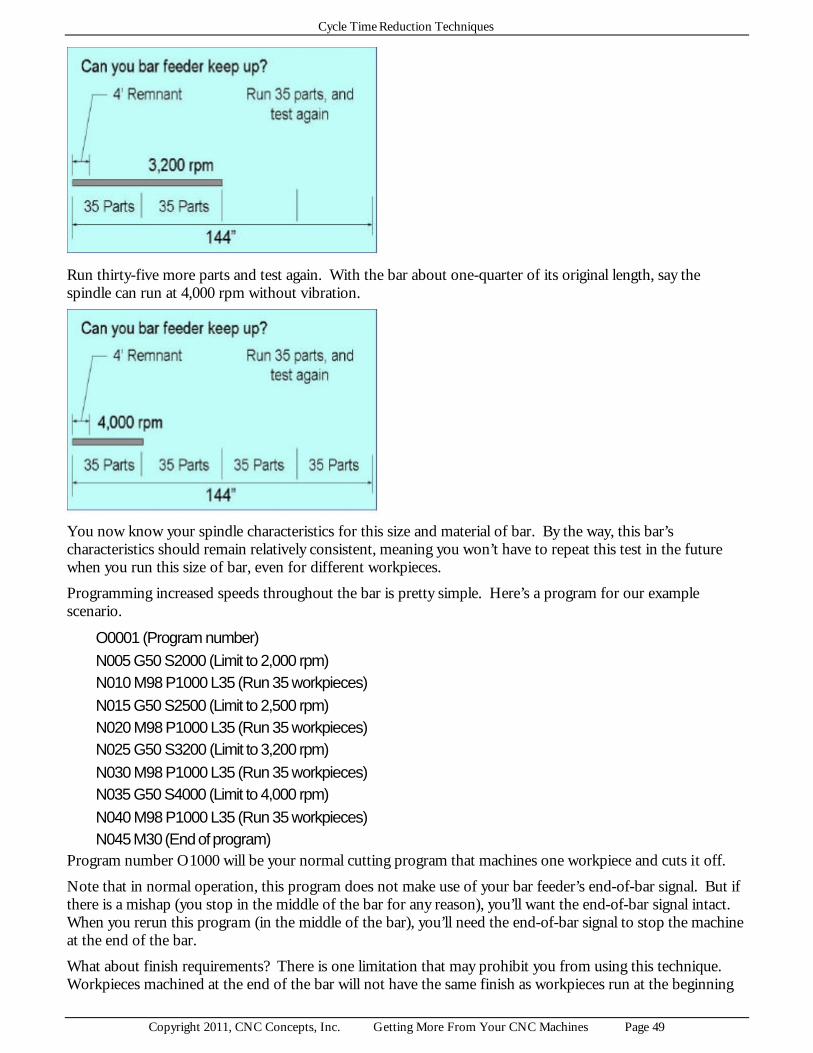
Cycle Time Reduction Techniques
Copyright 2011, CNC Concepts, Inc. Getting More From Your CNC Machines Page 49
Run thirty-five more parts and test again. With the bar about one-quarter of its original length, say the spindle can run at 4,000 rpm without vibration.
You now know your spindle characteristics for this size and material of bar. By the way, this bar’s characteristics should remain relatively consistent, meaning you won’t have to repeat this test in the future when you run this size of bar, even for different workpieces.
Programming increased speeds throughout the bar is pretty simple. Here’s a program for our example scenario.
O0001 (Program number) N005 G50 S2000 (Limit to 2,000 rpm) N010 M98 P1000 L35 (Run 35 workpieces) N015 G50 S2500 (Limit to 2,500 rpm) N020 M98 P1000 L35 (Run 35 workpieces) N025 G50 S3200 (Limit to 3,200 rpm) N030 M98 P1000 L35 (Run 35 workpieces) N035 G50 S4000 (Limit to 4,000 rpm) N040 M98 P1000 L35 (Run 35 workpieces) N045 M30 (End of program)
Program number O1000 will be your normal cutting program that machines one workpiece and cuts it off.
Note that in normal operation, this program does not make use of your bar feeder’s end-of-bar signal. But if there is a mishap (you stop in the middle of the bar for any reason), you’ll want the end-of-bar signal intact. When you rerun this program (in the middle of the bar), you’ll need the end-of-bar signal to stop the machine at the end of the bar.
What about finish requirements? There is one limitation that may prohibit you from using this technique. Workpieces machined at the end of the bar will not have the same finish as workpieces run at the beginning

Cycle Time Reduction Techniques
Copyright 2011, CNC Concepts, Inc. Getting More From Your CNC Machines Page 50
of the bar. Actually, workpieces machined at the end of the bar will have a better finish, since they have been run with appropriate cutting conditions. But if finish consistency is the primary concern (as it may be to your quality control people), this time-saving technique may not be appropriate.
Workpiece unload Much of what is required to unload workpieces is discussed during our discussions related to workpiece loading. Since the finished workpiece/s must be removed from the workholding device before the next one/s can be loaded, most CNC users consider the two tasks together. Frankly speaking, most points made about workpiece loading apply to workpiece unloading.
Here are the typical tasks related to workpiece unloading:
? Cycle completion light comes on (or automatic doors open) ? Unclamp workpiece from workholding device ? Remove finished workpiece ? Clean workholding device for next workpiece ? Place finished workpiece in storage container
Note that we are assuming that the operator is not cleaning, deburring or inspecting the finished workpiece in this discussion. We’ll address these tasks in the next topic. Here, we’re just considering those tasks an operator must do to get the finished workpiece out of the machine.
The priorities are, as always, to eliminate tasks, move them off line, or facilitate them.
Eliminate workpiece unloading tasks It’s likely that you cannot eliminate the entire workpiece unloading procedure. Finished workpieces must, of course be removed from the machine. But as you watch your CNC operators, what do you see that might be eliminate?
Possibly the task of cleaning the workholding device may be eliminated, for example, if its design minimizes or eliminates the possibility for chips to clog location surfaces. The design of horizontal machining centers helps eliminate this task, because chips naturally fall away from the workholding device during machining. An air blowing system may also be helpful if it can be activated from within the CNC program (cleaning the workholding device prior to the program’s completion).
Move workpiece unloading off line If you cannot find ways to eliminate the task, what can you do to move workpiece unloading tasks off line? The points made about pallet changers for machining centers related to workpiece loading also apply to workpiece unloading. With a pallet changer, and with a long enough CNC cycle, all workpiece loading will be done off line.
As stated during workpiece loading, be sure that the next workpiece gets loaded and run as quickly as possible. Operators should not be cleaning, deburring, and/or expecting the finished workpiece (unless they notice a severe problem) while the machine is down. Instead, these tasks (which are not actually part of workpiece unloading must be done while the machine is in cycle.
If finished workpieces require elaborate packaging, the task of packaging should also be done while the machine is in cycle.
Facilitate workpiece unloading tasks If workpiece unloading tasks cannot be eliminated or moved off line, what can you do to facilitate them? Automatic doors minimize fatigue and will open quicker than operators can manually open them. Cranes and other lifting devices can minimize fatigue and assist operators with the task of removing heavier workpieces. And again, the quality of the operator’s work area has lot to do with how quickly and easily they can perform off line workpiece unloading tasks (like packaging).

Cycle Time Reduction Techniques
Copyright 2011, CNC Concepts, Inc. Getting More From Your CNC Machines Page 51
As we keep saying, you must watch your own operators to come up with ways to minimize the workpiece unloading process.
Off line tasks done during every cycle What companies expect their CNC operators to do during the program’s execution will vary from one company to another. You must, of course, study your own list of related tasks. Here are some common tasks expected of CNC operators during every CNC cycle.
? Clean finished workpiece ? Debur finished workpiece ? Secondary operations on finished workpiece ? Perform tasks unrelated to CNC cycle ? Run two or more machines ? Inspect finished workpiece (workpiece attributes requiring 100% inspection) ? Report measured dimensions to statistical process control system ? What else might you expect your operators to do during the CNC cycle?
Where is the constraint? During our discussion of cycle time reduction principles, we ask you to make some comparisons to determine what part of a production run you should work on first. We’ve said that whatever makes up the greatest percentage of throughput time should be targeted first for improvement. While this works nicely to help you spot the biggest potential improvements in cycle time reduction, there is another way of setting priorities that we wish to expose you to.
One popular method for setting improvement priorities is to find the constraint that keeps you from completing a task - and eliminate it as the constraint. By eliminating a constraint, we mean find some way to lower the time/effort required to complete the task. Once you eliminate one task as the constraint, some other task will become the constraint (but you’ll be more efficient once the first constraint is eliminated). Find the current constraint, and eliminate it as the constraint. Once you do, yet another task will become the constraint. Continuous improvement involves constantly finding the current constraint and eliminating it.
When viewed on a company wide basis, you’ll be looking for the constraint that limits how quickly you can ship your product. Possibly you have three departments in the company, a mill department, lathe department, and grinding department. At the current time, possibly grinding department is the constraint, meaning your grinders cannot keep up with your mills and lathes. Grinding department must be eliminated as the constraint. Some way must be found to speed up the output of grinding department. Possible solutions include buying more equipment, working more shifts, improving grinding processes, or any combination of these solutions.
Once grinding department is no longer the constraint, some other department (possibly mill department) becomes the constraint. To improve further, a way must be found to eliminate it as the constraint. When this is done, possibly the constraint will become the lathe department - or possibly the grinding department will become the constraint again. Eliminate it as the constraint. This never-ending process is continued until everyone is satisfied with your company’s output.
Throughout our discussion of cycle time reduction thus far, we’ve been assuming that the CNC machine tool itself is your current constraint. And we’ve been looking for ways to improve the output of your CNC machine tools by reducing throughput time for each individual CNC machine. In essence, we’ve been treating each machine in your company as if it were the only machine your company owns, and we haven’t been considering any other possible improvement goals.
As we start looking at some of the other tasks you expect your operators to do in every cycle during a production run, you’ll notice that the CNC may not always be the constraint. Whether this is a good thing or a bad thing depends upon your point of view - and your improvement objectives.

Cycle Time Reduction Techniques
Copyright 2011, CNC Concepts, Inc. Getting More From Your CNC Machines Page 52
We’ve stated time and time again that any tasks you expect your operators to perform during every cycle (cleaning workpieces, deburring workpieces, secondary operations on workpieces, inspecting workpieces, packaging, etc.) must be done to reduce throughput time - not simply to keep the operator busy. And as long as the CNC machine is the constraint, we stand by this statement. Anything you do to reduce throughput time will help eliminate the CNC machine as the constraint.
But when looking at the bigger picture, having operators perform certain tasks while the machine is in cycle, even if they cannot keep up, may not be all that undesirable. If the CNC machine is not the company’s current constraint (overall, this CNC machine is producing what the company needs), finding ways to help the operator keep up with this machine will not improve the company’s output. In fact, improving this machine’s output in any way will not affect the company’s output! (So why are you working on this machine in the first place? - Find the constraint!)
Do keep in mind that if you have embarked on a continuous improvement program, eventually this machine will become the constraint. And when it does, helping the operator keep up will become of paramount importance.
What is the constraint of the CNC operation? As we present common tasks that companies expect their CNC operators to perform during each CNC cycle, we’ll continue to assume that it is important that operators keep up with your CNC machine tools. If operators can keep up, the CNC machine will be the constraint (take the longest time) in the CNC operation.
If operators are manually loading one workpiece per cycle, this means the operator must be able to keep up with program execution time needed to machine but one workpiece. If operators are manually loading multiple workpieces per cycle (machining centers only), they must be able to keep up with program execution time for the number of workpieces being machined. If workpiece loading is manually done off line (pallet changers on machining centers), operators must be able to load workpieces - and do any other expected task during the program’s execution. If machines are automatically loaded (or if using bar feeders), the operator must be able to keep up with the machine’s up-time for the number of workpieces the machine can produce without operator intervention.
If for any reason, an operator cannot keep up, the CNC machine itself will not be the constraint. Instead, whatever tasks you have the operator performing become the constraint. One of our most important concepts has been that CNC machines remain the constraint. We’ve been concerned that tasks that keep the operator from keeping up with the CNC machine, while important, are not as valuable as CNC machine time.
Admittedly, you may be willing to have operators that cannot keep up with CNC machines to gain the benefit of minimizing personnel. You may have no one else available to perform the task - or you may not be able to find and hire the number of people required to adequately staff your CNC environment. Indeed, this is one of the most common reasons why companies elect to have one person running two or more CNC machines, even though they cannot keep up.
We continue to stress that from a bottom line standpoint, however, you should be more willing to have a CNC person waiting on a CNC machine than a CNC machine waiting on a CNC person. As you consider how much you expect your operators to do during CNC cycles, remember that your CNC machine tools likely have the highest shop rates of any machines your company owns. If CNC machines will be waiting for CNC operators, be sure the tasks your operators perform are worth the lost machine time!
Operations on the completed workpiece Once a workpiece is removed from a CNC machine tool, operators are commonly expected to perform some additional operations on it. These operations almost always include cleaning and ensuring that the workpiece is dry (especially if there is any potential for corrosion) prior to placing it into its storage container.
Deburring is another operation that operators are commonly expected to perform on workpieces removed from CNC machines. No one wants to handle workpieces having sharp edges, and the person running the machine that caused the sharp edges is commonly responsible for removing them.

Cycle Time Reduction Techniques
Copyright 2011, CNC Concepts, Inc. Getting More From Your CNC Machines Page 53
Why are you doing this? Some companies even expect operators to perform other machining operations, like secondary operations, on workpieces removed from the CNC machine. This can be done for two purposes.
First, and most closely related to cycle time reduction, the CNC cycle may be so long that the operator has a great deal of time during the cycle (this is commonly the case with horizontal machining center cycles). To balance out the machine’s time with the operator’s free time, some of the machining operations previously done by the CNC machine will be eliminated from the CNC cycle and done by the CNC operator on another, less expensive, machine during the CNC cycle.
The operations are usually kept pretty simple to minimize the additional setup time required for the machine performing the secondary operation/s. One common example is tapping. Holes will be drilled on the CNC machining center, but tapping will be done by the CNC operator on a standard drill press using a tapping head. The primary concern when performing secondary operations must be that the CNC operator is able to keep up with CNC machine tool. If they cannot, and especially if they take longer than the CNC machine tool would to perform the same operation, expensive CNC machine time will be lost.
Second, some companies have their CNC operators performing operations on workpieces that the CNC machine is incapable of performing. During a turning center’s cycle, for example, the operator may use a conventional milling machine to mill a slot. Or they my use a drill press to drill some cross holes. (Remember that mill/turn machines are now available that allow turning centers to perform operations commonly done on a machining center.) Or maybe the CNC operator will perform a broaching, honing, grinding, or other operation that no CNC machining center or turning center can perform.
What about manufacturing cells? This second reason for performing machining operations on workpieces removed from CNC machines borders on what is commonly done in manufacturing cells. The primary goal with a manufacturing cell is to complete an entire workpiece, regardless of the range of machining operations that must be performed, in as short a period as possible. A secondary goal may be to do so with as few people as possible.
You can think of any manufacturing cell as being like a streamlined, single purpose company within a company. Any number of machines could be in the cell, including CNC and conventional machines. Indeed, some of the machines may not even be related to metal cutting. In similar fashion, any number of people could be working in the cell (though most companies try to minimize the number of people required).
Our discussion of constraints will apply nicely to any manufacturing cell. How long it takes to complete a workpiece in the cell is the cell’s throughput time. Assuming that all machines in the cell are automatic and running at the same time (which is seldom the case), this throughput time will be close to the run time for the machine having the longest run time. As with cycle time reduction for an individual CNC machine, the difference between throughput time and the longest cycle in the cell will probably be related to manual intervention. The operator/s can’t keep all machines running one hundred percent of the time.
The constraint for the cell will be the machine having the longest cycle, which may not even be a CNC machine. Whenever trying to improve the output for the cell, the cell’s constraint will be the primary focus.
Eliminate, move off line, facilitate Frankly speaking, everything we’ve been presenting about cycle time reduction for a given CNC machine tool will apply nicely to machining operations that occur during the CNC cycle. Just remember to start by determining the constraint.
If an operator is able to easily keep up with the CNC machine, the constraint is the CNC machine, not the internal operations. While improving the operator’s ability to perform secondary operations may make life easier for the operator, it will reduce throughput time.
On the other hand, if the operator cannot keep up, the constraint is the operator. In this case, anything you can do to reduce the time it takes the operator to complete the machining operations will reduce throughput time.

Cycle Time Reduction Techniques
Copyright 2011, CNC Concepts, Inc. Getting More From Your CNC Machines Page 54
And by the way, when you eliminate one constraint, you’ll always find another. If the CNC machine is the current constraint and you find a way to reduce program execution time, the CNC machine may no longer be the constraint. The performing of secondary machining operations by the operator will become the constraint. When you find a way to help them reduce the time it takes to complete the machining operations, the CNC machine will become the constraint again. Again, this leap-frogging of constraints can be a never-ending battle - one that occurs until everyone is satisfied with the output from the machine/operator combination..
Whether you’re working on an individual CNC machine with some secondary machining done by the operator, a manufacturing cell, or an entire company, your approach to cycle time reduction will be the same. First, find the constraint. Once you do, find ways to eliminate tasks. If you can’t justify eliminating tasks, find ways to move them off line. If you’re talking about secondary operations that are already “off line” relative to the CNC machine, moving tasks off line may be restricted to finding ways to double up on tasks done during the secondary operation/s. If you can’t find tasks to move off line, or you can’t justify doing so, your last alternative will be to facilitate tasks your operators must perform. And again, many of the topics already described, especially those related to preparation and organization, will apply nicely to machining operations an operator must perform during the CNC cycle.
Workpiece inspections done during the CNC cycle Many companies require that certain workpiece attributes be measured for every workpiece. Indeed, a company’s quality control department may demand 100% inspection. Additionally, most companies also expect some form of reporting to be done, once measurements are taken. A CNC operator may simply write measured dimensions down on a piece of paper (filling out a form) or they report measurement findings using a computer to the company’s statistical process control (SPC) system.
If your CNC operators are performing these inspections during the CNC cycle, again our major concern has to do with whether or not they can keep up with the CNC machine. If they can, measurement and SPC reporting is not the constraint (at least not currently), so we’d recommend that you work on reducing the other areas of running production in order to reduce throughput time. If measuring and reporting is the constraint, you must find ways to reduce the time it takes to perform the related tasks. (Eliminate, move off line, facilitate).
There are countless types of gauges used to measure workpiece attributes. They vary in ease-of-use, as well as in the skill level required to take measurements. Variable gauges (like micrometers, calipers, height gauges, etc.) are more difficult to use than fixed gauges (snap gages, go/no go gauges, bore gauges, etc.). Digital gauges are easier to read than gauges with Vernier scales or dials). Automatic gauges can automatically report the gauge’s current reading (the measurement just taken) while manual gauges require the error-prone tasks of interpreting and writing or typing the measured dimension.
The list of considerations required for wise decision is almost endless. We leave it to you to find ways to minimize tasks related to measuring workpiece attributes and reporting measurements taken. Again, eliminate, move off line, and/or facilitate.
Sizing (offset) adjustments due to tool wear With this presentation, we begin discussing tasks that are not done in every cycle, but do (or may) add to the length of time it takes to complete a production run.
The difference between initial adjustment, sizing adjustments, and tool replacement These are three somewhat similar, yet distinctly different tasks. By our definitions, the initial adjustment for a tool is done by the setup person during the running of the first workpiece. Once the workpiece passes inspection and the job goes into production, tool wear may cause sizing problems that must be corrected (more on sizing in just a bit). Since it is a production running task, it is done by the CNC operator. Tool replacement is the act of replacing dull tools and getting them to cut properly again. And again, it is the CNC operator that performs this task.

Cycle Time Reduction Techniques
Copyright 2011, CNC Concepts, Inc. Getting More From Your CNC Machines Page 55
We’re assuming in these presentations that all tools have been initially adjusted by the setup person prior to the CNC operator getting involved. We’ll be concentrating on sizing adjustments and tool replacement. Do note that many of the techniques used by the setup person to initially adjust each tool must be repeated by the CNC operator, especially during tool replacement..
More on sizing All cutting tools will eventually wear out and need to be replaced (tool replacement is the topic for our next discussion). During a tool’s life, small changes is sharpness and position will occur. These changes can affect the size, finish, and general quality of the surfaces they machine.
Different tool types have different effects on the workpiece as they dull. Some tools, like drills, will machine for their entire lives without a noticeable difference in the workpiece attributes they machine. With other tools, like reamers, there is really nothing that can be done about the wear condition of the tool (other than replacing it) when size or finish deviations occur. With yet other tools, like single point tools used on turning centers and boring bars used on machining centers, even a small amount of wear will immediately show up in workpiece size, and adjustments can be made that will keep the tool cutting properly until the tool completely dulls. These presentations will address tools that must be adjusted to deal with tool wear.
How important tool wear problems are to CNC users is partially dependent upon lot size. With a small lot (maybe under ten workpieces), the entire production run may be completed before any tools show noticeable signs of wear. As lot sizes grow, adjustments must be made, possibly several times, for the tools machining the most critical dimensions. For the purpose of this presentation, we’re assuming that your application requires operators to make sizing adjustments on a regular basis.
Here are the typical tasks related to sizing adjustments:
? Measure workpiece attribute ? Compare measured dimension to tolerance band ? If measured dimension is within required range, do nothing ? If measured dimension is coming close to tolerance limit, make adjustment: ? Determine target dimension ? Calculate deviation from measured dimension to target dimension ? If adjusting by offset, determine polarity of adjustment (+ or -) ? If adjusting by offset, make offset adjustment ? If adjusting by mechanical settings, adjust mechanical device
While experienced CNC people take the skills required to make sizing adjustments for granted, novices constantly struggle to learn what’s required. While simple arithmetic is all that’s required to make sizing adjustments, this tends to be one of the most error prone tasks an entry-level operator performs.
Wasted time, confused operators, scrapped workpieces, and even damaged machines are all symptoms of operators lacking the skills required to make sizing adjustments. If you’re currently experiencing any of these symptoms, it should be taken as a signal that you must find ways to improve this important task. Frankly speaking, you have two choices. First, you can improve the skill levels of your CNC operators (more and better training). Second, you can lower the skill level required to perform this task. More on how during our discussions for facilitating this task.
Most CNC users expect all sizing tasks to be done manually by their CNC operators. And again these tasks require skill. Required skills include measurement skills, math skills, evaluation skills, and offset entry skills. And of course, this means a great deal of manual intervention and potential for mistakes. To reduce some of the manual intervention and minimize potential for mistakes, some companies use measuring devices that automatically feed back to CNC machines for the purpose of sizing adjustments. But note that with most of these systems, only a few of the most critical dimensions are measured and controlled automatically. For many other (maybe less critical) dimensions, the operator must still make manual adjustments. I’ve been in

Cycle Time Reduction Techniques
Copyright 2011, CNC Concepts, Inc. Getting More From Your CNC Machines Page 56
more than one company that uses automatic feed-back gauges where management people don’t understand why CNC operators are having so many problems holding size. They think that all dimensions are automatically controlled, when in reality, their CNC operators control the majority of dimensions.
We begin by assuming that your operators are making (at least some) sizing adjustments manually. Much later, we’ll address automatic systems.
The entire task of sizing should be off line! All current model CNC machine tools allow offsets to be changed during the CNC cycle. This means operators can be making sizing adjustments while the machine is in cycle. The exception to this statement is a sizing adjustment that requires a mechanical adjustment on the cutting tool, as would be the case when adjusting the size of a boring bar’s diameter in a machining center job.
Though CNC machines allow offset adjustments to be done while the machine is in cycle, I still see many operators making offset adjustments during the workpiece loading process while the machine is down. They remove the previous workpiece, clean & debur it, and measure it. If an offset adjustment is required, they make the adjustment. Then they load the next workpiece and activate the cycle. In this case, workpiece sizing (as well as workpiece measurement) is an on-line task, adding to the length of time it takes to complete a production run.
While on-line offset adjustment may be necessary during the running of the very first workpiece (the setup person will want to confirm that one tool cuts correctly before going on to the next), you must ensure that sizing adjustments required during a production run are done off line.
Unless there is some kind of catastrophic failure (tool breakage), tool wear occurs gradually. After its initial adjustment during setup, for example, a finish turning tool will continue to machine the workpiece attributes within their tolerance bands. With the passing of time, and as the tool shows signs of wear, the diameters machined by this turning tool will begin to grow. But this growth occurs gradually. Quality control people don’t want your operators making offset adjustments on every workpiece. Instead, they want operators to allow dimensions to grow (or shrink for internal diameters) through most of their tolerance bands. As the most critical dimension (the one with the closest tolerance band) machined by a tool starts getting close to its limit, that’s when the operator will make the adjustment. And they can do so as the machine is in cycle.
If they happen to make the offset adjustment prior to the related cutting tool being invoked in the program, the adjustment will show up on the current workpiece. If the tool has already been invoked, the adjustment will show up on the next workpiece (but the current workpiece will still be within its tolerance band).
What offsets are you using for sizing? For turning centers, Fanuc calls the offsets used for sizing “wear offsets”. With machining centers, most controls require that you make sizing adjustments in either tool length compensation or cutter radius compensation offsets (though some machining centers also have a special set of wear offsets).
Wear offsets are usually easier to deal with, because they contain very small values. Geometry offsets for turning centers, as well as tool length compensation and cutter radius compensation offsets on machining centers are more difficult to work with because they contain large values that are unrelated to tool wear.
If an operator makes a mistake (possibly missing a decimal point) while adjusting a wear offset, it’s likely that they’ll catch it. A very large value may appear when the offset value should be quite small. On the other hand, they’ll be less likely to catch mistakes when the offset register being modified already contains large values.
Turning center users! Are you using offsets appropriately? Many of the sizing problems I see are related to the fact that companies don’t always appropriately use offsets in the first place. Consider this turning center scenario (a very common scenario).
During setup, the setup person measures the program zero point (commonly called touching-off tools) for all tools and enters the program zero assignment values into geometry offsets. As a geometry offset is entered,

Cycle Time Reduction Techniques
Copyright 2011, CNC Concepts, Inc. Getting More From Your CNC Machines Page 57
the corresponding wear offset for the tool is automatically cleared (set to zero). Say the second tool in the process is a finish turning tool. After it machines, the setup person finds that this tool has machined a diameter 0.003 inch too big. This is a critical tolerance, so an adjustment must be made. The setup person reduces the wear offset for this tool by 0.003 inch, and eventually turns the job over to an operator to begin the production run. Note that the offset for this tool begins at -0.003 inch.
As the production run continues, this tool begins to show signs of wear. The diameter it is machining has grown, and is getting close to the high limit of its tolerance band. Say the operator determines that an offset adjustment of -0.0008 inch is required to bring the diameter back to its target dimension. (After adjustment, the current value in the wear offset for this tool is -0.0038)
The operator continues with the production run. After several more workpieces this finish turning tool shows more signs of wear. The diameter it machines is again, 0.0008 inch larger that the target dimension and is getting close to its high limit. Again the operator makes the appropriate offset adjustment (current value in the wear offset for this tool is now -0.0046).
This process is repeated until the tool is completely dull and must be replaced. At this point, the CNC operator must replace or index the insert for the cutting tool. But if they do nothing to the tool’s wear offset, the next workpiece will likely be scrapped, because the new insert will machine more material from the workpiece than the old, worn insert did. In order to make the next workpiece a good one, the operator must set the wear offset for this tool back to its original value (-0.003 in our case). If the surfaces being machine by this tool are extremely critical, they may even have to trial machine. Either way, they’ll have to know the tool’s original wear offset setting as they replace the old tool.
Our point is that it may be wiser to make the initial offset adjustment in the tool’s geometry offset, not the wear offset (the setup person can make this initial adjustment in either register with identical results). This will allow the wear offset to start at zero. When the insert is replaced or indexed, the operator will know to reset its value to zero. If all initial adjustments are made in geometry offsets, all wear offsets can start the production run at zero. This will make it very easy for the operator during eventual tool replacement.
Admittedly, some setup people will complain about this technique, because if they make a mistake when entering the initial adjustment, they may not notice it (again, they will be modifying a very large value). Here is a custom macro B program that will allow setup people to make initial adjustments in wear offsets. Once the setup is completed and just before turning the job over to an operator, the setup person will run this program once. This program will transfer all wear offset values into geometry offsets, meaning all geometry offsets will be perfect and all wear offsets will be zero. It assumes you have a twelve station turret and at least 32 sets of offsets.
O8000 (Transfer wear offsets to geometry offsets) #100 = 1 (Start counter at one) N1 IF [#100 GT 12] GOTO 99 (If counter > number of turret stations, exit) #[2400 + #100] = #[2400 + #100] + #[2000 + #100] (Set geometry offset X equal to itself plus wear offset
X) #[2500 + #100] = #[2500 + #100] + #[2100 + #100] (Set geometry offset Z equal to itself plus wear offset
Z) #[2000 + #100] = 0 (Set wear offset X to zero) #[2100 + #100] = 0 (Set wear offset Z to zero) #100 = #100 + 1 (Step counter) GOTO 1 (Go back to test) N99 M30 (End program)
Our major point is that you make sure operators remember the starting point for each wear offset as they begin cutting with a new insert. If the starting point is zero, operators can easily remember.

Cycle Time Reduction Techniques
Copyright 2011, CNC Concepts, Inc. Getting More From Your CNC Machines Page 58
This may be more related to tool replacement (the topic of our next discussion) than sizing adjustments. But again, operators must know initial settings for wear offsets as they make sizing adjustments.
Eliminate workpiece sizing? Since all tools wear, this may not be possible. You may be able to prolong the period before sizing adjustments must be made (by using better cutting tools), but you will not be able to eliminate the task entirely.
What are you shooting for? However, you may be able to eliminate some of what the operator does during sizing adjustments. Calculating the target dimension is one such task.
If left to their own devices, you’ll probably find that different operators will be targeting different values within tolerance bands to hold. Most will target the mean value of the tolerance band. Some may target the high or low limit, depending upon which allows the longest period of time before an adjustment must be made. This problem is most severe when you have two or more operators working on the same job (first shift and second shift operators, for example). Everyone involved with the job may be targeting a different value!
Calculating the target dimension alone can be a cumbersome, time consuming task, even if operators are targeting the mean dimension of each tolerance band. For example, what is the mean value of this dimension and tolerance band?
? 3.0023 plus 0.0032 minus 0.0014 Most (even experienced) operators will need a calculator to calculate the mean value (3.0032). Do you ever see operators using a calculator while they’re making offset adjustments? Once calculated, hopefully they write the target value on the print so they don’t have to repeat this calculation every time this dimension requires sizing.
Eliminate the task of determining target values by doing so before the production run ever begins (okay, this is really moving the task off line). Have the programmer or a quality control person determine target values for every dimension. Some companies use process drawings for this purpose (though I’ve seen companies that use process drawings, but still don’t document target values). By the way, this also eliminates discrepancies in what different operators are using for target dimensions.
What is the deviation? Once the target dimension is known, the operator must determine the deviation between the measured dimension and the target dimension. This involve simple subtraction. Subtract the target dimension from the measured dimension, or vise versa. While experienced operators can often make this calculation in their heads, novices commonly turn to their calculators.
What is the polarity of the deviation? With most adjustments, the polarity is easy to determine. Simply subtract the measured value from the target value. If the measured dimension is currently too big (larger than the target value), this will render a negative polarity. If the measured dimension is too small, this will render a positive polarity.
For most CNC machines offset entry adjustment polarity directly corresponds to this deviation polarity. However, you must understand that with some turning centers, the X axis is reversed (X plus is the direction that sends the tool to a smaller diameter). One common machine that has this polarity reversal for the X axis is a gang style turning center. Actually, a gang style turning center has tools that can cut on both sides of the spindle centerline, meaning offset adjustment polarity for some tools (on the plus side of the spindle center) will be as just described, but for others, offset polarity will be reversed. This can create nightmares for CNC operators. They’ll have to know which tool machined a surface before they can make the correct decision!
Make the offset entry

Cycle Time Reduction Techniques
Copyright 2011, CNC Concepts, Inc. Getting More From Your CNC Machines Page 59
Once the deviation and its polarity are known, most controls make it quite easy to enter the deviation. The operator will first call up the offset page and bring the cursor to the offset value to be changed. The deviation and its polarity are then typed and entered. The current value of the offset will be incrementally modified by the entered value.
Eliminate all calculations! While experienced CNC operators can perform these tasks with relative ease, entry level operators are prone to making many mistakes. If your control allows parametric programming, there is actually a way to dramatically simplify what is involved with size-holding offset entries. This technique eliminates calculations, letting operators simply input measured dimensions. The control automatically calculates the deviation and its polarity, and correctly adjusts the appropriate wear offset. It also tests operator entries to confirm that entries are within a specified range. It even allows you to program the target dimension!
This technique is especially good because it allows your experienced people to continue making offset adjustments in exactly the same fashion as they are currently, while providing a much easier method for your inexperienced people. We’re showing the program for turning centers but a similar program could be developed for machining centers.
To eliminate calculations prior to offset entry on turning centers Almost every offset entries your operators make require some kind of calculation to be made before the offset value can be entered. Say, for example, the target diameter for a turning tool is 3.2342 and its tolerance is plus or minus 0.002. After machining with the finish turning tool, the operator finds that the diameter being turned is 3.2351. Though the workpiece is still within its tolerance band, the operator will eventually want to adjust the offset to bring the workpiece on size. In order to do so, the operator must subtract the measured dimension from the target dimension (3.2342 - 3.2351 in this case) to come up with the amount of offset change (-0.0009 in our case). Though our example involves an easy subtraction, even simple calculations do take time, even for experienced operators and opens the door to making mistakes. Mistakes, of course, will result in scrapped workpieces. Offset adjustments of this nature, of course, are made countless times (especially on finishing tools) during a production run.
Note that your operators may have much more difficult calculations to make before an offset can be adjusted. If they measure dimensions over a ball, over pins, or by some other means that renders something other than the dimension specified on the print, it is likely that the required calculations will be much more difficult, maybe even requiring some trigonometry. Truly, any time you see your operators using a calculator before they enter an offset adjustment should be taken as a signal that you can do something to help them and minimize offset setting time!

Cycle Time Reduction Techniques
Copyright 2011, CNC Concepts, Inc. Getting More From Your CNC Machines Page 60
Custom macro B allows you to access your offsets from within the program. You can also make calculations to determine the value by which a n offset must be adjusted (the deviation). And of course, you can then actually change an offset value by the appropriate amount based upon the result of a calculation.
Given our previous example, the target diameter to be turned on a turning center is 3.2342 inch. Say that tool number five is the turning tool that machines this diameter. After machining the operator would normally adjust tool (wear) offset number five to input any discrepancy (by -0.0009 in our previous example). Instead of forcing the operator to calculate the deviation amount, wouldn’t it be easier for the operator to actually enter the current machined diameter (3.2351 in our case)?
How it works Our given technique will allow the operator to do just that, eliminating the calculation prior to offset entry. But instead of making this adjustment in offset number five, we’ll pick a secondary offset number into which they enter the measured size. Since most turrets can hold no more than twelve tools, we’ll simply add twenty to the tool station number to come up with the secondary offset number. For tool number five, we’ll tell the operator to enter the measured value into offset twenty-five.
The custom macro program will check to see if there is any value in the secondary offset (other than zero). If there is, the operator has just entered the actual size of the workpiece that is deviating from its target size. In this case the program will automatically make the calculation to determine the correct offset adjustment value (just as the operator is currently doing manually) and adjust the primary (wear) offset accordingly.
What is the target dimension? One problem that you must address has to do with the fact that a turning tool or boring bar can machine any number of different dimensions on a workpiece. If more than one diameter is being turned, for example, the operator must know which diameter is to be used as the offset adjustment diameter. Be consistent. You could pick the first diameter being machined by the tool or the most critical diameter (having the tightest tolerance).
Minimizing repeated calculations If you wish to use this technique for all tools which require frequent offset adjustments (commonly your finish turning tools & boring bars, threading tools, and grooving tools), you would have quite a few redundant commands in your main program to perform the secondary offset testing and calculations. For very high volume work, this may be just fine. But the more programs you need to run, the more inconvenient it would be to incorporate these redundant commands in your main program. To minimize the number required commands, our technique uses a separate program (the custom macro) for this purpose.
In the main program, place this command at the beginning of every tool (note that this command must come before the turret index command).
. N050 G65 P8002 T5. D3.2342 S3.22 B3.245 (Check to see if offset adjustment is necessary, if so, make
the adjustment) N055 T0505 (Finish turning tool) .
In line N050, we call the custom macro and specify the tool station number being used (with T) and the target value for the dimension that is being measured (with D). Note that our custom macro is even going to test the operator’s input data to confirm that it is within allowable limits (maybe they measured the wrong diameter or entered the value incorrectly). If it is not, an alarm will be sounded. S specifies the small limit and B specifies the big limit.
Here is the custom macro program.
O8002 (Custom macro to calculate and set offsets) IF [ #[2020 + #20] EQ 0 ] GOTO 99 (If operator has not entered a value, exit)

Cycle Time Reduction Techniques
Copyright 2011, CNC Concepts, Inc. Getting More From Your CNC Machines Page 61
IF [ #[2020 + #20] GT #19] GOTO 5 (If offset value is greater than small limit, go to N5) #3000 = 100 (DIMENSION OFFSET TOO SMALL) N5 IF [ #[2020 + #20] LT #2] GOTO 10 (If offset value is less than big limit, go to N10) #3000 = 101 (DIMENSION OFFSET TOO BIG) N10 #[2000 + #20] = #[2000 + #20] + [#7 - #[2020 + #20]] (Adjust primary offset) #[2020 + #20] = 0 (Set secondary offset back to zero) N99 M99
The first IF statement tests to see if the operator has entered a value in the secondary offset. They will only do this, of course, when the workpiece requires sizing adjustment. If no offset adjustment is necessary (the secondary offset value is zero), the control will simply exit this program. If this IF statement is false, the operator has entered a value into the secondary offset and the control will proceed to the next line.
The next two IF statements test for the limits of the value entered into the secondary offset. An appropriate alarm will be generated if it is not within the allowable limits. Note that these limits probably don’t correspond to the tolerance limits. Again, you’re simply trying to confirm that the operator has entered an acceptable value
As long as the entry is acceptable, line N10 makes the necessary offset adjustment based upon the same calculation the operator is currently making manually. Note that this example program adjusts the primary offset based upon simple addition and subtraction. If you have more elaborate calculations to make (measuring over a ball for example), of course you’ll have a different calculation to make.
After making the offset adjustment, the line with #[2020 + #20] = 0 sets the secondary offset back to zero so that the primary offset will not be adjusted again until the operator enters another value in the secondary offset (several parts from now).
A note about current methods Note that this technique simply builds upon your current methods. If setup people or operators wish to enter offsets using current methods (maybe your setup people or more experienced operators wish to do this), they can do so (this technique won’t interfere with your current methods). But your entry level operators will surely find this method of offset entry much easier, faster, and less error prone than your current methods.
To eliminate calculations prior to offset entry on machining centers While machining center sizing adjustments are not usually as critical as those made for turning centers (most tools may last for their entire lives without needing sizing adjustments), the same technique can be used to help operators keep from having to make sizing adjustments prior to offset entry.
In our simple example, we’re milling the right side of the workpiece. Tool station number six is the milling cutter, and offset number thirty-six is being used to specify the diameter of this cutter. This offset also, of course, is used to adjust the size machined by this milling cutter. If the 4.0121 dimension comes close to the high limit (the milling cutter is wearing), the operator normally adjusts offset number thirty-six.
As with the turning center example, we can keep the operator from having to determine the deviation’s amount and polarity. Instead, we can allow them to enter the actual size of the workpiece just measured. For our example, we’re choosing offset number sixty-six (sixty plus the tool station number) into which they will enter the workpiece current size when they want to make a sizing adjustment. All basic functions of this program remain exactly the same as presented for the turning example.
In the cutting program, and just before the tool change to the milling cutter, this command is given:
N050 G65 P8002 T6.0 D4.0121 S4.0111 B4.0131 N055 T06 M06
Again, T represents the tool station number. D is the target dimension. S is the small limit for operator entry. And B is the big limit for entry.

Cycle Time Reduction Techniques
Copyright 2011, CNC Concepts, Inc. Getting More From Your CNC Machines Page 62
Here is the parametric program (custom macro) that determines if the operator has made an entry, and if so, adjusts the cutter radius compensation offset, offset number thirty-six in our case.
O8002 (Custom macro to calculate and set offsets) IF [ #[2060 + #20] EQ 0 ] GOTO 99 (Operator made an entry?) IF [ #[2060 + #20] GT #19] GOTO 5 (Test against small limit) #3000 = 100 (DIMENSION OFFSET TOO SMALL) N5 IF [ #[2060 + #20] LT #2] GOTO 10 (Test against big limit) #3000 = 101 (DIMENSION OFFSET TOO BIG) N10 #[2030 + #20] = #[2030 + #20] + [#7 - #[2060 + #20]] (Adjust) #[2060 + #20] = 0 (Set entry offset back to zero) N99 M99 (End of custom macro)
Again, this program is very similar to the one related to eliminating calculations prior to offset entry on turning centers.
What about more complicated offset entries? Note that in each of our sizing example programs, the parametric programs are simply performing basic arithmetic calculations. It may be possible that your operators are currently having to perform more complex calculations prior to making offset adjustments. In the next drawing, for example, a measurement is being taken over a ball.
In this case, it is likely that some trigonometry must be done before the operator can determine how much to adjust an offset. Remember that sizing parametric program can help you eliminate calculations prior to offset entry regardless of how complex the calculation. Indeed, the more complex the calculation, the more this kind of program can help!
Use offsets for sizing adjustments whenever possible We’ve already said that workpiece sizing adjustments should be made while the machine is in cycle. And as long as sizing is done with an offset change, this is entirely possible. However, there are some special applications when programmers may be tempted to have operators make size-holding adjustments with program changes. One turning center example is when unwanted taper is showing up on a critical diameter. Possibly the workpiece is pushing away from the tool whenever the tool machines further away from the chuck. But as the tool gets closer to the chuck, the setup is more rigid and the workpiece does not push away.
Here is an example program that shows how operators can easily eliminate unwanted taper by changing one program command:
O0001 (Program number) .

Cycle Time Reduction Techniques
Copyright 2011, CNC Concepts, Inc. Getting More From Your CNC Machines Page 63
.
. N130 T0404 M42 (Finish turning tool, select high spindle range) N135 G00 G96 S500 X3.75 Z0.1 M03 (Rapid to approach position) N140 G01 Z0 F0.01 (Feed flush with face) N145 X4.0 Z0 (Machine chamfer on face) N150 Z-4.0 U0.0003 (Machine diameter prone to taper) N155 . . . . . .
Notice that in line N150, a four inch diameter is being machined. Yet because of tool pressure problems (again, more support at the chuck end), the workpiece is experiencing a taper in this diameter. If nothing is done, this diameter will currently have a 0.0003 taper, with the chuck end being smaller. The programmer has included a U word in this command (incremental X motion) to allow the operator to specify the amount of unwanted taper currently being machined in the diameter. Note that as the tool dulls, the tool pressure will change, meaning that it is likely that a taper-eliminating adjustment will have to be made several times during each tool’s life.
While this technique works nicely to eliminate the unwanted taper, note that most controls do not allow you to be modifying a program while the program is running. This means the machine must not be in cycle whenever an adjustment must be made (adjustments will be made on line). If an adjustment must be made several times during each tool’s life, this could add up to a great deal of wasted production time.
This problem can also be handled with offsets. One offset (the primary offset) will control the diameter at the front end and another will control the diameter of the chuck end. Here is a modified program that shows the two offset instating commands.
O0001 (Program number) . . . N130 T0404 M42 (Finish turning tool, select high spindle range) N135 G00 G96 S500 X3.75 Z0.1 M03 (Rapid to approach position) N140 G01 Z0 F0.01 (Feed flush with face) N145 X4.0 Z0 (Machine chamfer on face) N150 Z-4.0 T0424 (Machine diameter prone to taper) N155 . . . . . .
Notice that as the tool machines the four inch diameter in line N150, we switch to the secondary offset (we recommend adding twenty to your tool station number to come up with this secondary offset number). The amount of taper, 0.0003 in this case, will be reflected as an X axis offset difference between offsets four and twenty-four (offset number four’s X will be 0.0003 smaller than offset number twenty-four’s X value. Note that the Z values in each offset must be identical. While this technique may take some getting used to, with it you can ensure that all size-holding adjustments made for the diameter will be off line.

Cycle Time Reduction Techniques
Copyright 2011, CNC Concepts, Inc. Getting More From Your CNC Machines Page 64
What about mechanical size holding adjustments? Again, certain tools require physical adjustments on the tool itself to make them machine differently. A machining center boring bar, for instance, requires that the operator turn a dial on the boring bar to increase or decrease the diameter the boring bar will cut.
With this kind of tool, it’s likely that any sizing adjustments will be done on line. In fact, it is likely that the operator will actually measure the workpiece on line, as manual intervention during the CNC cycle right after the finish boring bar machines one of its holes.
One (rather expensive) way to eliminate the task of manually adjusting the boring bar involves a machine feature called the U axis. The U axis is a direction of motion that allows tool motion perpendicular to the spindle centerline. With the U axis, a CNC user can actually change the diameter that any cutting tool will machine. The most popular application for the U axis is to allow machining centers to perform turning-like operations. Contour machining a port within a hole is one such application.
The U axis also the operator to fine tune boring operations without mechanical adjustments. When machines are equipped with this feature, the operator will be making sizing adjustments with offsets, eliminating the tedious (on line) task of measuring and sizing. While this machine feature may be difficult to justify if you only finish bore occasionally, it may be relatively easy to justify if you finish bore on a regular basis. By the way, the U axis feature also allows you to bore holes having different diameters (within a range) with one tool.
If you cannot find ways to eliminate these tasks, maybe you can move some off line. More and more current model machining centers come with tool changing systems that let an operator safely rotate the tool changer magazine during the CNC cycle. With this kind of magazine, the operator may be able to perform the actual adjustment on the boring bar while it is in the magazine - when the machine is machining with another tool.
Admittedly, a great deal of finesse goes into mechanically adjusting a boring bar. And depending upon the boring bar style and the skill level of the operator, the operator may have to test cut to confirm that the adjustment just made is correct. If this is necessary, why not make it as easy as possible to perform this on-line task by providing trial boring and adjustment commands in the program? Using optional block skip (block delete), the operator will turn off the optional block skip switch whenever they want to perform the trial boring and sizing operation. Note that this will also be helpful during the boring bar’s initial setup and when replacing boring bar inserts during tool replacement. Here is an example program showing how it’s done.
.
.
. N075 T05 M06 (Place boring bar in spindle) N080 G54 G90 S500 M03 T06 (Select coord. system, abs mode, start spindle, get next tool ready) N085 G00 X2.0 Y1.5 (Move to hole center in XY) N090 G43 H05 Z0.1 (Instate tool length compensation) N095 M08 (Turn coolant on) N098 F2.0 (Sub-program must be universal, so feedrate is specified in main program) / N100 M98 P1000 (First try) / N105 M98 P1000 (Second try) / N110 M98 P1000 (Third try) / N115 M98 P1000 (Fourth try) N120 G86 R0.1 Z-1.25 F2.0 (Completely machine hole) N125 X5.0 (Machine second hole) N130 G80 (Cancel cycle) N135 . . .

Cycle Time Reduction Techniques
Copyright 2011, CNC Concepts, Inc. Getting More From Your CNC Machines Page 65
. Notice the slash codes in lines N100 through N115. If the operator turns off the optional block skip switch, the machine will execute program O1000 and perform the trial boring operation. Under normal conditions, the operator will leave the optional block skip switch on. Here is the sub-program.
O1000 (Subprogram for trial boring) N1 G91 G86 R0 Z-0.3 (Trial machine hole 0.2 in deep) N2 G80 (Cancel cycle) N3 Z2.0 (Rapid away in Z) N4 X3.0 Y3.0 (Move to convenient measuring position) N5 M00 (Stop for measurement) N6 G00 X-3.0 Y-3.0 (Move back to hole in XY) N7 Z-2.0 (Move back to 0.1 above hole) N8 G90 (Re-select absolute mode) N9 M99 (End of subprogram)
This sub-program is universal, meaning it will work for any hole of any diameter in any location (notice that it is written incrementally). After boring but 0.200 inch deep, the tool will move to a convenient measuring and adjustment position. The machine will then stop for the measurement in line N5. After measuring and adjusting, the operator will simply press the cycle start button. This sub-program ends by leaving the tool where it started. Back in the main program, the very next command is another slash-coded command telling the control to come back to this sub-program. So the trial boring pass is repeated. This time, it is likely that the hole is to size, so after measurement, the operator will turn on the optional block skip switch and the control will ignore the balance of trial machining passes in the main program (note that the operator is given four tries to get the adjustment made in our example program).
Any time you see an operator struggling to hold size with a tool, and especially if it’s done on line, you can probably find a way to facilitate the sizing operation by programming special trial machining commands to help them take measurements and make adjustments.
Facilitating workpiece sizing tasks Most of what has been presented to this point, while included in our discussion of eliminating tasks related to workpiece sizing, has been equally related to facilitating the error-prone task of workpiece sizing. Just about everything we’ve suggested will make life much easier for CNC operators. Here we simply continue discussing ways to simplify tasks.
What do your operators use to measure? The quality of your gauging devices has a lot to do with how difficult it will be to make sizing adjustments. Operators must first, of course, measure a workpiece attribute that is prone to variation due to tool wear. And of course, they must come up with an accurate measurement. Here are but a few points about gauging devices.
? Pre-set gauges provide actual deviation amount (no measurement required) ? Digital gauges display actual measured dimension ? Variable gauges are more difficult to use than fixed gauges
As you watch your operators take measurements, find ways to eliminate, move off line, and/or facilitate these tasks. The more mistakes operators make, and the more time it takes them, the more important this need.
How good is your production run documentation? Operators must, of course, know what dimensions are critical and most prone to varying due to tool wear. This being the case, I’m amazed how many companies provide no instructions to their CNC operators. They expect operators to figure out which dimensions are critical (based upon tolerances) as well as which tool
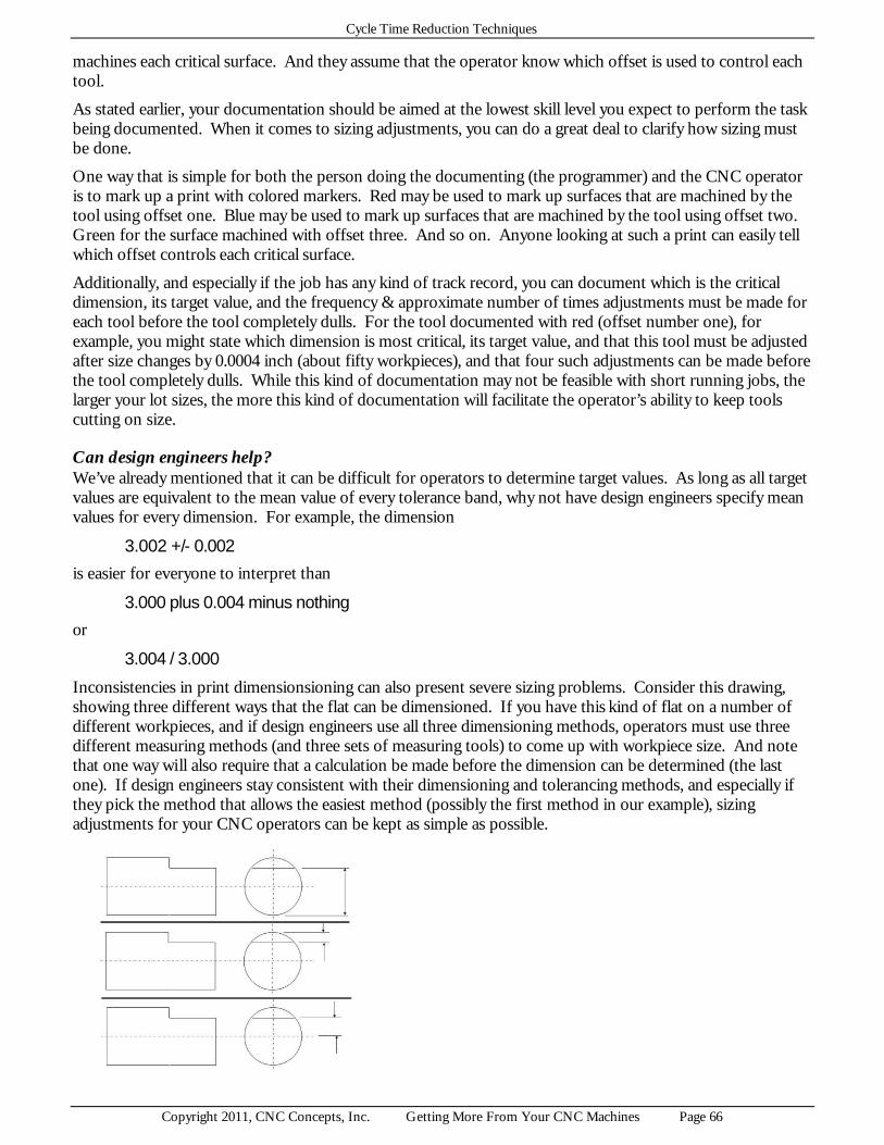
Cycle Time Reduction Techniques
Copyright 2011, CNC Concepts, Inc. Getting More From Your CNC Machines Page 66
machines each critical surface. And they assume that the operator know which offset is used to control each tool.
As stated earlier, your documentation should be aimed at the lowest skill level you expect to perform the task being documented. When it comes to sizing adjustments, you can do a great deal to clarify how sizing must be done.
One way that is simple for both the person doing the documenting (the programmer) and the CNC operator is to mark up a print with colored markers. Red may be used to mark up surfaces that are machined by the tool using offset one. Blue may be used to mark up surfaces that are machined by the tool using offset two. Green for the surface machined with offset three. And so on. Anyone looking at such a print can easily tell which offset controls each critical surface.
Additionally, and especially if the job has any kind of track record, you can document which is the critical dimension, its target value, and the frequency & approximate number of times adjustments must be made for each tool before the tool completely dulls. For the tool documented with red (offset number one), for example, you might state which dimension is most critical, its target value, and that this tool must be adjusted after size changes by 0.0004 inch (about fifty workpieces), and that four such adjustments can be made before the tool completely dulls. While this kind of documentation may not be feasible with short running jobs, the larger your lot sizes, the more this kind of documentation will facilitate the operator’s ability to keep tools cutting on size.
Can design engineers help? We’ve already mentioned that it can be difficult for operators to determine target values. As long as all target values are equivalent to the mean value of every tolerance band, why not have design engineers specify mean values for every dimension. For example, the dimension
3.002 +/- 0.002
is easier for everyone to interpret than
3.000 plus 0.004 minus nothing
or
3.004 / 3.000
Inconsistencies in print dimensionsioning can also present severe sizing problems. Consider this drawing, showing three different ways that the flat can be dimensioned. If you have this kind of flat on a number of different workpieces, and if design engineers use all three dimensioning methods, operators must use three different measuring methods (and three sets of measuring tools) to come up with workpiece size. And note that one way will also require that a calculation be made before the dimension can be determined (the last one). If design engineers stay consistent with their dimensioning and tolerancing methods, and especially if they pick the method that allows the easiest method (possibly the first method in our example), sizing adjustments for your CNC operators can be kept as simple as possible.

Cycle Time Reduction Techniques
Copyright 2011, CNC Concepts, Inc. Getting More From Your CNC Machines Page 67
Can programmers help? Knowing that an operator is struggling to hold size with a given tool, there are any number of things programmers can do to help. We’ve already mentioned the programming of trial machining for boring bars used on machining centers. You also know that with parametric programming, you can eliminate the calculations that must be done prior to offset entry. As you study a particular task that is causing problems for your operators, and if you use a little ingenuity, you’ll surely come up with other ways to help.
Automatic workpiece sizing systems Though these systems are expensive, and may be difficult to justify for general purpose work, there are automatic systems that will measure workpieces, report statistical process control findings, and feed back to the CNC machine with offset adjustments when required. Most come in the form of “post process” gauging systems, meaning they measure the workpiece after it is removed from the CNC machine tool. The operator (or automatic loading system) will remove the workpiece from the machine and place it into a special gauging fixture. Gauges within the fixture will measure the most critical dimensions, and if necessary, make offset adjustments to keep the machine cutting on size.
Another form of automatic gauging system is call “in-process” gauging. With this system, gauging is done during the CNC cycle. This, of course, means that measuring is done on line and will add to the length of time it takes to complete a production run. For this reason, we prefer post process gauging systems.
For machining center applications, the device used to perform measurements is commonly a spindle touch probe. The probe will usually require from 1-4 seconds per touch, and depending upon the number of touches required to complete a measurement, could have a dramatic impact on cycle time. This increase in cycle time may be acceptable if the workpiece cannot easily be moved from the machine for measuring, as would be the case with large, heavy workpieces.
Another limitation of using a spindle touch probe is related to accuracy. Most tooling engineers would agree that the device used for measuring should have a tolerance with ten percent of the tolerance it is used to measure. If, for instance, you’re measuring a dimension having a 0.001 inch overall tolerance, your measuring device should have a tolerance of 0.0001 inch or less.
It can be difficult to get a firm specification of spindle probe accuracy from machine tool builders and probe manufacturers. The probe manufacturer may claim their probe will trigger within 20 millionths of an inch of stylus deflection. But triggering is but the first step to probing a surface. Some of the best claims we’ve heard for overall probing system accuracy are in the neighborhood of plus or minus 0.0002 inch, meaning the closest tolerance you should be trying to measure will be plus or minus 0.002 inch or more. Be sure to get a firm guarantee of probing overall accuracy before you decide to use a spindle probe for in-process gauging.
Keep in mind that most in- or post-process gauging systems will only measure a small percentage of a workpiece’s dimensions. While these may be the most critical (and most difficult to manually measure), your CNC operators will probably have to perform many other sizing adjustments to hold size on workpiece attributes that are not measured by the automatic system.
Dull cutting tool replacement (tool maintenance) This task is directly related to your typical lot size. With very small lots, it’s likely that you’ll complete the entire production run before any of the cutting tools completely dull. On the other hand, if you typically run very large lots, your operators may have to eventually replace all of the tools used in the job. We’re assuming in this presentation that you have at least some tools that must be replaced during each production run.
Here are the typical tasks related to replacing worn tools:
For machining centers:
? Remove tool from machine ? Ensure tool is in tool changer magazine ? Rotate magazine to appropriate removal station

Cycle Time Reduction Techniques
Copyright 2011, CNC Concepts, Inc. Getting More From Your CNC Machines Page 68
? Remove tool ? Remove cutting component from the tool (insert/s or cutting tool) ? Replace cutting tool component ? If necessary, measure new offset values ? Cutter radius ? Tool length ? If necessary, enter new offset values ? Cutter radius ? Tool length ? Load new tool into machine ? Rotate magazine to appropriate station ? Load tool ? If necessary, trial machine to confirm workpiece size
For turning centers:
? Remove cutting component from the tool (insert or cutting tool) ? Rotate turret ? Remove cutting component from tool ? Replace cutting tool component ? If necessary, determine & enter new offset values ? Geometry offsets ? Tool nose radius compensation ? If necessary, trial machine to confirm workpiece size
When is tool replacement required? Most companies leave it completely to their CNC operators to determine when dull tools must be replaced. This leads to inconsistencies among operators. The day shift operator, for example, may feel that a tool is dull after but 100 workpieces, but the night shift operator gets close to 200 parts from same insert. If you don’t give any guidance to operators about insert replacement, you’re in for this kind of inconsistency.
Admittedly, it will be next to impossible to come up with firm tool life expectancies, and you must provide your operators with some leeway for insert replacement. But this doesn’t mean you can’t provide some help in this regard.
Probably the best way to provide help is with a tool life management system, and we’ll describe them in detail a little later. One benefit of a true tool life management system that you can simulate with parametric programming techniques is alerting the operator when tools must be replaced.
Again, tool life cannot be cut in stone, but if you know that all roughing inserts used in a job will wear out after about 200 workpieces, and that all finishing tools will wear out after about 350 workpieces, why not have the machine stop at the appropriate times, and tell the operator to replace worn tools?
By the way, grouping tools in this manner (roughing tools, finishing tools, etc.) may not be perfect. One roughing tool may last a little longer than another. But in many cases, the time gained by allowing a cutting tool to stay in use for as many workpieces as possible may be lost due to additional tool replacement time. An operator can surely replace several tools at one time faster than they can replace the same tools individually at different times. If the operator is expected to do other things during the cycle, this will minimize the number of times they must break away to perform tool replacement tasks.

Cycle Time Reduction Techniques
Copyright 2011, CNC Concepts, Inc. Getting More From Your CNC Machines Page 69
Here is an example main program that uses custom macro B program to alert operators to replace cutting tools.
O0001 (Cutting program) . . . . N350 G65 P8001 R200.0 F350.0 (Call custom macro and test if tools are dull) N355 M30
Just before the end of this main (cutting) program, line N350 calls a custom macro to have it test whether inserts must be changed. We use the letter address R to specify how may workpieces can be machined by the roughing tools and F to specify how many workpieces can be machined by the finishing tools before tool replacement must be done.
Here is the custom macro B program
O8001 (Program number) #500 = #500 + 1 (Step counter for roughing tools) IF [#500 LE #18] GOTO 50 (If roughing tools are okay, step counter and test finishers) #500 = 0 (Reset roughing tools counter to zero) #3000 = 100 (REPLACE ROUGHING TOOLS) N50 #501 = #501 + 1 (Step finishing tools counter) IF [#501 LE #9] GOTO 99 (If finishing tools are okay, step counter and exit) #501 = 0 (Reset finishing tools counter) #3000 = 101 (REPLACE FINISHING TOOLS) N99 M99 (End of custom macro)
This program uses two permanent common variables (#500 and #501) to keep track of the current part count). Whenever one of these values becomes larger than the number of workpieces that can be machined, an appropriate alarm will sound. While this program will nicely alert operators when they must change tools, this barely scratches the surface of what can be done with a true tool life management system.
Do you need to replace tools at the beginning of each shift? The answer to this question is usually “No!”. However, some operators can’t seem to kick the habit of replacing all inserts as soon as they begin their shift. Admittedly, operators may not know how long certain inserts have been cutting, especially if the machine has been sitting idle for a long period of time (an off-shift for example). It may seem simpler to them to just go ahead and replace all tools, regardless of whether any are dull.
Improved communication among operators may help. Or, if you use the kind of program described earlier to alert operators when tools are truly dull, they won’t arbitrarily change inserts at the beginning of every shift.
Eliminate these tasks? While you may be able to postpone dull tool replacement (by using the very best cutting tools and compromising cutting conditions), you will not be able to eliminate the task entirely. All cutting tools will eventually dull.
If your lot sizes commonly border on being small enough to allow operators to get through an entire production run without tools getting dull, you may be able to eliminate this task by finding better tools that will last longer or by slowing the cutting conditions. While slowing cutting conditions may cause a longer button-to-button time, throughput time may be reduced if operators never have to change inserts.

Cycle Time Reduction Techniques
Copyright 2011, CNC Concepts, Inc. Getting More From Your CNC Machines Page 70
If you cannot completely eliminate this task, look for ways to eliminate parts of it. Some machining centers, for example, allow your operator to safely manipulate the tool changer magazine while the machine is in cycle. This may allow your operators to replace worn inserts while they are in the tool changer magazine, eliminating the need to completely remove the tool.
You may be able to eliminate the need for trial machining with a replaced tool if you can perfectly determine the tools setting position. Consider, for example, purchasing inserts having smaller tolerances. If you purchase (more expensive) inserts with smaller tolerances, your operators may be able to replace inserts consistently enough that trial machining is not required. We’ll discuss insert tolerances a little later.
Move tool maintenance tasks off line Since you will not be able to completely eliminate tool maintenance, your goal should be to move all tool maintenance off line. That is, don’t let tool maintenance add to the length of time it takes to complete a production run. How close you can come to achieving this goal depends upon several factors.
Can you be removing and replacing tools while the machine is in cycle? Consider CNC turning centers. Can you think of any way that your operator can be replacing tools in the machine’s turret while the machine is running a workpiece? Probably not. But do remember that some turning centers are available with a tool changing mechanism that resembles those used on CNC machining centers. With this devices, a tool can be quickly loaded into the machine’s turret.
The operator can be loading fresh tools into the turning center’s automatic tool changer magazine while the machine is running production. When, required, these tools can be quickly placed into the machine’s turret, keeping most of the tool replacement time off line.
More and more machining centers do allow the operator to safely replace tools in the machine’s automatic tool changer magazine while the machine is in cycle. At the tool changer magazine, the operator can place the magazine in the “manual” mode (a simple two-position switch is commonly used for this purpose). When placed in the manual mode, the machine will automatically remember the tool that is currently in the waiting or ready station, so when the magazine is eventually placed back in “automatic” mode, the magazine will rotate back to this station. If a tool change is commanded while the magazine is in manual mode, the machine will simply wait until the operator places the switch back in automatic mode to make the tool change.
This means the operator will be able to safely replace tools, even when the machine is in cycle. They’ll just have to wait for a tool that cuts for a long enough length of time.
Can you justify duplicating tools? In order to move all tool maintenance off line, someone must be setting up a duplicate tool while the machine is running production.
Do you have a tool life management system? Tool life management systems will complete your ability to move all tool maintenance tasks off line. Here are some of their more important attributes.
Commanding tools by a group - Instead of commanding individual tool stations, you’ll be commanding tool groups. The current or active tool in the group will be the one that is actually placed into the cutting position (spindle of a machining center of turret index position of a turning center). For those tools that are most prone to failure, you’ll have more tools in the group.
A tool life specification - All tool life management systems allow you to specify a tool’s life period. The best ones allow you to specify the period in time, as well as in number of workpieces (time is usually better because it will lend itself better to multiple production runs).
Dull tool alert - Most machines use a blinking yellow light to alert the operator, telling them that one or more tools is dull and needs to be replaced. By looking at the tool life management screen, the operator can easily

Cycle Time Reduction Techniques
Copyright 2011, CNC Concepts, Inc. Getting More From Your CNC Machines Page 71
tell which tools are dull and in need of replacement. After replacing them, the operator can update this information, so the control knows that replaced tools are fresh, and the yellow light will stop blinking.
Automatic switching to the next tool in the group - When one tool in the group gets dull, the control will simply make another tool in the group the active tool, using it from this point on. The dull tool will be marked as such and the blinking yellow light will come on.
Specification of separate offsets - Each tool in the group will have its own offset settings. For machining centers, this means each tool will have its own tool length and if needed, cutter radius compensation values. During the act of replacing worn tools, the operator must enter these values for fresh tools.
Individual control of cutting conditions - Some tool life management systems even allow the user to specify a special speed and feedrate for each individual tool in the group. This allows similar tools (like hss and cobalt drills) to be included in the same group and still have appropriate cutting conditions.
Again, the goal with tool life management systems must be to move the task of tool maintenance off line. We’ve seen some CNC users that have duplicated tools used in a job and the tool life management system (or even an elaborate custom macro program) is used to activate the current tool in the group. But no concern is given to moving tool replacement tasks off line.
This kind of user is simply postponing the inevitable. Eventually all of the tools must be replaced, meaning on-line tool maintenance!
There may be times, however, when the goal of tool life management is to simply prolong the period of unattended operation, as might be the case with a bar fed turning center. If (one set of) cutting tools will not last for the entire bar, this kind of tool life management will have the machine switch active tools at the appropriate time.
Move tool preparation off line If you cannot move all tool replacement tasks off line, look for those tool replacement tasks that can be done while the machine is running production. The gathering of inserts is one example we mentioned earlier. Don’t let machines sit idle while operators search the shop for inserts. Here is another suggestion.
Use quick-change tools for turning centers - The shank of quick-change tools for turning centers resembles that of a machining center tool. And as with machining center tooling, quick-change turning center tools can be placed in the machine very quickly. If the machine incorporates automatic tool clamping, a simple push-button is pressed to release the clamping device in the turret. If pressed again, the turret clamps on the tool. With quick-change tools, the operator can be replacing an insert on a dull tool while an identical tool is in the machine and cutting. When the cutting tool is dull, the fresh tool can be placed in the turret in a matter of seconds (much faster than an operator can change the insert for a tool while the machine is down).
Facilitating dull tool replacement If you cannot justify what it takes to move all tool replacement tasks off line, or if it is infeasible for you to do so, your last alternative is to make these tasks is easy as possible to perform. When you consider how difficult and time consuming the on-line task of replacing dull tools can be (especially on turning centers), there is probably a great deal you can do to facilitate this cumbersome task. We urge you once again to watch your own operators to come up with the best and most appropriate improvements.
Color code Allen wrenches - While this may sound a little silly at first, why not make it as easy as possible for operators to determine which wrench is required for a given tool. You can also put a spot of colored paint right on the tool holder itself to make it easy to match a tool with the appropriate wrench. And by the way, use bright colors. This will make it easy to spot small Allen wrenches when the operator drops them into the chip pan!
Stick needed wrenches to the turning center’s turret with Velcro - Why not use Velcro to stick each needed wrench to the machine’s turret right next to the tool with which it is required?
Does your turning center have a tool touch-off probe?

Cycle Time Reduction Techniques
Copyright 2011, CNC Concepts, Inc. Getting More From Your CNC Machines Page 72
One important (and often overlooked) advantages of a tool touch off probe has to do with dull tool replacement. We normally think of these probes as being used to help setup people initially assign program zero for each tool. But as long as they’re calibrated properly, and as long as they can be quickly swung into position (we’ve seen some tool touch off probes that must be manually mounted to the machine every time they’re used), tool touch off probes can really help with dull tool replacement.
If properly calibrated, the tool touch off probe will perfectly set the geometry offset for any tool (while clearing the tool’s wear offset). These helpful devices can even take into consideration any deviation caused by tool pressure, and again, will perfectly set the tool’s geometry offset. This means that the tool will cut within its tolerance band the very first time (no need for trial machining). This can have a dramatic impact on dull tool replacement time, especially for tools that are machining close tolerances.
How accurate are your inserts? You can buy very accurate inserts (for more money) or you can buy (cheaper) less accurate inserts. The accuracy and consistency of your inserts will, of course, affect how precisely your operators can replace dull inserts. The insert’s tolerance is specified in its specification as the third letter of the insert’s designation.
? A - I.C. = plus or minus .0002, thickness = plus or minus .001 ? B - I.C. = plus or minus .0002, thickness = plus or minus .005 ? C - I.C. = plus or minus .0005, thickness = plus or minus .001 ? D - I.C. = plus or minus .0005, thickness = plus or minus .005 ? E - I.C. = plus or minus .001, thickness = plus or minus .001 ? G - I.C. = plus or minus .001, thickness = plus or minus .005 ? M - I.C. = plus or minus .002, thickness = plus or minus .005 ? U - I.C. = plus or minus .005, thickness = plus or minus .005
Consider, for example, a very common 80 degree diamond shaped insert:
CNMG - 432 The I.C. is the size of an included circle that will fit tangent to the four side of this insert. Since this insert is almost square, if the I.C. varies but a small amount, so will the position of the tool tip. And notice that this insert has an I.C. tolerance of plus or minus 0.002 inch (0.004 inch overall!). The operator will have no hope of cutting the next workpiece to size without trial machining or touching the tool to the tool touch off probe!
You should be able to easily justify the purchase of more expensive inserts (the “B” specification above, for example) if it allows you to eliminate the need for trial machining (or the need to touch the tool to the machine’s tool touch off probe). You’ll save dull tool replacement time. Since this time is probably on line, you’ll also minimize throughput time.