Leroy-Somer Unimotor hd - Technical catalogue - Ref. … · 2 Torque (Nm) Torque performance Stall...
12
Unimotor Unimotor High dynamic drive systems High dynamic drive systems Technical catalogue Technical catalogue 4716 en - 2011.02 / a
-
Upload
nguyenkhanh -
Category
Documents
-
view
234 -
download
0
Transcript of Leroy-Somer Unimotor hd - Technical catalogue - Ref. … · 2 Torque (Nm) Torque performance Stall...
Unimotor Unimotor High dynamic drive systemsHigh dynamic drive systems
Technical catalogueTechnical catalogue
4716
en
- 201
1.02
/ a
2 w w w . l e r o y - s o m e r . c o m
Torque (Nm)
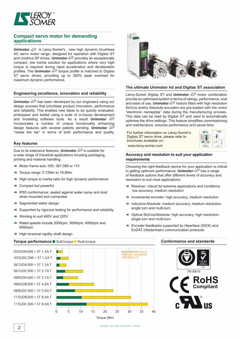
Torque performance ■ Stall torque ■ Peak torque Conformance and standards
Compact servo motor for demanding applications
Unimotor is Leroy-Somer's , new high dynamic brushless AC servo motor range, designed for operation with Digitax ST and Unidrive SP drives. Unimotor provides an exceptionally compact, low inertia solution for applications where very high torque is required during rapid acceleration and deceleration profi les. The Unimotor torque profi le is matched to Digitax ST servo drives, providing up to 300% peak overload for maximum dynamic performance.
Engineering excellence, innovation and reliability
Unimotor has been developed by our engineers using our design process that prioritises product innovation, performance and reliability. This enables new ideas to be quickly evaluated, prototyped and tested using a suite of in-house development and modelling software tools. As a result Unimotor incorporates a number of unique functionality enhancing design features with several patents pending. Unimotor “raises the bar” in terms of both performance and quality.
Key features
Due to its extensive features, Unimotor is suitable for a wide range of industrial applications incuding packaging, printing and material handling.
➜ Motor frame size: 055, 067,089 or 115
➜ Torque range: 0.72Nm to 18.8Nm
➜ High torque to inertia ratio for high dynamic performance
➜ Compact but powerful
➜ IP65 conformance: sealed against water spray and dust when mounted and connected
➜ Segmented stator design
➜ Supported by rigorous testing for performance and reliability
➜ Winding to suit 400V and 220V
➜ Rated speeds include 2000rpm, 3000rpm, 4000rpm and 6000rpm
➜ High torsional rigidity shaft design
The ultimate Unimotor hd and Digitax ST association
Leroy-Somer Digitax ST and Unimotor motor combination provide an optimised system in terms of ratings, performance, cost and ease of use. Unimotor motors fi tted with high resolution SinCos and/or Absolute encoders are pre-loaded with the motor “electronic nameplate” data during the manufacturing process. This data can be read by Digitax ST and used to automatically optimise the drive settings. This feature simplifi es commissioning and maintenance, ensures performance and saves time.
For further information on Leroy-Somer's Digitax ST servo drive, please refer to brochures available on: www.leroy-somer.com
Accuracy and resolution to suit your application requirements
Choosing the right feedback device for your application is critical in getting optimum performance. Unimotor has a range of feedback options that offer different levels of accuracy and resolution to suit most applications.
➜ Resolver: robust for extreme applications and conditions low accuracy, medium resolution
➜ Incremental encoder: high accuracy, medium resolution
➜ Inductive Absolute: medium accuracy, medium resolution, single turn and multi-turn
➜ Optical SinCos/Absolute: high accuracy, high resolution, single turn and multi-turn
➜ Encoder feedbacks supported by Hiperface (SICK) and EnDAT (Heidenhain) communication protocols
Unimotor hd data at 3000 rpm associated with Digitax ST
QUALITYMANAGEMENT
003
FM 30610
055UDA300 + ST 1.5A T
055UDC300 + ST 1.5A T
067UDA300 + ST 1.5A T
067UDC300 + ST 2.7A T
089UDA300 + ST 2.7A T
089UDB300 + ST 4.0A T
089UDC300 + ST 5.9A T
115UDB300 + ST 8.0A T
115UDC300 + ST 8.0A T
0 205 2510 3015 35 40
w w w . l e r o y - s o m e r . c o m 3
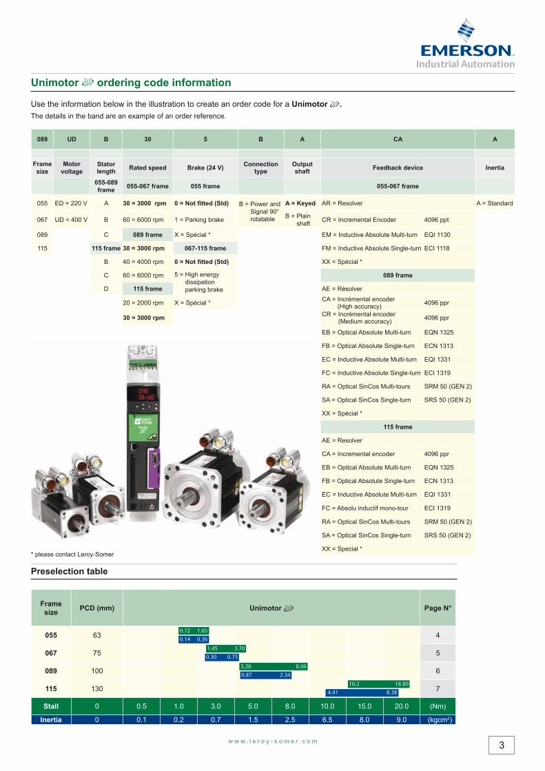
Preselection table
Frame size PCD (mm) Unimotor Page N°
055 63 4
067 75 5
089 100 6
115 130 7
Stall 0 0.5 1.0 3.0 5.0 8.0 10.0 15.0 20.0 (Nm)
Inertia 0 0.1 0.2 0.7 1.5 2.5 6.5 8.0 9.0 (kgcm2)
0.72
1.45
3.20
0.14
0.30
0.87
1.65
3.70
8.00
0.36
0.75
2.34
10.2
4.41
18.80
8.38
Unimotor ordering code information
Use the information below in the illustration to create an order code for a Unimotor .The details in the band are an example of an order reference.
089 UD B 30 5 B A CA A
Frame size
Motor voltage
Stator length Rated speed Brake (24 V) Connection
typeOutput shaft Feedback device Inertia
055-089 frame 055-067 frame 055 frame 055-067 frame
055 ED = 220 V A 30 = 3000 rpm 0 = Not fi tted (Std) B = Power and Signal 90° rotatable
A = Keyed AR = Resolver A = Standard
067 UD = 400 V B 60 = 6000 rpm 1 = Parking brake B = Plain shaft CR = Incremental Encoder 4096 ppt
089 C 089 frame X = Spécial * EM = Inductive Absolute Multi-turn EQI 1130
115 115 frame 30 = 3000 rpm 067-115 frame FM = Inductive Absolute Single-turn ECI 1118
B 40 = 4000 rpm 0 = Not fi tted (Std) XX = Spécial *
C 60 = 6000 rpm 5 = High energy dissipation parking brake
089 frame
D 115 frame AE = Résolver
20 = 2000 rpm X = Spécial * CA = Incrémental encoder (High accuracy) 4096 ppr
30 = 3000 rpm CR = Incrémental encoder (Medium accuracy) 4096 ppr
EB = Optical Absolute Multi-turn EQN 1325
FB = Optical Absolute Single-turn ECN 1313
EC = Inductive Absolute Multi-turn EQI 1331
FC = Inductive Absolute Single-turn ECI 1319
RA = Optical SinCos Multi-tours SRM 50 (GEN 2)
SA = Optical SinCos Single-turn SRS 50 (GEN 2)
XX = Spécial *
115 frame
AE = Resolver
CA = Incremental encoder 4096 ppr
EB = Optical Absolute Multi-turn EQN 1325
FB = Optical Absolute Single-turn ECN 1313
EC = Inductive Absolute Multi-turn EQI 1331
FC = Absolu inductif mono-tour ECI 1319
RA = Optical SinCos Multi-tours SRM 50 (GEN 2)
SA = Optical SinCos Single-turn SRS 50 (GEN 2)
XX = Special ** please contact Leroy-Somer
4 w w w . l e r o y - s o m e r . c o m
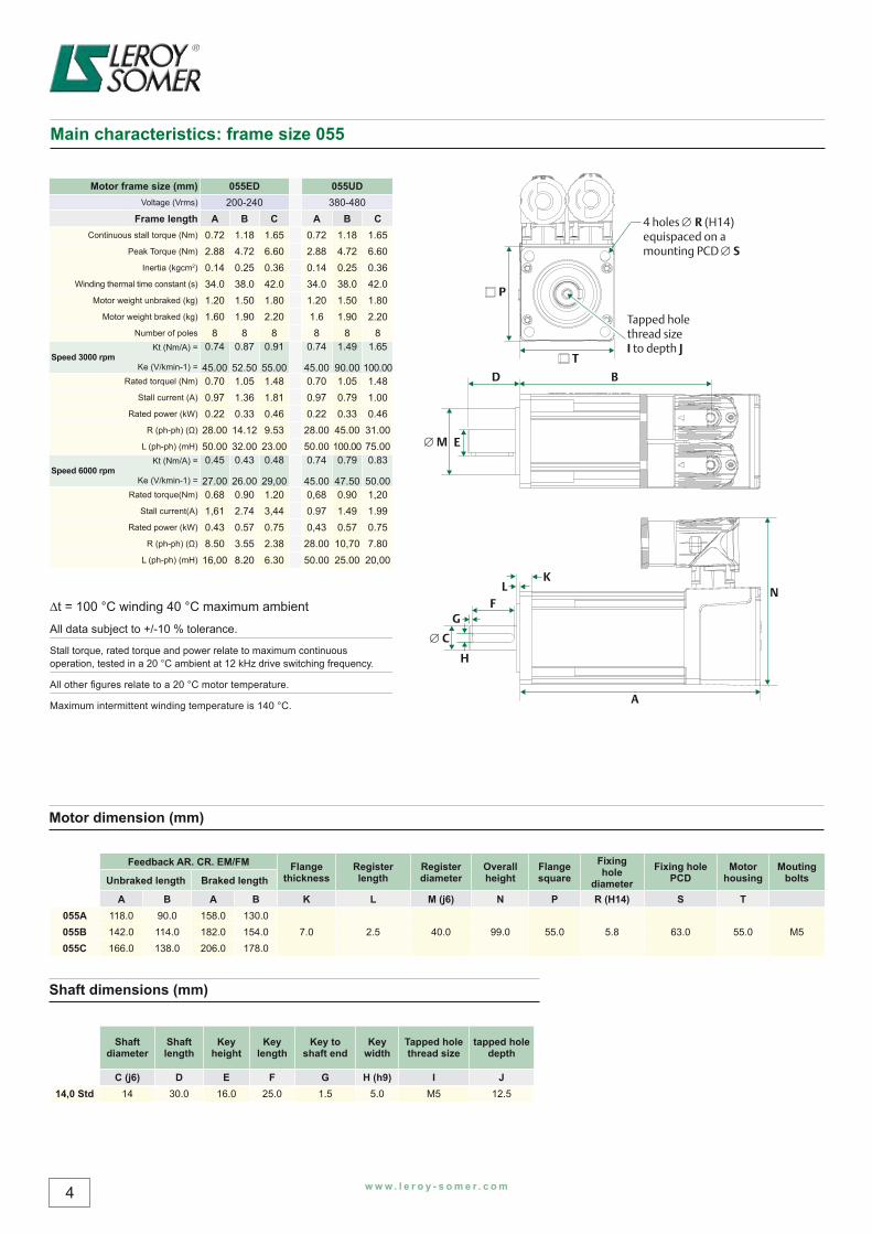
Motor frame size (mm) 055ED 055UDVoltage (Vrms) 200-240 380-480
Frame length A B C A B CContinuous stall torque (Nm) 0.72 1.18 1.65 0.72 1.18 1.65
Peak Torque (Nm) 2.88 4.72 6.60 2.88 4.72 6.60Inertia (kgcm2) 0.14 0.25 0.36 0.14 0.25 0.36
Winding thermal time constant (s) 34.0 38.0 42.0 34.0 38.0 42.0Motor weight unbraked (kg) 1.20 1.50 1.80 1.20 1.50 1.80
Motor weight braked (kg) 1.60 1.90 2.20 1.6 1.90 2.20Number of poles 8 8 8 8 8 8
Speed 3000 rpmKt (Nm/A) =
Ke (V/kmin-1) =
0.74
45.00
0.87
52.50
0.91
55.00
0.74
45.00
1.49
90.00
1.65
100.00Rated torquel (Nm) 0.70 1.05 1.48 0.70 1.05 1.48
Stall current (A) 0.97 1.36 1.81 0.97 0.79 1.00Rated power (kW) 0.22 0.33 0.46 0.22 0.33 0.46
R (ph-ph) (Ω) 28.00 14.12 9.53 28.00 45.00 31.00L (ph-ph) (mH) 50.00 32.00 23.00 50.00 100.00 75.00
Speed 6000 rpmKt (Nm/A) =
Ke (V/kmin-1) =
0.45
27.00
0.43
26.00
0.48
29,00
0.74
45.00
0.79
47.50
0.83
50.00Rated torque(Nm) 0.68 0.90 1.20 0,68 0.90 1,20
Stall current(A) 1,61 2.74 3,44 0.97 1.49 1.99Rated power (kW) 0.43 0.57 0.75 0,43 0.57 0.75
R (ph-ph) (Ω) 8.50 3.55 2.38 28.00 10,70 7.80L (ph-ph) (mH) 16,00 8.20 6.30 50.00 25.00 20,00
Main characteristics: frame size 055
Motor dimension (mm)
Feedback AR. CR. EM/FM Flange thickness
Register length
Register diameter
Overall height
Flange square
Fixing hole
diameterFixing hole
PCDMotor
housingMouting
boltsUnbraked length Braked length
A B A B K L M (j6) N P R (H14) S T055A 118.0 90.0 158.0 130.0
7.0 2.5 40.0 99.0 55.0 5.8 63.0 55.0 M5055B 142.0 114.0 182.0 154.0055C 166.0 138.0 206.0 178.0
Shaft dimensions (mm)
Shaft diameter
Shaft length
Key height
Key length
Key to shaft end
Key width
Tapped hole thread size
tapped hole depth
C (j6) D E F G H (h9) I J14,0 Std 14 30.0 16.0 25.0 1.5 5.0 M5 12.5
∆t = 100 °C winding 40 °C maximum ambient
All data subject to +/-10 % tolerance.
Stall torque, rated torque and power relate to maximum continuous operation, tested in a 20 °C ambient at 12 kHz drive switching frequency.
All other fi gures relate to a 20 °C motor temperature.
Maximum intermittent winding temperature is 140 °C.
FG
E
KL
A
N
H
C
M
BD
4 holes R (H14)equispaced on a mounting PCD S
P
T
Tapped hole thread sizeI to depth J
w w w . l e r o y - s o m e r . c o m 5
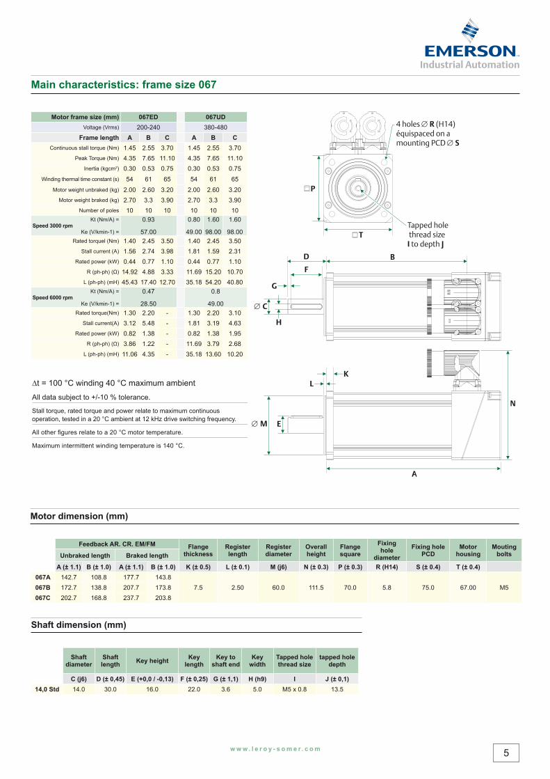
Shaft dimension (mm)
Shaft diameter
Shaft length Key height Key
lengthKey to
shaft endKey
widthTapped hole thread size
tapped hole depth
C (j6) D (± 0,45) E (+0,0 / -0,13) F (± 0,25) G (± 1,1) H (h9) I J (± 0,1)14,0 Std 14.0 30.0 16.0 22.0 3.6 5.0 M5 x 0.8 13.5
Main characteristics: frame size 067
Motor frame size (mm) 067ED 067UDVoltage (Vrms) 200-240 380-480
Frame length A B C A B CContinuous stall torque (Nm) 1.45 2.55 3.70 1.45 2.55 3.70
Peak Torque (Nm) 4.35 7.65 11.10 4.35 7.65 11.10Inertia (kgcm2) 0.30 0.53 0.75 0.30 0.53 0.75
Winding thermal time constant (s) 54 61 65 54 61 65Motor weight unbraked (kg) 2.00 2.60 3.20 2.00 2.60 3.20
Motor weight braked (kg) 2.70 3.3 3.90 2.70 3.3 3.90Number of poles 10 10 10 10 10 10
Speed 3000 rpmKt (Nm/A) =
Ke (V/kmin-1) =
0.93
57.00
0.80
49.00
1.60
98.00
1.60
98.00Rated torquel (Nm) 1.40 2.45 3.50 1.40 2.45 3.50
Stall current (A) 1.56 2.74 3.98 1.81 1.59 2.31Rated power (kW) 0.44 0.77 1.10 0.44 0.77 1.10
R (ph-ph) (Ω) 14.92 4.88 3.33 11.69 15.20 10.70L (ph-ph) (mH) 45.43 17.40 12.70 35.18 54.20 40.80
Speed 6000 rpmKt (Nm/A) =
Ke (V/kmin-1) =
0.47
28.50
0.8
49.00Rated torque(Nm) 1.30 2.20 - 1.30 2.20 3.10
Stall current(A) 3.12 5.48 - 1.81 3.19 4.63Rated power (kW) 0.82 1.38 - 0.82 1.38 1.95
R (ph-ph) (Ω) 3.86 1.22 - 11.69 3.79 2.68L (ph-ph) (mH) 11.06 4.35 - 35.18 13.60 10.20
4 holes R (H14)équispaced on a mounting PCD S
T
P
KL
A
N
EM
F
G
H
C
D
Tapped hole thread sizeI to depth J
B
Motor dimension (mm)
Feedback AR. CR. EM/FM Flange thickness
Register length
Register diameter
Overall height
Flange square
Fixing hole
diameterFixing hole
PCDMotor
housingMouting
boltsUnbraked length Braked length
A (± 1.1) B (± 1.0) A (± 1.1) B (± 1.0) K (± 0.5) L (± 0.1) M (j6) N (± 0.3) P (± 0.3) R (H14) S (± 0.4) T (± 0.4)067A 142.7 108.8 177.7 143.8
7.5 2.50 60.0 111.5 70.0 5.8 75.0 67.00 M5067B 172.7 138.8 207.7 173.8067C 202.7 168.8 237.7 203.8
∆t = 100 °C winding 40 °C maximum ambient
All data subject to +/-10 % tolerance.
Stall torque, rated torque and power relate to maximum continuous operation, tested in a 20 °C ambient at 12 kHz drive switching frequency.
All other fi gures relate to a 20 °C motor temperature.
Maximum intermittent winding temperature is 140 °C.
6 w w w . l e r o y - s o m e r . c o m
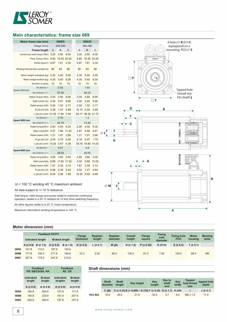
Main characteristics: frame size 089 Motor frame size (mm) 089ED 089UD
Voltage (Vrms) 200-240 380-480Frame length A B C A B C
Continuous stall torque (Nm) 3.20 5.50 8.00 3.20 5.50 8.00Peak Torque (Nm) 9.60 16.50 24.00 9.60 16.50 24.00
Inertia (kgcm2) 0.87 1.61 2.34 0.87 1.61 2.34
Winding thermal time constant (s) 85 93 98 85 93 98
Motor weight unbraked (kg) 3.30 4.40 5.50 3.30 4.40 5.50Motor weight braked (kg) 4.30 5.40 6.50 4.30 5.40 6.50
Number of poles 10 10 10 10 10 10
Speed 3000 rpmKt (Nm/A) =
Ke (V/kmin-1) =
0.93
57.00
1.60
98.00Rated torquel (Nm) 3.00 4.85 6.90 3.00 4.85 6.90
Stall current (A) 3.44 5.91 8.60 2.00 3.44 5.00Rated power (kW) 0.94 1.52 2.17 0.94 1.52 2.17
R (ph-ph) (Ω) 3.28 1.57 0.89 10.10 5.05 2.68L (ph-ph) (mH) 21.55 11.84 7.09 65.17 38.36 21.72
Speed 4000 rpmKt (Nm/A) =
Ke (V/kmin-1) =
0.70
42.75
1.2
73.50Rated torque(Nm) 2.90 4.55 6.35 2.90 4.55 6.35
Stall current(A) 4.57 7.86 11.43 2.67 4.58 6.67Rated power (kW) 1.21 1.91 2.66 1.21 1.91 2.66
R (ph-ph) (Ω) 2.04 0.79 0.54 6.16 2.47 1.75L (ph-ph) (mH) 13.20 5.97 4.38 39.78 18.80 14.03
Speed 6000 rpmKt (Nm/A) =
Ke (V/kmin-1) =
0.47
28.50
0.8
49.00Rated torque(Nm) 2.65 3.80 5.00 2.65 3.80 5.00
Stall current(A) 6.88 11.83 17.20 4.00 6.88 10.00Rated power (kW) 1.67 2.39 3.14 1.67 2.39 3.14
R (ph-ph) (Ω) 0.98 0.39 0.23 2.52 1.27 0.83L (ph-ph) (mH) 6.24 2.96 1.89 16.29 9.59 6.66
F
G
E
K
L
A
N
H
C
M
D
4 holes R (H14)équispaced on a
mounting PCD S
P
T
Tapped holethread sizeI to depth J
B
Motor dimension (mm)
Feedback EC/FC Flange thickness
Register length
Register diameter
Overall height
Flange square
Fixing hole
diameterFixing hole
PCDMotor
housingMouting
boltsUnbraked length Braked length
A (± 0.9) B (± 1.0) A (± 0.9) B (± 1.0) K (± 0.5) L (± 0.1) M (j6) N (± 1.0) P (± 0.28) R (H14) S (± 0.4) T (± 0.7)089A 147.8 110.5 187.9 150.6
10.3 2.20 80.0 130.5 91.0 7.00 100.0 89.0 M6089B 177.8 140.5 217.9 180.6089C 207.8 170.5 247.9 210.6
Shaft dimensions (mm)
Shaft diameter
Shaft length Key height Key
lengthKey to shaft end
Key width
Tapped hole thread
sizetapped hole
depth
C (j6) D (± 0,45)E (+ 0,009 / -0,134) F (± 0,25) G (± 1,1) H (h9) I J (± 0,1)19,0 Std 19.0 40.0 21.5 32.0 3.7 6.0 M6 x 1.0 17.0
Feedback FB. EB/CA/SA. RA
Feedback AE. CR
Unbraked length
Braked length
Unbraked lengthn
Braked length
A (± 0.9) A (± 0.9) A (± 0.9) A (± 0.9)089A 160.8 200.9 137.8 177.9089B 190.8 230.9 167.8 207.9089C 220.8 260.9 197.8 237.9
∆t = 100 °C winding 40 °C maximum ambient
All data subject to +/-10 % tolerance.
Stall torque, rated torque and power relate to maximum continuous operation, tested in a 20 °C ambient at 12 kHz drive switching frequency.
All other fi gures relate to a 20 °C motor temperature.
Maximum intermittent winding temperature is 140 °C.
w w w . l e r o y - s o m e r . c o m 7
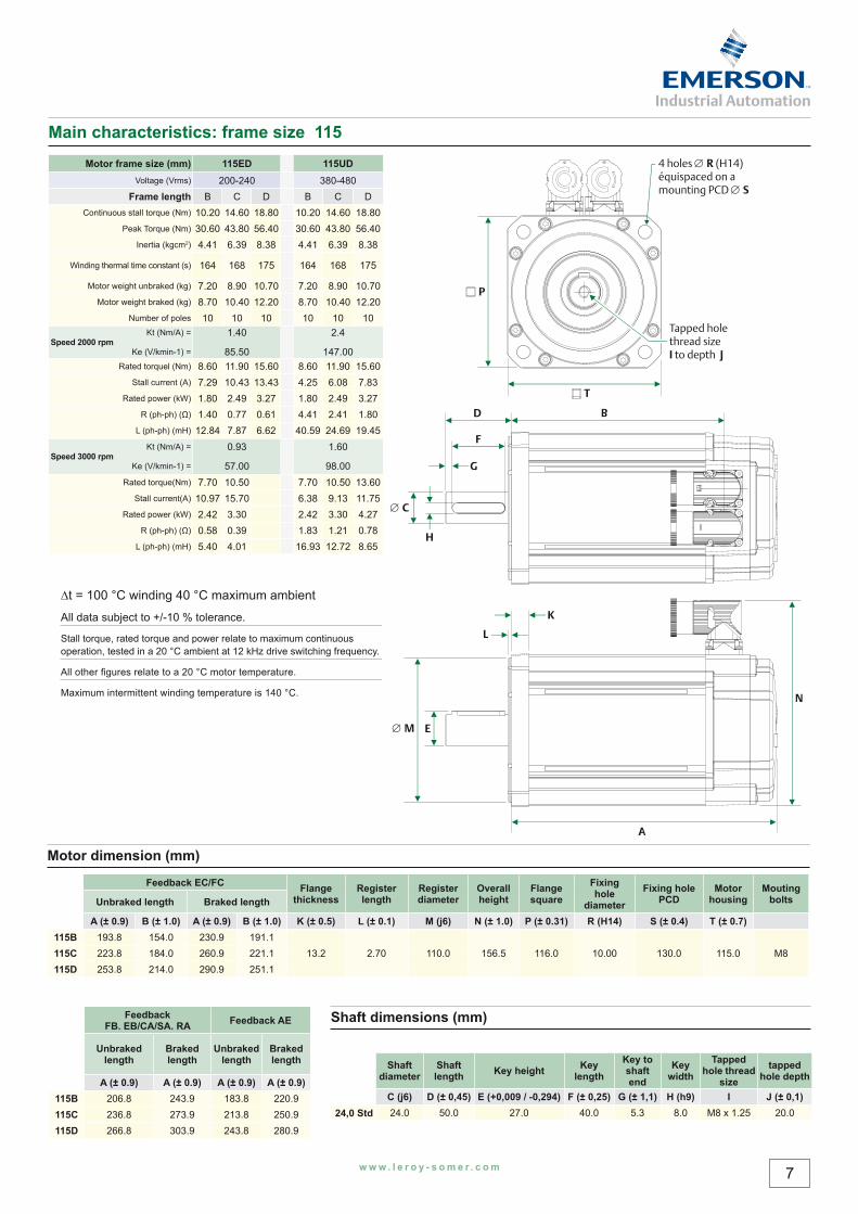
Main characteristics: frame size 115 Motor frame size (mm) 115ED 115UD
Voltage (Vrms) 200-240 380-480Frame length B C D B C D
Continuous stall torque (Nm) 10.20 14.60 18.80 10.20 14.60 18.80Peak Torque (Nm) 30.60 43.80 56.40 30.60 43.80 56.40
Inertia (kgcm2) 4.41 6.39 8.38 4.41 6.39 8.38
Winding thermal time constant (s) 164 168 175 164 168 175
Motor weight unbraked (kg) 7.20 8.90 10.70 7.20 8.90 10.70Motor weight braked (kg) 8.70 10.40 12.20 8.70 10.40 12.20
Number of poles 10 10 10 10 10 10
Speed 2000 rpmKt (Nm/A) =
Ke (V/kmin-1) =
1.40
85.50
2.4
147.00Rated torquel (Nm) 8.60 11.90 15.60 8.60 11.90 15.60
Stall current (A) 7.29 10.43 13.43 4.25 6.08 7.83Rated power (kW) 1.80 2.49 3.27 1.80 2.49 3.27
R (ph-ph) (Ω) 1.40 0.77 0.61 4.41 2.41 1.80L (ph-ph) (mH) 12.84 7.87 6.62 40.59 24.69 19.45
Speed 3000 rpmKt (Nm/A) =
Ke (V/kmin-1) =
0.93
57.00
1.60
98.00Rated torque(Nm) 7.70 10.50 7.70 10.50 13.60
Stall current(A) 10.97 15.70 6.38 9.13 11.75Rated power (kW) 2.42 3.30 2.42 3.30 4.27
R (ph-ph) (Ω) 0.58 0.39 1.83 1.21 0.78L (ph-ph) (mH) 5.40 4.01 16.93 12.72 8.65
D
F
G
E
4 holes R (H14)équispaced on amounting PCD S
P
T
Tapped hole thread sizeI to depth J
K
L
A
N
H
C
M
B
Motor dimension (mm)
Feedback EC/FC Flange thickness
Register length
Register diameter
Overall height
Flange square
Fixing hole
diameterFixing hole
PCDMotor
housingMouting
boltsUnbraked length Braked length
A (± 0.9) B (± 1.0) A (± 0.9) B (± 1.0) K (± 0.5) L (± 0.1) M (j6) N (± 1.0) P (± 0.31) R (H14) S (± 0.4) T (± 0.7)115B 193.8 154.0 230.9 191.1
13.2 2.70 110.0 156.5 116.0 10.00 130.0 115.0 M8115C 223.8 184.0 260.9 221.1115D 253.8 214.0 290.9 251.1
Shaft dimensions (mm)
Shaft diameter
Shaft length Key height Key
lengthKey to shaft end
Key width
Tapped hole thread
sizetapped
hole depth
C (j6) D (± 0,45) E (+0,009 / -0,294) F (± 0,25) G (± 1,1) H (h9) I J (± 0,1) 24,0 Std 24.0 50.0 27.0 40.0 5.3 8.0 M8 x 1.25 20.0
Feedback FB. EB/CA/SA. RA Feedback AE
Unbraked length
Braked length
Unbraked length
Braked length
A (± 0.9) A (± 0.9) A (± 0.9) A (± 0.9)115B 206.8 243.9 183.8 220.9115C 236.8 273.9 213.8 250.9115D 266.8 303.9 243.8 280.9
∆t = 100 °C winding 40 °C maximum ambient
All data subject to +/-10 % tolerance.
Stall torque, rated torque and power relate to maximum continuous operation, tested in a 20 °C ambient at 12 kHz drive switching frequency.
All other fi gures relate to a 20 °C motor temperature.
Maximum intermittent winding temperature is 140 °C.
8 w w w . l e r o y - s o m e r . c o m
Motor deratingAny adverse operating conditions require that the motor performance be derated. These conditions include; ambient temperature above 40°C, motor mounting position, drive switching frequency or the drive being oversized for the motor.
Ambient temperaturesThe ambient temperature around the motor must be taken into account. For ambient temperatures above 40°C the torque must be derated using the following formula as a guideline.
(Note: Only applies to 2000/3000 rpm speeds)
New derated torque = Specifi ed torque x √ [1-((Ambient temperature - 40°C) / 100)]
For example with an ambient temperature of 76°C the new derated torque will be 0.8 x specifi ed torque.
Mounting arrangementsThe motor torque must be derated if the motor mounting surface is heated from an external source such as a gearbox, the motor is connected to a poor thermal conductor, the motor is mounted with the connectors on the side or vertical, the motor is in a confi ned space with restricted air fl ow.
Drive switching frequencyMost Digitax ST / Unidrive SP nominal current ratings are reduced for the higher switching frequencies see Digitax ST or Unidrive SP manual for details.
See the table below for the motor de rate factors, these fi gures are for guidance only.(Note: Only applies to speeds up to 3000rpm)
Switching frequency
Motor type/frame 055 067 089 115
3 kHz 0.92 0.93 0.89 0.894 kHz 0.93 0.94 0.91 0.926 kHz 0.95 0.95 0.95 0.968 kHz 0.96 0.98 0.97 0.98
12/16 kHz 1 1 1 1
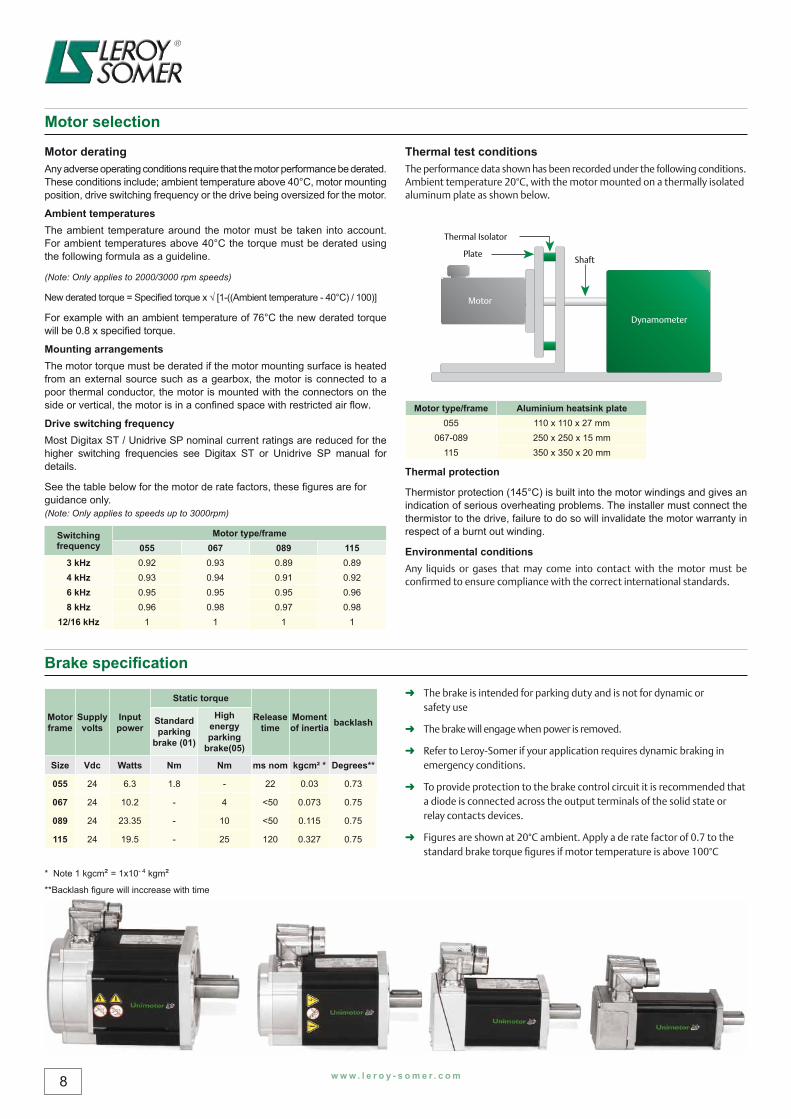
Thermal test conditionsThe performance data shown has been recorded under the following conditions. Ambient temperature 20°C, with the motor mounted on a thermally isolated aluminum plate as shown below.
Motor type/frame Aluminium heatsink plate055 110 x 110 x 27 mm
067-089 250 x 250 x 15 mm115 350 x 350 x 20 mm
Thermal protection
Thermistor protection (145°C) is built into the motor windings and gives an indication of serious overheating problems. The installer must connect the thermistor to the drive, failure to do so will invalidate the motor warranty in respect of a burnt out winding.
Environmental conditionsAny liquids or gases that may come into contact with the motor must be confi rmed to ensure compliance with the correct international standards.
Motor frame
Supply volts
Input power
Static torque
Release time
Moment of inertia backlashStandard
parking brake (01)
High energy parking
brake(05)
Size Vdc Watts Nm Nm ms nom kgcm² * Degrees**
055 24 6.3 1.8 - 22 0.03 0.73
067 24 10.2 - 4 <50 0.073 0.75
089 24 23.35 - 10 <50 0.115 0.75
115 24 19.5 - 25 120 0.327 0.75
* Note 1 kgcm² = 1x10- 4 kgm²**Backlash figure will inccrease with time
➜ The brake is intended for parking duty and is not for dynamic or safety use
➜ The brake will engage when power is removed.
➜ Refer to Leroy-Somer if your application requires dynamic braking in emergency conditions.
➜ To provide protection to the brake control circuit it is recommended that a diode is connected across the output terminals of the solid state or relay contacts devices.
➜ Figures are shown at 20°C ambient. Apply a de rate factor of 0.7 to the standard brake torque fi gures if motor temperature is above 100°C
PlateShaft
Motor
Dynamometer
Thermal Isolator
Brake specifi cation
Motor selection
w w w . l e r o y - s o m e r . c o m 9
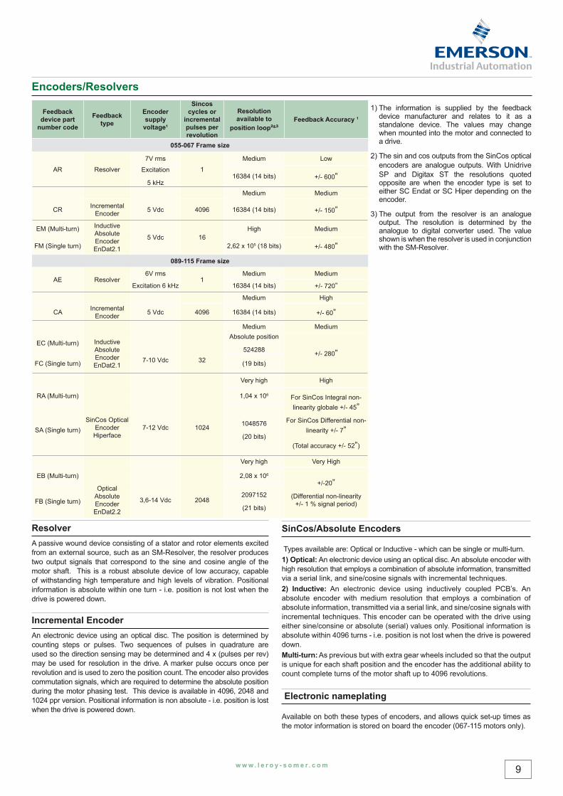
Feedback device part
number code
Feedback type
Encoder supply
voltage¹
Sincos cycles or
incremental pulses per revolution
Resolution available to
position loop²&³Feedback Accuracy 1
055-067 Frame size
AR Resolver
7V rms
1
Medium Low
Excitation
5 kHz16384 (14 bits) +/- 600”
Medium Medium
CR Incremental Encoder 5 Vdc 4096 16384 (14 bits) +/- 150”
EM (Multi-turn) Inductive Absolute Encoder EnDat2.1
5 Vdc 16High Medium
FM (Single turn) 2,62 x 10⁵ (18 bits) +/- 480”
089-115 Frame size
AE Resolver6V rms
1Medium Medium
Excitation 6 kHz 16384 (14 bits) +/- 720”Medium High
CA Incremental Encoder 5 Vdc 4096 16384 (14 bits) +/- 60”
Inductive Absolute Encoder EnDat2.1
7-10 Vdc 32
Medium Medium
EC (Multi-turn)Absolute position
524288 +/- 280”FC (Single turn) (19 bits)
SinCos Optical Encoder Hiperface
7-12 Vdc 1024
Very high High
RA (Multi-turn) 1,04 x 10⁶ For SinCos Integral non-linearity globale +/- 45”
For SinCos Differential non-linearity +/- 7”
(Total accuracy +/- 52”)
SA (Single turn)1048576
(20 bits)
Optical Absolute Encoder EnDat2.2
3,6-14 Vdc 2048
Very high Very High
EB (Multi-turn) 2,08 x 10⁶
+/-20”(Differential non-linearity
+/- 1 % signal period)FB (Single turn)2097152
(21 bits)
ResolverA passive wound device consisting of a stator and rotor elements excited from an external source, such as an SM-Resolver, the resolver produces two output signals that correspond to the sine and cosine angle of the motor shaft. This is a robust absolute device of low accuracy, capable of withstanding high temperature and high levels of vibration. Positional information is absolute within one turn - i.e. position is not lost when the drive is powered down.
Incremental EncoderAn electronic device using an optical disc. The position is determined by counting steps or pulses. Two sequences of pulses in quadrature are used so the direction sensing may be determined and 4 x (pulses per rev) may be used for resolution in the drive. A marker pulse occurs once per revolution and is used to zero the position count. The encoder also provides commutation signals, which are required to determine the absolute position during the motor phasing test. This device is available in 4096, 2048 and 1024 ppr version. Positional information is non absolute - i.e. position is lost when the drive is powered down.
SinCos/Absolute Encoders
Types available are: Optical or Inductive - which can be single or multi-turn.1) Optical: An electronic device using an optical disc. An absolute encoder with high resolution that employs a combination of absolute information, transmitted via a serial link, and sine/cosine signals with incremental techniques. 2) Inductive: An electronic device using inductively coupled PCB’s. An absolute encoder with medium resolution that employs a combination of absolute information, transmitted via a serial link, and sine/cosine signals with incremental techniques. This encoder can be operated with the drive using either sine/consine or absolute (serial) values only. Positional information is absolute within 4096 turns - i.e. position is not lost when the drive is powered down.Multi-turn: As previous but with extra gear wheels included so that the output is unique for each shaft position and the encoder has the additional ability to count complete turns of the motor shaft up to 4096 revolutions.
Electronic nameplating
Available on both these types of encoders, and allows quick set-up times as the motor information is stored on board the encoder (067-115 motors only).
1) The information is supplied by the feedback device manufacturer and relates to it as a standalone device. The values may change when mounted into the motor and connected to a drive.
2) The sin and cos outputs from the SinCos optical encoders are analogue outputs. With Unidrive SP and Digitax ST the resolutions quoted opposite are when the encoder type is set to either SC Endat or SC Hiper depending on the encoder.
3) The output from the resolver is an analogue output. The resolution is determined by the analogue to digital converter used. The value shown is when the resolver is used in conjunction with the SM-Resolver.
Encoders/Resolvers
10 w w w . l e r o y - s o m e r . c o m
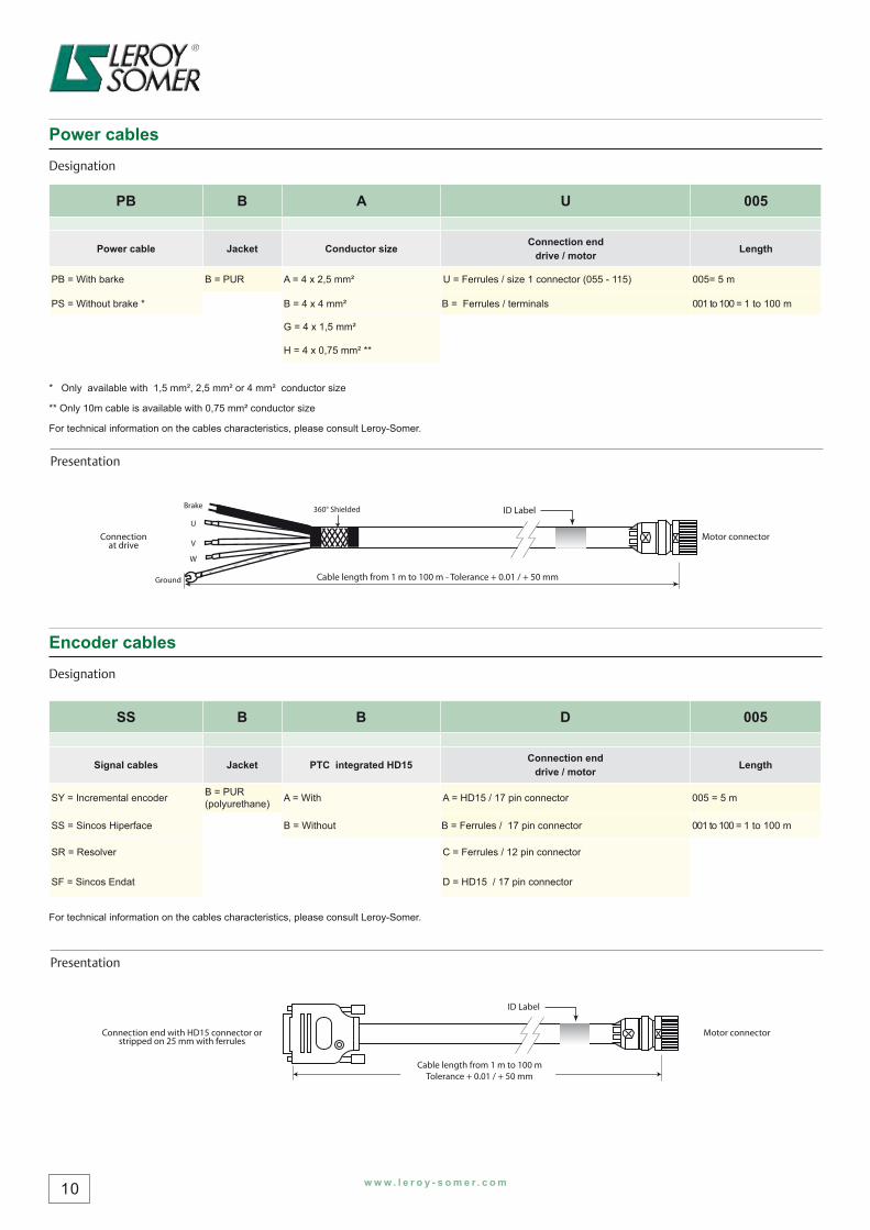
Power cables
Designation
PB B A U 005
Power cable Jacket Conductor size Connection end drive / motor Length
PB = With barke B = PUR A = 4 x 2,5 mm² U = Ferrules / size 1 connector (055 - 115) 005= 5 m
PS = Without brake * B = 4 x 4 mm² B = Ferrules / terminals 001 to 100 = 1 to 100 m
G = 4 x 1,5 mm²
H = 4 x 0,75 mm² **
* Only available with 1,5 mm², 2,5 mm² or 4 mm² conductor size
** Only 10m cable is available with 0,75 mm² conductor size
For technical information on the cables characteristics, please consult Leroy-Somer.
Presentation
ID Label
Motor connectorConnectionat drive
Cable length from 1 m to 100 m - Tolerance + 0.01 / + 50 mm
Brake
Ground
360° Shielded
W
V
U
Encoder cables
Designation
SS B B D 005
Signal cables Jacket PTC integrated HD15 Connection end drive / motor Length
SY = Incremental encoder B = PUR (polyurethane) A = With A = HD15 / 17 pin connector 005 = 5 m
SS = Sincos Hiperface B = Without B = Ferrules / 17 pin connector 001 to 100 = 1 to 100 m
SR = Resolver C = Ferrules / 12 pin connector
SF = Sincos Endat D = HD15 / 17 pin connector
For technical information on the cables characteristics, please consult Leroy-Somer.
Presentation
ID Label
Motor connectorConnection end with HD15 connector orstripped on 25 mm with ferrules
Cable length from 1 m to 100 mTolerance + 0.01 / + 50 mm
w w w . l e r o y - s o m e r . c o m 11
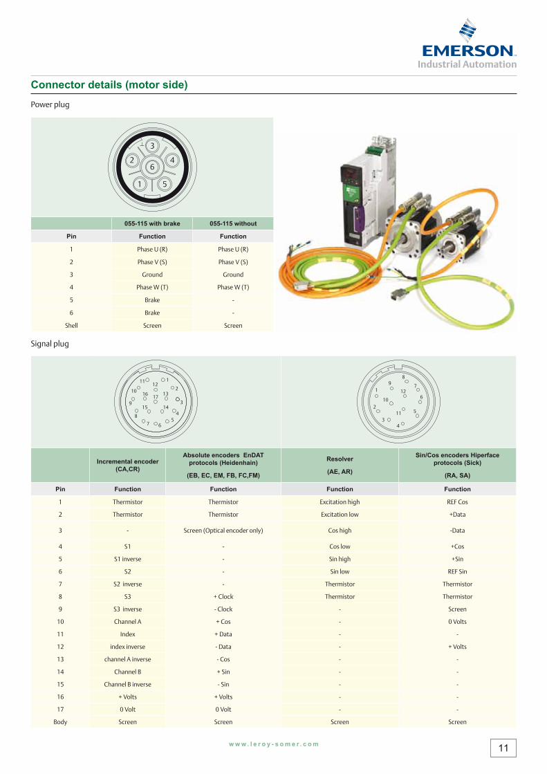
1 5
642
3
055-115 with brake 055-115 without
Pin Function Function
1 Phase U (R) Phase U (R)
2 Phase V (S) Phase V (S)
3 Ground Ground
4 Phase W (T) Phase W (T)
5 Brake -
6 Brake -
Shell Screen Screen
1
10
9
8
12
13
1415
1617
7 65
11
4
3
2 1
10
98
127
6
511
43
2
Incremental encoder (CA,CR)
Absolute encoders EnDAT protocols (Heidenhain)
(EB, EC, EM, FB, FC,FM)
Resolver
(AE, AR)
Sin/Cos encoders Hiperface protocols (Sick)
(RA, SA)
Pin Function Function Function Function
1 Thermistor Thermistor Excitation high REF Cos
2 Thermistor Thermistor Excitation low +Data
3 - Screen (Optical encoder only) Cos high -Data
4 S1 - Cos low +Cos
5 S1 inverse - Sin high +Sin
6 S2 - Sin low REF Sin
7 S2 inverse - Thermistor Thermistor
8 S3 + Clock Thermistor Thermistor
9 S3 inverse - Clock - Screen
10 Channel A + Cos - 0 Volts
11 Index + Data - -
12 index inverse - Data - + Volts
13 channel A inverse - Cos - -
14 Channel B + Sin - -
15 Channel B inverse - Sin - -
16 + Volts + Volts - -
17 0 Volt 0 Volt - -
Body Screen Screen Screen Screen
Connector details (motor side)
Power plug
Signal plug
Leroy-Somer reserves the right to modify the characteristics of its products at any time in order to incorporate the latest technological developments. The information contained in this document may therefore be changed without prior notice.
hh338 567 258 RCS ANGOULÊME - Limited company with capital of € 62,779,000
I n t e r n a t i o n a l n e t w o r k
ALGERIALEROY-SOMER International Division
AUSTRALIALEROY-SOMER PTY LTD
AUSTRIALEROY-SOMER ELEKTROMOTOREN
BELGIUMLEROY-SOMER BELGIUM
BRAZILLEROY-SOMER DIVISIONEMERSON ELECTRIC DO BRASIL ltda.
CANADALEROY-SOMER / EMC
CHINALEROY-SOMER Division
CROATIAEmerson Network Power Ltd
CZECH REPUBLIC M.L.S. HOLICE S.R.O.
DENMARKLEROY-SOMER DENMARK A/S
EGYPTMOTEURS LEROY-SOMER
FRANCEMOTEURS LEROY-SOMER
GERMANYLEROY-SOMER Marbaise GmbH
GREECELEROY-SOMER Ltd
HUNGARYLEROY-SOMER I.M.I.
INDIALEROY-SOMER C/O EMERSON ELECTRIC CO.
ITALIALEROY-SOMER SPA
JAPANLEROY-SOMER DIVISIONEMERSON Japan Ltd.
KOREAEMERSON ELECTRIC KOREA
MOROCCOCARREFOUR INDUSTRIEL ET TECHNOLOGIQUE
NETHERLANDSLEROY-SOMER NEDERLAND B.V
POLANDFZN MARBAISE LS
ROMANIALEROY-SOMER REPRESENTATIVE OFFICE
RUSSIALEROY-SOMER DIVISION
SAUDI ARABIAABUNAYYAN TRADING CORPORATION
SINGAPORELEROY-SOMER SOUTHEAST ASIA Pte Ltd
SOUTH AFRICALEROY-SOMER PTY LTD
SPAINLEROY-SOMER IBERICA S.A.
SWEDENLEROY-SOMER NORDEN AB
SWITZERLANDLEROY-SOMER SA
TAIWANLEROY-SOMER LIAISON OFFICE
THAILANDLEROY-SOMER THAILAND
TUNISIAULYSSE SPARE PARTS
TURKEYELEKTROMEKANIK SISTEMLER
U.A.E.LEROY-SOMER DIVISIONEMERSON FZE
UNITED KINGDOMLEROY-SOMER LTD
USA LEROY-SOMER POWER AND DRIVES
VENEZUELALEROY SOMER C/O EMERSON ELECTRIC CA
w w w . l e r o y - s o m e r . c o m
Leroy-Somer reserves the right to modify the chacharacracterterististics of its products at any time in ordeer tr to io inncorporate the latest technological developmenThe information contained in this document may therefore be changed without prior notice.
hh338 567 258 RCS ANGOULÊME - Limited company with capital of € 62,779,000