
LeROI Gas · PDF fileor air in a heat exchanger that is properly ... compressor from...
40
ISO 9001-2000 Installation – Operations Maintenance and Service Guide LeROI Gas Compressors By Rotary Compression Technologies, Inc. Rotary Screw Compressor Models: HG10 HGF10 HG12 HGF12 HGS17 HGSF17 HG17 HG24 LG30 LGL30 RCT-INST001 Rev 6 -8/08 ECN 48316
Transcript of LeROI Gas · PDF fileor air in a heat exchanger that is properly ... compressor from...

ISO 9001-2000
Installation – Operations Maintenance and Service Guide
LeROI Gas Compressors
By Rotary Compression Technologies, Inc.
Rotary Screw Compressor Models: HG10
HGF10 HG12
HGF12 HGS17
HGSF17 HG17 HG24 LG30
LGL30
RCT-INST001 Rev 6 -8/08 ECN 48316

ROTARY COMPRESSION TECHNOLOGIES, INC. THANKS YOU FOR PURCHASING LEROI GAS
COMPRESSORS, MODULES AND PARTS

Table of ContentsSafety Information and Warnings________ _________________1 Protecting Your Compressor Before Service_________________2 Identifying Your Compressor_____________________________3 Understanding Your Compressor_________________________4 The Compressor System______________________________5-6 Oil Flow and Orifice Sizing____________________________7-10 Variable Vi Adjustment______________________________11-13 Versatrol (Capacity Control)__________________________14-15 Oil and Related Items_________________________________16 Installation________________________________________17-18 Installation – Component Location________________________19 Operation and Preventive Maintenance____________________20 Service Procedures - Components_____________________21-29 Rebuild Kits_________________________________________30 Website____________________________________________31 Contact List_________________________________________32 Service Diagnosis____________________________________34 Warranty___________________________________________35

1
LeROI gas compressors are designed with safety in mind. However, there is no substitute
for safe operating procedures. Throughout this manual, there will be additional “Notes”,
“Cautions” and “Warnings” intended to protect the operator and the equipment. These
additions are not all inclusive. Extreme care must be exercised when operating or servicing
this equipment.
The operator and or serviceperson should:
• Be knowledgeable of one’s equipment.
• Develop safe work habits.
• Never operate a unit without guards and shields in place.
• Never operate a unit that is not properly electrically grounded.
• Never service a unit with the pressure in the receiver-oil reservoir unless
following specific operation manual instructions.
• Never service a unit without disconnecting and locking out the electrical
power supply unless following specific operation manual instructions.
• Take all necessary precautions, when adjusting controls, etc., to prevent
electrical shock.
• Take all necessary precautions when working with flammable gases to prevent
fire or explosion.
Safety Information and Warnings
A Careful Operator is the Best Insurance Against an Accident

2
THIS COMPRESSOR IS SHIPPED WITHOUT OIL. ALTHOUGH
RESIDUAL OIL FROM THE FACTORY TEST IS SUFFICIENT TO PREVENT
RUST DURING SHIPPING, IT DOES NOT PROVIDE ADEQUATE
PROTECTION FOR STORAGE.
IF THE COMPRESSOR WILL NOT ENTER SERVICE WITHIN ONE WEEK OF BEING
RECEIVED, COMPRESSOR OIL MUST BE ADDED THROUGH THE GAS INLET SO THAT
ITS LEVEL IS AT LEAST AS HIGH AS THE BOTTOM OF THE INLET CAVITY. ALLOW A
FEW MINUTES FOR THE OIL TO FILL INTERNAL CLEARANCES THEN ADD TO BRING
LEVEL BACK UP. REINSTALL THE INLET COVER PLATE AND BOLT IT DOWN
SECURELY. THE DRIVE SHAFT MUST BE ROTATED ½ TURN MONTHLY TO INSURE
THAT ALL MOVING PARTS HAVE AN OIL COATING.
Protecting Your Compressor Before Service

3
LeROI gas compressors have a nameplate that provides valuable information
on your compressor. This information is needed for ordering parts and
conversion kits, as well as for accessing warranty information and
understanding the design of the compressor. Below is a Model Designation
chart to help you identify your
compressor.
Identifying Your Compressor

4
Your compressor is either a LG (Low Pressure) or HG (High Pressure) single stage,
positive displacement, oil-flooded screw compressor. There are two basic general
configurations; geared (Figure 1) and non-geared (Figure 2).
Figure 1 - geared compressor Figure 2 -Typical non-geared compressor
Oil-flooding provides cooling, lubrication and sealing in the compressor. The oil must be cooled using either water or air in a heat exchanger that is properly sized for all operating conditions. Geared units (Figure 1) come standard with integral gearing to increase or decrease the speed internally, allowing for direct connection with standard drivers. The drive (input) shaft is an integral extension of the male rotor. Compressors with gears use an independent input shaft, commonly referred to as a jackshaft, mounted on roller and/or special deep groove ball bearings. The gear mounted on the jackshaft drives the gear mounted on the male rotor and the male rotor meshes with and drives the female rotor.
Figure 3 shows the direction of the rotor rotation and the gas/oil flow through the compressor. Note that this flow is between the rotors and the inside diameter (bore of the cylinder). The uncompressed gas enters the compressor at the inlet flange, passes into the front bearing retainer, and enters the cylinder bore at the front (inlet) end. (Figure 3). As the gas passes a predetermined inlet cut-off point in the cylinder, compression takes place due to decreasing rotor to cylinder volume as the rotors turn. Gas at the desired pressure is discharged at the rear (discharge) end. Oil is injected into the compressor at specific locations for cooling.
Understanding Your Compressor
Figure 3 - Oil/Gas Flow-Typical

5
The LeROI gas compressor is one part of the compressor system. The compressor combined with the
driver forms the heart of the system. However, the other vital elements are essential to ensure the heart
of your system continues to operate.
Suction Scrubber (with filtration, if necessary)
This is required to prevent the carry over of liquids into the compressor. Filtration is often necessary, especially in vacuum
installations, to prevent debris (e.g. iron sulfides) from getting into the compressor.
Gas/Oil Separator
The gas/oil separator is a key component of the compressor system. The separator should be designed to handle the
maximum capacity at the lowest discharge pressure and the highest discharge temperature. It is important that the vessel and
coalescing filter are sized properly to insure optimum gas and oil separation. The separator also acts as the oil reservoir (oil
sump), with the oil collecting in the bottom.
Oil Cooler
The oil cooler is an air-cooled or water-cooled heat exchanger that is sized to suit the size (capacity) of the compressor being
cooled. The cooler should be designed to handle the worst operating condition, which is usually based on the lowest suction
pressure and the highest discharge pressure. However, the oil flow plays a critical role in determining the heat rejection of the
oil cooler.
Minimum Pressure Valve
The minimum pressure valve is recommended to maintain a minimum pressure in the gas/oil seperator. It is especially
important to use this device when the possibility exists that the system pressure may not be sufficient to maintain pressure in
the seperator to achieve adequate gas/oil seperation.
Thermal By-Pass Valve
The injection temperature of the oil used to cool, seal, and lubricate the compressor is controlled by the thermal by-pass
valve. As the name implies, this valve allows part or all of the oil flow to by-pass the oil cooler, depending on the temperature
of the oil leaving the compressor. This valve can be controlled thermostatically or with more sophisticated temperature
control valve where more precise control of oil temperature is required.
The Compressor System
6
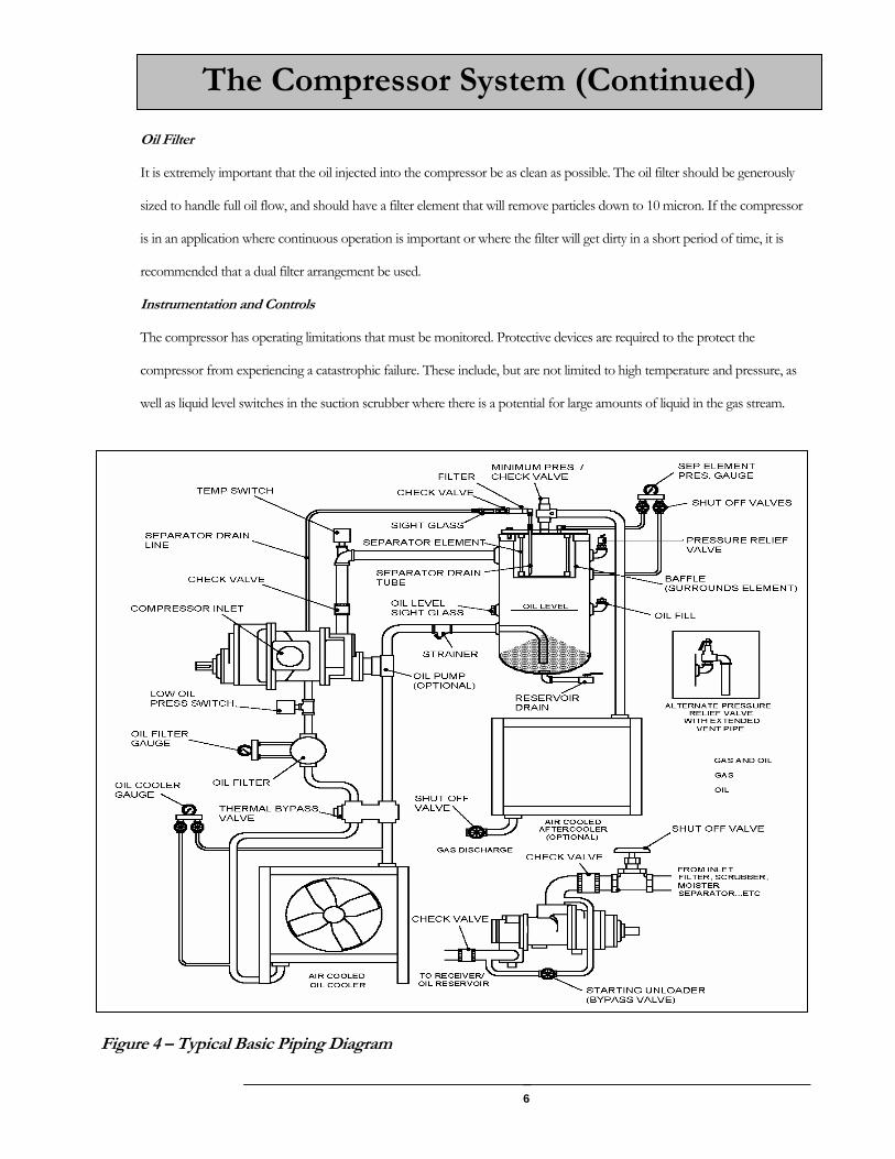
Oil Filter
It is extremely important that the oil injected into the compressor be as clean as possible. The oil filter should be generously
sized to handle full oil flow, and should have a filter element that will remove particles down to 10 micron. If the compressor
is in an application where continuous operation is important or where the filter will get dirty in a short period of time, it is
recommended that a dual filter arrangement be used.
Instrumentation and Controls
The compressor has operating limitations that must be monitored. Protective devices are required to the protect the
compressor from experiencing a catastrophic failure. These include, but are not limited to high temperature and pressure, as
well as liquid level switches in the suction scrubber where there is a potential for large amounts of liquid in the gas stream.
Figure 4 – Typical Basic Piping Diagram
The Compressor System (Continued)

7
As mentioned previously in this manual, rotary screw compressors require oil lubrication of
the bearings, cylinder and rotors. Bearing lubrication is necessary for long life. Cylinder and
rotor lubrication does three things:
1. Reduces friction between the rotors
2. Provides a seal between the cylinder and rotors to reduce gas slippage.
3. Cools the gas.
In certain applications the pressure differential (discharge-suction) is such that an oil pump is not required.
However, if the application has a lower pressure differential than an oil pump will be required. It is
important for the application to be reviewed especially if the unit will be moved from one site to another
resulting in different conditions.
LeROI gas compressors have an oil injection manifold that distributes oil supplied by the pump or pressure
differential. The orifice creates a restriction. A smaller orifice results in a greater restriction, which forces
more oil to the bearing and less oil to the rotors. The goal is to create a proper balance in the compressor
for reliable operation.
Oil Flow and Orifice Sizing
Figure 5 – Typical Oil Flow Figure 6 – Orifice Installation

8
Pumps are installed at the factory based on packager instructions or specified operating
conditions. Every LeROI compressor is tested at the factory to ensure reliable
operation. After testing, the standard orifice or an orifice specified by the customer is
installed in the unit.
IT IS ALWAYS GOOD PRACTICE TO VERIFY THAT THE PUMP AND ORIFICE
SELCTION ARE CORRECT FOR THE FIELD OPERATING CONDITIONS DURING
COMMISSIONING OF THE COMPRESSOR PACKAGE.
There are several size options for each compressor. In the event that an orifice is needed and one is not
readily available one can easily be created. Simply drilling a hole in a solid plug will provide the orifice. It is
also important to note that you may need to create an orifice in the event your desired size is in between
manufacturer available sizes.
Refer to Figure 7 for temperature and pressure methods and locations.
Gas discharge temperature range: 175-210 oF
(Temperature must be high enough to reduce condensation in separator tank.)
High temperature shut down: 230 oF
(Switch must be located between compressor discharge flange and separator tank inlet.)
WARNING! NEVER EXCEED 230oF DISCHARGE
Oil Flow and Orifice Sizing
Temperature/Viscosity/Pressure

9
For Most Situations:
Temperature rise - From oil injection to gas discharge: 30 – 40 o F
For heavy gas streams, a 30-40 °F temperature difference may not be possible
Temperature rise – From oil injection to discharge bearing oil drain: 15 oF
WARNING! NEVER EXCEED 20oF BEARING RISE
Oil pressure difference – gas inlet versus oil injection: 60-100 psi
(When gas discharge pressures are 50 psig or less, it may not be possible
to achieve 60 psig oil pressure. That is acceptable if all other specifications are met.)
Oil viscosity at injection temperature: 13-40 cSt
(Refer to oil supplier data for viscosity at actual injection temperature.)
Temperature/Viscosity/Pressure (Continued)

10
Equipment & Measurement Location
Although other permanent instrumentation is necessary for monitoring overall package performance, the following are specifically for the purpose of evaluating the pump and orifice size. Table 2 Instruments & Measurement Locations
Instrument Data Location Infrared (IR) temperature gun
a. oil injection temperature b. gas discharge temperature c. discharge bearing oil drain temperature
(A) pipe (B) pipe (C) tube (goes down on some models)
Pressure gage or transducer 1
d. gas inlet pressure (D) inlet pipe
Pressure gage or transducer 2
e. oil injection pressure
(E) injection manifold
Figure 7 -Temperature / Pressure Measurement Locations Although probes inserted directly in the gas or oil stream will give more accurate results, an infrared (IR) temperature gun is recommended for this procedure. Since a probe cannot be readily used on the discharge bearing drain, the IR gun will allow a better comparison. For best results when using an IR gun, slowly moving the IR gun over the item to obtain the highest temperature. Be careful not to pick up temperatures from background objects.
Temperature measurements at points A, B, and C should be made on sections of pipe or tube (not fittings) as close to the compressor as possible. Pressures at points D and E should be as close to the compressor as possible. There is typically an unused port on the oil injection manifold for E. Point D is located in the package inlet piping. If pressures are not taken at these specific locations, they should at least be located on the compressor side of any major restrictions such as a filter. WHEN TO CHANGE A PUMP OR ORIFICE
Field Evaluation of Pump & Oil Injection Orifice Size
B
A C
D
E
Larger pump or orifice is required. Use performance program to resize
Is gas disch temp more than 210 oF?
Reduce oil injection temp by changing cooler or thermostat
Is difference between gas disch & oil injection temp less than 30oF?
Smaller pump or orifice is required. Use performance program to resize
Is diff between bearing oil drain & oil injection temp more than 20oF? OR Is oil injection pressure less than 60 PSI above gas inlet? (see Note)
Install smaller injection orifice.
Yes
No
Yes
no
No
No
Is diff between bearing oil drain & oil injection temp less than 3°F? OR is oil injection pressure more than 100 PSI above inlet pressure?
Install larger injection orifice.
Yes
Yes
Note: When gas disch pressure is below 60 PSI it may not be possible to achieve 60 PSI oil pressure, even with the smallest orifice. This is acceptable if the bearing oil drain temp is within spec.
Is difference between gas disch & oil injection temp more than 40oF?
No
Is gas molecular weight high?
Yes OK
No

11
Variable Vi is used to minimize the power required by the compressor. It does not change flow directly, but can allow an increase in flow through more efficient use of power. Vi is the volume compression ratio of a compressor: V1 / V2. The internal Vi of the compressor is determined by the size of the discharge port. A small port causes gas to be released later in the compression cycle resulting in a higher internal Vi, while a larger port allows the gas to be released earlier in the cycle resulting in a lower internal Vi. The ideal Vi for an application can be calculated if the inlet and discharge pressures and k (Cp/Cv) of the gas are known. The compressor makes the most efficient use of power when the internal Vi equals the ideal Vi. For example, if the internal Vi is high but the ideal Vi is low, the gas is compressed to a pressure greater than the external pressure prior to being released. On the other hand, if the internal Vi is low but the ideal Vi is high, gas momentarily flows backward into the compressor and is re-compressed. Both of these scenarios result in wasted energy. The standard discharge housings of the HG17, HG24, LG30, and LGL30 compressors have a 4.4 Vi port, but are fitted with four valves that can be opened to increase the total size of the discharge port, so that the following internal Vi’s can be achieved. Vi = 4.4 (HIGH) All valves closed Vi = 3.0 (MEDIUM) Two inner valves opened (two outer valves closed) Vi = 1.9 (LOW) All valves opened Instructions
THE COMPRESSOR CAN BE VERY HOT! PROTECT YOUR SKIN WHEN ADJUSTING A RUNNING OR HOT COMPRESSOR.
DO NOT TIGHTEN VALVES. Valves are not intended to be closed or opened by tightening. Doing so may damage the valve and/or compressor rotors. The valve should only be turned until it “touches” the end of its stroke and then backed off about 1/16 of a turn.
The first item to be performed is to determine the ideal Vi of the application.
There are three ways to do this: (1) Trial and error – adjust the valves while monitoring horsepower draw. (2) Use the LeROI Screw Compressor Performance Program by alternatively selecting High, Medium, and Low Vi on the Compressor tab, and see which results in the lowest horsepower. (3) Calculate the ideal Vi mathematically (or from a spreadsheet calculator available from www.leroigas.com): Vi = (P2/P1)1/k
Variable VI Adjustment

12
P1 and P2 must be in PSIA, and be at the compressor inlet and discharge flanges. Be sure to account for package pressure drops, which decrease the inlet pressure and increase the discharge pressure at the compressor flanges. As a quick reference, for a typical natural gas with k = 1.26, the pressure ratios that correspond to available internal Vi’s are: Vi P2 / P1 4.4 6.5 3.0 4.0 1.9 2.2 Since there are three available internal Vi settings, each must cover a range of ideal application Vi’s:
Ideal Vi Select Internal Vi Greater than 3.5 HIGH (All valves closed) Greater than 2.5, but not greater than 3.5
MEDIUM (Inner valves open, Outer valves closed)
Less than or equal to 2.5 LOW (All valves opened) After Determining the appropriate Vi ratio perform the following steps to adjust the internal Vi ratio:
Figure 8: Compressor discharge end showing four closed Vi valves fitted with special locknut-thread protectors. Compressor models may also have an oil pump mounted above the two valves on the left. Figure 9: Remove locknuts with wrench before making adjustments. It is not necessary to remove the outer locknuts if only the inner valves are being adjusted. The model represented in the figure has a pump and is part of a package.

13
Figure 10: For MEDIUM Vi, turn the inner valves counterclockwise until they are fully out. DO NOT FORCE THE VALVES. Once they “touch” the end of their stroke reverse them by 1/16 of a turn. This also applies when closing valves. Figure 11: For LOW Vi, in addition to turning the valves for MEDIUM, turn the outer valves counterclockwise until they are fully out. DO NOT FORCE THE VALVES. Once they “touch” the end of their stroke reverse them by 1/16 of a turn. This also applies when closing valves. Figure 12: Reinstall and tighten locknuts just snugly while holding valves so they do not turn. The valve positions in this figure are low Vi. Note that all of the valves are out. PERIODICALLY LUBRICATE THE VALVE STEM THREADS WITH GREASE TO PREVENT RUST AND ALLOW FOR FUTURE ADJUSTMENT. Figure 13: The valves in this figure are in a MEDIUM Vi position (inner valves out, outer valves in). It is not possible to hold the outer valve while tightening the locknut – just tighten the locknut lightly to prevent jamming the valve.

14
Versatrol capacity control is used to regulate compressor flow and reduce power requirements. Versatrol consists of a set of pressure actuated valve assemblies mounted on the side of the compressor. When opened, these valves allow gas to leave the compression cycle and return to the compressor inlet prior to compression and delivery, thus reducing flow and horsepower. A valve is closed by applying actuating pressure and opened by releasing actuating pressure. This can be used to ramp up the compressor during start up. Start the compressor with all the ports open then close them. The by-pass valve assemblies are sometimes referred to as unloaders or pockets. Versatrol is available on the HG12 and larger models. Due to the small cylinder size, the HG12 has two valves and an external by-pass (Figure 14). All larger models have four valves with an internal by-pass (Figures 15 and 16).
Depending on actual operating conditions, Versatrol can reduce flow by approximately 50% and power by 25%. Versatrol can be operated in steps or stepless. Step Control - each valve is fully opened of closed. For each valve opened in sequence, capacity and power will be reduced by approximately 13% and 6% respectively. Stepless Control - each valve is positioned anywhere between fully opened and fully closed, thus throttling the by-pass and allowing infinitely variable flow control. Stepless control is achieved through the use of electronic controls, which monitors flow and power, and adjusts valve position. LeROI-RCT does not supply control systems, but they are commercially available.
Versatrol Capacity Control
Figure 14 - HG12 showing one of two Versatrol pockets. Second identical pocket is on the opposite side
Figure 15 –HG17 showing four Versatrol pockets. HG24 arrangement is the same (Pockets 2 and 4 are under the compressor)
Figure 16 –LG30 showing four Versatrol pockets. (Pockets on HG17 and HG 24 are on the other side)

15
Actuation: The Versatrol valves can be operated with pressurized air, gas or lubricating fluid depending on whether it is step or stepless control. The actuation pressure should be the same or nearly the same as the compressor discharge pressure. The valves should be opened in the 1-2-3-4 sequence and closed in the 4-3-2-1 sequence, except the HG12. The HG12 can be opened or closed in any sequence. Oil may be used for either step or stepless control. Oil taken from the gas/ oil separator or after the oil pump should have adequate pressure to allow Versatrol actuation. Oil should always be filtered prior to entering the control system. Air or gas can be used for step control systems only. Air and gas are compressible and will not allow accurate or quick control responses. Air can be used for stepless control systems without a problem. As mentioned previously, the valve is unloaded or opened by reducing the control pressure. When the control pressure is reduced the higher pressure inside of the compressor opens the valve. Therefore, it is important for the actuation pressure during the unloading stage to be lower than the cylinder pressure. To ensure this occurs, the Versatrol valve assembly should be vented to the cylinder inlet if actuated by gas or oil. If the air is used in the control system then it will have to be vented to the atmosphere.
NEVER UNDER ANY CIRCUMSTANCES VENT GAS OR OIL TO THE ATMOSPHERE An oversight that occasionally occurs is the testing of a compressor on air with a vacuum inlet. If the Versatrol valve is vented to atmospheric pressure, the valve frequently does not open because the pressure in the cylinder is less than atmospheric pressure.
Plumbing: Steel or stainless steel tubing and fittings should be used. Copper tubing is not recommended. Copper and gas can react and reduce the reliability of your system. Tubing runs should not be any longer than necessary in order to avoid reduced response times between controls and the Versatrol valves. Tubing should be 3/8”. Tubing size increases in importance in cold environments or when tubing runs exceed 4 feet. Control Valve Selection: Since actuating pressure is applied and released through the same port in the Versatrol assembly, it is necessary to use a valve that can be turned between the pressure source and a vent (cylinder for oil and gas, atmosphere for air). Generally, a three or a four-way valve is required. Three-way valves are a good choice for manually operated Versatrol. Four-way valves are best for automatic, stepless control systems.
Versatrol Capacity Control Continued
NEVER UNDER ANY CICUMSTANCES VENT AIR INTO A GAS COMPRESSOR

16
The lubrication system is vital for reliable operation of LeROI gas compressors. Following these guidelines about oil and related items will ensure years of reliable service.
Start-Up: Prior to start-up the compressor should be pre-lubed. Oil Filter: Check after first 100 hours. Change once a month if continuously operated or every 1000
hours otherwise. Filter must be changed with every oil change. At the minimum a differential pressure is recommended for the oil filter. A differential gauge with an alarm is advised.
Viscosity: The packager/user is responsible for selecting oil that is compatible with the gas, and can
maintain minimum viscosity at the operating conditions. The recommended viscosity is 15 centistokes regardless of the operating conditions. The minimum viscosity is 13 centistokes regardless of the operating conditions.
Oil viscosity greater than 15 centistokes can affect performance, especially horsepower.
Analysis: Oil should be analyzed on a regular basis. Oil should be checked once a week for the first
month, with at least two of those samples being analyzed. If the first month of samples is okay then the analysis can be reduced to once a month. Increases in water content and metals should be watched closely. All reputable oil suppliers and manufacturers will analyze oil samples at no charge.
Recirculation: It is important that the oil recirculates at least two times per minute, especially with heavier
hydrocarbon and water saturated gases. This keeps the oil temperature higher, thereby reducing the possibility of hydrocarbons condensing and affecting the viscosity of the oil, or having water condense and cause lubrication problems.
Strainer: When there is an oil pump, it is recommended that a Y-strainer be installed between the
separator and the suction to the pump It is recommended that a Y-strainer be installed downstream of where the oil leaves the
discharge bearing retainer, and where it is injected in the casing. This will reduce the possibility of a catastrophic failure if a bearing fails on the discharge end.
Coalescing: The coalescing element in the gas oil separator should be monitored with a differential
pressure gauge. This element should be changed as required. It should be checked at least once a year. It is important that the filter element have enough surface area to remove oil from the gas stream.
Gas Filtration: Gas filtration is recommended. Particulate in the gas stream can contaminate the oil and
cause premature failure. Temperature: Oil temperature in and out of the rear-bearing retainer should be checked regularly. If
differential is greater than 30°F, there may not be sufficient lubrication for that are. This could also be an indication of worn bearings.
Oil and Related Items

17
The compressor and prime mover must be mounted on a rigid frame so that the drive, piping, etc. are not subject to strain and/or misalignment. Mounting holes are provided to securely attach the compressor. The mounting surface must be a smooth, level surface that will support the weight of the compressor and handle the associated vibration. Shims must be installed between the frame and the mounting surface to eliminate strain on the frame. Adequate airflow for cooling must be provided. Uncontrolled recirculation (from unit to other source) of hot air must be prevented. Refer to figure 17 for a typical installation.
Installation
Figure 17 – Typical Installation

18
Drive: Several types of drive couplings may be used. However, direct flexible and universal joint types are recommended. When using a direct flexible coupling follow the coupling manufacturer’s instructions. As a general rule, for this type of coupling, the alignment should be as near “in line” as possible. In any case, coupling misalignment may not exceed 1/32” parallel and/or 2° angular misalignment. Refer to figure 18.
Installation (Continued)
Figure 18
Depending on the size of the compressor, it may be possible to belt drive the compressor. However, there is a limit to the power that each compressor can sustain. Refer below: HG10; 30 HP HGF10; 50 HP HG12; 50 HP HGF12; 50 HP HGSF17; 50 HP If the shaft horsepower exceeds these numbers then the compressor must have the pulley mounted on a “jack” or idler shaft. If the idler pulley has a ratio other than 1:1 you will need to ensure you have not exceeded the speed rating on the compressor
Figure 19
Figure 20
THE DRIVE COUPLING (COUPLING, SHAFT, BELTS) MUST BE COVERED BY A SUITABLE GUARD OR SHIELD. ALL GUARDS AND SHIELDS MUST BE IN PLACE WHEN OPERATING THE UNIT

19
The components (Figure 17) of a gas compressor system should be mounted on the frame to make servicing the unit as convenient as possible. Oil piping and hoses should be located and fastened to prevent accidental damage. All moving parts (coupling, belts, fans, etc) must have guards or shields installed. Compressor Inlet: The inlet piping must be clean and fitted with suitable filters, (scrubber,
moisture separator, etc.) to prevent foreign matter from entering the compressor. All piping and other components must be adequately supported. Provisions must also be made to install other components such as gages, valves, temperature measuring and pressure control devices.
Compressor Discharge: The discharge line between the compressor and the oil receiver must be as
large as permitted by the size of the compressor discharge opening. The discharge line must never be reduced in size. The discharge line should be as short as possible with the minimum number of bends and fittings.
A high discharge temperature shut down switch, wired into the prime mover controls, must be installed in the discharge line. This trip switch should have a maximum trip setting of 230°F. Provisions must also be made to install other components such as gauges, valves, temperature measuring and pressure control devices.
Separator out: The piping from the separator out (minimum pressure check valve) must be as large as permitted by the outlet port of the minimum pressure valve. The length must be as short as possible with the minimum number of bends and fittings.
The piping must be adequately supported and fastened securely. Provisions must be made to mount and connect other components in this
line such as aftercooler, valves, pressure and temperature sensing devices, etc.
Comp Instrumentation: Pressure gauges should be provided to monitor the pressure drop (restriction) across the oil filter element, separator element, and oil cooler.
A single gauge for each is recommended, with a manifold and shut off
valves, to red both upstream and downstream (inlet and outlet) pressures. This limits the possibility of gauge error affecting pressure readings.
Installation - Component Location

20
Satisfactory performance of a stationary screw compressor requires a good preventive maintenance program. The following information is provided as a guide for such a program. Start Up:
1. Service all equipment (filters, moisture separators, prime mover, etc.) following the equipment manufacturer’s instructions.
2. Drain condensate (water) from the oil reservoir. Close the drain valve securely when oil appears. 3. Check the compressor oil reservoir fluid level. Add oil as necessary to the correct level. Do not
overfill. 4. Make certain adequate ventilation and cooling water, if required, is provided. 5. Start the unit by actuating the electrical controls or starting the engine following the equipment
manufacturer’s instructions. 6. Observe the unit for leaks, unusual noise, vibration, etc. (Shutdown the unit and correct as
required.) 7. Observe all instrumentation for proper readings.
Shut Down:
1. Stop the prime mover following manufacturer’s instructions.
Preventive Maintenance:
1. Ensure the oil is properly maintained per the “Oil and Related Items” section of this manual. 2. Visually inspect the entire unit for leaks, loose hardware, etc. as often as feasible. Correct as
required. 3. Service all equipment (filters, moisture separators, etc.) following the manufacturer’s
instructions. 4. Drain water (condensate) from the oil reservoir. Close the drain valve securely when oil appears. 5. Check the compressor oil reservoir level. Add correct type of oil as required. Do not overfill. 6. With the unit running, observe the oil pressure gages and compare readings (filter in-filter out)
A difference in pressure readings of 15 PSI or more indicates that the filter element must be renewed.
7. With the unit running observe the gas pressure gauges and compare readings. A pressure drop across the separator element of 15 PSI or more indicates the separator element is restricted. If the restriction is caused by dirt or other foreign matter, renew the separator element.
Oil saturation can cause excessive restriction across a separator element. Always check the separator drain tube and line for restriction, the check valve (installation and condition) and clean or renew the drain line filter before condemning a separator element.
8. Remove surface dirt and dust from the oil cooler and after cooler.
Operation and Preventive Maintenance

21
BEFORE REMOVING ANY COMPONENTS SHUT THE UNIT DOWN, CLOSE ALL INLET AND DISCHARGE SHUTOFF VALVES, RELIEVE ALL PRESSURE BY “PUMPING OUT”. MAKE CERTAIN THE PRESSURE SYSTEM REMAINS VENTED TO ATMOSPHERE. DISABLE, LOCKOUT AND TAG THE PRIME MOVER.
Compressor Service: The compressor for these units is serviced only as a complete assembly using a new or factory rebuilt compressor. Parts available for field service include the input shaft rotary oil seal and the seal retainer gasket or o-ring seal. The compressor input shaft rotary seal may be replaced as follows, Refer to Figure 21: I. Make certain the unit cannot be started and system has all pressure removed. II. Remove any coupling guards and/ or shields. III. Clean the front of the compressor thoroughly to prevent dirt from entering the
compressor. IV. Disconnect the drive coupling.
If the compressor or prime mover must be unfastened from the frame, save and mark all mounting shims if any, for reuse.
NOTE: Always verify Seal Kit P/N by referring to appropriate compressor assembly / parts drawing. The seal kit includes: (1) Rotary shaft seal assembly (1) 100 grit silicon carbide emery cloth (1) Technical / Service Bulletin TSB0802 (1) Tube P80 Rubber Lubricant Emulson The following procedure is to be used for installing all rotary face type shaft seals: Follow the maintenance manual procedure for the specific unit being serviced, to expose the rotary seal retainer. Disconnect the lubrication line (tube) from the seal retainer or bearing retainer (depends on unit model). NOTE THE FITTING INSTALLED IN THE SEAL OR BEARING RETAINER OR THE OIL PASSAGE IN THE RETAINER, WHICH DELIVERS OIL TO THE SEAL, MAY BE RESTRICTED OR ORIFICED. INSPECT THIS FITTING AND OIL PASSAGE AND THE ATTACHING LINE (TUBE) TO MAKE CERTAIN THE ORIFICE IS CLEAN AND THAT THE TUBE HAS BEEN CORRECTLY INSTALLED (NO EXCESSIVE FITTING CRUSH).
Service Procedures - Components
Input Shaft Seal Replacement:
22
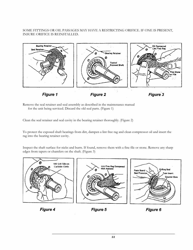
SOME FITTINGS OR OIL PASSAGES MAY HAVE A RESTRICTING ORIFICE. IF ONE IS PRESENT, INSURE ORIFICE IS REINSTALLED.
Remove the seal retainer and seal assembly as described in the maintenance manual for the unit being serviced. Discard the old seal parts. (Figure 1) Clean the seal retainer and seal cavity in the bearing retainer thoroughly. (Figure 2) To protect the exposed shaft bearings from dirt, dampen a lint free rag and clean compressor oil and insert the rag into the bearing retainer cavity. Inspect the shaft surface for nicks and burrs. If found, remove them with a fine file or stone. Remove any sharp edges from tapers or chamfers on the shaft. (Figure 3)
23
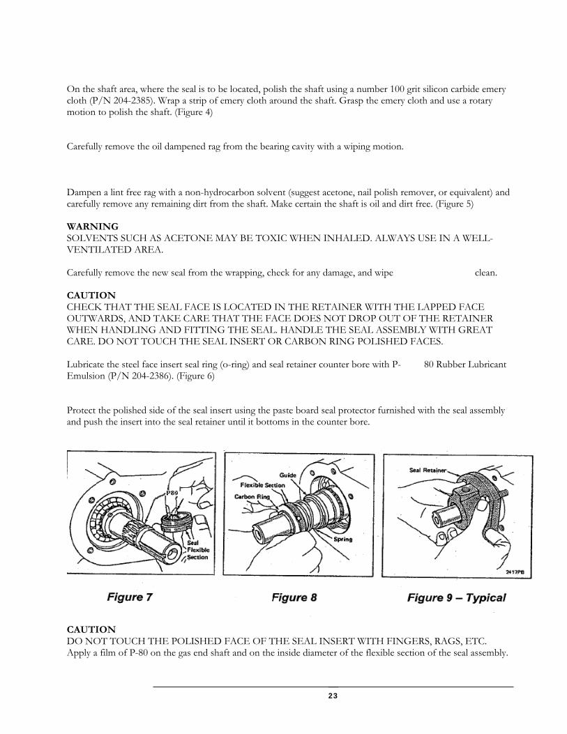
On the shaft area, where the seal is to be located, polish the shaft using a number 100 grit silicon carbide emery cloth (P/N 204-2385). Wrap a strip of emery cloth around the shaft. Grasp the emery cloth and use a rotary motion to polish the shaft. (Figure 4) Carefully remove the oil dampened rag from the bearing cavity with a wiping motion. Dampen a lint free rag with a non-hydrocarbon solvent (suggest acetone, nail polish remover, or equivalent) and carefully remove any remaining dirt from the shaft. Make certain the shaft is oil and dirt free. (Figure 5) WARNING SOLVENTS SUCH AS ACETONE MAY BE TOXIC WHEN INHALED. ALWAYS USE IN A WELL-VENTILATED AREA. Carefully remove the new seal from the wrapping, check for any damage, and wipe clean. CAUTION CHECK THAT THE SEAL FACE IS LOCATED IN THE RETAINER WITH THE LAPPED FACE OUTWARDS, AND TAKE CARE THAT THE FACE DOES NOT DROP OUT OF THE RETAINER WHEN HANDLING AND FITTING THE SEAL. HANDLE THE SEAL ASSEMBLY WITH GREAT CARE. DO NOT TOUCH THE SEAL INSERT OR CARBON RING POLISHED FACES. Lubricate the steel face insert seal ring (o-ring) and seal retainer counter bore with P- 80 Rubber Lubricant Emulsion (P/N 204-2386). (Figure 6) Protect the polished side of the seal insert using the paste board seal protector furnished with the seal assembly and push the insert into the seal retainer until it bottoms in the counter bore.
CAUTION DO NOT TOUCH THE POLISHED FACE OF THE SEAL INSERT WITH FINGERS, RAGS, ETC. Apply a film of P-80 on the gas end shaft and on the inside diameter of the flexible section of the seal assembly.

24
CAUTION TO MAKE CERTAIN THAT THE FLEXIBLE SECTION OF THE SEAL ADHERES TO THE SHAFT IN THE CORRECT LOCATION, IT IS NECESSARY TO COMPLETE THE ASSEMBLY ONCE STARTED. Lubricate the carbon ring section of the seal assembly with clean compressor oil. CAUTION DO NOT USE OTHER TYPES OF OIL OR GREASE. Make certain all parts and supplies (gasket, sealer, etc.) are available before beginning final assembly. Without touching the polished area of the carbon seal ring install the seal assembly (spring, etc.) on the shaft. (Figure 8) Apply sealer (or install gasket on the seal retainer) as described in the instruction manual for the unit being serviced. Immediately install the seal retainer and attaching capscrews to the bearing retainer mating surface. Tighten all capscrews securely. (Figure 9) After installation is completed allow the seal to sit without rotating the shaft for approximately 30 minutes. Complete reassembly of drive coupling, guard, etc. following instructions provided in the manual for the unit being serviced.

25
The minimum pressure valve may be purchased as an assembly if required. Service parts are available, however, to repair/overhaul this valve. This valve may be serviced as follows: 1. Make certain the unit cannot be started and that all the pressure has been removed from the
system. 2. Remove the service piping from the minimum pressure valve. 3. Remove the valve from the receiver-oil reservoir cap. 4. Securely clamp the valve in a vertical position (cap end up) in a suitable fixture (bench vise). 5. With a suitable wrench remove the valve cap from the valve body.
The spring beneath the cap is under pressure; exercise extreme care when removing the cap
Service Procedure Components
Figure 21-Compressor Input Shaft Seal Figure 22- Minimum Pressure Check Valve (Small)
Minimum Pressure/ Check Valve Service

26
6. Remove the spring from the body.
Save spring shim(s) (washers) (if any) for reuse. 7. Insert a suitable tool (wood stick) into the inlet port of the valve and push the piston and the valve
assembly upward and out of the body. 8. Remove the check valve piston from inside the larger piston. Take care not to lose the small
spring. 9. Remove the o-ring from the large piston and discard the o-ring. 10. Thoroughly clean all the remaining parts. Visually inspect all parts for damage or wear. Replace as
required. 11. Install a new o-ring on the large piston. 12. Reassemble the small check valve piston, with the spring, in the large piston. 13. Lubricate the o-ring on the piston with a silicone base lubricant. (Example: Dow Corning 55M). 14. Reinstall the check valve and piston assembly in the valve body. Take care not to damage the o-
ring during installation. 15. Install the large spring in the valve body on top of the piston. Reinstall spring shim(s). 16. Lightly coat the cap threads with “Loctite” 271 and install the cap (compress spring) by threading
the cap into the valve body. Torque the cap to 60-70 ft lbs. 17. Reinstall the minimum pressure valve on the receiver-oil reservoir cover. Use a good grade of pipe
thread sealer on all pipe threads. Tighten securely. Do not over tighten. 18. Reconnect the service piping to the valve using pipe thread sealer on the pipe threads. Tighten
service piping securely. Do not over tighten.
Service Procedure-Components
Figure 23- Minimum Pressure/Check Valve (Large)

27
This section contains the instructions to replace a high-pressure spring in a minimum pressure valve with a low-pressure spring. Figure 24 - MPV Parts. Figure 25 – Seated Piston Depth.
Approximately 7/8 inch from the top of the body. May be installed before or after spacers shown in figures 26 and 27.
Figure 26 – Installation of First Spacer. Figure 27 – Installation of remaining spacers. Marked “1”. Install “Down” side down Install 1 or 2 at a time to insure they slide in (chamfered to keep sharp edges from I.D. smoothly. Ten spacers are used for 40 PSI of piston) pressure.
Service Procedure-Components (Continued)
Changing Minimum Pressure Valve Spring
High Pressure Spring Cover
Body
Piston Spacer Stack
Low Pressure Spring

28
Figure 28 – Ten Spacers Installed in Piston. Figure 29 – Installation of Spring Part No. 24-810. Either end may be installed down. Figure 30 – Installation of Cover. Keep cover fairly level during installation, tightening bolt on either side a little at a time so cover does not tilt. Bolts should be tightened securely, but do not need to be torqued accurately (50 – 80 ft-lb is adequate).
Service Procedure-Components (Continued)
Changing Minimum Pressure Valve - Continued

29
An oil separator may be removed as follows: 1. Make certain the unit cannot be started and that all pressure has been removed from the system. 2. Disconnect the piping from the minimum pressure valve. 3. Disconnect the separator drain line and remove the drain tube from the separator. Mark the position
of the receiver-reservoir cover to aid in correct assembly. 4. Remove the separator cover to receiver-reservoir attaching capscrews (nuts) and remove the cover. 5. Remove the separator element by lifting it out of the reservoir. 6. Clean the cover and reservoir cover mounting flange. Make certain all traces of gasket material are
removed. If the gaskets do not have grounding staples, install two large copper clad staples in each gasket.
7. Inspect the new element gaskets to make certain the electrical grounding staples are installed. 8. Reinstall the separator element in the receiver-reservoir. 9. Reinstall the reservoir cover, correctly positioned, with attaching capscrews (nuts) and tighten
securely. 10. Reinstall the separator drain tube and fitting.
The drain tube must extend into the separator element far enough to touch the bottom of the element. If the tube is not long enough to touch bottom, obtain/make a new tube.
11. Reconnect the separator drain line.
MAKE CERTAIN THE DRAIN LINE FILTER AND CHECK VALVE ARE CORRECTLY INSTALLED
12. Reconnect the service piping to the minimum pressure valve. Use a quality pipe thread sealer on all
pipe threads. Tighten securely. Do not over tighten.
Oil Separator Service
Service Procedure-Components (Continued)
30
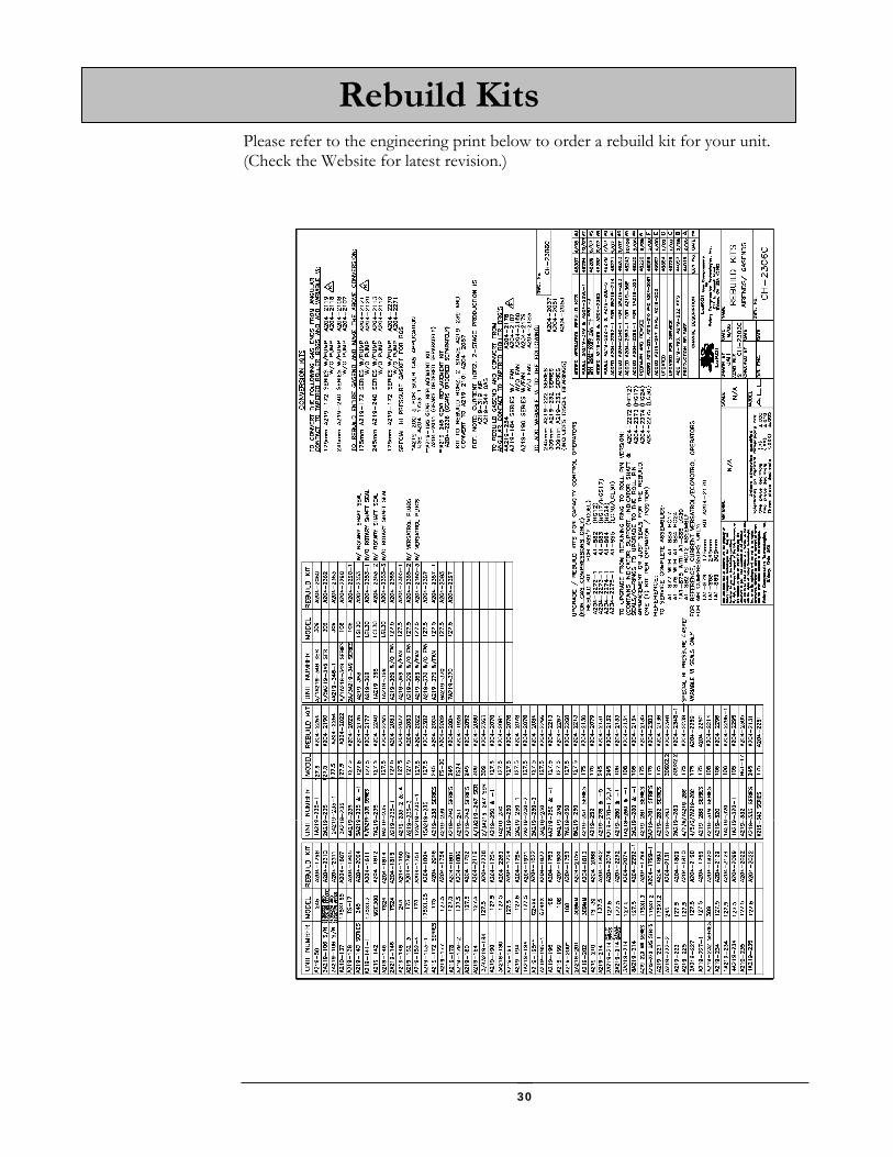
Please refer to the engineering print below to order a rebuild kit for your unit. (Check the Website for latest revision.)
Rebuild Kits

31
LeROI-RCT has a website that contains useful tips, features, sizing information, and technical data. We encourage using and exploring the website to learn what tools are available to you. Visit us at www.leroigas.com
Website

32
Below is a list of contacts in case you need any assistance. In order to provide you with the latest information this list is also available on the website: www.leroigas.com
USA Compressor Sales / Pricing / Applications / Specifications / Compressor Sizing Maro Johnson
Phone: 281-693-1950
Fax: 281-693-1952
Cell: 713-586-9005
Email: [email protected] or [email protected]
Compressor Orders & Shipping / Parts Orders & Shipping / Warranty Tina Edwards
Phone: 937-498-2550
Fax: 937-492-3424
Email: [email protected]
Note: All warranty claims now submitted via the web. Visit www.leroigas.com.
Engineering / Technical Support / Website Ron Keen
Phone: 937-498-2558
Fax: 937-492-3424
Email: [email protected]
Accounting Amanda Young
Phone: 937-498-2638
Fax: 937-492-3424
Email: [email protected]
Contact List

33
CANADA Compressor Sales / Pricing/ Applications/ Specifications / Compressor Sizing
Phone: 403-808-8377
Fax: 403-945-1910
Email: [email protected]

34
Service Diagnosis
MALFUNCTION PROBABLE CAUSE REMEDY High Discharge Temperature
1. Insufficient or incorrect oil. 2. Operating above rated pressure or at
excessive ratio. 3. Excessive inlet temperature. 4. Restricted oil cooler (inside or
outside). 5. Damaged or inoperative thermal by-
pass valve. 6. Restricted cooling oil flow.
1. Fill, or drain and re-fill oil reservoir to correct
level with correct oil. 2. Operate at correct pressures. 3. Lower inlet temperature. 4. Clean (inside and outside) or replace with
new cooler. 5. Service thermal by-pass valve. 6. a. Service oil filter.
b. Check oil lines and hoses for restrictions. Service as required.
Low Inlet Pressure
1. Improperly set inlet valve or other
control. 2. Restricted inlet (dirty or clogged filters,
screens, etc). 3. Damaged or faulty inlet pressure
regulator.
1. Set or adjust control correctly. 2. Service inlet filters or screens. 3. Service inlet pressure regulator.
High Inlet Pressure
1. Improperly set inlet valve or other
control.
1. Set or adjust control correctly.
High Discharge Pressure
1. Operating at higher than rated
pressure. 2. Damaged or worn discharge check
valve. 3. Incorrect minimum pressure valve
installed. 4. Damaged or worn minimum pressure
valve. 5. Excessive restriction in separator or
outlet piping.
1. Adjust to operate at rated pressure. 2. Service discharge check valve. 3. Install correct minimum pressure valve. 4. Service minimum pressure valve. 5. Correct cause of excessive restriction.
Excessive Oil Consumption
1. Incorrect oil installed in reservoir. 2. Reservoir over-filled. 3. External oil leaks. 4. Operating with discharge pressure too
low. 5. Drain tube missing, broken or not
touching bottom of separator element. 6. Worn, damaged, or restricted
separator element. 7. Clogged or restricted separator drain
line drain tube or filter.
1. Drain unit and install correct oil. 2. Drain to correct level. 3. Check for and correct all leaks. 4. Operate at rated pressure. 5. Replace drain tube with correct length tube. 6. Service separator element. 7. a. Service drain line filter.
b. Check condition and installation of drain line check valve. Clean or install correctly. Replace if worn. Service drain line as required.

35
ROTARY COMPRESSION TECHNOLOGIES, INC d.b.a. LEROI GAS COMPRESSORS
WARRANTY FOR ROTARY SCREW GAS ENDS USED IN NON-CONSUMER APPLICATIONS
O.E.M. & GAS
Manufactured
LeROI-RCT warrants its rotary screw compressor products and parts to be in compliance with their respective specifications and free from defects in materials and workmanship during a warranty period ending the earlier of (i) 12 months after the product start up date, or (ii) 18 months after the original date of shipment of the product by LeROI-RCT.
Remanufactured LeROI-RCT warrants its remanufactured rotary screw compressor products and parts to be in compliance with their respective specifications and free from defects in materials and workmanship during a warranty period ending the earlier of (i) 90 days after the product start up date, or (ii) 9 months after the original date of shipment of the product by LeROI-RCT. LeROI-RCT's only obligation under this warranty will be, at its election, to repair or replace any part determined to be non-conforming or defective during the applicable warranty period, including ground freight (Domestic USA only for overseas warranty) for the gas end. Labor to change out the gas end is not covered. THIS WARRANTY DOES NOT COVER CORROSION. THE OWNER/USER ASSUMES ALL OTHER RISKS, IF ANY, SUCH AS THE RISK OF ANY DIRECT, INDIRECT, INCIDENTAL OR CONSEQUENTIAL LOSS OR DAMAGES ARISING OUT OF THE USE OF, OR INABILITY TO USE, THE COMPRESSOR OR ANY PART. THIS WARRANTY IS MADE IN LIEU OF THE WARRANTIES OF MERCHANTABILITY, FITNESS FOR PARTICULAR PURPOSE, AND ALL OTHER WARRANTIES, EXPRESS OR IMPLIED, AND MAY NOT BE VARIED OR EXTENDED EXCEPT IN WRITING BY AN AUTHORIZED OFFICIAL OF LeROI-RCT.
Rotary Compression Technologies 211 East Russell Road
Sidney, Ohio 45373 Phone: 937-498-2555
Fax: 937-492-3424 [email protected]
www.leroigas.com Effective 9/2/05- Revised 8-10-07

36
THIS PAGE INTENTIONALLY BLANK

37
It Pays to Use Genuine LeROI Parts
Provided by Rotary Compression Technologies, Inc
Rotary Compression Technologies
211 East Russell Road Sidney, Ohio 45365
Phone: 937-498-2555 Fax: 937-492-3424 [email protected] www.leroigas.com