Leimeister, M. and Kolios, A. and Collu, M. (2018 ...
12
Leimeister, M. and Kolios, A. and Collu, M. (2018) Critical review of floating support structures for offshore wind farm deployment. Journal of Physics: Conference Series, 1104 (1). ISSN 1742-6588 , http://dx.doi.org/10.1088/1742-6596/1104/1/012007 This version is available at https://strathprints.strath.ac.uk/66455/ Strathprints is designed to allow users to access the research output of the University of Strathclyde. Unless otherwise explicitly stated on the manuscript, Copyright © and Moral Rights for the papers on this site are retained by the individual authors and/or other copyright owners. Please check the manuscript for details of any other licences that may have been applied. You may not engage in further distribution of the material for any profitmaking activities or any commercial gain. You may freely distribute both the url ( https://strathprints.strath.ac.uk/ ) and the content of this paper for research or private study, educational, or not-for-profit purposes without prior permission or charge. Any correspondence concerning this service should be sent to the Strathprints administrator: [email protected] The Strathprints institutional repository (https://strathprints.strath.ac.uk ) is a digital archive of University of Strathclyde research outputs. It has been developed to disseminate open access research outputs, expose data about those outputs, and enable the management and persistent access to Strathclyde's intellectual output. brought to you by CORE View metadata, citation and similar papers at core.ac.uk provided by University of Strathclyde Institutional Repository
Transcript of Leimeister, M. and Kolios, A. and Collu, M. (2018 ...

Leimeister, M. and Kolios, A. and Collu, M. (2018) Critical review of
floating support structures for offshore wind farm deployment. Journal
of Physics: Conference Series, 1104 (1). ISSN 1742-6588 ,
http://dx.doi.org/10.1088/1742-6596/1104/1/012007
This version is available at https://strathprints.strath.ac.uk/66455/
Strathprints is designed to allow users to access the research output of the University of
Strathclyde. Unless otherwise explicitly stated on the manuscript, Copyright © and Moral Rights
for the papers on this site are retained by the individual authors and/or other copyright owners.
Please check the manuscript for details of any other licences that may have been applied. You
may not engage in further distribution of the material for any profitmaking activities or any
commercial gain. You may freely distribute both the url (https://strathprints.strath.ac.uk/) and the
content of this paper for research or private study, educational, or not-for-profit purposes without
prior permission or charge.
Any correspondence concerning this service should be sent to the Strathprints administrator:
The Strathprints institutional repository (https://strathprints.strath.ac.uk) is a digital archive of University of Strathclyde research
outputs. It has been developed to disseminate open access research outputs, expose data about those outputs, and enable the
management and persistent access to Strathclyde's intellectual output.
brought to you by COREView metadata, citation and similar papers at core.ac.uk
provided by University of Strathclyde Institutional Repository

Content from this work may be used under the terms of the Creative Commons Attribution 3.0 licence. Any further distribution
of this work must maintain attribution to the author(s) and the title of the work, journal citation and DOI.
Published under licence by IOP Publishing Ltd
EERA DeepWind'2018, 15th Deep Sea Offshore Wind R&D Conference
IOP Conf. Series: Journal of Physics: Conf. Series 1104 (2018) 012007
IOP Publishing
doi:10.1088/1742-6596/1104/1/012007
1
Critical review of floating support structures for
offshore wind farm deployment
M Leimeister1,2, A Kolios1 and M Collu1
1 Cranfield University, Energy and Power, Bedfordshire MK43 0AL, United Kingdom2 Fraunhofer Institute for Wind Energy Systems IWES, 27572 Bremerhaven, Germany
E-mail: [email protected], [email protected]
Abstract. Floating structures enable offshore wind power deployment at numerous deep watersites with promising wind potential where bottom-fixed systems are no longer feasible. However,the large diversity in existing floater concepts slows down the development and maturingprocesses of floating offshore wind turbines. Thus, in this work, different floating supportstructures are assessed with respect to their suitability for offshore wind farm deployment.A survey is conducted to examine the capacities of selected floater types, grouped into tencategories, with respect to ten specified criteria focusing on wind farm deployment. By thismeans, a multi-criteria decision analysis (MCDA) is carried out, using the technique fororder preference by similarity to ideal solution (TOPSIS). With the individual scores of thedifferent systems, considering the weighting of each criterion, suitable concepts are identifiedand potential hybrid designs, combining advantages of different solutions, are suggested.
1. Introduction
Offshore wind energy is of high importance among renewable energies; however, most of the siteswith good wind resources are at deep water (>60 m). This makes up around 80% of Europeanseas [1], 60% of oceans in US [2], and 80% of Japanese oceans [1, 3, 4]. With floating offshorewind turbine (FOWT) systems, deep water sites with high potential for wind energy utilisationcan be deployed, making offshore wind power no longer limited to water depths up to ∼50 m.
More than 30 FOWT concepts have been proposed [1, 2]. However, this broad range of floatertypes being up to now investigated - either as research designs, under development, in prototypestage, or already in demonstration projects - inhibits fast achievement of high technology readi-ness levels (TRLs). Furthermore, less diversity in floating support structures would allow morefocused research, development of required infrastructure, specification and adaption of suppliersand manufacturers, as well as realisation of serial production [5]. Then, FOWTs could becomesoon cost-competitive with bottom-fixed offshore wind turbine systems. Thus, this work intendsto examine different floaters, emphasising their suitability for deployment in offshore wind farms.
As fundamental basis for this study, a literature review on FOWT support structures, theircharacteristics, and the state-of-the-art is conducted. The main classification and the widevariety of existing floater concepts are presented in section 2. For the assessment of floatingsupport structures (section 3), first, a SWOT (strengths, weaknesses, opportunities, and threats)analysis is carried out for the three main categories (subsection 3.1). This already indicates

EERA DeepWind'2018, 15th Deep Sea Offshore Wind R&D Conference
IOP Conf. Series: Journal of Physics: Conf. Series 1104 (2018) 012007
IOP Publishing
doi:10.1088/1742-6596/1104/1/012007
2
benefits and drawbacks of the technologies and, hence, supports the investigation of otherconcepts. On this basis, a set of criteria for assessing the potential of floating support structuresfor wind farm deployment is specified in subsection 3.2. The examined alternatives are defined insubsection 3.3. To obtain more meaningful results and to allow ranking of the different supportstructures, a MCDA (multi-criteria decision analysis) is carried out in subsection 3.4, basedon survey results and using the TOPSIS (technique for order preference by similarity to idealsolution) method. A short summary with conclusions and outlook is given in section 4.
2. Review of FOWT support structures
In 2015, FOWTs counted already over 30 types [1, 2]. This broad range and huge diversity ofare presented in subsection 2.2. Even if always new concepts and technologies are coming up,there are three main categories, which are introduced in the following subsection 2.1.
2.1. Main classification of floaters
Floating support structures can be categorised based on the primary mechanism adopted tofulfil the static stability requirements. There are three main stabilising mechanisms [5–7]:
• Ballast stabilisedHaving large ballast deep at the bottom of the floating structure moves the centre of gravityof the total system below the centre of buoyancy. This leads, when tilting the platform, toa stabilising righting moment which counteracts rotational displacements.
• Waterplane (or buoyancy) stabilisedThe waterplane area is the main contributor to the restoring moment of the floater. Havinga large second moment of area with respect to the rotational axis, either due to a largewaterplane area or due to smaller cross-sectional areas at some distance from the systemcentral axis, creates a stabilising righting moment in case of rotational displacement.
• Mooring stabilisedHigh tensioned mooring lines generate the restoring moment when the structure is inclined.
Figure 1. Stability triangle for floating structures,adapted from [7].
Spars, semi-submersibles or barges,and tension leg platforms (TLPs)rely, respectively, on the above men-tioned stabilising mechanisms andthus make up the three cornerstonesof floating support structures. Thisis visualised in figure 1 in form of astability triangle.
Spars, the ballast stabilised floaters(figure 2a), usually consist of a longcylindrical structure which is filledwith ballast at the bottom. For sta-tion keeping, the floater is commonlyequipped with three catenary moor-ing lines. The same mooring systemis used for semi-submersibles, shownin figure 2b. To obtain waterplane-based stability, this floater type ismade out of three columns placed onthe edges of a triangle. The wind
EERA DeepWind'2018, 15th Deep Sea Offshore Wind R&D Conference
IOP Conf. Series: Journal of Physics: Conf. Series 1104 (2018) 012007
IOP Publishing
doi:10.1088/1742-6596/1104/1/012007
3
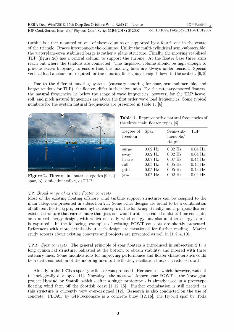
turbine is either mounted on one of these columns or supported by a fourth one in the centreof the triangle. Braces interconnect the columns. Unlike the multi-cylindrical semi-submersible,the waterplane-area stabilised barge is rather a plane structure. Finally, the mooring stabilisedTLP (figure 2c) has a central column to support the turbine. At the floater base three armsreach out where the tendons are connected. The displaced volume should be high enough toprovide excess buoyancy to ensure that the mooring lines are always under tension. Specialvertical load anchors are required for the mooring lines going straight down to the seabed. [6, 8]
Due to the different mooring systems (catenary mooring for spar, semi-submersible, andbarge; tendons for TLP), the floaters differ in their dynamics. For the catenary-moored floaters,the natural frequencies lie below the range of wave frequencies; however, for the TLP heave,roll, and pitch natural frequencies are above the first order wave load frequencies. Some typicalnumbers for the system natural frequencies are presented in table 1. [6]
Figure 2. Three main floater categories [9]: a)spar, b) semi-submersible, c) TLP.
Table 1. Representative natural frequencies ofthe three main floater types [6].
Degree offreedom
Spar Semi-sub-mersible/Barge
TLP
surge 0.02 Hz 0.02 Hz 0.04 Hzsway 0.02 Hz 0.02 Hz 0.04 Hzheave 0.07 Hz 0.07 Hz 0.44 Hzroll 0.05 Hz 0.05 Hz 0.43 Hzpitch 0.05 Hz 0.05 Hz 0.43 Hzyaw 0.02 Hz 0.02 Hz 0.04 Hz
2.2. Broad range of existing floater concepts
Most of the existing floating offshore wind turbine support structures can be assigned to themain categories presented in subsection 2.1. Some other designs are found to be a combinationof different floater types, termed hybrid concepts in the following. Finally, multi-purpose floatersexist: a structure that carries more than just one wind turbine, so-called multi-turbine concepts,or a mixed-energy design, with which not only wind energy but also another energy sourceis captured. In the following, examples of existing FOWT concepts are shortly presented.References with more details about each design are mentioned for further reading. Marketstudy reports about existing concepts and projects are presented as well in [1, 2, 4, 10].
2.2.1. Spar concepts The general principle of spar floaters is introduced in subsection 2.1: along cylindrical structure, ballasted at the bottom to obtain stability, and moored with threecatenary lines. Some modifications for improving performance and floater characteristics couldbe a delta-connection of the mooring lines to the floater, vacillation fins, or a reduced draft.
Already in the 1970s a spar-type floater was proposed - Heronemus - which, however, was nottechnologically developed [11]. Nowadays, the most well-known spar FOWT is the Norwegianproject Hywind by Statoil, which - after a single prototype - is already used in a prototypefloating wind farm off the Scottish coast [1, 12–15]. Further optimisation is still needed, asthis structure is currently very over-designed [12]. Research is also conducted on the use ofconcrete: FLOAT by GH-Tecnomare is a concrete buoy [12, 16], the Hybrid spar by Toda
EERA DeepWind'2018, 15th Deep Sea Offshore Wind R&D Conference
IOP Conf. Series: Journal of Physics: Conf. Series 1104 (2018) 012007
IOP Publishing
doi:10.1088/1742-6596/1104/1/012007
4
Construction uses steel at the upper and concrete at the lower section [1], the UniversitatPolitecnica de Catalunya designed an one-piece concrete structure for tower and floater [1], andwithin the Kabashima Island Project in Japan a hybrid (concrete/steel) spar floater is developed[2, 3]. Even some advanced spars, modified for improved performance, exist already. The delta-connection, also called crowfoot connection, of the mooring lines to the structure is often used,as well as redundant mooring lines, as for example for the double taut leg buoy by MIT [5].More advanced improvements, such as reduced draft or stabilising fins for improving sway andheave response, are integrated in the advanced spar floater within the Fukushima-FORWARDFloating Project in Japan by Japan Marine United [1, 3, 17]. Finally, some quite different sparfloaters are developed to support a vertical axis wind turbine (VAWT). In these designs, such asthe SeaTwirl by SeaTwirl Engineering in Sweden [1] or the DeepWind Spar by the DeepWindConsortium [1], the support structure is rotating together with the turbine.
2.2.2. Semi-submersible concepts The semi-submersible floater is explained in subsection 2.1.In addition to the catenary-moored three- or four-cylindrical structure, heave plates are oftenattached to the bottom of the columns to reduce heave motion. Further improvements withrespect to stability can be achieved by designing the geometry for wave-cancellation or by usingan active ballast system [18]. A braceless design would simplify manufacturing and inspection.
The floating structure developed within the Fukushima-FORWARD Floating Project inJapan by Mitsui Engineering & Shipbuilding [1, 3, 17, 18], as well as WINFLO in France [12, 18],VolturnUS by the DeepCwind Consortium [1], Drijfwind or FloatWind from the Netherlands[12, 18, 19], and VERTIWIND in France by Technip and Nenuphar for a VAWT [1], represent thebasic semi-submersible type with three or four columns, braces, and catenary moorings. Somesimplified floaters without braces are the Dutch Tri-Floater by GustoMSC [1, 5, 20], SeaReed byDCNS [1], OO-Star Wind Floater in Norway by Olav Olsen [21], SPINFLOAT by EOLFI fora VAWT [1], and TetraFloat by TetraFloat - a special light-weight design of the entire FOWTsystem [1]. As well braceless, but more innovative are the V-shape semi-submersible of theJapanese Fukushima-FORWARD Floating Project by Mitsubishi Heavy Industries [1, 3, 17, 18]and Nezzy SCD by Aerodyn Engineering, which is a turret-moored Y-shaped structure but usesplastic-composite buoys instead of cylindrical columns [1]. Active ballast system is additionallyused in the NAUTILUS concept by NAUTILUS Floating Solutions [1, 22] and the WindFloatby Principle Power in Portugal [1, 12, 15, 18, 23, 24].
2.2.3. Barge concepts Just as a semi-submersible, a barge floater is a waterplane-area stabilisedstructure. The main difference between these floaters, however, is that a semi-submersible hasdistributed buoyancy and consists of columns, while a barge is typically flat without interspaces.
Only a few barge-type FOWT systems exist. ITI Energy Barge [13] is very standard. Floatgenby the French Ideol, however, is quite special with its concrete ring-shaped support structureutilising a moonpool, also called damping pool, system for motion reduction [1, 18, 25].
2.2.4. TLP concepts The TLP system is explained in subsection 2.1. As a TLP is most re-liant on the tendons and highly dependent on the soil conditions, improvements can be achievedthrough redundant mooring lines and different, more soil-insensitive, anchors.
An early design is the Eolomar ring-shaped TLP [12]. More contemporary and very basicis the TLP by MIT and NREL [12, 13, 20]. GICON in Germany with GICON-SOF [1, 26],the American Glosten Associates with PelaStar [1, 15], Iberdrola with TLPWind [1, 27], andI.D.E.A.S with the TLWT [23] have addressed the high risk problem by equipping the floater

EERA DeepWind'2018, 15th Deep Sea Offshore Wind R&D Conference
IOP Conf. Series: Journal of Physics: Conf. Series 1104 (2018) 012007
IOP Publishing
doi:10.1088/1742-6596/1104/1/012007
5
with additional mooring lines, either via an increased number of arms or a supporting redundantmooring system. The strong soil dependence is solved by DBD Systems (Eco TLP) [1], Arcadis inGermany [12], and the Dutch Blue H Group (BlueH) [1, 12, 28] with (concrete) gravity anchors.
2.2.5. Hybrid concepts Combination of any of the three stability mechanisms, represented byspar, semi-submersible or barge, and TLP in figure 1, leads to so-called hybrid floating concepts.In this way, advantages of different systems can be combined in one floating structure.
Quite common is the tension leg buoy (TLB), which is a spar floater moored with tendons,such as the Floating Haliade by Alstom in France [10], the Ocean Breeze by Xanthus Energyin UK [10], the TLB series by the Norwegian University of Life Science [23], and the SWAYor Karmoy in Norway [1, 12, 23]. Nautica Windpower in the US combined in the single-pointmoored AFT (advanced floating turbine) a TLP with a semi-submersible to support a two-bladedwind turbine [1], while Concept Marine Associates added to a TLP a barge-shaped structure,which is ballasted offshore and, thus, functions as gravity-based anchor [5].
2.2.6. Multi-turbine concepts Placing more than one wind turbine on top of one floater reducesthe structural mass [1], as well as the mooring and anchoring costs per turbine, and increasesthe stability [20]. On the other hand, the loads on the structure might increase, the overallsize is enlarged, which complicates manufacturing and handling, and the turbines are likely tooperate sometimes in the wake of the other turbine(s) [1, 20]. This needs to be considered whendesigning a support structure for multi-turbine utilisation.
Two turbines are deployed on Hakata Bay Scale Pilot Wind Lens by the Japanese KyushuUniversity [3], while the semi-submersibles MUFOW (multiple unit floating offshore windfarm)[12, 16] and the design by Lagerwey and Herema [12] support several turbines. Hexicon byHexicon in Sweden carries three turbines in a row [1] and WindSea by FORCE Technology inNorway is a tri-floater with two upwind and one downwind turbine [1, 12].
2.2.7. Mixed-energy concepts Another option of higher utilisation of one floating support struc-ture is to capture not only wind but also another energy source, such as wave, current, tidal,or solar energy. This way, the power density can be increased and the fluctuations in the powerproduction can be balanced to some extent. However, as for the multi-turbine floater, the com-plexity and overall dimension of the system, as well as the loads on the system are increased [1].
Such multi-energy floaters are examined in the TROPOS, MERMAID, H2OCEAN, andMARINA projects [10, 29]. A quite common combination is wind and wave energy, as realised byW2power in Norway with the Pelagic Power floater [1] and by Floating Power Plant in Denmarkwith the Poseidon P80 semi-submersible [1]. Wind and ocean current turbines are combined inthe SKWID (Savonius keel & wind turbine Darrieus) by MODEC in Japan [1, 3]. Finally, themulti-turbine floater Hakata Bay Scale Pilot Wind Lens accommodates also solar panels [1, 3].
3. Assessment of floating support structures
The assessment of different floating support structures is carried out in two steps: first(subsection 3.1), a basic SWOT analysis is performed for the three main floater categoriesmentioned in subsection 2.1, and secondly (subsection 3.4), a MCDA is carried out. The criteria,focussing on the potential for offshore wind farm deployment, as well as the selected floaterconcepts used in the MCDA, are defined and specified beforehand in subsections 3.2 and 3.3,respectively. Based on the results of the MCDA, the TRLs and potentials to scale up to serialproduction for multi-MW wind farm deployment are estimated at the end (subsection 3.5).

EERA DeepWind'2018, 15th Deep Sea Offshore Wind R&D Conference
IOP Conf. Series: Journal of Physics: Conf. Series 1104 (2018) 012007
IOP Publishing
doi:10.1088/1742-6596/1104/1/012007
6
3.1. SWOT analysis
Based on the initially performed literature study the benefits and drawbacks of spars, semi-submersibles, and TLPs are presented in form of a SWOT analysis (tables 2 and 3).
Table 2. SWOT analysis of floater concepts - strengths and weaknesses.
Type Strengths Weaknesses
spar • inherent stability [1–3, 5, 6, 8, 18, 30,31]• suitable for even higher sea states [5]• soil condition insensitivity [5, 8]• cheap & simple mooring & anchoringsystem [6, 18, 20]• low operational risk [3]• little susceptible to corrosion [5]• simple structure, easy manufacturing& maintenance [1, 2, 5, 6, 8]
• relative large motions [12]• unsuitable for shallow water [1–6, 8,12, 30, 31]• large seabed footprint [2]• long mooring lines (costs) [5]• assembly in sheltered deep water [2,3, 8, 18]• challenging, time-consuming & costlyfloat-out & installation [1–3, 5, 8, 18]• long & heavy structure (costs) [5, 6]• high fatigue loads in tower base [2]
semi-sub-mersible
• heave plates for reducing heave re-sponse [2, 18]• broad weather window for float-out &installation [5]• depth independence [1, 2, 5, 6, 8, 12,30, 31]• soil condition insensitivity [2, 5, 8]• cheap & simple mooring & anchoringsystem [5, 6, 18, 20]• low overall risk [8, 32]• onshore or dry dock assembly [5, 6, 8,18]• simple installation & decommission-ing [1, 2, 5, 8, 12, 30]
• lower stability, higher motions [2, 3, 5,8, 30, 31]• wave sensitivity• large seabed footprint [2]• long mooring lines (costs) [5]• subject to corrosion & ice-loads [2, 5,6, 8, 20]• large & complex structure, more chal-lenging manufacturing & maintenance[1, 2, 6, 8]• large & heavy structure (costs) [1, 5,6, 8, 12]• larger impact on turbine due to mo-tions [2, 5, 8, 30, 31]
TLP • high stability, low motions [1–3, 6, 8,12, 18, 20]• little wave sensitivity (in case ofsubmerged platform) [30, 31]• suitable for even high sea states (incase of submerged platform) [5]• suitable for intermediate depths [2, 12]• small seabed footprint [2, 5, 6, 8, 20]• short mooring lines [5, 8]• little susceptible to corrosion (in caseof submerged platform) [5]• simple, small & light structure, easymaintenance [1, 2, 6]• onshore or dry dock assembly [1, 2]
• unsuitable for strong tidal currents orstorm surges [2–6, 8]• unsuitable for shallow water• unsuitable for challenging soil condi-tions [2–6, 8]• complex & costly mooring & anchor-ing system [1, 5, 8, 18, 20]• high risk if tendon or anchor fails [1,3, 6, 12, 18]• complex & risky installation & discon-nection for onshore maintenance [1, 2, 5,6, 8, 12, 18, 20, 30, 31]• large stresses in structure [1, 5]

EERA DeepWind'2018, 15th Deep Sea Offshore Wind R&D Conference
IOP Conf. Series: Journal of Physics: Conf. Series 1104 (2018) 012007
IOP Publishing
doi:10.1088/1742-6596/1104/1/012007
7
Table 3. SWOT analysis of floater concepts - opportunities and threats.
Type Opportunities Threats
spar • serial fabrication, synergies withtower manufacturing [1, 2, 5, 6, 8]• delta-connection for yaw stabilisation• stabilising fins for sway & heavestabilisation [1, 4]• horizontal transportation [5]• high TRL [8]
• special purpose vessels required [8]• no global market [8]
semi-sub-mersible
• cost reduction through mass produc-tion [8] & braceless design• geometry for wave-cancellation [6, 18]• stabilising active ballast system [1]• high TRL [8]• large global market [8]• may carry more than one turbine [6]
• large internal forces if geometrydesigned for wave-cancellation [6]• costly active ballast system [1]• high competition [8]
TLP • low mass production cost [8]• redundant moorings reduce risk• less soil dependent gravity anchors• low competition [8]
• special purpose installation shipsrequired [8]• low TRL [8]• no global market [8]
3.2. Set of criteria
FOWT support structures can be assessed based on different criteria, as done in [6, 30, 31, 33–35]. This study, however, focuses on offshore wind farm deployment. Thus, the following tencriteria are specified (table 4), with a (+)/(-) indicating a positive/negative criterion, meaningthat a higher score corresponds, respectively, to a more positive/negative aspect for the floater.
Table 4. Set of criteria.
Criterion Included aspects Type
1. LCOE levelised cost of energy (LCOE), rate of return, power density,outer dimension, mooring footprint, turbine spacing
(-)
2. volume pro-duction
ease of manufacturing, modular structure, fabrication time,onshore fabrication
(+)
3. ease of han-dling
outer dimension, total weight, assembly, transport, installation,decommissioning, required equipment and vessels
(+)
4. durability corrosion resistance, fatigue resistance, redundancy, aging (+)5. flexibility offshore site, water depth, soil condition, environmental loading (+)6. certification time to achieve, ease to achieve, TRL (+)7. performance deflections, displacements, nacelle acceleration, dynamic re-
sponse, overturning resistance, torsion resistance(+)
8. maintenance frequency, redundant components, costs, downtime (-)9. time-efficiency assembly, transport, installation, maintenance, decommissioning (+)
10. mooringrequirements
number of mooring lines, motions wrt need of flexible cables,length of lines, anchoring system costs
(-)

EERA DeepWind'2018, 15th Deep Sea Offshore Wind R&D Conference
IOP Conf. Series: Journal of Physics: Conf. Series 1104 (2018) 012007
IOP Publishing
doi:10.1088/1742-6596/1104/1/012007
8
3.3. Set of alternatives
The assessed floaters are specified in table 5 according to the categorisation in subsection 2.2.
Table 5. Set of alternatives.
Alternative Description
I. spar - standard common spar floater typeII. spar - advanced improved spar (reduced draft, vacillation fins, crowfoot/delta
mooring connection, horizontal transportation methodology)III. semi-submersible
- standardcommon semi-submersible floater type
IV. semi-submersible- advanced
improved semi-submersible (braceless, wave-cancelling geome-try, inclined/shape-optimised columns, active ballast system)
V. barge floater common barge floater typeVI. TLP - standard common TLP floater typeVII. TLP - advanced improved TLP (redundant mooring lines, gravity anchors)VIII. hybrid floater mixed spar, semi-submersible, TLP floater typesIX. multi-turbine floater floater supporting more than one wind turbineX. mixed-energy floater floater for wind & wave/tidal/current/photovoltaic utilisation
3.4. MCDA via TOPSIS
Several approaches, such as weighted sum or product methods (WSM/WPM), TOPSIS, an-alytical hierarchy process (AHP), ELECTRE (elimination et choix traduisant la realite), andPROMETHEE (preference ranking organization method for enrichment evaluation) can be usedto rank alternatives, taking account of multiple criteria. Based on studies applying and compar-ing MCDAmethods for the assessment of offshore wind turbine support structures [30, 31, 34, 35],TOPSIS is selected in this work, as it is based on easy, robust calculation methods, deals withcriteria of quantitative or qualitative nature, and incorporates expert opinions [31, 35]. Thebasis of TOPSIS is a set of alternatives and criteria, as specified in subsections 3.2 and 3.3. Bymeans of a survey, scores for each criterion are assigned to each alternative, in this study from1 (least applicable) to 5 (most applicable), and weights are set to represent the importance ofeach criterion with respect to offshore wind farm deployment, here again values between 1 (notimportant) and 5 (important). The scores yield a decision matrix, which is - after normalisation- multiplied with the weight vector. The final ranking of the alternatives is obtained based ontheir closeness to the positive ideal solution and distance to the negative ideal solution. [30, 31]
The survey was sent to knowledgeable academic, as well as industrial experts in the field offloating offshore wind and was answered completely by seven individuals. These seven partic-ipants had on average more than five and a half years of experience in floating offshore windenergy, ranging individually from one and a half year to even ten years.
The survey results are presented in table 6 in form of the mean values of scores (decisionmatrix) and weights (weight vector), as well as the final TOPSIS score and rank. This showsthat cost is the most important factor, while flexibility is judged to be least important. Fromthe considered concepts, the advanced spar ranks first, directly followed by standard spar andadvanced semi-submersible, whereas the TLPs make up the tail. Thus, advanced spars andsemi-submersibles are assessed to be most suitable for deployment in offshore wind farms, whichis especially due to the high opportunity for volume production and certification, as well as the

EERA DeepWind'2018, 15th Deep Sea Offshore Wind R&D Conference
IOP Conf. Series: Journal of Physics: Conf. Series 1104 (2018) 012007
IOP Publishing
doi:10.1088/1742-6596/1104/1/012007
9
low LCOE and mooring requirements in case of the advanced or standard spar, and due to theeasy handling, high flexibility and low mooring requirements for the advanced semi-submersible.On the other hand, handling, certification, mooring requirements, and also maintenance are thecriteria that let TLPs fail in the comparison.
Table 6. Decision matrix, weight vector, TOPSIS scores and ranks, based on survey results.
1 2 3 4 5 6 7 8 9 10 score rank
I 3.20 4.00 3.00 3.00 3.20 3.40 3.00 3.40 3.20 3.40 0.651 2II 3.17 4.33 3.17 3.33 3.33 3.17 3.17 3.50 3.17 2.83 0.763 1
III 3.50 2.83 3.50 3.33 3.50 3.17 2.83 3.50 2.83 3.00 0.532 5IV 3.50 3.17 3.67 3.50 3.50 2.83 3.17 3.33 2.83 2.83 0.600 3V 3.67 3.67 3.17 3.00 2.67 3.20 2.67 3.00 2.67 3.00 0.549 4VI 3.43 3.00 2.57 3.14 2.43 2.83 3.33 3.50 3.33 4.33 0.319 10VII 3.33 3.00 2.17 3.50 3.00 2.50 3.33 3.50 3.33 4.00 0.335 9VIII 3.67 3.17 3.17 3.17 2.83 2.83 3.17 3.33 3.17 3.83 0.425 7IX 3.33 3.00 2.83 3.33 3.00 2.50 3.33 3.17 3.00 3.33 0.436 6X 3.67 2.83 2.67 3.17 3.50 2.67 2.67 3.17 2.83 3.17 0.390 8weight 4.26 3.43 2.91 3.24 2.33 3.40 3.38 3.59 3.02 3.06
Apart from the mean values of the survey results, the standard deviations among the answersfrom the survey participants are at least as important. These are presented for the decisionmatrix and weight vector in table 7, including also averaged values for the standard deviationsof each concept alternative and each criterion. This shows that all survey respondents agree onthe performance of standard spars, while on average they are most confident with the advancedsemi-submersible. This good agreement underlines the meaningfulness of the TOPSIS result forthe most potential floater concepts. The largest discrepancy in the survey responses is foundin the durability of barge floaters; however, the survey participants seem to be most uncertainabout mixed-energy floaters in general. Looking at the criteria, the difference in the answers isthe largest for the LCOE, both in decision matrix and weight vector. This large deviation isstriking, but still does not affect the clear outcome that cost is the most important criterion. Thebest agreement in weighting the criteria concerns the mooring requirements, while on averagethe smallest deviation in the decision matrix has the performance of floating concepts.
Table 7. Standard deviations among survey participants for decision matrix and weight vector.
1 2 3 4 5 6 7 8 9 10 average
I 1.48 1.41 1.22 0.71 1.30 0.89 0.00 0.55 1.30 1.34 1.02II 1.33 1.03 1.17 0.82 1.21 0.98 0.75 0.55 1.17 1.17 1.02III 1.05 1.17 1.05 0.82 0.84 0.98 0.75 0.84 0.75 1.10 0.93IV 1.05 0.98 1.03 0.55 1.22 0.75 0.75 0.82 0.75 0.98 0.89
V 1.03 0.82 0.41 1.67 0.52 0.45 1.21 1.10 0.82 1.10 0.91VI 1.27 1.10 1.51 0.69 0.79 1.17 1.03 1.05 1.37 1.21 1.12VII 1.37 1.10 1.17 0.55 0.63 1.05 1.03 0.55 1.37 1.10 0.99VIII 0.82 1.17 1.17 0.75 0.75 1.33 0.75 1.03 0.75 0.75 0.93IX 1.03 1.10 1.33 1.03 0.89 1.38 1.21 1.33 1.10 1.21 1.16X 1.51 0.98 1.37 1.17 1.38 1.51 1.21 1.60 1.33 1.47 1.35
average 1.19 1.09 1.14 0.88 0.95 1.05 0.87 0.94 1.07 1.14weight 1.83 1.47 1.45 1.44 1.50 1.55 1.60 1.46 1.61 1.40
EERA DeepWind'2018, 15th Deep Sea Offshore Wind R&D Conference
IOP Conf. Series: Journal of Physics: Conf. Series 1104 (2018) 012007
IOP Publishing
doi:10.1088/1742-6596/1104/1/012007
10
3.5. TRLs of floater concepts
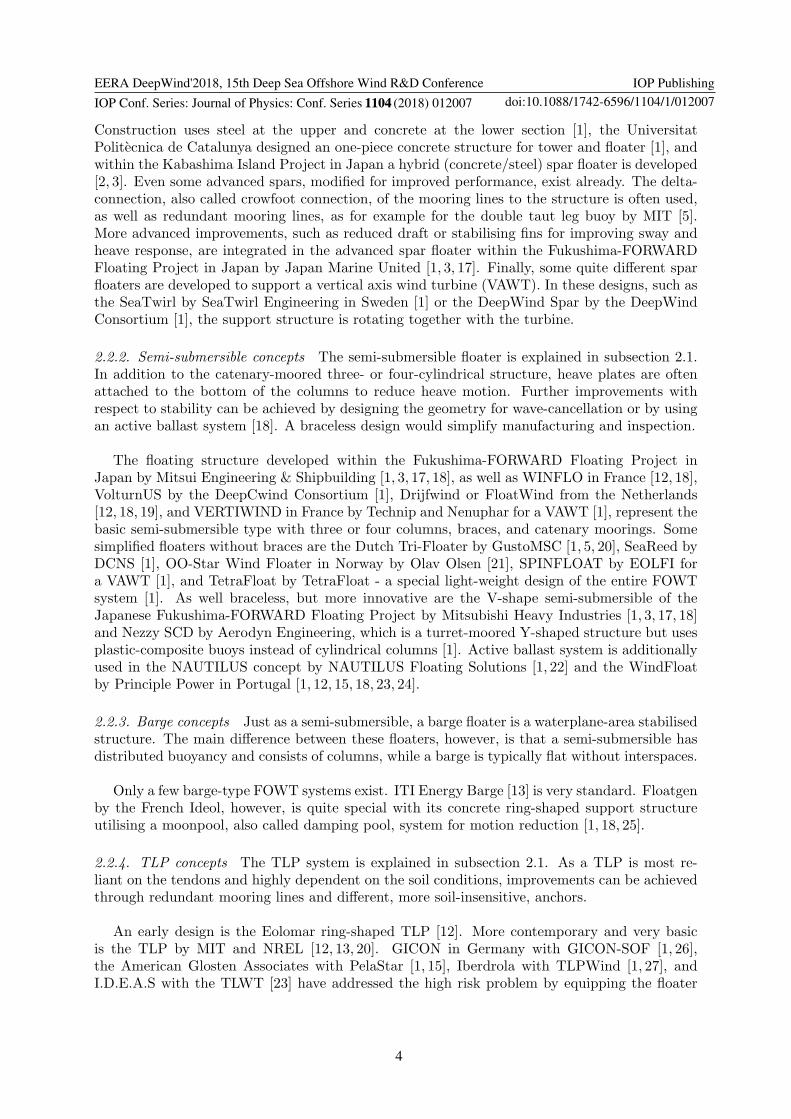
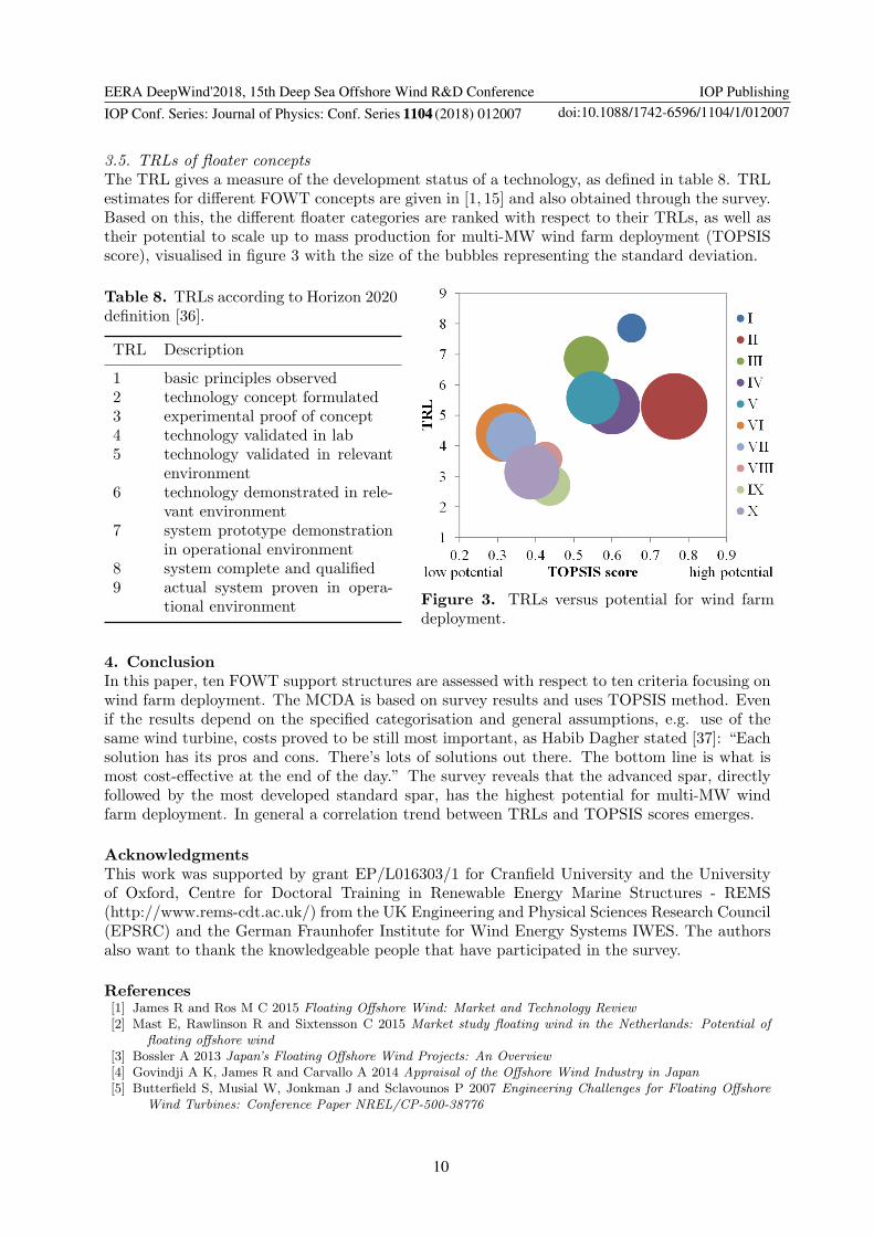
The TRL gives a measure of the development status of a technology, as defined in table 8. TRLestimates for different FOWT concepts are given in [1, 15] and also obtained through the survey.Based on this, the different floater categories are ranked with respect to their TRLs, as well astheir potential to scale up to mass production for multi-MW wind farm deployment (TOPSISscore), visualised in figure 3 with the size of the bubbles representing the standard deviation.
Table 8. TRLs according to Horizon 2020definition [36].
TRL Description
1 basic principles observed2 technology concept formulated3 experimental proof of concept4 technology validated in lab5 technology validated in relevant
environment6 technology demonstrated in rele-
vant environment7 system prototype demonstration
in operational environment8 system complete and qualified9 actual system proven in opera-
tional environment Figure 3. TRLs versus potential for wind farmdeployment.
4. Conclusion
In this paper, ten FOWT support structures are assessed with respect to ten criteria focusing onwind farm deployment. The MCDA is based on survey results and uses TOPSIS method. Evenif the results depend on the specified categorisation and general assumptions, e.g. use of thesame wind turbine, costs proved to be still most important, as Habib Dagher stated [37]: “Eachsolution has its pros and cons. There’s lots of solutions out there. The bottom line is what ismost cost-effective at the end of the day.” The survey reveals that the advanced spar, directlyfollowed by the most developed standard spar, has the highest potential for multi-MW windfarm deployment. In general a correlation trend between TRLs and TOPSIS scores emerges.
Acknowledgments
This work was supported by grant EP/L016303/1 for Cranfield University and the Universityof Oxford, Centre for Doctoral Training in Renewable Energy Marine Structures - REMS(http://www.rems-cdt.ac.uk/) from the UK Engineering and Physical Sciences Research Council(EPSRC) and the German Fraunhofer Institute for Wind Energy Systems IWES. The authorsalso want to thank the knowledgeable people that have participated in the survey.
References[1] James R and Ros M C 2015 Floating Offshore Wind: Market and Technology Review[2] Mast E, Rawlinson R and Sixtensson C 2015 Market study floating wind in the Netherlands: Potential of
floating offshore wind[3] Bossler A 2013 Japan’s Floating Offshore Wind Projects: An Overview[4] Govindji A K, James R and Carvallo A 2014 Appraisal of the Offshore Wind Industry in Japan[5] Butterfield S, Musial W, Jonkman J and Sclavounos P 2007 Engineering Challenges for Floating Offshore
Wind Turbines: Conference Paper NREL/CP-500-38776

EERA DeepWind'2018, 15th Deep Sea Offshore Wind R&D Conference
IOP Conf. Series: Journal of Physics: Conf. Series 1104 (2018) 012007
IOP Publishing
doi:10.1088/1742-6596/1104/1/012007
11
[6] Taboada J V 2015 Comparative Analysis Review on Floating Offshore Wind Foundations (FOWF)[7] Borg M and Collu M 2015 A comparison between the dynamics of horizontal and vertical axis offshore floating
wind turbines Philosophical transactions A 373
[8] Nilsson D and Westin A 2014 Floating wind power in Norway: Analysis of future opportunities and challenges[9] DNV GL 2017 Electrifying the future (https://www.dnvgl.com/, 2017-12-14)
[10] European Wind Energy Association 2013 Deep Water: The next step for offshore wind energy[11] Seymour R J (ed) 1992 Ocean energy recovery: The state of the art[12] Henderson A R and Witcher D 2010 Floating offshore wind energy – a review of the current status and an
assessment of the prospects Wind Engineering 34 1–16[13] Matha D 2009 Model Development and Loads Analysis of an Offshore Wind Turbine on a Tension Leg
Platform, with a Comparison to Other Floating Turbine Concepts[14] Rummelhoff I and Bull S 2015 Building the world’s first floating offshore wind farm (https://www.statoil.
com/, 2017-12-16)[15] ORE Catapult 2015 Floating wind: technology assessment (https://ore.catapult.org.uk/, 2017-12-17)[16] Cruz J and Atcheson M (eds) 2016 Floating Offshore Wind Energy: The Next Generation of Wind Energy[17] Fukushima Offshore Wind Consortium 2017 Fukushima Floating Offshore Wind Farm Demonstration Project
(http://www.fukushima-forward.jp/english/, 2017-12-16)[18] Liu Y, Li S, Yi Q and Chen D 2016 Developments in semi-submersible floating foundations supporting wind
turbines: A comprehensive review Renew Sustain Energy Rev 60 433–449[19] Bulder, van Hees, Henderson, Huijsmans, Pierik, Snijders, Wijnants and Wolf 2002 Studie naar haalbaarheid
van en randvoorwaarden voor drijvende offshore windturbines (http://www.offshorewindenergy.org/,2017-12-15)
[20] Musial W, Butterfield S and Boone A 2004 Feasibility of Floating Platform Systems for Wind Turbines[21] Landbø T 2017 OO-Star Wind Floater: An innovative and robust semi-submersible for offshore floating wind[22] NAUTILUS 2017 Product (http://www.nautilusfs.com/en/, 2017-12-16)[23] Myhr A, Bjerkseter C, Agotnes A and Nygaard T A 2014 Levelised cost of energy for offshore floating wind
turbines in a life cycle perspective Renew Energ 66 714–728[24] Principle Power 2015 WindFloat (http://www.principlepowerinc.com/, 2017-12-16)[25] IDEOL 2017 Ideol winning solutions for offshore wind (http://ideol-offshore.com/en, 2017-12-16)[26] GICON 2016 The GICON SOF (http://www.gicon-sof.de/en/sof1.html, 2017-12-16)[27] ORE Catapult 2016 Introducing TLPWIND UK (https://ore.catapult.org.uk/, 2017-12-16)[28] Blue H Engineering 2017 Technology (http://www.bluehengineering.com/, 2017-12-16)[29] Koundouri P, Giannouli A and Souliotis I 2017 Renewable and Alternative Energy pp 1581–1601[30] Kolios A, Rodriguez-Tsouroukdissian A and Salonitis K 2016 Multi-criteria decision analysis of offshore wind
turbines support structures under stochastic inputs Ships Offshore Struc 11 38–49[31] Kolios A, Collu M, Chahardehi A, Brennan F P and Patel M H 2010 A Multi-Criteria Decision Making
Method to Compare Available Support Structures for Offshore Wind Turbines[32] Zhang X, Sun L, Sun H, Guo Q and Bai X 2016 Floating offshore wind turbine reliability analysis based on
system grading and dynamic FTA J. Wind. Eng. Ind. Aerodyn. 154 21–33[33] Mone C, Hand M, Bolinger M, Rand J, Heimiller D and Ho J 2017 2015 Cost of Wind Energy Review:
Technical Report NREL/TP-6A20-66861[34] Kolios A, Mytilinou V, Lozano-Minguez E and Salonitis K 2016 A comparative study of multiple-criteria
decision-making methods under stochastic inputs Energies 9 566[35] Lozano-Minguez E, Kolios A J and Brennan F P 2011 Multi-criteria assessment of offshore wind turbine
support structures Renew Energ 36 2831–2837[36] European Commission 2013 Horizon 2020 - Work Programme 2014-2015: Part 19. General Annexes Revised
(https://ec.europa.eu/commission/index_en, 2017-12-17)[37] Kosowatz J 2015 Options Bring Challenges to Floating Platforms (https://www.asme.org/, 2017-12-14)