Leica M165 FC Leica M205 FA User Manual - pragolab.cz€¦ · Leica M-series User Manual 3...
152
Leica M165 FC Leica M205 FA User Manual
Transcript of Leica M165 FC Leica M205 FA User Manual - pragolab.cz€¦ · Leica M-series User Manual 3...

Leica M165 FCLeica M205 FAUser Manual

Leica M-series User Manual 2
General Instructions
Safety conceptBefore using your microscope for the first time, please read the "Safety concept" brochure included with your instrument. It contains addi-tional information about handling and care.
Use in clean rooms The Leica M series can be used in clean rooms without any problems.
CleaningDo not use any unsuitable cleaning agents, ρ
chemicals or techniques for cleaning.
Never use chemicals to clean colored ρ
surfaces or accessories with rubberized parts. This could damage the surfaces, and specimens could be contaminated by abraded particles.
In most cases, we can provide special solu- ρ
tions on request. Some products can be modified, and we can offer other accesso-ries for use in clean rooms.
Servicing Repairs may only be carried out by Leica ρ
Microsystems-trained service technicians. Only original Leica Microsystems spare parts may be used.
Responsibilities of person in charge of instrument
Ensure that the Leica stereomicroscope ρ
is operated, maintained and repaired by authorized and trained personnel only.
Leica M-series User Manual 3
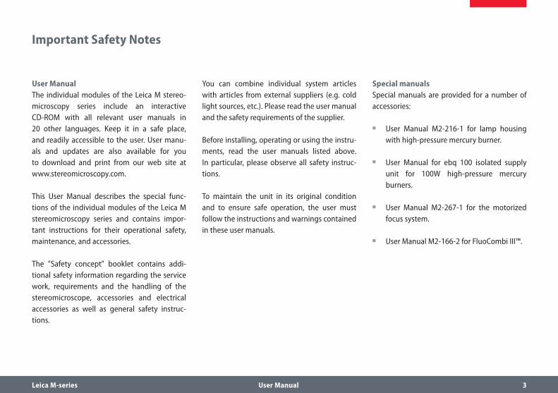
Important Safety Notes
User ManualThe individual modules of the Leica M stereo-microscopy series include an interactive CD-ROM with all relevant user manuals in 20 other languages. Keep it in a safe place, and readily accessible to the user. User manu-als and updates are also available for you to download and print from our web site at www.stereomicroscopy.com.
This User Manual describes the special func-tions of the individual modules of the Leica M stereomicroscopy series and contains impor-tant instructions for their operational safety, maintenance, and accessories.
The "Safety concept" booklet contains addi-tional safety information regarding the service work, requirements and the handling of the stereomicroscope, accessories and electrical accessories as well as general safety instruc-tions.
You can combine individual system articles with articles from external suppliers (e.g. cold light sources, etc.). Please read the user manual and the safety requirements of the supplier.
Before installing, operating or using the instru-ments, read the user manuals listed above. In particular, please observe all safety instruc-tions.
To maintain the unit in its original condition and to ensure safe operation, the user must follow the instructions and warnings contained in these user manuals.
Special manualsSpecial manuals are provided for a number of accessories:
User Manual M2-216-1 for lamp housing ρ
with high-pressure mercury burner.
User Manual for ebq 100 isolated supply ρ
unit for 100W high-pressure mercury burners.
User Manual M2-267-1 for the motorized ρ
focus system.
User Manual M2-166-2 for FluoCombi III™. ρ

Leica M-series User Manual 4
Symbols Used
Warning of a danger
• This symbol indicates especially impor-tant information that must be read and
complied with.
Failure to comply can cause the following:Hazards to personnel ρ
Functional disturbances or damaged instru- ρ
ments
Warning of hazardous electrical voltage
This symbol indicates especially impor-tant information that is mandatory to
read and observe.
Failure to comply can cause the following:Hazards to personnel ρ
Functional disturbances or damaged instru- ρ
ments
Danger due to hot surface
This symbol warns against touching accessible hot surfaces, e.g. those of
light bulbs.
Important information
This symbol indicates additional infor-mation or explanations that intend to
provide clarity.
Explanatory notesThis symbol within the text stands for addi- ρ
tional information and explanations.
Figures(1) Numbers in parentheses within the
descriptions relate to the figures and the items within those figures.

Leica M-series User Manual 5
Safety Instructions
DescriptionThe individual modules fulfill the highest requirements for observation and documenta-tion of Leica stereomicroscopes of the M series.
Intended useRefer to "Safety Concept" booklet
Non-intended useRefer to "Safety Concept" booklet
Never use M series microscopes or their compo-nents for surgical procedures (e.g. on the eye) unless they are specifically intended for that purpose.
The instruments and accessories described in this operating manual have been tested for safety and potential hazards. The responsible Leica affiliate must be consulted whenever the instrument is altered, modified or used in conjunction with non-Leica components that
are outside of the scope of this manual.
Unauthorized alterations to the instrument or noncompliant use shall void all rights to any warranty claims.
Place of useRefer to "Safety Concept" booklet
Electrical components must be placed at ρ
least 10 cm away from the wall and from flammable substances.
Avoid large temperature fluctuations, ρ
direct sunlight and vibrations. These condi-tions can distort measurements and micro-graphic images.
In warm and warm-damp climatic zones, ρ
the individual components require special care in order to prevent the build-up of fungus.
Responsibilities of person in charge of instrument
Refer to "Safety Concept" booklet
Ensure that:The M series stereomicroscopes and ρ
accessories are operated, maintained and repaired by authorized and trained person-nel only.
All operators have read, understood and ρ
observe this User Manual, and particularly the safety instructions.

Leica M-series User Manual 6
Safety Instructions (cont'd.)
Repairs, service workRefer to "Safety Concept" booklet
Only original Leica Microsystems spare ρ
parts may be used.
Before opening the instruments, switch off ρ
the power and unplug the power cable.
Touching the live circuit can cause injury.
TransportUse the original packaging for shipping or ρ
transporting the individual modules of the Leica M stereomicroscopy series and the accessory components.
In order to prevent damage from vibrations, ρ
disassemble all moving parts that (accord-ing to the user manual) can be assembled and disassembled by the customer and pack them separately.
Integration in third-party productsRefer to "Safety Concept" booklet
DisposalRefer to "Safety Concept" booklet
Legal requirementsRefer to "Safety Concept" booklet
EC Declaration of ConformityRefer to "Safety Concept" booklet ρ
Health risks
• Workplaces with stereomicroscopes facilitate and improve the viewing task,
but they also impose high demands on the eyes and holding muscles of the user. Depending on the duration of uninterrupted work, asthenopia and musculoskeletal problems may occur. For
this reason, appropriate measures for reduction of the workload must be taken:
Optimal arrangement of workplace, work ρ
assignments and work flow (changing tasks frequently).
Thorough training of the personnel, giving ρ
consideration to ergonomic and organiza-tional aspects.
The ergonomic design and construction ρ
of the Leica M stereomicroscopy series are intended to reduce the exertion of the user to a minimum.

Leica M-series User Manual 7
Safety Instructions (cont'd.)
• Direct contact with eyepieces is a poten-tial transmission method for bacterial
and viral infections of the eye.
The risk can be kept to a minimum by using personal eyepieces for each individual or detachable eyecups.
Light sources: Safety regulationsProtective measures of the manufacturer:
UV protection screen in front of the speci- ρ
men plane prevents the user from looking directly into the UV rays.
Dummy filter carriers in the free positions ρ
of the rapid filter changer prevent direct UV radiation from reaching the eyes.
UV filters are installed in the observation ρ
beam paths to protect the eyes.
The stray-light protection on the lamp ρ
housing prevents irradiation of the hands.
Warning
• UV radiation could damage the eyes. Therefore:
Never look into the light spot on the speci- ρ
men plane without a UV protection screen.
Never look into the eyepieces if no excita- ρ
tion filter is in the beam path.
Fill empty filter positions with dummy filter ρ
carriers (e.g. M165 FC).
Do not select a white, strongly reflective ρ
background for the specimen.

Leica M-series User Manual 8
Safety Instructions (cont'd.)
Supply unitAlways unplug the supply unit from the power supply:
When installing and disassembling the ρ
lamp housing
Before opening the lamp housing ρ
When replacing the high-pressure mercury ρ
lamp and other parts, such as the heat-absorbing filter or the collector
During maintenance work on the supply ρ
unit
Lamp housing
• Never open the lamp housing while the lamp is switched on. Risk of explosion,
UV exposure, blinding!
• Before opening the lamp housing, allow it to cool off for at least 15 minutes.
Danger of explosion!
• Never cover the air duct on the lamp housing. Danger of fire!
Mercury lampFollow the user manual and safety instruc- ρ
tions provided by the lamp manufacturer, and, in particular, the section on how to proceed if a lamp breaks and releases mercury.
For transport, remove the mercury lamp, ρ
transport it in its original packaging and protect moving parts in the lamp housing using the transport anchors.
When it has reached the end of its rated life ρ
(follow the manufacturer's specifications and the minute meter on the supply unit).
To minimize the risk of explosion, replace a ρ
discolored mercury lamp promptly.
Leica Microsystems assumes no liability ρ
for damage caused by exploding, incor-rectly installed or improperly used mercury lamps.

Leica M-series User Manual 9
Contents
General Instructions 2Important Safety Notes 3Symbols Used 4Safety Instructions 5
The Leica M Series for FluorescenceCongratulations! 13A Step Towards Infinity 14The Electronics: Comfort, Convenience and Safety 15The Modular Design: Everything is Relative 16Maximum Compatibility 17On We Go 18
AssemblyAssembling the Focusing Column for MDG Bases 20Assembling the Focusing Column with an Incident-light Base 21Motorized Focus: Restricting the Travel Path 22Optics Carrier 23Tube 24Eyepieces 25Objective 26UV Protection Screen – Assembly 27Objective Nosepiece – Assembly 28Objective Nosepiece – Adjusting Parfocality 29
Transmitted-light Base TL ST 30FluoCombi III™ – Preparations 31FluoCombi III™ – Assembly 32FluoCombi III™ – Adjusting the Parfocality 34FluoCombi III™ – Centering the Objectives 36FluoCombi III™ – Filter and UV Protection Screen 37Transmitted-light Base TL BFDF: Before First Use 38Transmitted-light Base TL BFDF 39TL RC™ / TL RCI™ 40IsoPro™ Manual Mechanical Stage: Assembly 41Leica IsoPro™ Motorized Mechanical Stage: Assembly 44Cables: Connections 48Cables: Cable Duct 49Cables: Diagram 50Leica LED5000 MCI™ 51Leica LED5000 MCI™: Alternative Assembly 52Leica LED5000 RL 53Leica EL6000 – Safety Notes 54Leica EL6000 – Preparations 57Leica EL6000 – Connection to the Fluorescence Lamp Housing 59Leica EL6000 – Replacing the Lamp 61Leica EL6000 – Connection to the Fluorescence Lamp Housing (cont'd.) 62

Leica M-series User Manual 10
Quick Start GuideThe Fastest Route to Success 64Overview of an M Series Microscope 65The Correct Interpupillary Distance 66Using the Eyepieces 67Focusing 68Adjusting the Resistance of the Focus Drive 69Changing Magnification (Zoom) 70Ratchet Steps and Magnification Levels 71Parfocality: More Comfort and Convenience for Your Work 72Iris Diaphragm 73
EyepiecesMagnification Factors of the Eyepieces 75Health Notes 76Dioptric Correction 77Dioptric Correction and Parfocality 78Graticules 79
Photography & VideoPhotography & Video 81Photo Tubes and C-mounts 82Trinocular Video/Phototube 50% 83Trinocular Video/Phototube 100% 84
Microscope CarrierThe Objective Nosepiece 86
Objectives andOptical AccessoriesThe Different Types of Objectives 88
BasesLeica TL ST Transmitted-light Base: Controls 90Leica TL ST Transmitted-light Base: Operation 91Leica TL ST Transmitted-light Base: Changing Bulbs 92Leica TL BFDF Transmitted-light Base: Controls 93Leica TL BFDF Transmitted-light Base: Operation 94Leica TL RC™ / TL RCI™: Controls 95Leica TL RCI™: The Deflection Mirror 96Leica TL RCI™: Color Intensity and Temperature 97Leica TL RC™ / TL RCI™: Operation 98Leica TL RCI™: Methods in Transmitted Light 99Leica TL RCI™: Relief Images 100Using Filters 102Leica IsoPro™ (Non-motorized): Controls 103Leica IsoPro™ (Motorized): Controls 104

Leica M-series User Manual 11
System IlluminationLeica LED5000 MCI™ 106Leica LED5000 RL 108Leica EL6000 – About the Instrument 109Leica EL 6000 – Operation 111Leica EL 6000 – Troubleshooting 112Cleaning and Maintenance 113
FluorescenceFilter Changer 115FIM – Fluorescence Intensity Manager 116About Fluorescence Microscopy 117Rapid Filter Changers and Filter Types 118Simple filter holders 119Equipping the Filter Changer 120Observation without Fluorescence 121Double Iris Aperture 122Commissioning the Fluorescence System 123
AccessoriesLeica SmartMove 125Leica SmartTouch™ 126Leica PSC Controller 127
Dimensional DrawingsLeica M165 FC 129Leica M205 FA 132Leica LED5000 MCI 135Leica LED5000 RL 136MATS TL 137
SpecificationsLeica M165 FC / Leica M205 FA 139Leica EL6000 – Specifications 143Leica TL ST Transmitted-light Base 145Leica TL BFDF Transmitted-light Base 146Leica TL RC™ / TL RCI™ 147Leica IsoPro™ Motorized XY Stage 148
AppendixCalculating the Total Magnification and Field of View Diameter 150Care, Maintenance, Contact Persons 151

Leica M-series User Manual 12
The Leica M Series for Fluorescence

Leica M-series User Manual 13
Congratulations!
Congratulations on obtaining your new Leica M series stereomicroscope. We are convinced it will exceed your expectations, as never before have we applied our decades of experience in the areas of optics, mechanical engineering and ergonomics in such an uncompromising manner.
The Leica M series embodies all the qualities you associate with the name Leica Microsystems: excellent objectives, high-quality engineering, and reliability. Furthermore, the modular design ensures that the M series adapts perfectly to your needs—no matter which accessories you require for your tasks.
The entire imaging system, including the zoom, objective and ErgoTube®, is apochromatically corrected with much technological effort. Contrast, sharpness, richness in detail, resolution, image and color fidelity are opti-mum. In addition, the patented illumination beam path guarantees at every zoom level that light utilization is at a maximum and that fluorescence images are intensely luminous on a jet black background.
Though the reliability and robustness of Leica stereomicroscopes is legendary, like any high-tech product, the Leica M series requires a certain degree of care and attention. Therefore, we recommend that you read this manual. It contains all the information you need regarding operation, safety and maintenance. Simply observing a few guidelines will ensure that even after years of intensive use, your stereomicroscope will continue to work as smoothly and reliably as on the very first day.
We wish you the best of success in your work—after all, you are now equipped with the best tool!

Leica M-series User Manual 14
A Step Towards Infinity
Ever since their introduction by Horatio S. Greenough, stereomicroscopes have worked according to the optical principles based primarily on Ernst Abbe's research. For over a century, ingenious optics designers and engi-neers have worked to push magnification, reso-lution and image fidelity to the limit permitted by optics.
In doing so, they have always been constrained by the interrelation between three factors: the higher a microscope's resolution, the lower the available working distance. If one increases the distance of the optical axes, the three-dimen-sional image seen by the observer becomes distorted—a sphere becomes an ellipse, a flat surface curves towards the observer.
Limits are made to be brokenThe Leica M205 FA is the world's first fluores-cence stereomicroscope with a zoom range of 20.5:1. This accomplishment, however, was not enough for Leica's engineers. With the new FusionOptic™ in the Leica M205 FA, they have succeeded in going yet another step beyond previous limits. In addition to the increase in magnification, the resolution, too, has been increased to up to 1050 lp / mm, which corre-sponds to a resolved structure size of 472 nm.
Of course, this increase in performance benefits your everyday work. Set up your specimens on the microscope table with comfortable freedom of movement and discover details in stereomi-croscopy that you could never see before.
* Leica M205 FA with 1.0× planapochromat and 10× eyepieces

Leica M-series User Manual 15
The Electronics: Comfort, Convenience and Safety for Your Experiments
Never before have electronics been used as extensively in a Leica series as in the new M series lineup. Optics carrier, stand, base and illuminator are all connected using electrical contacts—which provides a number of advan-tages.
Reliability for your experimentsExact reproducibility of results is an increas-ingly common demand, particularly in research and development. The continuous encoding captures parameters such as the magnifica-tion, the illumination, the position of the iris
diaphragm and more and transmits the infor-mation to the Leica LAS software. Thus you always know the conditions under which an image was acquired.
Fewer cablesA large part of the cables have been routed in the interior of the column. Data are also trans-ferred via the interface between the column, the optics carrier and the carrier. The direct result is that you need fewer cables—this not only makes your workstation neater and more comfortable, it even makes it appear larger.
Contacts not only transmit data, but also supply the power.
Leica Application Suite (LAS) evaluates the transmitted data and can restore the test situa-tion later.

Leica M-series User Manual 16
Have a special request? Let us know!Leica Microsystems enjoys an exceptional repu-tation when it comes to devising customer-specific solutions. If you have a special request that cannot be met with standard parts, contact your Leica consultant. We have a solution for every problem.
The Modular Design: Everything is Relative
The Leica M series provides maximum flexibil-ity in choosing equipment, thanks primarily to the modular configuration and the compatibil-ity that Leica has painstakingly maintained for decades. The optics carriers, eyepieces, bases and more can be combined in any way you choose, allowing you to create the microscope that best suits your needs.
Despite this, you will notice that the controls and individual components do not differ signif-icantly. Whichever configuration you choose, you will quickly feel right at home.
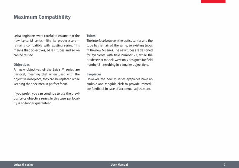
Leica M-series User Manual 17
Leica engineers were careful to ensure that the new Leica M series—like its predecessors—remains compatible with existing series. This means that objectives, bases, tubes and so on can be reused.
ObjectivesAll new objectives of the Leica M series are parfocal, meaning that when used with the objective nosepiece, they can be replaced while keeping the specimen in perfect focus.
If you prefer, you can continue to use the previ-ous Leica objective series. In this case, parfocal-ity is no longer guaranteed.
TubesThe interface between the optics carrier and the tube has remained the same, so existing tubes fit the new M series. The new tubes are designed for eyepieces with field number 23, while the predecessor models were only designed for field number 21, resulting in a smaller object field.
EyepiecesHowever, the new M-series eyepieces have an audible and tangible click to provide immedi-ate feedback in case of accidental adjustment.
Maximum Compatibility

Leica M-series User Manual 18
On We Go
If your new Leica microscope has already been assembled and commissioned by your Leica consultant, click here to skip through the instal-lation instructions and go directly to the Quick Start Guide on Page 63.
If, on the other hand, you are assembling the microscope yourself, continue with the "Assembly" chapter, which begins on Page 19.
For everything you need to know about the correct use of fluorescence-related parts, refer to Page 114.

Leica M-series User Manual 19
Assembly

Leica M-series User Manual 20
The first step is to connect the focusing column of the M series to the corresponding base.
Tools usedHex socket screwdriver, 3 mm ρ
Assembling the column adapter1. Securely install the column adapter on the
column using the four included screws.
Assembling the focusing column2. Securely screw the focusing column to the
base using the six included screws.
Assembling the Focusing Column for MDG Bases

Leica M-series User Manual 21
Assembling the Focusing Column with an Incident-light Base
When using an incident-light base, the focus-ing column and motorized focus are installed directly on the base; no extension plate is required.
Tools usedHex socket screwdriver, 3 mm ρ
Assembly1. Place the focusing column on the side.
2. Insert the four screws provided into the outer holes of the base.
3. Screw the base securely onto the focusing drive.

Leica M-series User Manual 22
Depending on the work situation, it is useful to restrict the maximum travel
path of the stereomicroscope. This prevents injury during handling of the sample caused by fingers or hands becoming trapped or the specimen touching the objective or even being damaged by it.
Readjusting the motorized focusThe motorized focus is factory-adjusted and normally does not need to be readjusted—even if the maximum travel path is changed.
• Exception: If the power fails while the motorized focus is moving, the position
data are lost. In this case, the calibration must be repeated using the Leica LAS software or the Leica SmartTouch™. To do so, please consult the respective manual.
Restricting the bottom travel range1. Move the motorized focus into the lowest
position you want to reach.
2. Unscrew the screw of the limit stop on the side of the focusing column.
3. Push the limit stop to the height of the motorized focus.
It is easiest to move the limit stop by keeping the screwdriver inserted and moving it upwards.
4. Tighten the screw of the limit stop.
Motorized Focus: Restricting the Travel Path

Leica M-series User Manual 23
Tools usedHex socket screwdriver, 4 mm ρ
Assembling the optics carrier1. Place the optics carrier on the focusing
column so that the screw fits into the thread provided and the lug fits into the groove.
2. Press the optics carrier backwards to the focusing column and screw it in place using your other hand.
Optics Carrier

Leica M-series User Manual 24
Tube
All intermediate tubes that fit between the optics carrier and the binocular tube are fitted in the same manner.
Tools usedNo tools required. ρ
Preparations1. Unscrew the positioning screw and remove
the protective cover.
Assembling the tube2. Push the tube (for example, the inclined
binocular tube) into the dovetail ring and rotate it slightly in both directions until the positioning screw meshes with the guide groove.
3. While holding the tube only slightly, care-fully tighten the positioning screw. It is automatically brought to the correct posi-tion.

Leica M-series User Manual 25
Eyepieces
Tools usedNo tools required. ρ
Magnification rangeYou can extend the overall magnification range using available 10×, 16×, 25× and 40× wide-field eyepieces for persons wearing glasses.
Preparation1. If you want to use an optional graticule,
insert it now (Page 79).
2. Remove the plastic tube guard.
Inserting the eyepieces3. Push the eyepieces into the tubes as far as
they will go and check to ensure that they fit tightly and accurately.
4. Securely tighten the clamping screws.

Leica M-series User Manual 26
Objective
Tools usedNo tools required. ρ
Preparation1. Remove the protective cap on the optics
carrier by turning it.
Attaching the objective
• Hold the objective firmly during assem-bly and disassembly so that it does not
fall onto the stage plate. This applies particu-larly to the 2x planapochromatic objective, which is very heavy. Remove all specimens from the stage plate first.
2. Screw the objective clockwise into the optics carrier.
Alternative fastening optionsIf using the objective nosepiece, read the ρ
instructions on Page 28.
If using the Leica FluoCombi III™, read the ρ
instructions on Page 31.

Leica M-series User Manual 27
UV Protection Screen: Assembly
Tools usedAllen key ρ
Intended useThe UV protection screen in front of the speci-men plane prevents the user from looking directly into the UV rays.
Safety Notes
• UV radiation can damage the eyes. Therefore, it is mandatory to install the
UV filter and adjust it correctly.
• Always position the UV protection screen so that the operator can never
look directly at the light spot.
Use with one objective1. Adjust the UV protection screen laterally
using the arm.
2. Unscrew the hexagon-head screw.
3. Adjust the UV protection screen using the arm.
4. Tighten the hexagon-head screw.
5. Fasten the UV protection screen using a hexagon-head screw to the left or right side of the microscope carrier.

Leica M-series User Manual 28
Preparations
• Hold the objectives firmly during assembly and disassembly so that they
do not fall onto the stage plate.
Move the drive housing all the way upwards ρ
and remove the optics carrier, if the carrier has already been installed.
Assembly1. Remove the transport anchor from the
objective nosepiece.
2. Rotate the moving part by 90° and attach the objective nosepiece to the drive hous-ing from the front (!). Screw the objective nosepiece firmly into place.
3. Unscrew the three Phillips screws on the objective mount of the optics carrier and remove the intermediate ring.
4. Screw the optics carrier onto the objective nosepiece.
5. Screw both objectives onto the objective nosepiece. It makes no difference which position an objective occupies.
6. Unscrew the locking screws on both sides of the objective nosepiece.
You can now adjust the parfocality (see instruc-tions on the next page).
Objective Nosepiece – Assembly

Leica M-series User Manual 29
Objective Nosepiece – Adjusting Parfocality
The following procedure only has to be carried out once. Afterwards, both objectives are parfo-cal, meaning that the specimen remains in focus when the objective nosepiece is rotated.
This procedure must be repeated if you replace either of the two objectives with another.
The following example assumes the combi-nation of the 1× and 2× planapochromats. If you are using another objective combination, replace the 2× objective in the description with the objective with the stronger magnification.
PreparationOpen the iris diaphragm. ρ
Set the dioptric correction of the eyepieces ρ
to "0".
Adjustment1. Rotate the 2× objective into the beam path
and set it to the lowest magnification.
2. Focus on the specimen.
3. Rotate the 1× objective into the beam path.
4. Turn the objective on the thread in both directions until the specimen appears sharp.
5. Toggle to the 2× objective.
6. Select the strongest magnification and refocus until the specimen appears abso-lutely sharp.
7. Toggle to the 1× objective.
8. Turn the objective on the thread in both directions until the specimen appears absolutely sharp.
By means of zooming, check that the behavior of the objective is parfocal. Repeat the check with the other objective. If it is not parfocal, repeat the procedure.
9. Tighten the locking screws.

Leica M-series User Manual 30
Transmitted-light Base TL ST
Unpacking the baseThe base is delivered with the adapter plate installed. Make sure the instruments are unpacked on a flat, sufficiently dimensioned, and non-slip surface.
Focusing drive and column1. Unscrew the extension plate from the base
using the Allen key provided.
2. Attach your focusing drive column from below using the four hexagon-head screws.
3. Re-attach the adapter plate to its origi-nal position using the six hexagon-head screws.

Leica M-series User Manual 31
FluoCombi III™ – Preparations
Before assembling the FluoCombi™, you have to disconnect all instruments
from the power supply. Failure to observe these instructions can result in damage to the micro-scope and the connected instruments.
Preparations1. Remove the two screws used as transport
anchors.
2. Screw the two screws into the holes provided for storage.
In this way, you can secure the FluoCombi III™ for transport whenever necessary.
3. Screw the 5× planapochromat into the FluoCombi III™.
4. Screw the other planapochromatic stereo objective into the FluoCombi III™.

Leica M-series User Manual 32
FluoCombi III™ – Assembly
1. Guide the FluoCombi III™ in from below, while holding it flat. Ensure that it is aligned with the holder on the focusing column at the left and right.
2. Hold the FluoCombi III™ securely and screw it to the focusing column using the provided screw.

Leica M-series User Manual 33
Assembling the optics carrier1. Unscrew the three screws and the adapter
ring on the optics carrier.
2. Attach the optics carrier to the FluoCombi III and screw it into place.
3. Open the iris diaphragm completely.
4. Assemble the tube (see Page 24).
5. Assemble the illuminator (see Page 51 ff.)
FluoCombi III™ – Assembly (cont'd.)

Leica M-series User Manual 34
FluoCombi III™ – Adjusting the Parfocality
Setting up the objective nosepiece
The following configuration only has to be carried out once. It ensures that the
parfocality remains intact, and thus the speci-men does not need to be brought into focus again.
1. Place a specimen under the microscope.
2. Rotate the stereo planachromatic objective under the beam path.
3. Reduce the view so that you can see the specimen in the overview.
4. Center the specimen under the beam path.
5. Adjust the magnification to the highest level and focus on a flat specimen.
6. Rotate the 5× planachromat under the beam path.
7. Unscrew the clamping screw on the objective.
8. Reduce the view so that you can see the specimen in the overview.

Leica M-series User Manual 35
FluoCombi III™ – Adjusting the Parfocality (cont'd.)
9. By turning the objective ring, focus on the specimen until the specimen appears abso-lutely sharp.
10. Enlarge the view just enough for the center of the specimen to be visible in the field of view.
11. Refocus.
12. Tighten the clamping screw (see Step 7).
13. Rotate the stereo planachromatic objective under the beam path.
This causes the two objectives to be parfo-cal. This means that from then on, you can toggle between the two objectives without refocusing.

Leica M-series User Manual 36
4. Center the objective over the specimen by loosening or tightening the screw on one side of the objective holder while turning the screw on the other side in the opposite direction.
FluoCombi III™ – Centering the Objectives
The following configuration only has to be carried out once. It ensures that the
specimen remains in the optical center when the objective is changed.
To attain optimum results for the follow-ing settings, insert a graticule into the
eyepiece. This makes locating the center vastly easier.
Centering the objective1. Rotate the 5× planachromat under the
beam path.
2. Focus on the midpoint of the specimen.
3. Rotate the stereo planachromatic objective under the beam path.

Leica M-series User Manual 37
FluoCombi III™ – Filter and UV Protection Screen
Inserting the dichroic mirror1. Pull the dummy filter carrier out of the
holder.
2. Insert the corresponding dichroic mirror.
Assembling the UV protection screen1. Screw the UV protection screen to the
holder provided on the optics carrier.
2. Orient the UV protection screen so that you cannot look directly into the UV light.

Leica M-series User Manual 38
Removing the transport anchors
• Before you can use the transmitted-light base for the first time, it is abso-
lutely necessary to remove the two transport anchors.
Transmitted-light Base TL BFDF: Before First Use
Anchor of switching slide
Anchor of mirror
Leica M-series User Manual 39
Transmitted-light Base TL BFDF
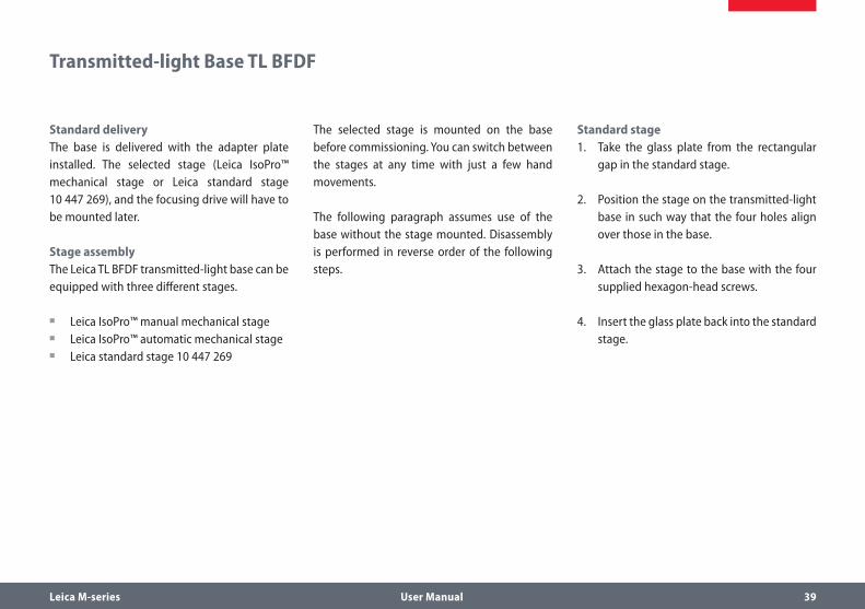
Standard deliveryThe base is delivered with the adapter plate installed. The selected stage (Leica IsoPro™ mechanical stage or Leica standard stage 10 447 269), and the focusing drive will have to be mounted later.
Stage assemblyThe Leica TL BFDF transmitted-light base can be equipped with three different stages.
Leica IsoPro™ manual mechanical stage ρ
Leica IsoPro™ automatic mechanical stage ρ
Leica standard stage 10 447 269 ρ
The selected stage is mounted on the base before commissioning. You can switch between the stages at any time with just a few hand movements.
The following paragraph assumes use of the base without the stage mounted. Disassembly is performed in reverse order of the following steps.
Standard stage1. Take the glass plate from the rectangular
gap in the standard stage.
2. Position the stage on the transmitted-light base in such way that the four holes align over those in the base.
3. Attach the stage to the base with the four supplied hexagon-head screws.
4. Insert the glass plate back into the standard stage.

Leica M-series User Manual 40
The base is delivered with the adapter plate installed. The selected stage (Leica IsoPro™ mechanical stage or Leica standard stage 10 447 269), and the focusing drive will have to be mounted later.
Ensure that the instruments are unpacked on a level, adequately sized, and nonskid underlay.
Stage assemblyThe Leica TL RC™/ RCI™ transmitted-light base can be equipped with three different Leica stages. The selected stage is mounted on the base before commissioning. You can switch between the stages at any time with just a few hand movements.
The following paragraph assumes use of the base without the stage mounted. Disassembly is performed in reverse order of the following steps.
Standard stage1. Take the glass plate from the rectangular
gap in the standard stage.
2. Position the stage on the transmitted-light base in such way that the four holes align over those in the base.
3. Attach the stage to the base with the four supplied hexagon-head screws.
4. Insert the glass plate back into the standard stage.
TL RC™ / TL RCI™

Leica M-series User Manual 41
IsoPro™ Manual Mechanical Stage: Assembly
Before the Leica IsoPro™ mechanical stage is mounted to the base, the axis containing the control buttons is attached either on the left or the right side of the mechanical stage.
Leica IsoPro™ Mechanical StageBefore the Leica IsoPro™ mechanical stage is mounted to the base, the axis containing the control buttons is attached either on the left or the right side of the mechanical stage.
If the controls are to be mounted on the left-hand side, the gear rod on the bottom side of the mechanical stage must be unscrewed and reattached in reverse.
1. Take the glass plate from the mechanical stage.
2. Turn the mechanical stage around and place it onto a non-slip surface.
3. Change the gear rod from the left to the right-hand side.
4. Skip the next two steps to install the controls.
Left or right operationIf the controls are to be mounted on the left-hand side, the gear rod on the bottom side of the mechanical stage must be unscrewed and reattached in reverse.

Leica M-series User Manual 42
Leica IsoPro™ Manual Mechanical Stage: Assembly (cont'd.)
1. Take the glass plate from the mechanical stage and turn it around.
2. Change the gear rod from the left to the right-hand side.
Control assembly1. Take the glass plate from the mechanical
stage and turn it around.
2. Attach the axis with the control buttons to the desired side. The fastener snaps into the mechanical stage magnetically.
4. Attach the axis with the two supplied hexa-gon-head screws.
5. Attach the cover rail to the mechanical stage.
Mechanical stage assembly1. Place the mechanical stage onto the base.
2. Pull the upper part of the mechanical stage carefully towards the user, fixing the lower part onto the transmitted-light base.
Leica M-series User Manual 43
Leica IsoPro™ Manual Mechanical Stage: Assembly (cont'd.)
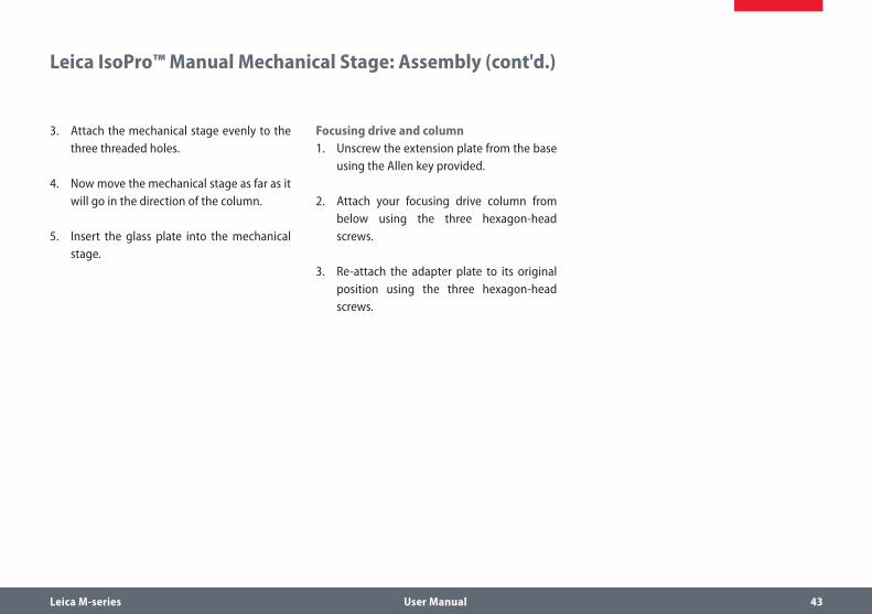
3. Attach the mechanical stage evenly to the three threaded holes.
4. Now move the mechanical stage as far as it will go in the direction of the column.
5. Insert the glass plate into the mechanical stage.
Focusing drive and column1. Unscrew the extension plate from the base
using the Allen key provided.
2. Attach your focusing drive column from below using the three hexagon-head screws.
3. Re-attach the adapter plate to its original position using the three hexagon-head screws.

Leica M-series User Manual 44
BasicsThe transmitted light bases of the Leica TL series (TL BFDF, TL RC™, TL RCI™) are supplied with an installed extension plate. The selected stage (Leica IsoPro™ mechanical stage or standard stage 10 447 269) and the focusing drive will have to be mounted later.
The motorized mechanical stage is a sensi-tive precision instrument. During installation, avoid subjecting the stage to impact or severe vibrations.
1. Unpack the mechanical stage from the transport packaging and position it on the transmitted-light base.
2. Secure the motorized mechanical stage to the base using three M4 screws.
Leica IsoPro™ Motorized Mechanical Stage: Assembly
3× M4 screws
1
2
1 Microscope base2 Motorized mechanical stage

Leica M-series User Manual 45
3. Remove the two M3 screws and the holder from the mechanical stage.
4. Remove the two M4 screws and the sleeve from the mechanical stage.
5. Remove the four shock-absorbing cartons from the mechanical stage.
After removal, keep all the transport anchors in the plastic bag provided for
future transport.
Leica IsoPro™ Motorized Mechanical Stage: Assembly (cont'd.)

Leica M-series User Manual 46
Leica IsoPro™ Motorized Mechanical Stage: Assembly (cont'd.)
The basesThe TL BFDF, TL RC™ and RCI™ transmitted-light bases can be equipped with three different stages: Standard stage, manual and automated IsoPro™ mechanical stage. The selected stage is mounted on the base before commissioning. You can switch between the stages at any time with just a few hand movements.
The following paragraph assumes use of the base without the stage mounted. Disassembly is performed in reverse order of the following steps.
Mechanical stage and base
• Never move the sledge of the motor-ized mechanical stage manually in the
X direction, as otherwise the mechanical system will be damaged!
1. Place the mechanical stage onto the base.
2. Pull the upper part of the mechanical stage carefully towards the user and fasten the lower part onto the transmitted-light base.
3. Attach the mechanical stage evenly to the three threaded holes.
4. Now move the mechanical stage as far as it will go in the direction of the column.
5. Insert the glass plate into the mechanical stage.
Leica M-series User Manual 47
Leica IsoPro™ Motorized Mechanical Stage: Assembly (cont'd.)
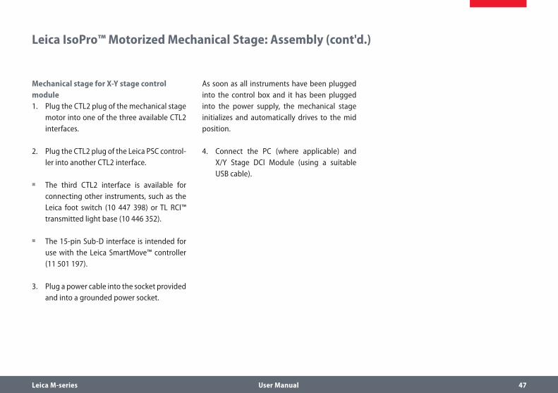
Mechanical stage for X-Y stage control module1. Plug the CTL2 plug of the mechanical stage
motor into one of the three available CTL2 interfaces.
2. Plug the CTL2 plug of the Leica PSC control-ler into another CTL2 interface.
The third CTL2 interface is available for ρ
connecting other instruments, such as the Leica foot switch (10 447 398) or TL RCI™ transmitted light base (10 446 352).
The 15-pin Sub-D interface is intended for ρ
use with the Leica SmartMove™ controller (11 501 197).
3. Plug a power cable into the socket provided and into a grounded power socket.
As soon as all instruments have been plugged into the control box and it has been plugged into the power supply, the mechanical stage initializes and automatically drives to the mid position.
4. Connect the PC (where applicable) and X/Y Stage DCI Module (using a suitable USB cable).

Leica M-series User Manual 48
The new Leica M-series features extensive encoding with which various microscope data and settings can be read out, transferred to the PC and reproduced later.
The interface to the optics carrier is on the ρ
column.
The terminals The connection to the PC and to other instru-ments is made using the terminals on the rear side of the column:
1. 2 CTL2 terminals for auxiliary equipment such as the ring illuminator, the base and other accessories from the Leica product range.
2. Terminal for the 50-watt power supply provided.
3. USB terminal for the connection to the PC.
Cables: Connections
1
2
3

Leica M-series User Manual 49
The integrated cable duct in the column enables a neat cable layout around the microscope. For example, the USB or FireWire cables of the camera can be stowed in the cable duct.
Feeding the cables1. Unscrew the three screws on the cable
duct.
2. Remove the cover of the cable duct.
3. Place the cables in the cable duct and screw the cover on tightly.
Tip: Estimate the length of the cable ends you will need before screwing on the cover. For thick cables, it is difficult to change the length retroactively.
Cables: Cable Duct

Leica M-series User Manual 50
Cables: Diagram
TL RCI™
DCI Controlbox
PSC SmartTouch
PC USB
Cross StageSmart Move
Power/USB
LED5000 RL LED5000 MCI™
Footswitch(es)
Please use the Leica Application Suite to configure the functions of the system.
Alternative installation
115/230 V

Leica M-series User Manual 51
The Leica LED5000 MCI™ (for "Multi Contrast Illumination") is installed using two screws. For optimum accessibility, the optics carrier should be removed during assembly (see Page 23.)
ConstraintsThe Leica LED5000 MCI™ cannot be used together with the objective nosepiece.
Assembly
• 1. Hold the LED5000 MCI™ with one hand and tightly screw the retain-
ing stirrups on both top holes on the drive housing.
2. Connect the CAN-bus cable provided to either of the two sockets. (The flat part of the plug must be facing downwards.)
3. Plug the other end of the cable into one of the two "CTL2" sockets on the column.
Leica LED5000 MCI™

Leica M-series User Manual 52
Under certain circumstances, the light source must not be moved along with the optics carrier. A typical example is multifocus images in which the Z-stack changes while the angle of incidence of the light must remain the same. For such purposes, the Leica LED5000 MCI™ is directly fastened to the column.
Installation on the column1. Pull the retaining stirrup out of the Leica
LED5000 MCI™.
2. Screw the retaining stirrup into the column at the notch using the single screw. If you tighten the screw, the retaining stirrup is automatically moved into the correct position.
3. Push the Leica LED5000 MCI™ onto the retaining stirrup.
Leica LED5000 MCI™: Alternative Assembly

Leica M-series User Manual 53
The ring illuminator, the Leica LED5000 RL ("Ring Light"), is installed on the objective using a single screw. It has been optimized for a work-ing distance between 60 and 70 mm.
ConstraintsThe Leica LED5000 RL can be used in conjunc-tion with the planapochromat 1× and planapo-chromat 0.63× objectives. With all other objectives, the working distance is too low for adequate illumination.
The ring illuminator cannot be used together with the objective nosepiece.
Assembly1. Connect the CAN-bus cable to the ring illu-
minator. The flat part of the plug must be facing upwards.
2. Push the ring illuminator over the objective as far as it will go and screw it into place.
3. Plug the other end of the cable into one of the two "CTL2" sockets on the column.
For optimum accessibility of the specimen, the ring illuminator should be installed with the cable facing backwards. However, it is also possible to turn the ring illuminator side-ways, for example if simultaneously using the Leica LED5000 MCI™ system illumination. In this case, the ring illuminator cannot be connected directly to the Leica LED5000 MCI™.
Leica LED5000 RL

Leica M-series User Manual 54
• The manufacturer assumes no respon-sibility or liability for any use outside of
the intended use or use outside of the specifica-tions from Leica Microsystems Wetzlar GmbH or any risks resulting from such use.
In such cases, the Declaration of Conformity shall be invalid.
• This (IVD) device is not intended for use in the patient environment defined by
DIN VDE 0100-710. It is also not intended to be combined with medical devices as defined by EN 60601-1. If a microscope is electrically connected to a medical instrument in accor-dance with EN 60601-1, the requirements defined in EN 60601-1-1 shall apply.
General safety notesThis safety class 1 device was built and tested in accordance with EN 61010-2-101:2002EN 61010-1:2001,IEC 1010-1:2001, Safety requirements for electrical equipment for measurement, control and laboratory use.
The devices and accessories described in this operating manual have been tested for safety and potential hazards.
The responsible Leica affiliate or the main plant in Wetzlar must be consulted whenever the device is altered, modified or used in conjunc-tion with non-Leica components that are outside of the scope of this manual.
• Unauthorized alterations to the instru-ment or noncompliant use shall void all
rights to any warranty claims.
• If any safety defects or malfunctions of the Leica EL6000 are identified, the
instrument must be immediately disconnected from the power system and secured against additional use. For repair, the Leica EL6000 must be sent to the supplier or an authorized representative of the supplier.
Leica EL6000 – Safety Notes

Leica M-series User Manual 55
Leica EL6000 – Safety Notes (cont'd.)
• The Leica EL6000 compact light source generates high-energy light with invisi-
ble components. There is a risk of being dazzled or blinded by light! Never look directly into the light guide output of the instrument or into the output of the light guide connected to the instrument. Always ensure that the output of the connected light guide is securely connected to the system to be illuminated before switch-ing on the compact light source. Furthermore, before switching on the compact light source, dim the light output all the way using the intensity switch (left limit stop of the switch) to prevent damage to the connected system.
• To prevent damage to the light guide connected to the device, the heat-
absorbing filter inserted into the device must be free of damage (gaps, cracks etc.). If the heat-absorbing filter is not inserted or is defec-tive, the service life of the light guide will be decreased.
• The interior of the lamp inserted into the unit contains highly toxic substances.
At the end of its service life, dispose of the lamp according to applicable regulations. The manu-facturer of the lamp provides corresponding information, for example in the lamp's shipping documents. Follow the manufacturer's instruc-tions in case the lamp bursts.
• The Leica EL6000 compact light source is designed for a voltage range of
100 – 240 VAC, 50 – 60 Hz. Within this voltage and frequency range, the instrument always adapts to the connected power supply. Operat-ing the instrument with a power supply voltage outside this range can destroy the instrument and the connected components!
• Only fuses of the specified type and the listed rated current may be used as
replacements. The use of incorrect fuses may result in a fire hazard.
• The instrument is intended exclusively for operation in dry rooms. Do not
use the instrument in rooms with explosion hazard.
Leica M-series User Manual 56
Leica EL6000 – Safety Notes (cont'd.)
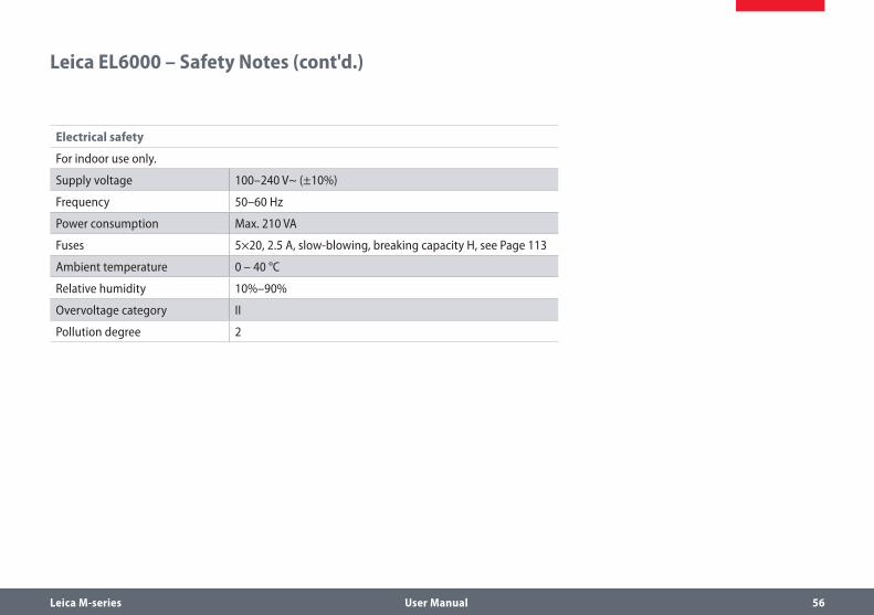
Electrical safety
For indoor use only.
Supply voltage 100–240 V~ (±10%)
Frequency 50–60 Hz
Power consumption Max. 210 VA
Fuses 5×20, 2.5 A, slow-blowing, breaking capacity H, see Page 113
Ambient temperature 0 – 40 °C
Relative humidity 10%–90%
Overvoltage category II
Pollution degree 2
Leica M-series User Manual 57
Setting up the instrument
• Set up the Leica EL6000 so that the front is readily accessible and visible.
The ventilation slots on the sides and back ρ
panel of the device must not be covered.
Maintain a free room of at least 150 mm on ρ
the rear panel of the instrument.
Instructions for lamp replacement
• The lamp contains mercury! Be abso-lutely certain to follow the handling
instructions and safety notes provided with the lamp.
• Maintain cleanliness when inserting the lamp. Remove any clinging packaging
materials.
• The lamp used in the instrument becomes very hot during operation and
has high internal pressure when hot. Before changing the lamp, it is mandatory to allow the instrument to cool off for at least 20 minutes.
• The Leica EL6000 compact light source comes with a factory-supplied lamp,
but the lamp is not installed when shipped. This minimizes the danger of damage to the lamp during transport.
• Before transporting the Leica EL6000 compact light source, you first have to
remove the lamp.
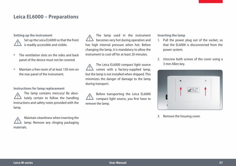
Inserting the lamp1. Pull the power plug out of the socket, so
that the EL6000 is disconnected from the power system.
2. Unscrew both screws of the cover using a 3 mm Allen key.
3. Remove the housing cover.
Leica EL6000 – Preparations

Leica M-series User Manual 58
Leica EL6000 – Preparation (cont'd.)
4. Carefully lay the Leica EL6000 on its side so that the opening faces you.
This makes it easier to insert the lamp.
5. Pull the pressure bolt back towards the front plate using the lever.
6. Insert the lamp.
Ensure that the groove in the contact surface of the lamp matches up with the corresponding plug in the lamp mount.

Leica M-series User Manual 59
Leica EL6000 – Connection to the Fluorescence Lamp Housing
• Always connect the light guide to the lamp housing of the stereomicroscope
in order to prevent danger to the user from the high-energy light.
1. Unscrew the positioning screw and remove the protective cover of the fluorescence lamp housing.
2. Insert the adapter into the fluorescence lamp housing and retighten the locking screw.
3. Unscrew the three red protective caps on the light guide.
4. Insert the short end of the light guide into the lamp housing of the stereomicroscope as far as it will go.
5. Securely tighten the clamping screw.

Leica M-series User Manual 60
Leica EL6000 – Preparation (cont'd.)
7. When the lamp makes full contact with the lamp mount, release the lever.
8. Connect the plug of the lamp with the coupling in the instrument.
Ensure that no wires are touching the reflector of the lamp.
9. Check to make certain that a heat-absorb-ing filter has been inserted into the shaft in order to protect the connected light guide.
10. Close the housing cover and insert the screws.

Leica M-series User Manual 61
Leica EL6000 – Replacing the Lamp
The procedure for replacing the lamp does not differ from the installation procedure outlined on Page 57, except for the fact that the existing lamp has to be removed first.
Replacing the lamp
The lamp used in the instrument becomes very hot during operation and
has high internal pressure when hot. Before changing the lamp, it is mandatory to allow the instrument to cool off for at least 20 minutes.
1. Pull the power plug out of the socket, so that the EL6000 is disconnected from the power system.
2. Unscrew both screws of the cover using a 3 mm Allen key.
3. Remove the housing cover.
4. Carefully lay the Leica EL6000 on its side so that the opening faces you.
This makes it easier to insert the lamp.
5. Pull the pressure bolt back towards the front plate using the lever.
6. Pull out the lamp and disconnect the plug from the coupling in the instrument.
7. Install the new lamp as outlined on Page 58, beginning with item 6.

Leica M-series User Manual 62
Leica EL6000 – Connection to the Fluorescence Lamp Housing (cont'd.)
6. Insert the long end of the light guide into the light output of the Leica EL6000. There must be a noticeable click.
• Only use a light guide with a light input of the type "Storz long", as otherwise
damage to the instrument and danger to the user can result (risk of being dazzled).
• Before you open the shutter, the light guide must be connected on both
sides. Otherwise, the escaping light can cause injury to eyes and skin and damage to furni-ture. Never look into the light escaping from the light guide!
5. Connect the Leica LA6000 to the power system using the power cable.

Leica M-series User Manual 63
Quick Start Guide
Leica M-series User Manual 64
The Fastest Route to Success
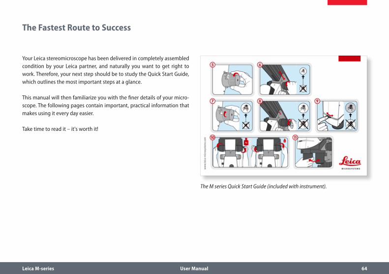
Your Leica stereomicroscope has been delivered in completely assembled condition by your Leica partner, and naturally you want to get right to work. Therefore, your next step should be to study the Quick Start Guide, which outlines the most important steps at a glance.
This manual will then familiarize you with the finer details of your micro-scope. The following pages contain important, practical information that makes using it every day easier.
Take time to read it – it's worth it!
The M series Quick Start Guide (included with instrument).

Leica M-series User Manual 65
Overview of an M Series Microscope
1 Eyepieces for spectacle wearers with dioptric correction and eyecups
2 Trinocular tube3 Fluorescence housing4 Filter Changer5 Display6 Motorized Focus7 Objective Nosepiece8 Leica SmartTouch 9 UV protection screen
1
2
34
5
7
9
8
6
Leica M-series User Manual 66
The Correct Interpupillary Distance
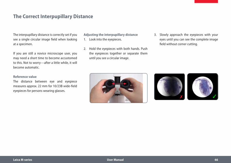
The interpupillary distance is correctly set if you see a single circular image field when looking at a specimen.
If you are still a novice microscope user, you may need a short time to become accustomed to this. Not to worry—after a little while, it will become automatic.
Reference valueThe distance between eye and eyepiece measures approx. 22 mm for 10/23B wide-field eyepieces for persons wearing glasses.
Adjusting the interpupillary distance1. Look into the eyepieces.
2. Hold the eyepieces with both hands. Push the eyepieces together or separate them until you see a circular image.
3. Slowly approach the eyepieces with your eyes until you can see the complete image field without corner cutting.

Leica M-series User Manual 67
If you wear glasses:1. Hold the eyepiece firmly and rotate the
eyecups clockwise towards the rear, as otherwise the viewing distance is too great.
2. If an eyepiece is equipped with the inte-grated dioptric correction, turn the value to the "0" mark.
By the way, one benefit of viewing with eyeglasses is a drastically lower risk of bacte-rial transmission (see Page 76). The soft mate-rial of the eyecup also ensures that your glasses will not be scratched, even if they contact the eyepiece.
Using the Eyepieces
If you do not wear glasses:1. Hold the eyepiece firmly and rotate the
eyecups forwards counterclockwise.
2. If an eyepiece is equipped with the inte-
grated dioptric correction, turn the value to the "0" mark.
The eyepieces form the connection between the tube and the eye of the observer. Simply push them into the tube and they are ready to use.
Each eyepiece offers a certain magnification factor that has a determinative effect on the total magnification. Furthermore, all Leica eyepieces can be equipped with practical grati-cules that enable measuring and quantifying of specimens.
Dioptric correctionA built-in dioptric correction is available for eyeglass wearers. For more information, refer to Page 77.
Leica M-series User Manual 68
Focusing
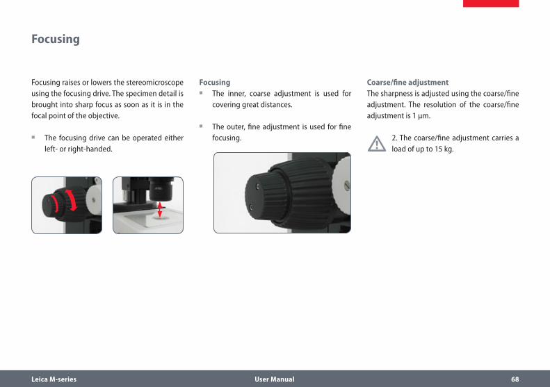
Focusing raises or lowers the stereomicroscope using the focusing drive. The specimen detail is brought into sharp focus as soon as it is in the focal point of the objective.
The focusing drive can be operated either ρ
left- or right-handed.
FocusingThe inner, coarse adjustment is used for ρ
covering great distances.
The outer, fine adjustment is used for fine ρ
focusing.
Coarse/fine adjustmentThe sharpness is adjusted using the coarse/fine adjustment. The resolution of the coarse/fine adjustment is 1 µm.
• 2. The coarse/fine adjustment carries a load of up to 15 kg.

Leica M-series User Manual 69
Adjusting the Resistance of the Focus Drive
Adjusting the resistanceIs the focus movement too loose or too tight? Does the outfit tend to slide downwards? The resistance can be adjusted individually depend-ing on the equipment weight and personal preferences as follows:
1. Grip the outer drive knobs with both hands and turn them towards each other until the desired resistance is reached during focusing.

Leica M-series User Manual 70
Changing Magnification (Zoom)
All M series microscopes have an integrated zoom. The name indicates the zoom range covered:
Leica M165 C = 16.5:1 ρ
Leica M205 C = 20.5:1 ρ
The rotary knob for the zoom can be used either left or right-handed.
Zooming1. Look into the eyepieces.
2. Focus on the specimen.
3. Rotate the magnification changer until the desired magnification is configured.

Leica M-series User Manual 71
The zoom button can optionally be operated either with or without ratchet steps. Continu-ous zoom is possible when the ratchet steps are disabled, which many users find convenient. On the other hand, when the ratchet steps are enabled, photographs, measurement results etc. can be reproduced more accurately.
Enabling and disabling ratchet steps1. Push the top button downwards to disable
the ratchet steps.
2. Push the bottom button upwards to enable the ratchet steps.
Magnifications and fields of viewThe formula on Page 147 provides additional information about the magnifications and field of view diameters, with consideration given to the position of the magnification changer and the eyepiece and objective combination used.
Ratchet Steps and Magnification Levels
Leica M-series User Manual 72
Parfocality: More Comfort and Convenience for Your Work
All Leica stereomicroscopes are parfocally matched, meaning that you can view a focused specimen from the lowest to the highest magnification without having to refocus. The focus needs only be readjusted if you want to see a specimen location that is located higher or lower.
Requirements for parfocal workIf you are using an eyepiece with dioptric ρ
correction, the procedure differs from this description. For more information, refer to Page 78.
For the procedure for adjusting the parfo- ρ
cality for the objective nosepiece, refer to Page 29.
For the procedure for adjusting the parfo- ρ
cality for the Leica FluoCombi III™, refer to Page 34.
Parfocality1. Enlarge the view to the maximum level.
2. Focus on the specimen.
You are done! Even if you select a smaller work-ing distance, the specimen remains pin-sharp.
The parfocality is maintained until you focus on another level of the specimen.

Leica M-series User Manual 73
The iris diaphragm in the optics carrier of your M series microscope fulfills the same purpose as the iris diaphragm in a camera: it regulates the available light, which changes the depth of field. The "depth of field" (or "focus depth") is the area of a specimen that is brought into sharp focus.
Closing the iris diaphragmClose the iris diaphragm by turning the ρ
knob to the left. The subject appears darker and the depth of field increases.
Opening the Iris DiaphragmOpen the iris diaphragm by turning the ρ
knob to the right. The subject now appears brighter, but the depth of field decreases.
Iris Diaphragm

Leica M-series User Manual 74
Eyepieces

Leica M-series User Manual 75
Magnification Factors of the Eyepieces
An eyepiece not only makes it possible to look passively into the micro-scope, but also has a critical effect on the maximum magnification. The magnification factor is between 10x and 40x.
The following eyepieces are available for the M series:
Magnification Dioptric correction Order number
10× ± 5 diopter settings 10 450 023
16× ± 5 diopter settings 10 450 024
25× ± 5 diopter settings 10 450 025
40× ± 5 diopter settings 10 450 026

Leica M-series User Manual 76
Health Notes
Potential sources of infection
• Direct contact with eyepieces is a potential transmission method for
bacterial and viral infections of the eye. The risk can be kept to a minimum by using individual eyepieces or detachable eyecups. Eyecups can be ordered separately. Please contact your Leica partner.
Separate eyecups are an effective way of preventing infections.

Leica M-series User Manual 77
All Leica eyepieces are also available with built-in dioptric correction, allowing the microscope to be used without glasses even by those with vision problems. The correction comprises ±5 diopter settings.
Using the Dioptric Correction1. Set the dioptric correction of both eyepieces
to the mid position ("0" diopter settings).
2. While wearing your glasses, look through the eyepieces and focus on the specimen.
3. Rotate both eyepieces to the maximum value of "+5".
4. Hold one eye closed and rotate the other eyepiece in the "-" direction until the speci-men appears sharp.
5. Then, open the other eye and correct the diopter settings until the image is uniformly sharp.
Note that when using dioptric correction, the advantage of parfocality is lost—thus
you have to manually refocus each time you change the zoom level. To also use parfocality with dioptric correction, refer to the instruc-tions on Page 78.
Dioptric Correction

Leica M-series User Manual 78
Adjusting1. Set the dioptric correction for both
eyepieces to "0".
2. Select the lowest magnification and focus on a flat specimen.
3. Select the highest magnification and read-just the sharpness.
4. Select the lowest magnification again, but do not look into the eyepieces.
6. Rotate the eyepieces counterclockwise in the "+" direction as far as they will go (+5 diopter settings).
Leica stereomicroscopes are parfocally matched. The prerequisite for this is the correct setting of the diopters and the parfocality. The following adjustments only have to be carried out once by each user.
PreparationsMove the lever of the video/phototube to ρ
the "observation" position and open the diaphragm.
If you are using the microscope carrier AX, ρ
set it to stereoscopic observation.
7. Look into the eyepieces.
8. Slowly rotate each eyepiece individually in the "–" direction until each eye sees the object sharply imaged.
9. Select the highest magnification and refocus if necessary.
Now, if you adjust the magnification from the lowest to the highest level, the specimen is always brought into sharp focus. If not, repeat the process.
Dioptric Correction and Parfocality

Leica M-series User Manual 79
Graticules
2. Clamp the graticule on the insert, applying moderate pressure. Ensure that the grati-cule fits tightly.
3. Screw the insert and graticule firmly into place and replace the eyepiece in the tube.
4. You can now align the graticule by rotating the eyepiece in the tube and then tighten-ing it using the clamping screw.
Use with the Leica AX carrier
If possible, measure with the micro-scope carrier AX in vertical position. The
measurements are more accurate without the convergence angle in the stereoscopic image.
UseLeica graticules make length measurements and counting easier, particularly for work-stations that are not equipped with a digital camera and LAS software.
The Leica graticules for length measurements and numbering are fitted in mounts and are inserted into the eyepieces.
1. Screw the insert off of the eyepiece.

Leica M-series User Manual 80
Photography & Video

Leica M-series User Manual 81
For most microscope users, digital documen-tation has become an invaluable part of their work. Research results can be presented in an attractive manner; measurements on the digital image provide clarity and, in conjunction with the motorized IsoPro™ mechanical stage, even images of large specimens can be captured step by step and automatically joined to create a new complete image.
AdapterIf camera control using the Leica Application Suite is not required, conventional mirror reflex and rangefinder cameras from third-party manufacturers can be used. For this purpose, Leica Microsystems offers a variety of adapters that can be used together with the 50% and 100% trinocular tubes.
Leica DFC camerasHowever, if you require absolute control over the camera and need the capability for measurement, evaluation and more in addition to photography, the digital Leica DFC cameras are exactly right for you. Together with the Leica Application Suite, they provide virtually limitless freedom of use. For additional informa-tion about Leica cameras, refer to the camera's documentation.
Leica Application SuiteThe "Leica Application Suite", or "LAS" for short, is, as it were, the digital extension of the Leica M series microscopes. In addition to capturing images, it lets you control the microscope, illu-minator, stages, cameras and more. For addi-tional information, refer to the LAS online help.
Photography & Video

Leica M-series User Manual 82
Photo Tubes and C-mounts
ApplicationAll Leica DFC cameras are equipped with a standardized C-mount interface. In turn, the C-mount adapter for the respective trinocular tube is connected to this interface. This adapter creates a solid mechanical connection between the microscope and camera and ensures opti-mum rendering of the microscopic image on the image sensor of the camera.
Usually, the ideal is for the digital camera to capture as much of the field of vision as possi-ble, while excluding as much of the black edge of the field of vision as possible. To do so, the magnification factor of the C-mount adapter must match the image format of the sensor as closely as possible (see table).
If there is unwanted shading at the corners even with a compatible C-mount adapter installed, it can be corrected using the "Shading function" of the camera software.
Alternatively, you can also use a C-mount adapter with higher magnification. This primar-ily avoids the critical border area of the field of vision and concentrates on the center of the field of vision.
Camera optimal (large
image field)
suitable (smaller
image field)
DFC290 0.5× 0.63×
DFC420 0.5× 0.63×
DFC490 0.63× 0.8×
DFC500 0.63× 0.8×
Cameras from third-party suppliersIn addition to Leica DFC cameras with the stan-dardized C-mount interfaces, you can connect third-party cameras to the microscope using a T2 bayonet adapter. To do so, instead of the C-mount adapter, simply use the correspond-ing SLR adapter with T2 connection. However, these third-party cameras are not integrated into the Leica Application Suite and have to be operated using the corresponding software from the camera manufacturer.
The Leica digital cameras are detailed in a sepa-rate user manual along with instructions for their assembly and use.

Leica M-series User Manual 83
Trinocular Video/Phototube 50%
UseWith its third beam path, the trinocular video/phototube 50% enables you to simultaneously view and photograph a specimen. The available light is divided as follows:
50% is available for the two eyepieces. ρ
50% of the light is diverted to the video/ ρ
photo beam path.
AssemblyFasten the "trinocular tube 50%" to the optics carrier instead of the binocular observation tube (refer to Page 24).
Leica M-series User Manual 84
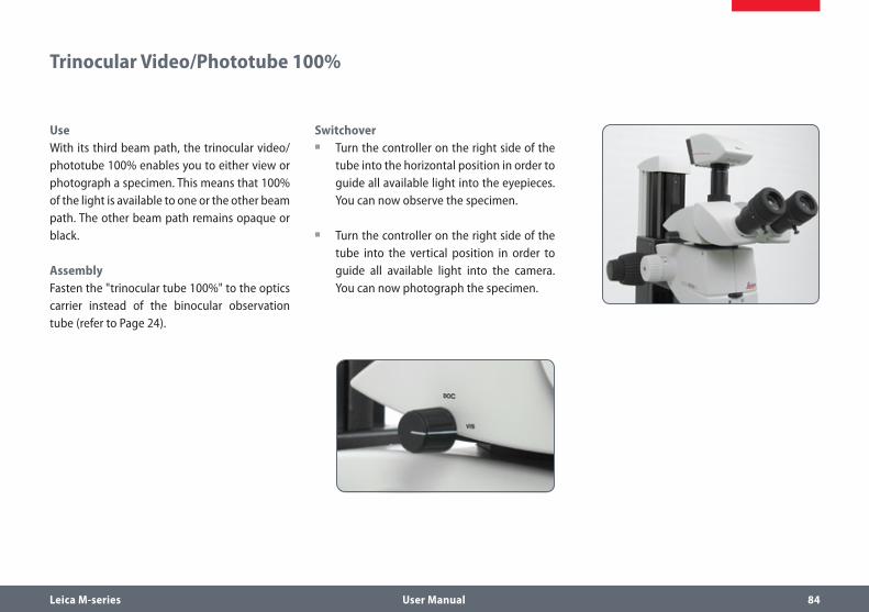
UseWith its third beam path, the trinocular video/phototube 100% enables you to either view or photograph a specimen. This means that 100% of the light is available to one or the other beam path. The other beam path remains opaque or black.
AssemblyFasten the "trinocular tube 100%" to the optics carrier instead of the binocular observation tube (refer to Page 24).
Switchover Turn the controller on the right side of the ρ
tube into the horizontal position in order to guide all available light into the eyepieces. You can now observe the specimen.
Turn the controller on the right side of the ρ
tube into the vertical position in order to guide all available light into the camera. You can now photograph the specimen.
Trinocular Video/Phototube 100%

Leica M-series User Manual 85
Microscope Carrier

Leica M-series User Manual 86
UseThe objective nosepiece enables you to switch between two objectives using just one hand movement, for example between a 1× and a 2× planapochromat.
Parfocal workWith the new M series objectives, the parfo-cality is maintained even when objectives are changed, meaning that the specimen remains in sharp focus during the change.
Older Leica objectives can continue to be used, but without parfocality during the
objective change.
Technical constraints
• The objective nosepiece cannot be used together with the LED5000 MCI™
system illumination, as the objective nosepiece can no longer be rotated.
The Objective Nosepiece

Leica M-series User Manual 87
Objectives and Optical Accessories
Leica M-series User Manual 88
The Different Types of Objectives
To meet the various requirements regarding imaging properties, there is a choice of high-quality interchangeable planachromatic and planapochromatic objectives and also lower-priced interchangeable achromatic objectives.
Achromatic objectives are particularly ρ
suited for specimens with high-contrast structures.
Flat-field (planachromatic) objectives are ρ
particularly well suited for studying flat objects such as wafers and thin sections.
With planapochromatic objectives, the ρ
finest structures are visible with high contrast. The sophisticated apochromatic correction allows these objectives to attain the highest color brilliance and fidelity.
Achromatic objectivesThe 0.32×, 0.5×, 0.63×, 0.8×, 1×, 1.5×, 2× achromatic objectives offer countless variants for selecting the object field diameter, magni-fication ranges and working distances (see Page 147).
Planachromatic objective 1×For the highest requirements for overall image quality, we recommend equipping the micro-scope with the 1× plan (flat-field) objective, which returns sharp, contrast-rich object fields.
Achromatic objectives with a long focal lengthFor special applications, achromatic objectives with long working distances and focal lengths of f=100 mm to 400 mm are available.

Leica M-series User Manual 89
Bases

Leica M-series User Manual 90
Leica TL ST Transmitted-light Base: Controls
1 Adapter plate for easy assembly of focusing drives
2 Removable glass plate3 Controller for light intensity4 Adjustment for deflection mirror
Rear side of the transmitted-light base TL ST1 Screws for changing the halogen lamp2 Power connection socket3 Power switch
Extension plate of the transmitted-light base TL ST
1
2
3
4
1 2 3

Leica M-series User Manual 91
Leica TL ST Transmitted-light Base: Operation
Light intensity controlThe left control adjusts the intensity of the 12 V/20 W halogen illumination.
1. Switch on the illumination of the base at the power switch.
2. Focus on the specimen.
3. Set the illumination to the desired intensity using the left control.
Transmitted-light controlThe transmitted-light base TL BFDF has a slider that automatically moves the deflection mirror in the base when moved. The mirror is kept in the correct position at all times and permits smooth changeover between bright field and opaque transmitted light.
Bright fieldBright field is suitable for examining translu-cent objects featuring contrasting structures. The object is directly illuminated from below and is seen in its natural colors against a bright background.
Move the slider backwards until the desired ρ
effect is achieved.
Inclined transmitted lightTransmitted light that traverses the object obliquely will provide additional resolution and information when observing semitransparent, opaque objects.
Slowly pull the slider towards yourself until ρ
the desired effect is achieved.
Leica M-series User Manual 92
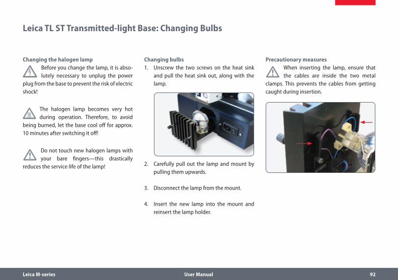
Changing the halogen lamp
Before you change the lamp, it is abso-lutely necessary to unplug the power
plug from the base to prevent the risk of electric shock!
The halogen lamp becomes very hot during operation. Therefore, to avoid
being burned, let the base cool off for approx. 10 minutes after switching it off!
• Do not touch new halogen lamps with your bare fingers—this drastically
reduces the service life of the lamp!
Changing bulbs1. Unscrew the two screws on the heat sink
and pull the heat sink out, along with the lamp.
2. Carefully pull out the lamp and mount by pulling them upwards.
3. Disconnect the lamp from the mount.
4. Insert the new lamp into the mount and reinsert the lamp holder.
Precautionary measures
• When inserting the lamp, ensure that the cables are inside the two metal
clamps. This prevents the cables from getting caught during insertion.
Leica TL ST Transmitted-light Base: Changing Bulbs

Leica M-series User Manual 93
Leica TL BFDF Transmitted-light Base: Controls
1 Adapter plate for easy assembly of focusing drives
2 Standard stage 10 447 2693 Button to toggle between bright field and
dark field
1
2
3 Extension plate of the Transmitted-light base TL BFDF
Adapter at the focusing drive
Button to toggle between bright field and dark fieldConnector for cold light sources(light conductor active f = 10mm, end tube f = 13mm)

Leica M-series User Manual 94
Light intensity control
• Observe the user manual—in particu-lar, all safety regulations—from the
manufacturers of the light guide and cold light source.
Switch on the cold light source according to ρ
the manufacturer's user manual and adjust the brightness.
Transmitted-light controlThe Leica TL BFDF transmitted-light base has a control that switches the light from "bright field" to "dark field".
Bright fieldBright field is suitable for examining translu-cent objects featuring contrasting structures. The object is directly illuminated from below and is seen in its natural colors against a bright background.
Turn the control as far as it will go towards ρ
"BF" ("bright field").
Dark fieldIn dark-field illumination, a ring illuminator is used in such a way that the direct light does not reach the objective without a specimen. Only the structure of semitransparent, opaque objects disperses the light, making the object visible against a dark background.
Turn the control as far as it will go towards ρ
"DF" ("dark field").
Leica TL BFDF Transmitted-light Base: Operation
Fingertip with bright field illumination Identical subject with dark field illumination
Leica M-series User Manual 95
Leica TL RC™ / TL RCI™: Controls
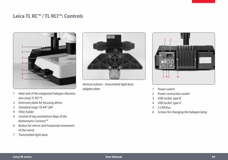
Vertical column - transmitted-light base adapter plate
1 Heat sink of the integrated halogen illumina-tion (only TL RCI™)
2 Extension plate for focusing drives3 Standard stage 10 447 2694 Filter holder5 Control of top and bottom flaps of the
Rottermann Contrast™6 Button for mirror and horizontal movement
of the mirror7 Transmitted-light base
1
2
3
4
567
1
3 4 5 6
2
1 Power switch2 Power connection socket3 USB socket, type B4 USB socket, type A5 2 CAN bus6 Screws for changing the halogen lamp

Leica M-series User Manual 96
Leica TL RCI™: The Deflection Mirror
Inverted world?Depending on the properties of the specimen (refractive index of the environment) and the perception of the viewer, it is possible that the switches described below for positive and inverted relief contrast are to be operated in reverse. This means that the lower switch, rather than the upper switch, controls inverted the relief contrast and vice-versa.
Tilted mirrorThe built-in mirror features one flat and one concave side and can be rotated and moved. The concave side has been specially designed for the optical requirements of objectives with a high numerical aperture. The black rotary knob on the left side of the transmitted-light base can be used to rotate the built-in path-folding mirror and move it forwards/back.
The concave cutout on the handle indicates the concave side of the mirror, allowing intuitive operation at any time without eye contact.
The angle of light incidence in the specimen plane changes depending on the tilt and posi-tion of the mirror. As a result, switching between transmitted light bright field, oblique illumina-tion and dark field-like illumination is possible.
Functions of the rotary knobThe rotary knob (1) fulfills the following tasks:
Turning the deflection mirror from the flat ρ
to the concave side
Slight tilting to guide the light beam ρ
through the specimen plane at a steeper or flatter angle
Moving the deflection mirror (forwards/ ρ
back)
1

Leica M-series User Manual 97
Leica TL RCI™: Color Intensity and Temperature
1 Potentiometer for controlling the CCIC™ (Constant Color Intensity Control) illumina-tion intensity
2 Potentiometer for controlling the color temperature
The transmitted-light base TL RCI™ has two electronic potentiometers that control the color intensity (1) and color temperature (2).
The controller for the color temperature simul-taneously serves as an electronic shutter:
To interrupt your work, click the potentiom- ρ
eter (2).
Click again to switch on the illumination. ρ
The electronics returns the color tempera-ture to the previously configured settings.
1 2
Using a USB mouse (only TL RCI™)The Leica USB mouse controls the CCIC™ and dimming function of the TL RCI™ base. Connect the mouse to the corresponding USB port of the base.
The scroll wheel of the mouse is occupied ρ
by default with the CCIC™ control system and is used to control the illumination intensity.
To switch the illumination on or off, briefly ρ
click the scroll wheel.
To enter or exit dimming mode, click and ρ
hold down the scroll wheel for longer than 2 seconds.

Leica M-series User Manual 98
Setting the relief contrastThe two switches on the left side of the trans-mitted-light base TL RC™/TL RCI™ activate two built-in flaps. The outer switch (1) controls the inverted relief contrast, and the inner switch (2) adjusts the positive relief contrast.
Depending on the flap position, a part of the opening of the built-in Fresnel lenses are covered, which results in the different contrast effects. Phase structures typically act as spatial, relief-type images—in the positive relief contrast like hills, in the inverted relief contrast like valleys.
Increased contrast without relief is attained if both diaphragms are set to 45°. A gap-like illuminated area is created. By tilting the deflec-tion mirror slightly, you can move the gap over the entire field of view and quickly toggle between positive and negative relief images. The dynamic effect makes it easy to distinguish phase structures from amplitude structures.
Leica TL RC™ / TL RCI™: Operation
1 Switch for adjusting the inverted relief contrast
2 Switch for adjusting the positive relief contrast
3 Deflection mirror
1 2 3

Leica M-series User Manual 99
Leica TL RCI™: Methods in Transmitted Light
Vertical bright-field illumination Suitable for stained amplitude specimens with sufficient contrast.
The light beams are deflected vertically through the specimen. This results in an accurate bright field with maximum brightness.
Inclined transmitted light Suitable for semitransparent, opaque speci-mens such as foraminifera and fish eggs. Move the deflection mirror until the desired data are visible.
Single-sided dark fieldSuitable for fixed specimens and fine struc-tures.
The flatter the angle at which the light beams are deflected into the specimen plane, the darker the substrate appears. A dark field-like transmitted light is created. Outlines, fine edges and structures are bright, in contrast with the dark background, through diffraction of the light beams on the dark background.
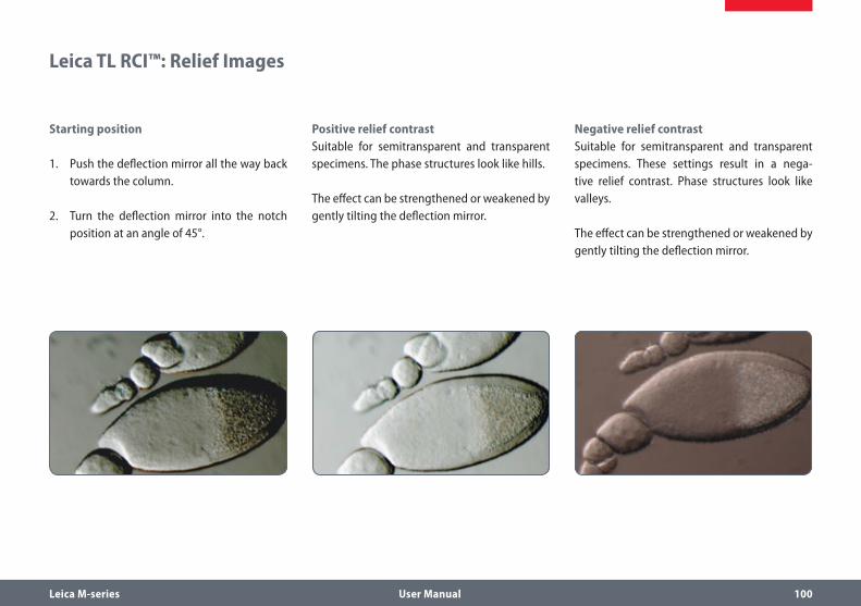
Leica M-series User Manual 100
Leica TL RCI™: Relief Images
Starting position
1. Push the deflection mirror all the way back towards the column.
2. Turn the deflection mirror into the notch position at an angle of 45°.
Positive relief contrastSuitable for semitransparent and transparent specimens. The phase structures look like hills.
The effect can be strengthened or weakened by gently tilting the deflection mirror.
Negative relief contrastSuitable for semitransparent and transparent specimens. These settings result in a nega-tive relief contrast. Phase structures look like valleys.
The effect can be strengthened or weakened by gently tilting the deflection mirror.

Leica M-series User Manual 101
Dynamic relief contrastSuitable for semitransparent and transparent specimens.
By tilting the deflection mirror slightly, you can move the gaps over the entire field of view and quickly toggle between positive and negative relief images. The dynamic effect makes it easy to distinguish phase structures from amplitude structures.
ConstraintsThe relief methods provide good results from mid-zoom to high magnifications and with 1×, 1.6× and 2× objectives. In the lower zoom half and with weaker specimens, the object field may not be uniformly illuminated.
We recommend using the transmitted-light base with 1× or higher objectives, and not objectives with a long focal length.
Leica TL RCI™: Relief Images (cont'd.)

Leica M-series User Manual 102
Filters for Leica TL RC™ and TL RCI™The transmitted-light bases TL RC™ and TL RCI™ can be equipped with up to three filters—available as accessories—simultaneously. By customer request, the filters are also available as one-off items.
1. Switch off the light source or click (Leica TL RCI™) the button for the shutter.
2. Take the empty filter from an available filter slot in the filter holder.
3. Insert the desired filter.
4. Switch the light source back on.
Daylight filter for Leica TL STA daylight filter is also available for the Leica TL ST transmitted-light base.
Using Filters

Leica M-series User Manual 103
Leica IsoPro™ (Non-motorized): Controls
Operating the Leica IsoPro™ mechanical stage 1. To move the stage in the X direction, rotate
the outer knob.
2. To move the stage in the Y direction, rotate the inner control ring.
1 2

Leica M-series User Manual 104
Leica IsoPro™ (Motorized): Controls
1 Leica IsoPro™ motorized mechanical stage2 Housing with motorization
1 Sub-D interface for Leica SmartMove™2 3 CTL2 interfaces3 USB interface (type B)4 Socket for grounded power cable
1 Quick control/memory function2 Fine control in X direction3 Fine control in Y direction
1 2
1 2 3 4
IsoPro X/Y Stage DCI module Leica PSC Controller
2
1
3

Leica M-series User Manual 105
System Illumination

Leica M-series User Manual 106
UseThe Leica LED5000 MCI™ (for "Multi Contrast Illumination") is a universal high-output illu-minator. Three groups of 3 LEDs each can be arranged as desired around the specimen. The targeted control of the LEDs enables various illumination scenarios to be implemented.
PreparationHold the MCI with both hands and pull it down-wards until the illuminator clicks into place on the bottom end of the guide rods.
In this position, you always have the same contrast with identical illumination. This guar-antees the reproducibility of an experiment.
Contact with the base
• If the optics carriers are accidentally lowered too far, contact between the
base and MCI may result. A safety mechanism in the linkage ensures that, in this case, the MCI is automatically pushed upwards to prevent the possibility of damage.
Be sure not to place any specimens directly ρ
beneath the MCI.
After the optics carrier is lifted, put the MCI ρ
back into the original position.
Leica LED5000 MCI™
Installed too high
Optimum height

Leica M-series User Manual 107
Using the keyboardUse the ρ key to switch the illumination on or off.
Use the "+" and "–" keys to adjust the ρ
brightness in 10 increments. Touch either of the two buttons to adjust the intensity in small increments. Hold a key to change the intensity more quickly.
The illumination scenariosUse the " " and " " keys to toggle between the illumination scenarios shown below.
Maximum brightnessFor temperature reasons it is not possible to switch on all nine LEDs simultaneously. There-fore, to provide bright overall illumination, the top two rows are activated. The bottom row primarily provides contrast.
The Leica LED5000 MCI™ can also be controlled by the LAS (Leica Application Suite) software.
Leica LED5000 MCI™ (cont'd.)
Maximum brightness Point illumination from the right
Maximum contrast Point illumination from the left
Point illumination from the rear

Leica M-series User Manual 108
Leica LED5000 RL
UseThe Leica LED5000 RL ("Ring Light") generates a very bright and homogenous incident light. It has a diameter of 80 mm and illuminates the specimen with 48 LEDs that can be switched on and off completely or in various combinations. It is controlled using either the integrated or via the Leica Application Suite (LAS).
LAS enables you to create fully reproducible illumination scenarios and automatically toggle between them. For additional information, refer to the LAS online help.
Using the keyboardUse the ρ key to switch the illumination on or off.
Use the "+" and "–" keys to adjust the ρ
brightness in 10 increments. Touch either of the two buttons to adjust the intensity in small increments. Hold a key to change the intensity more quickly.
The illumination scenariosUse the " " and " " keys to toggle between the illumination scenarios shown below.
ConstraintThe Leica LED5000 RL has been designed for use with the 1.0× and 0.63× objectives. For the 1.6× and 2.0× objectives, conventional ring illuminators from the Leica illuminator product range are available.

Leica M-series User Manual 109
The Leica EL6000 compact light source is intended for biological routine and research work, including the examination of specimens from the human body for the purpose of gain-ing information.
• The Leica EL6000 compact light source is intended exclusively for
operating mercury short-arc lamps of type HXP-R120W/45C VIS from OSRAM in conjunc-tion with a suitable light guide for the instru-ment. Any other use of the instrument shall be considered noncompliant use.
Special features:The Leica EL6000 compact light source has an automatic beam cover. This ensures that the light beam output of the instrument when the light guide is detached. This prevents the user from being harmed by the intense light beam generated by the instrument.
The Leica EL6000 compact light source has a built-in shutter. It can be operated at the instru-ment itself by means of a pushbutton or via a remote control input. The shutter is open when the "open" LED is illuminated.
The brightness can be varied in 5 increments (0% – 100%). For this purpose, a mechanical dimming unit that can be operated using a rotary switch on the front of the unit is installed in the device.
Heat-absorbing filterWhen the cover is open, the holder for the heat filter can be accessed. Here, (hardened) heat-absorbing filters for protecting the light guide and various conversion filters with a diameter of 32 mm for adapting the spectrum to the application can be inserted.
The Leica EL6000 comes factory-equipped with a heat-absorbing filter.
Leica EL6000 – About the Instrument

Leica M-series User Manual 110
Leica EL6000 – About the Instrument (cont'd.)
Compatible light guidesThe Leica EL6000 compact light source is compatible with liquid light guides that are compatible with a "Storz long" light inlet and whose transmission curve fits the lamp used. Where applicable, refer to the lamp's data sheet for its spectral light distribution.
When connecting the light guide to the light source or the microscope adapter, make sure not to kink or damage the light guide.
Your Leica consultant will be glad to provide additional information about suitable light guides.
Identification of the instrumentThe nameplate of the instrument is on its bottom. It includes the necessary information for identifying the instrument.
The Leica EL6000 compact light source complies with Council Directive 98/79/EC concerning in vitro diagnostics. It also conforms to the Coun-cil Directives 73/23/EEC concerning electrical apparatus and 89/336/EEC concerning electro-magnetic compatibility for use in an industrial environment.

Leica M-series User Manual 111
Leica EL 6000 – Operation
Controls Running-time meterThe running-time meter measures the burn-ing time of the lamp, not the switch-on time of the Leica EL6000 compact light source. The running-time meter displays its current status in this format: hours – minutes.
1. Press the reset button to set the running-time meter of the lamp to "0".
The running-time meter should be reset after every lamp replacement so that it always displays the current, accurate lamp life.
Discontinue using the built-in lamp when it reaches the end of the life specified by the manufacturer.
Shutter controlIn the "open" position, the shutter of the ρ
Leica EL 6000 is open—regardless of the signal from the remote control.
If the shutter control is in the "remote" posi- ρ
tion, the shutter is controlled by the remote control.
Intensity switchThe intensity switch provides optical dimming of the light in five fixed increments.
1 Power switch/power indicator2 Reset button for running-time meter3 Running-time meter4 Shutter control5 Intensity switch
13 24
5

Leica M-series User Manual 112
Leica EL 6000 – Troubleshooting
Fault description Possible faults Remedy
Power indicator is not illuminated after being switched on, instrument shows no function
No power supply voltage present; connecting cable not plugged in correctly/defective
Check power supply voltage and connecting cable
Fuses in instrument defective Replace fuses, use permitted replacement type only (see Page 113)
Power switch is illuminated after being switched on, instrument shows no function
Housing cover loose or removed
Attach housing cover securely
Lamp worn out Replace lamp
Target system receives too little light or none at all
Shutter closed or intensity switch at left limit stop
Open shutter or rotate intensity switch towards the right
Light guide not inserted into light guide output properly
Check light guide
Light guide damaged/defective Repair or replace
If these actions do not fix the problem, send the Leica EL6000 compact light source to Leica service with an exact description of the malfunction.

Leica M-series User Manual 113
Cleaning and Maintenance
• Before carrying out cleaning tasks, switch off the Leica EL6000 compact
light source.
Use only a dry, lint-free cloth for cleaning. When cleaning, ensure that no dust or other foreign bodies enter the device through the ventilation slots.
In case of damage (even external damage), immediately stop using the Leica EL6000 compact light source and send it to service.
If it will not be used for a long time, protect the Leica EL6000 compact light source from dust using a suitable cover (such as the plastic bag from the original packaging).
Spare parts and accessoriesThe only parts of the Leica EL6000 compact light source that may be replaced by the user are the instrument fuses and the lamp.
The replacement of the lamp is described on Page 61.
Replacing the instrument fuse1. Disconnect the Leica EL6000 from the
power supply.
2. Open the drawer with the instrument fuses located close to the power supply input.
3. Replace the instrument fuse.
RepairsOpening or working on the Leica EL6000 compact light source in any manner other than described above (changing lamps, changing fuses) may be carried out by the supplier of the instrument or the supplier's authorized repre-sentatives.
Permitted replacement fuses
Fuse: 5×20, 2.5 A, slow-blowing, breaking capacity H
Wickmann Series 181 www.wickmann.com
Schurter Series SPT 5×20 www.schurter.ch

Leica M-series User Manual 114
Fluorescence

Leica M-series User Manual 115
Filter Changer
The patented FLUOIII® filter system consists of a filter changer for barrier and excitation filters, a UV shutter that can be activated/deactivated, and a filter insert for a filter holder with your choice of filter.
The filter changer can hold a total of 4 filter sets. The filter sets for fluorescence are labeled (see Page 118). All filter sets are equipped with a tran-sponder for automatic filter detection and can also be used with the motorized Leica M205 FA.
The scope of delivery of the Leica M205 FA and Leica M165 FC includes three simple filter hold-ers without fluorescence for empty filter posi-tions and transmitted or incident light observa-tion without fluorescence. These filter holders have two empty openings for the observation beam paths. The third opening, to the illumina-tion beam path, is closed.
• If you are using fewer than four filter holders with fluorescence filters, always
insert the included simple filter holders with closed illumination beam path into the avail-able positions. Otherwise, there is a risk of danger to the eyes from direct UV radiation from the third beam path.
The simple filter holders also protect the system from dust.
Filter sets for fluorescenceThe filter sets for fluorescence contain, on one filter holder, two barrier filters to the visual beam paths and one excitation filter to the illu-mination beam path. The fluorescence filters have a transponder with the specific filter data for use with the motorized Leica M205 FA. The filter sets are labeled (see Page 118).
A selection of the available filters including simple filter holder (bottom right)

Leica M-series User Manual 116
FIM – Fluorescence Intensity Manager
FIM consists of a diaphragm disk with pinhole diaphragms of varying transmission capaci-ties. The intensity of the excitation light can be reduced in five fixed steps. The light can be changed from 100% to 55%, 30% and 17% down to 10%.
The advantage of this procedure is its absolute reproducibility and fast switching between the intensity levels. A separate FIM level can be stored for every fluorescence filter. Different intensities of fluorescence can thus be cali-brated to one another.

Leica M-series User Manual 117
About Fluorescence Microscopy
Functional principleFluorescent substances light up when irradi-ated with short-wave excitation light, and fluo-rescence microscopy takes advantage of this property. Specimens without self-fluorescence are stained with a fluorescent substance. One such dye is green fluorescent protein (GFP), which is used in molecular biology.
The Leica M SeriesThe Leica M series fluorescence stereomicro-scopes allow entire fluorescent specimens to be studied, unprepared and in three dimen-sions. The fully apochromatic optics system and the enormous zoom range make the Leica M series stereomicroscopes your first choice. The patented TripleBeam® third beam path for fluo-rescence illumination and the patented FLUOIII® filter system generate highest-quality fluores-cence images. The very bright high-pressure mercury burner and specially selected filter sets enable you to distinguish the finest structures and enhance the quantity of information for incident light fluorescence.
The filter systemThe FLUOIII® filter system consists of a rapid filter changer for barrier and excitation filters and a filter insert for a filter holder with your choice of filter. A total of four filter sets (which are labeled) can be used in the rapid filter changer. An empty filter cartridge is also avail-able for individual filter combinations. Each filter set includes two barrier filters to the visual beam paths and an excitation filter to the illu-mination beam path.

Leica M-series User Manual 118
Rapid Filter Changers and Filter Types
Filter sets Excitation filter Barrier filter Designation
GFP 425/60 nm (395–455 nm) 480 LP GFP1
GFP Plus 480/40 nm (460–500 nm) 510 LP GFP2
GFP plants 470/40 nm (450–490 nm) 525/50 nm (500–550 nm) GFP3
UV 360/40 nm (340–380 nm) 420 LP UV
Violet 425/40 nm (405–445 nm) 460 LP V
Blue 470/40 nm (450–490 nm) 515 LP B
Green 546/10 nm (541–551 nm) 590 LP G
CFP 436/20 nm (426–446 nm) 480/40 nm (460–500 nm) CFP
YFP 510/20 nm (500–520 nm) 560/40 nm (540–580 nm) YFP
Texas Red 560/40 nm (540–580 nm) 610 LP TXR
DsRED 545/30 nm (510–560 nm) 620/60 nm (590–650 nm) DSR
CY5 620/60 nm (590–650 nm) 700/75 nm (663–737 nm) CY5
CY3 555/60 nm (530–580 nm) 610/75 nm (573–648 nm) CY3
The rapid filter changer must be equipped with four filter holders at all times.

Leica M-series User Manual 119
Simple filter holders
Simple filter holders Three simple filter holders are included with the Leica M165 FC and the Leica M205 FA. These filter holders have two empty openings for the observation beam paths. The third opening, to the illumination beam path, is closed.
Use this filter holder if you want to work ρ
briefly (no more than 15 seconds) without fluorescence illumination.
So that the filter holder is not heated, it must not block the mercury light for
longer than 15 seconds.
Safety NotesIf you want to block the mercury light for ρ
longer than that, activate the UV shutter.
Use the filter if you want to change to trans- ρ
mitted light or incident light observation without fluorescence.
Always place a simple filter holder into the ρ
empty filter changer positions in order to protect yourself from UV radiation and protect the system from dust.
• If you are using fewer than four filter holders with fluorescence filters, always
insert the included simple filter holders with closed illumination beam path into the avail-able positions. Otherwise, there is a risk of danger to the eyes from direct UV radiation from the third beam path.

Leica M-series User Manual 120
Equipping the Filter Changer
• When inserting the filter sets, avoid touching the filters in order to avoid
fingerprints. Clean dirty filters immediately using a soft, lint-free cloth and pure alcohol.
Removing the simple filter holderThe Leica M165 FC and the Leica M205 FA are equipped at the factory with simple filter hold-ers as "dummies". These must be removed before inserting a filter.
1. Grasp the recess of the dummy in the filter changer and pull it out.
Inserting the filter1. Place the filter into the filter changer.
Ensure that the contour of the filter holder matches the contour of the microscope.
2. Rotate the filter changer by hand until it latches into place.
If the filter holder has not been inserted correctly, the filter changer does not rotate.
3. Insert a total of four filters.
Slot for filter slideThere is a slot in the filter changer system for an individually selectable filter, for example a neutral density filter.
Leica M-series User Manual 121
Observation without Fluorescence
We recommend that you first familiarize yourself with the controls of your Leica
fluorescence microscope in transmitted light without the presence of fluorescence illumina-tion.
• After switching on the high-pressure mercury burner, you must adjust the arc
lamp immediately (see User Manual M2-216-1).
We recommend that you first familiarize yourself with the basic functions of your
Leica stereomicroscope as they are described in the previous section of this User Manual. These include the binocular tube, the eyepieces, the zoom magnification changer, the focusing drive, and others.
The following describes the specific functions of the fluorescence system only.
Observation without FluorescenceThe FLUOIII® filter system includes a UV shutter that can be used to close the illumination beam path. This feature protects the mercury lamp, which should not be switched on and off too frequently. If, for instance, you need to inter-rupt your work, you do not have to switch off the high-pressure mercury burner to preserve sensitive specimens from being burned out or bleached out.
Switching the high-pressure mercury burner on and off frequently decreases
its life and causes delays, as the lamp can only be switched back on after it has cooled. Instead, you can close the UV shutter and reopen it when you return to your workplace.
Close the UV shutter when you do not want to view the specimen with fluorescence illumina-tion, but only with transmitted light.
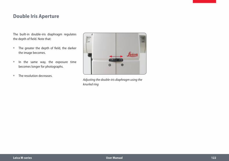
Leica M-series User Manual 122
Double Iris Aperture
The built-in double-iris diaphragm regulates the depth of field. Note that:
The greater the depth of field, the darker ρ
the image becomes.
In the same way, the exposure time ρ
becomes longer for photographs.
The resolution decreases. ρAdjusting the double-iris diaphragm using the knurled ring

Leica M-series User Manual 123
Commissioning the Fluorescence System
After switching on the high-pressure mercury burner, you must adjust the arc lamp imme-diately (see User Manual M2-216-1). Do not switch on the supply unit until you feel confi-dent using the Leica stereomicroscope.
• Follow all safety instructions when handling mercury lamps and the lamp
housing!
1. Switch on the supply unit (see User Manual M2-216-1).
2. Wait 2–3 minutes.
3. Adjust the arc lamp in accordance with User Manual M2-216-1.
• For observation with fluorescence light, always position the protection screen
correctly to protect the observer (see Page 27).

Leica M-series User Manual 124
Accessories

Leica M-series User Manual 125
With its non-slip controllers and knobs, the Leica SmartMove control unit offers the right feel for handling motorized Leica instruments.
ControlsThe functions of the individual controls can be configured both directly on the Leica Smart-Move and using the Leica Application Suite.
For a detailed description of the functions and settings, please refer to the Leica SmartMove manual or the Leica Application Suite help file.
Leica SmartMove

Leica M-series User Manual 126
With the touchscreen of the Leica SmartTouch™, you can control your experiment procedures with a few hand movements and never lose sight of all your important optical parameters.
The most important control functions on the control unit can be adjusted to your specific needs with freely programmable rotary knobs and function buttons.
ControlsThe functions of the individual knobs and screen elements can be configured both directly on the Leica SmartTouch™ and using the Leica Application Suite.
The standard configuration when shipped from the factory is as follows:
Leica SmartTouch™
Top part of the knob = zoom ρ
Upper part of the knob = focus ρ
Buttons = left filter, right filter, shutter ρ
For a detailed description of the functions and settings, please refer to the Leica SmartTouch™ manual or the Leica Application Suite help file.

Leica M-series User Manual 127
Leica PSC Controller
UseThe Leica PSC controller gives you precision control of the Leica IsoPro™ motorized mechan-ical stage.
ConnectionConnect the Leica PSC controller and the Leica IsoPro™ motorized mechanical stage to the DCI box.
Passing over the specimen quicklyMove the joystick in any desired direc- ρ
tion (including diagonally) to control the mechanical stage quickly.
Fine control of the mechanical stageThe motorized Leica IsoPro™ mechanical stage offers an accuracy of up to 0.25 µm. To move to a position with maximum accuracy, use the left and right knobs on the joystick.
Control by LASThe instructions for controlling the Leica IsoPro™ using the Leica Application Suite are provided in the software's help file.

Leica M-series User Manual 128
Dimensional Drawings
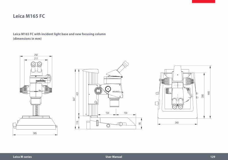
Leica M-series User Manual 129
Leica M165 FC
Leica M165 FC with incident light base and new focusing column (dimensions in mm)
385
154
340
390 44
0
95
154
116
431
547
292217
385
154
340
390 44
0
95
154
116
431
547
292217
385
154
340
390 44
0
95
154
116
431
547
292217

Leica M-series User Manual 130
Leica M165 FC (cont'd.)
Leica M165 C with TL RCI™ transmitted light stand, Leica IsoPro™ manual mechanical stage and manual focusing drive
497
292217
187154
max. 370
X = +-75 mm
370
95
300
249
Y =
+-50
mm
116
431
547
497
292217
187154
max. 370
X = +-75 mm
370
95
300
249
Y =
+-50
mm
116
431
547
497
292217
187154
max. 370
X = +-75 mm
370
95
300
249
Y =
+-50
mm
116
431
547

Leica M-series User Manual 131
Leica M165 FC (cont'd.)
Leica M165 C with TL RCI™ transmitted light stand and manual focus
340
430
85
154
356
154
292217
106
431
537
340
430
85
154
356
154
292217
106
431
537
340
430
85
154
356
154
292217
106
431
537

Leica M-series User Manual 132
Leica M205 FA
Leica M205 FA with TL BFDF transmitted light stand, ErgoTrinoc tube, DFC camera and motorized focusing drive
370
154
340
390
90
154
292
116
431
547
370
154
340
390
90
154
292
116
431
547
370
154
340
390
90
154
292
116
431
547
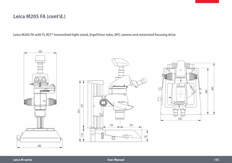
Leica M-series User Manual 133
Leica M205 FA (cont'd.)
Leica M205 FA with TL RCI™ transmitted light stand, ErgoTrinoc tube, DFC camera and motorized focusing drive
385
154
340
390 44
0
95
154
116
431
547
292 385
154
340
390 44
0
95
154
116
431
547
292385
154
340
390 44
0
95
154
116
431
547
292

Leica M-series User Manual 134
Leica M205 FA (cont'd.)
Dimensions of Leica M205 FA with TL RCI™ transmitted light stand, IsoPro™ mechanical stage, ErgoTrinoc tube, DFC camera and motorized focusing drive
497
187154
max. 410
X = +-75 mm
370
95
300
249
Y =
+-50
mm
292
116
431
547
497
187154
max. 410
X = +-75 mm
370
95
300
249
Y =
+-50
mm
292
116
431
547
497
187154
max. 410
X = +-75 mm
370
95
300
249
Y =
+-50
mm
292
116
431
547
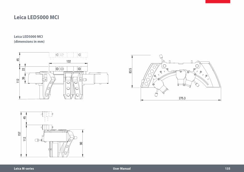
Leica M-series User Manual 135
Leica LED5000 MCI
132
275.3
157
83.5
112
4511
2
90
45
3622
132
275.3
157
83.5
112
4511
2
90
45
3622
132
275.3
157
83.5
112
4511
2
90
45
3622
Leica LED5000 MCI (dimensions in mm)

Leica M-series User Manual 136
Leica LED5000 RL
120
ø70 30
153
153
ø80

Leica M-series User Manual 137
MATS TL
190140
220 4
11
134
98170
10 447 164
10 447 275

Leica M-series User Manual 138
Specifications

Leica M-series User Manual 139
Leica M165 FC / Leica M205 FA
Leica M165 FC Leica M205 FA
Optical data
Zoom 16.5 : 1 manual 20.5 : 1 automated with FusionOptics™
Data with standard optics (1×objec-tive/10× eyepieces) – Zoom range – Resolution – Working distance – Object field
7.3×–120× max. 453 lp/mm 61.5 mm (planapochromat) ∅ 31.5 mm – 1.92 mm
7.8×–160× max. 525 lp/mm 61.5 mm (planapochromat) ∅ 29.5 mm – 1.44 mm
Maximum values (based on optics combi-nation) – Magnification – Resolution – Visible structural width – Numerical aperture – Object field
960× 906 lp / mm 551 nm 0.302 ∅ 63 mm
1280× 1050 lp / mm 476 nm 0.35 ∅ 59 mm
Working distances 135 mm (0.5× planachromat) 112 mm (0.8× planachromat) 67 mm (0.63× planapochromat) 61.5 mm (1× planapochromat) 30.5 mm (1.6× planapochromat) 20.1 mm (2× planapochromat)
135 mm (0.5× planachromat) 112 mm (0.8× planachromat) 67 mm (0.63× planapochromat) 61.5 mm (1× planapochromat) 30.5 mm (1.6× planapochromat) 20.1 mm (2× planapochromat)

Leica M-series User Manual 140
Leica M165 FC / Leica M205 FA (cont’d.)
Leica M165 FC Leica M205 FA
Optics carrier
100% apochromatic optical system CMO (Common Main Objective) lead-free CMO (Common Main Objective) lead-free
Specific surface resistivity (housing)
2×10¹¹ Ω/mm2 discharge time <2 seconds from 1000V to 100V
2×10¹¹ Ω/mm2 discharge time <2 seconds from 1000V to 100V
Encoded/automated (M205 FA) Zoom, iris diaphragm, objective nosepiece Zoom, iris diaphragm, objective nosepiece, FIM, filter
Engageable zoom notches 13 for repetitive tasks 14 for repetitive tasks
Double-iris diaphragm for depth of field control
Built-in and encoded Built-in and motorized
FIM ( Fluorescence Intensity Control ) – Built-in and motorized
Accessories
Standard objective (parfocal in the objec-tive nosepiece)
1× planapochromat 1× planapochromat
Additional objectives (parfocal in the objective nosepiece)
5× planachromat, 2× planapochromat, 1.6× planapochromat, 0.63× planapochromat
5× planachromat, 2× planapochromat, 1.6× planapochromat, 0.63× planapochromat

Leica M-series User Manual 141
Leica M165 FC / Leica M205 FA (cont’d.)
Leica M165 FC Leica M205 FA
Additional objectives (non-parfocal) 1× planachromat, 0.8× planapochromat, 0.63× planapochromat, 0.5× planapochromat
1× planachromat, 0.8× planapochromat, 0.63× planapochromat, 0.5× planapochromat
Interpupillary distance 50 mm–105 mm 50 mm–105 mm
Wide-field eyepieces for persons wearing glasses
10×, 16×, 25×, 40×, with replaceable eyecups & click stop
10×, 16×, 25×, 40×, with replaceable eyecups & click stop
Manual coarse/fine focus Focusing range 130 mm, adjustable ease of movement
Focusing range 130 mm, adjustable ease of movement
Motorized focusing drive Motorized focusing drive with 431 mm profile column, with power supply
Motorized focusing drive with 431 mm profile column, with power supply
Computer interface USB USB
Module System
Stands, illuminators
Transmitted light stands For bright field and bright/dark field, high-performance base: Bright field, single-sided dark field, with Rottermann Contrast and CCIC
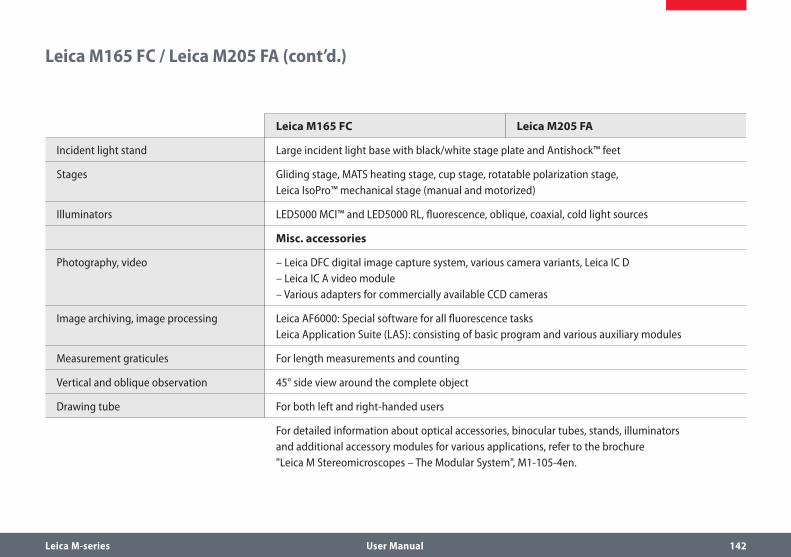
Leica M-series User Manual 142
Leica M165 FC / Leica M205 FA (cont’d.)
Leica M165 FC Leica M205 FA
Incident light stand Large incident light base with black/white stage plate and Antishock™ feet
Stages Gliding stage, MATS heating stage, cup stage, rotatable polarization stage, Leica IsoPro™ mechanical stage (manual and motorized)
Illuminators LED5000 MCI™ and LED5000 RL, fluorescence, oblique, coaxial, cold light sources
Misc. accessories
Photography, video – Leica DFC digital image capture system, various camera variants, Leica IC D – Leica IC A video module – Various adapters for commercially available CCD cameras
Image archiving, image processing Leica AF6000: Special software for all fluorescence tasks Leica Application Suite (LAS): consisting of basic program and various auxiliary modules
Measurement graticules For length measurements and counting
Vertical and oblique observation 45° side view around the complete object
Drawing tube For both left and right-handed users
For detailed information about optical accessories, binocular tubes, stands, illuminators and additional accessory modules for various applications, refer to the brochure "Leica M Stereomicroscopes – The Modular System", M1-105-4en.

Leica M-series User Manual 143
Leica EL6000 – Specifications
Dimensions (W×H×D)Width×height×depth 130 mm × 210 mm × 290 mmEnvironmental conditionsPermitted ambient temperature -20 to 85 °CPermitted relative humidity 10% to 90%,
non-condensingOperationPermitted ambient temperature 0 to 40 °CPermitted relative humidity 10% to 90%, non-condensingOperational dataApplication area Enclosed roomsAltitude for use Max. 2000 m above sea levelProtective class IType of protection IP20 (EN 60529)EMCEmitted interference EN 61326 (Class B)Immunity to interference EN 61326 Appendix AVoltage fluctuations, flicker EN 61000-3-3Harmonic currents EN 61000-3-2The instrument fulfills the requirements of EC Directive 89/336/EEC and the EMC law of September 18, 1998
Electrical safetyin accordance with EN 61010-1:2001Pollution degree 2Overvoltage category IIPower inputDesign Switched socket IEC320 C13
(EN 60320 C13)Power supply voltage 100 to 240 VAC (±10%)Power frequency 50 to 60 Hz
Fuse protection 2x T2.5 A; Breaking capacity H (manufacturer: Wickmann; Series 181)
Power consumption Max. 210 VALampType Mercury short-arc reflector
lampDesignation OSRAM HXP-R120W/45C VISPower consumption 120 WService life (manufacturer information) Average value 2000 h

Leica M-series User Manual 144
Leica EL6000 – Specifications (cont'd.)
Light outputDesign Type: Storz, longSpecial feature Self-locking if no light guide is
plugged inFanSwitch-on delay Approx. 60 s after lighting the
lampInterfaceType Remote control input for
internal shutterDesign 9-pin D-Sub socketRemote signal level– Shutter closed –8 to +0.8 V– Shutter open +2.4 to +8 V– Input current Approx. 1 mAFootswitch– Shutter closed Connection between
pin 2 and 4– Current Approx. 1.2 mAShutter frequency Max. 10 Hz
Protective functionsSafety circuit If the cover is open, all components in the instru-
ment (except for the power input and power plug) are disconnected from the power supply voltage.
Overheating protection
In the event of overheating, the lamp supply is shut off. After cooling off, the lamp power supply in the Leica EL6000 compact light source is automatically switched on again.
Protection screen If no light guide is plugged into the light output of the instrument, the light output is automatically closed off so that no light can escape.

Leica M-series User Manual 145
Leica TL ST Transmitted-light Base
Light source Halogen lamp 12V/20WQuick illuminant change YesIlluminated area 50 mmPower supply unit Input voltage 100–240 V~, frequency 50–60 Hz
energy consumption 30 W max., ambient temperature 10 – 40 °C
Connections Power plug, power switchWeight 7.4 kg Illumination typesBright field YesDark field Yes (single-sided)Oblique light NoRelief Contrast System (RC™) NoCCIC (Constant Color Intensity Control) NoInternal shutter/lamp control NoIntegrated filter holder YesCoated optics for increasing the color temperature
Yes
Matching of high num. aperture NoRemote control options NoAntiShock™ Pads YesDimensions (W×H×D) 340×430×85 mm

Leica M-series User Manual 146
Leica TL BFDF Transmitted-light Base
Light source External via cold light sourceIlluminated area 40 mmConnections Connection for cold light guide,
active f=10mm, end tube f=13mmWeight 5.8 kg Illumination typesBright field YesDark field YesOblique light NoRelief Contrast System (RC™) NoCCIC (Constant Color Intensity Control) NoInternal shutter/lamp control Yes*Integrated filter holder NoCoated optics for increasing the color temperature
No
Matching of high num. aperture Yes**Remote control options Yes***AntiShock™ Pads YesDimensions (W×H×D) 340×390×90 mm*With cold light source Leica CLS150 LS **Concave mirror *** With external light source

Leica M-series User Manual 147
Leica TL RC™ / TL RCI™
Leica TL RC™ Leica TL RCI™Light source External via cold light source Halogen lamp 12V/20WQuick illuminant change – YesIlluminated area 35 mm 35 mmPower supply unit – 100–240 V~, frequency 50–60 Hz
energy consumption 30 W max., ambient temperature 10 – 40 °C
Connections Connection for cold light guide, active f=10mm, end tube f=13mm
1×USB type A, 1×USB type B, 2×CAN-BUS
Weight 6.0 kg 7.2 kg
Illumination typesBright field/dark field Yes/yes Yes/yesOblique light/Relief Contrast System (RC™) Yes/yes Yes/yesCCIC (Constant Color Intensity Control) No YesInternal shutter/lamp control Yes** YesIntegrated filter holder Yes YesCoated optics for increasing the color temperature Yes YesMatching of high num. aperture Yes*** Yes***Remote control options Yes**** YesAntiShock™ Pads Yes YesDimensions of base (W×H×D) 340×390×95 mm 340×440×95 mm*Single-sided **With cold light source Leica CLS150 LS ***Concave mirror ****With external light source
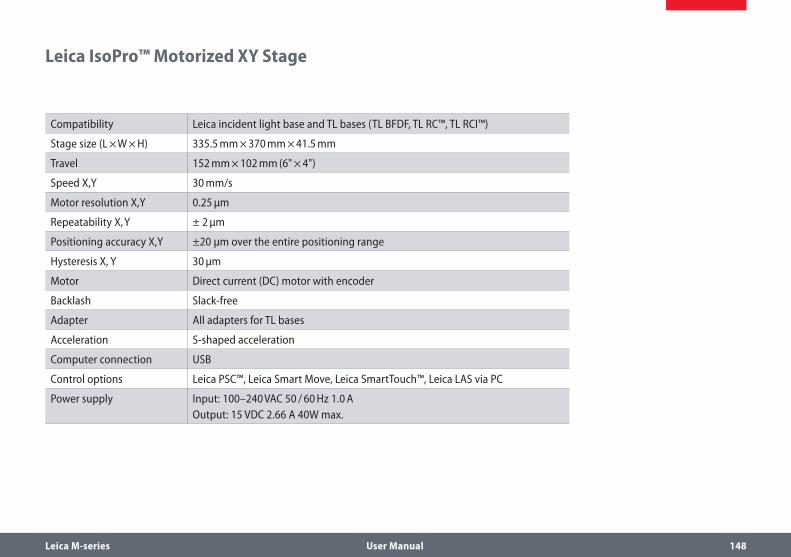
Leica M-series User Manual 148
Leica IsoPro™ Motorized XY Stage
Compatibility Leica incident light base and TL bases (TL BFDF, TL RC™, TL RCI™)
Stage size (L × W × H) 335.5 mm × 370 mm × 41.5 mm
Travel 152 mm × 102 mm (6" × 4")
Speed X,Y 30 mm/s
Motor resolution X,Y 0.25 µm
Repeatability X, Y ± 2 µm
Positioning accuracy X,Y ±20 µm over the entire positioning range
Hysteresis X, Y 30 µm
Motor Direct current (DC) motor with encoder
Backlash Slack-free
Adapter All adapters for TL bases
Acceleration S-shaped acceleration
Computer connection USB
Control options Leica PSC™, Leica Smart Move, Leica SmartTouch™, Leica LAS via PC
Power supply Input: 100–240 VAC 50 / 60 Hz 1.0 AOutput: 15 VDC 2.66 A 40W max.

Leica M-series User Manual 149
Appendix

Leica M-series User Manual 150
Calculating the Total Magnification and Field of View Diameter
Parameter
MO Magnification of the objective
ME Magnification of the eyepiece
z Magnification of the changer position
q Tube factor, e.g. 1.5× for coaxial incident light, 1.6× for 45° ErgoTube™
r Factor 1.25x if the planachromatic and planapochromatic objectives of the MZ125/MZ16 are used on the MS5, MZ6, MZ75 or MZ95
NFOV Field number of the eyepiece. Field numbers are printed on the eyepieces: 10× = 21, 16× = 14, 25× = 9.5, 40× = 6.
Example
MO 1× objective
ME 25×/9.5 eyepiece
z Zoom position 4
q Coaxial reflected light 1.5×, tube factor
r Factor 1.25×
Calculation example: Magnification in the binocular tube:
MTOT VIS = MO × ME × z × q × r or
1 × 25 × 4 × 1.5 × 1.25 = 187.5×
Calculation example: Field of view diameter in the specimen
∅ OF:NFOV
MO × z ×q ×r

Leica M-series User Manual 151
Care, Maintenance, Contact Persons
We hope you enjoy using your high-perfor-mance microscope. Leica microscopes are renowned for their robustness and long service life. Observing the following care and clean-ing tips will ensure that even after years and decades, your Leica microscope will continue to work as well as it did on the very first day.
Warranty benefitsThe warranty covers all faults in materials and manufacture. It does not, however, cover damage resulting from careless or improper handling.
Contact addressHowever, if your instrument should no longer function properly, contact your technician, your Leica representative or Leica Microsystems (Switzerland) AG, CH-9435 Heerbrugg.
E-mail contact:[email protected]
CareProtect your microscope from moisture, ρ
fumes and acids and from alkaline, caustic and corrosive materials and keep chemicals away from the instruments.
Plugs, optical systems and mechanical parts ρ
must not be disassembled or replaced, unless doing so is specifically permitted and described in this manual.
Protect your microscope from oil and ρ
grease.
Do not grease guide surfaces or mechani- ρ
cal parts.

Leica M-series User Manual 152
Care, Maintenance, Contact Persons (cont'd.)
Protection from dirtDust and dirt will affect the quality of your results.
Put a dust cover over the microscope when ρ
it will not be used for a long time.
Use dust caps to protect tube openings, ρ
tubes without eyepieces, and eyepieces.
Keep accessories in a dust-free place when ρ
not in use.
Cleaning polymer componentsSome components are made of polymer or are polymer-coated. They are, therefore, pleasant and convenient to handle. The use of unsuitable cleaning agents and techniques can damage polymers.
Permitted measuresClean the microscope (or parts of it) using ρ
warm soapy water, then wipe using distilled water.
For stubborn dirt, you can also use ethanol ρ
(industrial alcohol) or isopropanol. When doing so, follow the corresponding safety instructions.
Remove dust with a pneumatic rubber bulb ρ
or with a soft brush.
Clean objectives and eyepieces with ρ
special optic cleaning cloths and with pure alcohol.