Lehigh Series LSS® 3000 PSI High Pressure · Lehigh Series LSS® 3000 PSI High Pressure Hydraulic...
19
Transcript of Lehigh Series LSS® 3000 PSI High Pressure · Lehigh Series LSS® 3000 PSI High Pressure Hydraulic...
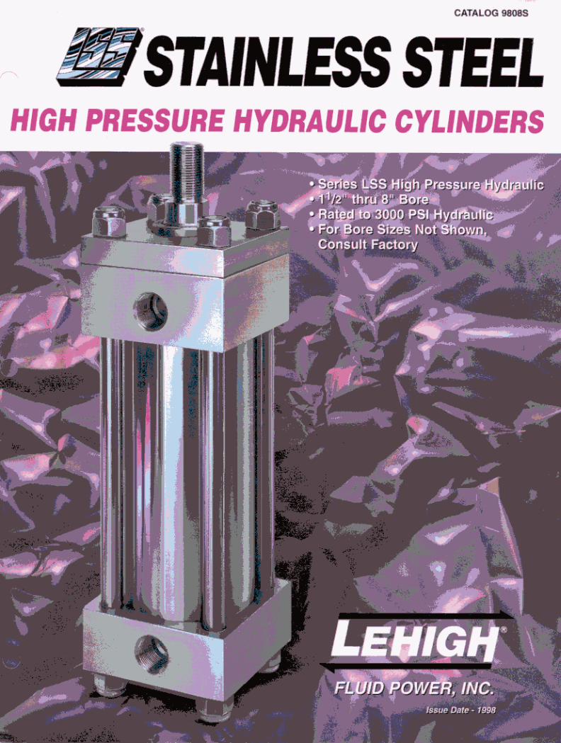

Lehigh Series LSS® 3000 PSI High Pressure Hydraulic Stainless Steel Cylinders…built to survive where other cylinders fail. If you can’t find anyone with a 3000psi rated stainless steel high pressure hydraulic cylinder in their catalogs… your search is over. The LSS® Series High Pressure Hydraulic Stainless Steel Cylinders are designed to achieve long life and consistent performance in the worst conditions. Submerged Operation? Chemicals? Clean Room Operation? Food or Beverage Equipment? FDA or USDA Equipment? NO PROBLEM… Lehigh is the answer. That’s because we have the answers to your questions… • My aluminum cylinders fail constantly from
corrosion, can you help? • We want to operate a cylinder on strained creek
water, is that OK? • We want to operate our cylinders on partially treated
sewage water. • Can I run my cylinder on tap water? • My plated cylinders don’t last, why is that? • My chrome bore steel tubing keeps rusting because I
am running on water-glycol fluid, what do you recommend?
• Our cylinders get ruined by constant wash-downs, what are my options?
Tough applications like these are a way of life in some industries and that’s why Lehigh’s standard products like the LSS® Series Cylinders were designed. They provide long-term solutions to many everyday problems and are an excellent platform to build specialty products. The best feature of a Lehigh stainless cylinder is long-term savings in both reduced downtime and maintenance. Let Lehigh’s sales and engineering departments help you select the best product for your application. Call us today and solve your problem… This information should be used as a guide for your consideration, investigation, and verification. This information does not constitute a warranty or representation and we assume no legal responsibility or obligation with respect thereto, and the use of which such information may be put. As product improvement is a continuous process, specifications are subject to change without notice.
© Copyright 1998 Lehigh Fluid Power, Inc.

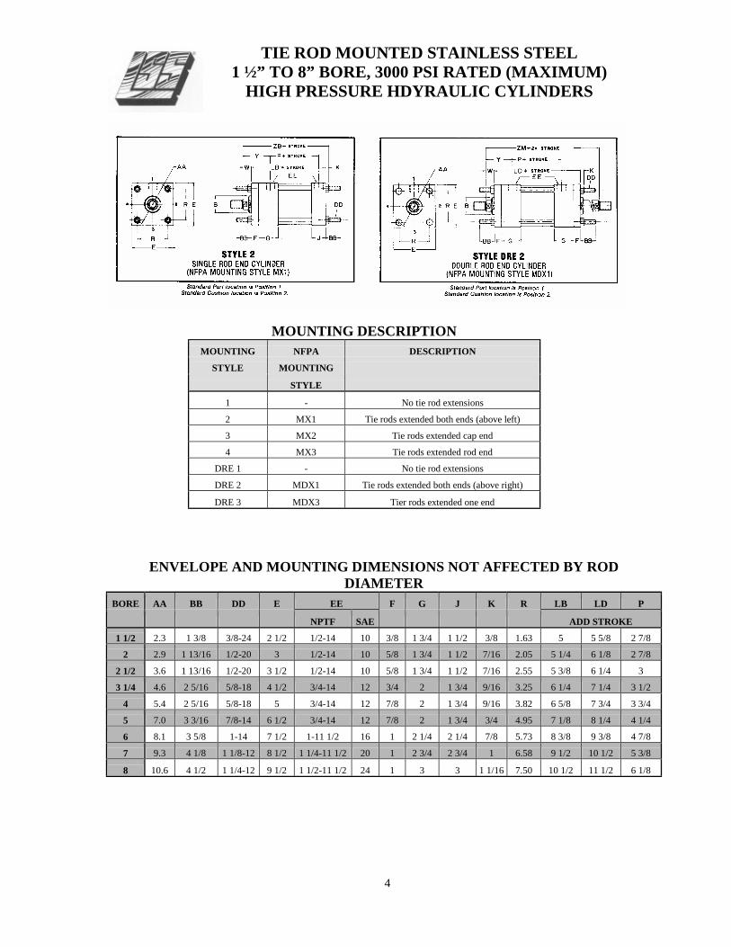
TIE ROD MOUNTED STAINLESS STEEL 1 ½” TO 8” BORE, 3000 PSI RATED (MAXIMUM)
HIGH PRESSURE HDYRAULIC CYLINDERS
MOUNTING DESCRIPTION MOUNTING NFPA DESCRIPTION
STYLE MOUNTING
STYLE
1 - No tie rod extensions
2 MX1 Tie rods extended both ends (above left) 3 MX2 Tie rods extended cap end
4 MX3 Tie rods extended rod end DRE 1 - No tie rod extensions
DRE 2 MDX1 Tie rods extended both ends (above right)
DRE 3 MDX3 Tier rods extended one end
ENVELOPE AND MOUNTING DIMENSIONS NOT AFFECTED BY ROD
DIAMETER BORE AA BB DD E EE F G J K R LB LD P
NPTF SAE ADD STROKE 1 1/2 2.3 1 3/8 3/8-24 2 1/2 1/2-14 10 3/8 1 3/4 1 1/2 3/8 1.63 5 5 5/8 2 7/8
2 2.9 1 13/16 1/2-20 3 1/2-14 10 5/8 1 3/4 1 1/2 7/16 2.05 5 1/4 6 1/8 2 7/8
2 1/2 3.6 1 13/16 1/2-20 3 1/2 1/2-14 10 5/8 1 3/4 1 1/2 7/16 2.55 5 3/8 6 1/4 3
3 1/4 4.6 2 5/16 5/8-18 4 1/2 3/4-14 12 3/4 2 1 3/4 9/16 3.25 6 1/4 7 1/4 3 1/2
4 5.4 2 5/16 5/8-18 5 3/4-14 12 7/8 2 1 3/4 9/16 3.82 6 5/8 7 3/4 3 3/4
5 7.0 3 3/16 7/8-14 6 1/2 3/4-14 12 7/8 2 1 3/4 3/4 4.95 7 1/8 8 1/4 4 1/4
6 8.1 3 5/8 1-14 7 1/2 1-11 1/2 16 1 2 1/4 2 1/4 7/8 5.73 8 3/8 9 3/8 4 7/8
7 9.3 4 1/8 1 1/8-12 8 1/2 1 1/4-11 1/2 20 1 2 3/4 2 3/4 1 6.58 9 1/2 10 1/2 5 3/8
8 10.6 4 1/2 1 1/4-12 9 1/2 1 1/2-11 1/2 24 1 3 3 1 1/16 7.50 10 1/2 11 1/2 6 1/8
4

DIMENSIONS AFFECTED BY ROD DIAMETER
ROD THREAD SIZE ROD EXTENSIONS & PILOT DIMENSIONS DIA.
BORE MM KK CC A B C D LA NA V W Y ZB ZM STD. +.000 ADD ADD 2X -.002 STROKE STROKE
1 1/2 5/8 7/16-20 1/2-20 3/4 1.124 3/8 1/2 1 3/8 9/16 1/4 5/8 2 6 6 7/8
1 3/4-16 7/8-14 1 1/8 1.499 1/2 7/8 2 1/8 15/16 1/2 1 2 3/8 6 3/8 7 5/8
2 1 3/4-16 7/8-14 1 1/8 1.499 1/2 7/8 1 7/8 15/16 1/4 3/4 2 3/8 6 7/16 7 5/8
1 3/8* 1-14 1 1/4-12 1 5/8 1.999 5/8 1 1/8 2 5/8 1 5/16 3/8 1 2 5/8 6 11/16 8 1/8
1 3/4-16 7/8-14 1 1/8 1.499 1/2 7/8 1 7/8 15/16 1/4 3/4 2 3/8 6 9/16 7 3/4
2 1/2 1 3/8 1-14 1 1/4-12 1 5/8 1.999 5/8 1 1/8 2 5/8 1 5/16 3/8 1 2 5/8 6 13/16 8 1/4
1 3/4 1 1/4-12 1 1/2-12 2 2.374 3/4 1 1/2 3 1/4 1 11/16 1/2 1 1/4 2 7/8 7 1/16 8 3/4
1 3/8 1-14 1 1/4-12 1 5/8 1.999 5/8 1 1/8 2 1/2 1 5/16 1/4 7/8 2 3/4 7 11/16 9
3 1/4 1 3/4 1 1/4-12 1 1/2-12 2 2.374 3/4 1 1/2 3 1/8 1 11/16 3/8 1 1/8 3 7 15/16 9 1/2
2 1 1/2-12 1 3/4-12 2 1/4 2.624 7/8 1 11/16 3 1/2 1 15/16 3/8 1 1/4 3 1/8 8 1/16 9 3/4
1 3/4 1 1/4-12 1 1/2-12 2 2.374 3/4 1 1/2 3 1 11/16 1/4 1 3 8 3/16 9 3/4
4 2 1 1/2-12 1 3/4-12 2 1/4 2.624 7/8 1 11/16 3 3/8 1 15/16 1/4 1 1/8 3 1/8 8 5/16 10
2 1/2 1 7/8-12 2 1/4-12 3 3.124 1 2 1/16 4 3/8 2 7/16 3/8 1 3/8 3 3/8 8 9/16 10 1/2
2 1 1/2-12 1 3/4-12 2 1/4 2.624 7/8 1 11/16 3 3/8 1 15/16 1/4 1 1/8 3 1/8 9 10 1/2
5 2 1/2 1 7/8-12 2 1/4-12 3 3.124 1 2 1/16 4 3/8 2 7/16 3/8 1 3/8 3 3/8 9 1/4 11
3 2 1/4-12 2 3/4-12 3 1/2 3.749 1 2 5/8 4 7/8 2 15/16 3/8 1 3/8 3 3/8 9 1/4 11
3 1/2 2 1/2-12 3 1/4-12 3 1/2 4.249 1 3 4 7/8 3 7/16 3/8 1 3/8 3 3/8 9 1/4 11
2 1/2 1 7/8-12 2 1/4-12 3 3.124 1 2 1/16 4 1/4 2 7/16 1/4 1 1/4 3 1/2 10 1/2 11 7/8
6 3 2 1/4-12 2 3/4-12 3 1/2 3.749 1 2 5/8 4 3/4 2 15/16 1/4 1 1/4 3 1/2 10 1/2 11 7/8
3 1/2 2 1/2-12 3 1/4-12 3 1/2 4.249 1 3 4 3/4 3 7/16 1/4 1 1/4 3 1/2 10 1/2 11 7/8
4 3-12 3 3/4-12 4 4.749 1 3 3/8 5 1/4 3 15/16 1/4 1 1/4 3 1/2 10 1/2 11 7/8
3 2 1/4-12 2 3/4-12 3 1/2 3.749 1 2 5/8 4 3/4 2 7/8 1/4 1 1/4 3 13/16 11 3/4 13
7 3 1/2 2 1/2-12 3 1/4-12 3 1/2 4.249 1 3 4 3/4 3 3/8 1/4 1 1/4 3 13/16 11 3/4 13
4 3-12 3 3/4-12 4 4.749 1 3 3/8 5 1/4 3 7/8 1/4 1 1/4 3 13/16 11 3/4 13
5 3 1/2-12 4 3/4-12 5 5.749 1 4 1/4 6 1/4 4 7/8 1/4 1 1/4 3 13/16 11 3/4 13
3 1/2 2 1/2-12 3 1/4-12 3 1/2 4.249 1 3 4 3/4 3 3/8 1/4 1 1/4 3 15/16 12 13/16 14
8 4 3-12 3 3/4-12 4 4.749 1 3 3/8 5 1/4 3 7/8 1/4 1 1/4 3 15/16 12 13/16 14
5 3 1/2-12 4 3/4-12 5 5.749 1 4 1/4 6 1/4 4 7/8 1/4 1 1/4 3 15/16 12 13/16 14
5 1/2 4-12 5 1/4-12 5 1/2 6.249 1 4 5/8 6 3/4 5 3/8 1/4 1 1/4 3 15/16 12 13/16 14
5
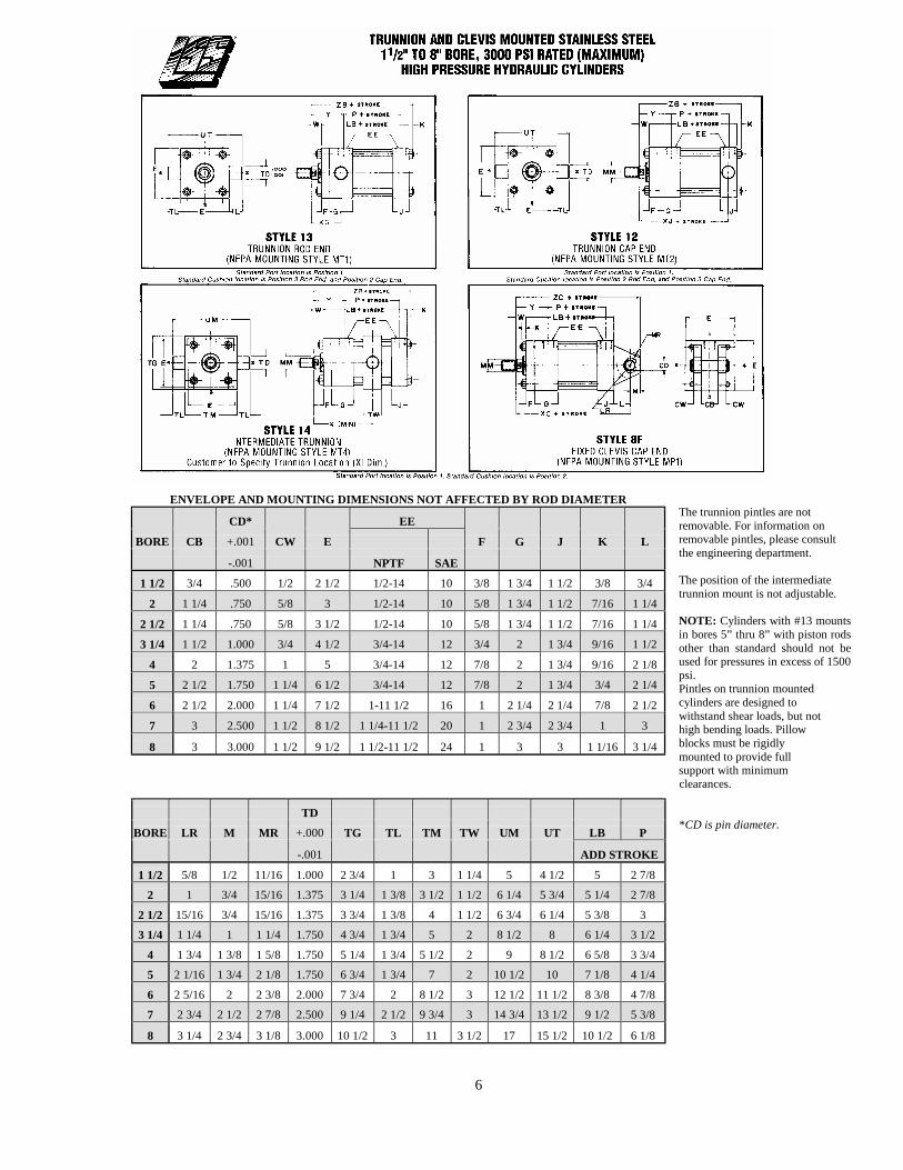
The trunnion pintles are not removable. For information on removable pintles, please consult the engineering department. The position of the intermediate trunnion mount is not adjustable. NOTE: Cylinders with #13 mounts in bores 5” thru 8” with piston rods other than standard should not be used for pressures in excess of 1500 psi. Pintles on trunnion mounted cylinders are designed to withstand shear loads, but not high bending loads. Pillow blocks must be rigidly mounted to provide full support with minimum clearances. *CD is pin diameter.
6
ENVELOPE AND MOUNTING DIMENSIONS NOT AFFECTED BY ROD DIAMETER
CD* EE BORE CB +.001 CW E F G J K L
-.001 NPTF SAE 1 1/2 3/4 .500 1/2 2 1/2 1/2-14 10 3/8 1 3/4 1 1/2 3/8 3/4
2 1 1/4 .750 5/8 3 1/2-14 10 5/8 1 3/4 1 1/2 7/16 1 1/4
2 1/2 1 1/4 .750 5/8 3 1/2 1/2-14 10 5/8 1 3/4 1 1/2 7/16 1 1/4
3 1/4 1 1/2 1.000 3/4 4 1/2 3/4-14 12 3/4 2 1 3/4 9/16 1 1/2
4 2 1.375 1 5 3/4-14 12 7/8 2 1 3/4 9/16 2 1/8
5 2 1/2 1.750 1 1/4 6 1/2 3/4-14 12 7/8 2 1 3/4 3/4 2 1/4
6 2 1/2 2.000 1 1/4 7 1/2 1-11 1/2 16 1 2 1/4 2 1/4 7/8 2 1/2
7 3 2.500 1 1/2 8 1/2 1 1/4-11 1/2 20 1 2 3/4 2 3/4 1 3
8 3 3.000 1 1/2 9 1/2 1 1/2-11 1/2 24 1 3 3 1 1/16 3 1/4
TD BORE LR M MR +.000 TG TL TM TW UM UT LB P
-.001 ADD STROKE 1 1/2 5/8 1/2 11/16 1.000 2 3/4 1 3 1 1/4 5 4 1/2 5 2 7/8
2 1 3/4 15/16 1.375 3 1/4 1 3/8 3 1/2 1 1/2 6 1/4 5 3/4 5 1/4 2 7/8 2 1/2 15/16 3/4 15/16 1.375 3 3/4 1 3/8 4 1 1/2 6 3/4 6 1/4 5 3/8 3 3 1/4 1 1/4 1 1 1/4 1.750 4 3/4 1 3/4 5 2 8 1/2 8 6 1/4 3 1/2
4 1 3/4 1 3/8 1 5/8 1.750 5 1/4 1 3/4 5 1/2 2 9 8 1/2 6 5/8 3 3/4 5 2 1/16 1 3/4 2 1/8 1.750 6 3/4 1 3/4 7 2 10 1/2 10 7 1/8 4 1/4 6 2 5/16 2 2 3/8 2.000 7 3/4 2 8 1/2 3 12 1/2 11 1/2 8 3/8 4 7/8 7 2 3/4 2 1/2 2 7/8 2.500 9 1/4 2 1/2 9 3/4 3 14 3/4 13 1/2 9 1/2 5 3/8
8 3 1/4 2 3/4 3 1/8 3.000 10 1/2 3 11 3 1/2 17 15 1/2 10 1/2 6 1/8

DIMENSIONS AFFECTED BY ROD DIAMETER
ROD THREAD SIZE ROD EXTENSIONS & PILOT DIMENSIONS ENVELOPE DIMENSIONS BORE DIA. KK CC A B C D LA NA V W Y XG XI XC XJ ZB ZC
MM STD. +.000/ MIN.
-.002 ADD STROKE 1 1/2 5/8 7/16-20 1/2-20 3/4 1.124 3/8 1/2 1 3/8 9/16 1/4 5/8 2 1 7/8 3 3/8 6 3/8 4 7/8 6 6 7/8
1* 3/4-16 7/8-14 1 1/8 1.499 1/2 7/8 2 1/8 15/16 1/2 1 2 3/8 2 1/4 3 3/4 6 3/4 5 1/4 6 3/8 7 1/4
2 1 3/4-16 7/8-14 1 1/8 1.499 1/2 7/8 1 7/8 15/16 1/4 3/4 2 3/8 2 1/4 3 7/8 7 1/4 5 1/4 6 7/16 8
1 3/8* 1-14 1 1/4-12 1 5/8 1.499 5/8 1 1/8 2 5/8 1 5/16 3/8 1 2 5/8 2 1/2 4 1/8 7 1/2 5 1/2 6 11/16 8 1/4
1 3/4-16 7/8-14 1 1/8 1.499 1/2 7/8 1 7/8 15/16 1/4 3/4 2 3/8 2 1/4 3 7/8 7 3/8 5 3/8 6 9/16 8 1/8
2 1/2 1 3/8 1-14 1 1/4-12 1 5/8 1.999 5/8 1 1/8 2 5/8 1 5/16 3/8 1 2 5/8 2 1/2 4 1/8 7 5/8 5 5/8 6 13/16 8 3/8
1 3/4* 1 1/4-12 1 1/2-12 2 2.374 3/4 1 1/2 3 1/4 1 11/16 1/2 1 1/4 2 7/8 2 3/4 4 3/8 7 7/8 5 7/8 7 1/16 8 5/8
1 3/8 1-14 1 1/4-12 1 5/8 1.999 5/8 1 1/8 2 1/2 1 5/16 1/4 7/8 2 3/4 2 5/8 4 5/8 8 5/8 6 1/4 7 11/16 9 5/8
3 1/4 1 3/4 1 1/4-12 1 1/2-12 2 2.374 3/4 1 1/2 3 1/8 1 11/16 3/8 1 1/8 3 2 7/8 4 7/8 8 7/8 6 1/2 7 15/16 9 7/8
2 1 1/2-12 1 3/4-12 2 1/4 2.624 7/8 1 11/16 3 1/2 1 15/16 3/8 1 1/4 3 1/8 3 5 9 6 5/8 8 1/16 10
1 3/4 1 1/4-12 1 1/2-12 2 2.374 3/4 1 1/2 3 1 11/16 1/4 1 3 2 7/8 4 7/8 9 3/4 6 3/4 8 3/16 11 1/8
4 2 1 1/2-12 1 3/4-12 2 1/4 2.624 7/8 1 11/16 3 3/8 1 15/16 1/4 1 1/8 3 1/8 3 5 9 7/8 6 7/8 8 5/16 11 1/4
2 1/2 1 7/8-12 2 1/4-12 3 3.124 1 2 1/16 4 3/8 2 7/16 3/8 1 3/8 3 3/8 3 1/4 5 1/4 10 1/8 7 1/8 8 9/16 11 1/2
2 1 1/2-12 1 3/4-12 2 1/4 2.624 7/8 1 11/16 3 3/8 1 15/16 1/4 1 1/8 3 1/8 3 5 10 1/2 7 3/8 9 12 1/4
5 2 1/2 1 7/8-12 2 1/4-12 3 3.124 1 2 1/16 4 3/8 2 7/16 3/8 1 3/8 3 3/8 3 1/4 5 1/4 10 3/4 7 5/8 9 1/4 12 1/2
3 2 1/4-12 2 3/4-12 3 1/2 3.749 1 2 5/8 4 7/8 2 15/16 3/8 1 3/8 3 3/8 3 1/4 5 1/4 10 3/4 7 5/8 9 1/4 12 1/2
3 1/2 2 1/2-12 3 1/4-12 3 1/2 4.249 1 3 4 7/8 3 7/16 3/8 1 3/8 3 3/8 3 1/4 5 1/4 10 3/4 7 5/8 9 1/4 12 1/2
2 1/2 1 7/8-12 2 1/4-12 3 3.124 1 2 1/16 4 1/4 2 7/16 1/4 1 1/4 3 1/2 3 3/8 6 12 1/8 8 3/8 10 1/2 14 1/8
6 3 2 1/4-12 2 3/4-12 3 1/2 3.749 1 2 5/8 4 3/4 2 15/16 1/4 1 1/4 3 1/2 3 3/8 6 12 1/8 8 3/8 10 1/2 14 1/8
3 1/2 2 1/2-12 3 1/4-12 3 1/2 4.249 1 3 4 3/4 3 7/16 1/4 1 1/4 3 1/2 3 3/8 6 12 1/8 8 3/8 10 1/2 14 1/8
4 3-12 3 3/4-12 4 4.749 1 3 3/8 5 1/4 3 15/16 1/4 1 1/4 3 1/2 3 3/8 6 12 1/8 8 3/8 10 1/2 14 1/8
3 2 1/4-12 2 3/4-12 3 1/2 3.749 1 2 5/8 4 3/4 2 7/8 1/4 1 1/4 3 13/16 3 5/8 6 1/2 13 3/4 9 3/8 11 3/4 16 1/4
7 3 1/2 2 1/2-12 3 1/4-12 3 1/2 4.249 1 3 4 3/4 3 3/8 1/4 1 1/4 3 13/16 3 5/8 6 1/2 13 3/4 9 3/8 11 3/4 16 1/4
4 3-12 3 3/4-12 4 4.749 1 3 3/8 5 1/4 3 7/8 1/4 1 1/4 3 13/16 3 5/8 6 1/2 13 3/4 9 3/8 11 3/4 16 1/4
5 3 1/2-12 4 3/4-12 5 5.749 1 4 1/4 6 1/4 4 7/8 1/4 1 1/4 3 13/16 3 5/8 6 1/2 13 3/4 9 3/8 11 3/4 16 1/4
3 1/2 2 1/2-12 3 1/4-12 3 1/2 4.249 1 3 4 3/4 3 3/8 1/4 1 1/4 3 15/16 3 3/4 7 15 10 1/4 12 13/16 17 3/4
8 4 3-12 3 3/4-12 4 4.749 1 3 3/8 5 1/4 3 7/8 1/4 1 1/4 3 15/16 3 3/4 7 15 10 1/4 12 13/16 17 3/4
5 3 1/2-12 4 3/4-12 5 5.749 1 4 1/4 6 1/4 4 7/8 1/4 1 1/4 3 15/16 3 3/4 7 15 10 1/4 12 13/16 17 3/4
5 1/2 4-12 5 1/4-12 5 1/2 6.249 1 4 5/8 6 3/4 5 3/8 1/4 1 1/4 3 15/16 3 3/4 7 15 10 1/4 12 13/16 17 3/4 *Rod end cushions available only as non-adjustable type- Consult Lehigh
7

ENVELOPE AND MOUNTING DIMENSIONS NOT AFFECTED BY ROD DIAMETER
BORE E EE F FB G J K R TF UF LB P
NPTF SAE ADD STROKE 1 1/2 2 1/2 1/2-14 10 3/8 7/16 1 3/4 1 1/2 3/8 1.63 3 7/16 4 1/4 5 2 7/8
2 3 1/2-14 10 5/8 9/16 1 3/4 1 1/2 7/16 2.05 4 1/8 5 1/8 5 1/4 2 7/8
2 1/2 3 1/2 1/2-14 10 5/8 9/16 1 3/4 1 1/2 7/16 2.55 4 5/8 5 5/8 5 3/8 3
3 1/4 4 1/2 3/4-14 12 3/4 11/16 2 1 3/4 9/16 3.25 5 7/8 7 1/8 6 1/4 3 1/2
4 5 3/4-14 12 7/8 11/16 2 1 3/4 9/16 3.82 6 3/8 7 5/8 6 5/8 3 3/4
5 6 1/2 3/4-14 12 7/8 15/16 2 1 3/4 3/4 4.95 8 3/16 9 3/4 7 1/8 4 1/4
6 7 1/2 1-11 1/2 16 1 1 1/16 2 1/4 2 1/4 7/8 5.73 9 7/16 11 1/4 8 3/8 4 7/8
7 8 1/2 1 1/4-11 1/2 20 1 1 3/16 2 3/4 2 3/4 1 6.58 10 5/8 12 5/8 9 1/2 5 3/8
8 9 1/2 1 1/2-11 1/2 24 1 1 5/16 3 3 1 1/16 7.50 11 13/16 14 10 1/2 6 1/8
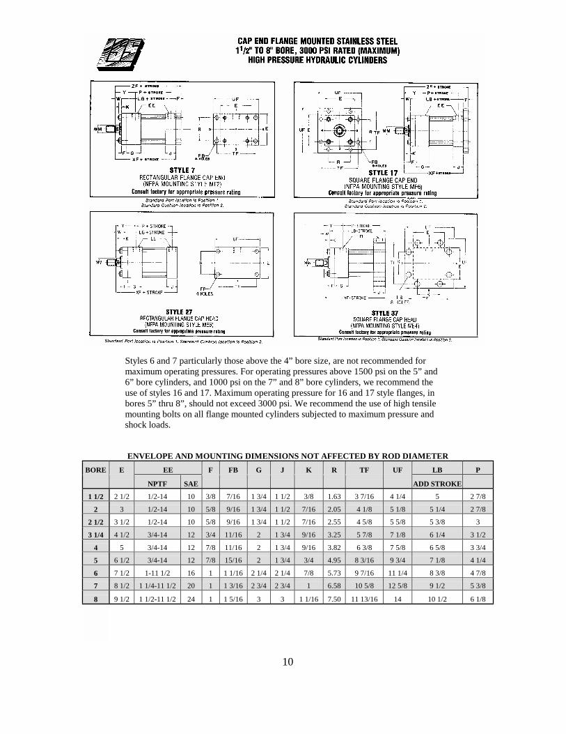
Styles 6 and 7 particularly those above the 4” bore size, are not recommended for maximum operating pressures. For operating pressures above 1500 psi on the 5” and 6” bore cylinders, and 1000 psi on the 7” and 8” bore cylinders, we recommend the use of styles 16 and 17. Maximum operating pressure for 16 and 17 style flanges, in bores 5” thru 8”, should not exceed 3000 psi. We recommend the use of high tensile mounting bolts on all flange mounted cylinders subjected to maximum pressures and shock loads.
ROD MOUNT PORT MAX.OPER.
BORE DIA. STYLE POSITION PRESSURE-PSI 5 3 1/2 26 1 or 3 2500
6 3 1/2 26 1 or 3 2500
4 26 1 or 3 1500
7 4 26 1 or 3 2500
5 26 1 or 3 1500
8 5 26 1 or 3 2500
5 1/2 26 1 or 3 1500
8

DIMENSIONS AFFECTED BY ROD DIAMETER
ROD THREAD SIZE ROD EXTENSIONS & PILOT DIMENSIONS ENVELOPE DIMENSIONS BORE DIA. KK CC A B C D LA NA V RD W WF Y ZB
MM STD. +.000/-.002 ADD STROKE 1 1/2 5/8 7/16-20 1/2-20 3/4 1.124 3/8 1/2 1 3/8 9/16 1/4 2.38 5/8 1 2 6
1* 3/4-16 7/8-14 1 1/8 1.499 1/2 7/8 2 1/8 15/16 1/2 2.5 SQ 1 1 3/8 2 3/8 6 3/8
2 1 3/4-16 7/8-14 1 1/8 1.499 1/2 7/8 1 7/8 15/16 1/4 2.87 3/4 1 3/8 2 3/8 6 7/16
1 3/8* 1-14 1 1/4-12 1 5/8 1.499 5/8 1 1/8 2 5/8 1 5/16 3/8 3.0 SQ 1 1 5/8 2 5/8 6 11/16
1 3/4-16 7/8-14 1 1/8 1.499 1/2 7/8 1 7/8 15/16 1/4 2.87 3/4 1 3/8 2 3/8 6 9/16
2 1/2 1 3/8 1-14 1 1/4-12 1 5/8 1.999 5/8 1 1/8 2 5/8 1 5/16 3/8 3.37 1 1 5/8 2 5/8 6 13/16
1 3/4* 1 1/4-12 1 1/2-12 2 2.374 3/4 1 1/2 3 1/4 1 11/16 1/2 3.5 SQ 1 1/4 1 7/8 2 7/8 7 1/16
1 3/8 1-14 1 1/4-12 1 5/8 1.999 5/8 1 1/8 2 1/2 1 5/16 1/4 3.37 7/8 1 5/8 2 3/4 7 11/16
3 1/4 1 3/4 1 1/4-12 1 1/2-12 2 2.374 3/4 1 1/2 3 1/8 1 11/16 3/8 4.00 1 1/8 1 7/8 3 7 15/16
2 1 1/2-12 1 3/4-12 2 1/4 2.624 7/8 1 11/16 3 1/2 1 15/16 3/8 4.25 1 1/4 2 3 1/8 8 1/16
1 3/4 1 1/4-12 1 1/2-12 2 2.374 3/4 1 1/2 3 1 11/16 1/4 4.00 1 1 7/8 3 8 3/16
4 2 1 1/2-12 1 3/4-12 2 1/4 2.624 7/8 1 11/16 3 3/8 1 15/16 1/4 4.25 1 1/8 2 3 1/8 8 5/16
2 1/2 1 7/8-12 2 1/4-12 3 3.124 1 2 1/16 4 3/8 2 7/16 3/8 4.50 1 3/8 2 1/4 3 3/8 8 9/16
2 1 1/2-12 1 3/4-12 2 1/4 2.624 7/8 1 11/16 3 3/8 1 15/16 1/4 4.25 1 1/8 2 3 1/8 9
5 2 1/2 1 7/8-12 2 1/4-12 3 3.124 1 2 1/16 4 3/8 2 7/16 3/8 4.50 1 3/8 2 1/4 3 3/8 9 1/4
3 2 1/4-12 2 3/4-12 3 1/2 3.749 1 2 5/8 4 7/8 2 15/16 3/8 5.50 1 3/8 2 1/4 3 3/8 9 1/4
3 1/2 2 1/2-12 3 1/4-12 3 1/2 4.249 1 3 4 7/8 3 7/16 3/8 5.75 1 3/8 2 1/4 3 3/8 9 1/4
2 1/2 1 7/8-12 2 1/4-12 3 3.124 1 2 1/16 4 1/4 2 7/16 1/4 4.50 1 1/4 2 1/4 3 1/2 10 1/2
6 3 2 1/4-12 2 3/4-12 3 1/2 3.749 1 2 5/8 4 3/4 2 15/16 1/4 5.50 1 1/4 2 1/4 3 1/2 10 1/2
3 1/2 2 1/2-12 3 1/4-12 3 1/2 4.249 1 3 4 3/4 3 7/16 1/4 5.75 1 1/4 2 1/4 3 1/2 10 1/2
4 3-12 3 3/4-12 4 4.749 1 3 3/8 5 1/4 3 15/16 1/4 6.50 1 1/4 2 1/4 3 1/2 10 1/2
3 2 1/4-12 2 3/4-12 3 1/2 3.749 1 2 5/8 4 3/4 2 7/8 1/4 5.50 1 1/4 2 1/4 3 13/16 11 3/4
7 3 1/2 2 1/2-12 3 1/4-12 3 1/2 4.249 1 3 4 3/4 3 3/8 1/4 5.75 1 1/4 2 1/4 3 13/16 11 3/4
4 3-12 3 3/4-12 4 4.749 1 3 3/8 5 1/4 3 7/8 1/4 6.50 1 1/4 2 1/4 3 13/16 11 3/4
5 3 1/2-12 4 3/4-12 5 5.749 1 4 1/4 6 1/4 4 7/8 1/4 7.50 1 1/4 2 1/4 3 13/16 11 3/4
3 1/2 2 1/2-12 3 1/4-12 3 1/2 4.249 1 3 4 3/4 3 3/8 1/4 5.75 1 1/4 2 1/4 3 15/16 12 13/16
8 4 3-12 3 3/4-12 4 4.749 1 3 3/8 5 1/4 3 7/8 1/4 6.50 1 1/4 2 1/4 3 15/16 12 13/16
5 3 1/2-12 4 3/4-12 5 5.749 1 4 1/4 6 1/4 4 7/8 1/4 7.50 1 1/4 2 1/4 3 15/16 12 13/16
5 1/2 4-12 5 1/4-12 5 1/2 6.249 1 4 5/8 6 3/4 5 3/8 1/4 8.50 1 1/4 2 1/4 3 15/16 12 13/16 *Rod end cushions available only as non-adjustable type- Consult Lehigh
9
Styles 6 and 7 particularly those above the 4” bore size, are not recommended for maximum operating pressures. For operating pressures above 1500 psi on the 5” and 6” bore cylinders, and 1000 psi on the 7” and 8” bore cylinders, we recommend the use of styles 16 and 17. Maximum operating pressure for 16 and 17 style flanges, in bores 5” thru 8”, should not exceed 3000 psi. We recommend the use of high tensile mounting bolts on all flange mounted cylinders subjected to maximum pressure and shock loads.
ENVELOPE AND MOUNTING DIMENSIONS NOT AFFECTED BY ROD DIAMETER BORE E EE F FB G J K R TF UF LB P
NPTF SAE ADD STROKE 1 1/2 2 1/2 1/2-14 10 3/8 7/16 1 3/4 1 1/2 3/8 1.63 3 7/16 4 1/4 5 2 7/8
2 3 1/2-14 10 5/8 9/16 1 3/4 1 1/2 7/16 2.05 4 1/8 5 1/8 5 1/4 2 7/8
2 1/2 3 1/2 1/2-14 10 5/8 9/16 1 3/4 1 1/2 7/16 2.55 4 5/8 5 5/8 5 3/8 3
3 1/4 4 1/2 3/4-14 12 3/4 11/16 2 1 3/4 9/16 3.25 5 7/8 7 1/8 6 1/4 3 1/2
4 5 3/4-14 12 7/8 11/16 2 1 3/4 9/16 3.82 6 3/8 7 5/8 6 5/8 3 3/4
5 6 1/2 3/4-14 12 7/8 15/16 2 1 3/4 3/4 4.95 8 3/16 9 3/4 7 1/8 4 1/4
6 7 1/2 1-11 1/2 16 1 1 1/16 2 1/4 2 1/4 7/8 5.73 9 7/16 11 1/4 8 3/8 4 7/8
7 8 1/2 1 1/4-11 1/2 20 1 1 3/16 2 3/4 2 3/4 1 6.58 10 5/8 12 5/8 9 1/2 5 3/8
8 9 1/2 1 1/2-11 1/2 24 1 1 5/16 3 3 1 1/16 7.50 11 13/16 14 10 1/2 6 1/8
10

DIMENSIONS AFFECTED BY ROD DIAMETER
ROD THREAD SIZE ROD EXTENSIONS & PILOT DIMENSIONS ENVELOPE DIMENSIONS BORE DIA. KK CC A B C D LA NA V W Y XF ZF
MM STD. +.000/-.002 ADD STROKE 1 1/2 5/8 7/16-20 1/2-20 3/4 1.124 3/8 1/2 1 3/8 9/16 1/4 5/8 2 5 5/8 6
1* 3/4-16 7/8-14 1 1/8 1.499 1/2 7/8 2 1/8 15/16 1/2 1 2 3/8 6 6 3/8
2 1 3/4-16 7/8-14 1 1/8 1.499 1/2 7/8 1 7/8 15/16 1/4 3/4 2 3/8 6 6 5/8
1 3/8* 1-14 1 1/4-12 1 5/8 1.499 5/8 1 1/8 2 5/8 1 5/16 3/8 1 2 5/8 6 1/4 6 7/8
1 3/4-16 7/8-14 1 1/8 1.499 1/2 7/8 1 7/8 15/16 1/4 3/4 2 3/8 6 1/8 6 3/4
2 1/2 1 3/8 1-14 1 1/4-12 1 5/8 1.999 5/8 1 1/8 2 5/8 1 5/16 3/8 1 2 5/8 6 3/8 7
1 3/4* 1 1/4-12 1 1/2-12 2 2.374 3/4 1 1/2 3 1/4 1 11/16 1/2 1 1/4 2 7/8 6 5/8 7 1/4
1 3/8 1-14 1 1/4-12 1 5/8 1.999 5/8 1 1/8 2 1/2 1 5/16 1/4 7/8 2 3/4 7 1/8 7 7/8
3 1/4 1 3/4 1 1/4-12 1 1/2-12 2 2.374 3/4 1 1/2 3 1/8 1 11/16 3/8 1 1/8 3 7 3/8 8 1/8
2 1 1/2-12 1 3/4-12 2 1/4 2.624 7/8 1 11/16 3 1/2 1 15/16 3/8 1 1/4 3 1/8 7 1/2 8 1/4
1 3/4 1 1/4-12 1 1/2-12 2 2.374 3/4 1 1/2 3 1 11/16 1/4 1 3 7 5/8 8 1/2
4 2 1 1/2-12 1 3/4-12 2 1/4 2.624 7/8 1 11/16 3 3/8 1 15/16 1/4 1 1/8 3 1/8 7 3/4 8 5/8
2 1/2 1 7/8-12 2 1/4-12 3 3.124 1 2 1/16 4 3/8 2 7/16 3/8 1 3/8 3 3/8 8 8 7/8
2 1 1/2-12 1 3/4-12 2 1/4 2.624 7/8 1 11/16 3 3/8 1 15/16 1/4 1 1/8 3 1/8 8 1/4 9 1/8
5 2 1/2 1 7/8-12 2 1/4-12 3 3.124 1 2 1/16 4 3/8 2 7/16 3/8 1 3/8 3 3/8 8 1/2 9 3/8
3 2 1/4-12 2 3/4-12 3 1/2 3.749 1 2 5/8 4 7/8 2 15/16 3/8 1 3/8 3 3/8 8 1/2 9 3/8
3 1/2 2 1/2-12 3 1/4-12 3 1/2 4.249 1 3 4 7/8 3 7/16 3/8 1 3/8 3 3/8 8 1/2 9 3/8
2 1/2 1 7/8-12 2 1/4-12 3 3.124 1 2 1/16 4 1/4 2 7/16 1/4 1 1/4 3 1/2 9 5/8 10 5/8
6 3 2 1/4-12 2 3/4-12 3 1/2 3.749 1 2 5/8 4 3/4 2 15/16 1/4 1 1/4 3 1/2 9 5/8 10 5/8
3 1/2 2 1/2-12 3 1/4-12 3 1/2 4.249 1 3 4 3/4 3 7/16 1/4 1 1/4 3 1/2 9 5/8 10 5/8
4 3-12 3 3/4-12 4 4.749 1 3 3/8 5 1/4 3 15/16 1/4 1 1/4 3 1/2 9 5/8 10 5/8
3 2 1/4-12 2 3/4-12 3 1/2 3.749 1 2 5/8 4 3/4 2 7/8 1/4 1 1/4 3 13/16 10 3/4 11 3/4
7 3 1/2 2 1/2-12 3 1/4-12 3 1/2 4.249 1 3 4 3/4 3 3/8 1/4 1 1/4 3 13/16 10 3/4 11 3/4
4 3-12 3 3/4-12 4 4.749 1 3 3/8 5 1/4 3 7/8 1/4 1 1/4 3 13/16 10 3/4 11 3/4
5 3 1/2-12 4 3/4-12 5 5.749 1 4 1/4 6 1/4 4 7/8 1/4 1 1/4 3 13/16 10 3/4 11 3/4
3 1/2 2 1/2-12 3 1/4-12 3 1/2 4.249 1 3 4 3/4 3 3/8 1/4 1 1/4 3 15/16 11 3/4 12 3/4
8 4 3-12 3 3/4-12 4 4.749 1 3 3/8 5 1/4 3 7/8 1/4 1 1/4 3 15/16 11 3/4 12 3/4
5 3 1/2-12 4 3/4-12 5 5.749 1 4 1/4 6 1/4 4 7/8 1/4 1 1/4 3 15/16 11 3/4 12 3/4
5 1/2 4-12 5 1/4-12 5 1/2 6.249 1 4 5/8 6 3/4 5 3/8 1/4 1 1/4 3 15/16 11 3/4 12 3/4 *Rod end cushions available only as non-adjustable type- Consult Lehigh
11

ENVELOPE AND MOUNTING DIMENSIONS NOT AFFECTED BY ROD DIAMETER
EE
BORE E EB NPTF SAE EL EO ET F G J K NT 1 1/2 2 1/2 7/16 1/2-14 10 7/8 3/8 7/8 3/8 1 3/4 1 1/2 3/8 3/8-16
2 3 9/16 1/2-14 10 15/16 1/2 15/16 5/8 1 3/4 1 1/2 7/16 1/2-13
2 1/2 3 1/2 9/16 1/2-14 10 15/16 1/2 15/16 5/8 1 3/4 1 1/2 7/16 5/8-11
3 1/4 4 1/2 11/16 3/4-14 12 1 1/8 5/8 1 1/4 3/4 2 1 3/4 9/16 3/4-10
4 5 11/16 3/4-14 12 1 1/8 5/8 1 3/16 7/8 2 1 3/4 9/16 1-8
5 6 1/2 15/16 3/4-14 12 1 1/2 3/4 1 9/16 7/8 2 1 3/4 3/4 1-8
6 7 1/2 1 1/16 1-11 1/2 16 1 11/16 13/16 1 3/4 1 2 1/4 2 1/4 7/8 1 1/4-7
7 8 1/2 1 3/16 1 1/4-11 1/2 20 1 13/16 1 1 15/16 1 2 3/4 2 3/4 1 1 1/2-6
8 9 1/2 1 5/16 1 1/2-11 1/2 24 2 1 1/8 2 1 3 3 1 1/16 1 1/2-6
LB P SE SN SS
BORE R SB ST SU SW TN TS US ADD STROKE 1 1/2 1.63 7/16 1/2 15/16 3/8 3/4 3 1/4 4 5 2 7/8 6 3/4 2 7/8 3 7/8
2 2.05 9/16 3/4 1 1/4 1/2 15/16 4 5 5 1/4 2 7/8 7 1/8 2 7/8 3 5/8
2 1/2 2.55 13/16 1 1 9/16 11/16 1 5/16 4 7/8 6 1/4 5 3/8 3 7 1/4 3 3 3/8
3 1/4 3.25 13/16 1 1 9/16 11/16 1 1/2 5 7/8 7 1/4 6 1/4 3 1/2 8 1/2 3 1/2 4 1/8
4 3.82 1 1/16 1 1/4 2 7/8 2 1/16 6 3/4 8 1/2 6 5/8 3 3/4 8 7/8 3 3/4 4
5 4.95 1 1/16 1 1/4 2 7/8 2 15/16 8 1/4 10 7 1/8 4 1/4 10 1/8 4 1/4 4 1/2
6 5.73 1 5/16 1 1/2 2 1/2 1 1/8 3 5/16 9 3/4 12 8 3/8 4 7/8 11 3/4 5 1/8 5 1/8
7 6.58 1 9/16 1 3/4 2 7/8 1 3/8 3 3/4 11 1/4 14 9 1/2 5 3/8 13 1/8 5 7/8 5 3/4
8 7.50 1 9/16 1 3/4 2 7/8 1 3/8 4 1/4 12 1/4 15 10 1/2 6 1/8 14 1/2 6 5/8 6 3/4 12
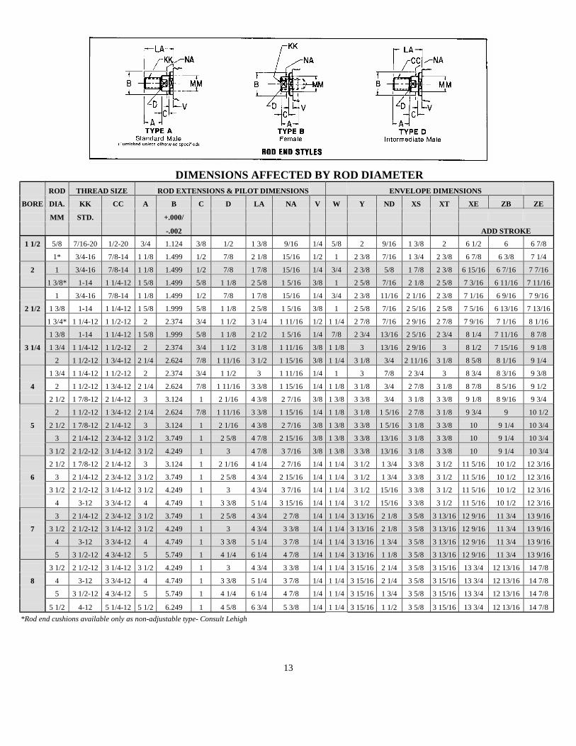
DIMENSIONS AFFECTED BY ROD DIAMETER
ROD THREAD SIZE ROD EXTENSIONS & PILOT DIMENSIONS ENVELOPE DIMENSIONS BORE DIA. KK CC A B C D LA NA V W Y ND XS XT XE ZB ZE
MM STD. +.000/
-.002 ADD STROKE 1 1/2 5/8 7/16-20 1/2-20 3/4 1.124 3/8 1/2 1 3/8 9/16 1/4 5/8 2 9/16 1 3/8 2 6 1/2 6 6 7/8
1* 3/4-16 7/8-14 1 1/8 1.499 1/2 7/8 2 1/8 15/16 1/2 1 2 3/8 7/16 1 3/4 2 3/8 6 7/8 6 3/8 7 1/4
2 1 3/4-16 7/8-14 1 1/8 1.499 1/2 7/8 1 7/8 15/16 1/4 3/4 2 3/8 5/8 1 7/8 2 3/8 6 15/16 6 7/16 7 7/16
1 3/8* 1-14 1 1/4-12 1 5/8 1.499 5/8 1 1/8 2 5/8 1 5/16 3/8 1 2 5/8 7/16 2 1/8 2 5/8 7 3/16 6 11/16 7 11/16
1 3/4-16 7/8-14 1 1/8 1.499 1/2 7/8 1 7/8 15/16 1/4 3/4 2 3/8 11/16 2 1/16 2 3/8 7 1/16 6 9/16 7 9/16
2 1/2 1 3/8 1-14 1 1/4-12 1 5/8 1.999 5/8 1 1/8 2 5/8 1 5/16 3/8 1 2 5/8 7/16 2 5/16 2 5/8 7 5/16 6 13/16 7 13/16
1 3/4* 1 1/4-12 1 1/2-12 2 2.374 3/4 1 1/2 3 1/4 1 11/16 1/2 1 1/4 2 7/8 7/16 2 9/16 2 7/8 7 9/16 7 1/16 8 1/16
1 3/8 1-14 1 1/4-12 1 5/8 1.999 5/8 1 1/8 2 1/2 1 5/16 1/4 7/8 2 3/4 13/16 2 5/16 2 3/4 8 1/4 7 11/16 8 7/8
3 1/4 1 3/4 1 1/4-12 1 1/2-12 2 2.374 3/4 1 1/2 3 1/8 1 11/16 3/8 1 1/8 3 13/16 2 9/16 3 8 1/2 7 15/16 9 1/8
2 1 1/2-12 1 3/4-12 2 1/4 2.624 7/8 1 11/16 3 1/2 1 15/16 3/8 1 1/4 3 1/8 3/4 2 11/16 3 1/8 8 5/8 8 1/16 9 1/4
1 3/4 1 1/4-12 1 1/2-12 2 2.374 3/4 1 1/2 3 1 11/16 1/4 1 3 7/8 2 3/4 3 8 3/4 8 3/16 9 3/8
4 2 1 1/2-12 1 3/4-12 2 1/4 2.624 7/8 1 11/16 3 3/8 1 15/16 1/4 1 1/8 3 1/8 3/4 2 7/8 3 1/8 8 7/8 8 5/16 9 1/2
2 1/2 1 7/8-12 2 1/4-12 3 3.124 1 2 1/16 4 3/8 2 7/16 3/8 1 3/8 3 3/8 3/4 3 1/8 3 3/8 9 1/8 8 9/16 9 3/4
2 1 1/2-12 1 3/4-12 2 1/4 2.624 7/8 1 11/16 3 3/8 1 15/16 1/4 1 1/8 3 1/8 1 5/16 2 7/8 3 1/8 9 3/4 9 10 1/2
5 2 1/2 1 7/8-12 2 1/4-12 3 3.124 1 2 1/16 4 3/8 2 7/16 3/8 1 3/8 3 3/8 1 5/16 3 1/8 3 3/8 10 9 1/4 10 3/4
3 2 1/4-12 2 3/4-12 3 1/2 3.749 1 2 5/8 4 7/8 2 15/16 3/8 1 3/8 3 3/8 13/16 3 1/8 3 3/8 10 9 1/4 10 3/4
3 1/2 2 1/2-12 3 1/4-12 3 1/2 4.249 1 3 4 7/8 3 7/16 3/8 1 3/8 3 3/8 13/16 3 1/8 3 3/8 10 9 1/4 10 3/4
2 1/2 1 7/8-12 2 1/4-12 3 3.124 1 2 1/16 4 1/4 2 7/16 1/4 1 1/4 3 1/2 1 3/4 3 3/8 3 1/2 11 5/16 10 1/2 12 3/16
6 3 2 1/4-12 2 3/4-12 3 1/2 3.749 1 2 5/8 4 3/4 2 15/16 1/4 1 1/4 3 1/2 1 3/4 3 3/8 3 1/2 11 5/16 10 1/2 12 3/16
3 1/2 2 1/2-12 3 1/4-12 3 1/2 4.249 1 3 4 3/4 3 7/16 1/4 1 1/4 3 1/2 15/16 3 3/8 3 1/2 11 5/16 10 1/2 12 3/16
4 3-12 3 3/4-12 4 4.749 1 3 3/8 5 1/4 3 15/16 1/4 1 1/4 3 1/2 15/16 3 3/8 3 1/2 11 5/16 10 1/2 12 3/16
3 2 1/4-12 2 3/4-12 3 1/2 3.749 1 2 5/8 4 3/4 2 7/8 1/4 1 1/4 3 13/16 2 1/8 3 5/8 3 13/16 12 9/16 11 3/4 13 9/16
7 3 1/2 2 1/2-12 3 1/4-12 3 1/2 4.249 1 3 4 3/4 3 3/8 1/4 1 1/4 3 13/16 2 1/8 3 5/8 3 13/16 12 9/16 11 3/4 13 9/16
4 3-12 3 3/4-12 4 4.749 1 3 3/8 5 1/4 3 7/8 1/4 1 1/4 3 13/16 1 3/4 3 5/8 3 13/16 12 9/16 11 3/4 13 9/16
5 3 1/2-12 4 3/4-12 5 5.749 1 4 1/4 6 1/4 4 7/8 1/4 1 1/4 3 13/16 1 1/8 3 5/8 3 13/16 12 9/16 11 3/4 13 9/16
3 1/2 2 1/2-12 3 1/4-12 3 1/2 4.249 1 3 4 3/4 3 3/8 1/4 1 1/4 3 15/16 2 1/4 3 5/8 3 15/16 13 3/4 12 13/16 14 7/8
8 4 3-12 3 3/4-12 4 4.749 1 3 3/8 5 1/4 3 7/8 1/4 1 1/4 3 15/16 2 1/4 3 5/8 3 15/16 13 3/4 12 13/16 14 7/8
5 3 1/2-12 4 3/4-12 5 5.749 1 4 1/4 6 1/4 4 7/8 1/4 1 1/4 3 15/16 1 3/4 3 5/8 3 15/16 13 3/4 12 13/16 14 7/8
5 1/2 4-12 5 1/4-12 5 1/2 6.249 1 4 5/8 6 3/4 5 3/8 1/4 1 1/4 3 15/16 1 1/2 3 5/8 3 15/16 13 3/4 12 13/16 14 7/8 *Rod end cushions available only as non-adjustable type- Consult Lehigh
13

CYLINDER THEORETICAL CAPACITY CHART
1 ½” TO 8” BORE HIGH PRESSURE HYDRAULIC CYLINDERS
See page #19 in catalog #3808 for Piston Rod Selection Chart Description: This chart lists the force and displacement values for the full piston area on the push or extend stroke. Also listed are the force and displacement values for the reduced piston area, depending on rod diameter, for the pull or retraction stroke. Example: Assume 4” bore cylinder with 2” diameter rod, operating at 1000 psi. Using chart, theoretical values as follows are obtained: Push or extend force = 12,566 lbs. Pull or retraction force = 9,424 lbs. Push or extend volume = 12.57 cubic inch/inch of stroke Pull or retraction volume = 9.424 cubic inch/inch of stroke Total volume for one complete reciprocation = 12.57 + 9.424 = 21.994 cubic inch/inch of stroke
PUSH AND PULL STROKE FORCE AND DISPLACEMENT CYLINDER PISTON PISTON FLUID REQUIRED
BORE ROD AREA HYDRAULIC CYLINDER PRESSURE P.S.I PER INCH OF STROKE
DIAMETER DIAMETER SQ. INCH 500 750 1,000 1,500 2,000 2,500 3,000 CUBIC INCH GALLON
* 1.767 883 1,325 1,767 2,651 3,534 4,417 5,301 1.767 .00765
1 1/2 5/8 1.460 730 1,095 1,460 2,190 2,920 3,650 4,380 1.460 .00632
1 .982 491 736 982 1,473 1,964 2,455 2,946 .982 .00425
* 3.141 1,571 2,356 3,141 4,711 6,283 7,853 9,423 3.141 .01360
2 1 2.356 1,178 1,767 2,356 3,534 4,721 5,894 7,068 2.356 .01020
1 3/8 1.656 828 1,242 1,656 2,484 3,312 4,140 4,968 1.656 .00717
* 4.909 2,454 3,682 4,909 7,363 9,818 12,272 14,727 4.909 .02125
2 1/2 1 4.124 2,062 3,093 4,124 6,186 8,248 10,310 12,372 4.124 .01785
1 3/8 3.424 1,712 2,568 3,424 5,136 6,848 8,560 10,272 3.424 .01482
1 3/4 2.504 1,252 1,878 2,504 3,756 5,008 6,260 7,512 2.504 .01084
* 8.296 4,148 6,222 8,296 12,444 16,592 20,740 24,888 8.296 .0359
3 1/4 1 3/8 6.811 3,405 5,108 6,811 10,216 13,622 17,027 20,433 6.811 .0259
1 3/4 5.891 2,945 4,418 5,891 8,836 11,782 14,727 17,673 5.891 .0225
2 5.145 2,577 3,865 5,154 7,731 10,308 12,890 15,462 5.154 .0223
* 12.57 6,283 9,425 12,566 18,849 25,132 31,415 37,698 12.57 .0544
4 1 3/4 10.16 5,080 7,621 10,161 15,241 20,322 25,402 30,483 10.16 .0440
2 9.424 4,712 7,068 9,424 14,136 18,848 23,560 28,272 9.424 .0408
2 1/2 7.657 3,828 5,743 7,657 11,485 15,314 19,142 22,971 7.657 .0331
* 19.64 9,818 14,726 19,635 29,453 39,270 49,087 58,905 19.64 .0850
2 16.49 8,246 12,369 16,492 24,738 32,648 41,212 49,476 16.49 .0714
5 2 1/2 14.73 7,363 11,044 14,726 22,089 29,542 36,815 44,178 14.73 .0637
3 12.57 6,283 9,424 12,566 18,849 25,132 31,415 37,698 12.57 .0544
3 1/2 10.01 5,007 7,510 10,014 15,021 20,028 25,035 30,042 10.01 .0433
* 28.27 14,137 21,205 28,274 42,411 56,548 70,685 84,822 28.27 .1224
2 1/2 23.37 11,682 17,524 23,365 35,047 46,730 58,412 70,095 23.37 .1011
6 3 21.21 10,602 15,904 21,205 31,807 42,410 53,012 63,615 21.21 .0918
3 1/2 18.65 9,326 13,990 18,653 27,979 37,306 46,632 55,959 18.65 .0807
4 15.71 7,854 11,781 15,708 23,562 31,416 39,270 47,124 15.71 .0680
* 38.48 19,242 28,864 38,485 57,728 76,970 96,213 115,445 38.48 .1666
3 31.42 15,708 23,562 31,416 47,124 62,832 78,540 92,248 31.42 .1360
7 3 1/2 28.86 14,432 21,648 28,864 43,296 57,728 72,160 86,592 28.86 .1250
4 25.92 12,957 19,436 25,916 38,872 51,830 64,787 77,745 25.92 .1122
5 18.85 9,425 14,137 18,850 28,275 37,700 47,125 56,550 18.85 .0816
* 50.26 25,132 37,698 50,265 75,398 100,530 125,663 150,795 50.27 .2176
3 1/2 40.64 20,322 30,483 40,644 60,966 81,288 101,610 121,932 40.64 .1759
8 4 37.70 18,850 28,273 37,699 56,548 75,398 94,247 113,097 37.70 .1632
5 30.63 15,315 22,973 30,630 45,945 61,260 76,575 91,890 30.62 .1326
5 1/2 26.51 13,253 19,880 26,507 39,760 53,014 66,267 79,521 26.51 .1147
*Full piston area (see DESCRPTION paragraph).
14


Lehigh Fluid Power, Inc.
Warranty Seller warrants its products free from defects in material and workmanship for a period of one year from date of shipment. This warranty excludes normal wear attributable to the particular application in which the product is used. Further, this warranty is limited exclusively to the replacement or repair of defective products, which, in the opinion of Lehigh Fluid Power, Inc., have not been modified, misused, misapplied, repaired, or altered by the user. Lehigh Fluid Power, Inc. accepts no responsibility or liability for damages to the purchaser arising out of a delay or failure of delivery or resulting from any breach of any other term or obligation of Lehigh under this contract. In order to make a claim, buyer must notify Lehigh within the warranty period. Promptly after receiving such notification, Lehigh will either examine the product at the user’s site or issue shipping instructions for return to it, transportation costs prepaid by buyer. All items returned must be accompanied by a copy of this acknowledgement. The above warranty comprises Lehigh’s sole and entire obligation and liability to buyer and all those claiming under buyer as to the products sold hereunder. All other warranties, express or implied, including but not limited to, warranties or merchantability and fitness, are expressly excluded. These terms and conditions of sale constitute the complete and exclusive statement of agreement superseding all oral or written communications and any prior agreements between the parties relating to its subject matter. THE COMPANY’S ACCEPTANCE OF THIS ORDER IS MADE EXPRESSLY CONDITIONAL UPON THE FOREGOING TERMS AND CONDITIONS.