Legacy report on the 1997 Uniform Building...
28
LEGACY REPORT Business/Regional Office # 5360 Workman Mill Road, Whittier, California 90601 # (562) 699-0543 Regional Office # 900 Montclair Road, Suite A, Birmingham, Alabama 35213 # (205) 599-9800 Regional Office # 4051 West Flossmoor Road, Country Club Hills, Illinois 60478 # (708) 799-2305 ICC Evaluation Service, Inc. www.icc-es.org Legacy report on the 1997 Uniform Building Code™ ER-5239 Reissued January 1, 2004 Copyright © 2004 Page 1 of 28 ICC-ES legacy reports are not to be construed as representing aesthetics or any other attributes not specifically addressed, nor are they to be construed as an endorsement of the subject of the report or a recommendation for its use. There is no warranty by ICC Evaluation Service, Inc., express or implied, as to any finding or other matter in this report, or as to any product covered by the report. DIVISION: 05—METALS Section: 05310—Steel Deck DECK WEST STEEL FLOOR AND ROOF DECKS DECK WEST, INC. 1900 SANGUINETTI LANE STOCKTON, CALIFORNIA 95205 1.0 SUBJECT Deck West Steel Floor and Roof Decks. 2.0 DESCRIPTION 2.1 General: The Deck West roof and floor panels are cold-rolled from steel sheets conforming to ASTM A 653 SS Grade 40 with galvanized finish, or ASTM A 611 with a painted finish or a mill finish.The minimum yield strength is 46,000 psi (320 MPa) and the minimum tensile strength is 55,000 psi (380 MPa). Deck types include BADW, BDW, NDW, 2DW and 3DW. Section properties and minimum design thicknesses are shown in Table D-1, and deck profiles are shown in Figure D. Diaphragm shear values and vertical load capacities for various deck sections are set forth in the tables included with this report. The Table of Contents for Tables and Figures summarizes the information to be found within this evaluation report. 2.2 Welding: Spot puddle welds for field assembly of steel decking must have a minimum fusion area measuring 1 / 2 inch (12.7 mm) in diameter or 3 / 8 inch wide by 1 inch long (9.5 mm by 12.7 mm). Seam welds must be a minimum of 1 / 2 inch (12.7 mm) long. Weld requirements must comply with American Welding Society (AWS) Standard D1.3-98. Minimum E60 XX or E70 XX filler metal complying with the appropriate AWS standard is used. See Table C-1 and Figure C for additional details. Prior to proceeding with the welding, the welder shall demonstrate to the welding inspector his ability to produce the prescribed weld. 2.3 SHEARCORR: This is a special edge stiffening system consisting of a No. 18 gage stiffened, corrugated member in conjunction with the BDW deck. The SHEARCORR is used only at shear collecting elements transverse to the corrugations. All end laps at end supports must be a minimum of 2 inches (51 mm), fastened to supports with arc spot (puddle) welds. Allowable shears, and flexibility factors and details, are in Table A-4 and Figure A. 2.4 Acoustical Deck: BDW and NDW types are available as acoustical deck. Data in Tables A-1 and A-2 also apply to acoustical versions. The width of the perforated area is 0.85 inch (21.6 mm) for BDW and 1.80 inches (45.7 mm) for the NDW to outside of holes, centered on each web running the full panel length. The pattern consists of 1 / 8 -inch-diameter (3.2 mm) holes spaced 7 / 16 inch (11.1 mm) on center transverse to the panel length and 3 / 8 inch (9.5 mm) on center staggered longitudinally. Acoustical uses are limited to nonfire-resistive assemblies. 2.5 Design: 2.5.1 General: Section properties and minimum design thicknesses are shown in Table D-1, and deck profiles are shown in Figure D. The concrete fill utilizes normal-weight or expanded shale structural lightweight aggregates and must have a minimum compressive strength of 3,000 psi (20.7 MPa). Additional design criteria are in the general notes. 2.5.2 Vertical Composite Load: Values in tables indicate maximum unshored clear spans and the allowable superimposed loads based on simple-span condition for composite behavior. The determination of shoring limits is based on the strength or deflection of the deck section, using the greater of construction uniform live load of 20 psf (957 Pa) or a concentrated construction load of 150 pounds (667 N). Composite sections shall not be used for vertical loads which are predominately vibratory, such as continuous operation of heavy machinery. Vertical load design shall be based on section properties set forth in this report or, where composite action is considered, in accordance with the tables in this report. Web crippling must be considered in accordance with Table F-1. 2.5.3 Diaphragms: The allowable shears for wind or earthquake, in pounds per linear foot (N/m), shall not exceed the values set forth in the tables for the type of deck involved. Consideration shall be given to diaphragm deflection requirements set forth in Table E-1. For decks with no trench header and with concrete fills, the flexibility factor (F) may be taken as one. The flexibility factor (F) is the average in micro inches (2.54 x 10 -5 mm) that a diaphragm web will deflect in a span of 1 foot (304.8 mm) under a shear of 1 pound per foot (14.55 N/m). The diaphragm design must include the following considerations: 1. Diaphragm classification (flexible or rigid) must comply with Section 1630.6 of the 1997 Uniform Building Code ™ (UBC); the diaphragm deflection (ª) must be calculated using the equation noted in Table E-1.
Transcript of Legacy report on the 1997 Uniform Building...

LEGACY REPORT
Business/Regional Office # 5360 Workman Mill Road, Whittier, California 90601 # (562) 699-0543Regional Office # 900 Montclair Road, Suite A, Birmingham, Alabama 35213 # (205) 599-9800Regional Office # 4051 West Flossmoor Road, Country Club Hills, Illinois 60478 # (708) 799-2305
ICC Evaluation Service, Inc.www.icc-es.org
Legacy report on the 1997 Uniform Building Code™
ER-5239Reissued January 1, 2004
Copyright © 2004Page 1 of 28
ICC-ES legacy reports are not to be construed as representing aesthetics or any other attributes not specifically addressed, nor are they to be construed as
an endorsement of the subject of the report or a recommendation for its use. There is no warranty by ICC Evaluation Service, Inc., express or implied, as to
any finding or other matter in this report, or as to any product covered by the report.
DIVISION: 05—METALSSection: 05310—Steel Deck
DECK WEST STEEL FLOOR AND ROOF DECKS
DECK WEST, INC.1900 SANGUINETTI LANESTOCKTON, CALIFORNIA 95205
1.0 SUBJECT
Deck West Steel Floor and Roof Decks.
2.0 DESCRIPTION
2.1 General:
The Deck West roof and floor panels are cold-rolled fromsteel sheets conforming to ASTM A 653 SS Grade 40 withgalvanized finish, or ASTM A 611 with a painted finish or amill finish.The minimum yield strength is 46,000 psi (320MPa) and the minimum tensile strength is 55,000 psi (380MPa). Deck types include BADW, BDW, NDW, 2DW and3DW. Section properties and minimum design thicknessesare shown in Table D-1, and deck profiles are shown inFigure D. Diaphragm shear values and vertical loadcapacities for various deck sections are set forth in the tablesincluded with this report. The Table of Contents for Tablesand Figures summarizes the information to be found withinthis evaluation report.
2.2 Welding:
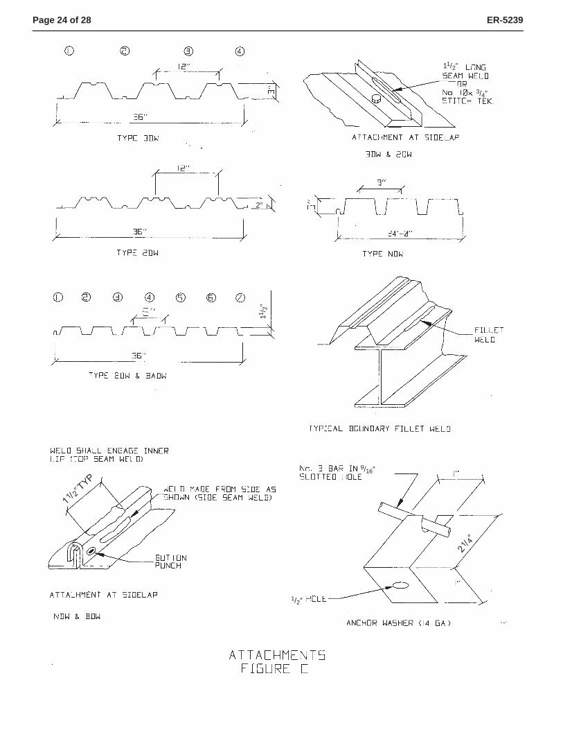
Spot puddle welds for field assembly of steel decking musthave a minimum fusion area measuring 1/2 inch (12.7 mm) indiameter or 3/8 inch wide by 1 inch long (9.5 mm by 12.7 mm).Seam welds must be a minimum of 1/2 inch (12.7 mm) long.Weld requirements must comply with American WeldingSociety (AWS) Standard D1.3-98. Minimum E60 XX or E70XX filler metal complying with the appropriate AWS standardis used. See Table C-1 and Figure C for additional details.Prior to proceeding with the welding, the welder shalldemonstrate to the welding inspector his ability to produce theprescribed weld.
2.3 SHEARCORR:
This is a special edge stiffening system consisting of a No. 18gage stiffened, corrugated member in conjunction with theBDW deck. The SHEARCORR is used only at shearcollecting elements transverse to the corrugations. All endlaps at end supports must be a minimum of 2 inches (51 mm),fastened to supports with arc spot (puddle) welds. Allowableshears, and flexibility factors and details, are in Table A-4 andFigure A.
2.4 Acoustical Deck:
BDW and NDW types are available as acoustical deck. Datain Tables A-1 and A-2 also apply to acoustical versions. Thewidth of the perforated area is 0.85 inch (21.6 mm) for BDWand 1.80 inches (45.7 mm) for the NDW to outside of holes,centered on each web running the full panel length. Thepattern consists of 1/8-inch-diameter (3.2 mm) holes spaced7/16 inch (11.1 mm) on center transverse to the panel lengthand 3/8 inch (9.5 mm) on center staggered longitudinally.Acoustical uses are limited to nonfire-resistive assemblies.
2.5 Design:
2.5.1 General: Section properties and minimum designthicknesses are shown in Table D-1, and deck profiles areshown in Figure D. The concrete fill utilizes normal-weight orexpanded shale structural lightweight aggregates and musthave a minimum compressive strength of 3,000 psi (20.7MPa). Additional design criteria are in the general notes.
2.5.2 Vertical Composite Load: Values in tables indicatemaximum unshored clear spans and the allowablesuperimposed loads based on simple-span condition forcomposite behavior. The determination of shoring limits isbased on the strength or deflection of the deck section, usingthe greater of construction uniform live load of 20 psf (957 Pa)or a concentrated construction load of 150 pounds (667 N).Composite sections shall not be used for vertical loads whichare predominately vibratory, such as continuous operation ofheavy machinery. Vertical load design shall be based onsection properties set forth in this report or, where compositeaction is considered, in accordance with the tables in thisreport. Web crippling must be considered in accordance withTable F-1.
2.5.3 Diaphragms: The allowable shears for wind orearthquake, in pounds per linear foot (N/m), shall not exceedthe values set forth in the tables for the type of deck involved.Consideration shall be given to diaphragm deflectionrequirements set forth in Table E-1. For decks with no trenchheader and with concrete fills, the flexibility factor (F) may betaken as one.
The flexibility factor (F) is the average in micro inches (2.54x 10⁻⁵ mm) that a diaphragm web will deflect in a span of 1foot (304.8 mm) under a shear of 1 pound per foot (14.55N/m).
The diaphragm design must include the followingconsiderations:
1. Diaphragm classification (flexible or rigid) must complywith Section 1630.6 of the 1997 Uniform Building Code™
(UBC); the diaphragm deflection (ª) must be calculatedusing the equation noted in Table E-1.

Page 2 of 28 ER-5239
2. Diaphragm flexibility limitations must comply with Table E-1.
3. Diaphragm deflection limits must comply with Section1633.2.9 of the UBC.
4. Horizontal shears must be distributed in accordance withSections 1630.6 and 1630.7 of the UBC.
2.6 Fire-resistive Floor and Roof Construction:
Fire-resistive ratings for unprotected steel decks are set forthin Table 1.
2.7 Concrete Diaphragms with Shear Studs:
Concrete diaphragms with shear connector studs may beused with Types BDW, 2DW and 3DW. Details are in TableB-9. Shear connector studs may replace arc-spot welds.
2.8 Special Inspection:
2.8.1 Concrete: Special inspection for concrete andconcrete reinforcement must be conducted in accordancewith Section 1701.5.1 of the UBC. The inspector’s dutiesinclude sampling and testing of concrete, and verification ofconcrete mixes, reinforcement types and placement, andconcrete placement.
2.8.2 Welding: Special inspection for welding must beconducted in accordance with Section 1701.5.5 of the UBC.Before proceeding, the welder must demonstrate to thespecial inspector’s satisfaction his ability to produce theprescribed weld. The inspector’s other duties includeverification of materials, weld preparation, weldingprocedures, and welding processes.
2.9 Identification:
Each bundle of deck must be identified by a label, bearing thejob and work order, that indicates the manufacturer’s name(Deck West, Inc.) and address, type and gage of the decks,and the evaluation report number (ER-5239).
3.0 EVIDENCE SUBMITTED
Data in accordance with the ICC-ES Interim Criteria for SteelDecks (AC43), dated January 2002. Data included reportsand analysis of tests on full-scale diaphragms; fire tests inaccordance with UBC Standard 7-1; load test results toestablish criteria for composite action; structural calculations;and quality control manuals on deck forming and resistancewelding.
4.0 FINDINGS
That the Deck West Steel Floor and Roof Decks describedin this report comply with the 1997 Uniform BuildingCode™ for use as floor or roof systems to resist verticalor horizontal forces, subject to the following conditions:
4.1 Where used as diaphragms:
4.1.1 The one-third stress increase (or 0.75reduction of the resulting forces) permittedfor Allowable Stress Design in the buildingcode for load combinations containing windor seismic forces shall not be used for shearvalues in the diaphragm tables.
4.1.2 Allowable shear values are as set forth in thetables accompanying this report for the typeof deck involved.
4.1.3 Diaphragm deflections shall not exceed thepermitted relative deflections of wallsbetween the diaphragm level and the floorbelow. The flexibility limitations shown inTable E-1 may be used as a guide in lieu of arational analysis of the anticipateddeflections.
4.1.4 Diaphragms may be zoned by varying deckgage and/or connections across a diaphragmto meet varying shear and flexibilitydemands.
4.2 Composite sections shall not be used for loadswhich are predominately vibratory.
4.3 Vertical load design of deck without concrete fill isbased on section properties set forth in this report.Allowable reactions based on web crippling arebased on Table F-1 of this report. Vertical loadcapability of concrete-filled composite deck systemis set forth in the tables within this report.
4.4 The minimum 28-day compressive strength ofconcrete shall be 3,000 psi (20.6 MPa), except asnoted in this report.
4.5 The steel decks are welded as set forth in the tablesaccompanying this report for the particular deckinvolved.
4.6 Special inspection is provided for concrete and on-site welding as noted in Section 2.8 of this report.
4.7 The decks are manufactured and installed inaccordance with this report.
4.8 Allowable loads and deflections are as set forth inthis report. Structural calculations demonstratingthat the applied loads comply with this report shallbe submitted to the building official for approval.
4.9 The decks are produced at 1900 Sanguinetti Lane,Stockton, California.
This report is subject to re-examination in two years.

Page 3 of 28 ER-5239
TABLE 1—RESTRAINED FIRE-RESISTIVE ASSEMBLIES
DECK SECTION TYPE OF CONCRETE MINIMUM CONCRETETHICKNESS ABOVE TOP
FLUTE (inches)
CLEAR SPAN MAXIMUM FIRE-RESISTIVETIME PERIOD
(hours)
3"-DW2"-DW
3,000 psi lightweight
21/2
13' 2"
1
31/4 2
43/16 3
3"-DW2"-DW 3,500 psi stone aggregate
31/2 13' 2"1
41/2 2
N-DWB-DW 3,000 psi lightweight 31/4 12' 2
N-DWB-DW 3,500 psi stone aggregate 41/2 12' 2
For SI: 1 inch = 25.4 mm, 1 foot = 304.8 mm, 1 psi = 6.89 kPa.
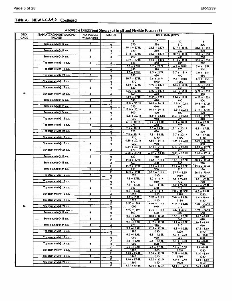
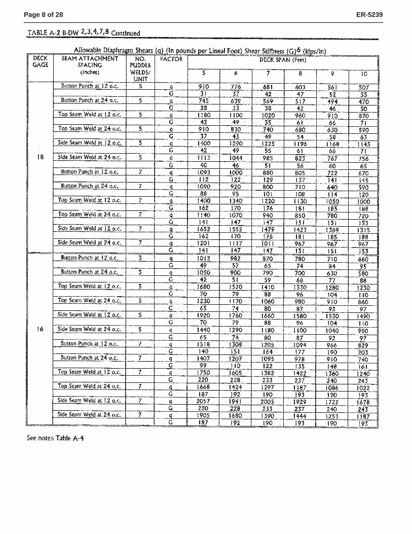
GENERAL NOTES: The following notes apply to all of the accompanying tables unless otherwise noted:1. The allowable diaphragm shears ( q) listed in the tables are in pounds per lineal foot (N/m).2. Allowable superimposed loads listed in the tables are in pounds per square foot (Pa).3. The base metal thickness for all decks is indicated in Table D1.4. Deck panel seams may be fastened by welds, button punches or No. 10 stitch screws, as indicated in this report.
The length of seam welds shall be a minimum of 11/2 inches (38 mm). The seam attachment, where required,shall be in accordance with the appropriate table, not to exceed 3 feet (914 mm) on center.
5. Arc seam or spot (puddle) welds shall have an effective fusion area to supporting members at least equivalentto 3/8 inch (9.5 mm) by 1 inch (25 mm) long, or 1/2 inch (12.7 mm) in diameter, respectively, as illustrated in FigureC.
6. Puddle weld patterns for Types BDW, BADW, NDW, 2DW and 3DW are in Table C-1 and Figure C. TheSHEARCORR Edge Stiffening System is described in Table A-4 and Figure A.
7. Spacing of marginal welds to members parallel to flutes:a. Arc seam or spot (puddle) welds to members such as chords and to collector elements such as struts or
ties shall have a spacing in feet (mm) equal to 32,000 t/v (SI: 5,605 t/v),where:t = Uncoated steel thickness of fluted deck, in inches (mm).v = Actual diaphragm shear at boundary supports or actual shear transferred to collector (at struts of
ties), in pounds per foot (N/mm).b. Fillet welds to members such as diaphragm chords shall have a spacing in feet equal to 480 (lw)/ v (SI: 84
lw/v),where:lw = Length of weld, in inches (not less than 11/2 inches).v = Actual diaphragm unit shear to be transferred to chords, in pounds per foot (N/mm).
c. Fillet welds attaching the diaphragms to struts, ties or other collector elements shall have spacing in feet(mm) equal to 300 (lw)/V (SI: 53 lw/v), where v is the actual total shear to be transferred to the collectorelement.
d. Weld spacing is limited to 3 feet (914 mm), maximum.8. Attachments at interior lines of shear transfer perpendicular to deck corrugations:
a. The shear transfers from a diaphragm to interior tie or strut lines perpendicular to deck corrugations shallnot exceed the shear values indicated in the tables. Two lines of puddle welds may be used to develop theactual shear transfer to these collector elements.
b. In no case shall the spacing of welds exceed the deck span divided by three, except for those systems withfill and no seam fastening or as otherwise noted.
9. Where individual panels are cut, the partial panel shall be fastened in a manner to fully transfer the shears atthe point of the diaphragm to the adjacent full panels for the values specified in the tables.
10. The minimum 28-day compressive strength for structural concrete shall be 3,000 psi (20.7 MPa). Theappropriate concrete density (normal-weight or lightweight) is indicated in the tables. The minimum concretedepth shall be 2 inches (51 mm) over the top flange and shall be reinforced with a minimum 6 × 6 W1.4 weldedwire fabric. The reinforcement shall be placed near the center of the fill over the top flange. If the fill exceeds a31/4-inch (82 mm) thickness over the top flange, an area of reinforcement in each direction equal to 0.01 timesthe depth of fill is required.
11. All decks with structural concrete fill may be considered rigid diaphragms, i.e., flexibility factor F < 1.0.12. For decks with concrete fill, the diaphragm shear values and flexibility factors apply to deck sections with or
without embossments.13. The diaphragm shear values, for decks without fill, also apply to the acoustical version of the specific deck.14. Composite deck panel seams shall be fastened at 3 feet (914 mm), maximum, to reduce differential deflection
during concrete placement.

Page 4 of 28 ER-5239
TABLE OF CONTENTS FOR TABLES AND FIGURES
DIAPHRAGM SHEARS WITHOUT CONCRETE
Table A-1 NDWTable A-2 BDWTable A-3 BADW with Seam WeldsTable A-4 BDW with SHEARCORR Edge Stiffening SystemFigure A Edge Stiffening Details
ALLOWABLE SUPERIMPOSED LOADS AND DIAPHRAGM SHEARS WITH CONCRETE FILL
Table B-1 11/2 BDW with Lightweight Concrete FillTable B-2 11/2 BDW with Normal-weight Concrete FillTable B-3 2DW with Lightweight Concrete FillTable B-4 2DW with Normal-weight Concrete FillTable B-5 3DW with Lightweight Concrete FillTable B-6 3DW with Lightweight Concrete FillTable B-7 BDW and BADW with 2" Insulating Concrete FillTable B-8 ReinforcingTable B-9 Allowable Diaphragm Shears for BDW, 2DW and 3DW Deck with Concrete Fill and Shear StudsFigure B Shear Stud Details
DIAPHRAGM WELDING
Table C-1 Welding Schedule for 3DW, 2DW, NDW, BDW and BADW. Allowable Shear for Boundary PuddleWelds
Figure C Attachments
SECTION PROPERTIES
Table D-1 Deck Section PropertiesFigure D Section Profile Drawings
DIAPHRAGM FLEXIBILITY LIMITATIONS
Table E-1
WEB CRIPPLING
Table F-1

Page 5 of 28 ER-5239
Page 6 of 28 ER-5239

Page 7 of 28 ER-5239
Page 8 of 28 ER-5239

Page 9 of 28 ER-5239

Page 10 of 28 ER-5239

Page 11 of 28 ER-5239
����″
����″
���″
���″

Page 12 of 28 ER-5239

Page 13 of 28 ER-5239

Page 14 of 28 ER-5239

Page 15 of 28 ER-5239

Page 16 of 28 ER-5239

Page 17 of 28 ER-5239

Page 18 of 28 ER-5239

Page 19 of 28 ER-5239

Page 20 of 28 ER-5239

Page 21 of 28 ER-5239

Page 22 of 28 ER-5239
����″
����″����″

Page 23 of 28 ER-5239
Page 24 of 28 ER-5239
11/2″
3/4″
2″
11/ 2
″
9/16″
1/2″

Page 25 of 28 ER-5239

Page 26 of 28 ER-5239
11/2″
1 /2″
43/4″ 71/4″
43/4″
71/4″
43/4″1 /2″
3 /8″
3 /8″
3/8″
0.060″
R3/16″
R3/16″ R3/16″
43/4″
13/8″0.0875″
3 /8″
R.125″1.125″
0.056″
R1/16″
R1/16″1 /
2″
31/2″
11/ 2
″ 23/8″
57/8″21/8″
31/2″
11/ 2
″
3 /8″ 1 /
2″
23/4″
3 /8″
0.060″ MIN INDENT
3 /8″
3 /8″

TABLE E-1—DIAPHRAGM FLEXIBILITY LIMITATION1,2,3,4,5
F MAXIMUM SPAN INFEET FOR MASONRY
OR CONCRETE WALLS
SPAN-DEPTH LIMITATION
Rotation Not Considered in Diaphragm Rotation Considered in Diaphragm
Masonry or Concrete Walls Flexible Walls Masonry or Concrete Walls Flexible Walls
More than 150 Not used Not used 2:1 Not used 11/2:1
70 - 150 200 2:1 or as required for deflection 3:1 Not used 2:1
10 - 70 400 21/2:1 or as required for deflection 4:1 As required for deflection 21/2:1
1 - 10 No limitation 3:1 or as required for deflection 5:1 As required for deflection 3:1
Less than 1 No limitation As required for deflection No limitation As required for deflection 31/2:1For SI: 1 inch = 25.4 mm, 1 foot = 304.8 mm, 1 plf = 14.594 N/m, 1 psi = 6894 Pa.
1Roof diaphragms shall be investigated regarding their flexibility and suggested span-depth ratio. Refer to the above tables for determinationof F.2When diaphragms are supporting masonry or concrete walls, the maximum deflection of the diaphragm should be computed using the loadsin UBC Section 1612.3.1 and it should be limited to the amount *wall given by the following formula in inches (mm):
*wall = H f
ETH f
Etc c
2 2
0.01694,000
where:
H = Unsupported height of wall, in feet (m).t = Thickness of wall, in inches (mm).E = Modulus of Elasticity of wall material for deflection determination, in pounds per square inch (MPa).fc = Allowable compressive strength of wall material in flexure, in pounds per square inch (MPa) (fc = 0.45
fNm for concrete and fm = 0.033 fNm for masonry).
3When applying these limitations to cantilever diaphragms, the suggested span-depth ratio shall be 1/2 of those shown.4The total deflection ) of the diaphragm in inches (mm) shall be computed from the equation
) = )f + )w
where:
)f = Flexural deflection of the diaphragm in inches (mm) determined in the same manner as the deflectionof beams.
)w = The web deflection as determined by the equation.)w = L1qaveF/106 (L1qaveF/175).
where:
)w = Shear deflection of diaphragm web, in inches (mm), over span L1.F = Flexibility factor (the average micro inches a diaphragm web will deflect on a span of 1 foot under a
shear load of 1 pound per foot.L1 = Span between points for which deflection is determined, in feet (m).qave = Average required shear, in pounds per foot (kN/m), over span L1.
5Diaphragm classification (flexible or rigid) and deflection limits shall comply with Section 2.5.3 of this report.
Page 27 of 28 ER-5239

Page 28 of 28 ER-5239