LED solutions DC-String Product Manual - Tridonic
54
LED solutions DC-String Product Manual
Transcript of LED solutions DC-String Product Manual - Tridonic
LED solutions
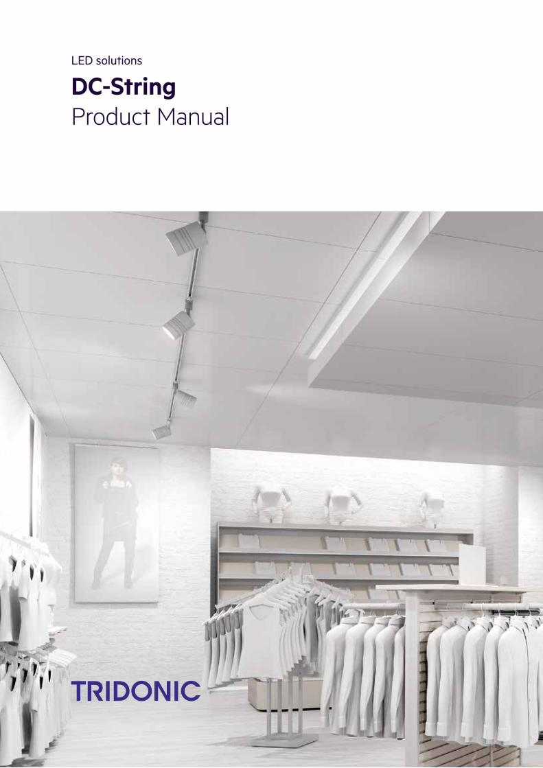
DC-StringProduct Manual

Table of Contents
c 2 / 54
Table of Contents
1 Validity . . . . . . . . . . . . . . . . . . . . . . . . . . . . . . . . . . . . . . . . . . . . . . . . . . . . . . . . . . . . . . . . . . . . . . . . . 41.1 Copyright . . . . . . . . . . . . . . . . . . . . . . . . . . . . . . . . . . . . . . . . . . . . . . . . . . . . . . . . . . . . . . . . . . . . . . . . . . . . . 4
1.2 Imprint . . . . . . . . . . . . . . . . . . . . . . . . . . . . . . . . . . . . . . . . . . . . . . . . . . . . . . . . . . . . . . . . . . . . . . . . . . . . . . . 4
2 General safety instructions . . . . . . . . . . . . . . . . . . . . . . . . . . . . . . . . . . . . . . . . . . . . . . . . . . . . . . . . 52.1 Intended use . . . . . . . . . . . . . . . . . . . . . . . . . . . . . . . . . . . . . . . . . . . . . . . . . . . . . . . . . . . . . . . . . . . . . . . . . . 5
2.2 Dangers associated with the operation of the system . . . . . . . . . . . . . . . . . . . . . . . . . . . . . . . . . . . . . . . . . . . 5
2.3 Environment . . . . . . . . . . . . . . . . . . . . . . . . . . . . . . . . . . . . . . . . . . . . . . . . . . . . . . . . . . . . . . . . . . . . . . . . . . . 5
2.4 Additional instructions . . . . . . . . . . . . . . . . . . . . . . . . . . . . . . . . . . . . . . . . . . . . . . . . . . . . . . . . . . . . . . . . . . . 6
3 Key features . . . . . . . . . . . . . . . . . . . . . . . . . . . . . . . . . . . . . . . . . . . . . . . . . . . . . . . . . . . . . . . . . . . . 73.1 Description of key features . . . . . . . . . . . . . . . . . . . . . . . . . . . . . . . . . . . . . . . . . . . . . . . . . . . . . . . . . . . . . . . 7
3.2 Two-part layer structure . . . . . . . . . . . . . . . . . . . . . . . . . . . . . . . . . . . . . . . . . . . . . . . . . . . . . . . . . . . . . . . . . . 8
3.3 Adjustable Output Current and Output Voltage . . . . . . . . . . . . . . . . . . . . . . . . . . . . . . . . . . . . . . . . . . . . . . . 10
3.4 Housing variants . . . . . . . . . . . . . . . . . . . . . . . . . . . . . . . . . . . . . . . . . . . . . . . . . . . . . . . . . . . . . . . . . . . . . . 12
4 Compatibility between LED module and LMI DC LED Driver . . . . . . . . . . . . . . . . . . . . . . . . . . . . 14
4.1 Comparison of data sheet values with a 4-point guideline . . . . . . . . . . . . . . . . . . . . . . . . . . . . . . . . . . . . . . 14
4.2 Application of the 4-point guideline . . . . . . . . . . . . . . . . . . . . . . . . . . . . . . . . . . . . . . . . . . . . . . . . . . . . . . . . 16
4.3 Practical tests . . . . . . . . . . . . . . . . . . . . . . . . . . . . . . . . . . . . . . . . . . . . . . . . . . . . . . . . . . . . . . . . . . . . . . . . . 20
4.4 Standards and directives . . . . . . . . . . . . . . . . . . . . . . . . . . . . . . . . . . . . . . . . . . . . . . . . . . . . . . . . . . . . . . . . 21
5 Installation . . . . . . . . . . . . . . . . . . . . . . . . . . . . . . . . . . . . . . . . . . . . . . . . . . . . . . . . . . . . . . . . . . . . . 24
5.1 Guideline for installation . . . . . . . . . . . . . . . . . . . . . . . . . . . . . . . . . . . . . . . . . . . . . . . . . . . . . . . . . . . . . . . . . 24
5.2 Protection measures against damage . . . . . . . . . . . . . . . . . . . . . . . . . . . . . . . . . . . . . . . . . . . . . . . . . . . . . . 24
6 Electrical Aspects . . . . . . . . . . . . . . . . . . . . . . . . . . . . . . . . . . . . . . . . . . . . . . . . . . . . . . . . . . . . . . . 26
6.1 Wiring diagrams . . . . . . . . . . . . . . . . . . . . . . . . . . . . . . . . . . . . . . . . . . . . . . . . . . . . . . . . . . . . . . . . . . . . . . . 27
6.2 Function of the earth terminal . . . . . . . . . . . . . . . . . . . . . . . . . . . . . . . . . . . . . . . . . . . . . . . . . . . . . . . . . . . . 29
6.3 Routing the wires . . . . . . . . . . . . . . . . . . . . . . . . . . . . . . . . . . . . . . . . . . . . . . . . . . . . . . . . . . . . . . . . . . . . . . 30
6.4 Maximum loading of circuit breakers . . . . . . . . . . . . . . . . . . . . . . . . . . . . . . . . . . . . . . . . . . . . . . . . . . . . . . . 33
7 Functions . . . . . . . . . . . . . . . . . . . . . . . . . . . . . . . . . . . . . . . . . . . . . . . . . . . . . . . . . . . . . . . . . . . . . . 37
7.1 corridorFUNCTION V2 (combination of LCU DIM and LMI DIM only) . . . . . . . . . . . . . . . . . . . . . . . . . . . . . . 37
7.2 DALI (LCU DIM only) . . . . . . . . . . . . . . . . . . . . . . . . . . . . . . . . . . . . . . . . . . . . . . . . . . . . . . . . . . . . . . . . . . . 43
7.3 DSI (LCU DIM only) . . . . . . . . . . . . . . . . . . . . . . . . . . . . . . . . . . . . . . . . . . . . . . . . . . . . . . . . . . . . . . . . . . . . 45
7.4 switchDIM (LCU DIM only) . . . . . . . . . . . . . . . . . . . . . . . . . . . . . . . . . . . . . . . . . . . . . . . . . . . . . . . . . . . . . . . 46
7.5 Constant Light Output (LMI DIM only) . . . . . . . . . . . . . . . . . . . . . . . . . . . . . . . . . . . . . . . . . . . . . . . . . . . . . . 50
7.6 Intelligent Temperature Guard . . . . . . . . . . . . . . . . . . . . . . . . . . . . . . . . . . . . . . . . . . . . . . . . . . . . . . . . . . . . 52
7.7 Power-up Fading (combination of LCU DIM and LMI DIM only) . . . . . . . . . . . . . . . . . . . . . . . . . . . . . . . . . . 53
8 Reference list . . . . . . . . . . . . . . . . . . . . . . . . . . . . . . . . . . . . . . . . . . . . . . . . . . . . . . . . . . . . . . . . . . 54

Table of Contents
c 3 / 54
...
8 Reference list . . . . . . . . . . . . . . . . . . . . . . . . . . . . . . . . . . . . . . . . . . . . . . . . . . . . . . . . . . . . . . . . . . . 54
8.1 Additional information . . . . . . . . . . . . . . . . . . . . . . . . . . . . . . . . . . . . . . . . . . . . . . . . . . . . . . . . . . . . . . . . . . 54
8.2 Downloads . . . . . . . . . . . . . . . . . . . . . . . . . . . . . . . . . . . . . . . . . . . . . . . . . . . . . . . . . . . . . . . . . . . . . . . . . . . 54
8.3 Technical data . . . . . . . . . . . . . . . . . . . . . . . . . . . . . . . . . . . . . . . . . . . . . . . . . . . . . . . . . . . . . . . . . . . . . . . . 54

Product manual DC-String | 12-2016 | 1.0 | en
Scope of documentation
c 4 / 54
1. ValidityThese operating instructions are valid for LCU DC power supply devices and LMI DC LED Drivers.If a reference is made to one of the two versions then the descriptions are valid only for that version.
TRIDONIC GmbH & Co KG is constantly striving to develop all its products. This means that there may be changesin form, equipment and technology.Claims cannot therefore be made on the basis of information, diagrams or descriptions in these instructions.The latest version of these operating instructions is available on our home page athttp://www.tridonic.com/com/en/operating-instructions.asp
1.1. CopyrightThis documentation may not be changed, expanded, copied or passed to third parties without the prior writtenagreement of TRIDONIC GmbH & Co KG.We are always open to comments, corrections and requests. Please send them to [email protected]
1.2. ImprintTridonic GmbH & Co KGFärbergasse 156851 DornbirnAustria
T +43 5572 395-0F +43 5572 20176
www.tridonic.com
...

Product manual DC-String | 12-2016 | 1.0 | en
General safety instructions
c 5 / 54
2. General safety instructionsThe instructions in this section have been compiled to ensure that operators and users of LCU DC power supplydevices and LMI DC LED Drivers from Tridonic are able to detect potential risks in good time and take thenecessary preventative measures.The operator must ensure that all users fully understand these instructions and adhere to them. This device mayonly be installed and configured by suitably qualified personnel.
2.1. Intended use
2.1.1. Proper useOperation of light modules and associated DC LED drivers in luminaires and track light systems. The device mayonly be used for this intended purpose.
2.1.2. Improper useOutdoor use. Extensions and modifications to the product.
2.2. Dangers associated with the operation of the system
2.3. Environment
½ WARNING!
Improper use could result in injury, malfunction or damage to property.It must be ensured that the operator informs every user of existing hazards.
½ DANGER!
Danger of electrocutionDisconnect the power to the entire lighting system before working on the lighting system!
½ DANGER!
Not to be used in corrosive or explosive environments.
½ CAUTION!
Risk of damage caused by humidity and condensation
Only use the control device in dry rooms and protect it against humidity!_
Prior to commissioning the system, wait until the control device is at room temperature and completely dry!_

Product manual DC-String | 12-2016 | 1.0 | en
General safety instructions
c 6 / 54
2.4. Additional instructions
...
½ CAUTION!
Electromagnetic compatibility (EMC)Although the device meets the stringent requirements of the appropriate directives and standards onelectromagnetic compatibility, it could potentially interfere with other devices under certain circumstances!
Product manual DC-String | 12-2016 | 1.0 | en
Key features
c 7 / 54
3. Key features
3.1. Description of key featuresModern LED technology not only provides maximum efficiency and long life for the luminaire, but also enablesluminaires to be miniaturised. With its new DC-String, Tridonic has the solution to minimise shapes and thereforemaximise ceiling harmonics.
DC-String at a glance:
...
Miniaturisation of luminaires and tracks.Tridonic’s new DC-String provides miniaturisation of luminaires and tracks to achieve a harmonic andaesthetic ceiling.
_
Individual luminaire control via the DC power lines:Despite the miniaturisation, DC-String still offers full control of individual track luminaires by sending thecommands via the DC power lines.
_
Safe and easy luminaire exchange by everyone. Due to the low DC voltage in the track, a luminaire replacement is safe and easy for everyone.
_

Product manual DC-String | 12-2016 | 1.0 | en
Layer structure
c 8 / 54
3.2. Two-part layer structureLCU DC power supply and LMI DC LED Driver both contain two different layers (DIM and FO). The combinations of LCU DIM + LMI DIM and LCU FO + LMI FO differ as follows:
3.2.1. Dimming
Portfolio LCU DIM + LMI DIM LCU FO + LMI FO
Dimmable Control for dimming LMI DIM no control fordimming
Dimmingmethod
Amplitude dimming
Dimming range 100 to 5%
Dimming curve Logarithmic dimming curve (standard)Switching to linear dimming curve via masterCONFIGURATOR ispossible.
Dimminginterface
DALI V2-DT6, DSI, ready2main, corridorFUNCTION V2, switchDIM
3.2.2. Functions
Portfolio LCU DIM + LMI DIM LCU FO + LMI FO
Constant Light Output
Intelligent Temperature Guard
Power-up Fading

Product manual DC-String | 12-2016 | 1.0 | en
Layer structure
c 9 / 54
3.2.3. Output current
Portfolio LCU DIM + LMI DIM LCU FO + LMI FO
Adjustable output current
Adjustable via... DALI V2-DT6Signal from LCU DC power supply LCU DIM,adjustable on LMI DC LED Driver via DALI V2 DT6
DIP switch and potentiometer
Step size 1 mA (stepless) see data sheet
Tolerance +/- 5-10% see data sheet
For further information see Adjustable Output Current and Output Voltage., p. 10
(1) More detailed information on t , t can be found in the data sheet (see ).a c Reference list, p. 54 Varies with the set output current, detailed values can be found in the data sheet (see ).(2) Reference list, p. 54
...

Product manual DC-String | 12-2016 | 1.0 | en
Adjustable Output Current and Output Voltage
c 10 / 54
3.3. Adjustable Output Current and Output Voltage
3.3.1. Output current for LMI DIMThe LMI DC LED Driver LMI DIM allows setting the output current via DALI V2-DT6, DSI, ready2main which areconnected to the LCU DC power supply.
3.3.2. Output current for LMI FOThe LMI DC LED Driver LMI FO allows setting the output current via a combination of DIP switch and potentiometer.
The following table shows an example for the different settings:
The DIP switches S1-5 and S1-6 can be used to determine whether the max. output current is fixed (function "Fixedcurrent") or whether it can be lowered further via potentiometer (function "Potentiometer"). By lowering the outputcurrent via potentiometer, the light level is automatically lowered as well.
Via DIP switch the max. output current can be set to a value within a certain value range_
Via potentiometer the set max. output current can be further reduced_

Product manual DC-String | 12-2016 | 1.0 | en
Adjustable Output Current and Output Voltage
c 11 / 54
3.3.3. Output voltageThe output voltage range results from the current selected.
The relationship between output current and output voltage is illustrated by the operating window. Different LMI DCLED Driver have specific operating windows. The following figure shows the operating window of a LMI G2 48V350-700mA 3-20V DIM Slim device as an example. For detailed values and an explanation of the methodsavailable, please refer to the data sheets (see Reference list, p. 54).
...
I NOTICE
The "Potentiometer" function requires that a potentiometer is connected.The two housing forms of the LMI FO (see also ) differ in the use of a potentiometer:Housing variants, p. 12
Housing variant slim: The device has a potentiometer fixed on the printed circuit board_
Housing variant regular: The device has terminals for the connection of an external potentiometer_
In order to use the "Potentiometer" function on a device with the housing variant regular, it is necessary toconnect an external potentiometer!
I NOTICE
The factory default setting (no dip switch are set) is 325 mA ±20%.This is no normal operation.
Max. torque for potentiometer is 5 Ncm.The tolerance of the potentiometer additionally influences the tolerance of the output current.

Product manual DC-String | 12-2016 | 1.0 | en
Housing variants
c 12 / 54
3.4. Housing variantsBoth DC-String devices, LCU DC power supply and LMI DC LED Driver, are available in two different housingvariants.
3.4.1. Housing variants of LCU DC power
Image Description
Housing variant SR
Housing variant lp
Long and small shape for installation outside theluminaire casing (remote)
_
Typical area of application: Spotlights, Downlights_
Special characteristic: Full loop-through capability ofmains and interface (DALI) cables
_
Flat shape for a space-saving installation inside theluminaire casing (in-built)
_
Typical area of application: area lighting, linearlighting
_

Product manual DC-String | 12-2016 | 1.0 | en
Housing variants
c 13 / 54
3.4.2. Housing variants of LMI DC LED Driver
Image Description
Housing variant slim
Housing variant regular
...
Ultra compact slim shape schmale Bauform for theminiaturisation of luminaires and tracks
_
Typical area of application: track light systems, slimindirect luminaires
_
Compact shape_
Typical area of application: track light systems,compact design luminaires
_
Product manual DC-String | 12-2016 | 1.0 | en
Compatibility between LED module and LMI DC LED Driver
c 14 / 54
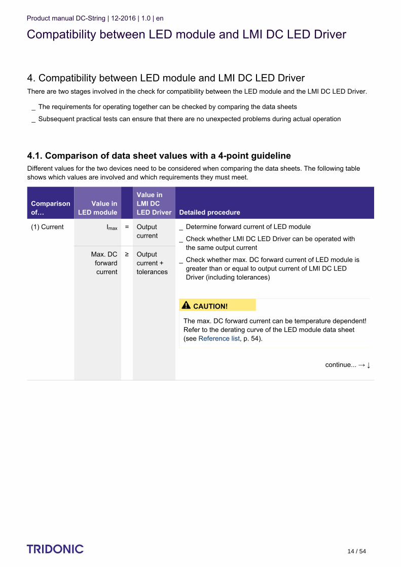
4. Compatibility between LED module and LMI DC LED DriverThere are two stages involved in the check for compatibility between the LED module and the LMI DC LED Driver.
4.1. Comparison of data sheet values with a 4-point guidelineDifferent values for the two devices need to be considered when comparing the data sheets. The following tableshows which values are involved and which requirements they must meet.
Comparisonof…
Value inLED module
Value inLMI DCLED Driver Detailed procedure
(1) Current Imax = Outputcurrent
continue... → ↓
Max. DCforwardcurrent
≥ Outputcurrent +tolerances
...
The requirements for operating together can be checked by comparing the data sheets_
Subsequent practical tests can ensure that there are no unexpected problems during actual operation_
Determine forward current of LED module_
Check whether LMI DC LED Driver can be operated withthe same output current
_
Check whether max. DC forward current of LED module isgreater than or equal to output current of LMI DC LEDDriver (including tolerances)
_
½ CAUTION!
The max. DC forward current can be temperature dependent!Refer to the derating curve of the LED module data sheet(see ).Reference list, p. 54

Product manual DC-String | 12-2016 | 1.0 | en
Compatibility between LED module and LMI DC LED Driver
c 15 / 54
Comparisonof…
Value inLED module
Value inLMI DCLED Driver Detailed procedure
(2) Voltage Min. forwardvoltage
> Min. outputvoltage
Max. forwardvoltage
< Max.outputvoltage
Min. forwardvoltage @ min.
dimlevel
> Min. outputvoltage
(3) LFcurrentripple
Max.permissibleLF current
ripple
≥ Output LFcurrentripple(<120Hz)
(4) Max.peak current
Max.permissible
peak current
> Max.outputcurrentpeak
...
Check whether voltage range of LED module iscompletely within the voltage range of LMI DC LED Driver
_
½ CAUTION!
!The forward voltage is temperature dependentRefer to the Vf/t diagram in the data sheet (see p Reference
).list, p. 54
I NOTICE
To ensure full dimming performance the forward voltage ofthe LED module at min. dim level must be greater than orequal to the min. output voltage of the LMI DC LED Driver.
Determine the forward voltage of the LED module atlowest dim level
_
In case there is no data available for the LED module atlowest dim level: take the min. forward voltage minus 20%as an approximation
_
Check whether the forward voltage of the LED module isgreater than or equal to the min. output voltage of the LMIDC LED Driver
_
Check whether max. permissible LF current ripple of LEDmodule is greater than or equal to output LF current rippleof LMI DC LED Driver
_
Check whether max. permissible peak current of LEDmodule is greater than max. output current peak of LMIDC LED Driver
_

Product manual DC-String | 12-2016 | 1.0 | en
Compatibility between LED module and LMI DC LED Driver
c 16 / 54
4.2. Application of the 4-point guidelineThe compatibility check with the 4-point guideline is shown here using two examples.
4.2.1. Example
Comparison data for LMI DC LED Driver
LMI DC LED Driver
Designation LMI 48V 350–700mA 20–42V FO Regular
Manufacturer TRIDONIC
Data sheet values of LMI DC LED Driver
Output current 500 mA
Output current tolerance ± 8%
Min. output voltage 20 V (1)
Max. output voltage 42 V (1)
Output LF current ripple ± 2%
Max. output current peak 600 mA
(1) Values at 500mA

Product manual DC-String | 12-2016 | 1.0 | en
Compatibility between LED module and LMI DC LED Driver
c 17 / 54
Comparison data for LED module
LED module
Designation Fictitious device
Manufacturer Other manufacturer
Data sheet values of LED module
Forward current 500 mA
Max. DC forward current 1,050 mA
Typ. forward voltage 33 V +/-10% (1)
Min. forward voltage 29.7 V (1)
Max. forward voltage 36.3 V (1)
Max. permissible LF current ripple 630 mA
Max. permissible peak current 1,500 mA
Power draw 16.4 W
(1) Values at 500mA
Questions
...
Are the two devices mutually compatible?_
Can the required luminous flux of 1,510 lm be achieved with this combination?_
Product manual DC-String | 12-2016 | 1.0 | en
Compatibility between LED module and LMI DC LED Driver
c 18 / 54
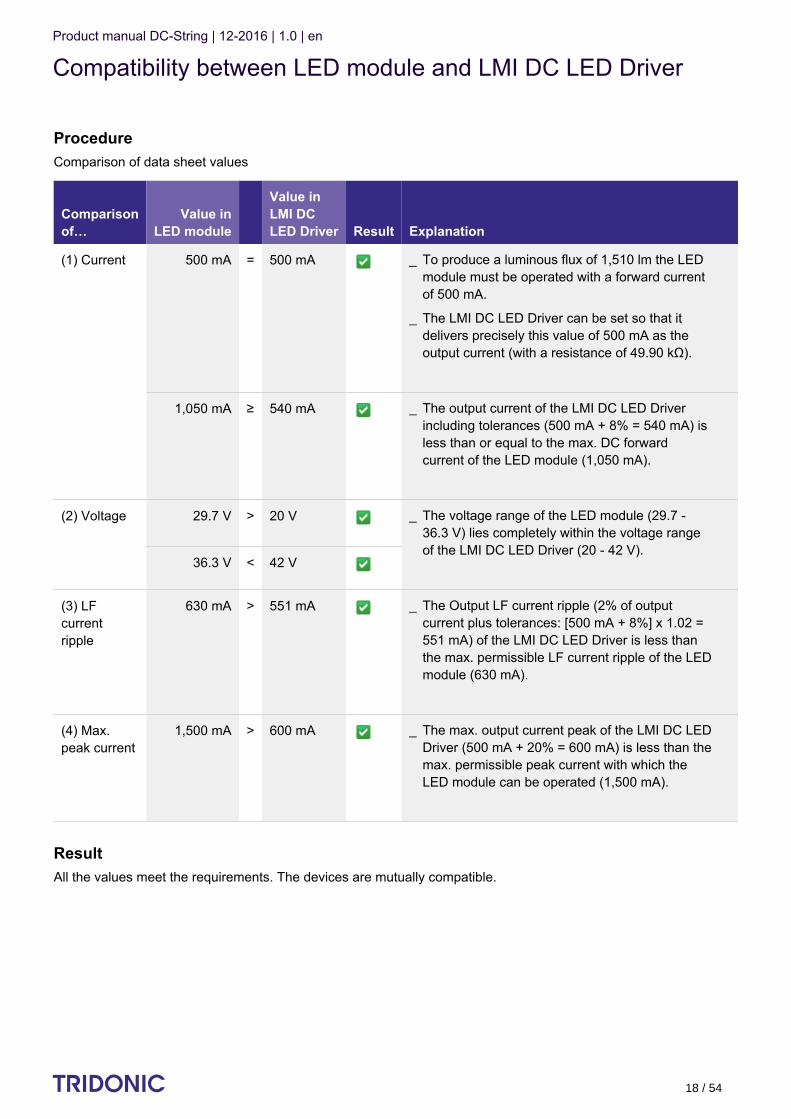
ProcedureComparison of data sheet values
Comparisonof…
Value inLED module
Value inLMI DCLED Driver Result Explanation
(1) Current 500 mA = 500 mA
1,050 mA ≥ 540 mA
(2) Voltage 29.7 V > 20 V
36.3 V < 42 V
(3) LFcurrentripple
630 mA > 551 mA
(4) Max.peak current
1,500 mA > 600 mA
ResultAll the values meet the requirements. The devices are mutually compatible.
...
To produce a luminous flux of 1,510 lm the LEDmodule must be operated with a forward currentof 500 mA.
_
The LMI DC LED Driver can be set so that itdelivers precisely this value of 500 mA as theoutput current (with a resistance of 49.90 kΩ).
_
The output current of the LMI DC LED Driverincluding tolerances (500 mA + 8% = 540 mA) isless than or equal to the max. DC forwardcurrent of the LED module (1,050 mA).
_
The voltage range of the LED module (29.7 -36.3 V) lies completely within the voltage rangeof the LMI DC LED Driver (20 - 42 V).
_
The Output LF current ripple (2% of outputcurrent plus tolerances: [500 mA + 8%] x 1.02 =551 mA) of the LMI DC LED Driver is less thanthe max. permissible LF current ripple of the LEDmodule (630 mA).
_
The max. output current peak of the LMI DC LEDDriver (500 mA + 20% = 600 mA) is less than themax. permissible peak current with which theLED module can be operated (1,500 mA).
_

Product manual DC-String | 12-2016 | 1.0 | en
Compatibility between LED module and LMI DC LED Driver
c 19 / 54
ProcedureComparison of data sheet values
ResultOne of the values meet the requirements. The devices are mutually compatible.does not not
...
Product manual DC-String | 12-2016 | 1.0 | en
Compatibility between LED module and LMI DC LED Driver
c 20 / 54
4.3. Practical testsPractical tests are used to ensure fault-free operation of the LED module and LMI DC LED Driver. The followingaspects must be checked.
4.3.1. Technical aspects
4.3.2. Visual aspects
4.3.3. ConditionsWhen conducting the tests the following conditions must be considered:
...
Transient behaviour_
Colour shift_
Connection during operation_
Parasitic capacitance_
Flickering_
Stroboscopic effect (video applications)_
Dimming behaviour_
Colour change/stability_
Luminous flux_
All tolerances_
Entire temperature range_
Different output voltage ranges (incl. no load)_
Entire dimming range_
Short circuit_
I NOTICE
If the values are slightly over or under the specified threshold values or if there are any other concerns orquestions please contact Technical Support: [email protected]

Product manual DC-String | 12-2016 | 1.0 | en
Standards and directives
c 21 / 54
4.4. Standards and directives4.4.1. Standards and directives for modulesThe following standards and directives were taken into consideration in designing and manufacturing the modules:
CE
Name Description
2006/95/EG Low-voltage directive: Directive relating to electrical equipment for use within certain voltage limits
2004/108/EG EMC directive: Directive relating to electromagnetic compatibility
RoHS
Name Description
2002/95/EC RoHS directive: Directive on the restriction of the use of certain hazardous substances in(1)
electrical and electronic equipment
(1) RoHS: Restriction of (the use of certain) hazardous substances
Safety
Name Description
DIN IEC 62031:2008 Safety requirements for LED modules
EN 60598-1:2008 und A11:2009 General requirements and tests for luminaires
EN 60598-2-2:1996 und A1:1997 Luminaires - Part 2. Special requirements; Main section 2: Recessed luminaires
EN 62471:2008 Photo-biological safety of lamps and lamp systems

Product manual DC-String | 12-2016 | 1.0 | en
Standards and directives
c 22 / 54
Safety and performance
Name Description
EN 61347-1:2009 General and safety requirements
EN 61347-2-13:2007 Special requirements for dc and ac powered electronic operating equipment forLED modules
EN 62384:2007 IEC 62384A1:2009
Operational requirements
Energy labelling
Name Description
EU Regulation No: 874/2012 "Energy labelling of electrical lamps and luminaires"
4.4.2. Standards and directives for LED DriverThe following standards and directives were taken into consideration in designing and manufacturing the LEDDriver:
EMI
Name Description
EN 55015 2008 Limit values measurement methods for radio interference properties of electricallighting equipment and similar electrical devices
EN 61000-3-2:2005 A1:2008 und A2:2009
Limit values for harmonic currents (equipment input current < 16 A per conductor)
EN 61000-3-3:2005 Limit values for voltage fluctuations and flicker in low-voltage systems for equipmentwith an input current < 16 A per conductor that are not subject to any special connection conditions
EN 61547:2001 EMC requirements(1)
(1) EMC: Electromagnetic compatibility

Product manual DC-String | 12-2016 | 1.0 | en
Standards and directives
c 23 / 54
Safety
Name Description
EN 50172 2005 Safety lighting systems
DALI
Name Description
IEC 62386-101:2009 General requirements, system
IEC 62386-102:2009 General requirements, controller
IEC 62386-207:2009 Special requirements, controller; LED modules
...
Product manual DC-String | 12-2016 | 1.0 | en
Installation
c 24 / 54
5. Installation
5.1. Guideline for installation The The guideline for installation can be taken fromLMI DC LED Driver devices were tested with severity level 2.
the ESD document.
5.1.1. Requirements for installationDepending on the installation situation for the LCU DC power supply, the LMI DC LED Driver and the LED-Module,the following requirements must be met:
5.2. Protection measures against damage
5.2.1. Mechanical stressLMI DC LED Driver contain electronic components that are sensitive to mechanical stress. Such stress should bekept to an absolute minimum. In particular the following mechanical stresses should be avoided as these may causeirreversible damage:
I NOTICE
EOS/ESD safety guidelinesThe device/module contains components that are sensitive to electrostatic discharge and may only be installed inthe factory and on site if appropriate EOS/ESD protection measures have been taken. No special measures needbe taken for devices/modules with enclosed casings (contact with the pc board not possible), just normalinstallation practice.Please note the requirements set out in the document EOS/ESD guidelines (Guideline_EOS_ESD.pdf) at:
http://www.tridonic.com/com/de/download/technical/Richtlinie_EOS_ESD_de.pdf_
http://www.tridonic.com/com/en/technical-docs.asp_
Sufficient distance to active conducting materials_
Sufficient strain relief when the LMI DC LED Driver cover is closed_
Sufficient cooling of the modules (the max. temperature at the tc point must not be exceeded)_
Unrestricted exit of light from the LED modules_
The LED module's push-in terminals allow easy wiring. They can be released via the trigger_
Pressure_
Drilling,_
Milling,_
Breaking,_
Sawing,_
and similar mechanical processing._

Product manual DC-String | 12-2016 | 1.0 | en
Installation
c 25 / 54
5.2.2. Compressive stressesThe components of the LMI DC LED Driver (circuit boards, electronic components etc.) are sensitive to compressivestresses. The components must not be exposed to compressive stresses.
...
Product manual DC-String | 12-2016 | 1.0 | en
Electrical Aspects
c 26 / 54
6. Electrical AspectsI NOTICE
The cabling, wiring and mounting for a LMI DC LED Driver and a LCU DC power supply varies depending on thedesign and manufacturer of the LED module.The following description should therefore not be viewed as comprehensive installation instructions but merely asimportant general information.
To obtain further information, proceed as follows:
Read the documentation provided by the lamp manufacturer. Follow the guidelines and instructions of thelamp manufacturer!
_
Observe all relevant standards. Follow the instructions given in the standards!_
½ WARNING!
Comply with the general safety instructions (see ) !General safety instructions, p. 5_
To avoid failures due to ground faults protect the wiring against mechanical loads from sharp-edged metalparts (e.g. cable penetrations, cable holders, metal frames, etc.
_
LMI DC LED Driver from Tridonic are protected for a maximum of 48 hour against overvoltage of up to 320V. Make sure that the LMI DC LED Driver is not exposed to overvoltages for long periods!
_
LCU DC power supply devices of the LCU DIM and LCU FO series from Tridonic have protection type IP 20.Comply with the requirements for this type of protection!
_
LMI DC LED Drivers don't have any protection._

Product manual DC-String | 12-2016 | 1.0 | en
Electrical Aspects
c 27 / 54
6.1. Wiring diagrams
6.1.1. Wiring diagram for DALI
The wiring diagram shows the connection between mains, LCU DC power supply, LMI DC LED Driver.
6.1.2. Wiring diagram for switchDIM
The wiring diagram shows the connection between mains, LCU DC power supply, LMI DC LED Driver.

Product manual DC-String | 12-2016 | 1.0 | en
Electrical Aspects
c 28 / 54
6.1.3. Connections on the LMI DC LED Driver and LCU DC power supply
Pin Connection
LCU Function earth
LCU ~ Power input 230 – 240 V AC
LCU ~ Power input 230 – 240 V AC
LCU DA(1) Control input for DALI / switchDIM
LCU DA(1) Control input for DALI / switchDIM
LMI/LED +LED TALEXXmodule STARK SLE GEN4
LMI/LED -LED TALEXXmodule STARK SLE GEN4
LCU/LMI 48V+ 48 V bus (polarity at the inputs of the LMI DC LED Driver does not matter)
LCU/LMI 48V- 48 V bus (polarity at the inputs of the LMI DC LED Driver does not matter)
LMI FO Potentiometer 2)
LMI FO Potentiometer 2)
1) Only for operation with LMI DC LED Driver and LCU DC power supply Only for LMI DC LED Driver with potentiometer terminal2)
...

Product manual DC-String | 12-2016 | 1.0 | en
Electrical Aspects
c 29 / 54
6.2. Function of the earth terminal
The earth connection is conducted as protection earth (PE). The LCU DC power supply can be earthed via earthterminal or metal housing (if device has metal housing). If the LCU DC power supply will be earthed, protectionearth (PE) has to be used. There is no earth connection required for the functionality of the LCU DC power supply.
Earth connection is recommended to improve following behaviour.
In general it is recommended to earth the LMI DC LED Driver if the LED module is mounted on earthed luminaireparts respectively heat sinks and thereby representing a high capacity against earth.
6.2.1. Mains transients at the LED outputThe transfer of mains transients to the LED output presents a problem for many LED driver topologies currently onthe market, and TRIDONIC devices may be affected.
Voltage peaks at the input of the LCU DC power supply may be transferred to the output of the LMI DC LED Driverwhere they lead to differences in potential between the LED output and earthed luminaire parts. These differencesin potential may result in flashovers if the insulation is inadequate or if the creepage and clearance distances are toosmall. Flashovers will cause the LED module to fail.
Earthing the LMI DC LED Driver attenuates voltage peaks and reduces the likelihood of flashovers. The precisedegree of attenuation depends on the capacitance of the LED module with respect to earth. Voltages at the outputof the LMI DC LED Driver are not higher than 450 V.
...
Electromagnetic interferences (EMI)_
LED glowing at standby_
Transmission of mains transients to the LED output_
I NOTICE
Irrespective of whether the LCU DC power supply is earthed or not, LED modules and LMI DC LED Driver mustbe insulated in accordance with the requirements of the luminaire protection class. Improved insulation of the LEDmodule can also reduce the likelihood of flashovers.
Product manual DC-String | 12-2016 | 1.0 | en
Electrical Aspects
c 30 / 54
6.3. Routing the wires
6.3.1. Tests
6.3.2. Insulation and dielectric strength testing of luminairesLCU DC power supply devices are sensitive to high-voltage transients. This must be taken into consideration whensubjecting luminaires to routine testing during manufacture.
According to IEC 60598-1 Annex Q (for information only!) and ENEC 303-Annex A, each luminaire should besubjected to an insulation test for 1 second at 500 V DC. The test voltage is applied between the linkedphase/neutral conductor terminal and the protective earth terminal. The insulation resistance must be at least 2MOhm.
As an alternative to measuring the insulation resistance, IEC 60598-1 Annex Q describes a dielectric strength test at1500 V AC (or 1.414 x 1,500 V DC). To avoid damaging electronic control gear, this dielectric strength test shouldbe performed exclusively for type testing. This test should certainly not be used for routine testing.
6.3.3. Type testingType testing of the luminaire is performed according to IEC 60598-1 Section 10.The wiring for protection class 1 luminaires is tested at a voltage of 2xU + 1,000 V. In order not to overload thecontrol gear all the inputs and outputs of the control gear are connected to one another.U is used for measuring the voltage for luminaires with control gear with U > 250 V:out outFor U 480 V the voltage for the type test is 2000 V. (Routine testing is always performed at 500 V DC)out
I NOTICE
The performance of the prescribed tests and compliance with relevant standards are the responsibility of theluminaire manufacturer.The following descriptions merely indicate the most important tests and are no substitute for a full research of therelevant standards.
I NOTICE
Tridonic recommends performing an insulation test because a dielectric strength test may damage the deviceirreparably.

Product manual DC-String | 12-2016 | 1.0 | en
Electrical Aspects
c 31 / 54
6.3.4. Wiring between LCU and LMI
Wiring guidelines
Hot plug-in of LMI DC LED Driver
6.3.5. Wiring between LMI and LED
Wiring guidelines
Wiring the plug-in terminal
The 48 V cables should be run separately from the mains connections and mains cables to ensure goodEMC conditions.
_
The 48 V DC output wiring should be kept as short as possible to ensure good EMC.The max. secondarycable length is 30 m (60 m circuit) till beginning of a grounded metal track light.
_
If track light is not grounded or made of plastic, cable length including track light is 30 m._
Inside the track light cable length is limited by voltage drop that last LMI 48V in the track light is still suppliedwith minimum 46 V.
_
Secondary switching is not permitted. It is allowed to add or remove one DC/DC-LED Driver during operation._
Hot plug-in is supported for LMI DC LED Driver._
I NOTICE
The wiring procedure is device specific. Further information about wiring, wire cross sections and the length ofstripped off insulation can be found in the data sheet.
The wiring between LMI and LED should be run separately from the mains connections and mains cables toensure good EMC conditions.
_
The LED wiring should be kept as short as possible to ensure good EMC. The max. secondary cable lengthis 2 m (4 m circuit).
_
The LMI DC LED Driver has no inverse-polarity protection on the secondary side. Wrong polarity candamage LED modules with no inverse-polarity protection.
_
Use solid wire or stranded wire with the correct cross-section_
Strip off correct length of insulation; you may need to twist the tool slightly_
If stranded wire is used: push onto the terminal from above to be able to insert the wire_
Insert the bare end into the terminal_

Product manual DC-String | 12-2016 | 1.0 | en
Electrical Aspects
c 32 / 54
Detaching the plug-in terminal
...
Push onto the terminal from above to release the wire_
Pull out the wire at the front_
Product manual DC-String | 12-2016 | 1.0 | en
Electrical Aspects
c 33 / 54
6.4. Maximum loading of circuit breakers
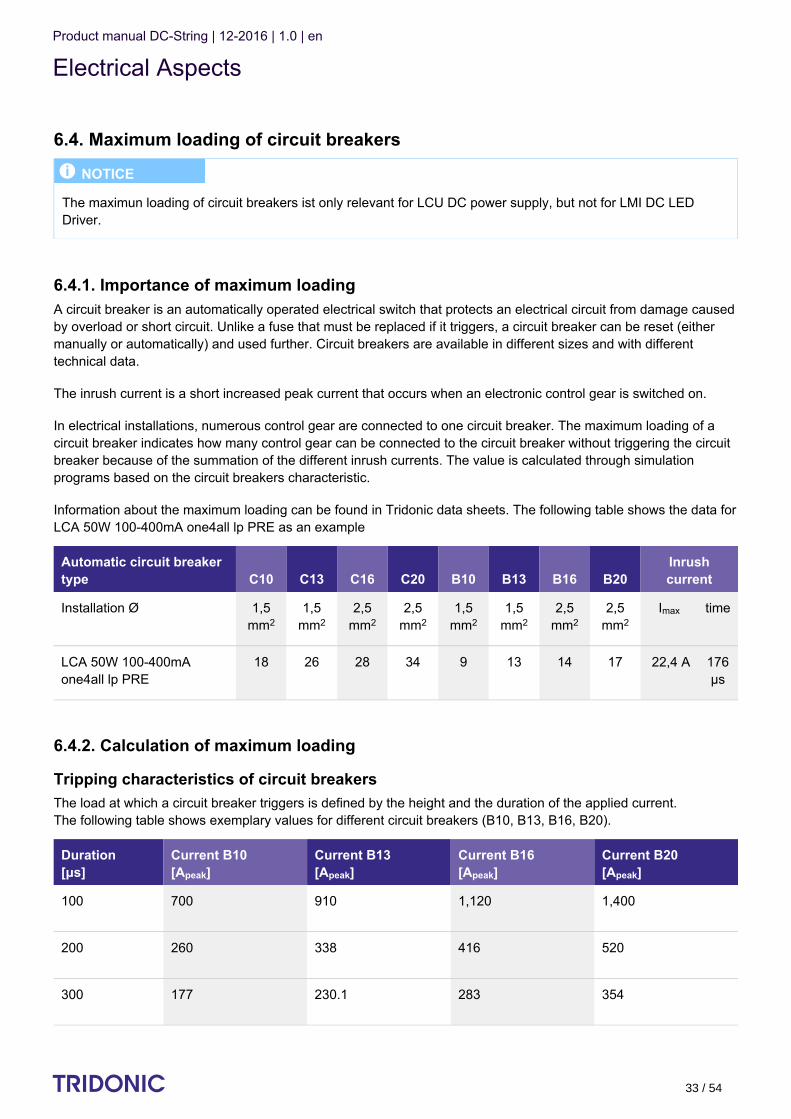
6.4.1. Importance of maximum loadingA circuit breaker is an automatically operated electrical switch that protects an electrical circuit from damage causedby overload or short circuit. Unlike a fuse that must be replaced if it triggers, a circuit breaker can be reset (eithermanually or automatically) and used further. Circuit breakers are available in different sizes and with differenttechnical data.
The inrush current is a short increased peak current that occurs when an electronic control gear is switched on.
In electrical installations, numerous control gear are connected to one circuit breaker. The maximum loading of acircuit breaker indicates how many control gear can be connected to the circuit breaker without triggering the circuitbreaker because of the summation of the different inrush currents. The value is calculated through simulationprograms based on the circuit breakers characteristic.
Information about the maximum loading can be found in Tridonic data sheets. The following table shows the data forLCA 50W 100-400mA one4all lp PRE as an example
Automatic circuit breakertype C10 C13 C16 C20 B10 B13 B16 B20
Inrushcurrent
Installation Ø 1,5mm2
1,5mm2
2,5mm2
2,5mm2
1,5mm2
1,5mm2
2,5mm2
2,5mm2
Imax time
LCA 50W 100-400mAone4all lp PRE
18 26 28 34 9 13 14 17 22,4 A 176μs
6.4.2. Calculation of maximum loading
Tripping characteristics of circuit breakersThe load at which a circuit breaker triggers is defined by the height and the duration of the applied current. The following table shows exemplary values for different circuit breakers (B10, B13, B16, B20).
Duration[μs]
Current B10[A ]peak
Current B13[A ]peak
Current B16[A ]peak
Current B20[A ]peak
100 700 910 1,120 1,400
200 260 338 416 520
300 177 230.1 283 354
I NOTICE
The maximun loading of circuit breakers ist only relevant for LCU DC power supply, but not for LMI DC LEDDriver.

Product manual DC-String | 12-2016 | 1.0 | en
Electrical Aspects
c 34 / 54
400 145 188.5 232 290
500 122 158.6 195 244
600 110 143 176 220
700 102 132.6 163 204
800 97 126.1 155 194
900 93 120.9 149 186
1000 90 117 144 180
The combination of both parameters can also be displayed graphically. This results in the tripping characteristic fora certain circuit breaker.
Current [A]
Duration [μs]
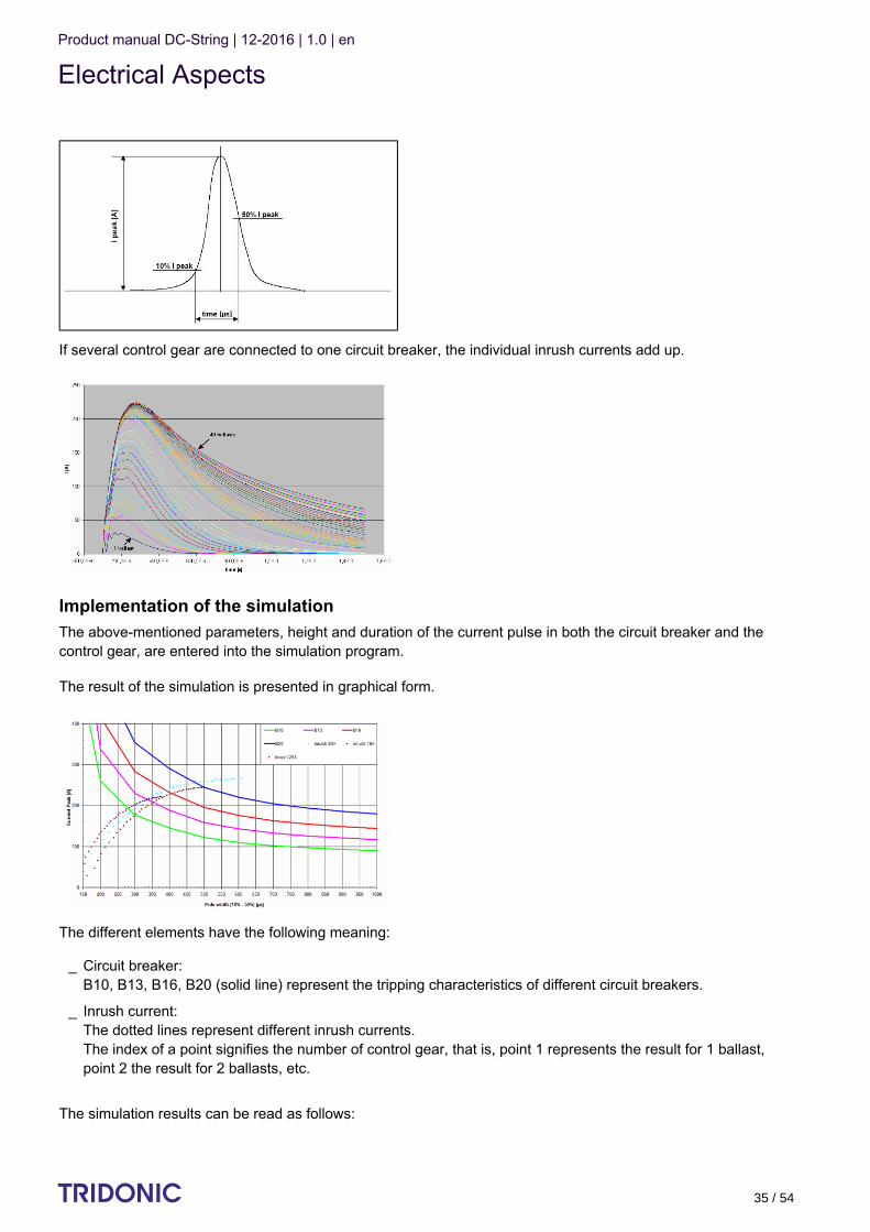
Calculation of the inrush currentThe inrush current of a control gear is also defined by its duration and its height. The duration is typically measuredas the time between 10% of maximum current (ascending) and 50% of maximum current (descending).
The following illustration shows the inrush current of a single control gear:
I NOTICE
Information about the specific tripping characteristics of a circuit breaker must be requested from the respectivemanufacturer !
Product manual DC-String | 12-2016 | 1.0 | en
Electrical Aspects
c 35 / 54
If several control gear are connected to one circuit breaker, the individual inrush currents add up.
Implementation of the simulationThe above-mentioned parameters, height and duration of the current pulse in both the circuit breaker and thecontrol gear, are entered into the simulation program.
The result of the simulation is presented in graphical form.
The different elements have the following meaning:
The simulation results can be read as follows:
Circuit breaker:B10, B13, B16, B20 (solid line) represent the tripping characteristics of different circuit breakers.
_
Inrush current:The dotted lines represent different inrush currents.The index of a point signifies the number of control gear, that is, point 1 represents the result for 1 ballast,point 2 the result for 2 ballasts, etc.
_

Product manual DC-String | 12-2016 | 1.0 | en
Electrical Aspects
c 36 / 54
The following example shows the maximum number of control gear at four different circuit breakers:
...
The crossing of the two lines shows the maximum value for the selected combination of circuit breaker andinrush current.
_
The index of the point at this maximum value shows the max. number of ballasts._
max. 5 devices at circuit breaker B10 (green tripping characteristic)_
max. 7 devices at circuit breaker B13 (pink tripping characteristic)_
max. 9 devices at circuit breaker B16 (red tripping characteristic)_
max. 12 devices at circuit breaker B20 (blue tripping characteristic)_
I NOTICE
The results of different simulations can only be compared if all of the relevant factors are the same. The followingpoints can influence the results:
Tripping characteristic used for the circuit breakers_
Definition used for the duration of the inrush current (Tridonic: 10-50 %)_
Gear used for the measurement of the inrush current (especially important: Which electrolytic capacitor isinstalled in the control gear?)
_
Considering a safety buffer (Tridonic: +20 % for the electrolytic capacitor )_
Considering different system impedances_
Switch-on point used: should always be at max. input voltage_
Adopted cable lengths and cable data (Tridonic: Cable length 40 cm; Resistivity: 0.0172 ohm * mm2 / m;inductance: 5nH / cm; terminal resistance: 2mOhm)
_
The modeling of the control gear is performed from the input to the bus voltage electrolytic capacitor . Forinductance the saturation values must be used.
_

Product manual DC-String | 12-2016 | 1.0 | en
Functions
c 37 / 54
1.
2.
7. Functions
7.1. corridorFUNCTION V2 (combination of LCU DIM and LMI DIM only)
7.1.1. DescriptionThe corridorFUNCTION enables the illuminance to be linked to the presence or absence of people. A conventionalrelay motion sensor is connected. The luminous intensity is increased when a person enters the room. When theperson leaves the room the motion sensor switches off after a certain delay and the luminous intensity isautomatically reduced.
The corridorFUNCTION is particularly beneficial in applications in which light is needed round the clock for safetyreasons, for example in public buildings, large apartment complexes, car parks, pedestrian underpasses andunderground railway stations. Since the luminous intensity only has to be increased when there is a demand for lightthe corridorFUNCTION offers effective lighting management and helps saving energy and costs. Another benefit ofthe corridorFUNCTION is the enhanced convenience of automatic lighting control.
Profile settings:Standard profile for activating via 230V on the interface terminal DA/N - DA/L for 5 minutes is "Never off"
The control gear have different profiles so they can provide the best possible performance in a range of conditions.The profiles are defined by a series of values:
Fade-in time: the time that starts as soon as the presence of a person is detected. During the fade-in time theluminous intensity is faded up to the presence value (default: 0s).
Run-on time: the time that starts as soon as the presence of a person is no longer detected. If the presence of aperson is detected again during the run-on time the run-on time is restarted from zero. If no presence isdetected during the run-on time the fade time is started as soon as the run-on time expires.
I NOTICE
The corridorFUNCTION and switchDIM only work broadcast via LCU DC power supply to all LMI DC LED drivers.
½ CAUTION!
To ensure correct operation a sinusoidal mains voltage with a frequency of 50 Hz or 60 Hz is required at thecontrol input.Special attention must be paid to achieving clear zero crossings. Serious mains faults may impair the operation ofswitchDIM and corridorFUNCTION.

Product manual DC-String | 12-2016 | 1.0 | en
corridorFUNCTION V2
c 38 / 54
3.
4.
5.
6.
Fade time: the time during which the luminous intensity is faded from the presence value to the absence value(default: 30s).
Switch off delay: the time during which the absence value is held before the lighting is switched off. Dependingon the profile selected the switch-off delay may have different values or may not be defined (default: "NeverOff").
Absence value: the luminous intensity when there is no person present (default: 10%).
Presence value: the luminous intensity when persons are present (default: 100%).
Variable switch-off timesThe profiles and their values can be freely adjusted. The values can be adjusted via a connection to a DALI bus onthe LCU DC power supply.
7.1.2. Installation
Requirements:
Procedure:
The control gear is correctly installed in the luminaire and cabled on the power supply side_
A motion sensor is installed in the lighting system_
The motion sensor is connected to the control gear_
Connect the neutral conductor (N) to terminal DA/N on the control gear_
Connect the output of the motion sensor (switched phase) to terminal DA/L on the control gear_

Product manual DC-String | 12-2016 | 1.0 | en
corridorFUNCTION V2
c 39 / 54
Wiring versions:
Benefits:Control can be changed at any time to a digital control signal (DSI or DALI) without having to change the luminaireor provide an additional control line
½ CAUTION!
Use conventional relay motion sensors!Electronic motion sensors (Triac) are not suitable because of their technical design.
½ CAUTION!
Do not use glow switches!Glow switches may affect the control.

Product manual DC-String | 12-2016 | 1.0 | en
corridorFUNCTION V2
c 40 / 54
...
½ CAUTION!
Make sure that the control line (L') of the motion sensor is connected to terminal DA/L and the neutral conductor(N) to terminal DA/N.
½ CAUTION!
For five-pole wiring the neutral conductor must be connected to DA/N. This prevents 400 V being applied between adjacent terminals if a different phase is used for the control input.
I NOTICE
For large installations, supply to the control gear may be split among several phases (L1, L2, L3).Any phase can be used for the control input .Any number of motion sensors can be connected in parallel.

Product manual DC-String | 12-2016 | 1.0 | en
corridorFUNCTION V2
c 41 / 54
7.1.3. Commissioning
Activating the corridorFUNCTION
Procedure by means of the mains voltageActivating the corridorFUNCTION is simple. If an a.c. voltage of 230 V is applied to the digital interface of the controlgear for a period of at least 5 minutes the control gear detects the corridorFUNCTION and automatically activates it.Activation is required only once per device.There are three procedures for activating by means of the mains voltage. The requirements are the same in eachcase.
Requirements:
Procedure Version 1:
Procedure Version 2:
Procedure Version 3: Only possible if the motion sensor offers a manual override option
Procedure via the masterCONFIGURATORThe corridorFUNCTION can also be activated via the masterCONFIGURATOR.
Further information can be found in the masterCONFIGURATOR manual (see ).Reference list, p. 54
The control gear is correctly installed in the luminaire_
Input voltage is applied_
A motion sensor is connected to information DA/N or DA/L_
Remain in the activation range of the motion sensor for more than 5 minutes→ The motion sensor detects movement and switches on→ The corridorFUNCTION is activated automatically after 5 minutes→ The light value switches to presence level (default: 100%)
_
Set the run-on time on the motion sensor to a value greater than 5 minutes_
Remain in the activation range of the motion sensor for a short time→ The motion sensor detects movement and switches on→ The corridorFUNCTION is activated automatically after 5 minutes→ The light value switches to presence value (default: 100%)
_
Reset the run-on time of the motion sensor to the required value_
Set the slide switch on the motion sensor to the "Never-Off" function_
Wait 5 minutes→ The corridorFUNCTION is activated automatically after 5 minutes→ The light value switches to presence value (default: 100%)
_
Reset the slide switch on the motion sensor to the "automatic" function_
Product manual DC-String | 12-2016 | 1.0 | en
corridorFUNCTION V2
c 42 / 54
Deactivating the corridorFUNCTIONIf the corridorFUNCTION is activated the control gear is controlled only by motion. To operate the control gear viaDALI, DSI or switchDIM the corridorFUNCTION must be deactivated.
Procedure via mains
Procedure via DALI/DSI
Procedure via masterCONFIGURATORIf the corridorFUNCTION was activated via the masterCONFIGURATOR it can be deactivated as follows:
Adjusting the values of the corridorFUNCTIONThe values of the corridorFUNCTION can be individually adjusted. The values are set via a DALI USB on the busand by entering special DALI commands via the masterCONFIGURATOR.
Further information can be found in the masterCONFIGURATOR manual (see ).Reference list, p. 54
...
Connect mains voltage push button to the terminal marked DA/L_
Connect neutral conductor to the terminal marked DA/N_
Press the push button 5 times within 3 seconds_
Send 5 DALI or DSI commands within 3 seconds to the control gear_
Send 5 DALI or DSI commands within 3 seconds to the control gear_

Product manual DC-String | 12-2016 | 1.0 | en
DALI
c 43 / 54
7.2. DALI (LCU DIM only)
7.2.1. Description
DALI standard
DALI (Digital Addressable Lighting Interface) is an interface protocol for digital communication between electroniclighting equipment.
The DALI standard was developed by Tridonic together with renowned manufacturers of operating and controlequipment. Today, these manufacturers belong to the DALI Activity Group which promotes the use and furtherdevelopment of DALI.
The DALI standard is defined in IEC 62386. A test procedure standardised by the DALI Activity Group ensurescompatibility between products from different manufacturers. Tridonic products have undergone this test and meetall the requirements. This is indicated by the logo of the DALI Activity Group on the device.
The agreement by the lighting industry to adopt a common protocol has opened up a virtually unlimited number ofoptions. With the right choice of individual DALI components an extremely wide range of requirements can be met,from operating a simple light switch to lighting management systems for entire office complexes with thousands oflight sources.
DALI in ActionDALI offers a lot of possibilities:
Technical data of a DALI line:
I NOTICE
LCU DIM devices support the new DALI standard V2 (according to EN 62386-102).
DALI line: 64 control gear can be grouped to a line_
DALI groups: Every control gear can be attributed into 16 groups_
Addressability: All control gear are individually addressable_
Grouping: Possible without complicated rewiring_
Programmability: Individual programmability makes it possible to use functions which transcend the DALIstandard
_
Monitoring: Easily possible thanks to status feedback_
Wiring: Simple wiring with five pole standard cables and a cable length of max. 300 metres_
Wiring: Polarity-free control lines can be used for mains and control lines_
Wiring: Multiple wiring possibilities (star, series and mixed wiring)_
Unaffected by interruptions: All luminaires receive the same, unaffected digital signal and dimming level_
Similar light level from first to last luminaire_
DALI voltage: 9.5 V - 22.4 DC_
Maximum DALI system current: max. 250 mA_
Data transfer rate: 1200 Baud_

Product manual DC-String | 12-2016 | 1.0 | en
DALI
c 44 / 54
7.2.2. Commissioning
Further information can be found in the DALI Handbook (see ).Reference list, p. 54
eDeD ("enhanced DALI") offers extended DALI commands. They can be used to activate specific commands of thecontrol gear. The masterCONFIGURATOR software works with eD commands. These commands are Tridonicspecific. They are not part of the DALI standard and are not publicly available.
...
Data transfer rate: 1200 Baud_
Maximum line length: up to 300 m (for 1,5 mm )2_
I NOTICE
If the corridorFUNCTION is activated the control gear is controlled only by motion. To operate the control gear viaDALI, DSI or switchDIM the corridorFUNCTION must be deactivated.
Product manual DC-String | 12-2016 | 1.0 | en
DSI
c 45 / 54
7.3. DSI (LCU DIM only)
7.3.1. DescriptionDSI (Digital Serial Interface) enables DSI control gear to be controlled. The DSI line can be wired separately via atwo-core cable or together with the mains cable in a five-core cable. Communication is not impaired by the mainscable. In contrast to DALI, there is no individual addressing of the ballasts with DSI.
DSI offers a series of benefits:
The main benefits of DSI are the optimisation of energy consumption of extensive groups of luminaires (e.g. insports stadiums and factories).
7.3.2. Commissioning
Further information can be found in the DALI Handbook (see ). Reference list, p. 54
...
Expansion options via submodules, for example in combination with daylight control or additional switchmodules
_
Wiring: Simple wiring with five pole standard cables and line length of up to 250 metres_
Wiring: Polarity-free control lines can be used for mains and control lines_
Wiring: Multiple wiring possibilities (star, series and mixed wiring)_
Unaffected by electrical interference_
Uniform light level from the first to the last light source_
reverse polarity protected connection: can be connected with any polarity_
I NOTICE
If the corridorFUNCTION is activated the control gear is controlled only by motion. To operate the control gear viaDALI, DSI or switchDIM the corridorFUNCTION must be deactivated.

Product manual DC-String | 12-2016 | 1.0 | en
switchDIM
c 46 / 54
7.4. switchDIM (LCU DIM only)
7.4.1. DescriptionWith the switchDIM function it is possible to use the mains voltage as a control signal.The phase of a simple standard mains voltage push button is connected to the terminal marked DA/L and theneutral conductor is connected to the terminal marked DA/N.
Using the function is easy and convenient:
switchDIM is therefore a very simple form of lighting management. It also has a positive effect on material andlabour costs.
The device has a switchDIM memory function. This is used, among other things, for storing the last dimming valuein the event of interruptions in the power supply.When power returns, the LED is automatically restored to its previous operating state and dimmed to the last value.
7.4.2. Installation
Wiring variantsThere are two options for installing switchDIM: four-pole and five-pole wiring
A short press (50-600 ms) switches the device on or off_
A long press (> 600 ms) fades the connected LCU DC power supply alternately up and down (between 5 and100%).
_
½ CAUTION!
Glow switches are not approved for controlling switchDIM.Glow switches may cause the LCU DC power supply to spontaneously switch on or off or make sudden changesin the dimming value.
½ CAUTION!
To ensure correct operation a sinusoidal mains voltage with a frequency of 50 Hz or 60 Hz is required at theterminal.Special attention must be paid to achieving clear zero crossings. Serious mains faults may impair the operation ofswitchDIM and corridorFUNCTION.
½ CAUTIONS!
A maximum number of 25 operating devices per switchDIM system should not be exceeded.If you have more devices please use DALI or DSI.

Product manual DC-String | 12-2016 | 1.0 | en
switchDIM
c 47 / 54
Four-pole wiring
Configuration:
Phase (L), neutral (N), earth (PE), control line (L')
Benefits:No need for a control line thanks to bridging terminal 8 and the N-connection of the luminaire
Five-pole wiring
Configuration:
Phase (L), neutral (N), earth (PE), control line (L), neutral (N)
Benefits:Control can be changed at any time to a digital control signal (DSI or DALI) without having to change the luminaireor provide an additional control line

Product manual DC-String | 12-2016 | 1.0 | en
switchDIM
c 48 / 54
...
½ CAUTION!
For five-pole wiring the neutral conductor must be connected to DA/N. This prevents 400 V being applied between adjacent terminals if a different phase is used for the control input.
Product manual DC-String | 12-2016 | 1.0 | en
switchDIM
c 49 / 54
7.4.3. Commissioning
Using the switchDIM functionswitchDIM is operated by the mains voltage push button.
Procedure:
Synchronising devicesIf the devices in a system do not operate synchronously the devices must be synchronised, i.e. put in the samestatus (on/off).
Procedure:
Changing the fading timeThe default value for the fading time is approx. 3 seconds. It can be changed to approx. 6 seconds.
Procedure:
Switching the LCU DC power supply to automatic mode In automatic mode the device detects which control signal (DALI, DSI, switchDIM, etc.) is connected and
automatically switches to the corresponding operating mode.
Procedure:
...
I NOTICE
If the corridorFUNCTION is activated the LCU DC power supply is controlled only by motion. To operate the LCUDC power supply via DALI, DSI or switchDIM the corridorFUNCTION must be deactivated.
Switch the device on/off by briefly actuating the push button or_
Dim the device by holding down the push button_
Hold down the push button for 10 seconds→ All devices will be synchronised to the same status→ LEDs will will be set to a uniform light value (approx. 50%) → The fading time will be set to it default value (approx. 3 seconds)
_
Hold down the push button for 20 seconds→ After 10 seconds: all devices will be synchronised to the same status→ After 20 seconds: a fading time of approx. 6 seconds will be set→ LEDs will be set to a uniform light value (approx. 100%)
_
Press the push button 5 times within 3 seconds_
Product manual DC-String | 12-2016 | 1.0 | en
Constant Light Output
c 50 / 54
7.5. Constant Light Output (LMI DIM only)
7.5.1. DescriptionThe light output of an LED module reduces over the course of its life. The Constant Light Output functioncompensates for this natural decline by constantly increasing the output current of the LED driver throughout its life.As a results, a virtually uniform light output is achieved at all times.
For configuration purposes the expected module-specific values for lifetime and residual luminous flux must bespecified. The output current is then controlled automatically on the basis of these values. The LED driver typically starts with an output current ("Required Intensity") that corresponds to the expectedresidual luminous flux and calculates the increase in the value on the basis of the anticipated lifetime.
If the OTL function is enabled, visual feedback is given as soon as the LED exceeds the expected LED lamp life. Ifthe expected LED lamp life is exceeded, the luminaire flashes for 2 seconds after being switched on.
7.5.2. Commissioning
Procedure via the masterCONFIGURATOR
Activating the Constant Light Output function
Activating the Over the Lifetime function
I NOTICE
To be able to adjust the parameters "Required intensity", "LED burning hours" and "Expected LED life" the"Advanced settings" must be activated. Further information can be found in the masterCONFIGURATOR manual (see ).Reference list, p. 54
Open dialog box "Tridonic-specific configuration"_
Click tab "CLO and OTL"_
Set drop-down menu "Constant intensity" to "enabled"_
Click "save"→ Changes are saved
_
Open dialog box "Tridonic-specific configuration"_
Click tab "CLO und OTL"_
Set drop-down menu "Visual feedback" to "enabled"_
Click "save"→ Changes are saved
_
Product manual DC-String | 12-2016 | 1.0 | en
Constant Light Output
c 51 / 54
Setting Required intensity and Expected LED life
Transferring existing values to a new control gearIf a control gear is replaced the existing parameter values can be transferred to the new control gear.
Replacing the LED moduleIf an LED module is replaced the parameter "LED burning hours" must be set to "0".
Further information can be found in the masterCONFIGURATOR manual (see ).Reference list, p. 54
...
Open dialog box "Tridonic-specific configuration"_
Click tab "CLO and OTL"_
Enter values in input fields "Required intensity" and "Expected LED life"_
Click "save"→ Changes are saved
_
Chose a control gear that is in the same room as the new control gear_
Open dialog box "Tridonic-specific configuration"_
Click tab "CLO and OTL"_
Note down the values for "Required intensity", "LED burning hours" and "Expected LED life"_
Close dialog box "Tridonic-specific configuration"_
Chose the new control gear_
Open dialog box "Tridonic-specific configuration"_
Click tab "CLO and OTL"_
Take the noted values and enter them in the input fields "Required intensity", "LED burning hours" and"Expected LED life"
_
Click "save"→ Changes are saved
_
Open dialog box "Tridonic-specific configuration"_
Click tab "CLO and OTL"_
Delete value from input field "LED burning hours"→ CLO function is automatically restarted→ Changes are saved
_

Product manual DC-String | 12-2016 | 1.0 | en
Intelligent Temperature Guard
c 52 / 54
7.6. Intelligent Temperature Guard
7.6.1. DescriptionLCU DC power supply devices have a special overtemperature protection. It works as follows:
In the event of overtemperature (approx. 5-10 °C above t max), the output of the LCU DC power supply switchescoff and on three times. Doing so, the device will blink three times.
Afterwards, the device checks every 30 seconds whether there is still overtemperature.
...
½ WARNING!
The T temperature is the maximum permitted in terms of safety.cOperating the control gear above the permitted T temperature is not compliant with relevant standards.cThe Intelligent Temperature Guard function does not replace the proper thermal design of the luminaire and doesnot enable the lighting to operate for lengthy periods of time in impermissible ambient temperatures.
If this is the case, the procedure is repeated and the output is again switched off and on three times_
If this is no longer the case, normal operation is resumed._

Product manual DC-String | 12-2016 | 1.0 | en
Power-up Fading
c 53 / 54
7.7. Power-up Fading (combination of LCU DIM and LMI DIM only)
7.7.1. DescriptionThe power-up fading function offers the opportunity to realise a soft start. The soft start will be applied at turning onthe mains and at starts by switchDIM. The function is programmed as a DALI fade time in the range from 0.7 to 16seconds and dims in the selected time from 0% to the power-on level.
By factory default power-up fading is not active (0 seconds).
7.7.2. Commissioning
Procedure via the masterCONFIGURATOR
Further information can be found in the masterCONFIGURATOR manual (see ). Reference list, p. 54
...
Open dialog box "Tridonic-specific configuration"_
Click tab "Power-up Fading"_
Choose value from drop-down menu "Power-up Fading"_
Click "save"→ Changes are saved
_

Product manual DC-String | 12-2016 | 1.0 | en
Reference list
c 54 / 54
8. Reference list
8.1. Additional information
8.2. Downloads
8.3. Technical data
Web page Dimming series (LMI DC LED Driver DIM and LCU DC power supply DIM): http://www.tridonic.com/com/en/products/led-dc-string-dimming.asp
_
Web page Fixed output series (LMI DC LED Driver FO and LCU DC power supply FO): http://www.tridonic.com/com/en/products/led-dc-string-fixed-output.asp
_
Data sheets: Go to above web page link and click "Products" > "Downloads" > "Data sheet"_
Data sheets DC-String: http://www.tridonic.com/com/en/products/led-dc-string.asp_
Leaflet DC-String: http://www.tridonic.com/com/en/download/brochures/Leaflet_DC-String_EN_web.pdf_
DALI manual: http://www.tridonic.com/com/en/download/technical/DALI-manual_en.pdf_
Documentation masterCONFIGURATOR: http://www.tridonic.com/com/en/download/Manual_masterConfigurator_en.pdf
_
Leaflet ready2mains: http://www.tridonic.com/com/en/download/brochures/Leaflet_ready2mains_EN_web.pdf_
Webpage corridorFUNCTION: http://www.corridorfunction.com/corridorFUNCTION/index.html_
DC-String Video animation: https://www.youtube.com/watch?v=rZgKPLTZ3jY_
Tridonic software: http://www.tridonic.com/com/en/software.asp_
Download masterCONFIGURATOR: http://www.tridonic.com/com/de/software-masterconfigurator.asp_
Data sheets: http://www.tridonic.com/com/en/data-sheets.asp_
Company certificates: http://www.tridonic.com/com/en/company-certificates.asp_
Environmental declarations: http://www.tridonic.com/com/en/environmental-declarations.asp_
LED/lamp matrix: http://www.tridonic.com/com/en/lamp-matrix.asp_
Operating instructions: http://www.tridonic.com/com/en/operating-instructions.asp_
Other technical documents: http://www.tridonic.com/com/en/technical-docs.asp_
Tender text: http://www.tridonic.com/com/en/tender.asp_
Declarations of conformity: Available documents are found on each product page of our website in the"Certificates" tab for the specific product, www.tridonic.com/com/en/products.asp
_