LED Light Bar Hookup - learn.sparkfun SMD LEDs, which are spaced by about 1.07". For mounting...
12
LED Light Bar Hookup a learn.sparkfun.com tutorial Available online at: http://sfe.io/t133 Contents Introduction Hardware Overview Assembly Tips Example Circuits Resources and Going Further Introduction LED Light Bars are a super-easy way to add some extra- bright and colorful illumination to your project. Each Light Bar is essentially a set of three super-bright 5050-size LEDs. They’re offered in a variety of colors including white , red , blue , and green (note: the blue and green light bars are an older version, they look different but can still be connected the same way). While these bars are very simple devices, they do have a few quirks when it comes to using them. Like the fact that their nominal operating voltage is 12V. In this tutorial we’ll go over some of the Page 1 of 12
Transcript of LED Light Bar Hookup - learn.sparkfun SMD LEDs, which are spaced by about 1.07". For mounting...

LED Light Bar Hookup a learn.sparkfun.comtutorial
Available online at: http://sfe.io/t133
Contents
IntroductionHardware OverviewAssembly TipsExample CircuitsResources and Going Further
Introduction
LED Light Bars are a super-easy way to add some extra-bright and colorful illumination to yourproject. Each Light Bar is essentially a set of three super-bright 5050-size LEDs. They’re offered ina variety of colors including white, red, blue, and green (note: the blue and green light bars are anolder version, they look different but can still be connected the same way).
While these bars are very simple devices, they do have a few quirks when it comes to using them.Like the fact that their nominal operating voltage is 12V. In this tutorial we’ll go over some of the
Page 1 of 12
important specifications of these LED Light Bars. Then we’ll dive into some example circuits thatcan help you get the most of these nifty little LED assemblies.
Suggested Reading
Here are some concepts and tutorials you should be familiar with before diving into this tutorial:
Light Emitting Diodes (LEDs) – This tutorial will help familiarize you with the LED lexicon.Polarity – These LED Light Bars are polarized. Don’t mix up the + and -!Working with Wire – It’ll be good to know how to strip, tin, and splice wire.Pulse Width Modulation (PWM) – PWM is a popular method to dim LEDs with a digital signal.What is an Arduino? – One of our examples will an Arduino, a beginner-friendlyprogrammable microcontroller, to help dim the Light Bars.
Hardware Overview
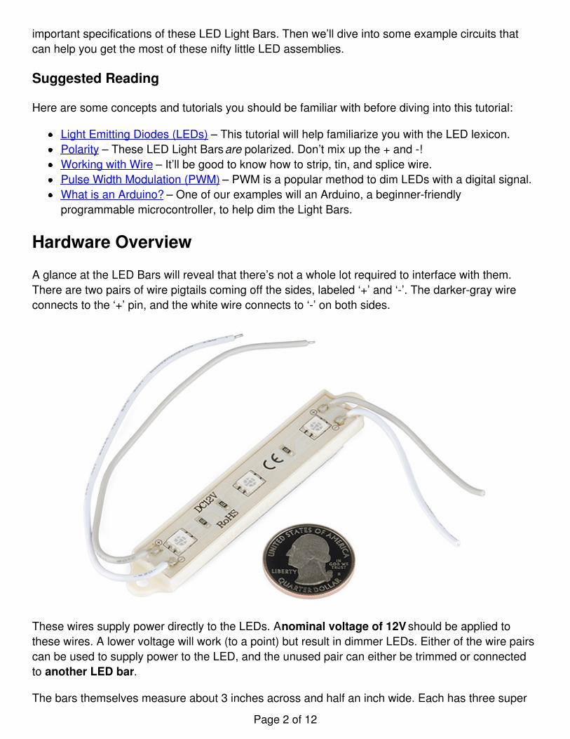
A glance at the LED Bars will reveal that there’s not a whole lot required to interface with them.There are two pairs of wire pigtails coming off the sides, labeled ‘+’ and ‘-’. The darker-gray wireconnects to the ‘+’ pin, and the white wire connects to ‘-’ on both sides.
These wires supply power directly to the LEDs. A nominal voltage of 12V should be applied tothese wires. A lower voltage will work (to a point) but result in dimmer LEDs. Either of the wire pairscan be used to supply power to the LED, and the unused pair can either be trimmed or connectedto another LED bar.
The bars themselves measure about 3 inches across and half an inch wide. Each has three super
Page 2 of 12

bright SMD LEDs, which are spaced by about 1.07".
For mounting purposes there are drill holes on either side of the board, and a peel-away sticky foamon the backside.
LED Characteristics
The “nominal” voltage for these LED Bars is 12V. “Nominal” as in that’s what’s recommended bythe manufacturer. They will work at lower voltages, although that’ll mean sacrificing somebrightness.
The table below shows some of the characteristics for each of the LED bar colors. These arevalues we found while testing the bars out. The minimum voltage was the lowest voltage where theLEDs were at recognizably lit up, although very dim. We recommend that you at least give theLEDs around 7V. The higher the voltage, the brighter your LED will be.
Color Minimum voltage Current @ 7V Current @ 9V Current @12V
White 4.84 V 8.35 mA 25.8 mA 55.2 mA
Red 2.8 V 13 mA 29.8 mA 54.0 mA
As far as current pull goes, both LED colors consume about the same when powered from between9 and 12V, up to about 55mA when powered at the nominal voltage.
Reverse Engineering the Light Bar Circuit
Looking at the visible components on the bars, it’s apparent that there’s not a lot to them. Three six-pin, SMD LEDs, and an equal number of resistors. We can easily reverse-engineer this circuit tofind out exactly how these things work.
Each SMD LED is actually a collection of three equal LEDs. The LED bar’s PCB is set up to stringthose LEDs in series, with the resistor in-line to limit current. The values of the resistors depend onthe color of the Bar. The red bar, for example uses 330Ω and the white bar uses 150Ω resistors.
Page 3 of 12

Connect three of those circuits in parallel an you have your LED bar!
Assembly Tips
In most cases, Light Bar assembly begins with stripping some wire. The wire pigtails on the barsare 20 AWG, and should be easy enough to strip with any, old wire stripper.
The wire lengths can be extended, if need be, with a little splice. Don’t forget to cover your splicewith heatshrink!
Alternatively the stripped pigtails can be tinned, crimped, or plugged directly into a matingconnector.
Stringing Bars
The ‘+’ and ‘-’ wires of one bar can be connected to another to string them together. More and morebars can be stringed until you start to approach the current limit of the 20 AWG wires – about 1.5A.With some back of the napkin calculations – 55mA per bar, 1.5A max – that’d be 25-ish bars.
Page 4 of 12

Mounting the Bars
There are two possible methods for mounting the LED bars. There are mounting holes on eitherend of the bar with a 0.15" drill diameter, allowing for the bars to be screwed down. Every bar alsoincludes a peel-away sticky-foam backing which adheres about as well as you could expect.
With a little prying, the PCB assembly part of the LED bar can be removed from the plasticmounting backing. This might be useful if your boards might need a tighter fit.
Page 5 of 12

Example Circuits
There are a variety of ways these LED bars can be controlled and illuminated. Let’s look at a fewexample circuits:
Direct Power
If you don’t care about dimming the LEDs, the easiest way to power them up is to connect themdirectly to a 12V power supply. Stick them in your enclosure or project, plug the supply in, andforget about them. If you’re looking for a supply that can source 12V, either a wall wart or a moregeneral power supply should be able to do the job.
Page 6 of 12

The DC Barrel Jack Screw Terminal Adapter makes connecting the 12V wall wart to the LED barway easy.
To gain a little control over the LEDs, you can add a switch in-line between the power source andeither the ‘+’ or ‘-’ wire of the first LED bar. Just make sure you pick a switch that can handle thehigh amounts of current that may run through it.
Dimming with MOSFETs
If you want to add some dimming control over your LED bar, MOSFETs combined with pulse widthmodulation are the tools you’ll need. There are a few approaches you can take to generating aPWM signal to control the MOSFET and LED bar. Here are a couple options:
Using an Arduino
If you’ve got an Arduino lying around (and what budding electrical engineer doesn’t these days?),that may prove to be the easiest way to control the LED bars via PWM. Use a circuit like below,with an n-channel MOSFET and the Arduino powered through the barrel jack connector by a 12Vwall wart:
Page 7 of 12

Make sure the positive LED wire (the gray one) is connected to ‘VIN’ of the Arduino, which shouldbe 12V (but could be 9V too). Our MOSFET Power Control Kit works perfectly for a circuit like this:
Page 8 of 12

Where the pin connected to the MOSFET gate could be any PWM-capable Arduino pin (3, 5, 6, 9,10, or 11 on most ‘duinos). Then just write a simple sketch which analogWrite()’s that pin to thedesired level. For example, you could slowly dim the LED bars with a sketch like this:
language:c/* MOSFET LED Bar Dimmer Example Arduino Sketch*/
// Define the pin connected to our MOSFET gate:int ledControlPin = 3; // Must be a PWM pin -- 3, 5, 6, 9, 10, 11
void setup(){ // Setup the LED control pin as output, start low pinMode(ledControlPin, OUTPUT); digitalWrite(ledControlPin, LOW);}
void loop(){ for (int i=0; i<=255; i+=5) // Sweep LED on { analogWrite(ledControlPin, i); delay(25); } delay(1000); // Hold at full brightness for (int i=255; i>=0; i-=5) // Sweep LED off { analogWrite(ledControlPin, i);
Page 9 of 12

delay(25); } delay(1000); // Hold at off}
Or come up with other nifty sketches. How about attaching a potentiometer, and controlling theLED’s intensity with that?
Using a 555 Timer
If you don’t have an Arduion around, or are looking for a more analog/elegant/cheap solution, youcould use a 555 timer and a handful of common components to generate the PWM signal. Here’san example circuit:
Most 555 timers can work at up to 16V, so you can run it directly off the 12V supply. Then twist thepotentiometer to adjust the brightness. Woo 555 timers!
Page 10 of 12

Resources and Going Further
Now that you know how easy it is to wire these LED bars up, what project are you going to makewith them? Need some inspiration, check out some of these tutorials:
GPS Wall Clock – This is our old tried and true example project using LED bars. Their ultra-brightness makes for some snazzy giant 7-segment displays.
Page 11 of 12

Or (on a slightly smaller scale) here are some other tutorials that might catch your interest:
The Soft Circuits: LED Feelings Pizza and Firefly Jar tutorials show how you can addillumination to clothing and other fabrics. These are great examples of e-textiles projects.PicoBuck Hookup Guide – The PicoBuck is a very powerful LED driver, capable of controllingLEDs even brighter than the LED bars.Light – If you want to know more about the physics behind light, and how it can bemanipulated, give this tutorial a read.
learn.sparkfun.com | CC BY-SA 3.0 | SparkFun Electronics | Niwot, Colorado
Page 12 of 12