lecture two OFDM - Arab Academy for Science, Technology...
39
E E CE5984 CE5984 Orthogonal Frequency Division Multiplexing and Related Orthogonal Frequency Division Multiplexing and Related Technologies Technologies Fall 2007 Fall 2007 Mohamed Essam Khedr OFDM Basics I
Transcript of lecture two OFDM - Arab Academy for Science, Technology...

EECE5984CE5984Orthogonal Frequency Division Multiplexing and Related Orthogonal Frequency Division Multiplexing and Related
TechnologiesTechnologiesFall 2007Fall 2007
Mohamed Essam Khedr
OFDM Basics I
TextbookTextbook• OFDM and MC-CDMA for broadband multi-user
communications by Lajos Hanzo et al
• Additional Readings:
• Richard van Nee and Ramjee Prasad, OFDM for Wireless Multimedia Communications, Artech House: 2000 (ISBN: OR90065306)
• Orthogonal Frequency Division Multiplexing for Wireless Communications by Ye (Geoffrey) Li (Editor), Gordon L. Stuber (Editor), ISBN 0387290958
• Ahmad Bahai and Burton Saltzberg, Multi-Carrier Digital Communications: Theory and Applications of OFDM, Plenum Publishing Corporation: 1999, ISBN: 0306462966.

SyllabusSyllabus• Wireless channels characteristics (7.5%) 1
– wireless channel modeling and characteristics• Large scale and small scale models• Common channel models• Channel categories and parameter calculation.• Prob. of error calculations
• OFDM Basics (10%) 1– History of OFDM– OFDM System model – Discrete-time signals & systems and DFT – Generation of subcarriers using the IFFT – Guard time, cyclic extension – Windowing – Choice of OFDM parameters & OFDM signal processing – Implementation complexity of OFDM versus single carrier modulation
• Modulation and Coding (10%) 2– Linear and nonlinear modulation – Interleaving and channel coding – Optimal bit and power allocation – Adaptive modulation

SyllabusSyllabus
• Analysis of OFDM systems (15%) 2– RF subsystems, amplifier classification and distortion– Crest factor (PAPR) reduction techniques
• Pre-distortion & adaptive pre-distortion techniques • clipping • coding techniques • partial transmit sequences (PTS) & modified PTS v. selective mapping • nonlinear quantization (companding)
– Phase noise and I&Q imbalance for QAM – Performance of OFDM in Gaussian channels– Performance of OFDM in Wide-band channels
• Synchronization and Estimation (15%) 2– ICI and OISI problems– Timing estimation – Frequency synchronization – Frequency error estimation algorithms – Carrier phase tracking – Frequency domain and time domain approaches for channel estimation
• coherent detection • differential detection

SyllabusSyllabus
• Multi-user OFDM Techniques (10%) 2– Adaptive modulations in OFDM– Power and bit allocations in OFDM– Scalable OFDM– Flash OFDM
• Diversity (7.5%) 1– Limits of capacity in fading environments – Channel models for multiple-input-multiple-output (MIMO) system – Receiver diversity techniques – Transmit diversity techniques and design criteria for fading channels – Block, trellis and layered space-time codes
• Multi-carrier CDMA (10%) 1– MC-CDMA versus DS-CDMA – MC-CDMA versus orthogonal frequency division multiple access (OFDMA)– OFDMA and MC-CDMA performance evaluation in wide-band channels

SyllabusSyllabus
• Physical and Medium Access Control (MAC) for IEEE 802.11 Networks (7.5%) 1
– Physical modeling of 802.11 networks– MAC system architecture – Frame exchange with RTS/CTS – Power management – Synchronization
• Physical and Medium Access Control (MAC) for IEEE 802.16 Networks (7.5%) 1
– Physical modeling of 802.16 networks– MAC system architecture – QoS guarantees in Wimax– Power management – Synchronization

GradingGrading
Type of assignment Percent of Grade Home works 20% Matlab Assignments 20% Midterm 20% Final project presentation and term paper 20% Final Exam 20%

MatlabMatlab Assignment 1Assignment 1
• Develop a WGN channel that accepts symbol input, adds noise to it with certain SNR and produces the noisy ouput.
• Develop a Flat Fading Channel following Rayleigh and ricean distribution
• Develop a Frequency selective channel following Rayleighand ricean distribution – All inputs to the channel are baseband signals.– Compare with the matlab functions (if exist)– Plot the probability of error vs SNR

Lecture one Fading channelsLecture one Fading channels

Impulse Impulse RResponseesponse CCharacterizationharacterization
τ(t0)t0
t2τ(t2)
t1τ(t1)
Time spreading property
Time va
riatio
ns property
Impulse response: Time-spreading : multipath
and time-variations: time-varying environment

������������ ������
CA
D
BReceiverTransmitter
A: free spaceB: reflectionC: diffractionD: scattering
��������� �������� ����������� ������ �������
����� ���� ���� �������� ������������������
� �������� ���� ������������������ ����������

Multipath Propagation Multipath Propagation –– Simple ModelSimple Model
• hc(t) = ����k ααααk δδδδ(t - ττττk)where k = 0, …, K-1
αk : path gain (complex)τ0 = 0 normalize relative
delay of first path∆k = τk - τ0 difference in
time-of-flight
| α| α| α| α0 |||| | α| α| α| α1 |||| | α| α| α| α2 ||||
∆∆∆∆1 ∆∆∆∆2
αααα0
αααα1
αααα2
path delaypath delaypath attenuationpath attenuation path phasepath phase
( ) ( ) ( ) ( )1
0
, i
Lj t
i ii
h t a t e φτ δ τ τ−
=
= −�

Impact of Impact of MultipathMultipath: Delay Spread & ISI: Delay Spread & ISI
-6 -4 -2 0 2 4 6-0.2
0
0.2
0.4
0.6
0.8
1
t/Ts
2Ts 4Ts
Ts
-6 -4 -2 0 2 4 6 8-0.5
0
0.5
1
t/Ts
-6 -4 -2 0 2 4 6 8
-0.2
0
0.2
0.4
0.6
0.8
t/Ts
Max delay spread = effective number of symbol periods occupied by channel
Requires equalization to remove resulting ISI

��� ����� ������ �! �������������
"�#��������$������� Tm
"�#��������$��������$������������������$�%
&�����������'��� ("�����$�����������������������
( )( )
( )( )
22
h h
h h
d d
d dτ
τ φ τ τ τ φ τ τσ
φ τ τ φ τ τ
� �� �= −� �� �
� �� �
( )hφ τ
τTm

��� ����� ������ �! �������������
������ ����������� �����
1m mB T≈
( )H fφ ∆
Bm
f0)���� ������ ����� ����������
)����������������*�� ���!������ ���� ����������
���Bm '������������������ ��� �������%
)�������*�� $������������� ����������Bm '�����
������������� ��� ��������%

��� ����� ������ �! �������������
"�#������������������
+������������ ���������� ,���������-��������������������!%+��������������������������������������� ν
Bd
0
Bd
( )HS ν
cos cosd
Vfν α α
λ= =

����$, ��������������� ����
������� ����� ν
����$ τ
0
L ./0 ������� �����$,������� �����
L ./0 ������� �����$,������� �����
Bd
( ) ( ) ( ) ( )1
2
0
, i i
Lj t
i ii
h t a t e πν φτ δ τ τ−
+
=
= −�

Statistical ModelsStatistical Models• Design and performance analysis based on statistical ensemble of
channels rather than specific physical channel.
• Rayleigh flat fading model: many small scattered paths
Complex circular symmetric Gaussian .
• Rician model: 1 line-of-sight plus scattered paths

&�����������������(�$�����!
( ) 2 222
aap a e σ
σ−= ( )
1
2p φ
π=
( ) ( ) ( ) ( ) ( ) ( ) ( )ij t j ti
i
c t a t e x t j y t a t eφ φ= = + =�
)���������� ����'��������,������!�)(���� ����������,������! �����# ���� ����� ����
������*��������� ������������ ���� ����� ������ ���������$��1�����������������'������
(�$����� �����������(�$����� ����������� ����� ����������� ����� �����������

&�����������������(� �!
) �������� �������� ��%�%'23�!��������� �������������� ����� �����#1������ ������'�� ������
&��������������������������!����� ��������
(� � �����������(� � �����������"��������������� ��� ������� -��������� 4���
"��������������� ��� ������� -��������� 4���
( ) ( ) ( ) ( ) ( )0 0
ij t j ti
i
c t a a t e a a t eφ φ= + = +�
( ) ( )22 20 2 0
02 2
a aa aap a e I
σ
σ σ− +
= � � �
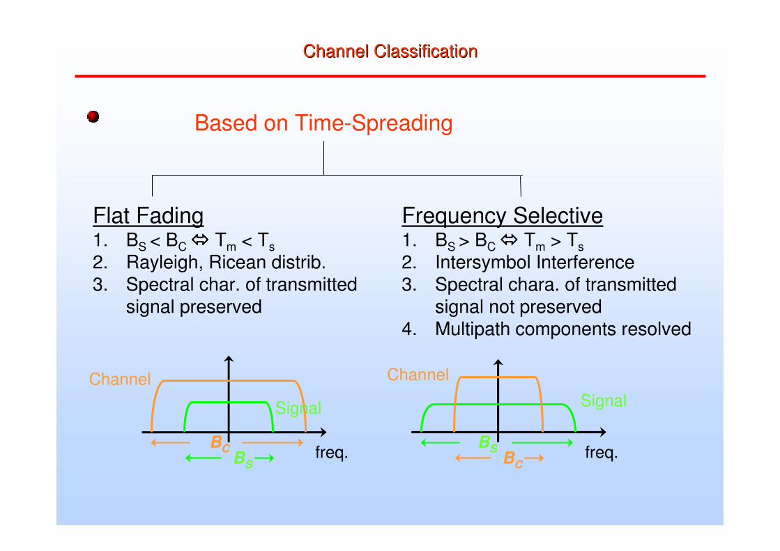
Channel ClassificationChannel Classification
Based on Time-Spreading
Flat Fading1. BS < BC ���� Tm < Ts2. Rayleigh, Ricean distrib.3. Spectral char. of transmitted
signal preserved
Frequency Selective1. BS > BC ���� Tm > Ts2. Intersymbol Interference3. Spectral chara. of transmitted
signal not preserved4. Multipath components resolved
Signal
Channel
freq.BS
BC freq.BC
BS
Channel
Signal

Channel ClassificationChannel Classification
Based on Time-Variations
Fast Fading1. High Doppler Spread2. 1/Bd ≅ TC < Ts
Slow Fading1. Low Doppler Spread2. 1/Bd ≅ TC> Ts
Signal
freq.BD
BSfreq.BS
BD
Doppler
Signal
Doppler

Multicarrier ModulationMulticarrier Modulation• Divide broadband channel into narrowband subchannels
– No ISI in subchannels if constant gain in every subchannel and if ideal sampling
• Orthogonal Frequency Division Multiplexing– Based on the fast Fourier transform– Standardized for DAB, DVB-T, IEEE 802.11a, 802.16a, HyperLAN II– Considered for fourth-generation mobile communication systems
subchannel
frequency
mag
nitu
de
carrier
channel
Subchannels are 312 kHz wide in 802.11a and HyperLAN II

An OFDM SymbolAn OFDM Symbol
N-pointInverse
FFT
X1X2
x0x2x3
xN-1XN-1
X0
N subsymbolsone symbolN complex
samples
N samplesv samples CP: Cyclic Prefix
CP CPs y m b o l i s y m b o l ( i+1)
copy copy
• Bandpass transmission allows for complex waveforms– Transmit: y(t) = Re{(I(t)+j Q(t)) exp(j2ππππ fc t)}
= I(t) cos(2ππππ fc t) – Q(t) sin(2 ππππ fc t)

Introduction to OFDMIntroduction to OFDM

P/SQAM
decoder
invert channel
=frequencydomain
equalizer
S/P
quadratureamplitude
modulation (QAM)
encoder
N-IFFTadd
cyclic prefix
P/SD/A +
transmit filter
N-FFT S/Premove cyclic prefix
TRANSMITTER
RECEIVER
N subchannels N complex samples
N complex samplesN subchannels
Receive filter
+A/D
multipath channel
An OFDM Modem An OFDM Modem
Bits
00110
Coded OFDM (COFDM)Coded OFDM (COFDM)
• Error correction is necessary in OFDM systems• Forward error correction (FEC)
– Adds redundancy to data stream– Examples: convolutional codes, block codes– Mitigates the effects of bad channels– Reduces overall throughput according to the coding rate k/n
• Automatic repeat request (ARQ)– Adds error detecting ability to data stream– Examples: 16-bit cyclic redundancy code– Used to detect errors in an OFDM symbol– Bad packets are retransmitted (hopefully the channel changes)– Usually used with FEC– Minus: Ineffective in broadcast systems

Typical Coded OFDM EncoderTypical Coded OFDM Encoder
FEC
Bitwise Interleaving
SymbolMapping
• Reed-Solomon and/or convolutional code
• Intersperse coded and uncoded bits
Data bits Parity bits
Rate 1/2
• Map bits to symbols

Typical Coded OFDM DecoderTypical Coded OFDM Decoder
Frequency-domainequalization
SymbolDemapping
Deinterleaving
Decoding
• Symbol demapping– Produce soft estimate of each bit– Improves decoding

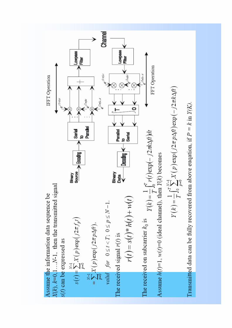
OFDM Mathematics1
2
0
( ) k
Nj f t
kk
s t X e π−
=
= � t ≡ [ 0,Τos]
Orthogonality Condition
*1 2
0
( ). ( ) 0T
g t g t dt =�In our case
2 2
0
. 0p q
Tj f t j f te e dtπ π− =�
For p ≠ q Where fk=k/T
os
os
os

Transmitted Spectrum

resemblesIDFT!
Spectrum of the modulated data symbolsSpectrum of the modulated data symbols
• Rectangular Window of duration T0
• Has a sinc-spectrum with zeros at 1/ T0
• Other carriers are put in these zeros
• ���� sub-carriers are orthogonal
Frequency
Magnitude
�−
=
−∆−=1
0
)(2,, )()(
N
i
kTtfijkikBB exkTtwts π
N sub-carriers:
T0
Subcarrier orthogonality must be preservedCompromised by timing jitter, frequency offset, and fading.

OFDM terminology
• Orthogonal carriers referred to as subcarriers {fi,i=0,....N-1}.
• OFDM symbol period {Tos=N x Ts}.
• Subcarrier spacing ∆f = 1/Tos.

OFDM and FFT
• Samples of the multicarrier signal can be obtained using the IFFT of the data symbols - a key issue.
• FFT can be used at the receiver to obtain the data symbols.
• No need for ‘N’ oscillators,filters etc.
• Popularity of OFDM is due to the use of IFFT/FFT which have efficient implementations.

OFDM Signal1
,0
( ) ( ( ))N
n k k osn k
s t X g t nT∞ −
=−∞ =
= −� �2
( )0
kj f t
k
eg t
π�= �
�
t ≡ [ 0,Τos]
Otherwise
ko s
kf
T= K=0,..........N-1
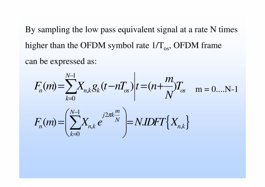
By sampling the low pass equivalent signal at a rate N times
higher than the OFDM symbol rate 1/Tos, OFDM frame
can be expressed as:
1
,0
( ) ( ) ( )N
n n k k os osk
mF m X g t nT t n T
N
−
=
= − = +�
{ }1 2
, ,0
( ) .mN j kN
n n k n kk
F m X e N IDFT Xπ−
=
= =�� ��
m = 0....N-1
Interpretation of IFFT&FFTInterpretation of IFFT&FFT
• IFFT at the transmitter & FFT at the receiver
• Data symbols modulate the spectrum and the time domain symbols are obtained using the IFFT.
• Time domain symbols are then sent on the channel.
• FFT at the receiver to obtain the data.