Lecture Notes Set 5 -Measurement Systems - 2008-09€¦ · · 2014-07-21Measurement Systems Dr...
25
Page 4.1 MFE3004 Mechatronics I C. Pace MFE 3004 Mechatronics I Measurement Systems Dr Conrad Pace Page 4.2 MFE3004 Mechatronics I C. Pace Introduction to Measurement Systems • Role of Measurement Systems – Detection – receive an external stimulus (ex. Displacement) – Selection – measurement of one property of that stimulus (ex. direction of displacement, filtering our disturbances) – Signal Management – transform signal that represents the measured property in a form legible by the information processor (ex. amplification, linearisation, digital conversion) – Communication – communicate signal to the observer/ information processor
Transcript of Lecture Notes Set 5 -Measurement Systems - 2008-09€¦ · · 2014-07-21Measurement Systems Dr...
1
Page 4.1MFE3004 Mechatronics IC. Pace
MFE 3004Mechatronics I
Measurement SystemsDr Conrad Pace
Page 4.2MFE3004 Mechatronics IC. Pace
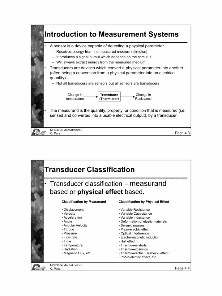
Introduction to Measurement Systems• Role of Measurement Systems
– Detection – receive an external stimulus (ex. Displacement)
– Selection – measurement of one property of that stimulus (ex. direction of displacement, filtering our disturbances)
– Signal Management – transform signal that represents the measured property in a form legible by the information processor (ex. amplification, linearisation, digital conversion)
– Communication – communicate signal to the observer/ information processor
2
Page 4.3MFE3004 Mechatronics IC. Pace
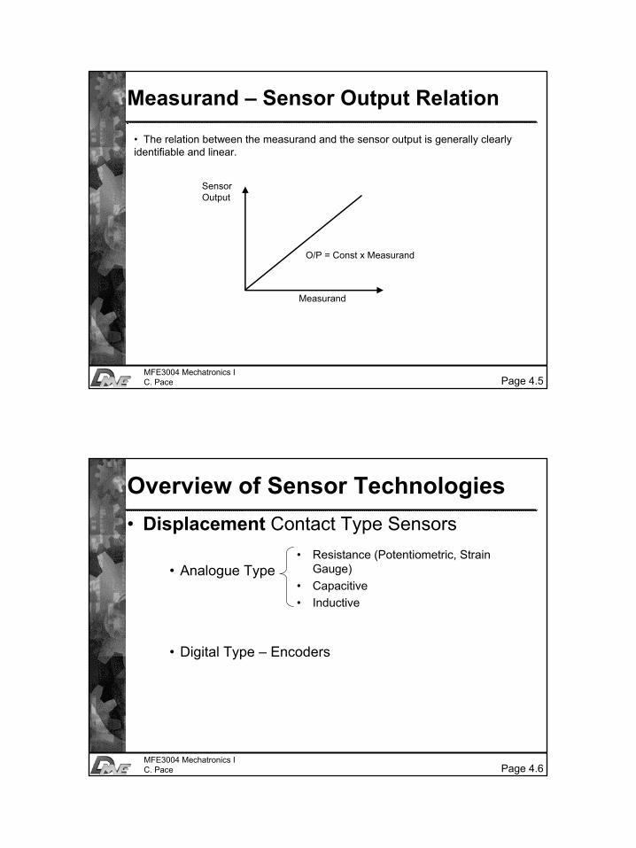
Introduction to Measurement Systems• A sensor is a device capable of detecting a physical parameter
– Receives energy from the measured medium (stimulus)– It produces a signal output which depends on the stimulus– Will always extract energy from the measured medium
• Transducers are devices which convert a physical parameter into another (often being a conversion from a physical parameter into an electrical quantity).– Not all transducers are sensors but all sensors are transducers
• The measurand is the quantity, property, or condition that is measured (i.e. sensed and converted into a usable electrical output), by a transducer
Transducer(Thermistor)
Change intemperature
Change inResistance
Page 4.4MFE3004 Mechatronics IC. Pace
Transducer Classification
• Transducer classification – measurandbased or physical effect based.
Classification by Measurand
• Displacement• Velocity• Acceleration• Angle• Angular Velocity• Torque• Pressure• Flow rate• Time• Temperature• Radiation• Magnetic Flux, etc..
Classification by Physical Effect
• Variable Resistance• Variable Capacitance• Variable Inductance• Deformation of elastic materials• Seismic masses• Piezo-electric effect• Optical interference• Electro-magnetic induction• Hall effect• Thermo-resistivity• Thermo-expansion• Thermo-electric (Seebeck) effect• Photo-electric effect, etc..
3
Page 4.5MFE3004 Mechatronics IC. Pace
Measurand – Sensor Output Relation
• The relation between the measurand and the sensor output is generally clearly identifiable and linear.
SensorOutput
Measurand
O/P = Const x Measurand
Page 4.6MFE3004 Mechatronics IC. Pace
Overview of Sensor Technologies• Displacement Contact Type Sensors
• Analogue Type
• Digital Type – Encoders
• Resistance (Potentiometric, Strain Gauge)
• Capacitive• Inductive
4
Page 4.7MFE3004 Mechatronics IC. Pace
Overview of Sensor Technologies• Displacement – Contact Type Sensors
(k)
(1-k)RVref
RL
Vout
Cantilever beam
Strain α deflection(for measuring smalldistances
Potentiometer Application
Strain Gauge Application
Page 4.8MFE3004 Mechatronics IC. Pace
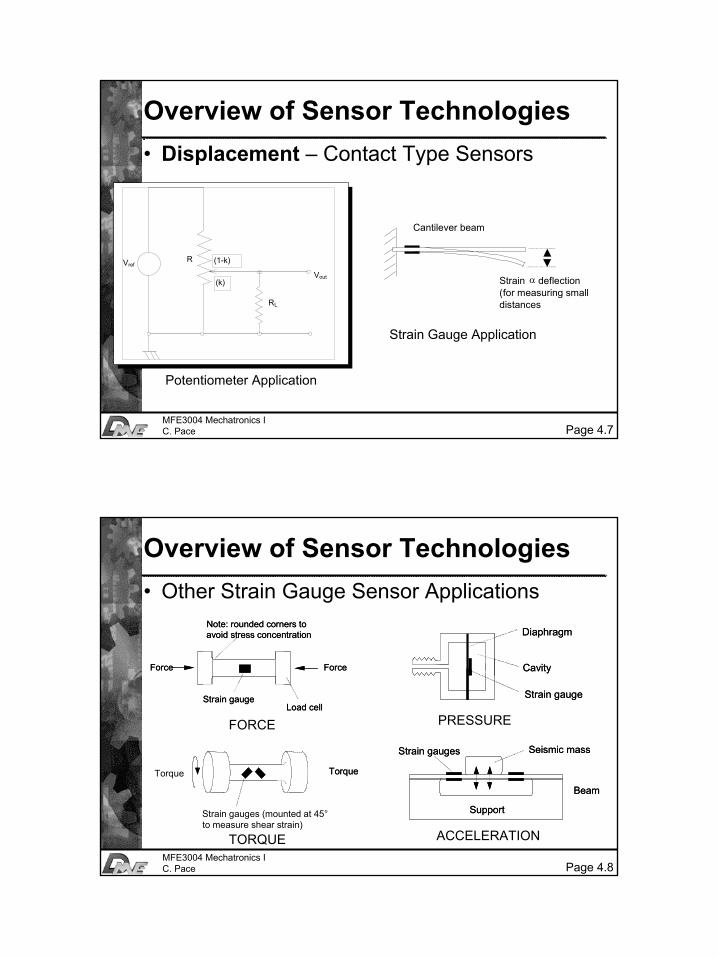
Overview of Sensor Technologies• Other Strain Gauge Sensor Applications
Force Force
Strain gaugeLoad cell
Note: rounded corners toavoid stress concentration
Force Force
Strain gaugeLoad cell
Note: rounded corners toavoid stress concentration
Torque Torque
Strain gauges (mounted at 45°to measure shear strain)
Torque Torque
Strain gauges (mounted at 45°to measure shear strain)
Diaphragm
Cavity
Strain gauge
Diaphragm
Cavity
Strain gauge
Seismic massStrain gauges
Beam
Support
Seismic massStrain gauges
Beam
Support
FORCE
TORQUE
PRESSURE
ACCELERATION
5
Page 4.9MFE3004 Mechatronics IC. Pace
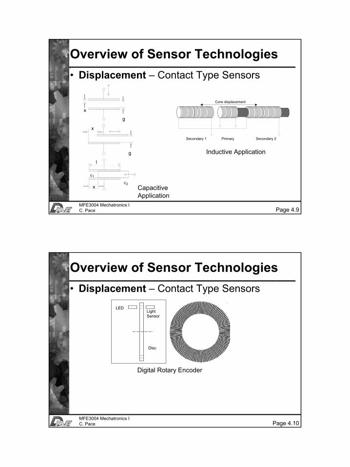
Overview of Sensor Technologies• Displacement – Contact Type Sensors
Capacitive Application
x
g
x
g
x
l
ε1
ε2
Core displacement
Secondary 1 Primary Secondary 2
Inductive Application
Page 4.10MFE3004 Mechatronics IC. Pace
Overview of Sensor Technologies• Displacement – Contact Type Sensors
LEDLightSensor
Disc
Digital Rotary Encoder
6
Page 4.11MFE3004 Mechatronics IC. Pace
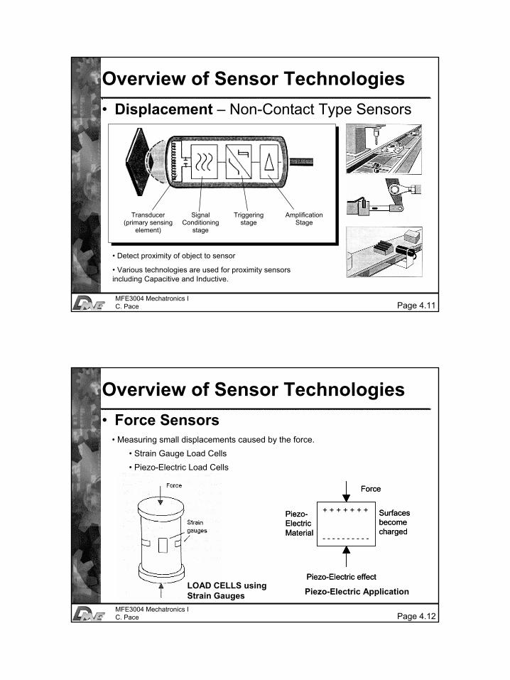
Overview of Sensor Technologies• Displacement – Non-Contact Type Sensors
• Detect proximity of object to sensor
• Various technologies are used for proximity sensors including Capacitive and Inductive.
Transducer(primary sensing
element)
SignalConditioning
stage
Triggeringstage
AmplificationStage
Page 4.12MFE3004 Mechatronics IC. Pace
Overview of Sensor Technologies• Force Sensors
• Measuring small displacements caused by the force.• Strain Gauge Load Cells• Piezo-Electric Load Cells
LOAD CELLS using Strain Gauges Piezo-Electric Application
+ + + + + + +
- - - - - - - - - -
Force
Surfacesbecomecharged
Piezo-Electric effect
Piezo-ElectricMaterial
+ + + + + + +
- - - - - - - - - -
Force
Surfacesbecomecharged
Piezo-Electric effect
Piezo-ElectricMaterial
7
Page 4.13MFE3004 Mechatronics IC. Pace
Overview of Sensor Technologies• Temperature Sensors
– Use of expansion/ contraction of solids or liquids– Measurement of gas pressures– Change in electrical resistance– Thermoelectric e.m.f.– Radiation measurement
Page 4.14MFE3004 Mechatronics IC. Pace
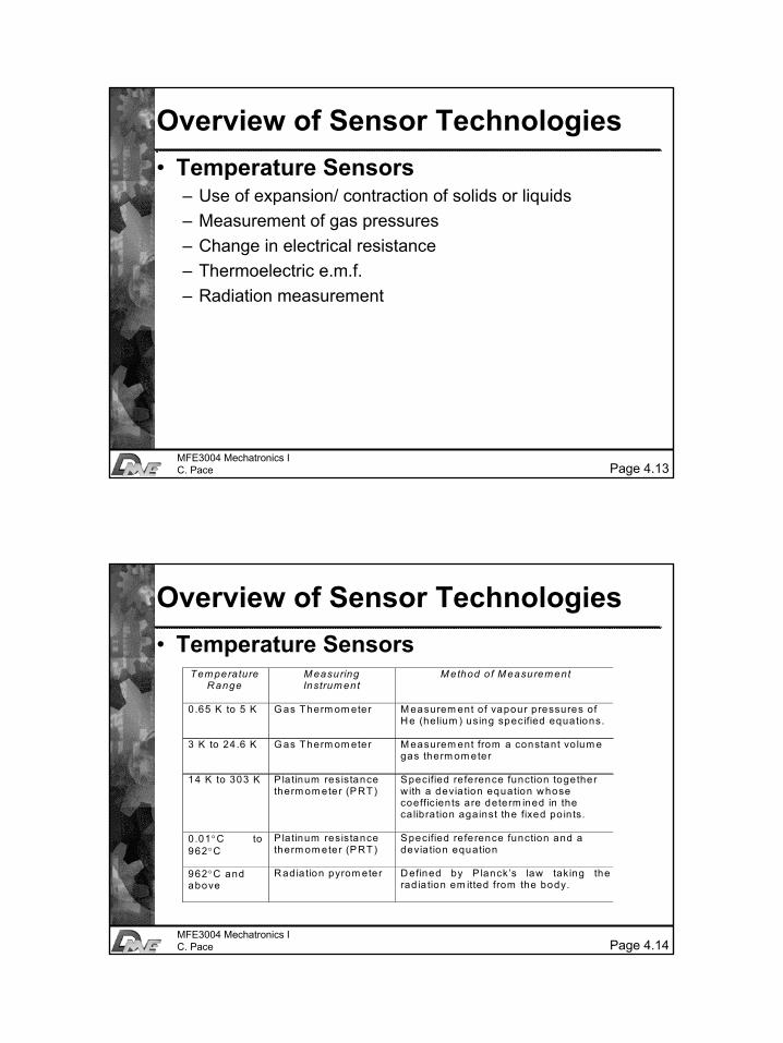
Overview of Sensor Technologies• Temperature Sensors
Tem peratureR ange
M easuringInstrum ent
M ethod o f M easurem ent
0.65 K to 5 K G as Therm om eter M easurem ent of vapour pressures ofH e (he lium ) using specified equations.
3 K to 24.6 K G as Therm om eter M easurem ent from a constant vo lum egas therm om eter
14 K to 303 K P la tinum resistancetherm om eter (PRT)
Specified reference function togetherw ith a devia tion equation whosecoeffic ien ts are determ ined in theca libration against the fixed po in ts.
0 .01°C to962°C
Platinum resistancetherm om eter (PRT)
Specified reference function and adevia tion equation
962°C andabove
R adia tion pyrom eter D efined by P lanck’s law taking therad ia tion em itted from the body.
8
Page 4.15MFE3004 Mechatronics IC. Pace
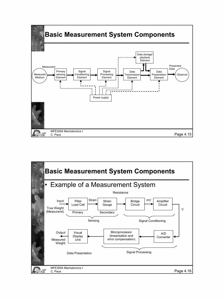
Basic Measurement System Components
Primary sensing Element
Power supply
Measurand
Measured Medium
Signal Conditioning
Element
Signal Processing
Element
Data Transmission
Element
Data Presentation
Element Observer
Data storage/ playback Element
Presented Data
Page 4.16MFE3004 Mechatronics IC. Pace
Basic Measurement System Components
• Example of a Measurement System
Pillar Load Cell
Strain Gauge
Bridge Circuit
Amplifier Circuit
Visual Display
Unit
Microprocessor (linearisation and
error compensation)
A/D Converter
Signal Processing
mV
Resistance
V
Strain Input
True Weight (Measurand) Primary Secondary
Sensing Signal Conditioning
Output
Measured Weight
Data Presentation
9
Page 4.17MFE3004 Mechatronics IC. Pace
Application Areas of Measurement Systems
• Monitoring of Processes and Operations • Control of Processes and Operations
– Most common application in mechatronic products and processes.
• Experimental Engineering Analysis– In solving engineering problems, two general methods are
available: theoretical and experimental. – Measurement systems are a fundamental component of
experimental work.
Page 4.18MFE3004 Mechatronics IC. Pace
Sensory Characteristics
• Measurand Characteristics• Electrical Characteristics• Mechanical Characteristics• Performance Characteristics
10
Page 4.19MFE3004 Mechatronics IC. Pace
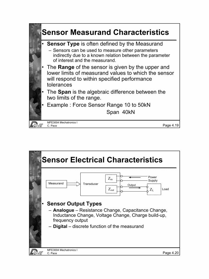
Sensor Measurand Characteristics• Sensor Type is often defined by the Measurand
– Sensors can be used to measure other parameters indirectly due to a known relation between the parameter of interest and the measurand.
• The Range of the sensor is given by the upper and lower limits of measurand values to which the sensor will respond to within specified performance tolerances
• The Span is the algebraic difference between the two limits of the range.
• Example : Force Sensor Range 10 to 50kNSpan 40kN
Page 4.20MFE3004 Mechatronics IC. Pace
Sensor Electrical Characteristics
• Sensor Output Types– Analogue – Resistance Change, Capacitance Change,
Inductance Change, Voltage Change, Charge build-up, frequency output
– Digital – discrete function of the measurand
Transducer
Zin
Zout
Power Supply
Output
ZL Load
Measurand
11
Page 4.21MFE3004 Mechatronics IC. Pace
Sensor Mechanical Characteristics• Mechanical Characteristics define the Physical
interface of the sensor– Mode of mounting– Sensor Orientation– Environmental Conditions to which the sensor is
exposed (ex. vibration and mechanical stress)
Page 4.22MFE3004 Mechatronics IC. Pace
Sensor Performance Characteristics
• Classification of Performance Characteristics– Static– Dynamic– Environmental
12
Page 4.23MFE3004 Mechatronics IC. Pace
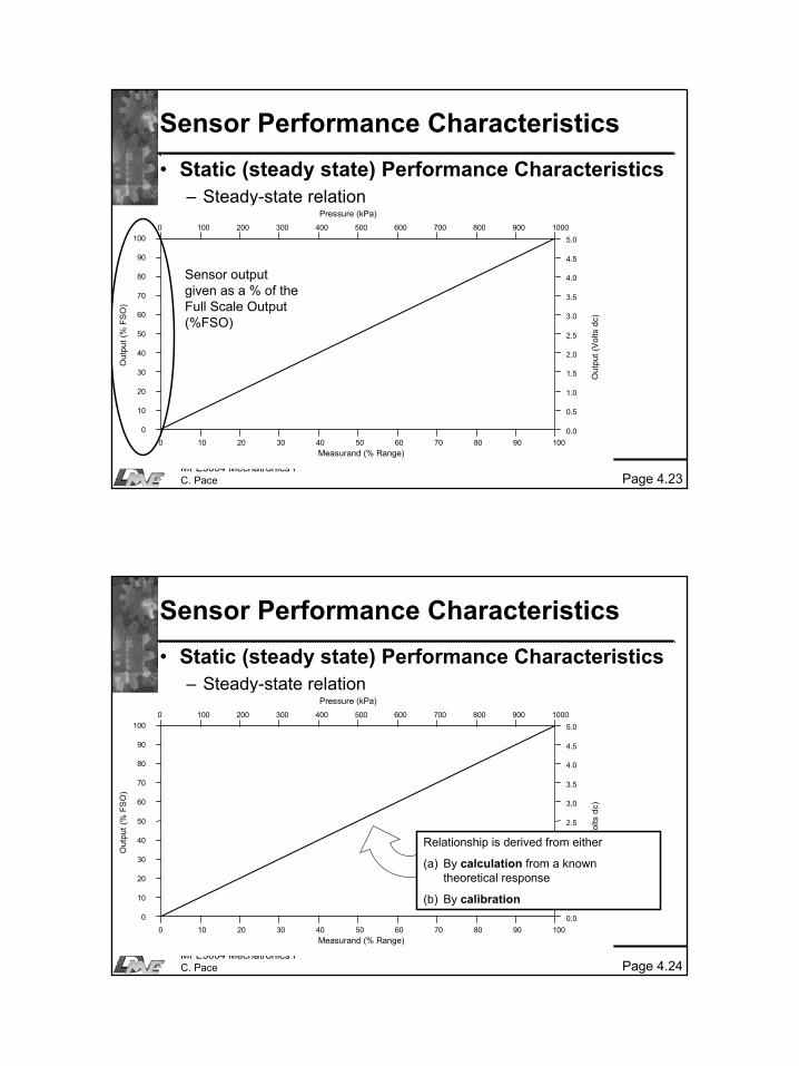
Sensor Performance Characteristics• Static (steady state) Performance Characteristics
– Steady-state relation
0 10 20 30 40 50 60 70 80 90 100
0 100 200 300 400 500 600 700 800 900 1000100
90
80
70
60
50
40
30
20
10
0
5.0
4.5
4.0
3.5
3.0
2.5
2.0
1.5
1.0
0.5
0.0
Out
put (
% F
SO
)
Out
put (
Vol
ts d
c)
Pressure (kPa)
Measurand (% Range)
Sensor output given as a % of the Full Scale Output (%FSO)
Page 4.24MFE3004 Mechatronics IC. Pace
Sensor Performance Characteristics• Static (steady state) Performance Characteristics
– Steady-state relation
0 10 20 30 40 50 60 70 80 90 100
0 100 200 300 400 500 600 700 800 900 1000100
90
80
70
60
50
40
30
20
10
0
5.0
4.5
4.0
3.5
3.0
2.5
2.0
1.5
1.0
0.5
0.0
Out
put (
% F
SO
)
Out
put (
Vol
ts d
c)
Pressure (kPa)
Measurand (% Range)
Relationship is derived from either
(a) By calculation from a known theoretical response
(b) By calibration
13
Page 4.25MFE3004 Mechatronics IC. Pace
Sensor Performance Characteristics
0 10 20 30 40 50 60 70 80 90 100
0 100 200 300 400 500 600 700 800 900 1000100
90
80
70
60
50
40
30
20
10
0
5.0
4.5
4.0
3.5
3.0
2.5
2.0
1.5
1.0
0.5
0.0
Out
put (
% F
SO
)
Out
put (
Vol
ts d
c)
Pressure (kPa)
Measurand (% Range)
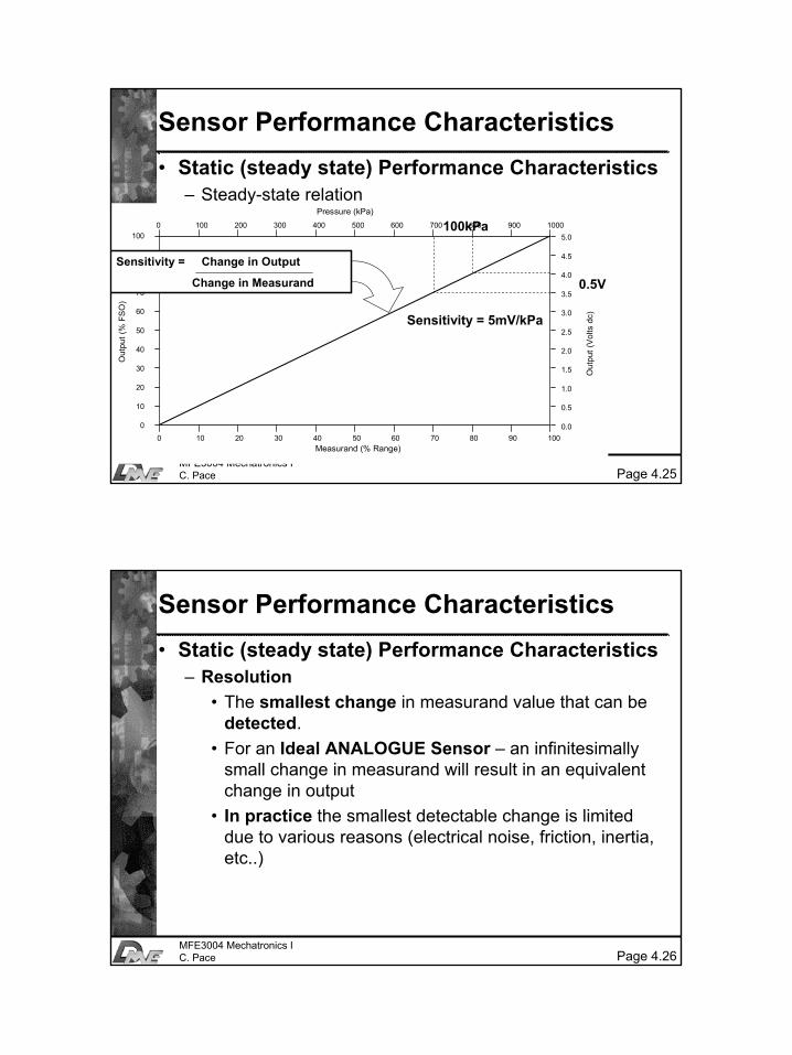
• Static (steady state) Performance Characteristics– Steady-state relation
Sensitivity = Change in Output
Change in Measurand 0.5V
100kPa
Sensitivity = 5mV/kPa
Page 4.26MFE3004 Mechatronics IC. Pace
Sensor Performance Characteristics• Static (steady state) Performance Characteristics
– Resolution• The smallest change in measurand value that can be
detected. • For an Ideal ANALOGUE Sensor – an infinitesimally
small change in measurand will result in an equivalent change in output
• In practice the smallest detectable change is limited due to various reasons (electrical noise, friction, inertia, etc..)
14
Page 4.27MFE3004 Mechatronics IC. Pace
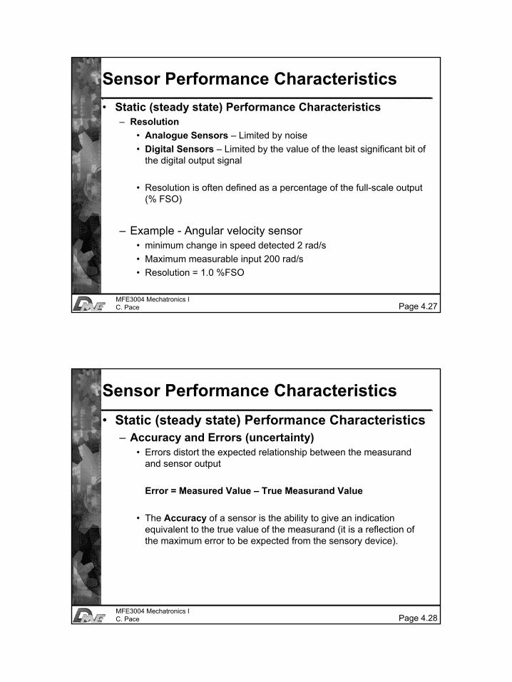
Sensor Performance Characteristics• Static (steady state) Performance Characteristics
– Resolution• Analogue Sensors – Limited by noise• Digital Sensors – Limited by the value of the least significant bit of
the digital output signal
• Resolution is often defined as a percentage of the full-scale output (% FSO)
– Example - Angular velocity sensor • minimum change in speed detected 2 rad/s• Maximum measurable input 200 rad/s• Resolution = 1.0 %FSO
Page 4.28MFE3004 Mechatronics IC. Pace
Sensor Performance Characteristics• Static (steady state) Performance Characteristics
– Accuracy and Errors (uncertainty)• Errors distort the expected relationship between the measurand
and sensor output
Error = Measured Value – True Measurand Value
• The Accuracy of a sensor is the ability to give an indication equivalent to the true value of the measurand (it is a reflection of the maximum error to be expected from the sensory device).

15
Page 4.29MFE3004 Mechatronics IC. Pace
Sensor Performance Characteristics• Static (steady state) Performance Characteristics
– Accuracy • Dependent on the Errors to which the sensor is subjected• Reflects the precision of calibration of the sensor• Is stipulated as a %FSO
– Example : Temperature Sensor• Range 0 to 200°C• Sensor Max. Error of ± 10°C• Sensor Accuracy = ± 5% FSO
Page 4.30MFE3004 Mechatronics IC. Pace
Sensor Performance Characteristics• Static (steady state) Performance Characteristics
– Error Types – REPEATABILITY• The ability of the sensor to give the same output for
repeated applications of the same input measurandvalue
Repeatability = Maximum – Minimum Values Given x 100%
FSO
16
Page 4.31MFE3004 Mechatronics IC. Pace
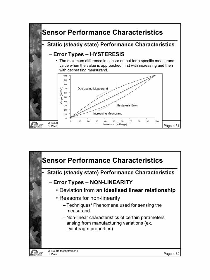
Sensor Performance Characteristics• Static (steady state) Performance Characteristics
– Error Types – HYSTERESIS• The maximum difference in sensor output for a specific measurand
value when the value is approached, first with increasing and then with decreasing measurand.
0 10 20 30 40 50 60 70 80 90 100
100
90
80
70
60
50
40
30
20
10
0
Out
put (
% F
SO
)
Measurand (% Range)
Decreasing Measurand
Increasing Measurand
Hysteresis Error
Page 4.32MFE3004 Mechatronics IC. Pace
Sensor Performance Characteristics• Static (steady state) Performance Characteristics
– Error Types – NON-LINEARITY• Deviation from an idealised linear relationship• Reasons for non-linearity
– Techniques/ Phenomena used for sensing the measurand
– Non-linear characteristics of certain parameters arising from manufacturing variations (ex. Diaphragm properties)
17
Page 4.33MFE3004 Mechatronics IC. Pace
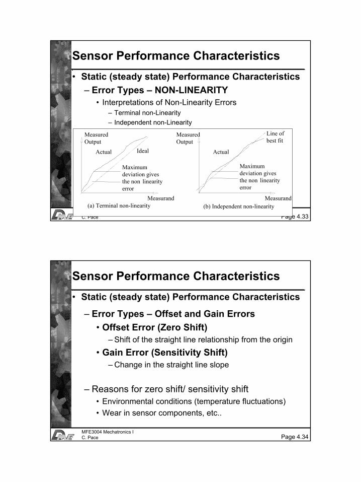
Sensor Performance Characteristics• Static (steady state) Performance Characteristics
– Error Types – NON-LINEARITY• Interpretations of Non-Linearity Errors
– Terminal non-Linearity– Independent non-Linearity
Maximum deviation gives the non linearity error
Ideal
Measurand
Measured Output
Actual
Maximum deviation gives the non linearity error
Line of best fit
Measurand
Measured Output
Actual
(a) Terminal non-linearity (b) Independent non-linearity
Page 4.34MFE3004 Mechatronics IC. Pace
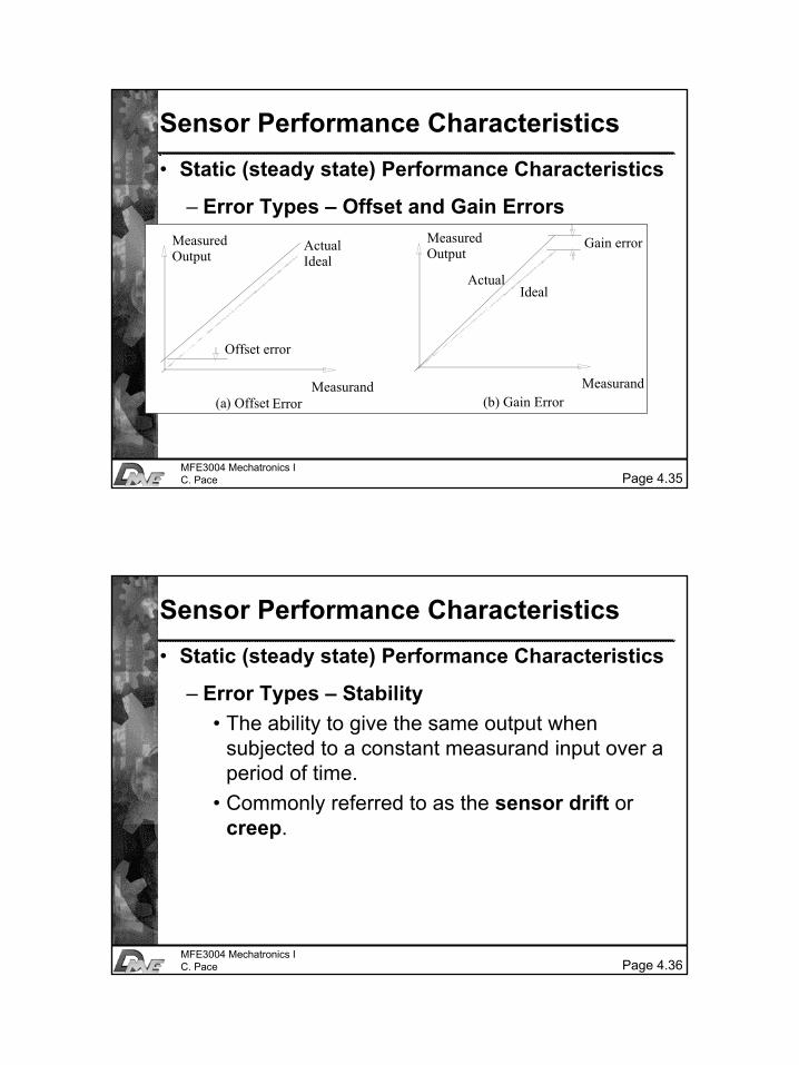
Sensor Performance Characteristics• Static (steady state) Performance Characteristics
– Error Types – Offset and Gain Errors• Offset Error (Zero Shift)
– Shift of the straight line relationship from the origin• Gain Error (Sensitivity Shift)
– Change in the straight line slope
– Reasons for zero shift/ sensitivity shift• Environmental conditions (temperature fluctuations)• Wear in sensor components, etc..
18
Page 4.35MFE3004 Mechatronics IC. Pace
Sensor Performance Characteristics• Static (steady state) Performance Characteristics
– Error Types – Offset and Gain Errors
(a) Offset ErrorMeasurand
(b) Gain Error
Offset error
ActualIdeal
Measurand
Measured Output
Gain error
Actual
Measured Output
Ideal
Page 4.36MFE3004 Mechatronics IC. Pace
Sensor Performance Characteristics• Static (steady state) Performance Characteristics
– Error Types – Stability• The ability to give the same output when
subjected to a constant measurand input over a period of time.
• Commonly referred to as the sensor drift or creep.
19
Page 4.37MFE3004 Mechatronics IC. Pace
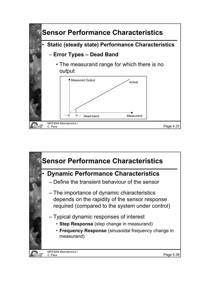
Sensor Performance Characteristics• Static (steady state) Performance Characteristics
– Error Types – Dead Band
• The measurand range for which there is no output
Dead-band
Measured Output
Measurand
Actual
Page 4.38MFE3004 Mechatronics IC. Pace
Sensor Performance Characteristics
• Dynamic Performance Characteristics– Define the transient behaviour of the sensor
– The importance of dynamic characteristics depends on the rapidity of the sensor response required (compared to the system under control)
– Typical dynamic responses of interest• Step Response (step change in measurand)• Frequency Response (sinusoidal frequency change in
measurand)

20
Page 4.39MFE3004 Mechatronics IC. Pace
Sensor Performance Characteristics
• Dynamic Performance Characteristics– Frequency Response
• Amplitude Ratio = Sensor Output Magnitude/ Measurand Magnitude
• Phase Shift = Phase lag between Sensor output and Measurand
Page 4.40MFE3004 Mechatronics IC. Pace
Sensor Performance Characteristics
• Dynamic Performance Characteristics– Frequency Response
Frequency range AFrequency range B
Response Curve A
Response Curve B

21
Page 4.41MFE3004 Mechatronics IC. Pace
Sensor Performance Characteristics
• Dynamic Performance Characteristics– Step Response
Time
Dead Time
0
100
90
80
70
60
50
40
30
20
10
0
Per
cent
of o
utpu
t cha
nge
Application of Measurand Change
Rise Time
63.2%
95%
5%
Time Constant
Response Time
Transient Response Steady-State Response
Page 4.42MFE3004 Mechatronics IC. Pace
Sensor Performance Characteristics
• Dynamic Performance Characteristics– Step Response
0
160
140
120
100
80
60
40
20
0
Per
cent
of o
utpu
t cha
nge
Application of Measurand Change
Maximum Overshoot
Steady state output value
22
Page 4.43MFE3004 Mechatronics IC. Pace
Sensor Performance Characteristics
• Environment Characteristics– Describe the environmental effects on the sensor
performance– Example
• Temperature Offset and Gain Errors (amongst the most common environmental effects on sensors)
– %FSO per °C change in temperature
• Temperature Offset Error is often given as a Temperature Sensitivity – change in output which is solely due to changes in temperature
Page 4.44MFE3004 Mechatronics IC. Pace
Sensor Performance Characteristics
• Environment Characteristics– Reducing Temperature Effects
• Controlling the sensor’s ambient temperature
• Compensating for temperature effects– Using dummy sensors (a dummy sensor is subjected only to
temperature effects and not the measurand change)
– Active temperature measurement and compensation
• Using low temperature coefficient materials/ low power dissipation components
• Repeated calibration in smart sensors
23
Page 4.45MFE3004 Mechatronics IC. Pace
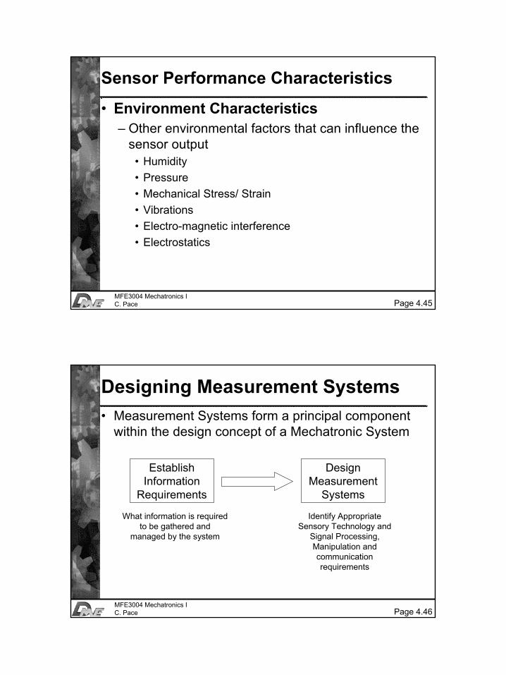
Sensor Performance Characteristics
• Environment Characteristics– Other environmental factors that can influence the
sensor output• Humidity• Pressure• Mechanical Stress/ Strain• Vibrations• Electro-magnetic interference• Electrostatics
Page 4.46MFE3004 Mechatronics IC. Pace
Designing Measurement Systems• Measurement Systems form a principal component
within the design concept of a Mechatronic System
Establish Information
Requirements
Design Measurement
Systems
What information is required to be gathered and
managed by the system
Identify Appropriate Sensory Technology and
Signal Processing, Manipulation and communication requirements
24
Page 4.47MFE3004 Mechatronics IC. Pace
Designing Measurement Systems• Consideration of the following factors
– The information required and the identification of the system physical parameters that must be measured in order to provide this information.
– The nature, quality and performance of the measurement in terms of parameters such as linearity, accuracy and resolution.
– A determination of the most inaccurate measurementthat would be acceptable (required accuracy)
– The effect on the system performance of any drift in the measurement circuit (zero or sensitivity)
Page 4.48MFE3004 Mechatronics IC. Pace
Designing Measurement Systems• Consideration of the following factors (continued)
– The environmental conditions under which the sensors are expected to operate
– The cost targets to be met
– The nature and form of the information transfer required
– The reliability of the system
– The form of the interface to adjacent modules in the system.

25
Page 4.49MFE3004 Mechatronics IC. Pace
Designing Measurement Systems
• When designing Measurement Systems care should be taken not to provide too much or too little information
– Too Much Information• Added cost• Added Processing burden
– Too Little Information• Inadequate Accuracy• Insufficient Update Rate• Lack of Desired Performance