Lecture Notes ELE-A6
35
4/24/2007 ELEC A6. Synchr. Machine • 1 Lecture Notes ELE-A6 Ramadan El-Shatshat Synchronous Machine
Transcript of Lecture Notes ELE-A6

4/24/2007 ELEC A6. Synchr. Machine• 1
Lecture NotesELE-A6
Ramadan El-Shatshat
Synchronous Machine

4/24/2007 ELEC A6. Synchr. Machine• 2
Classification ofAC Rotating Machines
• Synchronous Machines: • Synchronous Generators: A primary source of electrical energy.
• Synchronous Motors: Used as motors as well as power factor compensators (synchronous condensers).
• Asynchronous (Induction) Machines:• Induction Motors: Most widely used electrical motors in both
domestic and industrial applications.•• Induction Generators: Due to lack of a separate field excitation,
these machines are rarely used as generators.

4/24/2007 ELEC A6. Synchr. Machine• 3
SYNCHRONOUS MACHINES
Round Rotor Machine
• The stator is a ring shaped laminated iron-core with slots.
• Three phase windings are placed in the slots.
• Round solid iron rotor with slots.
• A single winding is placed in the slots. Dc current is supplied through slip rings.
Concept (two poles)
N S
A-B
+
A+ C
+
C-
B-
A
B
CStator with laminated iron-core
Slots withwinding
Rotor with dcwinding

4/24/2007 ELEC A6. Synchr. Machine• 4
Round Rotor Machine

4/24/2007 ELEC A6. Synchr. Machine• 5
SYNCHRONOUS MACHINES
Salient Rotor Machine• The stator has a laminated
iron-core with slots and three phase windings placed in the slots.
• The rotor has salient poles excited by dc current.
• DC current is supplied to the rotor through slip-rings and brushes.
• Concept (two poles)
N
S
A+
B+
C+B-
A-
C-

4/24/2007 ELEC A6. Synchr. Machine• 6
Salient Rotor Machine

4/24/2007 ELEC A6. Synchr. Machine• 7
SYNCHRONOUS GENERATOR
1) From an external source, the field winding is supplied with a DC current -> excitation.
2) Rotor (field) winding is mechanically turned (rotated) at synchronous speed.
3) The rotating magnetic field produced by the field current induces voltages in the outer stator (armature) winding. The frequency of these voltages is in synchronism with the rotor speed.
•Principle of Operation

4/24/2007 ELEC A6. Synchr. Machine• 8
SYNCHRONOUS MACHINES
Operation concept• The frequency - speed relation is f = (p / 120) n = p n /120
p is the number of poles.
• Typical rotor speeds are 3600 rpm for 2-pole, 1800 rpm for 4 pole and 450 rpm for 16 poles.
• The rms. value of the induced voltages is:
EA = 4.44 N BA f , (BA = φ)
• where:N = number of turns, B= flux density, A = cross sectional area of the magnetic circuit, f = frequency, and φ = flux per pole

4/24/2007 ELEC A6. Synchr. Machine• 9
Comparisons Between DC and Synchronous Machines

4/24/2007 ELEC A6. Synchr. Machine• 10
Synchronous GeneratorsEquivalent Circuit (round rotor)1) DC current in the field winding produces the main
flux, φf.2) φf induces an emf, EG, in the armature winding. 3) Depending on the load condition, the armature
current IA is established. In the following discussions, it is assumed to be a lagging power factor.
4) IA produces its own flux due to armature reaction, EARis the induced emf by φAR.
5) The resulting phasor, Eresultant = EG + EAR is the “true”induced emf that is available.

4/24/2007 ELEC A6. Synchr. Machine• 11
Synchronous GeneratorsEquivalent Circuit (round rotor)
Vt

4/24/2007 ELEC A6. Synchr. Machine• 12
Synchronous GeneratorsEquivalent Circuit (round rotor)
Phasor Diagrams:
where, (XAR + XA) = synchronous reactance, Xs.
( )V E I jX I jX I R E jX I I R
V E I R jXA A A A AR A A A s A A A
A A A s
φ
φ
= − − − = − −
= − +
Vt
Vt

4/24/2007 ELEC A6. Synchr. Machine• 13
Synchronous GeneratorsEquivalent Circuit (round rotor)
Inductive Load Resistive Load
= power angle

4/24/2007 ELEC A6. Synchr. Machine• 14
Power Supplied by a Synchronous Generator
)sin(3
)0)((03
3 *
δ
δ
s
ta
s
tat
At
XVEP
jXVEVS
IVjQPS
=
−∠−−∠
∠=
=+=

4/24/2007 ELEC A6. Synchr. Machine• 15
SYNCHRONOUS MACHINESPower angle Characteristics• The P(δ) curve shows that the
increase of power increases the angle between the induced voltage and the terminal voltage.
• The power is maximum when δ =90o
• The further increase of input power forces the generator out of synchronism. This generates large current and mechanical forces.
• The maximum power is the static stability limit of the system.
• Safe operation requires a 15-20% power reserve.
Round Rotor Machine
0 30 60 90 120 150 1800
20
40
60
80
100
P( )δ
δ
Pmax

4/24/2007 ELEC A6. Synchr. Machine• 16
Example 1
• A 25 kVA, 230 V three phase, four pole, 60 Hz, Y-connected synchronous generator has a synchronous reactance of 1.5 Ω/phase and a negligible resistance. The generator is connected to an open circuit of constant voltage (230 V) and frequency (60 Hz), find:
a) The generated EMF (EG) when the machine is delivering rated kVA at 0.8 power factor lagging.
b) If the field current If is increased by 20 % without changing the power input find the stator current Ia.

4/24/2007 ELEC A6. Synchr. Machine• 17

4/24/2007 ELEC A6. Synchr. Machine• 18

4/24/2007 ELEC A6. Synchr. Machine• 19
Voltage Regulation• As the load on the generator increases,
the terminal voltage drops. But, the terminal voltage, must be maintained constant, and hence the excitation on the machine is varied, or input power to the generator is varied. That means, EGhas to be adjusted to keep the terminal voltage Vt constant.
• Voltage Regulation, V. R. = V V
VNL FL
FL
−×100%

4/24/2007 ELEC A6. Synchr. Machine• 20
Calculate the percent voltage regulation for a three phase, Y-connected, 20 MVA ,13.8 kV synchronous generator operating at full load and 0.8 power factor lagging. The synchronous reactance is 8 ohm per phase and the armature resistance can be neglected.
Example 2

4/24/2007 ELEC A6. Synchr. Machine• 21
%7.647967
7967125,13:be willregulation voltatge theso ,V load, noAt
1.24125,13)(
9.367.836)8.0cos(8.133
1020)8.0cos(3
neutral) to(line 079673108.13
nl
3
3
=−
=−
=
=∠=++=
−∠=−∠×
=−∠=
∠=×
=
t
ta
a
saata
a
t
VVEVR
EjXRIVE
VSI
V

4/24/2007 ELEC A6. Synchr. Machine• 22
Measuring the Equivalent Circuit Parameters

4/24/2007 ELEC A6. Synchr. Machine• 23
Measuring the Equivalent Circuit Parameters
Measurement of RA:The winding resistance is measured by applying a DC voltage across the generator terminals under “stand-still”conditions. An equivalent value of the RA can then be calculated using the measured DC value.

4/24/2007 ELEC A6. Synchr. Machine• 24
Measuring the Equivalent Circuit Parameters
Measurement of Xs:
• (i) Open circuit test:• With the generator terminals open;
– Bring the generator to its rated speed.
– Increase the field current, IF, gradually from zero.
– Measure the open circuit terminal voltage, Vt(L-L.)
– Plot Vt(L-L.) as a function of IF. -> (OCC) Open Circuit Characteristic

4/24/2007 ELEC A6. Synchr. Machine• 25
Measuring the Equivalent Circuit Parameters
Measurement of Xs:
• (ii) short circuit test:• Bring the generator up to its
rated speed.
• .Increase IF gradually from zero and record ISC.Plot IF vs ISC on the original graph from test i.
• .This is the SCC Short Circuit Characteristic.

4/24/2007 ELEC A6. Synchr. Machine• 26
Measuring the Equivalent Circuit Parameters
Measurement of Xs:
In many cases Rs
can be ignored.IF
Isc
Z R XEIs A s
A
A cons t I
OC
SC F
= + =2 2
tan

4/24/2007 ELEC A6. Synchr. Machine• 27
Parallel Operation of Synchronous Generators
• Generators are rarely used in isolated situations. More commonly, generators are used in parallel, often massively in parallel, such as in the power grid. The following steps must beadhered to:
• when adding a generator to an existing power grid:1) RMS line voltages of the two generators must be the same.2) Phase sequence must be the same.3) Phase angles of the corresponding phases must be the same.4) Frequency must be the same.

4/24/2007 ELEC A6. Synchr. Machine• 28
SYNCHRONOUS Motors
• 1) From an external DC source, the field winding is supplied with a DC current -> excitation.
• 2) Outer stator winding is supplied with a three phase voltage which produces a rotating magnetic field.
• 3) The rotor’s magnetic field produced by the field current (hence the rotor) will tend to line-up with the rotating magnetic field produced by the stator’s 3-phase currents. However, synchronous motors are not “self-starting”motors. A mechanism is needed to put the rotor in synchronism with the RMF.
•Principle of Operation

4/24/2007 ELEC A6. Synchr. Machine• 29
Synchronous MotorEquivalent Circuit
Phasor Diagrams:
aaasat IRIjXEV ++=

4/24/2007 ELEC A6. Synchr. Machine• 30
Synchronous MotorEquivalent Circuit
Where θ is the angle between Vt and Ia and δis the angle between Vt and Ea

4/24/2007 ELEC A6. Synchr. Machine• 31
Effect of field current changes
• When If increases, Ea will increase.
• Since there is no change in the output power and Vt, both Ia*cos(θ) and Ea*sin(δ) will be constant.
• As a result, the power factor will change as we change the field current

4/24/2007 ELEC A6. Synchr. Machine• 32
Q1

4/24/2007 ELEC A6. Synchr. Machine• 33
Q1
4/24/2007 ELEC A6. Synchr. Machine• 34
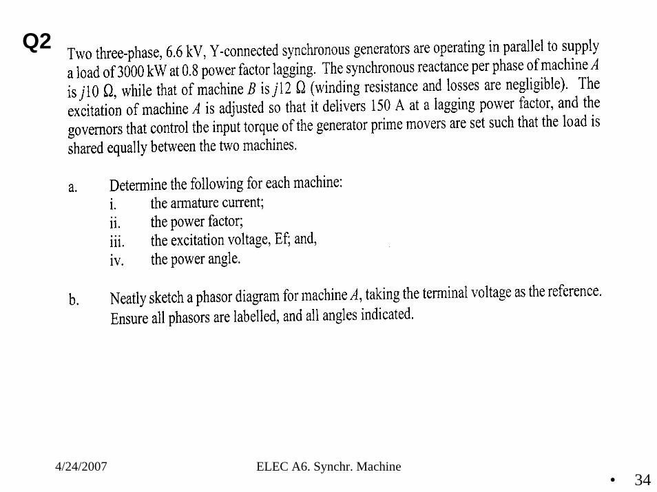
Q2

4/24/2007 ELEC A6. Synchr. Machine• 35
Q3