Lecture Notes Aerodynamics Introductory
30
1 Dr. Abdullah M. Al-Garni AE Dept., KFUPM A er o d y nam i c s: In t ro d u c t i on • Aerodynamics dea ls with the motion of objects in air. These obj ects can be airplanes, missiles or road vehicles. • The Table below summarizes the aspects of vehicle perfo rmance directly influenced by aerodynamic design. Splash and Spray Dirt Accumulation Visibility Wind Noise Heating, Ventilation and Air Conditioning Comfort Condenser Brakes Transmission Engine Cooling Crosswind Sensitivity Response to Flow Unsteadiness Directional Stability Stability Acceleration Maximum Speed Emissions Fuel Economy Performance
-
Upload
veeramani-shankar -
Category
Documents
-
view
225 -
download
0
Transcript of Lecture Notes Aerodynamics Introductory

7/22/2019 Lecture Notes Aerodynamics Introductory
http://slidepdf.com/reader/full/lecture-notes-aerodynamics-introductory 1/30
1 Dr. Abdullah M. Al-Garni AE Dept., KFUPM
Aerodynamics: Introduction• Aerodynamics deals with the motion of objects in air. These objects
can be airplanes, missiles or road vehicles.
• The Table below summarizes the aspects of vehicle performance
directly influenced by aerodynamic design.
Splash and Spray
Dirt AccumulationVisibility
Wind Noise
Heating, Ventilation and Air ConditioningComfort
Condenser
Brakes
Transmission
Engine
Cooling
Crosswind Sensitivity
Response to Flow Unsteadiness
Directional Stability
Stability
Acceleration
Maximum Speed
Emissions
Fuel Economy
Performance

7/22/2019 Lecture Notes Aerodynamics Introductory
http://slidepdf.com/reader/full/lecture-notes-aerodynamics-introductory 2/30
2 Dr. Abdullah M. Al-Garni AE Dept., KFUPM
Aerodynamics: Aerodynamic Forces
• When a body moves in the air, a
pressure and shear (friction)
stresses are produced at every
point of the body.
• The pressure, p, acts normal to
the surface and the shear, τ , acts
tangential to the surface of the
body.
• The sum of the pressure and shear
forces gives the resultant force, R .
• The aerodynamic forces are mainly
due to pressure and shear stress
distribution over the body surface.
τ
p
V ∞ Airfoil

7/22/2019 Lecture Notes Aerodynamics Introductory
http://slidepdf.com/reader/full/lecture-notes-aerodynamics-introductory 3/30
3 Dr. Abdullah M. Al-Garni AE Dept., KFUPM
Aerodynamics: Aerodynamic Forces
• The resultant force, R , can be resolved into twocomponents along the wind (freestream) axes:
lift = L = component normal to V ∞
drag = D = component along V ∞
or along the body axes axis:
normal force = N = component normal to the airfoil chord
axial force = A = component along the body chord
• The point at which the resultant force acts is called the
center of pressure.
• It is convenient sometimes to specify the aerodynamic
center which is defined as the point at which the
aerodynamic moment, M , is independent of the angle of
attack, α.
N R
V ∞ A
L
D
α
chord line M
7/22/2019 Lecture Notes Aerodynamics Introductory
http://slidepdf.com/reader/full/lecture-notes-aerodynamics-introductory 4/30
4 Dr. Abdullah M. Al-Garni AE Dept., KFUPM
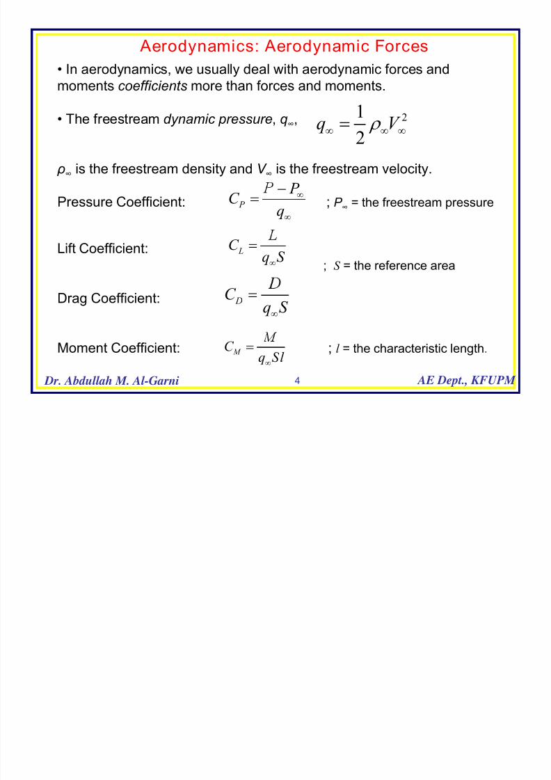
Aerodynamics: Aerodynamic Forces
• In aerodynamics, we usually deal with aerodynamic forces andmoments coefficients more than forces and moments.
• The freestream dynamic pressure, q∞,
ρ∞ is the freestream density and V ∞ is the freestream velocity.
Pressure Coefficient: ; P ∞ = the freestream pressure
Lift Coefficient:
; S = the reference area
Drag Coefficient:
Moment Coefficient: ; l = the characteristic length.
21
2q V ρ
∞ ∞ ∞=
P
P C
q∞
∞
−=
LC q S
∞
=
DC q S ∞
=
M C q Sl
∞
=

7/22/2019 Lecture Notes Aerodynamics Introductory
http://slidepdf.com/reader/full/lecture-notes-aerodynamics-introductory 5/30
5 Dr. Abdullah M. Al-Garni AE Dept., KFUPM
Aerodynamics: Aerodynamic Forces
From dimensional analysis, the above coefficients depend on some parameters:
• Mach number , M = V ∞ /a where a is the speed of sound.
• Reynolds number , Re = ρV ∞ l / μ where ρ is the air density and μ is the dynamic
viscosity of the air.
• Angle of attack , α .
• In many practical problems, the lift, drag and moment coefficients are identical
for geometrically similar bodies at the same Mach, Reynolds number and angle ofattack.
(C L)1 = (C L)2
(C D)1 = (C D)2
(C M )1 = (C M )2
1 2
7/22/2019 Lecture Notes Aerodynamics Introductory
http://slidepdf.com/reader/full/lecture-notes-aerodynamics-introductory 6/30
6 Dr. Abdullah M. Al-Garni AE Dept., KFUPM
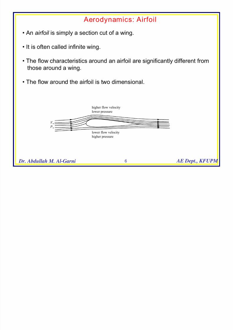
Aerodynamics: Airfoil
• An airfoil is simply a section cut of a wing.
• It is often called infinite wing.
• The flow characteristics around an airfoil are significantly different fromthose around a wing.
• The flow around the airfoil is two dimensional.
lower flow velocity
higher pressure
V ∞ P ∞
higher flow velocity
lower pressure

7/22/2019 Lecture Notes Aerodynamics Introductory
http://slidepdf.com/reader/full/lecture-notes-aerodynamics-introductory 7/30
7 Dr. Abdullah M. Al-Garni AE Dept., KFUPM
Aerodynamics: Airfoil
• The pressure and velocity fieldsaround the airfoil are related via
the Bernoulli’s equation
• The pressure distribution over
Joukowski airfoil at α = 10º.
• The pressure coefficient isnegative (means lower than the
freestream pressure, P ∞) over the
top surface and positive (higher
than the freestream pressure, P ∞)
on the bottom surface of the airfoil.
• The net imbalance of pressure
distribution produces the lift.
lower flow velocity
higher pressure
V ∞ P ∞
higher flow velocitylower pressure
2 21 12 2
P V P V ρ ρ ∞ ∞
+ = +
0 0.2 0.4 0.6 0.8 1
-5
-4
-3
-2
-1
0
1
C p
x/c

7/22/2019 Lecture Notes Aerodynamics Introductory
http://slidepdf.com/reader/full/lecture-notes-aerodynamics-introductory 8/30
8 Dr. Abdullah M. Al-Garni AE Dept., KFUPM
Aerodynamics: Wings
• Often called finite wing
• The flow around a wing is three
dimensional; there is a flow in the
spanwise direction.
• The mechanism for generating lift is the
same as that for the airfoil, a higher
pressure on the bottom surface and a
lower pressure over the top surface.
• As consequence of the pressure
imbalance between the lower and upper
surface of the wing, the flow near the
wing tips tends to curl around the tips; the
flow is forced from the higher pressureregion just underneath the wing tips to
the lower pressure region on the top of
the wing.
Flow from higher pressure
region (lower surface) tolower pressure region (upper
surface)
•This causes the flow underneath thewing to move along the spanwise
direction from the wing root to the tip
and the flow on top of the wing to move
from the wing tip to the root.

7/22/2019 Lecture Notes Aerodynamics Introductory
http://slidepdf.com/reader/full/lecture-notes-aerodynamics-introductory 9/30
9 Dr. Abdullah M. Al-Garni AE Dept., KFUPM
Aerodynamics: Wings
• This flow produced a trailing vortex at both wing tips that trails
downstream of the wing.
• For large airplanes such as the
Boeing 747, these vortices arepowerful enough to cause light
airplanes flying closely behind to go
out of control.
• Accidents due to these vorticeshave occurred and that is one of the
reasons for large spacing between
aircraft during landing and take-off at
airports.
• The vortices draw the air behind the
wind thus inducing a downwash
(downward flow) in the neighborhood
of the wing.
Top view Cross section view

7/22/2019 Lecture Notes Aerodynamics Introductory
http://slidepdf.com/reader/full/lecture-notes-aerodynamics-introductory 10/30
10 Dr. Abdullah M. Al-Garni AE Dept., KFUPM
Aerodynamics: Flow Characteristics for Wings
• This downwash results in an increase ofdrag.
• The additional drag is called induced drag,
Di , and is related to the lift by
• The downwash also affects the angle of
attack.The angle of attack actually seen by the
wing is the angle between the chord line
and the local relative wind defined as the
effective angle of attack , α eff .
• The “geometric angle of attack” α and the
“aerodynamic angles of attack” α eff and α i is
given by
Di
V ∞
L
α
αi
αeff
αi
wV ∞
Local relative
wind
Chord linesini i D L α =
eff i
α α α = −

7/22/2019 Lecture Notes Aerodynamics Introductory
http://slidepdf.com/reader/full/lecture-notes-aerodynamics-introductory 11/30
11 Dr. Abdullah M. Al-Garni AE Dept., KFUPM
Aerodynamics: Lift on Airfoil
• At small angles of attack thelift coefficient varies linearly
with the angle of attack for
both symmetric and cambered
airfoils.
• The mathematical analysis
shows that for a symmetric
airfoil
•for a cambered airfoil :
•The slopes of the lift
coefficient for symmetric and
cambered airfoils are the
same.
Cambered airfoil
Symmetric airfoil at small α
Symmetric airfoil at high α
α L=0 =0
α L=0 < 0
α
C l
2l C πα =
02 ( )l LC π α α =
= −
/ 2o l dC d η α π = =
l o
dC
d η
α =

7/22/2019 Lecture Notes Aerodynamics Introductory
http://slidepdf.com/reader/full/lecture-notes-aerodynamics-introductory 12/30
12 Dr. Abdullah M. Al-Garni AE Dept., KFUPM
Aerodynamics: Lift on Airfoil
Cambered airfoil
Symmetric airfoil at small α
Symmetric airfoil at high α
α L=0 =0
α L=0 < 0
α
C l
l o
dC
d η
α =
• As the angle of attack
increases, an adverse pressure
gradient starts to develop over
the top surface of the airfoilwhich will cause the boundary
layer to separate.
• At a certain angle of attack, this
adverse pressure becomesstrong enough to cause flow
separation over the top surface
of the airfoil.
• Once the flow separates the liftcoefficient drop drastically and as
a consequence stall occurs as
shown in Figure 9.

7/22/2019 Lecture Notes Aerodynamics Introductory
http://slidepdf.com/reader/full/lecture-notes-aerodynamics-introductory 13/30
13 Dr. Abdullah M. Al-Garni AE Dept., KFUPM
Aerodynamics: Lift on Wing
• The lift curve for a wing has smaller slope than the corresponding lift curve foran airfoil with the same airfoil cross section.
• The relationship between the two slopes is given by
where η is the slope of a wing, ηo is the slope of the airfoil, is the aspect ratio,
τ is a correction factor.
• The aspect ration is defined as where b is the span and S is the
area of the wing.
1 (1 )
L o
o
dC d
η η
η α τ
π
= =
+ +ℜ
2 /b S ℜ =

7/22/2019 Lecture Notes Aerodynamics Introductory
http://slidepdf.com/reader/full/lecture-notes-aerodynamics-introductory 14/30
14 Dr. Abdullah M. Al-Garni AE Dept., KFUPM
Aerodynamics: Lift and Circulation
• The lift per unit span of an airfoil can be related to the intensity of thecirculatory flow or circulation, Γ, via Kutta-Joukowski Theorem
where the L′ is the lift per unit span of the wing.
• This relation shows that the lift per unit span is directly proportional to
circulation.
• It is a pivotal relation in ideal incompressible flow theory often called
potential flow theory.
•Thus, a major propel of the potential flow theory is to calculate circulation.
' L V ρ ∞ ∞
= Γ

7/22/2019 Lecture Notes Aerodynamics Introductory
http://slidepdf.com/reader/full/lecture-notes-aerodynamics-introductory 15/30
15 Dr. Abdullah M. Al-Garni AE Dept., KFUPM
Aerodynamics: Lift and Circulation
• Example of this relation:
flow over a circular cyl inder
• The flow around non-lifting
circular cylinder is symmetric
• Hence one would expect that
the pressure distribution over the
top and bottom surfaces of the
cylinder is also symmetric.
•This results in zero lift for the
cylinder.
•However, if the cylinder rotatesabout its axis, then the flow field
is not symmetric any more.
Flow over Non-lifting circular cylinder
Flow over lifting circular cylinder
L = 0
L > 0

7/22/2019 Lecture Notes Aerodynamics Introductory
http://slidepdf.com/reader/full/lecture-notes-aerodynamics-introductory 16/30
16 Dr. Abdullah M. Al-Garni AE Dept., KFUPM
Aerodynamics: Lift and Circulation
• Why do we have a lift when the cylinderrotates?.
• When the cylinder rotates, this will
increase the flow velocity over the top
surface and decrease it on the bottomof the cylinder.
• As a result, the pressure on the top
surface decreases and the pressure on
the bottom surface increases(Bernoulli’s equation).
•This net imbalance of pressure will
produce a finite lift as sketched in
Figure. This is often called Magnus
effect.
Flow over lifting circular cylinder
L > 0
High speed flow
Low pressure
Low speed flow
High Pressure
V ∞
ω
L′
2 21 1
2 2
P V P V ρ ρ ∞ ∞
+ = +

7/22/2019 Lecture Notes Aerodynamics Introductory
http://slidepdf.com/reader/full/lecture-notes-aerodynamics-introductory 17/30
17 Dr. Abdullah M. Al-Garni AE Dept., KFUPM
Aerodynamics: Lift and Circulation
• Another Example of this relation:
flow over a airfoi l with a
leading-edge rotating cylinder
Leading-edge cylinder is off [α = 0]a) U c /U = 0
b) U c /U = 1
L > 0
L = 0
0
0.2
0.4
0.6
0.8
1
1.2
1.4
1.6
1.8
0 5 10 15 20 25 30 35 40
α
o
C L
Uc/U=0
Uc/U=1
Uc/U=2
Uc/U=3
Uc/U=4
Leading-edge cylinder rotates

7/22/2019 Lecture Notes Aerodynamics Introductory
http://slidepdf.com/reader/full/lecture-notes-aerodynamics-introductory 18/30
18 Dr. Abdullah M. Al-Garni AE Dept., KFUPM
Aerodynamics: Lift and Circulationa) U c /U = 0
b) U c /U = 1
α = 20
e) U c /U = 4

7/22/2019 Lecture Notes Aerodynamics Introductory
http://slidepdf.com/reader/full/lecture-notes-aerodynamics-introductory 19/30
19 Dr. Abdullah M. Al-Garni AE Dept., KFUPM
δ
C L
Wing with a trailing-edge flap
Wing without flap and slat
Wing with a leading-edge slat
α
d i n
c r e a s e
s
Aerodynamics: High Lift Devices
• The lifting properties of a givenairfoil can be enhanced by using high
lift devices as shown in the Figure 13.
• The most common of these devices
is the simple flap at the trailing edgeof the wing.
• When the flap is deflected
downward, the camber of the airfoil is
increased.
• This increase is associated with a
dramatic increase in the maximum lift
coefficient, C L,max and a shift of the
zero-lift angle of attack to a morenegative value for the wing.

7/22/2019 Lecture Notes Aerodynamics Introductory
http://slidepdf.com/reader/full/lecture-notes-aerodynamics-introductory 20/30
20 Dr. Abdullah M. Al-Garni AE Dept., KFUPM
Aerodynamics: High Lift Devices
• In some airplanes, the flap is designednot only to deflect downward but also to
translate rearward which increases the
wing area and hence increase the lift.
• The flap can increase the maximum liftcoefficient by about 200%.
• High lift devices can also be applied to
the leading edge of the wing with the most
common is the leading-edge slat.
• The leading edge slat can alter the
pressure distribution over the wing, reduce
the pressure on the top and increase the
pressure on the bottom surface. As aresult, a more lift is generated on the wing.
•Another advantage of the leading-edge
slat is the delay of flow separation over
δ
C L
Wing with a trailing-edge flap
Wing without flap and slat
Wing with a leading-edge slat
α
d i n
c r e a s e
s
the top surface of the wing to higherangles of attack and consequently delays
stall of the wing. In modern aircraft a
combination of leading-edge slat and
trailing-flaps is common.

7/22/2019 Lecture Notes Aerodynamics Introductory
http://slidepdf.com/reader/full/lecture-notes-aerodynamics-introductory 21/30
21 Dr. Abdullah M. Al-Garni AE Dept., KFUPM
Aerodynamics: Drag
• The drag is an important subject in aerodynamics.
•A reduction in drag can lead to a reduction in fuel consumption and better
performance for a vehicle.
•The drag coefficient varies from one object to another depending on the
particular geometry of that object.
•For streamlined body such as wing and airfoil, the drag coefficient is lowcompared to bluff body such as circular cylinder, sphere or road vehicle.

7/22/2019 Lecture Notes Aerodynamics Introductory
http://slidepdf.com/reader/full/lecture-notes-aerodynamics-introductory 22/30
22 Dr. Abdullah M. Al-Garni AE Dept., KFUPM
Aerodynamics: Drag
C D
= 0.017Boeing 747
C D
= 0.037Piper PA-16
Clipper
C D
= 0.4-0.5Pickup
truck
C D
= 1.6Equilateral
triangle
C D = 1.7
Half
Cylinder
C D
= 1.2Half
Cylinder
C D
= 0.12Streamlined
body
C D
= 1.2 at Re =
105
C D
= 0.6 at Re =
107
Circular
Cylinder
C D
= 2.0 Normal
Plate
V ∞
d
V ∞
d
V ∞
d
V ∞
d
V ∞
d
V ∞ d
X
Z

7/22/2019 Lecture Notes Aerodynamics Introductory
http://slidepdf.com/reader/full/lecture-notes-aerodynamics-introductory 23/30
23 Dr. Abdullah M. Al-Garni AE Dept., KFUPM
Aerodynamics: Drag for Airfoil vs. Wing
• It is important to note that there is a difference between the drag of an airfoil andthat of a wing.
• The drag acting on an airfoil section is the sum of the skin friction drag , Df , and
the pressure drag , D p, which is due to flow separation. That is,
The sum of the skin friction drag and the pressure drag is called profile drag .
• On the other hand, the total drag of a subsonic finite wing in a real case is the
sum of the induced drag, Di , and the profile drag,
where the subscript D represents the drag of the wing and the subscript d
represent the drag of the airfoil.
f p
d
DC
q S ∞
+=
i
D d
D
C C q S ∞
= +

7/22/2019 Lecture Notes Aerodynamics Introductory
http://slidepdf.com/reader/full/lecture-notes-aerodynamics-introductory 24/30
24 Dr. Abdullah M. Al-Garni AE Dept., KFUPM
Aerodynamics: Drag for Airfoil vs. Wing
• Using the lifting line theory it can be shown that for ageneral wing
where is the induced drag coefficient and e is the
span efficiency factor . For elliptical wing, e = 1 and forother platforms, e < 1.
• Therefore, the induced drag is minimum for an
elliptical platform.
• In the past, several aircraft have been designed with
elliptical wings.
• However, elliptical wings are more expensive to
manufacture than other simple platform such asrectangular wings. The rectangular wing is
considered far from optimum. A compromise between
the elliptical wing (manufacturing difficulty) and
rectangular wing (poor efficiency) is the tapered wing.
2
, L
D i
C C
eπ =
ℜ
Tapered wing
Rectangular wing
Elliptic wing

7/22/2019 Lecture Notes Aerodynamics Introductory
http://slidepdf.com/reader/full/lecture-notes-aerodynamics-introductory 25/30
25 Dr. Abdullah M. Al-Garni AE Dept., KFUPM
Aerodynamics: Laminar and Turbulent Flows
• The drag coefficient of a body depends on theflow around the body whether it is laminar or
turbulent.
• When the streamlines are smooth and regular and
a fluid element moves smoothly along a streamline
the flow is called laminar.
• On the other hand, when the streamlines break up
and a fluid element moves in a random, irregular,
and tortuous fashion the flow is called turbulent.
• Most of real flows are turbulent flows.
•In turbulent flow, the higher energy fluid elements
from the outer regions of the flow are pumped close
to the surface. Hence, the average flow velocity
near a solid surface is larger for a turbulent flow incomparison with laminar flow. Figure 15 shows the
velocity profile for laminar and turbulent boundary
layers.
Laminar flow
Turbulent flow

7/22/2019 Lecture Notes Aerodynamics Introductory
http://slidepdf.com/reader/full/lecture-notes-aerodynamics-introductory 26/30
26 Dr. Abdullah M. Al-Garni AE Dept., KFUPM
Aerodynamics: Laminar and Turbulent Flows
• In turbulent flow, the higher energy fluid elements
from the outer regions of the flow are pumped close
to the surface.
• Hence, the average flow velocity near a solid
surface is larger for a turbulent flow in comparisonwith laminar flow.
• Since the shear stress is proportional to the
velocity gradient along the y-direction
then the shear stress (friction) as well asaerodynamic heating at the wall surface is higher for
turbulent flow than laminar flow.
Turbulent
L a m
i n a r
y
u
/u yτ ∝ ∂ ∂

7/22/2019 Lecture Notes Aerodynamics Introductory
http://slidepdf.com/reader/full/lecture-notes-aerodynamics-introductory 27/30
27 Dr. Abdullah M. Al-Garni AE Dept., KFUPM
Aerodynamics: Streamlined vs. Bluff body
• Airfoils, flat plate and wings are considered to be
streamlined bodies. On the other hand, cylinder,
sphere, trucks are bluff bodies.
• The flow around streamlined and bluff bodies is
significantly different.
• The flow over streamlined body is usuallysmooth and the wake behind the body is small.
• The flow over bluff body, however, exhibits a
large wake downstream the body. This wake iscaused by separating flow from the body surface
with a low-energy recirculating flow inside the
wake as shown in the figure below.
Streamlined body- small wake
Bluff body- large wake

7/22/2019 Lecture Notes Aerodynamics Introductory
http://slidepdf.com/reader/full/lecture-notes-aerodynamics-introductory 28/30
28 Dr. Abdullah M. Al-Garni AE Dept., KFUPM
Aerodynamics: Streamlined vs. Bluff body
• The skin friction drag is due to the shear forces
acting on the body and the pressure drag is due
to flow separation from the body surface.
• Therefore, if the body is streamlined, the flow
separation is minimal and one would expect thatthe friction drag is much greater than the pressure
drag.
• Since skin friction drag is smaller for laminar
than for turbulent flow, laminar flow is desirablefor streamlined bodies.
•On the other hand, the pressure drag which is
due to flow separation is much greater for bluff
body than skin friction drag.
•In this case, the turbulent flow is desirable
because the pressure drag for turbulent flow is
smaller than for laminar flow.
p D
p f D D
Laminar f low is desirable
Turbulent f low is desirable
7/22/2019 Lecture Notes Aerodynamics Introductory
http://slidepdf.com/reader/full/lecture-notes-aerodynamics-introductory 29/30
29 Dr. Abdullah M. Al-Garni AE Dept., KFUPM
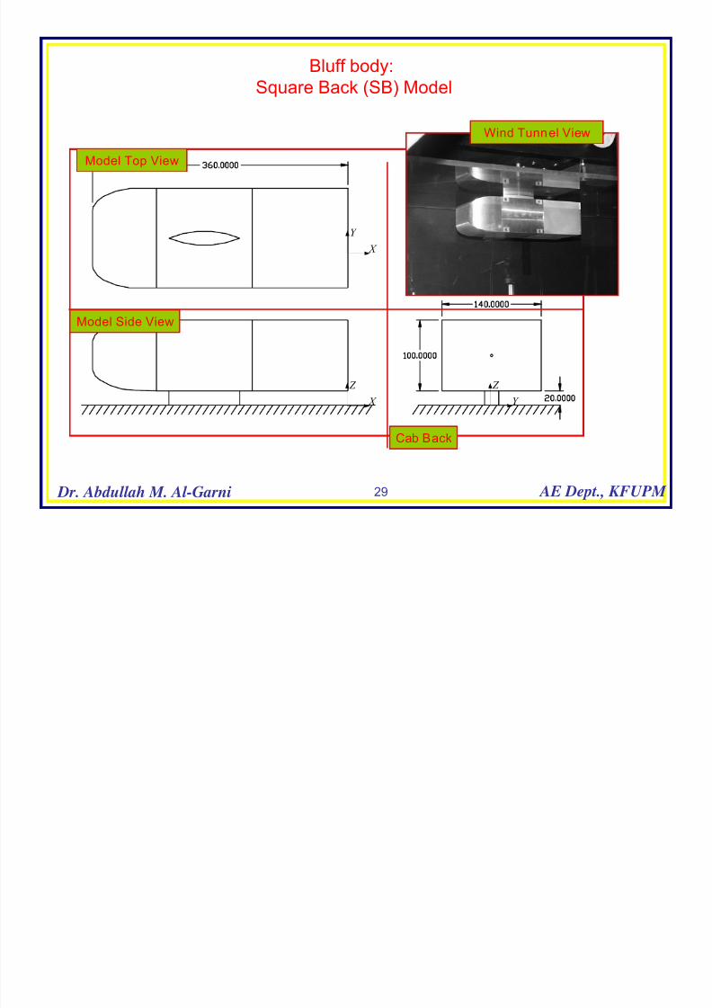
Bluff body:
Square Back (SB) Model
X
Y
X Z
Y Z
Model Side View
Model Top View
Cab Back
Wind Tunnel View

7/22/2019 Lecture Notes Aerodynamics Introductory
http://slidepdf.com/reader/full/lecture-notes-aerodynamics-introductory 30/30
30 Dr. Abdullah M. Al-Garni AE Dept., KFUPM
PIV Results
0 50 100 150 200 250
-100
-80
-60
-40
-20
0
20
40
60
80
100
x (mm)
y ( m m )
0 50 100 150 200 250
-100
-80
-60
-40
-20
0
20
40
60
80
100
x (mm)
y ( m m )
U = 30 m/s
Mean velocity and vorticity Fields Streamlines of the mean velocity field