External Thermal Insulation Composite System Insulation below
Lecture 7Thermal Insulation & Cryostat Basics
J. G. Weisend II
Summer 2021
Lecture 7| Thermal Insulation & Cryostat Basics- J. G. Weisend II
1

Goals
▪ Introduce conduction, convection & radiation heat transfer as they apply to cryogenics
▪ Describe design techniques to reduce heat transfer into cryogenic devices
▪ Allow the estimating and scaling of heat leaks into cryogenic devices
▪ Discuss the basics of cryostat design
▪ Warning! Not a full description of heat transfer• Many topics (boiling, detailed convection calculations, complicated
geometries in radiation heat transfer etc) won’t be covered• Should, however, be a good example of how heat transfer theory can be
applied to practical problems.
Summer 2021
Lecture 7| Thermal Insulation & Cryostat Basics- J. G. Weisend II
Slide 2

Three Ways to Transfer Heat
▪ Conduction
• Heat transfer through solid material
▪ Convection
• Heat transfer via a moving fluid»Natural or free convection – motion caused by gravity (i.e. density changes)
» Forced – motion caused by external force such as a pump
▪ Radiation• Heat transferred by electromagnetic radiation/photons
▪ There is no such thing as a perfect insulator – though we can design systems with very small heat leaks
▪ All matter above 0 K radiate heat
• Remember we can’t get to 0 K – 3rd Law of Thermodynamics though we can get vanishingly close
▪ Heat flows from high temperature to low
• Heat leaks in, cold doesn’t leak out
Summer 2021
Lecture 7| Thermal Insulation & Cryostat Basics- J. G. Weisend II
Slide 3
Conduction Heat Transfer
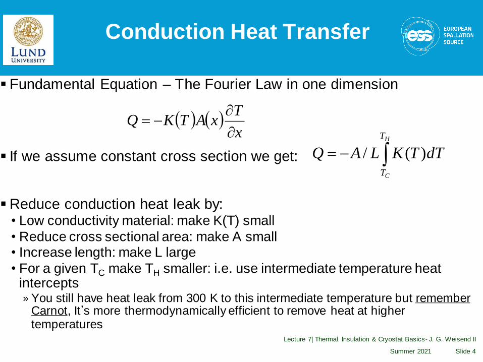
▪ Fundamental Equation – The Fourier Law in one dimension
▪ If we assume constant cross section we get:
▪ Reduce conduction heat leak by:• Low conductivity material: make K(T) small
• Reduce cross sectional area: make A small• Increase length: make L large
• For a given TC make TH smaller: i.e. use intermediate temperature heat intercepts» You still have heat leak from 300 K to this intermediate temperature but remember
Carnot, It’s more thermodynamically efficient to remove heat at higher temperatures
Summer 2021
Lecture 7| Thermal Insulation & Cryostat Basics- J. G. Weisend II
Slide 4
( ) ( )x
TxATKQ
−=
−=H
C
T
T
dTTKLAQ )(/

Design Example ILC Cryomodule Support Post
Summer 2021
Lecture 7| Thermal Insulation & Cryostat Basics- J. G. Weisend II
Slide 5
▪ Total Heat Leak (conduction & radiation)• 70 K - 10.5 W• 5 K - 0.9 W
• 2 K - 0.03 W
▪ Can support up to 50 kN
300 K
70 K
4 K
2 K
Fiberglass pipe
Courtesy T. Nicol - Fermilab

Conduction Heat Transfer
▪ Conduction heat leaks may be estimated by the use of Thermal Conductivity Integrals (Lecture 4)
Summer 2021
Lecture 7| Thermal Insulation & Cryostat Basics- J. G. Weisend II
Slide 6
( )21 −−= GQ

Convection Heat Transfer
▪ Fundamental Equation: Newton’s law of cooling
Q = hA(Tsurface – Tfluid)
where h is the heat transfer coefficient and is a function of Re, Pr, geometry etc depending on the situation
▪ In cryogenics we eliminate convection heat leak in cryogenic systems by “simply” eliminating the fluid – vacuum insulation
▪ Using vacuum insulation to create vessels capable of storing cryogenic liquids was first done by James Dewar – who liquefied hydrogen• Such vessels are frequently called dewars – though not always, more later• Thermos bottles are a simple example of this approach
Summer 2021
Lecture 7| Thermal Insulation & Cryostat Basics- J. G. Weisend II
Slide 7

Design Example Vacuum Insulated Test Cryostat
Summer 2021
Lecture 7| Thermal Insulation & Cryostat Basics- J. G. Weisend II
Slide 8
▪ Contains 3 Vacuum Spaces• 1 between 300 K wall and LN2 bath
• 1 between LN2 bath and LHe bath• 1 between LHe bath and
experiment

Vacuum Insulation
▪ How much vacuum is enough?• This of course depends on the heat leak requirements but generally we want
to be below 10-5 torr If we maintain this level or better we can generally neglect the convection heat leak for most applications. »Cryogenic Engineering, Flynn (1997) has a good discussion of calculating heat
leak due to residual gas pressure
▪ Cryopumping• At cryogenic temperatures almost all common gases condense and freeze
onto the cold surface. Typically, we’ll see that once surface are cooled to ~ 77 K the isolation vacuum will drop to the 10-8 torr or better range if the system is leak tight and doesn’t have significant outgassing
• But don’t just start cooling with everything at room pressure»Heat leak will likely be too high
» Safety hazards due to enrichment of LOX on cold surfaces
» Large amounts of condensed gases in vacuum space can lead to other problems including rapid pressure rise upon warming and possible solid conduction
» Best practice is to be at least 10-3 torr before cooling, lower pressures are better but there may be operational tradeoffs
Summer 2021
Lecture 7| Thermal Insulation & Cryostat Basics- J. G. Weisend II
Slide 9

Outgassing and Getters
▪ All material outgas into a vacuum. This can raise the pressure in a sealed vacuum space
▪ Reduce outgassing by:• Minimize amount of polymers, wire insulation, FRP etc – difficult
• Keep vacuum surfaces as clean as possible. Remove any oil or cutting fluid, wear gloves etc.
▪ Getters: materials inserted into vacuum spaces to remove residual gas at low pressures
▪ In cryogenic systems, getters may be useful in removing residual gas and passively managing small leaks
Summer 2021
Lecture 7| Thermal Insulation & Cryostat Basics- J. G. Weisend II
Slide 10
Outgassing and Getters
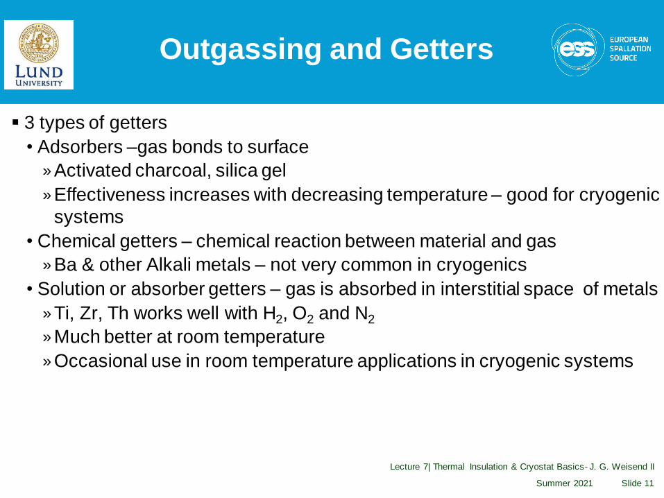
▪ 3 types of getters
• Adsorbers –gas bonds to surface
»Activated charcoal, silica gel
»Effectiveness increases with decreasing temperature – good for cryogenic
systems
• Chemical getters – chemical reaction between material and gas
»Ba & other Alkali metals – not very common in cryogenics
• Solution or absorber getters – gas is absorbed in interstitial space of metals
»Ti, Zr, Th works well with H2, O2 and N2
»Much better at room temperature
»Occasional use in room temperature applications in cryogenic systems
Summer 2021
Lecture 7| Thermal Insulation & Cryostat Basics- J. G. Weisend II
Slide 11
Getters, Cryogenics and Gilligan’s island
▪ It turns out that one of the most common and effective materials used for getters of low pressure He gas is activated charcoal made from coconut husks.
▪ There is a significant amount of this material in the LHC magnet cryostats
Summer 2021
Lecture 7| Thermal Insulation & Cryostat Basics- J. G. Weisend II
Slide 12
The Professor says:
“Lets look for the Higgs!”
Foam & Other Insulation Methods
▪ Not all cryogenic systems use vacuum insulation
▪ This is particularly true of storage vessels for fluids other than helium
▪ Reasons for using alternatives to vacuum insulation• Cost
• Weight – Space shuttle main tank• Required hold time – related to size
• Complex vessel shapes
▪ Some solutions• Expanded closed or open cell foams• Rock wool, fiberglass or other porous material
▪ These all require vapor barriers to prevent air from being pulled into the insulation and condensed (can cause both a safety hazard via O2
enrichment & reduce effectiveness)
Summer 2021
Lecture 7| Thermal Insulation & Cryostat Basics- J. G. Weisend II
Slide 13
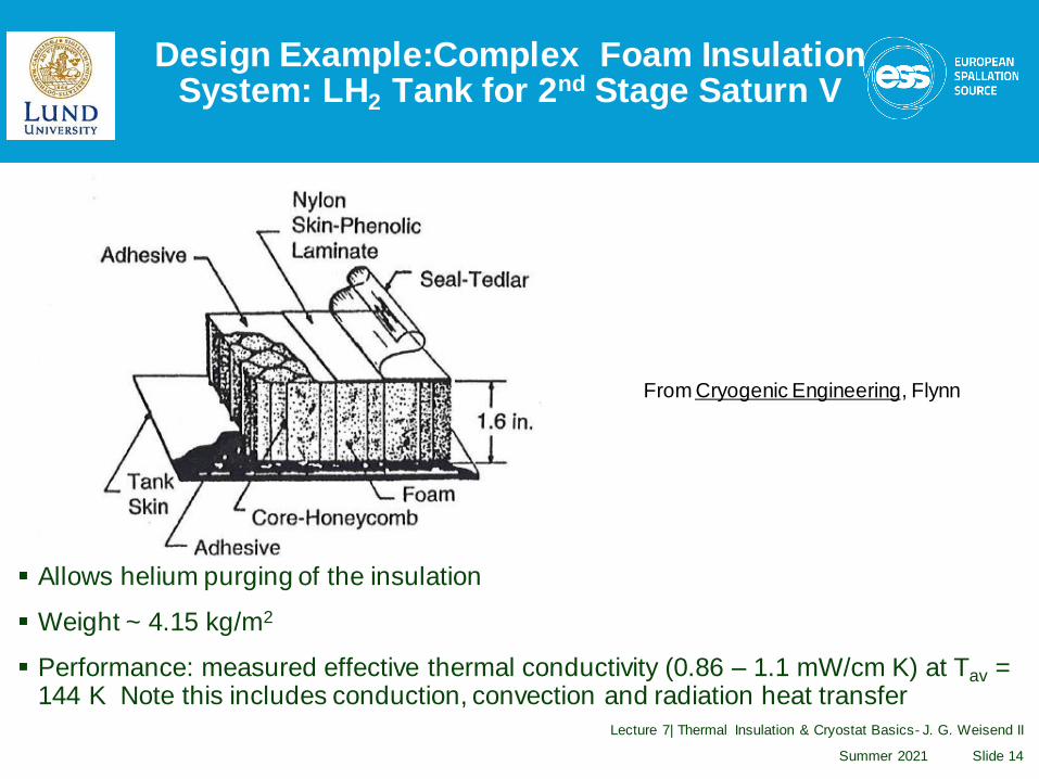
Design Example:Complex Foam Insulation System: LH2 Tank for 2nd Stage Saturn V
Summer 2021
Lecture 7| Thermal Insulation & Cryostat Basics- J. G. Weisend II
Slide 14
▪ Allows helium purging of the insulation
▪ Weight ~ 4.15 kg/m2
▪ Performance: measured effective thermal conductivity (0.86 – 1.1 mW/cm K) at Tav = 144 K Note this includes conduction, convection and radiation heat transfer
From Cryogenic Engineering, Flynn
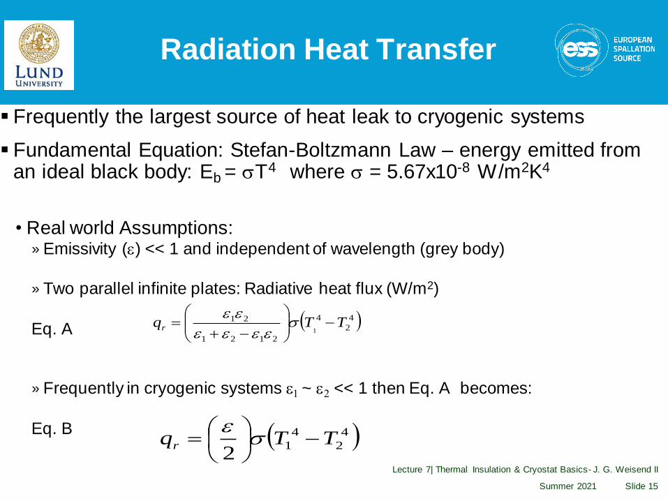
Radiation Heat Transfer
▪ Frequently the largest source of heat leak to cryogenic systems
▪ Fundamental Equation: Stefan-Boltzmann Law – energy emitted from an ideal black body: Eb = sT4 where s = 5.67x10⁻⁸ W/m2K4
• Real world Assumptions:» Emissivity (e) << 1 and independent of wavelength (grey body)
» Two parallel infinite plates: Radiative heat flux (W/m2)
Eq. A
» Frequently in cryogenic systems e1 ~ e2 << 1 then Eq. A becomes:
Eq. B
Summer 2021
Lecture 7| Thermal Insulation & Cryostat Basics- J. G. Weisend II
Slide 15
( )4
2
4
2121
21
1TTqr −
−+= s
eeee
ee
( )4
2
4
12
TTqr −
= s
e
Radiation Heat Transfer
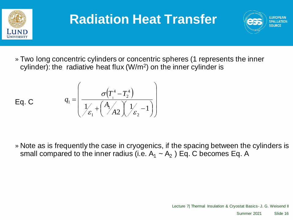
» Two long concentric cylinders or concentric spheres (1 represents the inner cylinder): the radiative heat flux (W/m2) on the inner cylinder is
Eq. C
»Note as is frequently the case in cryogenics, if the spacing between the cylinders is small compared to the inner radius (i.e. A1 ~ A2 ) Eq. C becomes Eq. A
Summer 2021
Lecture 7| Thermal Insulation & Cryostat Basics- J. G. Weisend II
Slide 16
( )
−
+
−=
112
12
1
1
4
2
4
11
ee
s
AA
TTq

Radiation Heat Transfer
▪ Looking at Eq. A, How do we reduce
the radiation heat transfer?
▪ We could reduce the emissivity (e)• This is done in some cases; using either
reflective tape or silver plating• Better below 77 K
• It’s also part of MLI systems (see below)• We have to consider tarnishing
• May be labor intensive
Summer 2021
Lecture 7| Thermal Insulation & Cryostat Basics- J. G. Weisend II
Slide 17
From Helium Cryogenics – S. W. Van Sciver

Radiation Heat Transfer
▪ Another way to reduce radiation heat transfer is to install intermediate actively cooled radiation shields that operate at a temperature between 300 K and the lowest cryogenic temperature. This has several advantages.• It greatly reduces the heat load to the lowest temperature level» Assume parallel plates with e = 0.2
» then from Eq. B q ( 300 K – 4.2 K ) = 46 W/m2 while q (77 – 4.2) = 0.2 W/m2
• It allows heat interception at higher temperatures & thus better Carnot efficiency
• Such an actively cooled shield provides a convenient heat intercept for supports, wires etc to reduce conduction heat leak.
▪ Shields may be cooled by• Liquid baths ( LN2)• Vapor boil off from stored liquid – common in LHe storage dewars
• Cooling flows from refrigeration plants• Conductive cooling via small cryocoolers
Summer 2021
Lecture 7| Thermal Insulation & Cryostat Basics- J. G. Weisend II
Slide 18
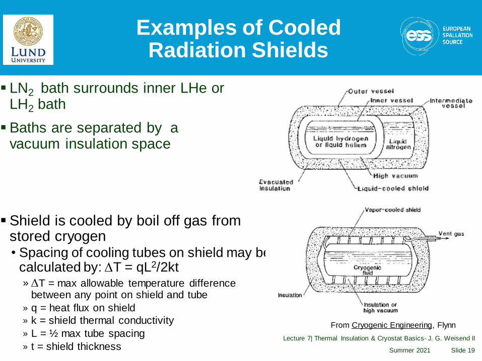
Examples of Cooled Radiation Shields
▪ Shield is cooled by boil off gas from stored cryogen• Spacing of cooling tubes on shield may be
calculated by: DT = qL2/2kt» DT = max allowable temperature difference
between any point on shield and tube
» q = heat flux on shield
» k = shield thermal conductivity
» L = ½ max tube spacing
» t = shield thickness Summer 2021
Lecture 7| Thermal Insulation & Cryostat Basics- J. G. Weisend II
Slide 19
▪ LN2 bath surrounds inner LHe or LH2 bath
▪ Baths are separated by a vacuum insulation space
From Cryogenic Engineering, Flynn

Thermal Radiation Shields
▪ Uncooled thermal radiation shields placed in a vacuum space between the warm & cold surfaces also help reduce the thermal radiation heat leak
▪ It can be shown (with the grey approximation and equal emissivities) that with N shields thermal radiation heat transfer is given by:
Summer 2021
Lecture 7| Thermal Insulation & Cryostat Basics- J. G. Weisend II
Slide 20
( )( )TT LHN
q44
21−
+= s
e
This is the motivation behind Multilayer Insulation

MultiLayer Insulation
▪ Also referred to as superinsulation
▪ Used in the vacuum space of many cryostats (10-5 torr or better for best performance)
▪ Consists of highly reflective thin sheets with poor thermal contact between sheets.• Made of aluminized Mylar ( or less frequently Kapton)
• May include separate non conducting mesh• May use Mylar aluminized on only one side and crinkled to allow only point contacts
between sheets
• Frequently perforated to allow for better pumping
▪ Can be made up into blankets for ease of installation
▪ Don’t pack MLI too tightly. Optimal value is ~ 20 layers / inch
▪ Great care must be taken with seams, penetrations and ends.• Problems with these can dominate the heat leak
Summer 2021
Lecture 7| Thermal Insulation & Cryostat Basics- J. G. Weisend II
Slide 21

MLI
Summer 2021
Lecture 7| Thermal Insulation & Cryostat Basics- J. G. Weisend II
Slide 22

Examples of Proper MLI Installation
Summer 2021
Lecture 7| Thermal Insulation & Cryostat Basics- J. G. Weisend II
Slide 23
From “Cryogenic Engineering” in Wiley Mechanical Engineer’s Handbook

MLI Example from LHC cryostats
Summer 2021
Lecture 7| Thermal Insulation & Cryostat Basics- J. G. Weisend II
Slide 24
“SERIES-PRODUCED HELIUM II CRYOSTATS
FOR THE LHC MAGNETS: TECHNICAL CHOICES,INDUSTRIALISATION, COSTS”A. Poncet and V. Parma
Adv. Cryo. Engr. Vol 53

Porous Insulation
▪ Radiation heat transfer may also be reduced by filling the vacuum space between 300 K and cryogenic temperatures with other materials that are low conductivity and block line of sight
▪ Such materials include:• Glass beads or microspheres
• Perlite powder (made from a volcanic rock)• Opaciated powders – copper or other metallic flakes mixed in with other
powders to further reduce radiant heat transfer• Aerogel
▪ Advantages:• Cheaper
• Easier to install in complex shapes• Better performance than MLI in poor or no vacuum
▪ Frequently used in large storage and transport dewars
Summer 2021
Lecture 7| Thermal Insulation & Cryostat Basics- J. G. Weisend II
Slide 25

Porous Insulation
The total heat transfer through porous insulation between 2 spheres may be estimated by:
▪ Where• t = thickness of Insulation
• = the mean thermal conductivity
• 1 = inner vessel and 2 = outer vessel
▪ Mean thermal conductivities may be found in references such as
Cryogenic Engineering by Flynn
Summer 2021
Lecture 7| Thermal Insulation & Cryostat Basics- J. G. Weisend II
Slide 26
( )21
12 AAt
TTkW
−=
k
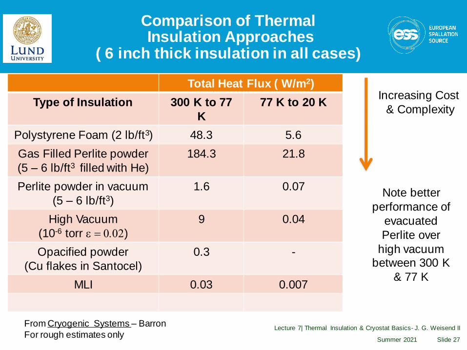
Comparison of ThermalInsulation Approaches
( 6 inch thick insulation in all cases)
Total Heat Flux ( W/m2)
Type of Insulation 300 K to 77
K
77 K to 20 K
Polystyrene Foam (2 lb/ft3) 48.3 5.6
Gas Filled Perlite powder
(5 – 6 lb/ft3 filled with He)
184.3 21.8
Perlite powder in vacuum
(5 – 6 lb/ft3)
1.6 0.07
High Vacuum
(10-6 torr e = 0.02)
9 0.04
Opacified powder
(Cu flakes in Santocel)
0.3 -
MLI 0.03 0.007
Summer 2021
Lecture 7| Thermal Insulation & Cryostat Basics- J. G. Weisend II
Slide 27
Increasing Cost
& Complexity
From Cryogenic Systems – Barron
For rough estimates only
Note better
performance of
evacuated
Perlite over
high vacuum between 300 K
& 77 K
Cryostat Design
▪What is a cryostat?• A device or system for maintaining objects at cryogenic temperatures.
▪ Cryostats which contain superconducting RF systems are traditionally called cryomodules (term originally coined by Jlab)
▪ Cryostats whose principal function is to store cryogenic fluids are frequently called Dewars. Named after the inventor of the vacuum flask and the first person to liquefy hydrogen
Summer 2021
Lecture 7| Thermal Insulation & Cryostat Basics- J. G. Weisend II
Slide 28
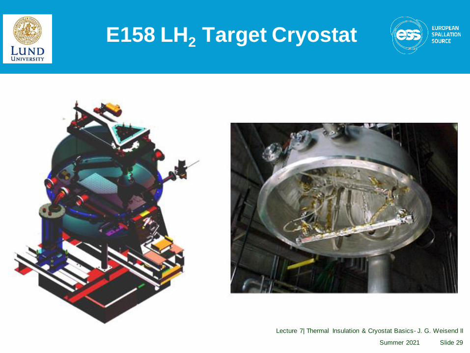
E158 LH2 Target Cryostat
Summer 2021
Lecture 7| Thermal Insulation & Cryostat Basics- J. G. Weisend II
Slide 29

Cryostat Design
▪ Cryostats are one of the technical building blocks of cryogenics
▪ Cryostat design involves many subtopics:• Development of requirements – covered here• Materials selection – already covered
• Thermal insulation - already covered• Support systems – covered here
• Safety – covered in a future lecture• Instrumentation – covered in a future lecture
▪ One of the best ways to learn about cryostat design is through examples (see next talk) Also:• Cryostat Design J.G. Weisend II (Ed) Springer (2016)
▪ There are many different types of cryostats with differing requirements• The basic principles of cryostat design remain the same
• Before we can do anything else we have to define our requirements
Summer 2021
Lecture 7| Thermal Insulation & Cryostat Basics- J. G. Weisend II
Slide 30

Cryostat Requirements
▪Maximum allowable heat leak at various temperature levels• This may be driven by the number of cryostats to be built as well as by the impact of large dynamic heat loads (SCRF or target cryostats)
▪Alignment and vibration requirements• Impact of thermal cycles• Need to adjust alignment when cold or under vacuum?• Alignment tolerances can be quite tight (TESLA : +/- 0.5 mm for cavities and +/- 0.3 mm for SC magnets)
▪Number of feed throughs for power, instrumentation, cryogenic fluid flows, external manipulators
Summer 2021
Lecture 7| Thermal Insulation & Cryostat Basics- J. G. Weisend II
Slide 31

Cryostat Requirements
▪Safety requirements (relief valves/burst discs)• Design safety in from the start. Not as an add on
▪Size and weight • Particularly important in space systems
▪Instrumentation required• Difference between prototype and mass production
▪Ease of access to cryostat components
▪Existing code requirements (e.g. TUV or ASME)
▪Need, if any, for optical windows
▪Presence of ionizing radiation
Summer 2021
Lecture 7| Thermal Insulation & Cryostat Basics- J. G. Weisend II
Slide 32

Cryostat Requirements
▪Expected cryostat life time
▪Will this be a one of a kind device or something to be mass produced?
▪Schedule and Cost• This should be considered from the beginning
All Design is Compromise
Summer 2021
Lecture 7| Thermal Insulation & Cryostat Basics- J. G. Weisend II
Slide 33

Structural Supports
Summer 2021
Lecture 7| Thermal Insulation & Cryostat Basics- J. G. Weisend II
34
▪Solution is highly dependent on cryostat requirements
▪Choose materials carefully• Acceptable for cryogenic temperatures• Low heat leak
▪Don’t over constrain supports: allow for thermal contraction
▪Does solution meet alignment and vibration requirements?
▪Must alignment be changed while cold?

Structural Support Example #1ILC Cryostat
Summer 2021
Lecture 7| Thermal Insulation & Cryostat Basics- J. G. Weisend II
35
• FRP support between 300 K and Cryo temps
• Cavity assemblies tied to 300 mm pipe backbone
• All other connections to 300 K have flex line or bellowsin line
• Meets alignment specs
2.2 K forward
4.5 K forward
40 K forward
2 K 2-phase
cavity
2 K return
80 K return
4.5 K return
cool down/
warmup
support
coupler
300 mm
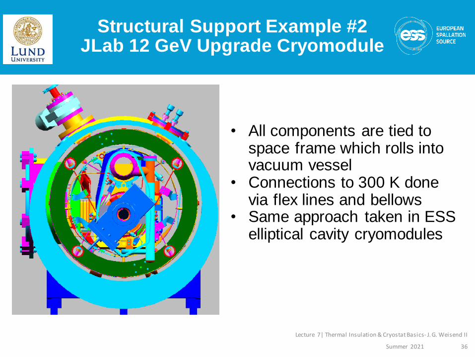
Structural Support Example #2JLab 12 GeV Upgrade Cryomodule
Summer 2021
Lecture 7| Thermal Insulation & Cryostat Basics- J. G. Weisend II
36
• All components are tied to space frame which rolls intovacuum vessel
• Connections to 300 K donevia flex lines and bellows
• Same approach taken in ESS elliptical cavity cryomodules
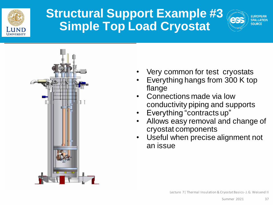
Structural Support Example #3Simple Top Load Cryostat
Summer 2021
Lecture 7| Thermal Insulation & Cryostat Basics- J. G. Weisend II
37
• Very common for test cryostats• Everything hangs from 300 K top
flange• Connections made via low
conductivity piping and supports• Everything “contracts up”• Allows easy removal and change of
cryostat components• Useful when precise alignment not
an issue

Tips for Successful Cryostat Design
1. Define and prioritize requirements first. Optimize the cryostat design based on these priorities.
2. Design in safety features from the start of the project.
3. Only use materials shown to be appropriate for cryogenic temperatures.
4. Review literature & learn from previous efforts. Take advantage of existing codes and standards if possible.
5. Use tested commercial solutions whenever possible.
6. Intercept heat at higher intermediate temperatures.
7. Allow for the effect of thermal contraction on cryostat alignment and design. Do not over constrain the movement of cryostat components as they cool.
8. Avoid feed throughs & demountable seals at cryogenic temperatures.
9. Be sure to properly heat sink temperature sensor wires to ensure reduced heat leak and an accurate reading.
38

Tips for Successful Cryostat Design
10.Install sensors such a pressure transducers and flow meters at room temperature when possible.
11.Analyze the design for possible thermoacoustic oscillations
12.Conduct design reviews. These should include experts not directly involved in the design under review. Ideally, there should be at least reviews at the preliminary or conceptual level and again once the detailed design is complete. Safety should be a part of these reviews or separate safety reviews should be held.
13.Conduct prototype tests when required. Leave enough time in the design process to benefit from the results of such tests.
14.In cases where a large number of cryostats are to be produced, carry out series testing of the production cryostats in addition to any prototype testing. Allow sufficient resources (time, facilities, funding) in the project plan to accomplish these tests.
39