
Lecture 6 Three Phase Induction Motors - Cairo...
20
Lecture 6 Three Phase Induction Motors Dr. Mostafa Elshahed Objectives • Learn a brief history of the electrical power systems construction. • Differentiate between the various types of generating electric power stations. • List and describe the more commonly used equipment in an electric substation. • Understand and define the different elements of a protection system. • Learn the principle of power factor improvement and evaluating the cost of electricity. • Define the equivalent circuit of the transformer and calculate its efficiency and voltage regulation. • Derive the induced voltage and torque in DC & A.C. machines and determine their equivalent circuit. • Determine the power flow diagram and the efficiency DC & A.C. machines. • Differentiate between the various types of Power Electronics Rectifiers
Transcript of Lecture 6 Three Phase Induction Motors - Cairo...

Lecture 6Three Phase Induction Motors
Dr. Mostafa Elshahed
Objectives
• Learn a brief history of the electrical power systems construction.
• Differentiate between the various types of generating electric power stations.
• List and describe the more commonly used equipment in an electric substation.
• Understand and define the different elements of a protection system.
• Learn the principle of power factor improvement and evaluating the cost of
electricity.
• Define the equivalent circuit of the transformer and calculate its efficiency and
voltage regulation.
• Derive the induced voltage and torque in DC & A.C. machines and determine their
equivalent circuit.
• Determine the power flow diagram and the efficiency DC & A.C. machines.
• Differentiate between the various types of Power Electronics Rectifiers

Housing
Motor
•Large three-phase induction motor•Stator of a large induction motor
Different Types of Electrical Motors

INTRODUCTION
• The three-phase induction motor is the extensively used for various
kinds of industrial drives.
• AC induction motors are also the most common motors used in
main powered home appliances.
Advantages of 3 phase induction motor
• Generally easy to build and cheaper than corresponding dc or
synchronous motors
• Induction motor is robust
• The motor is driven by the rotational magnetic field produced by 3
phase currents, hence no commutator or blush is required
• Maintenance is relatively easy and at low cost
• Satisfactory efficiency and reasonable power factor
• A manageable torque-speed curve
• Stable operation under load
• Range in size from few Watts to several MW

Disadvantages of 3 phase induction motor
• Induction motor has low inherent starting torque
• Draw large starting currents, typically 6-8 x their full load values
• Speeds not easily controlled as DC motors
• Operate with a poor lagging power factor when lightly loaded
Induction Motor Components
An induction motor has two main parts:
• A stator – consisting of a steel frame that supports a hollow, cylindrical core
of stacked laminations. Slots on the internal circumference of the stator
house the stator winding.
• A rotor – also composed of punched laminations, with rotor slots for the
rotor winding.
•The rotor is separated from the stator by a small air-gap which ranges
from 0.4 mm to 4 mm, depending on the power and the size of the
motor.

•Induction Motor: Stator Winding
• Spreading the coil in this manner creates a sinusoidal flux distribution per pole,
which improves performance and makes the motor less noisy (sound and
electrically).
Types of ac induction motor rotors
There are two-types of rotor windings:
Squirrel-cage windings, which produce a
squirrel-cage induction motor (most common)
Almost 90% of the three-phase AC
Induction motors are of this type.
Conventional 3-phase windings made of
insulated wire, which produce a wound-rotor
induction motor (special characteristics)

Winding/Rotor Arrangements for3 Phase Induction Machine
Three Phase Slip Ring Induction Motor
• A wound rotor or slip ring motor has a 3-phase winding, similar to
the stator winding. The rotor winding terminals are connected to
three slip rings which turn with the rotor. The slip rings/brushes
allow external resistors to be connected in series with the winding.
ThreePhaseSupply
Brush
Rotor Windings Slip RingsStator Windings
Running Position
Starting PositionExternal Resistors
•Expensive to manufacture and it is vulnerable to overheat
•but we can control the starting torque and running characteristics

•Squirrel Cage Rotor
Induced Voltage Generation
Faraday’s law
• Voltage is induced in a
conductor that moves
perpendicular to a
magnetic field,
• The induced voltage is:
E= Blv
Magnetic field B into page
Conductormoving
upward withspeed v
Induced voltage V
Conductor length L
v v
•Voltage induced in a
conductor moving through a
magnetic field.

Motor Force Generation
• The interaction between the magnetic field B and the current generates a force
F = B L I+
B B B B
F
B
•Force direction on a current-carrying conductor placed in a magnetic field (B) (current into the page).
Rotating Field Concept
• Before discussing the theory of operation for the induction motor a
very basic concept, that of a rotating field, must be understood.
• A rotating and constant resultant magnetic field rotating at a
constant speed may be produced by any three-phase group of
windings displaced in space if the currents flowing through the
windings are also displaced in time.

Instantaneous Values of three phase Voltages
VoltageField

Operation Principle
• The three fluxes generated by the phase windings are separated by 120° in space and in time for a two-pole motor
• The total flux in the machine is the sum of the three fluxes.
• The summation of the three ac fluxes results in a rotating flux, which turns with constant speed and has constant amplitude.
• The rotating flux induces a voltage in the short-circuited bars of the rotor. This voltage drives current through the bars.
• The interaction of the rotating flux and the rotor current generates a force that drives the motor.
• The force is proportional with the flux density and the rotor bar current
• The voltage and current generation in the rotor bar require a speed difference between the rotating field and the rotor.
• Consequently, the rotor speed is always less than the magnetic field speed.

• The speed of the rotating field:
• Rotor Speed:
• Slip Speed:
• Slip:
• The frequency in the rotor:
fR = frequency of rotor voltage and
current
P
fns
120
mn
ms nn
s
ms
n
nns
sff R
For an induction motor with P poles and f frequency,
•Slip
• For induction motors a very important parameter is the slip of the
motor The slip, s, defines the relative speed difference between
synchronous speed and rotor speed and is given by:
• where ω is expressed in rads/s and n is expressed in rpm.
• At no-load, the slip is nearly zero (<0.1%).
• At full load, the slip for large motors rarely exceeds 0.5%. For small
motors at full load, it rarely exceeds 5%.
• The slip is 100% for locked rotor (Starting).
s
ms
s
ms
n
nns

Induction Motor–Rotating Field: Direction of rotation
• The phase current waveforms follow
each other in the sequence A-B-C.
This produces a clockwise rotating
magnetic field.
• If we interchange any two of the lines
connected to the stator, the new phase
sequence will be A-C-B. This will
produce a counterclockwise rotating
field, reversing the motor direction.
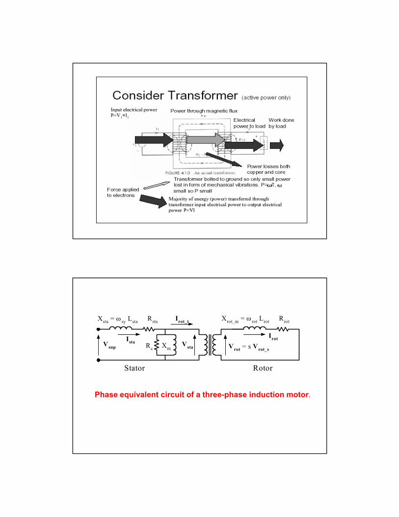
Stator Rotor
Xrot_m
= rot
Lrot
Rrot
Irot
Vrot = s Vrot_s
Rsta
Irot_t
VstaVsup
IstaXmRc
Xsta = sy Lsta
Phase equivalent circuit of a three-phase induction motor.

Torque versus speed
Fan
Conveyer
Torque versus slip
s
ms
n
nns

Power Flow Diagram
Power and Losses Chart of an induction motor
AIR
GAP
Stator Copperloss Pcu1
Statorinputpower
Pin
Powertransferred
to rotor
Rotorinputpower
Core loss(Hysteresis andeddy current)
Pc1
Rotor Copper LossPcu2
MechanicalLosses (Fricton& Windage)
Pmech
Net (usable)Mechanical
Power outputPout
GrossMechanical
PoweroutputPgross

• The supply power is:
cos3nP LL IVi • The motor efficiency:
• Motor torque:
• Rotor cu losses, gap power and developed power:
in
out
P
P
dev
devout
out
PT
PT
GapCuGapDevGapCu PsPPPsPP 1 22
Example

Example

Selected Problems
3 A three phase, four- pole, 30-hp, 220-V, 60-Hz, Y-connected
induction motor draws a current of 77 A from the line source at a
power factor of 0.88. At this operating condition, the motor losses
are known to be the following:
Stator copper losses = 1033 W Stator core losses = 485 W
Rotor copper losses = 1299 W Rotational losses = 540 W
Determine the power transferred across the air gap, the internally
developed torque, the slip, the horsepower output, the motor speed
in rpm, the torque corresponding to the rotational losses, and the
efficiency of operation at the stated condition.
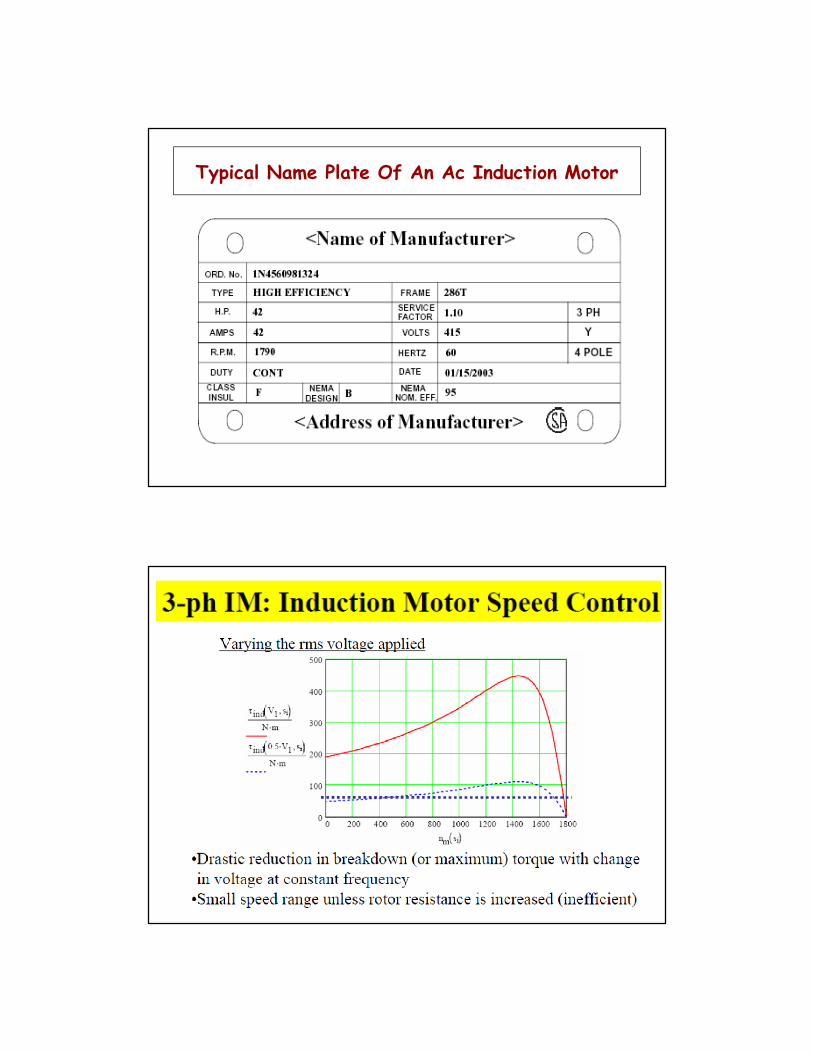
Typical Name Plate Of An Ac Induction Motor
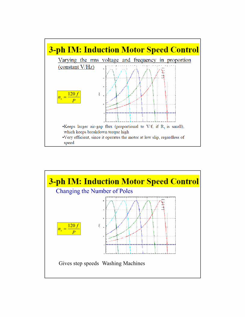
P
fns
120
P
fns
120
Gives step speeds Washing Machines


