Lecture 5 Substation Automation Systems - Royal …€¦ · · 2016-09-15Lecture 5 Substation...
25
1 1 Lecture 5 Substation Automation Systems 2 Course map
Transcript of Lecture 5 Substation Automation Systems - Royal …€¦ · · 2016-09-15Lecture 5 Substation...

1
1
Lecture 5 Substation Automation Systems
2
Course map
2
3
Contents of the Lecture
• Part 1 – Substation Automation – Components – Substation Automation Functions – Communication within the Substation (Intro)
• Part 2 – Architectures….. – Smartgrids Architecture Reference Model
4
Part 1 Components & Architectures
3
5
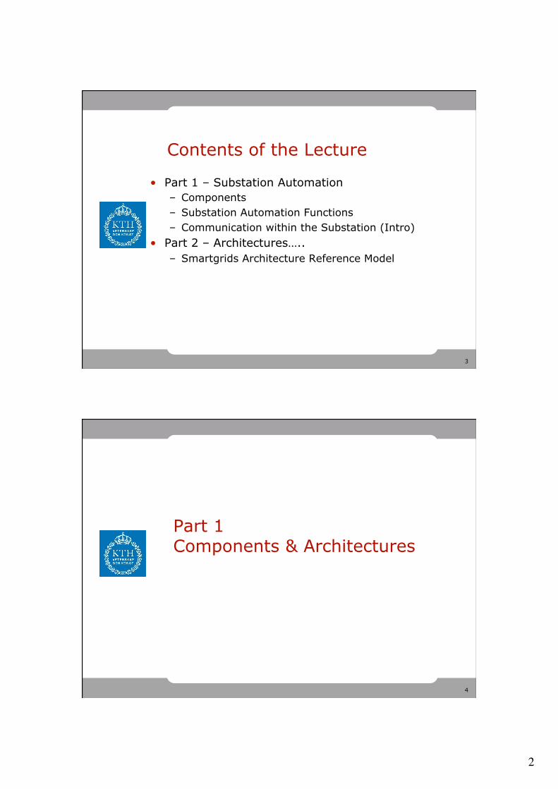
Process Interface
6
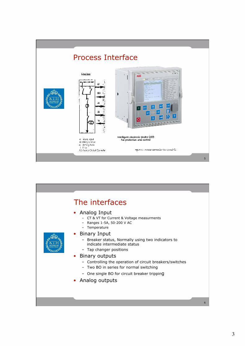
The interfaces • Analog Input
– CT & VT for Current & Voltage measurments – Ranges 1-5A, 50-200 V AC – Temperature
• Binary Input – Breaker status, Normally using two indicators to
indicate intermediate status – Tap changer positions
• Binary outputs – Controlling the operation of circuit breakers/switches – Two BO in series for normal switching
– One single BO for circuit breaker tripping • Analog outputs
4
7
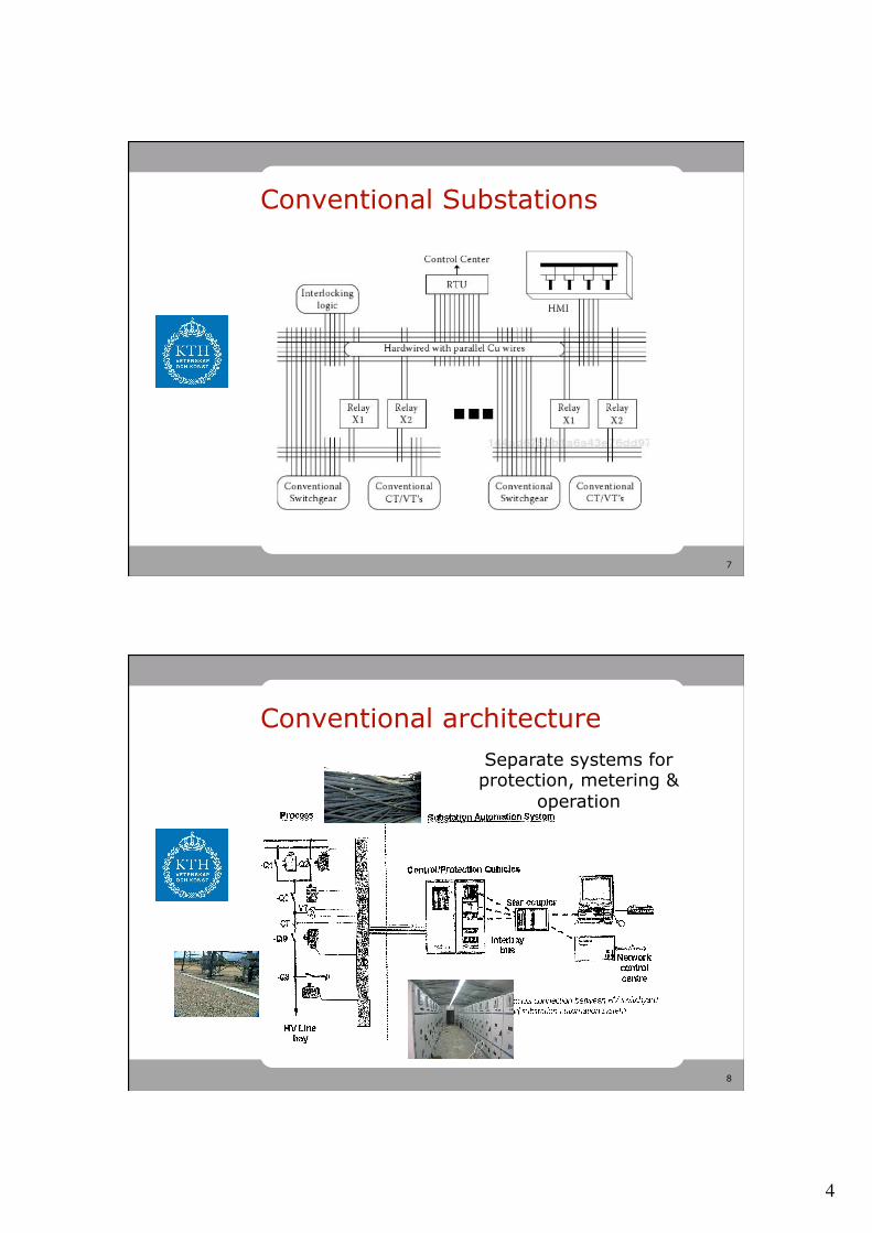
Conventional Substations
8
Conventional architecture Separate systems for protection, metering &
operation
5
9
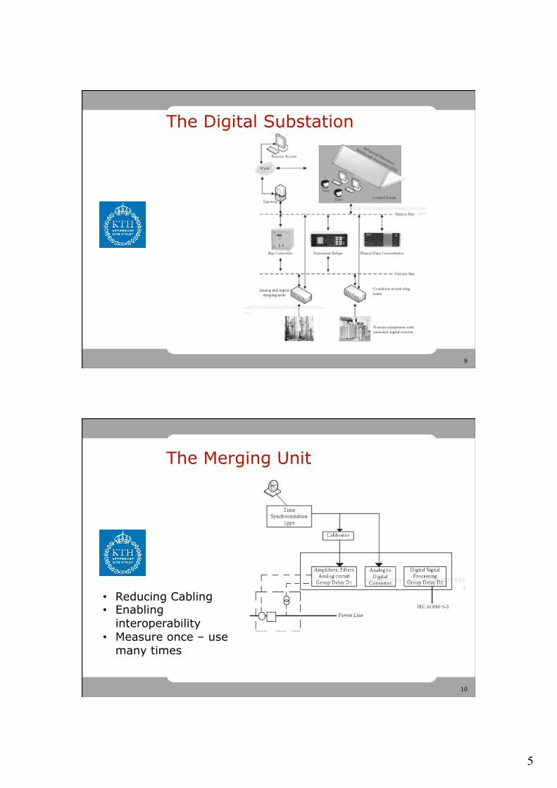
The Digital Substation
10
The Merging Unit
• Reducing Cabling • Enabling
interoperability • Measure once – use
many times
6
11
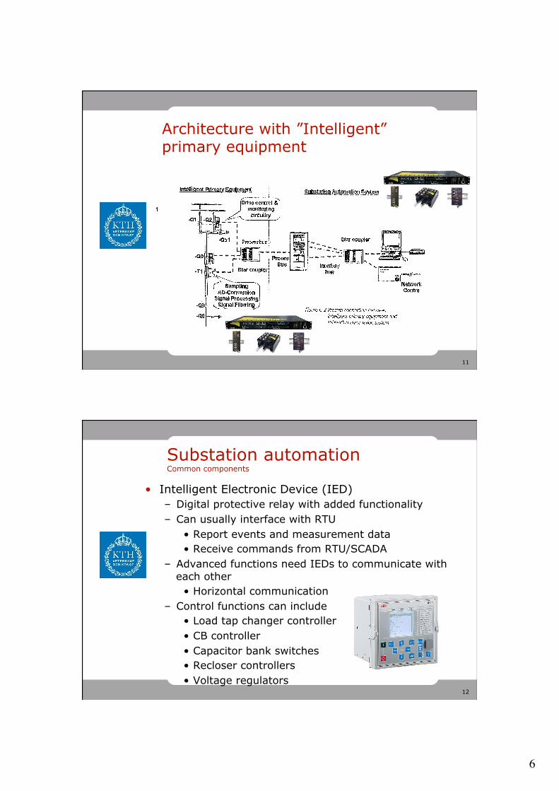
Architecture with ”Intelligent” primary equipment
12
Substation automation Common components
• Intelligent Electronic Device (IED) – Digital protective relay with added functionality – Can usually interface with RTU
• Report events and measurement data • Receive commands from RTU/SCADA
– Advanced functions need IEDs to communicate with each other
• Horizontal communication – Control functions can include
• Load tap changer controller • CB controller • Capacitor bank switches • Recloser controllers • Voltage regulators
7
13
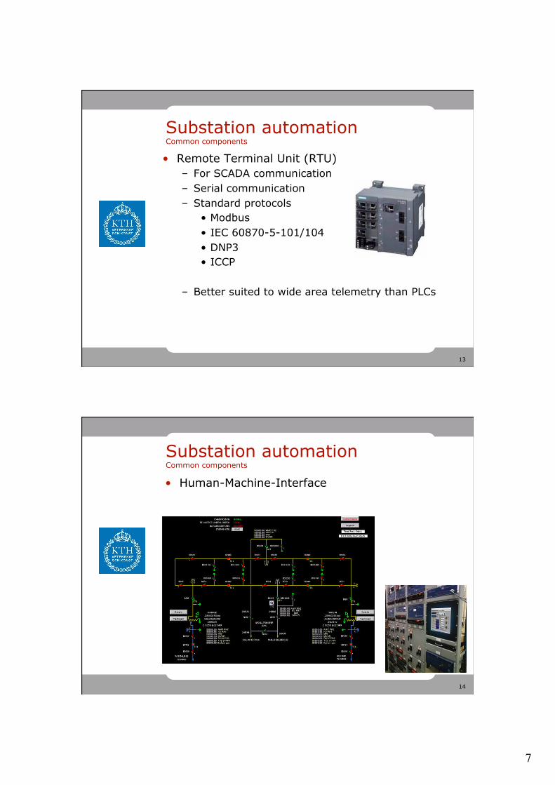
Substation automation Common components
• Remote Terminal Unit (RTU) – For SCADA communication – Serial communication – Standard protocols
• Modbus • IEC 60870-5-101/104 • DNP3 • ICCP
– Better suited to wide area telemetry than PLCs
14
Substation automation Common components
• Human-Machine-Interface
8
15
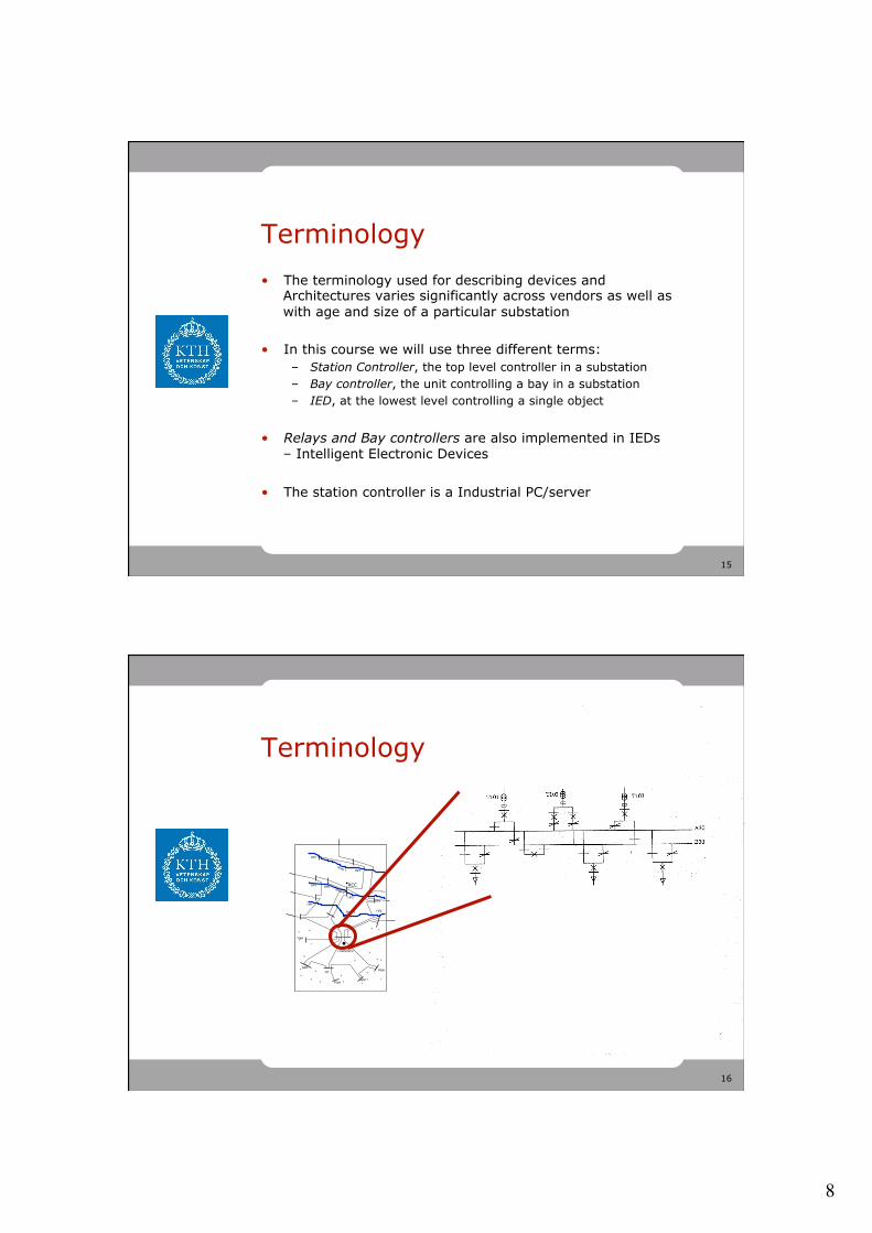
Terminology • The terminology used for describing devices and
Architectures varies significantly across vendors as well as with age and size of a particular substation
• In this course we will use three different terms: – Station Controller, the top level controller in a substation – Bay controller, the unit controlling a bay in a substation – IED, at the lowest level controlling a single object
• Relays and Bay controllers are also implemented in IEDs – Intelligent Electronic Devices
• The station controller is a Industrial PC/server
16
River 1
River 2
River 3
HP1
HP2
HP1 HP2
HP3HP4
HP1
HP2
•TOWN/NCC
++
+
+
+
+
+
+P&H
+
+
++
++
+
+
++
+
++
++
+
+
GTNPP
P&H
NPPP&H
RCC•
River 1
River 2
River 3
HP1
HP2
HP1 HP2
HP3HP4
HP1
HP2
•TOWN/NCC
++
+
+
+
+
+
+P&H
+
+
++
++
+
+
++
+
++
++
+
+
GTNPP
P&H
NPPP&H
RCC•
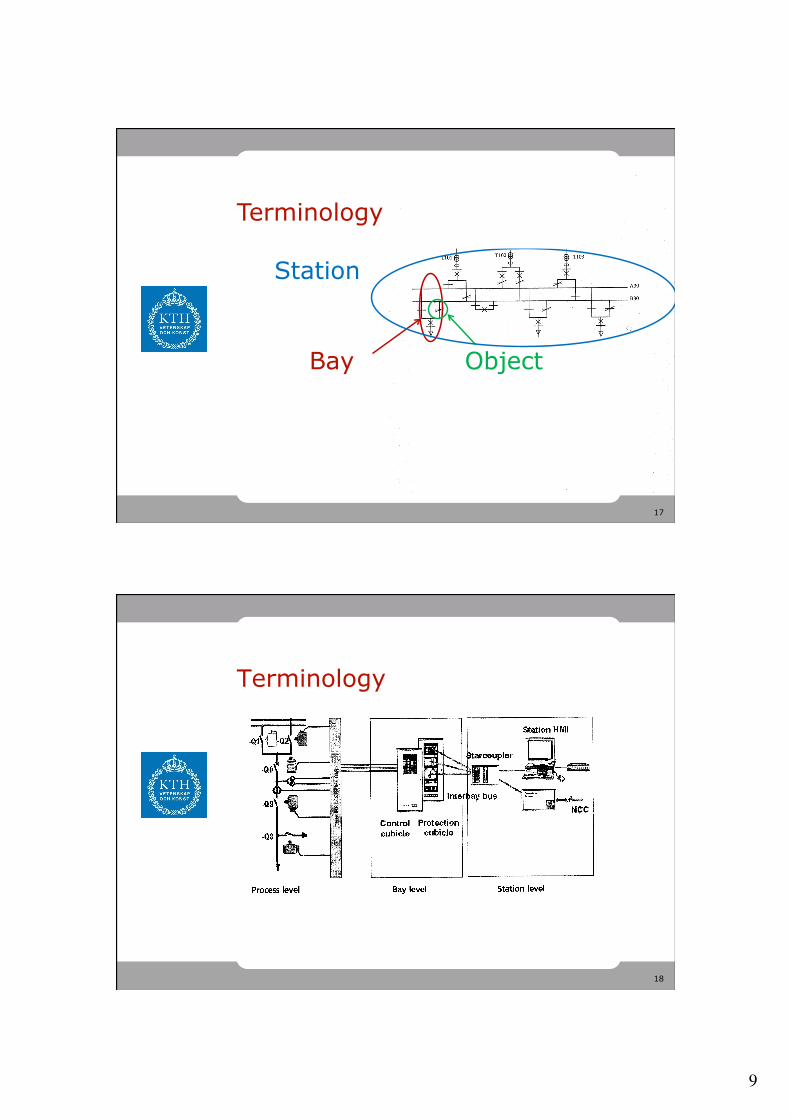
Terminology
9
17
Bay Object
Station
Terminology
18
Terminology
10
19
Part 1 Substation Automation Functions
20
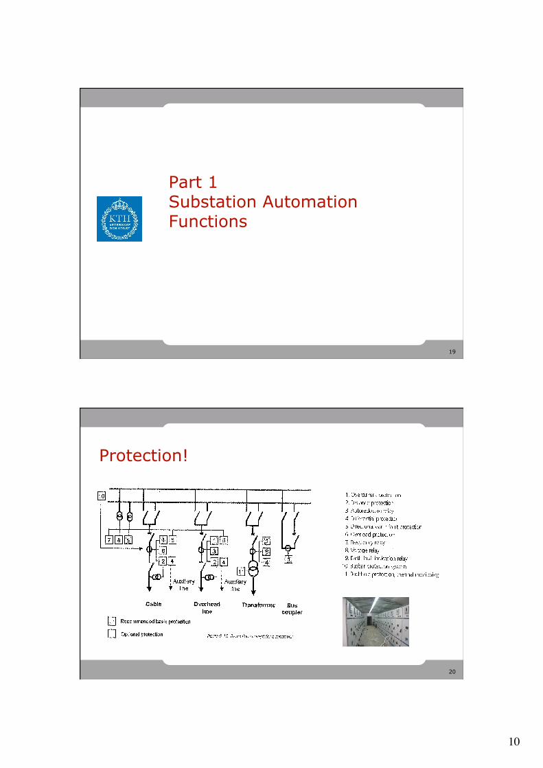
Protection!

11
21
Interlocking
• To ensure that operation of Switchgear is safe and in accordance with standards
• For instance preventing of moving of a disconnector carrying load
• Implemented as functions in a bay Controller that controls the switchgear in the bay.
22
Switching Sequences
• To ensure that switching operations are performed in a correct sequence, and to automate manual work
• For example, transfering a feeder from one busbar to another, or restoration after a fault
• Implemented in station or bay controller depending on scope of the sequence
See e.g. 4.9.2.1 & 4.9.2.2
12
23
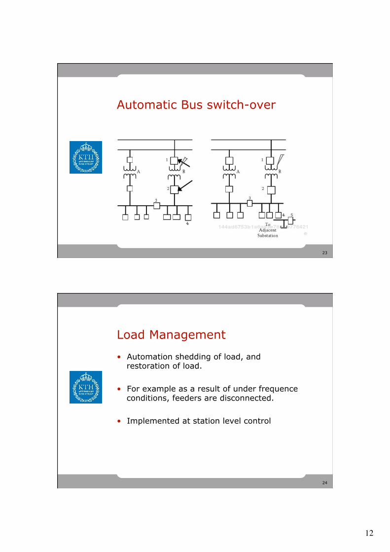
Automatic Bus switch-over
24
Load Management
• Automation shedding of load, and restoration of load.
• For example as a result of under frequence conditions, feeders are disconnected.
• Implemented at station level control
13
25
Communication in the Substation (Intro)
26
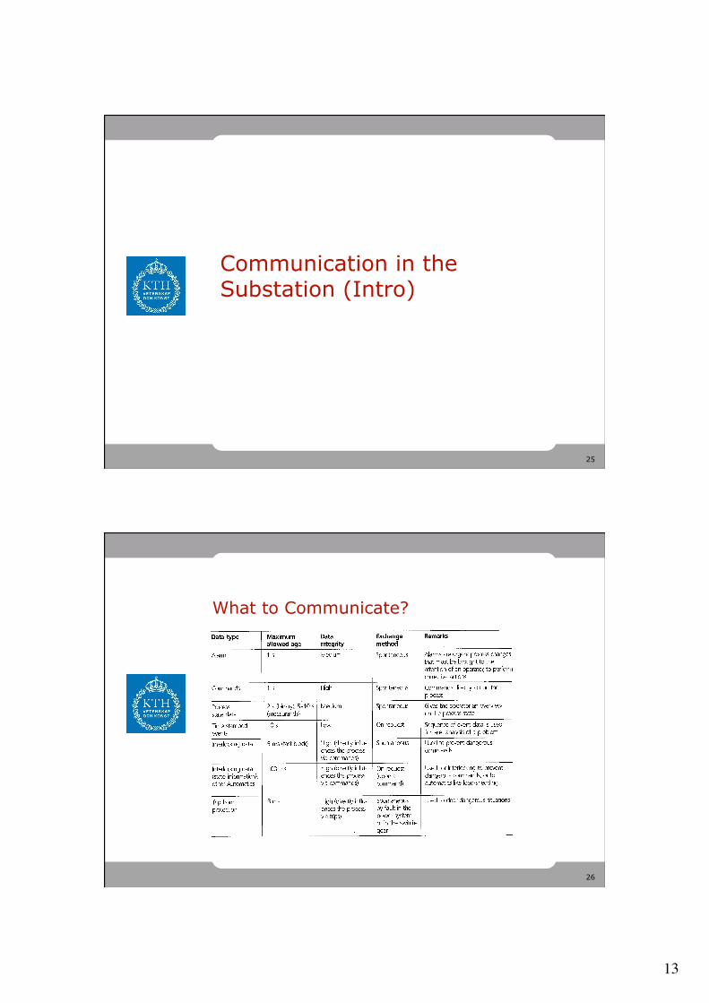
What to Communicate?
14
27
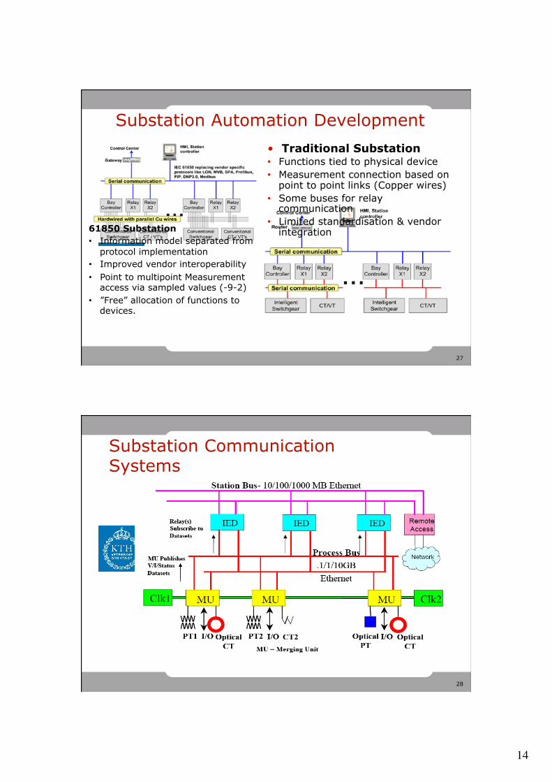
Substation Automation Development
Images from Industrial Ethernet Book, Christoph Brunner, www.iebmedia.com
• Traditional Substation • Functions tied to physical device • Measurement connection based on
point to point links (Copper wires) • Some buses for relay
communication • Limited standardisation & vendor
integration 61850 Substation • Information model separated from
protocol implementation • Improved vendor interoperability • Point to multipoint Measurement
access via sampled values (-9-2) • ”Free” allocation of functions to
devices.
28
Substation Communication Systems

15
29
Smartgrids Architecture Reference Model
30
There are lots of ways to describe systems
16
31
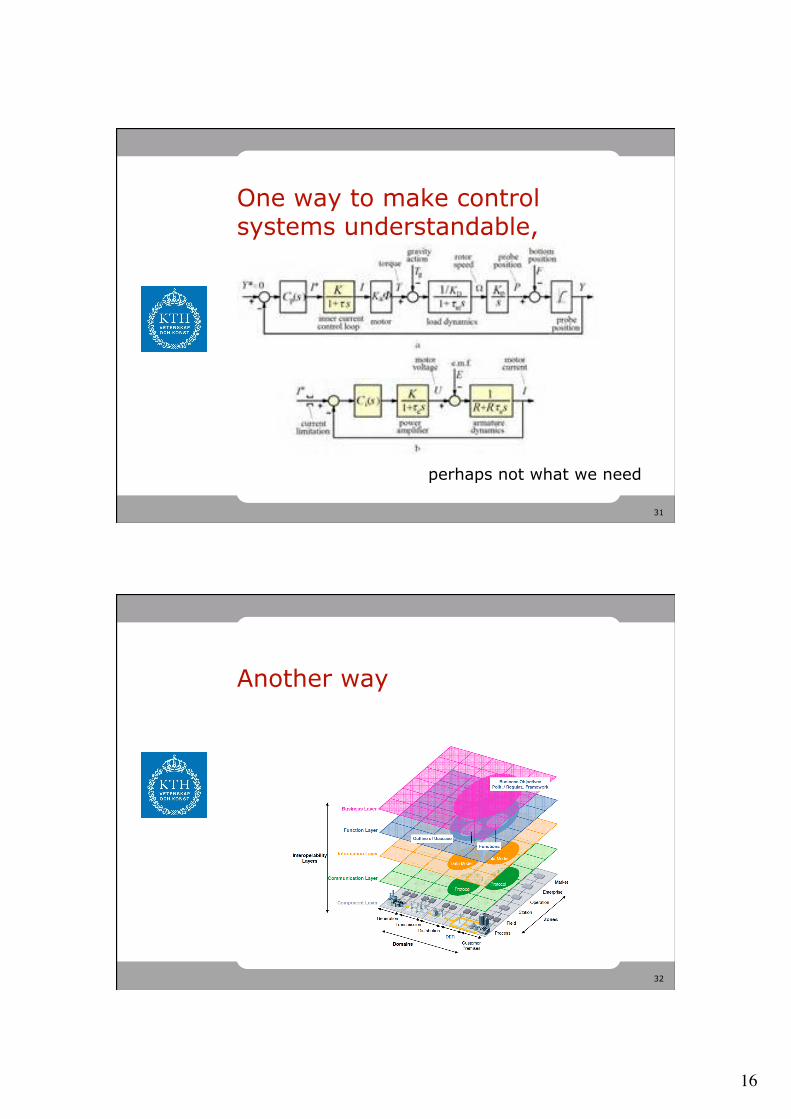
One way to make control systems understandable,
perhaps not what we need
32
Another way
17
33
Some background first
• The EC has issued a mandate (M/490) for the standardization of Smart grid functionalities to CEN, CENELEC and ETSI.
• The expected framework will consist of the following deliverables: – A technical reference architecture, which will represent the
functional information data flows between the main domains and integrate many systems and subsystems architectures.
– A set of consistent standards, which will support the information exchange (communication protocols and data models) and the integration of all users into the electric system operation.
– Sustainable standardization processes and collaborative tools to enable stakeholder interactions, to improve the two above and adapt them to new requirements based on gap analysis, while ensuring the fit to high level system constraints such as interoperability, security, and privacy, etc.
34
What is a reference architecture?
In short: it is the specification of which language you should use to describe the
system you are describing.

18
35
Example: Reference architecture for for Power systems
A set of symbols
We need this for communication & control systems
One-line diagram
Rules on how you can combine them
Avoiding this…
36
The context– the Smartgrid Plane
19
37
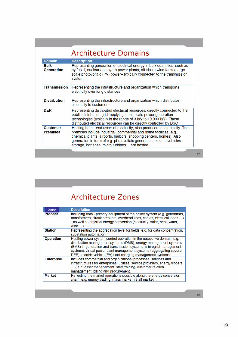
Architecture Domains
38
Architecture Zones Zone
20
39
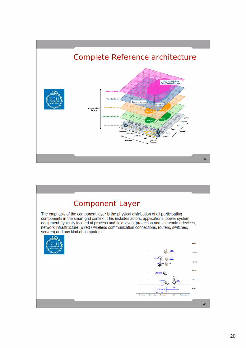
Complete Reference architecture
40
Component Layer

21
41
42
Function layer
22
43
44
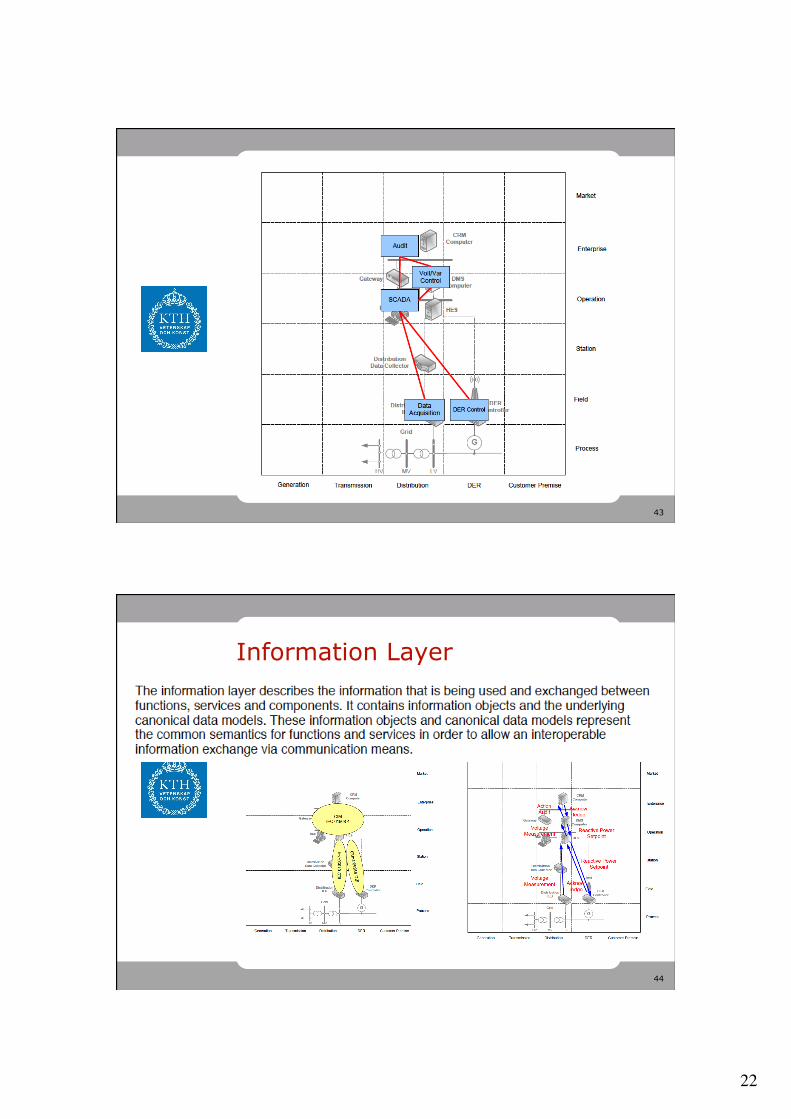
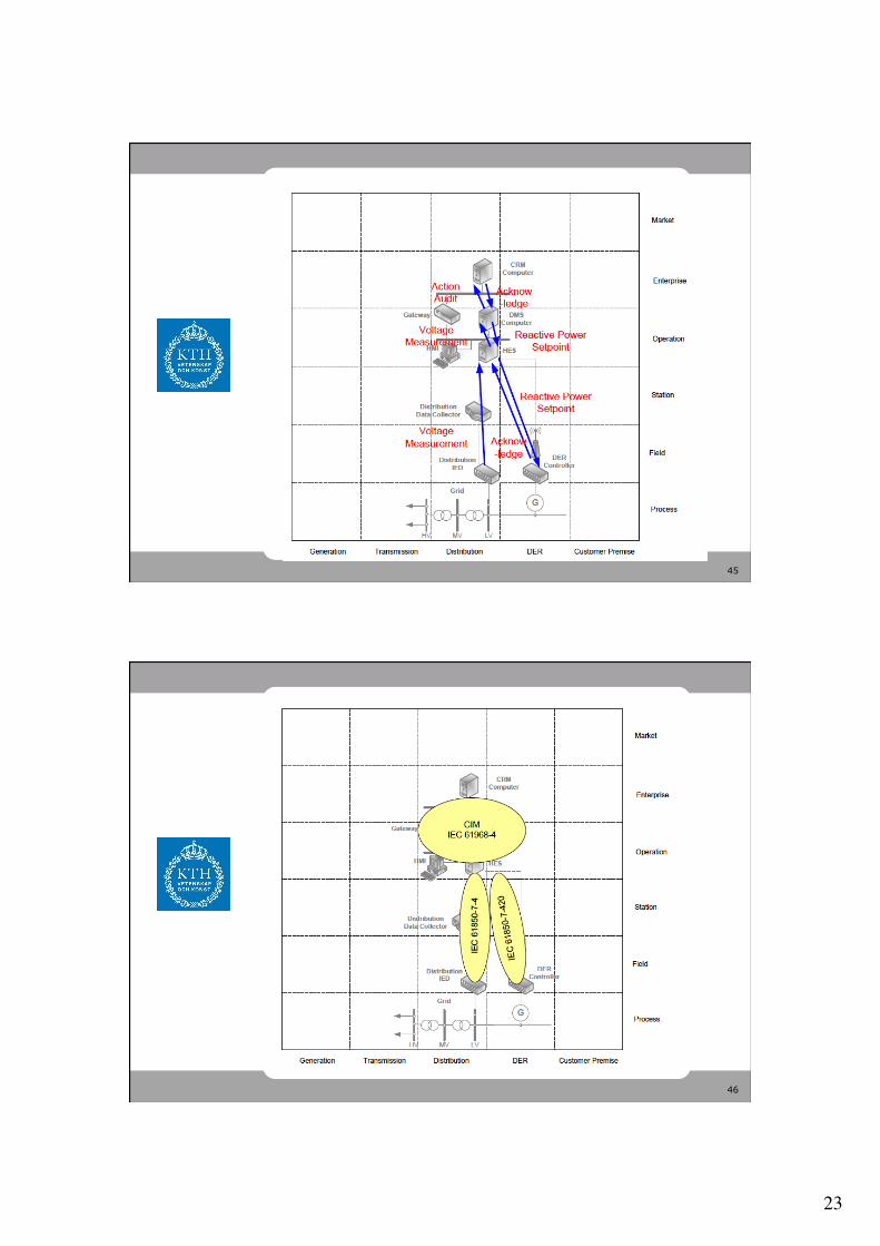
Information Layer
23
45
46
24
47
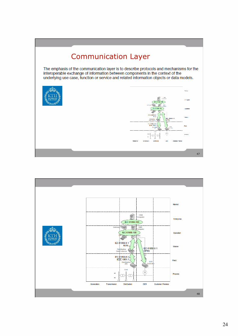
Communication Layer
48
25
49
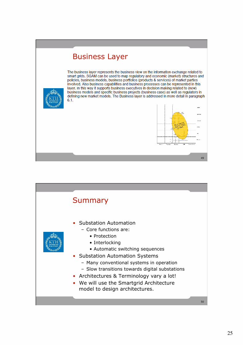
Business Layer
50
Summary
• Substation Automation – Core functions are:
• Protection • Interlocking • Automatic switching sequences
• Substation Automation Systems – Many conventional systems in operation – Slow transitions towards digital substations
• Architectures & Terminology vary a lot! • We will use the Smartgrid Architecture
model to design architectures.