Lecture 5: SPICE - Saraju Mohanty · Noise Analysis • The noise analysis portion of SPICE does...
76
CSCE 6933/5933 Advanced Topics in VLSI Systems Instructor: Saraju P. Mohanty, Ph. D. Advanced Topics in VLSI Systems 1 Lecture 5: SPICE NOTE: The figures, text etc included in slides are borrowed from various books, websites, authors pages, and other sources for academic purpose only. The instructor does not claim any originality.
Transcript of Lecture 5: SPICE - Saraju Mohanty · Noise Analysis • The noise analysis portion of SPICE does...
CSCE 6933/5933 Advanced Topics in VLSI Systems
Instructor: Saraju P. Mohanty, Ph. D.
Advanced Topics in VLSI Systems
1
Lecture 5: SPICE
NOTE: The figures, text etc included in slides are borrowed from various books, websites, authors pages, and other sources for academic purpose only. The instructor does not claim any originality.
Lecture Outlines • About SPICE • Supported analysis by SPICE • Circuit Simulation • Methods for solving linear and non linear
equations
Advanced Topics in VLSI Systems
2
About SPICE • SPICE –Simulation Program with Integrated Circuit
Emphasis • SPICE is a general-purpose circuit simulation program for
nonlinear dc, nonlinear transient, and linear ac analyses • Circuits may contain:
– resistors, capacitors, inductors, mutual inductors, independent voltage and current sources
– four types of dependent sources – lossless and lossy transmission lines (two separate
implementations), switches, uniform distributed RC lines – common semiconductor devices: diode, BJT, FET
Advanced Topics in VLSI Systems
3
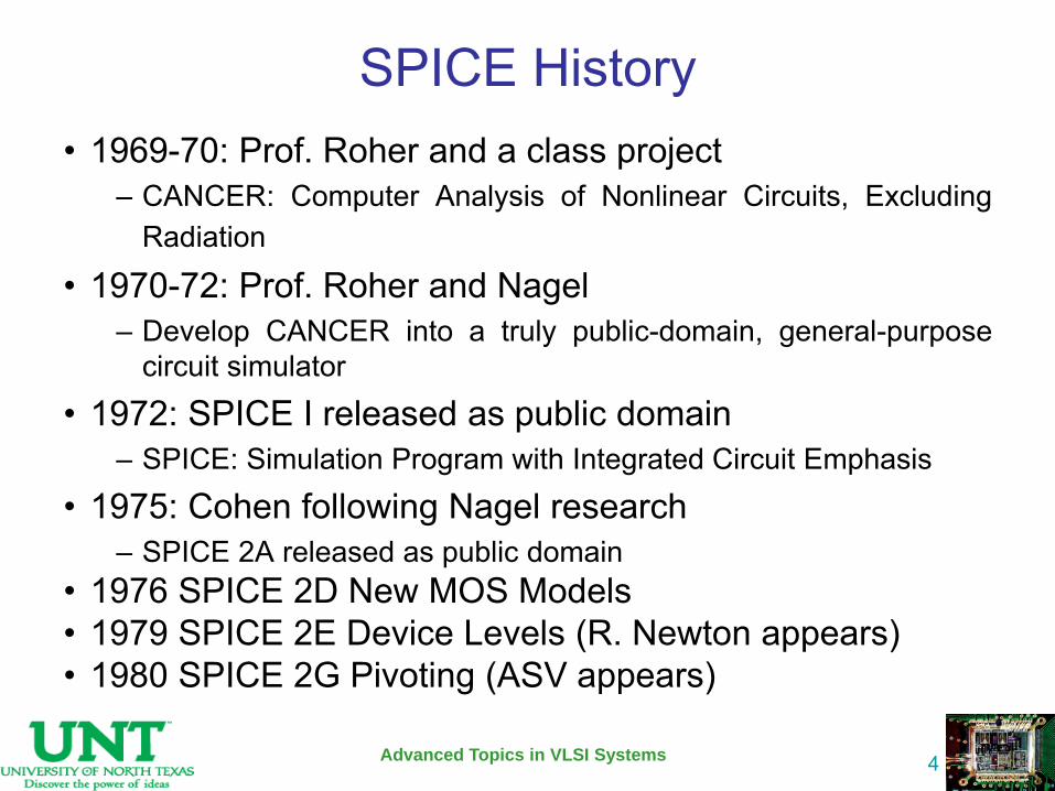
SPICE History • 1969-70: Prof. Roher and a class project
– CANCER: Computer Analysis of Nonlinear Circuits, Excluding Radiation
• 1970-72: Prof. Roher and Nagel – Develop CANCER into a truly public-domain, general-purpose
circuit simulator
• 1972: SPICE I released as public domain – SPICE: Simulation Program with Integrated Circuit Emphasis
• 1975: Cohen following Nagel research – SPICE 2A released as public domain
• 1976 SPICE 2D New MOS Models • 1979 SPICE 2E Device Levels (R. Newton appears) • 1980 SPICE 2G Pivoting (ASV appears)
Advanced Topics in VLSI Systems
4
SPICE History …
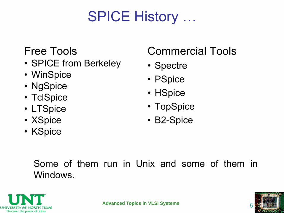
Free Tools • SPICE from Berkeley • WinSpice • NgSpice • TclSpice • LTSpice • XSpice • KSpice
Commercial Tools • Spectre • PSpice • HSpice • TopSpice • B2-Spice
Advanced Topics in VLSI Systems
5
Some of them run in Unix and some of them in Windows.
SPICE History …
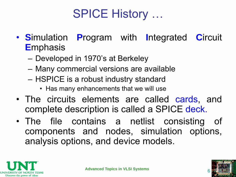
• Simulation Program with Integrated Circuit Emphasis – Developed in 1970’s at Berkeley – Many commercial versions are available – HSPICE is a robust industry standard
• Has many enhancements that we will use
• The circuits elements are called cards, and complete description is called a SPICE deck.
• The file contains a netlist consisting of components and nodes, simulation options, analysis options, and device models.
Advanced Topics in VLSI Systems
6

Writing Spice Decks • Writing a SPICE deck is like writing a good
program – Plan: sketch schematic on paper or in editor
• Modify existing decks whenever possible
– Code: strive for clarity • Start with name, email, date, purpose • Generously comment
– Test: • Predict what results should be • Compare with actual • Garbage In, Garbage Out!
Advanced Topics in VLSI Systems
7

SPICE Sources
• DC Source Vdd vdd gnd 2.5
• Piecewise Linear Source Vin in gnd pwl 0ps 0 100ps 0 150ps 1.8 800ps 1.8
• Pulsed Source Vck clk gnd PULSE 0 1.8 0ps 100ps 100ps 300ps 800ps
Advanced Topics in VLSI Systems
8
PULSE v1 v2 td tr tf pw per
v1
v2
td tr tfpw
per
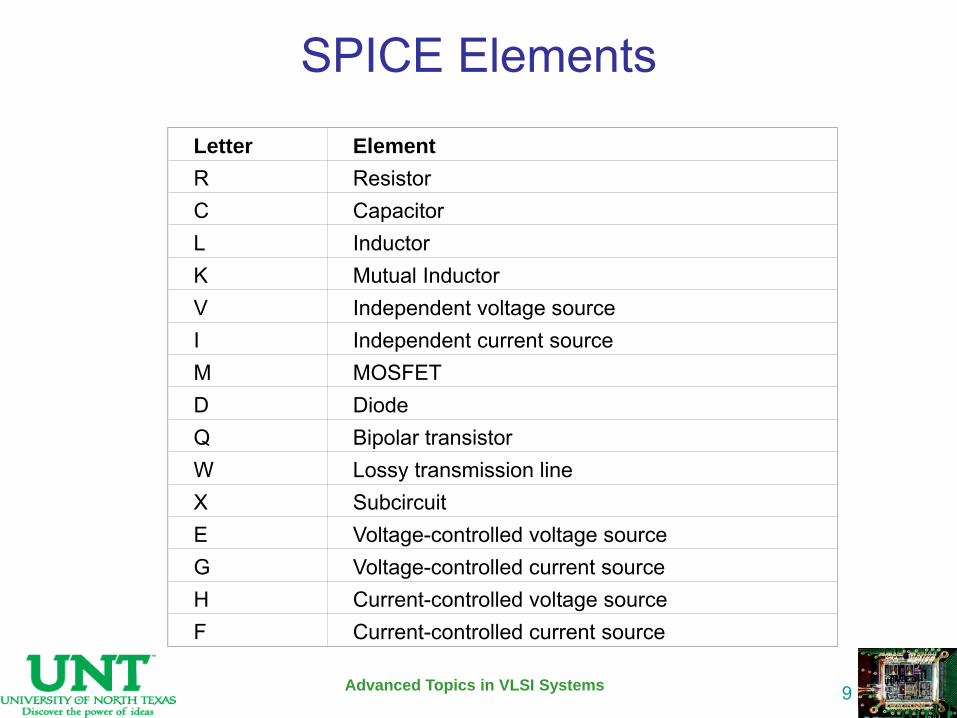
SPICE Elements
Advanced Topics in VLSI Systems
9
Letter
Element R
Resistor C
Capacitor L
Inductor K
Mutual Inductor V
Independent voltage source I
Independent current source M
MOSFET D
Diode Q
Bipolar transistor W
Lossy transmission line X
Subcircuit E
Voltage-controlled voltage source G
Voltage-controlled current source H
Current-controlled voltage source F
Current-controlled current source
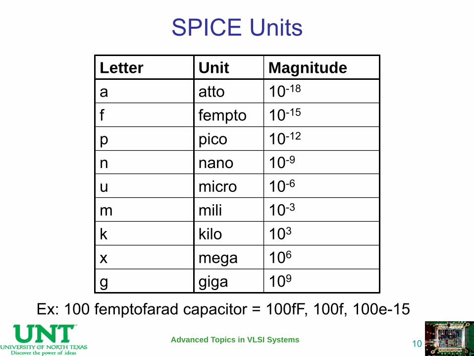
SPICE Units
Advanced Topics in VLSI Systems
10
Letter Unit Magnitude
a atto 10-18
f fempto 10-15
p pico 10-12
n nano 10-9
u micro 10-6
m mili 10-3
k kilo 103
x mega 106
g giga 109
Ex: 100 femptofarad capacitor = 100fF, 100f, 100e-15
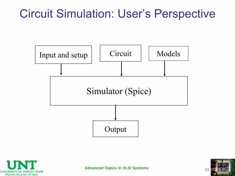
Circuit Simulation: User’s Perspective
Advanced Topics in VLSI Systems
11
Simulator (Spice)
Input and setup Circuit
Output
Models
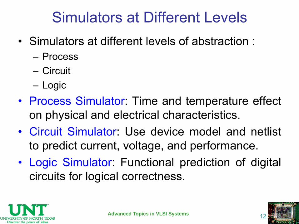
Simulators at Different Levels • Simulators at different levels of abstraction :
– Process – Circuit – Logic
• Process Simulator: Time and temperature effect on physical and electrical characteristics.
• Circuit Simulator: Use device model and netlist to predict current, voltage, and performance.
• Logic Simulator: Functional prediction of digital circuits for logical correctness.
Advanced Topics in VLSI Systems
12
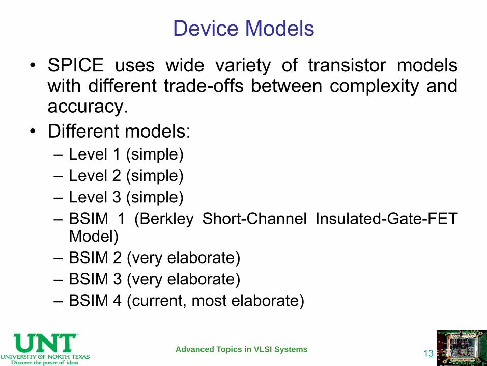
Device Models • SPICE uses wide variety of transistor models
with different trade-offs between complexity and accuracy.
• Different models: – Level 1 (simple) – Level 2 (simple) – Level 3 (simple) – BSIM 1 (Berkley Short-Channel Insulated-Gate-FET
Model) – BSIM 2 (very elaborate) – BSIM 3 (very elaborate) – BSIM 4 (current, most elaborate)
Advanced Topics in VLSI Systems
13
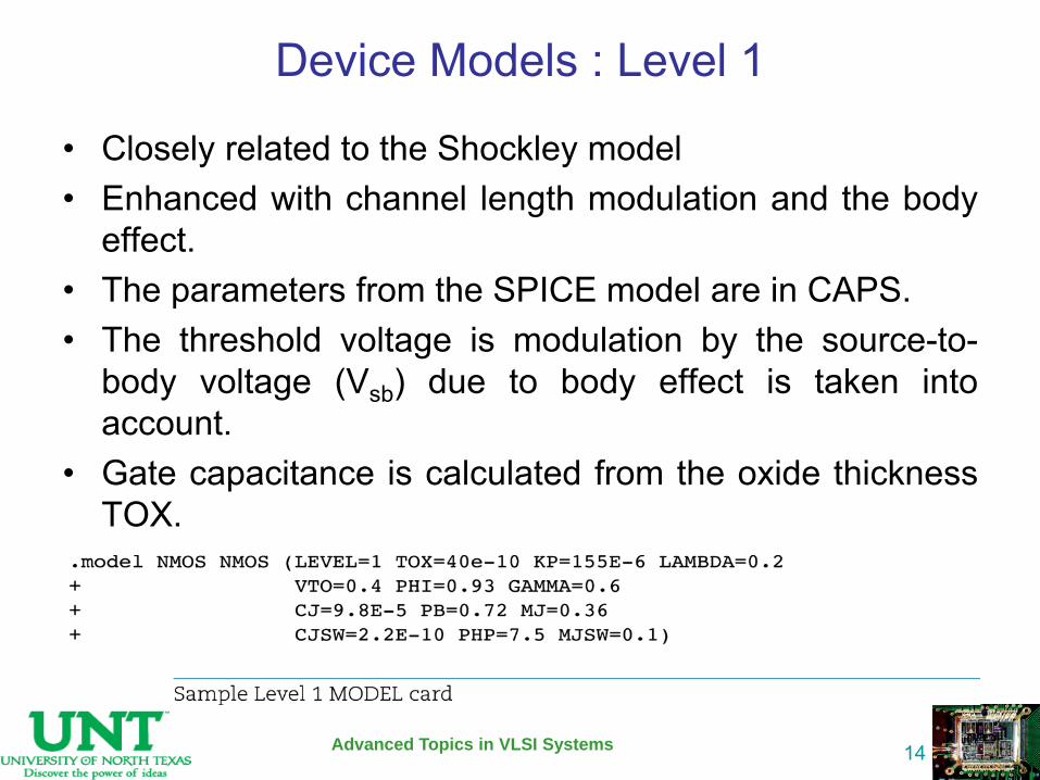
Device Models : Level 1
• Closely related to the Shockley model • Enhanced with channel length modulation and the body
effect. • The parameters from the SPICE model are in CAPS. • The threshold voltage is modulation by the source-to-
body voltage (Vsb) due to body effect is taken into account.
• Gate capacitance is calculated from the oxide thickness TOX.
Advanced Topics in VLSI Systems
14
Device Models : Level 2 and Level 3
• Account effects of : – Velocity Saturation – Mobility Degradation – Subthrehold Conduction – Drain-Induced Barrier Lowering
• Still not good enough to mimic the characteristics of the modern devices.
Advanced Topics in VLSI Systems
15
Device Models : BSIM
• Features of version 3v3: – Continuous and differentiable I-V characteristics for
different regions of operation for good convergence. – Sensitivity of Vt, etc to length and width – Vt model include body effect and DIBL. – Velocity saturation, mobility degradation, etc. – Multiple gate capacitance – Diffusion capacitance and resistance models
• Features of version 4: – Tunneling current – High-K dielectric
Advanced Topics in VLSI Systems
16
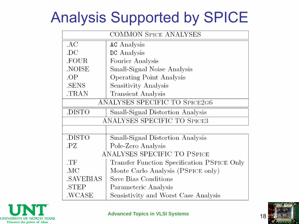
Analysis Supported by SPICE
• Types of Analysis DC Analysis AC Small-Signal Analysis Transient Analysis Pole-Zero Analysis Small-Signal Distortion Analysis Sensitivity Analysis Noise Analysis
Advanced Topics in VLSI Systems
17
Analysis Supported by SPICE
Advanced Topics in VLSI Systems
18
Analysis : DC The dc analysis portion of SPICE determines the dc
operating point of the circuit with inductors shorted and capacitors opened.
The dc analysis options are specified on the .DC, .TF, and .OP control lines.
A dc analysis is automatically performed prior to a transient analysis to determine the transient initial conditions, and prior to an ac small-signal analysis to determine the linearized, small-signal models for nonlinear devices.
Advanced Topics in VLSI Systems
19
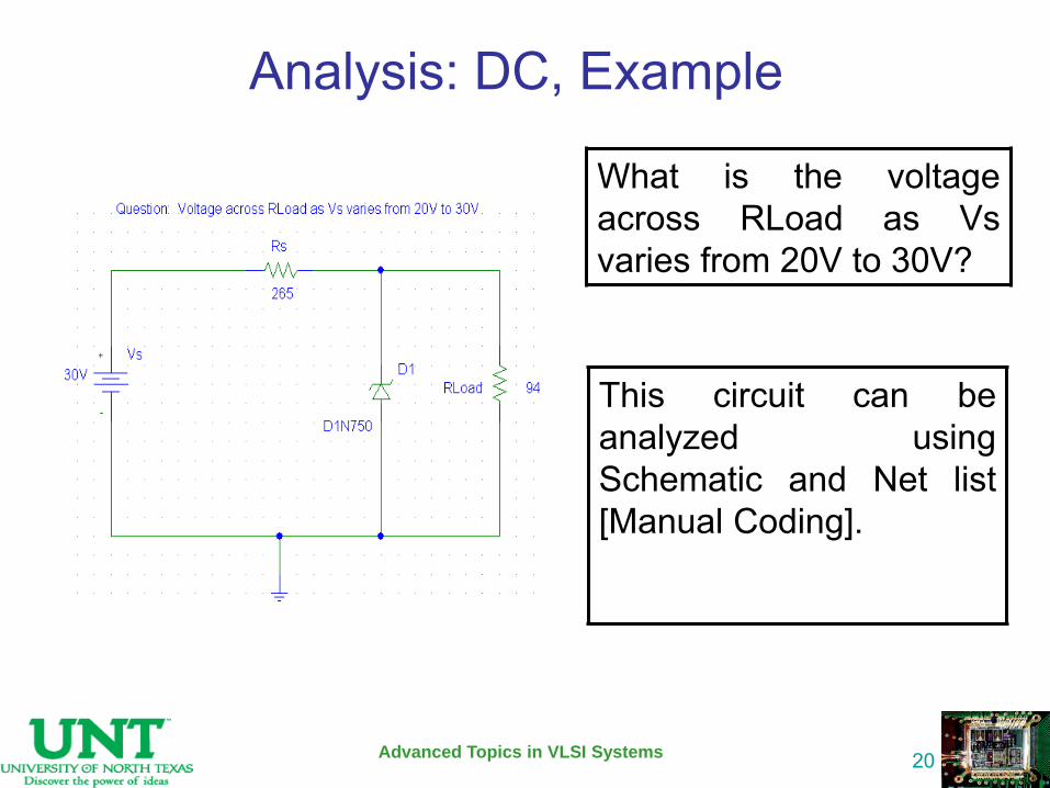
Analysis: DC, Example
This circuit can be analyzed using Schematic and Net list [Manual Coding].
Advanced Topics in VLSI Systems
20
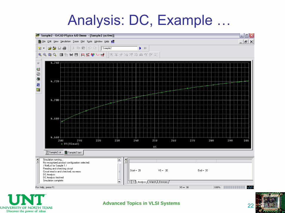
What is the voltage across RLoad as Vs varies from 20V to 30V?
Advanced Topics in VLSI Systems
21
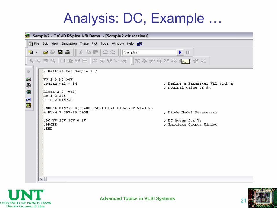
Analysis: DC, Example …
Advanced Topics in VLSI Systems
22
Analysis: DC, Example …
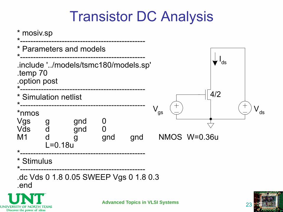
Transistor DC Analysis
Advanced Topics in VLSI Systems
23
* mosiv.sp *------------------------------------------------ * Parameters and models *------------------------------------------------ .include '../models/tsmc180/models.sp' .temp 70 .option post *------------------------------------------------ * Simulation netlist *------------------------------------------------ *nmos Vgs g gnd 0 Vds d gnd 0 M1 d g gnd gnd NMOS W=0.36u L=0.18u *------------------------------------------------ * Stimulus *------------------------------------------------ .dc Vds 0 1.8 0.05 SWEEP Vgs 0 1.8 0.3 .end
Vgs Vds
Ids
4/2
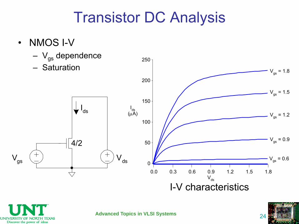
Transistor DC Analysis • NMOS I-V
– Vgs dependence – Saturation
Vgs Vds
Ids
4/2
Advanced Topics in VLSI Systems
24
Vds
0.0 0.3 0.6 0.9 1.2 1.5 1.8
Ids(A)
0
50
100
150
200
250
Vgs = 1.8
Vgs = 1.5
Vgs = 1.2
Vgs = 0.9
Vgs = 0.6
I-V characteristics
Analysis: AC Small Signal The ac small-signal portion of SPICE computes
the ac output variables as a function of frequency.
The ac analysis options are specified on the .AC control lines.
The program first computes the dc operating point of the circuit and determines linearized, small-signal models for all of the nonlinear devices in the circuit.
Advanced Topics in VLSI Systems
25
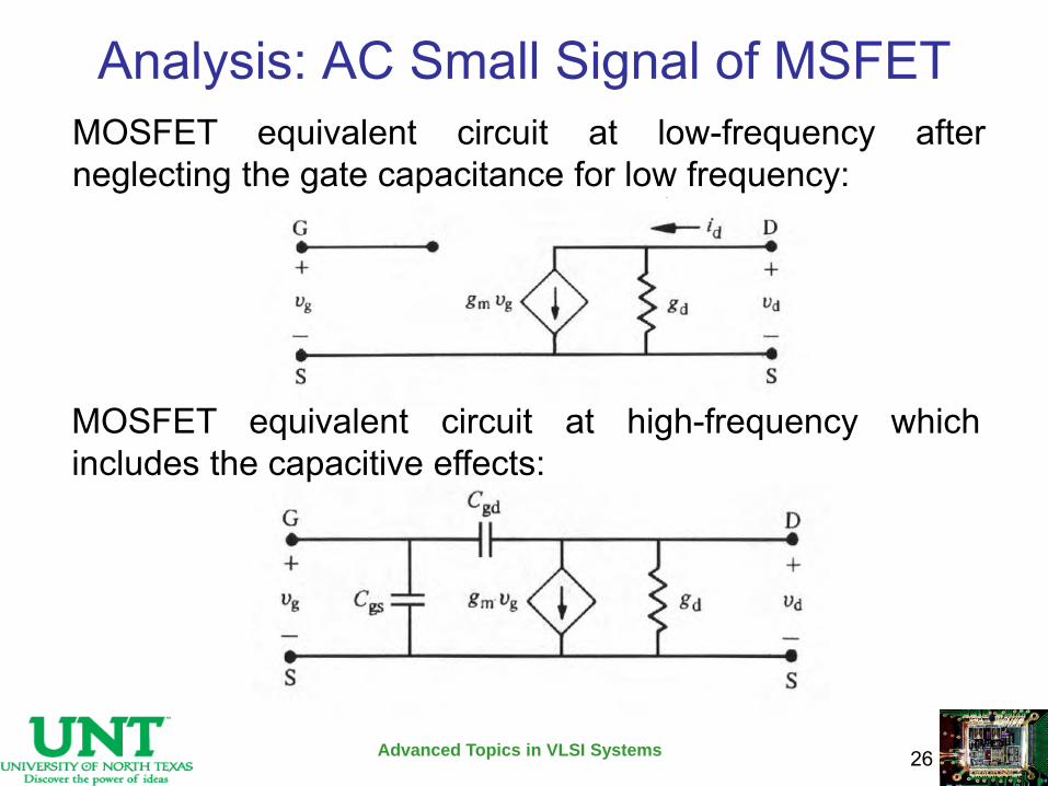
Analysis: AC Small Signal of MSFET
Advanced Topics in VLSI Systems
26
MOSFET equivalent circuit at low-frequency after neglecting the gate capacitance for low frequency:
MOSFET equivalent circuit at high-frequency which includes the capacitive effects:
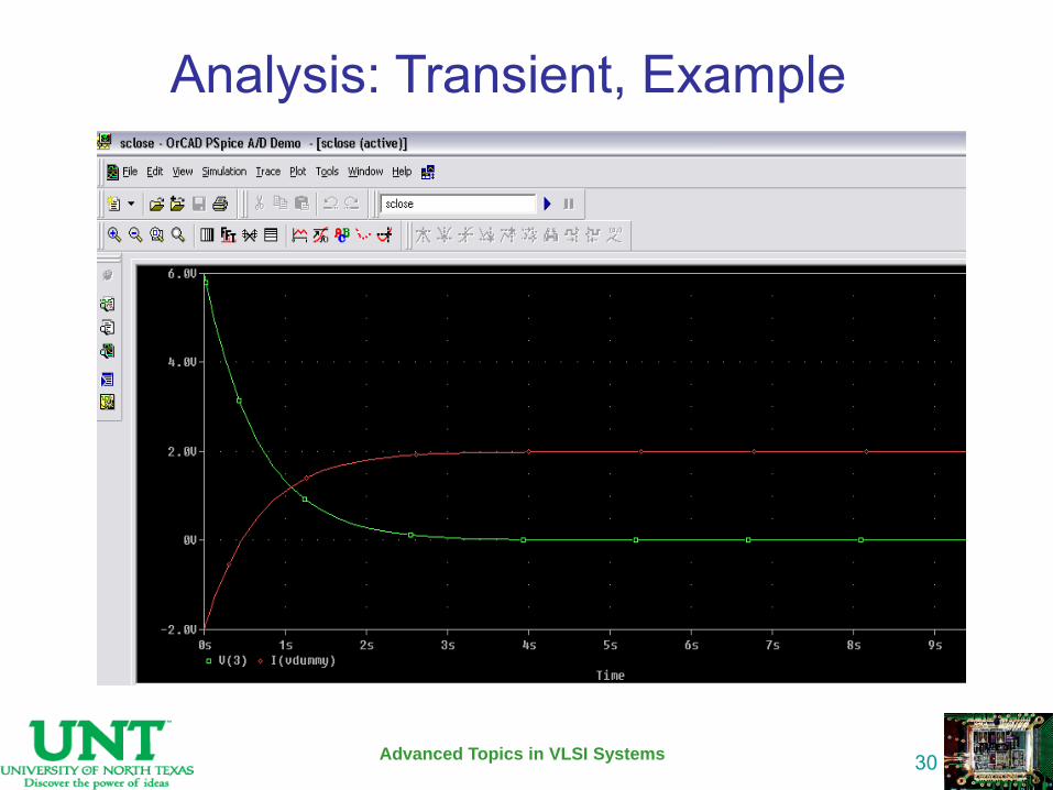
Analysis: Transient
The transient analysis portion of SPICE computes the transient output variables as a function of time over a user-specified time interval.
The transient time interval is specified on a .TRAN control line.
The initial conditions are automatically determined by a dc analysis.
Advanced Topics in VLSI Systems
27
Advanced Topics in VLSI Systems
28
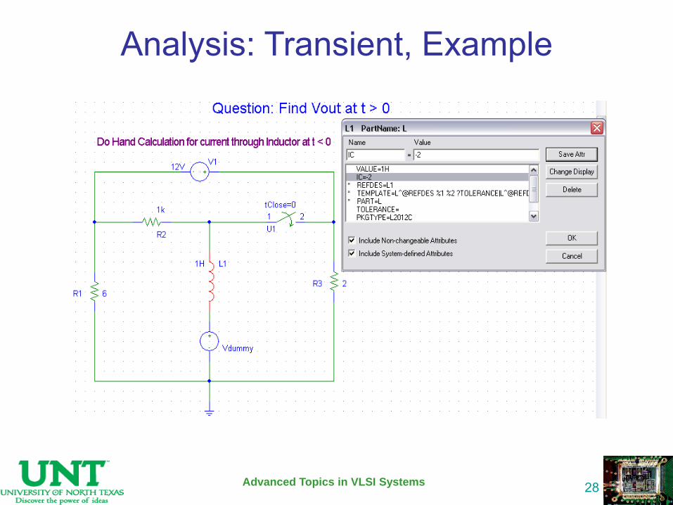
Analysis: Transient, Example
Advanced Topics in VLSI Systems
29
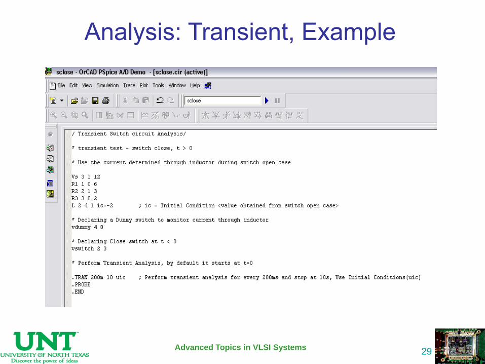
Analysis: Transient, Example
Advanced Topics in VLSI Systems
30
Analysis: Transient, Example
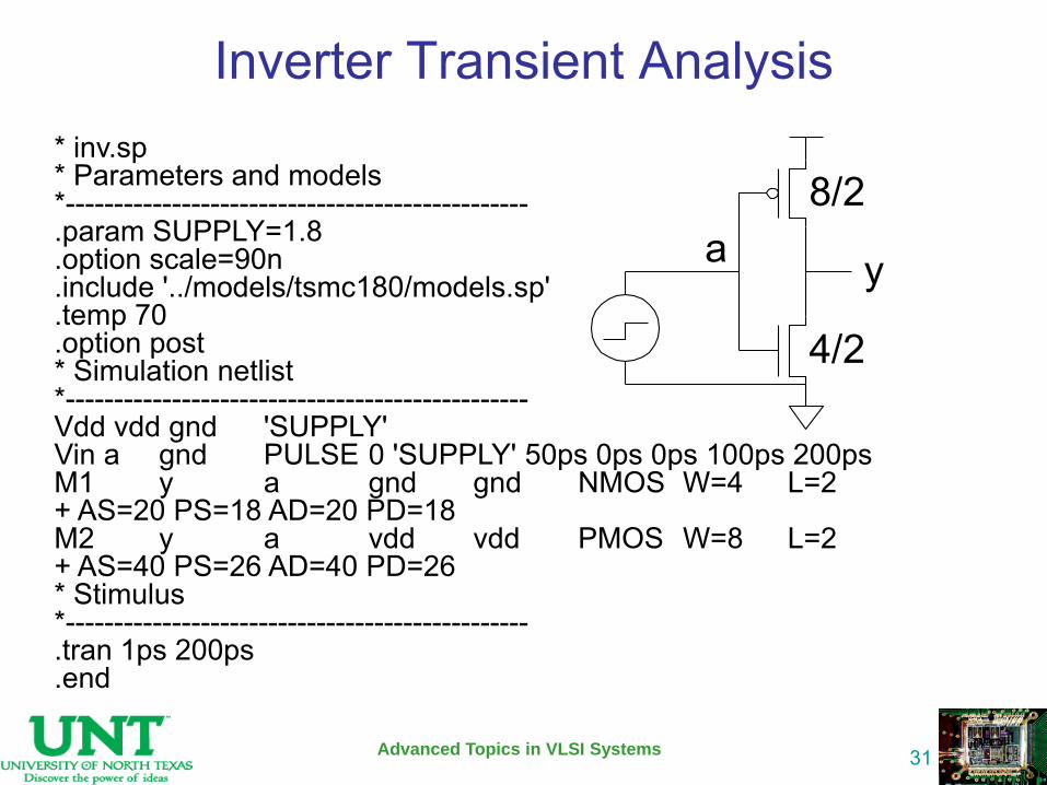
Inverter Transient Analysis
Advanced Topics in VLSI Systems
31
* inv.sp * Parameters and models *------------------------------------------------ .param SUPPLY=1.8 .option scale=90n .include '../models/tsmc180/models.sp' .temp 70 .option post * Simulation netlist *------------------------------------------------ Vdd vdd gnd 'SUPPLY' Vin a gnd PULSE 0 'SUPPLY' 50ps 0ps 0ps 100ps 200ps M1 y a gnd gnd NMOS W=4 L=2 + AS=20 PS=18 AD=20 PD=18 M2 y a vdd vdd PMOS W=8 L=2 + AS=40 PS=26 AD=40 PD=26 * Stimulus *------------------------------------------------ .tran 1ps 200ps .end
a y
4/2
8/2
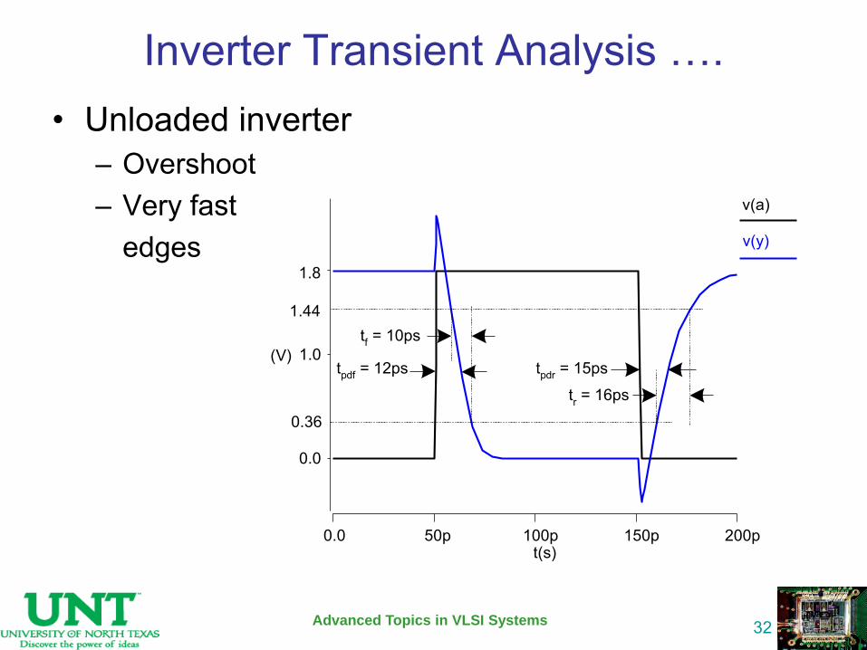
Inverter Transient Analysis …. • Unloaded inverter
– Overshoot – Very fast edges
Advanced Topics in VLSI Systems
32
(V)
0.0
1.0
t(s)0.0 50p 100p 150p 200p
v(a)
v(y)
tpdr = 15pstpdf = 12ps
tf = 10ps
tr = 16ps
0.36
1.44
1.8
Analysis: Pole-Zero
The pole-zero analysis portion of SPICE computes the poles and/or zeros in the small-signal ac transfer function.
The program first computes the dc operating point and then determines the linearized, small-signal models for all the nonlinear devices in the circuit.
Two types of transfer functions are allowed : one of the form (output voltage)/(input voltage) and the other of the form (output voltage)/(input current).
Advanced Topics in VLSI Systems
33

Analysis: Pole-Zero
Advanced Topics in VLSI Systems
34
In pole/zero analysis, a network is described by its network transfer function which, for any linear time-invariant network is of the form:
In the factorized form, the general function is:
The roots of the numerator N(s) (that is, zi) are called the zeros of the network function, and the roots of the denominator D(s) (that is, pj) are called the poles of the network function. S is a complex frequency.
The dynamic behavior of the network depends upon the location of the poles and zeros on the network function curve. The poles are called the natural frequencies of the network.
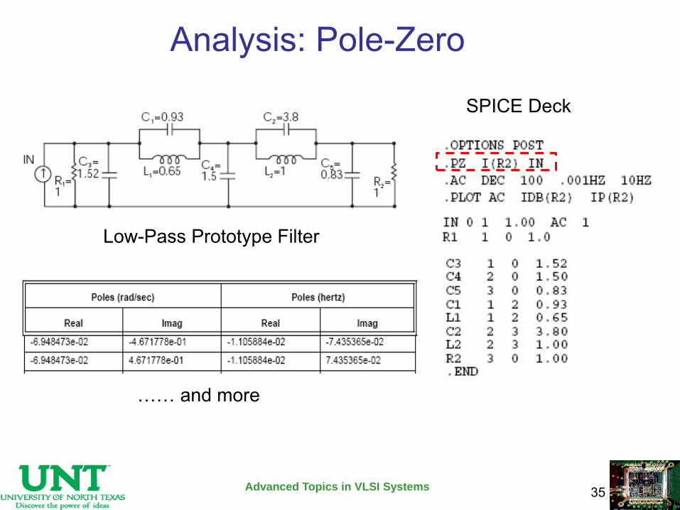
Analysis: Pole-Zero
Advanced Topics in VLSI Systems
35
Low-Pass Prototype Filter
SPICE Deck
…… and more
Analysis: Small-Signal Distortion
The distortion analysis portion of SPICE computes steady-state harmonic and inter-modulation products for small input signal magnitudes.
Distortion analysis is supported for the following nonlinear devices: diodes (DIO), BJT, JFET, MOSFETs (levels 1, 2, 3, 4/BSIM1, 5/BSIM2, and 6) and MESFETs.
All linear devices are automatically supported by distortion analysis.
Advanced Topics in VLSI Systems
36
Analysis: Small-Signal Distortion
Advanced Topics in VLSI Systems
37
The .DISTO statement computes the distortion characteristics of the circuit in an AC small-signal, sinusoidal, steady-state analysis.
SPICE computes and reports five distortion measures at the specified load resistor. The analysis is performed assuming that one or two signal frequencies are imposed at the input.
Syntax
Rload -- the resistor element name, inter -- interval at which a distortion-measure summary is to be printed Skw2-- ratio of second frequency F2 to nominal analysis frequency F1 refpwr -- reference power level spwf -- amplitude of the second frequency
Example
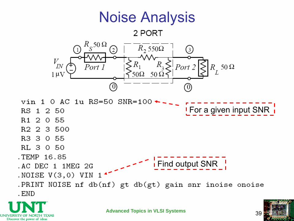
Noise Analysis
• The noise analysis portion of SPICE does analysis device-generated noise for the given circuit.
• When provided with an input source and an output port, the analysis calculates the noise contributions of each device (and each noise generator within the device) to the output port voltage.
• It also calculates the input noise to the circuit, equivalent to the output noise referred to the specified input source.
Advanced Topics in VLSI Systems
38
Noise Analysis
Advanced Topics in VLSI Systems
39
For a given input SNR
Find output SNR
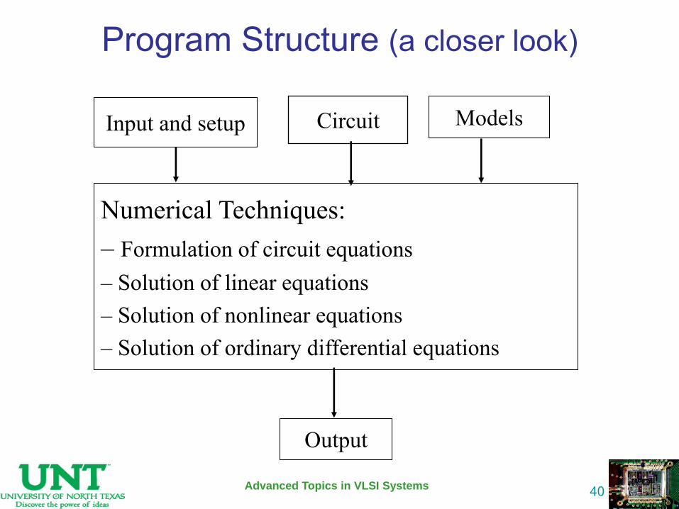
Program Structure (a closer look)
Advanced Topics in VLSI Systems
40
Input and setup Models
Numerical Techniques: – Formulation of circuit equations – Solution of linear equations – Solution of nonlinear equations – Solution of ordinary differential equations
Output
Circuit
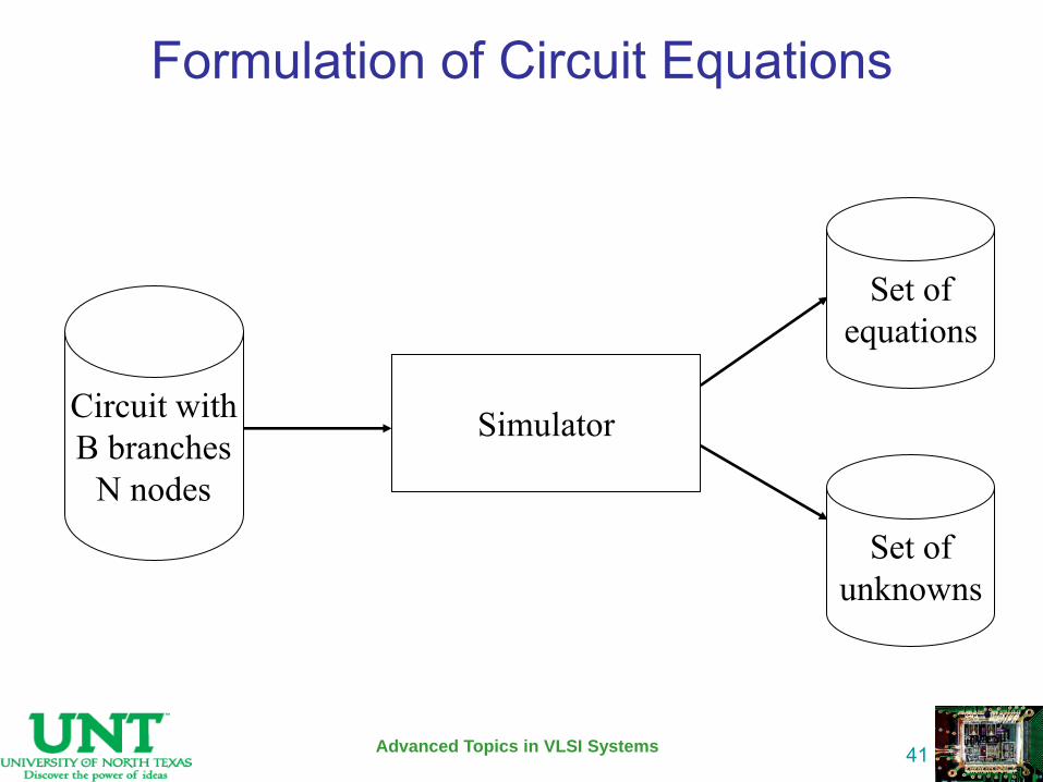
Formulation of Circuit Equations
Advanced Topics in VLSI Systems
41
Circuit with B branches
N nodes
Simulator
Set of equations
Set of unknowns
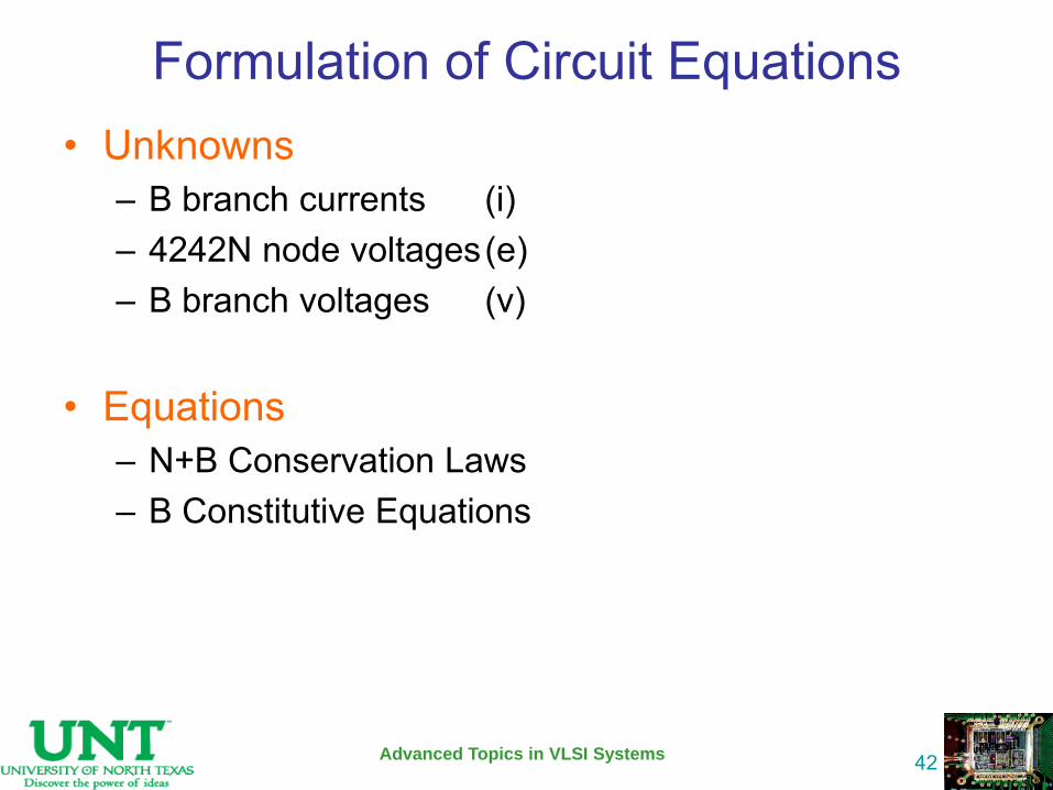
Formulation of Circuit Equations • Unknowns
– B branch currents (i) – 4242N node voltages (e) – B branch voltages (v)
• Equations – N+B Conservation Laws – B Constitutive Equations
Advanced Topics in VLSI Systems
42
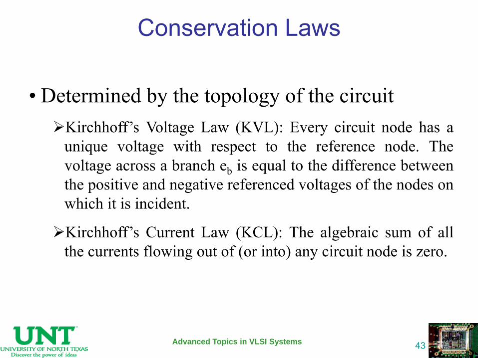
Conservation Laws
Advanced Topics in VLSI Systems
43
• Determined by the topology of the circuit Kirchhoff’s Voltage Law (KVL): Every circuit node has a
unique voltage with respect to the reference node. The voltage across a branch eb is equal to the difference between the positive and negative referenced voltages of the nodes on which it is incident.
Kirchhoff’s Current Law (KCL): The algebraic sum of all the currents flowing out of (or into) any circuit node is zero.
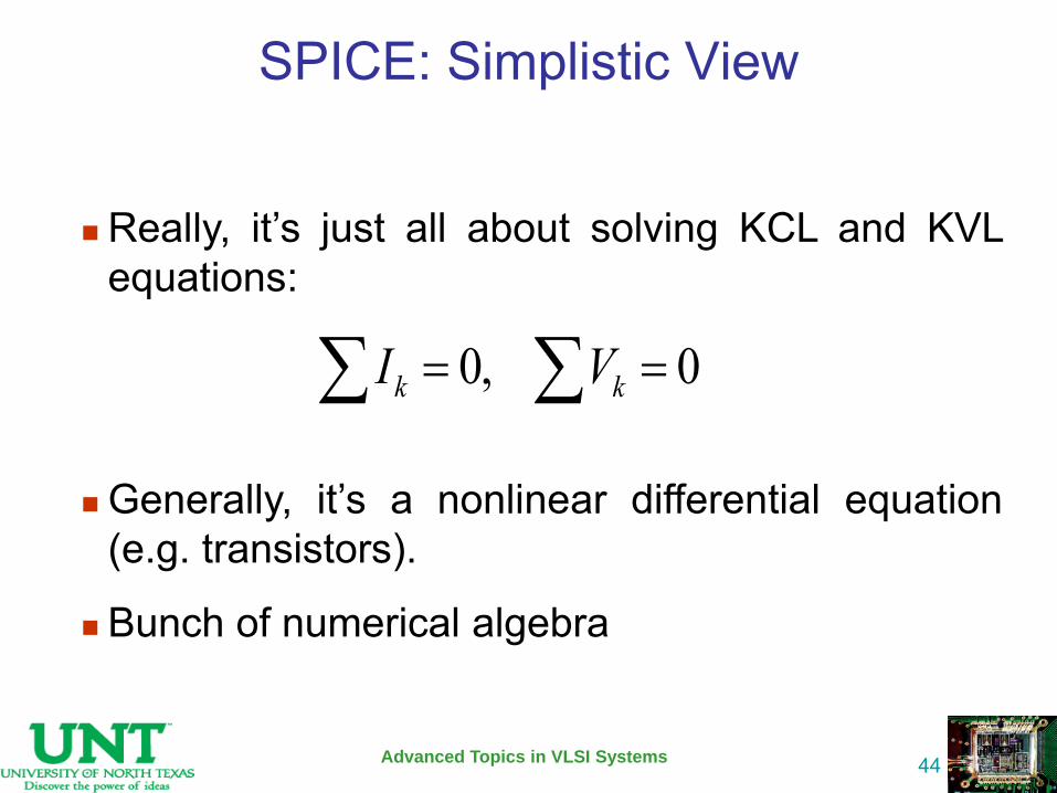
SPICE: Simplistic View
Advanced Topics in VLSI Systems
44
Really, it’s just all about solving KCL and KVL equations:
Generally, it’s a nonlinear differential equation (e.g. transistors).
Bunch of numerical algebra
0,0 kk VI
Branch Constitutive Equations (BCE) • Determined by the mathematical model of the
electrical behavior of a component – Example: V=R·I
• In most of circuit simulators this mathematical
model is expressed in terms of ideal elements
Advanced Topics in VLSI Systems
45
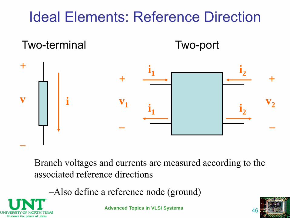
Ideal Elements: Reference Direction
Advanced Topics in VLSI Systems
46
+
_
v i
Two-terminal
+
_
v1
i1
Two-port
i1
+
_
v2
i2
i2
Branch voltages and currents are measured according to the associated reference directions
–Also define a reference node (ground)
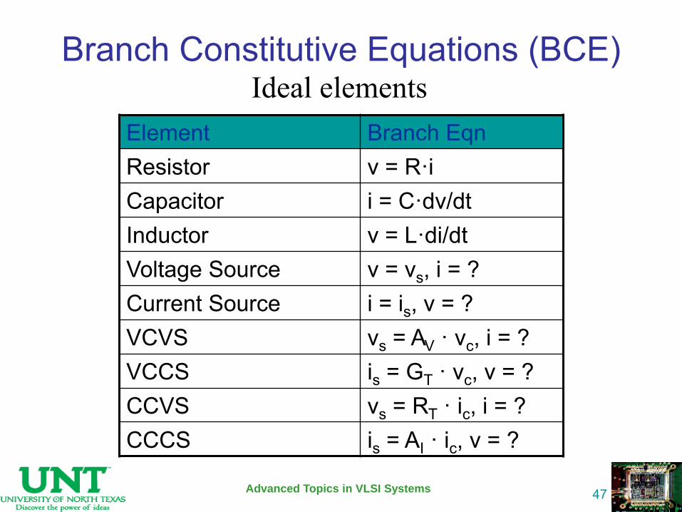
Branch Constitutive Equations (BCE)
Advanced Topics in VLSI Systems
47
Ideal elements Element Branch Eqn Resistor v = R·i Capacitor i = C·dv/dt Inductor v = L·di/dt Voltage Source v = vs, i = ? Current Source i = is, v = ? VCVS vs = AV · vc, i = ? VCCS is = GT · vc, v = ? CCVS vs = RT · ic, i = ? CCCS is = AI · ic, v = ?
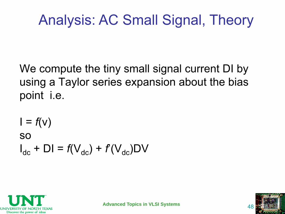
We compute the tiny small signal current DI by using a Taylor series expansion about the bias point i.e. I = f(v) so Idc + DI = f(Vdc) + f’(Vdc)DV
Advanced Topics in VLSI Systems
48
Analysis: AC Small Signal, Theory
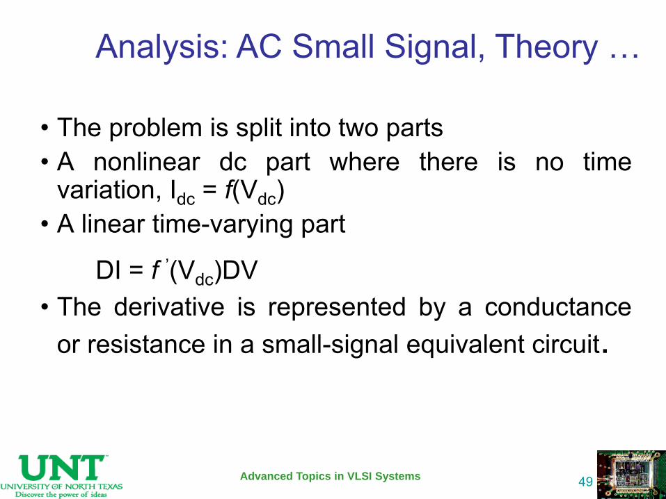
• The problem is split into two parts • A nonlinear dc part where there is no time
variation, Idc = f(Vdc) • A linear time-varying part
DI = f ’(Vdc)DV • The derivative is represented by a conductance
or resistance in a small-signal equivalent circuit.
Advanced Topics in VLSI Systems
49
Analysis: AC Small Signal, Theory …
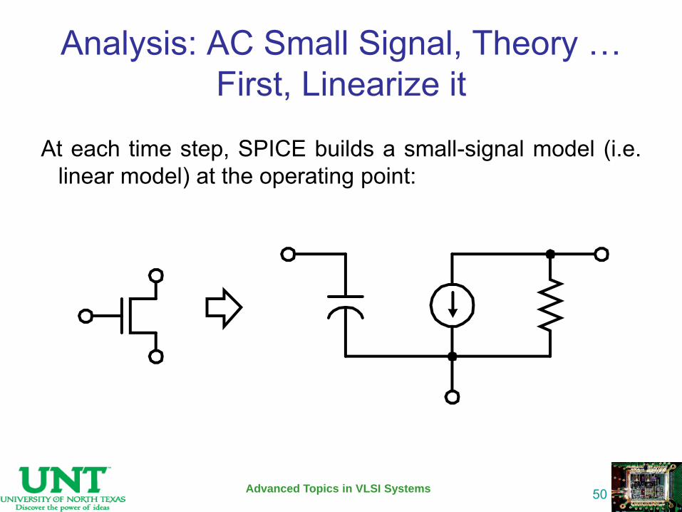
Analysis: AC Small Signal, Theory … First, Linearize it
Advanced Topics in VLSI Systems
50
At each time step, SPICE builds a small-signal model (i.e. linear model) at the operating point:
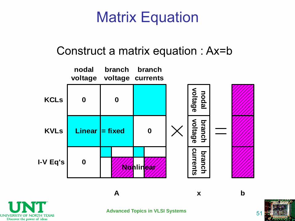
Matrix Equation
Advanced Topics in VLSI Systems
51
Construct a matrix equation : Ax=b
0 0
Linear = fixed 0
0
KCLs
KVLs
I-V Eq's
nodal
voltage
branch
voltage
branch
currents
no
dal
vo
ltag
e
bra
nc
h
vo
ltag
e
bra
nc
h
cu
rren
ts
A x b
Nonlinear

Methods for Linear & Non-Linear Systems
Advanced Topics in VLSI Systems
52
•Systems of linear equations –Existence and uniqueness review –Gaussian Elimination basics
•LU factorization •Pivoting
•Nonlinear problems •Iterative Methods •Newton’s Method
–Derivation of Newton –Quadratic Convergence –Examples
Systems of Linear Equations
Advanced Topics in VLSI Systems
53
•Problem to solve: M x = b
•Given M x = b : –Is there a solution?
–Is the solution unique?
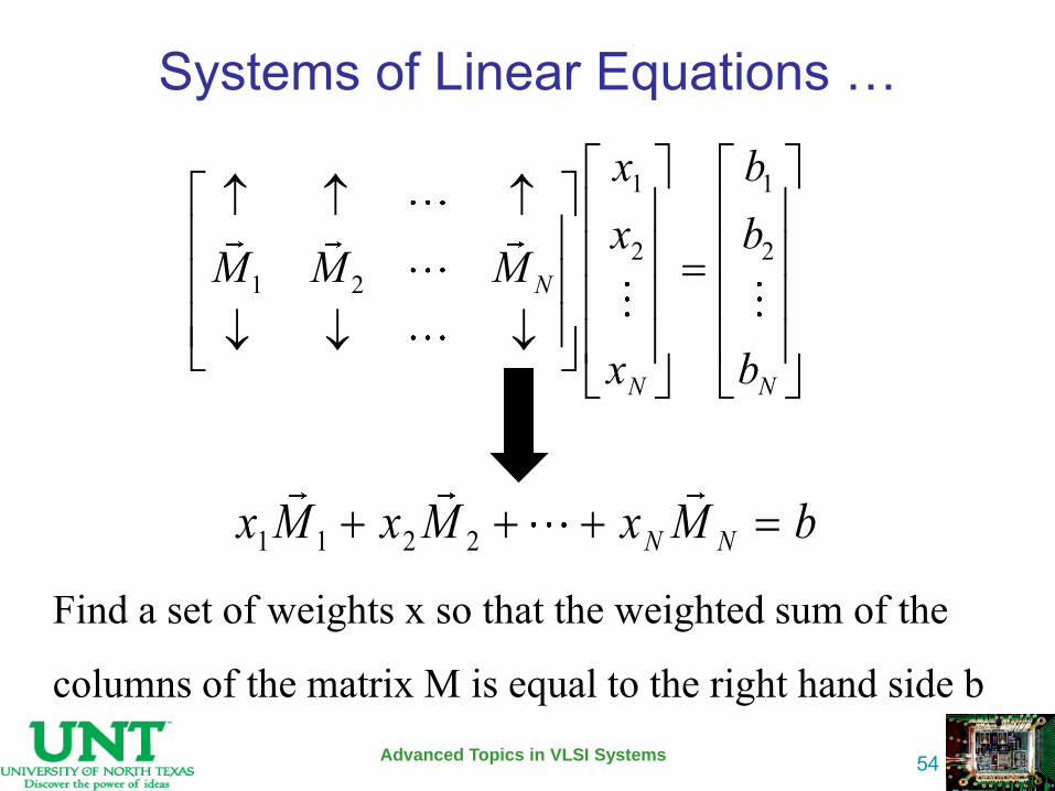
Systems of Linear Equations …
Advanced Topics in VLSI Systems
54
1 1
2 21 2 N
N N
x bx b
M M M
x b
1 1 2 2 N Nx M x M x M b
Find a set of weights x so that the weighted sum of the
columns of the matrix M is equal to the right hand side b

Systems of Linear Equations - Existence
Advanced Topics in VLSI Systems
55
A solution exists if:
There exist weights, x1, …., xN, such that:
bMxMxMx NN ...2211
A solution exists when b is in the span of the columns of M
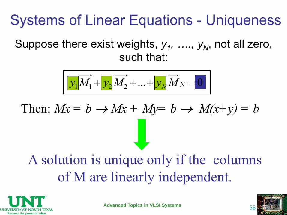
Suppose there exist weights, y1, …., yN, not all zero, such that:
Advanced Topics in VLSI Systems
56
A solution is unique only if the columns of M are linearly independent.
Then: Mx = b Mx + My= b M(x+y) = b
0...2211 NN MyMyMy
Systems of Linear Equations - Uniqueness
Methods for Solving Linear Equations
Advanced Topics in VLSI Systems
57
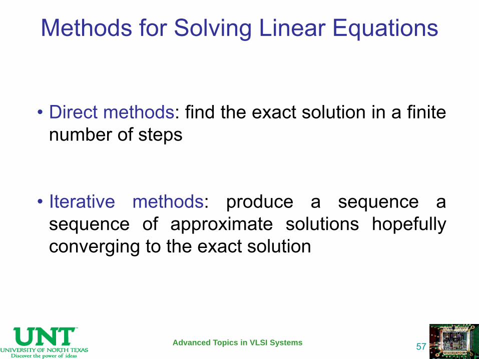
• Direct methods: find the exact solution in a finite number of steps
• Iterative methods: produce a sequence a sequence of approximate solutions hopefully converging to the exact solution
Gaussian Elimination Basics
Advanced Topics in VLSI Systems
58
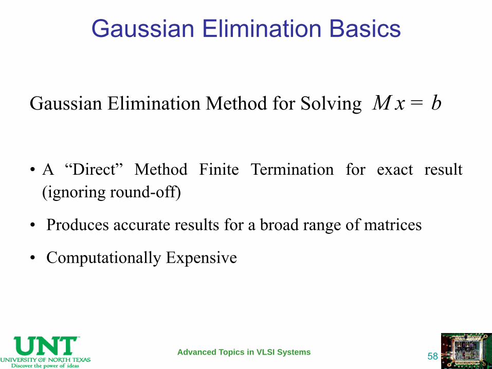
Gaussian Elimination Method for Solving M x = b
• A “Direct” Method Finite Termination for exact result (ignoring round-off)
• Produces accurate results for a broad range of matrices
• Computationally Expensive
Gaussian Elimination (GE) Basics
Advanced Topics in VLSI Systems
59
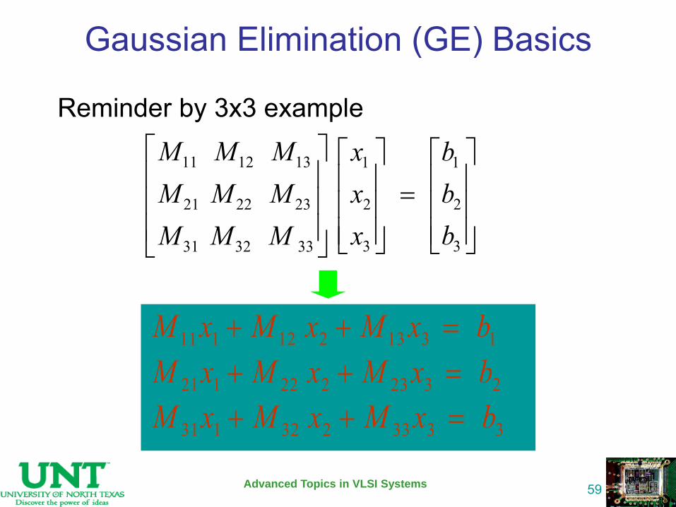
Reminder by 3x3 example
11 12 13 1 1
21 22 23 2 2
3 331 32 33
M M M x bM M M x b
x bM M M
11 1 12 2 13 3 1M x M x M x b
21 1 22 2 23 3 2M x M x M x b
31 1 32 2 33 3 3M x M x M x b
GE Basics – Key idea in the matrix
Advanced Topics in VLSI Systems
60
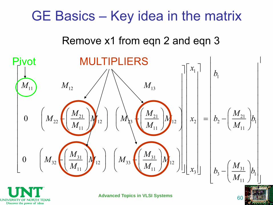
Remove x1 from eqn 2 and eqn 3
11
11 12 13
21 21 2122 12 23 12 2 2 1
11 11 11
31 3132 12 33 12
311 11 3 3
0
0
x bM M M
M M MM M M M x b bM M M
M MM M M MMM M x b
1
111
bM
MULTIPLIERS Pivot
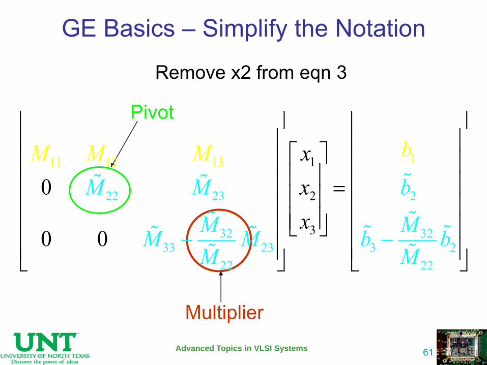
GE Basics – Simplify the Notation
Advanced Topics in VLSI Systems
61
Remove x2 from eqn 3
Pivot
Multiplier
22 23 2
32 3233 23 3 2
111 12 13
2 2
1
2
3
2 2
0
0 0
xM M b
M MM M b bM M
bM
x
Mx
M
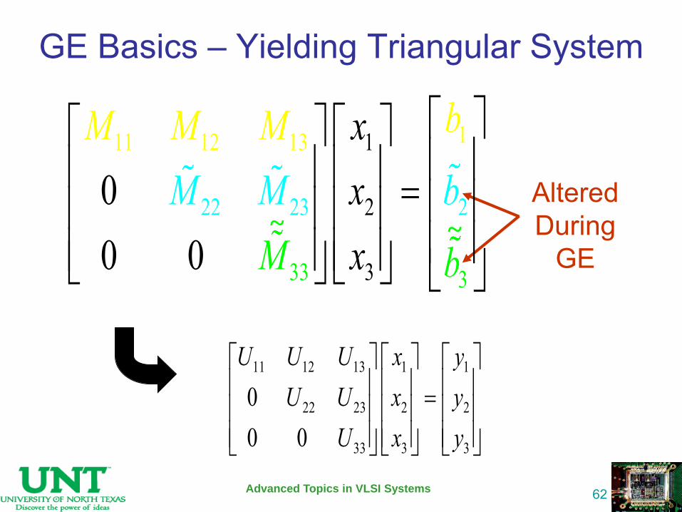
GE Basics – Yielding Triangular System
Advanced Topics in VLSI Systems
62
Altered During
GE
11 12 13 1 1
22 23 2 2
33 3 3
00 0
U U U x yU U x y
U x y
11
2
3
22
11 12 1
2
3
2
3 3
3
300 0
xM M b
b
M
M M Mxx b
~ ~
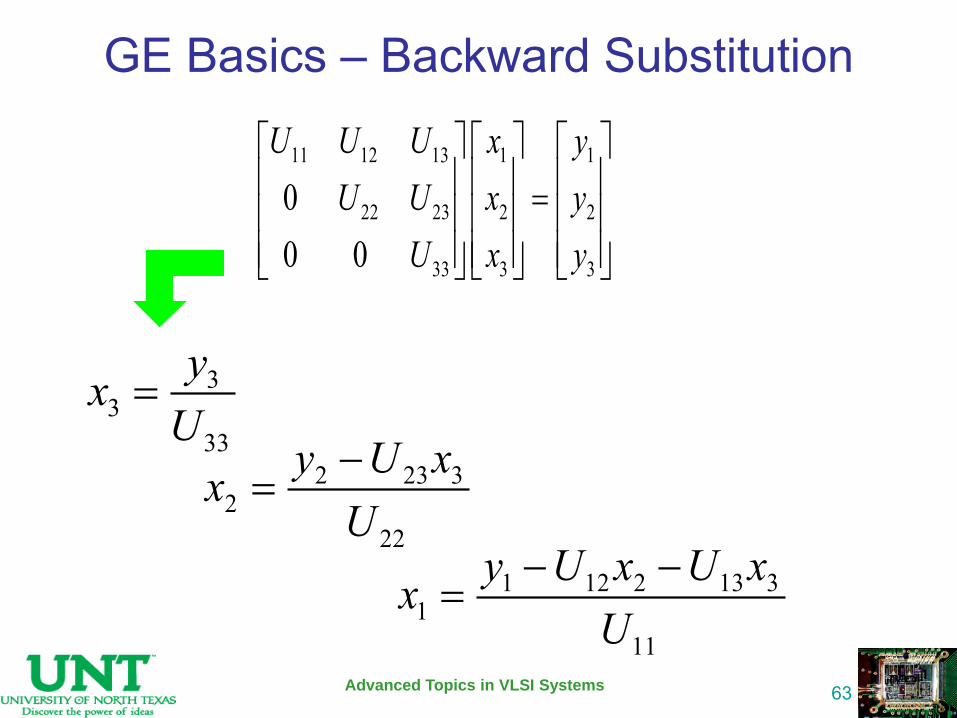
GE Basics – Backward Substitution
Advanced Topics in VLSI Systems
63
33
33
yxU
2 23 32
22
y U xxU
11 12 13 1 1
22 23 2 2
33 3 3
00 0
U U U x yU U x y
U x y
1 12 2 13 31
11
y U x U xxU
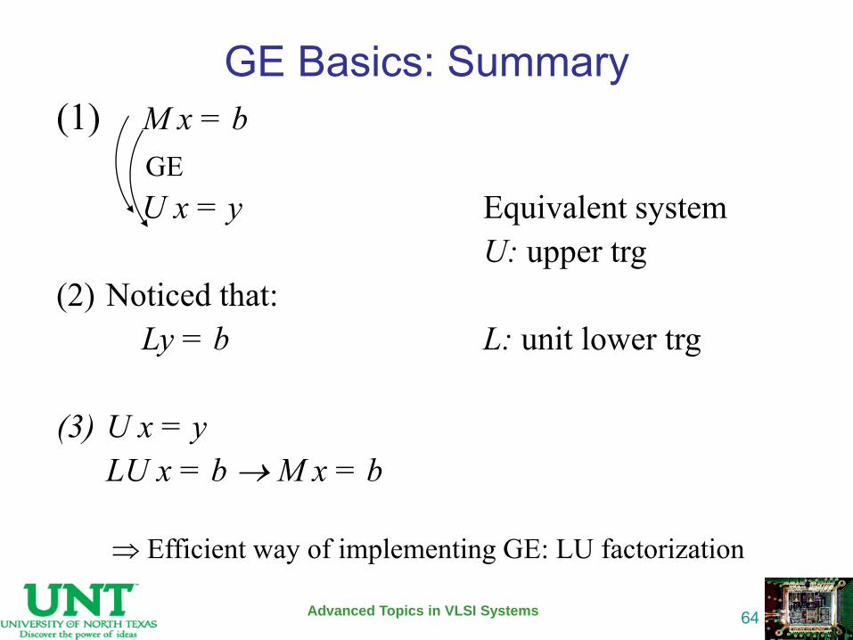
GE Basics: Summary
Advanced Topics in VLSI Systems
64
(1) M x = b U x = y Equivalent system U: upper trg (2) Noticed that: Ly = b L: unit lower trg (3) U x = y LU x = b M x = b
GE
Efficient way of implementing GE: LU factorization
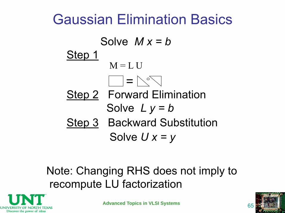
Gaussian Elimination Basics
Advanced Topics in VLSI Systems
65
Solve M x = b Step 1 Step 2 Forward Elimination Solve L y = b Step 3 Backward Substitution Solve U x = y
= M = L U
Note: Changing RHS does not imply to recompute LU factorization
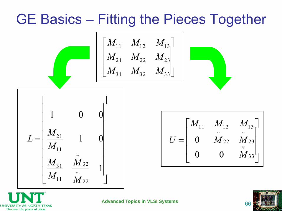
GE Basics – Fitting the Pieces Together
Advanced Topics in VLSI Systems
66
333231
232221
131211
MMMMMMMMM
33
23~
22~
131211
000
MMM
MMM
U
1
01
001
22
~32
~
11
31
11
21
M
MMM
MML
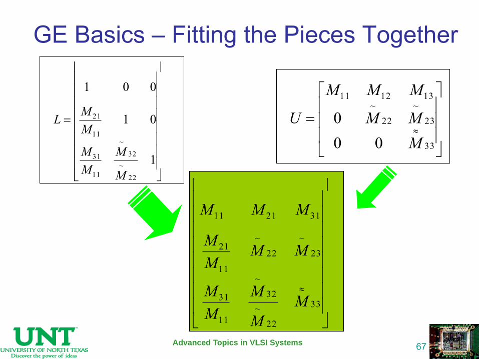
GE Basics – Fitting the Pieces Together
Advanced Topics in VLSI Systems
67
33
23~
22~
131211
000
MMM
MMM
U
1
01
001
22
~32
~
11
31
11
21
M
MMM
MML
33
22
~32
~
11
31
23
~
22
~
11
21
312111
MM
MMM
MMMM
MMM
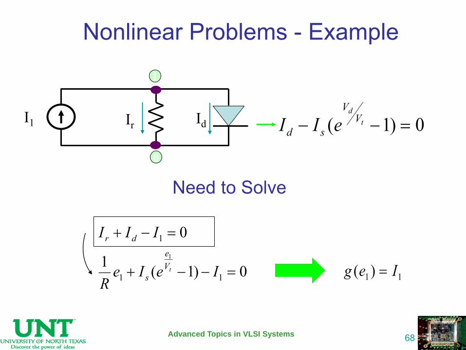
Nonlinear Problems - Example
Advanced Topics in VLSI Systems
68
Need to Solve
( 1) 0d
t
VV
d sI I e
0
1
Ir I1 Id
0)1(1
0
11
1
1
IeIeR
III
tVe
s
dr
11 )( Ieg
Nonlinear Equations
Advanced Topics in VLSI Systems
69
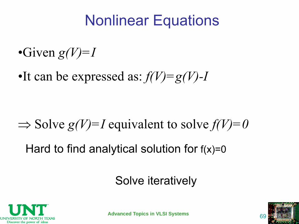
Hard to find analytical solution for f(x)=0
Solve iteratively
•Given g(V)=I
•It can be expressed as: f(V)=g(V)-I
Solve g(V)=I equivalent to solve f(V)=0
Nonlinear Equations – Iterative Methods
Advanced Topics in VLSI Systems
70
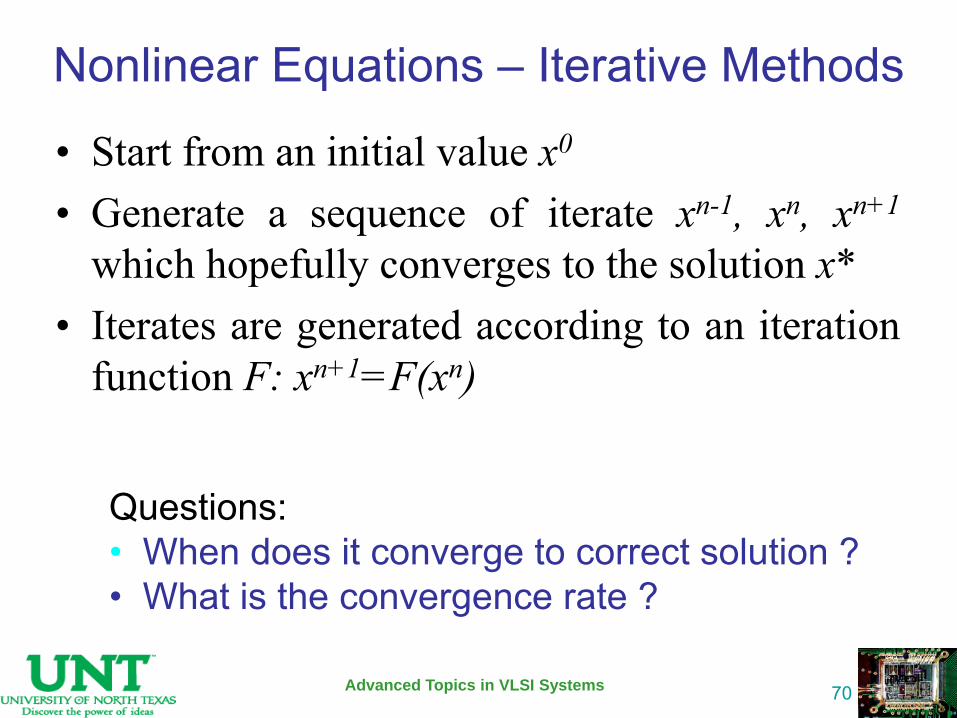
• Start from an initial value x0
• Generate a sequence of iterate xn-1, xn, xn+1 which hopefully converges to the solution x*
• Iterates are generated according to an iteration function F: xn+1=F(xn)
Questions: • When does it converge to correct solution ? • What is the convergence rate ?
Newton-Raphson (NR) Method
Advanced Topics in VLSI Systems
71
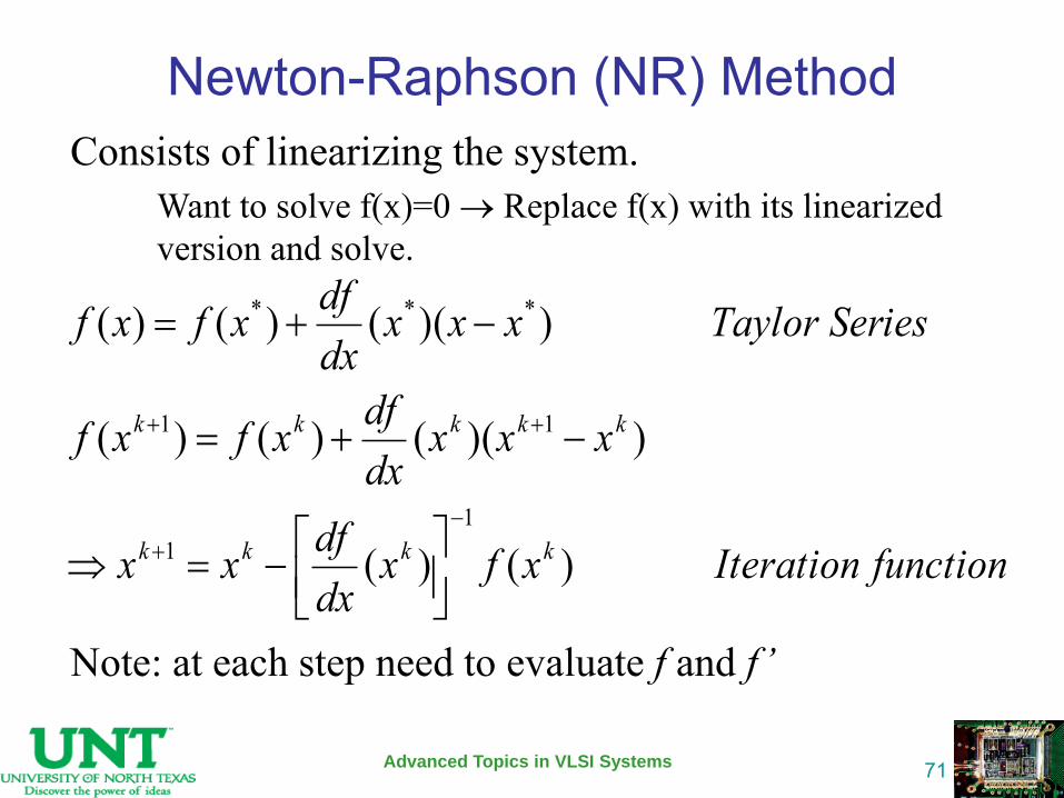
Consists of linearizing the system. Want to solve f(x)=0 Replace f(x) with its linearized
version and solve. Note: at each step need to evaluate f and f ’
functionIterationxfxdxdfxx
xxxdxdfxfxf
iesTaylor Serxxxdxdfxfxf
kkkk
kkkkk
)()(
))(()()(
))(()()(
11
11
***
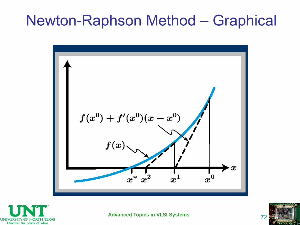
Newton-Raphson Method – Graphical
Advanced Topics in VLSI Systems
72
Newton-Raphson Method – Algorithm
Advanced Topics in VLSI Systems
73
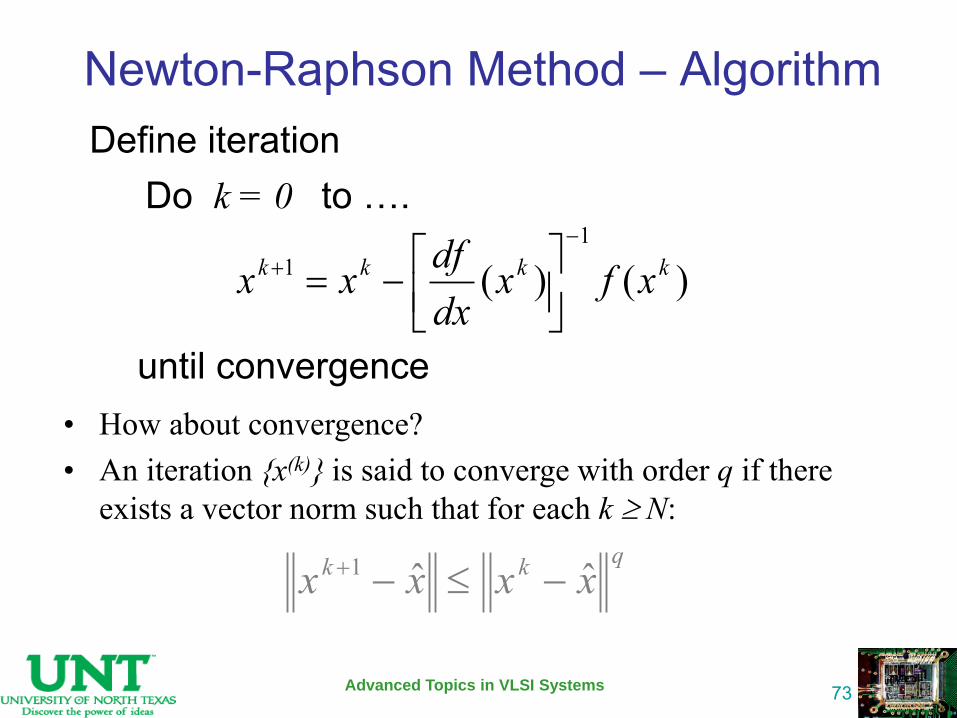
Define iteration Do k = 0 to ….
until convergence • How about convergence? • An iteration {x(k)} is said to converge with order q if there
exists a vector norm such that for each k N: qkk xxxx ˆˆ1
)()(1
1 kkkk xfxdxdfxx
Newton-Raphson Method – Convergence
Advanced Topics in VLSI Systems
74
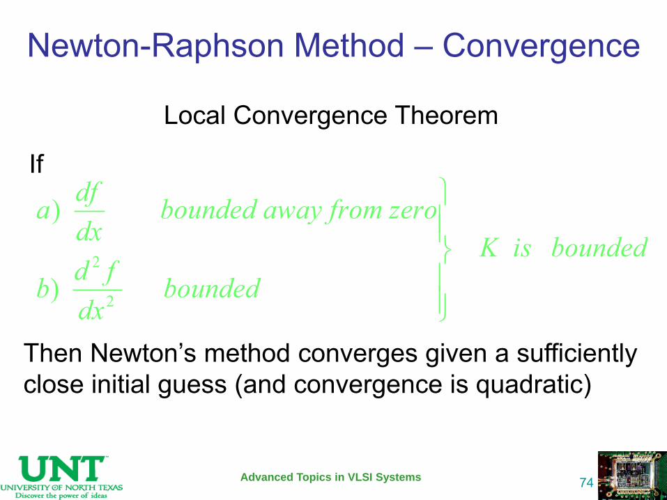
Local Convergence Theorem
If
Then Newton’s method converges given a sufficiently close initial guess (and convergence is quadratic)
boundedisKbounded
dxfdb
roay from zebounded awdxdfa
)
)
2
2
Newton-Raphson Method – Convergence
Advanced Topics in VLSI Systems
75
Reference
Advanced Topics in VLSI Systems
76
• http://bwrc.eecs.berkeley.edu/Classes/IcBook/SPICE/UserGuide/overview_fr.html
• http://bear.ces.cwru.edu/eecs_cad/cad_spice.html • http://mos.stanford.edu/papers/jk_fspice.ppt • http://www.ecircuitcenter.com/AboutSPICE.htm • http://www-
cad.eecs.berkeley.edu/~nardi/EE219A/lectures/ • http://www.ieee.uta.edu/Tutorials/pspice/Basic%20
Tuto.ppt