
Lecture 3 PHY and Cross -Layer Designwmnlab.ee.ntu.edu.tw/951cross/Lec3_morePHY.pdfLecture 3 PHY and...
51
Lecture 3 PHY and Cross Lecture 3 PHY and Cross - - Layer Layer Design Design Hung-Yu Wei National Taiwan University
Transcript of Lecture 3 PHY and Cross -Layer Designwmnlab.ee.ntu.edu.tw/951cross/Lec3_morePHY.pdfLecture 3 PHY and...

Lecture 3 PHY and CrossLecture 3 PHY and Cross--Layer Layer DesignDesign
Hung-Yu WeiNational Taiwan University
CodingCoding

3
Classification of Channel codingClassification of Channel coding• FEC (forward error correction) codes
– Contain redundant information to correct errors
– Block coding• Fixed block size information bits
• E.g. Hamming, BCH, Reed-Solomon
– Convolutional coding• Variable-length information bit stream
• E.g. Trellis
• ARQ (Automatic Repeat Request) codes– Do not contain information to correct errors
– Detect errors and ask for frame retransmission
– Use jointly with Layer-2 ARQ protocol
– E.g. Parity, CRC

4
((j,kj,k) code) code• Notation
– We say a coding scheme is a (j,k) code if• Input j bits
• Output k bits
• j < k
– For block code Another notation: (N,K,T) code
•N=number of overall bits after encoding
•K=# of data bits
•T=#of data bits could be corrected
For example: RS(N=255, K=239, T=8)

5
ParityParity• Simplest way to detect error
– Foundation for many other block codes
• (j,j+1) code– 1 parity bit
• Detection at receiver– XOR
• Even parity– After adding parity bit, total # of 1 bits is
even.
• Odd parity– Total # of 1 bits is odd

6
CRC codesCRC codes• Cyclic redundancy check
• ARQ protocol uses CRC codes to detect error in a data block
CRC-5 code

7
Selecting a coding schemeSelecting a coding scheme• Depending on the communication channel
property, we should consider these factors– Target bit-error-rate– Degree of burst of errors– L2 re-transmission mechanism
• ARQ protocol scheme• Number of re-transmission• Frame size� mapping BER to FER
– Transmission overhead• how many redundant bits
– Computational complexity– Cost of implementation on ICs

8
New trend: joint source coding and New trend: joint source coding and channel codingchannel coding
• Traditionally, source coding and channel coding are done independently
• New research direction– Design and optimize source & channel coding
• Tradeoff– Scalability
– Complexity
– Optimal capacity
9
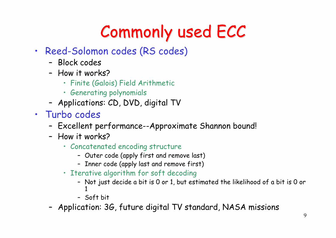
Commonly used ECCCommonly used ECC• Reed-Solomon codes (RS codes)
– Block codes– How it works?
• Finite (Galois) Field Arithmetic• Generating polynomials
– Applications: CD, DVD, digital TV
• Turbo codes– Excellent performance--Approximate Shannon bound!– How it works?
• Concatenated encoding structure – Outer code (apply first and remove last)– Inner code (apply last and remove first)
• Iterative algorithm for soft decoding – Not just decide a bit is 0 or 1, but estimated the likelihood of a bit is 0 or
1– Soft bit
– Application: 3G, future digital TV standard, NASA missions

CrossCross--Layer Design and Layer Design and OptimizationOptimization

11
TradeoffsTradeoffs• Robustness of ECCs
– High redundancy
– Strong error resilience
• Transmission rate– Overhead/redundancy reduces effective data rates
• Computational complexity– Some ECCs is computational intensive
– Processing time � additional delay
– Limited computational power at handheld devices
– Computational complexity � more power consumption
12
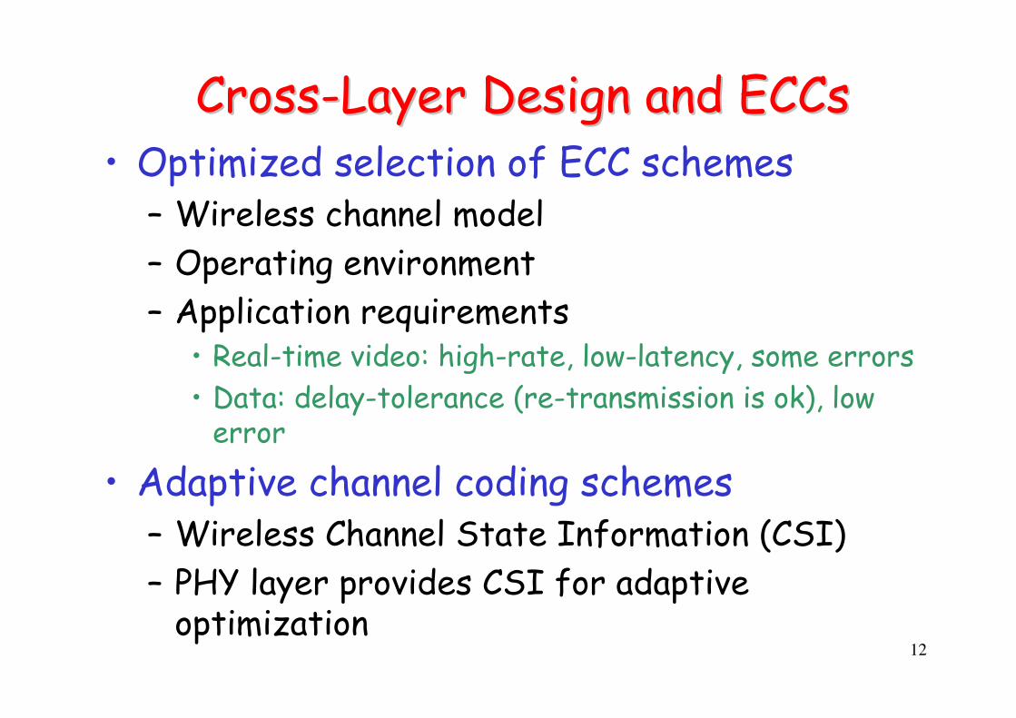
CrossCross--Layer Design and Layer Design and ECCsECCs• Optimized selection of ECC schemes
– Wireless channel model
– Operating environment
– Application requirements• Real-time video: high-rate, low-latency, some errors
• Data: delay-tolerance (re-transmission is ok), low error
• Adaptive channel coding schemes– Wireless Channel State Information (CSI)
– PHY layer provides CSI for adaptive optimization

13
Adaptive Modulation and CodingAdaptive Modulation and Coding• Adaptive channel coding schemes and
modulation schemes– Need channel state information
• Apply to multi-rate system– Examples
• CDMA2000-HDR (1xEV-DO)
• WCDMA HSDPA
• 802.11 a/b/g
• 802.16 WiMAX

14
Joint sourceJoint source--coding and channel codingcoding and channel coding
• Two types of coding– Source coding
– Channel coding
• Different objectives– Compression
– Error resilience
• Joint optimization could provide better performance

15
Channel Coding + ReChannel Coding + Re--transmissiontransmission• FEC and ARQ are two major techniques to
provide reliable wireless transmission
• Hybrid ARQ– FEC+ARQ
• Cross-layer design between Layer-1 ECC and Layer-2 ARQ could optimize performance

Link Budget CalculationLink Budget Calculation
17
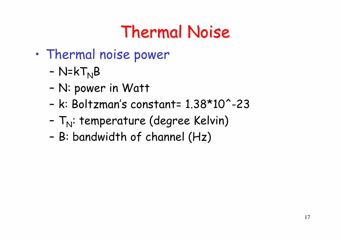
Thermal NoiseThermal Noise• Thermal noise power
– N=kTNB
– N: power in Watt
– k: Boltzman’s constant= 1.38*10^-23
– TN: temperature (degree Kelvin)
– B: bandwidth of channel (Hz)

18
Bit Energy to Noise RatioBit Energy to Noise Ratio• Eb/N0
– Energy per bit over the noise power spectral density
– Related to SNR power ratio
– Independent of bandwidth
19
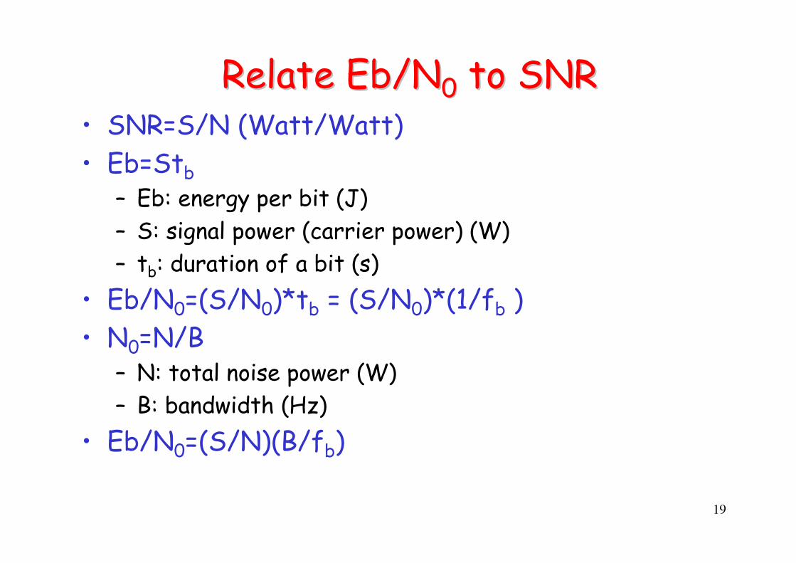
Relate Eb/NRelate Eb/N00 to SNRto SNR• SNR=S/N (Watt/Watt)
• Eb=Stb
– Eb: energy per bit (J)
– S: signal power (carrier power) (W)
– tb: duration of a bit (s)
• Eb/N0=(S/N0)*tb = (S/N0)*(1/fb )
• N0=N/B– N: total noise power (W)
– B: bandwidth (Hz)
• Eb/N0=(S/N)(B/fb)

20
S/N (or Eb/NS/N (or Eb/N00))• To compare systems, generally they should
have the same transmitted S/N (or Eb/N0)
• The S/N (or Eb/N0) at the input to the receiver will determine the system performance
21
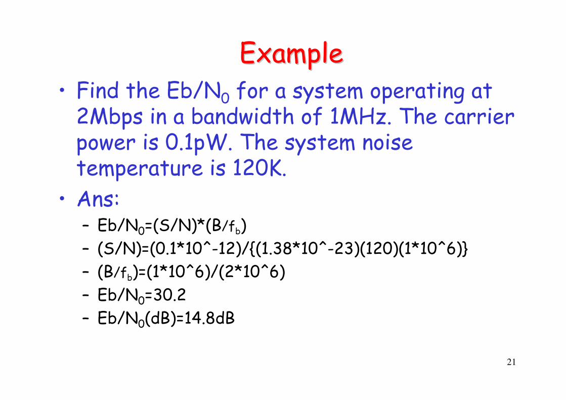
ExampleExample• Find the Eb/N0 for a system operating at
2Mbps in a bandwidth of 1MHz. The carrier power is 0.1pW. The system noise temperature is 120K.
• Ans:– Eb/N0=(S/N)*(B/fb)
– (S/N)=(0.1*10^-12)/{(1.38*10^-23)(120)(1*10^6)}
– (B/fb)=(1*10^6)/(2*10^6)
– Eb/N0=30.2
– Eb/N0(dB)=14.8dB

22
Effective Radiated PowerEffective Radiated Power• Antenna gain
– dBi
– dB gain of an antenna over that of the ideal isotropic unidirectional antenna
• ERP– Effective radiated power from the antenna of
the transmitter
– ERP(dB)=10log(Gant,tx)+10log(Ptx)

23
Effective area of antennaEffective area of antenna• Equivalent area that an antenna can receive
signal energy from an EM wave source
• Relationship to antenna gain– Aeff=(λ2*Gant)/(4π)
– Unit of effective area of antenna: m2
– Gant: antenna gain
– λ: wavelength

24
Signal attenuation in wireless channelSignal attenuation in wireless channel
• Pd=(Ptx*Gant,tx)/(4πr2) (W/m2)– Pd :power density
• Aeff=(λ2*Gant)/(4π) (m2)• Prx= Pd Aeff (W)
– Prx =(Ptx*Gant,tx)/(4πr2) *(λ2*Gant,rx)/(4π)= (PtxGant,txGant,rxλ2)/(16πr2)
• Received power is proportional to (λ2/r2)– Free-space propagation model– Propagation condition depends on
• Wavelength• Distance

25
Signal attenuation in wireless channelSignal attenuation in wireless channel• Wireless channel gain
– Gch=1/Ach=(λ/4πr)2
• Ach: Channel attenuation
– Prx = PtxGant,txGant,rxGch
– Prx(dB)= Ptx(dB)+ Gant,tx(dB) + Gant,rx(dB)+ Gch(dB)
• Define G/T ratio– At receiver – G/T(dB)= Gant,rx(dB)-TN(dB)
• Relationship between antenna gain and system noise temperature
• SNR at receiver– S/N(dB)= Ptx(dB)+ Gant,tx(dB) + Gant,rx(dB)+ Gch(dB)-10log(kTNB)– S/N=S/(N0*B)– S/N0(dB)= Ptx(dB)+ Gant,tx(dB) + Gch(dB)-10log(k) + Gant,rx(dB)-TN(dB)
= Ptx(dB)+ Gant,tx(dB) + Gch(dB)-10log(k) + G/T ratio (dB)

26
ExampleExample• Perform link budget calculation and find
the S/N0 value. (assume free-space propagation)– Antenna pointing loss 1dB– Atmospheric loss 1.5dB– Carrier frequency 4GHz– Transmitting power 40dB– Transmitter antenna gain 12dB– Receiver Gant/TN (antenna gain/thermal noise
temperature) ratio 20dB– Link distance=35000 m

27
AnswerAnswer• S/N0=S/N
• S/N0(dB)=40+12-1-1.5+20-10log(k)-10log(λ2/16πr2)– k= 1.38*10^-23=-228.6(dB)
– λ=(3*10^8)/(4*10^9)=0.075
– 10log(λ2/16πr2)=-135.4 (dB)
• S/N0(dB)=162.7 (dB)

28
Capture modelCapture model• SNRreceived≥SNRthreshold
– Minimum SNR requirement, given a target bit-error-rate (or frame-error-rate)

29
Effective Effective isotropicallyisotropically--radiated power (EIRP) radiated power (EIRP)
• Similar to ERP• EIRP is for isotropic antenna
– Define the size of service area– FCC regulation for unlicensed spectrum– EIRP(dB) = Ptx(dB)-transmission line loss (dB) + antenna
gain (dB)
• FCC Part 15.247 (ISM band regulation)– omni-directional antenna applications in 900MHz and
2.4GHz ISM-band WLAN– Max transmitter power = 1W– Max EIRP = 4W
• To increase additional dB of antenna gain over 6dBi, you need to reduce 1 dB of transmitter power.
30
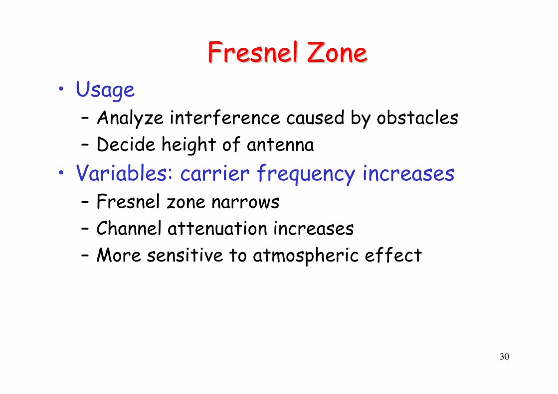
FresnelFresnel ZoneZone• Usage
– Analyze interference caused by obstacles
– Decide height of antenna
• Variables: carrier frequency increases– Fresnel zone narrows
– Channel attenuation increases
– More sensitive to atmospheric effect

31
FresnelFresnel ZoneZone• b=8.65*(2a/f)^0.5
– a in km– f in GHz

32
Other factors Other factors • Rain, snow, fog
• Foliage
• Reflection on building/mountain
• Streets in cities– Radio waves propagate along the streets
– Significant signal attenuation around the corners
• Tunnels– Maximum 60m

33
Computing transmission distanceComputing transmission distance• Given
– minimum SNR requirement• Receiver sensitivity
– Propagation model (path-loss)– Antenna gains– Other loss
• Compute– Maximum transmission range– Required transmission power
• Link budget– Transmission power– Margins for channel variation
• Very important while doing network planning

CrossCross--Layer Design Layer Design Considerations in PHYConsiderations in PHY
35
Summary: Error Compensation Mechanisms
• Cross-layer design and optimization involves with the following error compensation mechanisms– Forward error correction
– Adaptive equalization
– Diversity techniques
• Design selection– System complexity
– Performance metrics

36
Forward Error CorrectionForward Error Correction• Transmitter adds error-correcting bits to data
block– Encoding algorithm adds redundant bits
– Decoding algorithm recovers transmitted information
• Receiver tries to recover the transmitted information from the received bits
• “Possible” to detect/recover error– Detect/correct errors if there are only a limited
number of error bits
– Improve BER (bit-error-rate) performance

37
Spectral efficiencySpectral efficiency• Wireless spectrum is limited resource.
Bandwidth efficiency is an indicator on how well a wireless communication system utilize wireless spectrum.– Bit/sec/Hz

38
Power efficiencyPower efficiency• Most mobile devices are powered by battery
– Electronic technology (CPU, storage) grows much faster than battery technology does
– Affect user experience• Talk-time, standby time• NTT-DoCoMo’s 3G debut trouble
• Multi-layer power efficient design– Not just PHY/MAC– Higher layer considerations
• Always-on? V.S. paging
• Trade-off– Size/weight/battery– Cool features (e.g. large LCD)

39
OutOut--ofof--band radiation and ACIband radiation and ACI• Adjacent-channel interference (ACI)
– Signal cannot be transmitted within “exact” wireless band• Filter design affect the shape of radio waveforms and thus
ACI
• Non-linearity of communication ICs cause additional problems
– Radio signal energy outside main lobe creates interference to others.
• Consider both ACI and co-channel interference on system performance evaluation– ACI might implicitly (unexpectedly) affect system
performance

40
Example of ACIExample of ACI• My experience with 802.11b testbed
– 2.4GHz ISM bands
– Total 11 channels (3 non-overlap channels: 1,6,11)
– In reality, non-overlapping channels still interfere with each other
– 1 network node with 2 802.11b interface cards. Due to ACI, two cards need to be separated with 1m wire.

41
Resilience to multiResilience to multi--path fadingpath fading• Different modulation and coding scheme
perform differently under multi-path fading– You learn modulation performance in AWGN
(Additive White Gaussian Noise) channel in communication courses
– Modulation and coding performance in fading channel should also be considered
• Many wireless communications design are to overcome multi-path fading

42
Constant Envelope ModulationConstant Envelope Modulation• Non-linearity in power amplifier result in
poor performance of non-constant envelope modulation
• Trade-off between spectral efficiency and constant-envelope property
CrossCross--Layer Design with Layer Design with Diversity TechniquesDiversity Techniques

44
Overview of diversity techniquesOverview of diversity techniques• Exploit several communication possibilities
and enhance system performance through diversification
• Multi-path fading– Multi-path effect create multiple copies of
signals– Fading could occur at different moments– Apply diversity techniques to alleviate effects
of multi-path fading
• Not just avoid fading but utilize fading to improve performance

45
Several types of diversity techniquesSeveral types of diversity techniques
• Time diversity• Frequency diversity• Space diversity• Extend diversity concept to different
places (not just PHY)– Conventionally, diversity techniques are applied
to improve PHY layer signal reception– Recently, diversity concept is applied to higher
protocol layers to improve system performance• Macro-diversity• Network diversity

46
Time diversityTime diversity• RAKE receiver
– Multiple “fingers” at the receiver– Receive multiple copies of signals– Commonly applied in CDMA systems (e.g. IS-95)
• Equalization– Adaptively estimate the channel characteristics– “Reverse” the channel effect and eliminate ISI– Examples
• MLSE(maximum likelihood sequence estimate) Equalizer
– Viterbi algorithm
• Decision feedback equalization (DFE)

47
Upon receiving multiple copies of signalsUpon receiving multiple copies of signals• Signal processing techniques for received radio signals
– Select the best signal• Simple but not the optimal solution
– Combine multiple copies• Several combining algorithm• sum everything linearly (linear combining )• Weighted sum (e.g. maximal-ratio combining)
• Communications basics– What do you know? (a priori knowledge)– Estimate your answer
• Based on what you received to guess what is transmitted• Conditional probability
– Trade-off between performance and implementation complexity• Circuits• Power consumption• Robustness to imperfect conditions (non-linearity in amplifier)• $$$
48
Frequency diversityFrequency diversity• Fading could be frequency-selective
• Frequency hopping is one commonly used frequency diversity technique– GSM
– 802.11 FHSS
– Bluetooth

49
Space diversity/Antenna diversitySpace diversity/Antenna diversity• Smart antenna
– Very promising technique to enhance system capacity “significantly”
• Several possibilities– Multiple antennas at different location
– Multiple antennas with different polarization at the same location (polarization diversity)
– Sectored antenna with different angles of arrival (angle diversity)
– Adaptive beam forming • Change antenna pattern adaptively
• Steering antenna (with a motor) to point to different directions

50
MIMOMIMO• Multiple-input multiple-output (MIMO)
– Multiple tx antennas and multiple rx antennas
– Channel capacity increases with the number of antennas
– Form multiple “virtual channels” among antenna pairs• Radio model (correlation among virtual channels) matters
– Space-time signal processing (coding)
• 2 types– Increase data rate
– Increase robustness (lower error rate)
• MIMO is the key technology among recent wireless advancements

51
Network diversityNetwork diversity• Seek better communications among
– Multiple interfaces
– Multiple routes
– Multiple access points (or base stations)
• “Opportunistic” wireless networking design
WWAN BS
Poor WWAN link
Good
WWAN link
WLAN
Dual-mode
Relay GatewayMobile NodeBS
AP
AP
Some examples:


