Lecture -3 Flexure Load Only
41
Department of Civil Engineering, N-W.F.P. University of Engineering and Technology Peshawar Lecture-03 Lecture 03 Design of RC members for Flexure and Axial Loads By: Prof Dr. Qaisar Ali Civil Engineering Department Civil Engineering Department NWFP UET Peshawar drqaisarali@nwfpuet edu pk Prof. Dr. Qaisar Ali CE 5115 Advance Design of Reinforced Concrete Structures 1 drqaisarali@nwfpuet.edu.pk
-
Upload
abdul-hamid-bhatti -
Category
Documents
-
view
42 -
download
0
description
rccbook
Transcript of Lecture -3 Flexure Load Only

Department of Civil Engineering, N-W.F.P. University of Engineering and Technology Peshawar
Lecture-03Lecture 03Design of RC members for Flexure and Axial Loads
By: Prof Dr. Qaisar Ali
Civil Engineering DepartmentCivil Engineering Department
NWFP UET Peshawardrqaisarali@nwfpuet edu pk
Prof. Dr. Qaisar Ali CE 5115 Advance Design of Reinforced Concrete Structures 1
Department of Civil Engineering, N-W.F.P. University of Engineering and Technology Peshawar
Topics AddressedTopics AddressedBehavior of Homogenous Members Subjected toFlexure Load only
Reinforced Concrete Members subjected to FlexureReinforced Concrete Members subjected to FlexureLoad only
Si l i f d (t i l i f t) t lSingly reinforced (tension only reinforcement) rectangularmembers
BehaviorBehavior
Flexural capacity
Ductility Requirement
Prof. Dr. Qaisar Ali
Ductility Requirement
2

Department of Civil Engineering, N-W.F.P. University of Engineering and Technology Peshawar
Topics AddressedTopics AddressedDoubly reinforced (tension and compression reinforcement)rectangular members
Flexural capacity
Ductility Requirement
T and Hollow members
Flexural capacity
Ductility Requirement
Prof. Dr. Qaisar Ali 3

Department of Civil Engineering, N-W.F.P. University of Engineering and Technology Peshawar
Behavior of Homogenous Members gSubjected to Flexure Load only
BehaviorElastic and inelastic stress
R (radius of curvature)Compression
f2
f
inelastic stress distribution in homogeneous members
N.A(zero stress line)
P
f1
fp
εmembers subjected to flexure load only
Tension ∆
fp
−εpε1 εp ε2
h
ε < εmax f < fmax
1fp
ε1
p
f = MyI Linear
Proportionality f = 7 5 f '
ε
only fp
b
p y
h
ε > εmax f > fmax
2f
p
ε2
p
f = 7.5 f
Non-linearProportionality
εp
max c
Prof. Dr. Qaisar Ali 4
b
Proportionalitypf

Department of Civil Engineering, N-W.F.P. University of Engineering and Technology Peshawar
RC members subjected to
B h i
RC members subjected to flexure load only
Behavior
Three stages before collapse
Un-cracked Concrete – Elastic Stage
Cracked Concrete (tension zone) – Elastic Stage
Cracked Concrete (tension zone) – Inelastic (UltimateStrength) Stage
Prof. Dr. Qaisar Ali 5
Department of Civil Engineering, N-W.F.P. University of Engineering and Technology Peshawar
RC members subjected to RC members subjected to flexure load only
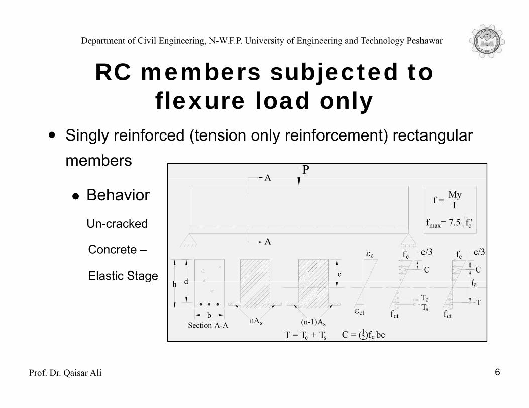
Singly reinforced (tension only reinforcement) rectangular members
AP
Behavior
Un-cracked
A
f = MyI
f = 7.5 f 'max c
Concrete –
Elastic Stage
A
dh c
εc fc
Cl
c/3 fc
C
c/3
g dh
bnAs (n-1)As
εct ctf
la
Section A-A
TsTc
ctfT
T T + T C (1)f b
Prof. Dr. Qaisar Ali 6
T = T + Tc s C = (12)f bcc

Department of Civil Engineering, N-W.F.P. University of Engineering and Technology Peshawar
RC members subjected to jflexure load only
Singly reinforced (tension only reinforcement) rectangularmembers
Behavior
Un-cracked Concrete – Elastic Stageg
Stresses are computed as in case of homogeneous elastic concretebeam.
f = My/ I (with fmax = 7.5√fc′)
Prof. Dr. Qaisar Ali 7
Department of Civil Engineering, N-W.F.P. University of Engineering and Technology Peshawar
RC members subjected to jflexure load only
Singly reinforced (tension only reinforcement)Singly reinforced (tension only reinforcement)rectangular members
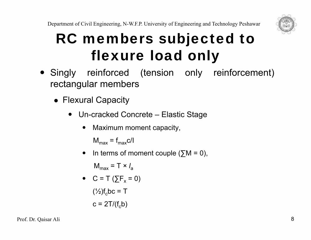
Flexural CapacityUn-cracked Concrete – Elastic Stage
Maximum moment capacity,
Mmax = fmaxc/I
In terms of moment couple (∑M = 0),
M = T × lMmax = T × laC = T (∑Fx = 0)
(½)fcbc = T
Prof. Dr. Qaisar Ali
c = 2T/(fcb)
8

Department of Civil Engineering, N-W.F.P. University of Engineering and Technology Peshawar
RC members subjected to jflexure load only
Singly reinforced (tension only reinforcement)Singly reinforced (tension only reinforcement) rectangular members A P
Behavior
Cracked A
Concrete –
(Tension Zone)
A
c
fc
Cl
c/3
dElastic Stage
dh
b nAs
T = A fs
l
S ti A A
d
s
a
Prof. Dr. Qaisar Ali 9
Section A-A
T = A fs s C = (12)f bcc l = (d - c/3)a

Department of Civil Engineering, N-W.F.P. University of Engineering and Technology Peshawar
RC members subjected to jflexure load only
Singly reinforced (tension only reinforcement)Singly reinforced (tension only reinforcement) rectangular members
Flexural Capacityp yCracked Concrete (tension zone) – Elastic Stage
In terms of moment couple (∑M = 0)
M = Tla = Asfs (d – c/3)
As = M/fs(d – c/3)
C T (∑F 0)C = T (∑Fx = 0)
(½)fcbc = Asfsc = 2Asfs/fcb {where fs = nfc and n =Es/Ec}
Prof. Dr. Qaisar Ali
s s c { s c s c}
10
Department of Civil Engineering, N-W.F.P. University of Engineering and Technology Peshawar
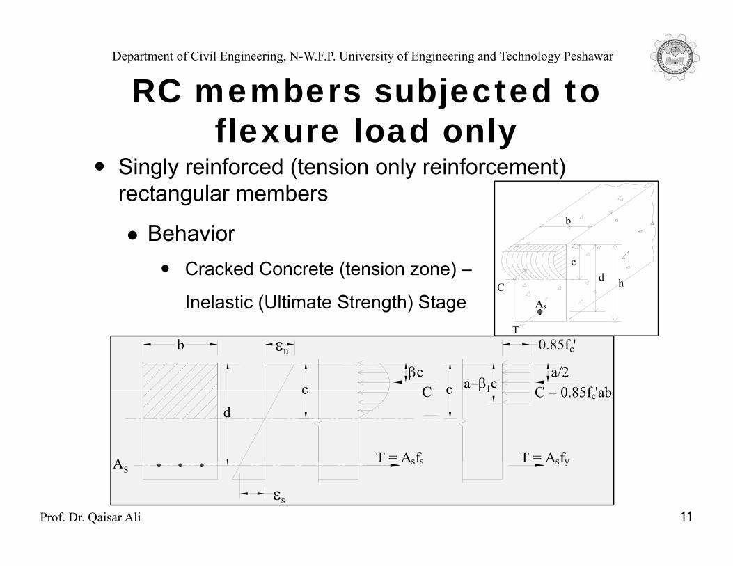
RC members subjected to jflexure load only
Singly reinforced (tension only reinforcement) g y ( y )rectangular members
Behaviorb
Cracked Concrete (tension zone) –
Inelastic (Ultimate Strength) Stage
cd hC
As
Tb εu
c a=β c1
c0.85f '
ca/2
C 0 85f 'abβc
Cd
A
c β1
T = A fs y
c
T = A fs s
C = 0.85f 'abcC
Prof. Dr. Qaisar Ali 11εs
AsT A fs yT A fs s
Department of Civil Engineering, N-W.F.P. University of Engineering and Technology Peshawar
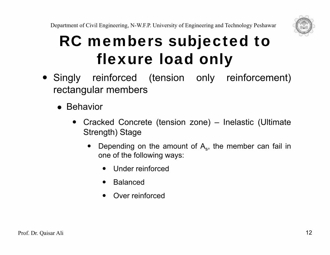
RC members subjected to jflexure load only
Singly reinforced (tension only reinforcement)Singly reinforced (tension only reinforcement)rectangular members
BehaviorCracked Concrete (tension zone) – Inelastic (UltimateStrength) Stage
D di th t f A th b f il iDepending on the amount of As, the member can fail inone of the following ways:
Under reinforced
Balanced
Over reinforced
Prof. Dr. Qaisar Ali 12
Department of Civil Engineering, N-W.F.P. University of Engineering and Technology Peshawar
RC members subjected to jflexure load only
Singly reinforced (tension only reinforcement)Singly reinforced (tension only reinforcement)rectangular members
B h iBehavior
Cracked Concrete (tension zone) – Inelastic (UltimateSt th) StStrength) Stage
Under reinforced: Steel yields before concrete crushes
Prof. Dr. Qaisar Ali 13

Department of Civil Engineering, N-W.F.P. University of Engineering and Technology Peshawar
RC members subjected to jflexure load only
Singly reinforced (tension only reinforcement)Singly reinforced (tension only reinforcement)rectangular members
BehaviorBehavior
Cracked Concrete (tension zone) – Inelastic (UltimateStrength) StageStrength) Stage
Balanced: Crushing of concrete and yielding of steeloccurs simultaneously.occurs simultaneously.
Prof. Dr. Qaisar Ali 14

Department of Civil Engineering, N-W.F.P. University of Engineering and Technology Peshawar
RC members subjected to jflexure load only
Singly reinforced (tension only reinforcement)Singly reinforced (tension only reinforcement)rectangular members
BehaviorBehavior
Cracked Concrete (tension zone) – Inelastic (UltimateStrength) StageStrength) Stage
Over reinforced: Concrete crushes before steel yields
Prof. Dr. Qaisar Ali 15

Department of Civil Engineering, N-W.F.P. University of Engineering and Technology Peshawar
RC members subjected to jflexure load only
Flexural Capacity of RC members subjected toflexure load only
The ACI Code
Design Assumptions of the ACI code for design ofDesign Assumptions of the ACI code for design ofmembers subject to flexure or axial loads or to combinedflexure and axial loads.
Prof. Dr. Qaisar Ali 16

Department of Civil Engineering, N-W.F.P. University of Engineering and Technology Peshawar
RC members subjected to jflexure load only
Flexural Capacity of RC members subjected toflexure load only
The ACI Code
The Flexural Strength: ACI R10 3 3 The nominalThe Flexural Strength: ACI R10.3.3 — The nominalflexural strength of a member is reached when the strainin the extreme compression fiber reaches the assumedstrain limit 0.003.
Prof. Dr. Qaisar Ali 17

Department of Civil Engineering, N-W.F.P. University of Engineering and Technology Peshawar
RC members subjected to jflexure load only
Singly reinforced (tension only reinforcement)g y ( y )rectangular members
Flexural Capacityp y
Mn = Asfy (d – a/2) [Nominal capacity]
ΦMn = ΦAsfy(d – a/2) [Ultimate capacity]n s y
a = Asfy/0.85fc′b
b εu c0.85f '
dc a=β c1c
a/2C = 0.85f 'abc
βcC
Prof. Dr. Qaisar Ali 18εs
AsT = A fs yT = A fs s

Department of Civil Engineering, N-W.F.P. University of Engineering and Technology Peshawar
RC members subjected to jflexure load only
Singly reinforced (tension only reinforcement)Singly reinforced (tension only reinforcement)rectangular members
D tilit R i tDuctility Requirements
In codes prior to 2002, maximum reinforcement requirement usedto be ensured by maximum reinforcement ratio ρ = 0 75ρbto be ensured by maximum reinforcement ratio ρmax 0.75ρb.
ρb = 0.85 β1(fc′/fy) εu/ (εu + εy) b εu
cd
A
c
Prof. Dr. Qaisar Ali 19εs
As

Department of Civil Engineering, N-W.F.P. University of Engineering and Technology Peshawar
RC members subjected to jflexure load only
Singly reinforced (tension only reinforcement)Singly reinforced (tension only reinforcement)rectangular members
D tilit R i tDuctility Requirements
However ACI 318-02 replaces εy by the net strain (εt) intension steel and ρ by ρ Transition zone TensionCompressiontension steel and ρb by ρmax.
ρmax = 0.85 β1(fc′/fy) εu/ (εu + εt)
{3√ (f ′)/f } ≥ 200/f
Transition zone Tensioncontrolled
Compression controlled
φ = 0.90
φ = 0.567 + 66.7ε t
Spiral
ρmin = {3√ (fc′)/fy} ≥ 200/fy
φ = 0.70
φ = 0.65
φ = 0.483 + 83.3ε t
Other
Prof. Dr. Qaisar Ali 20
ε = 0.002t ε = 0.005t
Net tensile strain
Department of Civil Engineering, N-W.F.P. University of Engineering and Technology Peshawar
RC members subjected to jflexure load only
Singly reinforced (tension only reinforcement)Singly reinforced (tension only reinforcement)rectangular members
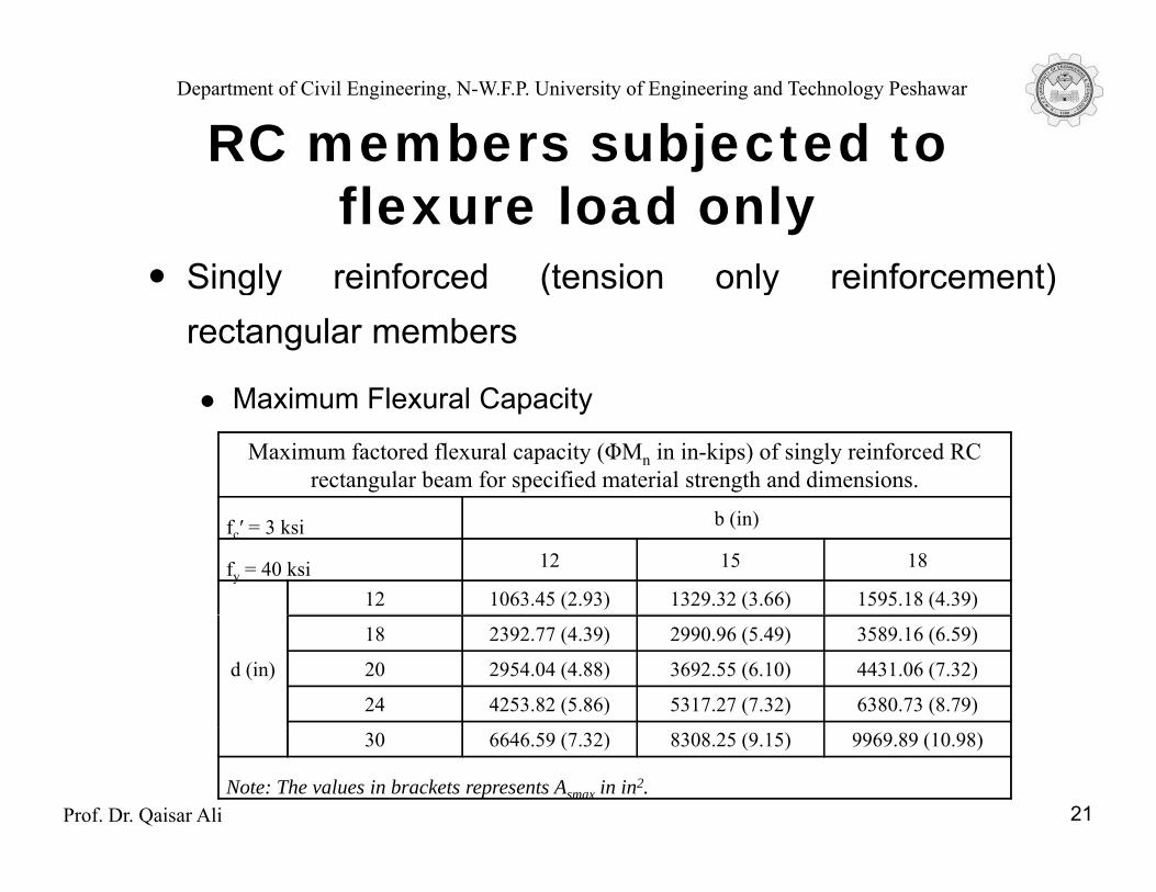
M i Fl l C itMaximum Flexural Capacity
Maximum factored flexural capacity (ΦMn in in-kips) of singly reinforced RC rectangular beam for specified material strength and dimensions.
fc′ = 3 ksi b (in)
fy = 40 ksi 12 15 18
12 1063.45 (2.93) 1329.32 (3.66) 1595.18 (4.39)
d (in)
18 2392.77 (4.39) 2990.96 (5.49) 3589.16 (6.59)
20 2954.04 (4.88) 3692.55 (6.10) 4431.06 (7.32)
24 4253.82 (5.86) 5317.27 (7.32) 6380.73 (8.79)
Prof. Dr. Qaisar Ali 21
30 6646.59 (7.32) 8308.25 (9.15) 9969.89 (10.98)
Note: The values in brackets represents Asmax in in2.
Department of Civil Engineering, N-W.F.P. University of Engineering and Technology Peshawar
RC members subjected to jflexure load only
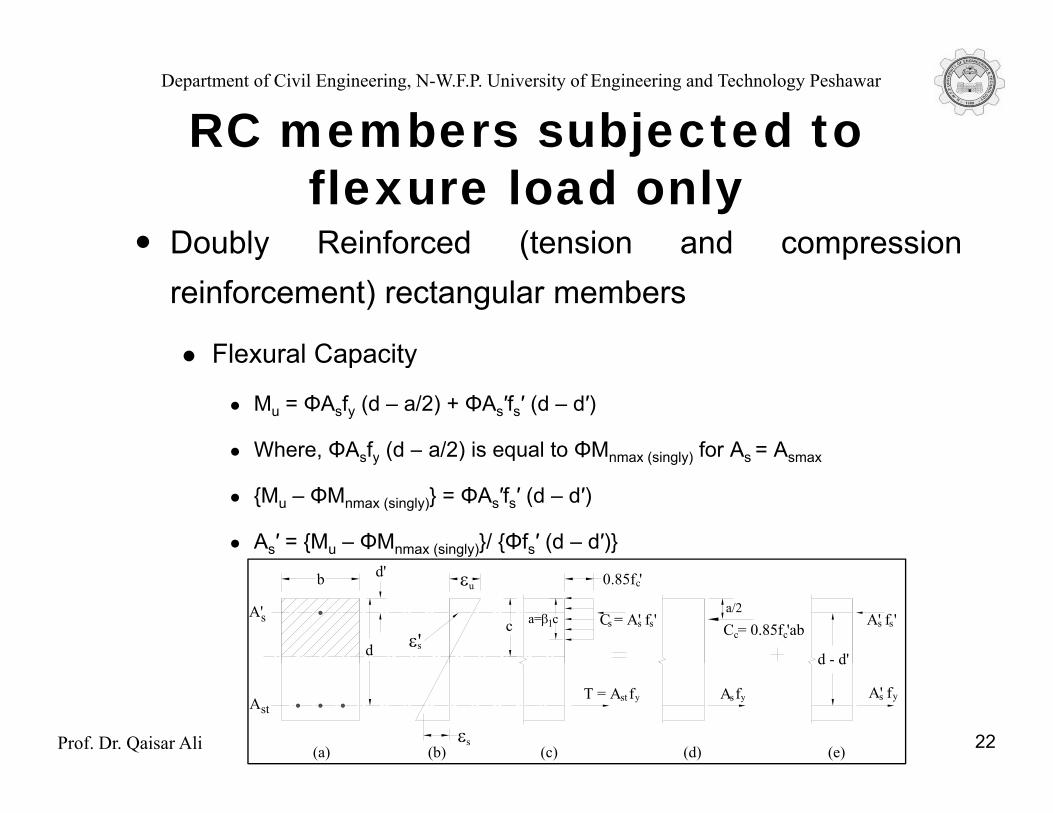
Doubly Reinforced (tension and compressionDoubly Reinforced (tension and compressionreinforcement) rectangular members
Flexural CapacityFlexural Capacity
Mu = ΦAsfy (d – a/2) + ΦAs′fs′ (d – d′)
Where, ΦAsfy (d – a/2) is equal to ΦMnmax (singly) for As = Asmax, s y ( ) q nmax (singly) s smax
{Mu – ΦMnmax (singly)} = ΦAs′fs′ (d – d′)
As′ = {Mu – ΦMnmax (singly)}/ {Φfs′ (d – d′)}
b εu
sε'd
d'
A's c a=β c1
0.85f 'c
C = A' f 's
d - d'
s A' f 's sa/2
C = 0.85f 'abccs
Prof. Dr. Qaisar Ali 22εs
AstT = A fst
d d
A fys
(a) (b) (c) (e)(d)
y A' fys

Department of Civil Engineering, N-W.F.P. University of Engineering and Technology Peshawar
RC members subjected to jflexure load only
Doubly Reinforced (tension and compressionDoubly Reinforced (tension and compressionreinforcement) rectangular members
Ductility RequirementsDuctility RequirementsCc + Cs = T [ ∑Fx = 0 ]
0.85fc′ab + As′fs′ = AstfyWhere,
Cc = Compression force due to concrete in compression region,
Cs = Compression force in steel in compression region needed to balance the t i f i dditi t th t i f id d b Atension force in addition to the tension force provided by Asmax (singly).
For amax = β1c = 0.85 × 0.375d, 0.85fc′ab is equal to Asmax (singly)fyAsmax (singly)fy + As′fs′ = Astfy
Prof. Dr. Qaisar Ali
(Ast – As′fs′/fy) = Asmax (singly) (Ast – As′fs′/fy) ≤ Asmax (singly)
23

Department of Civil Engineering, N-W.F.P. University of Engineering and Technology Peshawar
RC members subjected to jflexure load only
Doubly Reinforced (tension and compressionDoubly Reinforced (tension and compressionreinforcement) rectangular members
Ductility RequirementsDuctility Requirements
The ratios (d′/d) and minimum beam effective depths (d) for compressionreinforcement to yield
Minimum beam depths for compression reinforcement to yield
εt = 0.005t
fy, psi Maximum d'/d Minimum d for d' = 2.5" (in.)
40000 0.2 12.3
60000 0 12 21 5
Prof. Dr. Qaisar Ali 24
60000 0.12 21.5
75000 0.05 48.8

Department of Civil Engineering, N-W.F.P. University of Engineering and Technology Peshawar
RC members subjected to jflexure load only
T-BeamsT-Beams
Flexural Capacity
bεu 0.85f 'c0.85f '
/2 h /2f
(b-b )/2w
dc a=β c1
a/2
T A f
C = 0.85f 'abc w
hfh /2
f
C = 0.85f '(b - b )hc w f
f
1 2
xC
εs
AstT = A fst
(a)
y
bw
T = A fs y T = A fysf
(b) (c) (d) (e)
1 2
Prof. Dr. Qaisar Ali 25
Department of Civil Engineering, N-W.F.P. University of Engineering and Technology Peshawar
RC members subjected to jflexure load only
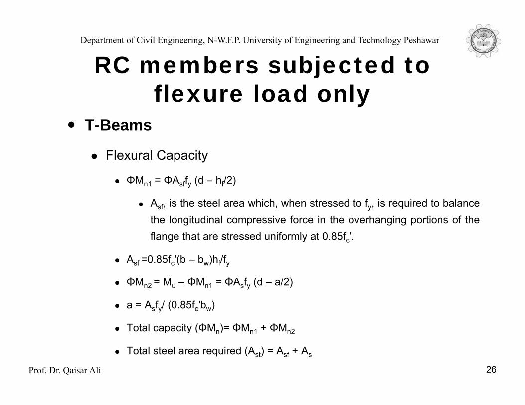
T-BeamsT-Beams
Flexural Capacity
ΦM ΦA f (d h /2)ΦMn1 = ΦAsffy (d – hf/2)
Asf, is the steel area which, when stressed to fy, is required to balancethe longitudinal compressive force in the overhanging portions of theflange that are stressed uniformly at 0.85fc′.
Asf =0.85fc′(b – bw)hf/fy
ΦM M ΦM ΦA f (d /2)ΦMn2 = Mu – ΦMn1 = ΦAsfy (d – a/2)
a = Asfy/ (0.85fc′bw)
Total capacity (ΦMn)= ΦMn1 + ΦMn2
Prof. Dr. Qaisar Ali
Total capacity (ΦMn) ΦMn1 ΦMn2
Total steel area required (Ast) = Asf + As
26

Department of Civil Engineering, N-W.F.P. University of Engineering and Technology Peshawar
RC members subjected to jflexure load only
T BeamsT-Beams
Flexural Capacity (Alternate Formulae)
ΦMn = Mu= ΦAstfy (d – x)
Ast = Mu/ {Φfy (d – x)}
a = {A f – 0 85f ′ (b – b )h }/0 85f ′ba = {Astfy – 0.85fc (b – bw)hf}/0.85fc bw
bεu 0.85f 'c0.85f '
h x
(b-b )/2w
d
A
c a=β c1
T = A fst y
hfxC
Prof. Dr. Qaisar Ali 27
εs
AstT A fst
(a)
y
bw
(b) (c)
Department of Civil Engineering, N-W.F.P. University of Engineering and Technology Peshawar
RC members subjected to jflexure load only
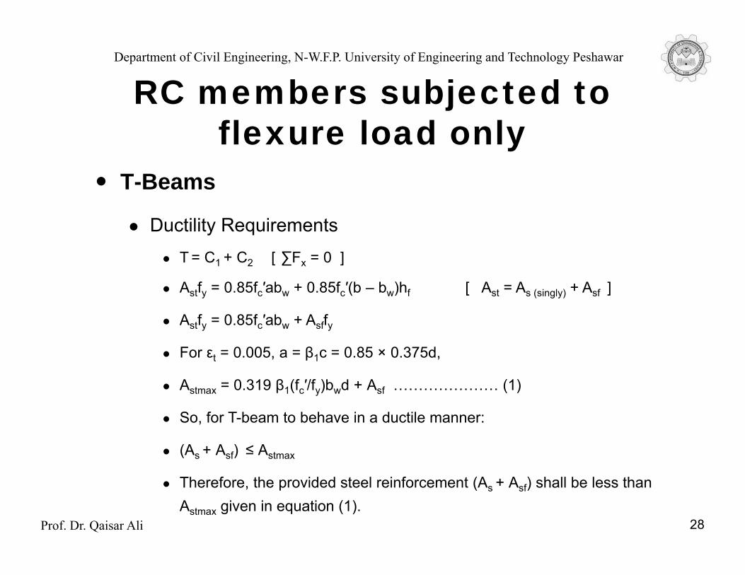
T BeamsT-Beams
Ductility RequirementsT = C1 + C2 [ ∑Fx = 0 ]
Astfy = 0.85fc′abw + 0.85fc′(b – bw)hf [ Ast = As (singly) + Asf ]
Astfy = 0.85fc′abw + AsffyAstfy 0.85fc abw Asffy
For εt = 0.005, a = β1c = 0.85 × 0.375d,
Astmax = 0.319 β1(fc′/fy)bwd + Asf ………………… (1)
So, for T-beam to behave in a ductile manner:
(As + Asf) ≤ Astmax
Prof. Dr. Qaisar Ali
Therefore, the provided steel reinforcement (As + Asf) shall be less than Astmax given in equation (1).
28
Department of Civil Engineering, N-W.F.P. University of Engineering and Technology Peshawar
RC members subjected to jflexure load only
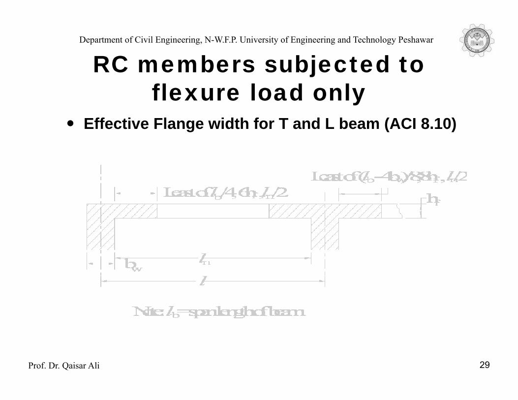
Effective Flange width for T and L beam (ACI 8 10)Effective Flange width for T and L beam (ACI 8.10)
Prof. Dr. Qaisar Ali 29
Department of Civil Engineering, N-W.F.P. University of Engineering and Technology Peshawar
RC members subjected to jflexure load only
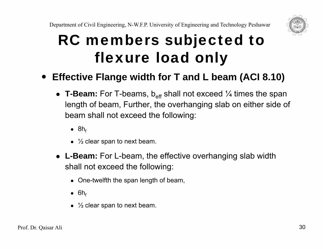
Effective Flange width for T and L beam (ACI 8 10)Effective Flange width for T and L beam (ACI 8.10)T-Beam: For T-beams, beff shall not exceed ¼ times the span length of beam, Further, the overhanging slab on either side of g g gbeam shall not exceed the following:
8hf
½ clear span to next beam½ clear span to next beam.
L-Beam: For L-beam, the effective overhanging slab width shall not exceed the following:
One-twelfth the span length of beam,
6hf
½ l t t b
Prof. Dr. Qaisar Ali
½ clear span to next beam.
30
Department of Civil Engineering, N-W.F.P. University of Engineering and Technology Peshawar
RC members subjected to jflexure load only
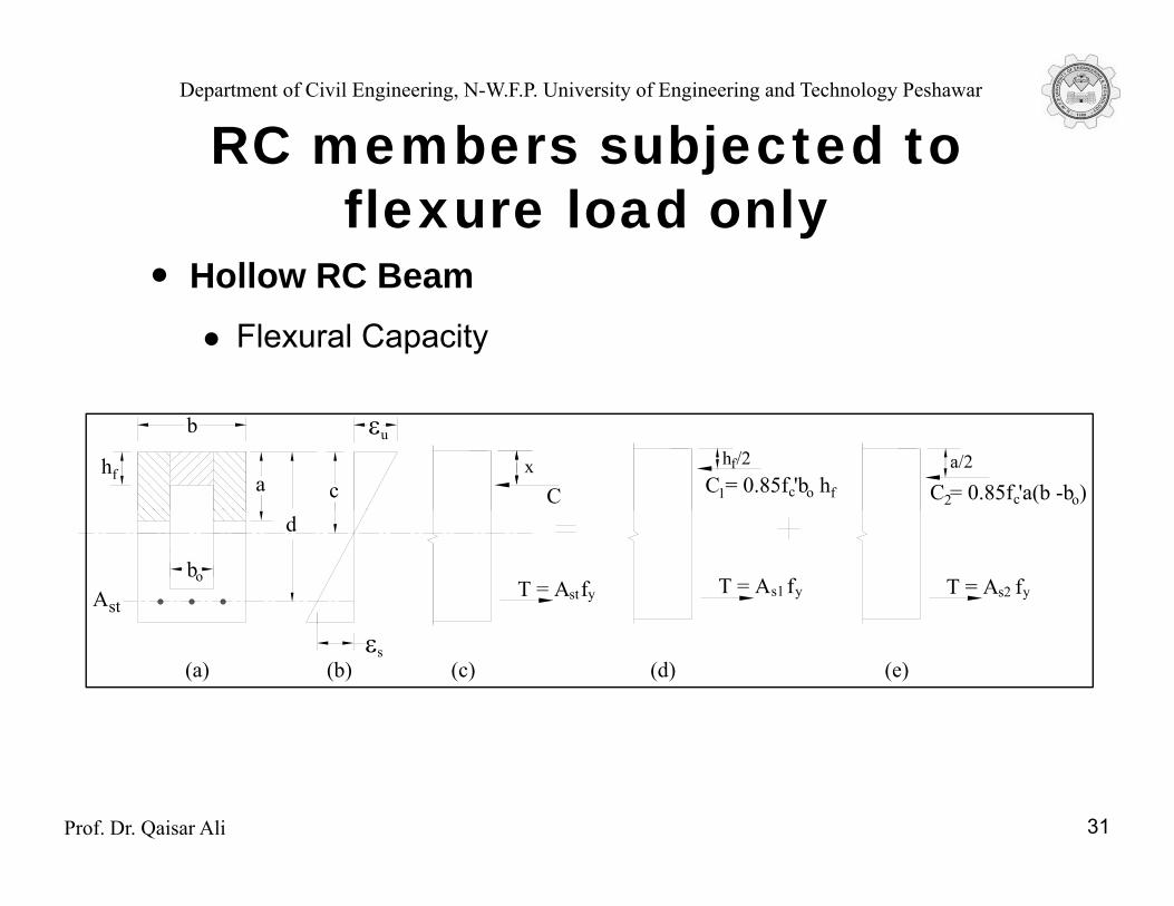
Hollow RC BeamHollow RC BeamFlexural Capacity
b εu
ca/2
C = 0.85f 'a(b -b )c o
h /2C = 0.85f 'b hc o f
fhf
21Cax
d
AstT = A fst y
bo T = A fs2 yT = A fys1
εs(a) (b) (c) (d) (e)
Prof. Dr. Qaisar Ali 31

Department of Civil Engineering, N-W.F.P. University of Engineering and Technology Peshawar
RC members subjected to jflexure load only
Hollow RC BeamHollow RC BeamFlexural Capacity
ΦMn1 = ΦAs1fy (d – hf/2)n1 s1 y ( f )Asf, is the steel area which, when stressed to fy, is required to balance thelongitudinal compressive force in the overhanging portions of the flangethat are stressed uniformly at 0.85fc′.
As1 =0.85fc′bohf/fyΦMn2 = Mu – ΦMn1 = ΦAs2fy (d – a/2)
a = As2fy/ {0.85fc′(b - bo)}
Total capacity (ΦMn)= ΦMn1 + ΦMn2
T t l t l i d (A ) A A
Prof. Dr. Qaisar Ali
Total steel area required (Ast) = As1 + As2
32

Department of Civil Engineering, N-W.F.P. University of Engineering and Technology Peshawar
RC members subjected to jflexure load only
Hollow RC BeamHollow RC Beam
Flexural Capacity (Alternate Formulae)
ΦM = M = ΦA f (d x)ΦMn = Mu = ΦAstfy (d – x)
Ast = Mu/ {Φfy (d – x)}
x = {bohf2/2 + (b – bo)a2/2}/ {(b –bo)a + bohf}{ o f ( o) } {( o) o f}
a = {Astfy – 0.85fc′bohf}/0.85fc′(b –bo)b εu
h
dc
bo
hf
Cax
Prof. Dr. Qaisar Ali 33εs
AstT = A fst y
bo
(a) (b) (c)
Department of Civil Engineering, N-W.F.P. University of Engineering and Technology Peshawar
RC members subjected to jflexure load only
Hollow RC Beam b εuHollow RC Beam
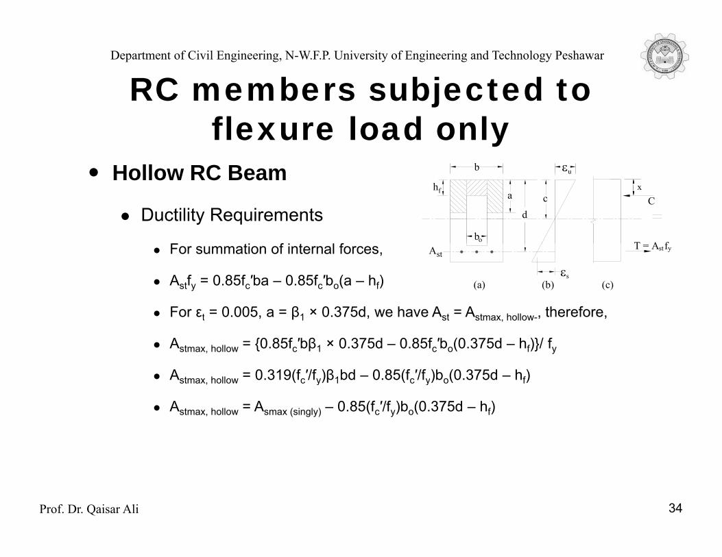
Ductility Requirements
F i f i l f
u
dc
T A fbo
hf
Cax
For summation of internal forces,
Astfy = 0.85fc′ba – 0.85fc′bo(a – hf)
For εt = 0 005 a = β1 × 0 375d we have A t = A t h ll therefore
εs
AstT = A fst y
(a) (b) (c)
For εt = 0.005, a = β1 × 0.375d, we have Ast = Astmax, hollow-, therefore,
Astmax, hollow = {0.85fc′bβ1 × 0.375d – 0.85fc′bo(0.375d – hf)}/ fy
Astmax, hollow = 0.319(fc′/fy)β1bd – 0.85(fc′/fy)bo(0.375d – hf), y y
Astmax, hollow = Asmax (singly) – 0.85(fc′/fy)bo(0.375d – hf)
Prof. Dr. Qaisar Ali 34

Department of Civil Engineering, N-W.F.P. University of Engineering and Technology Peshawar
1 Un-cracked Concrete Stage1. Un-cracked Concrete Stage
ft < frM < MCompression zone M < Mcrfc = ft << fc'
h d
b
Tension Zone
Strain Diagram
Stress Diagram
Compressive Stress
fc'e s o o e
ft = fr = 7.5 √fc'
fc
ft = fc
Prof. Dr. Qaisar Ali
Tensile Stress
t r √ c
Stress-Strain Diagram for Concrete

Department of Civil Engineering, N-W.F.P. University of Engineering and Technology Peshawar
C=0.5fc x (b x0.5h)
fc
c ( )
1/2 h
M
2/3 h
1/2 h
T=0.5ft x (b x0.5h)
bft
Stress diagram
C=T ; fc = ftM = 0.5fc x (b x 0.5h) x (2/3 h)
= 1/6 f x b x h2fc = ft = Mc/Igwhere c = 0 5hOR= 1/6 fc x b x h2
fc = ft = 6M/(bh2)
where c = 0.5hIg = bh3/12
OR
At ft = fr , where modulus of rupture, fr = 7.5 √fc’C ki M t C it M f I /(0 5h) (f b h2)/6
Prof. Dr. Qaisar Ali
Cracking Moment Capacity, Mcr = fr x Ig/(0.5h) = (fr x b x h2)/6
Department of Civil Engineering, N-W.F.P. University of Engineering and Technology Peshawar
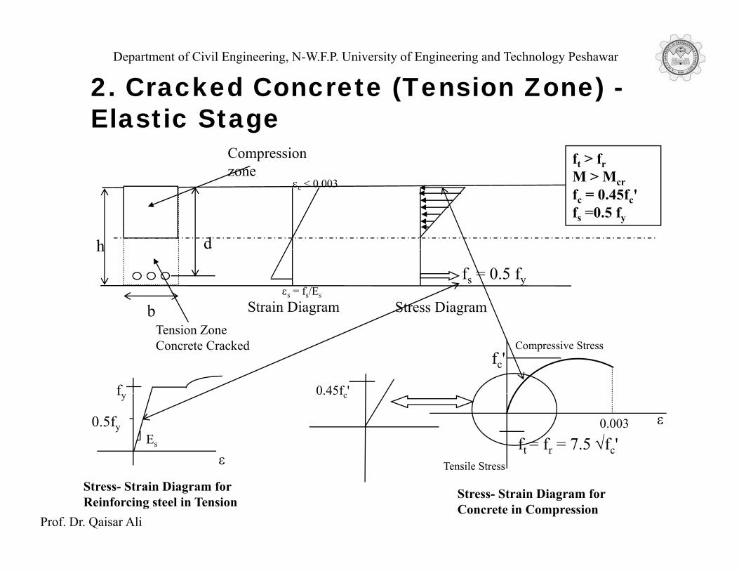
2. Cracked Concrete (Tension Zone) -Elastic Stage
Compression zone
ft > frM > Mεc < 0.003
h d
M > Mcrfc = 0.45fc'fs =0.5 fy
εs = fs/Es
h
b Strain Diagram Stress Diagram
fs = 0.5 fy
f 0.45f '
Tension Zone Concrete Cracked Compressive Stress
fc'
ε
fy
0.5fy
0.45fc
Tensile Stress
ft = fr = 7.5 √fc'ε
Es
0.003
Prof. Dr. Qaisar Ali
Tensile Stress
Stress- Strain Diagram for Concrete in Compression
Stress- Strain Diagram for Reinforcing steel in Tension

Department of Civil Engineering, N-W.F.P. University of Engineering and Technology Peshawar
C=0.5fc × (bc)
fc
c ( )
1/2 h c
la = d – c/31/2 h
M
d
T= Asfs
b Stress diagram
In terms of moment couple (∑M = 0)M = Tla = Asfs (d – c/3)A M/f (d /3)As = M/fs(d – c/3)
C = T (∑Fx = 0)
Prof. Dr. Qaisar Ali
(½)fcbc = Asfs
c = 2Asfs/fcb {where fs = nfc and n =Es/Ec}

Department of Civil Engineering, N-W.F.P. University of Engineering and Technology Peshawar
3. Cracked Concrete (Tension Zone) -( )Ultimate Strength Stage
ft > >frM > >Mcr
Compression zone
ε = 0 003 crfs = fyfc = entire stress block until compression f ilh d
εc = 0.003
failureh
b
d
Strain Diagram Stress Diagram Compressive Stress
T = Asfyεs = fy/Es
bTension Zone Concrete Cracked
g Compressive Stress
fc'fy
E
εStress-Strain Diagram for Concrete in Compression
Stress-Strain Diagram for Reinforcing Steel in Tension
Es0.003 ε
Prof. Dr. Qaisar AliDr.
Qaisar Ali
p
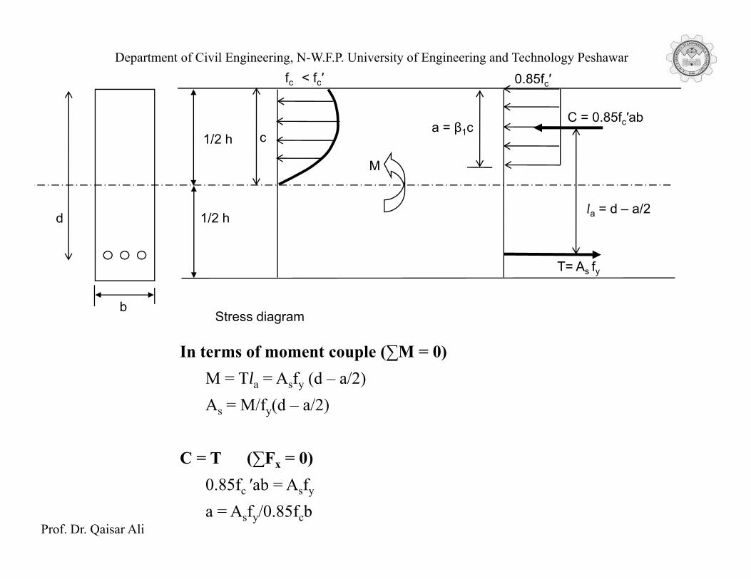
Department of Civil Engineering, N-W.F.P. University of Engineering and Technology Peshawarfc < fc′ 0.85fc′
C = 0.85fc′ab 1/2 h
M
ca = β1c
la = d – a/21/2 hd
T= As fy
bStress diagram
In terms of moment couple (∑M = 0)M = Tla = Asfy (d – a/2)A M/f (d /2)As = M/fy(d – a/2)
C = T (∑Fx = 0)
Prof. Dr. Qaisar Ali
0.85fc ′ab = Asfy
a = Asfy/0.85fcb

Department of Civil Engineering, N-W.F.P. University of Engineering and Technology Peshawar
Typical Stress Strain Curves for Concrete Typical Stress-Strain Curves for Concrete and Reinforcing Steel
Prof. Dr. Qaisar AliDr.
Qaisar Ali