Advanced Aerodynamic Analysis of the NASA High-Lift Trap ...
description

AERODYNAMIC LIFT-TYPE WIND ENERGY TECHNOLOGY
Part B Module 1 – Wind Energy
SAILING ACROSS THE WIND
• Boat speed added to true wind
• Apparent wind exceeds true wind
• Boat speed can exceed wind speed Apparent wind
True wind
Boat speed

EARLY AERODYNAMIC LIFT-TYPE WIND MILL
• Old Portugese windmill • Cloth strung between wood
masts
Torrey, 1976

AERODYNAMICS • Sail, airplane wings,
airplane propellers, wind turbine blades, are all airfoils
• Definitions – Angle of attack – Chord length
• Air passing over airfoil generates lift and drag
Vrelative
α
Lift
Drag
Angle of attack
Chord
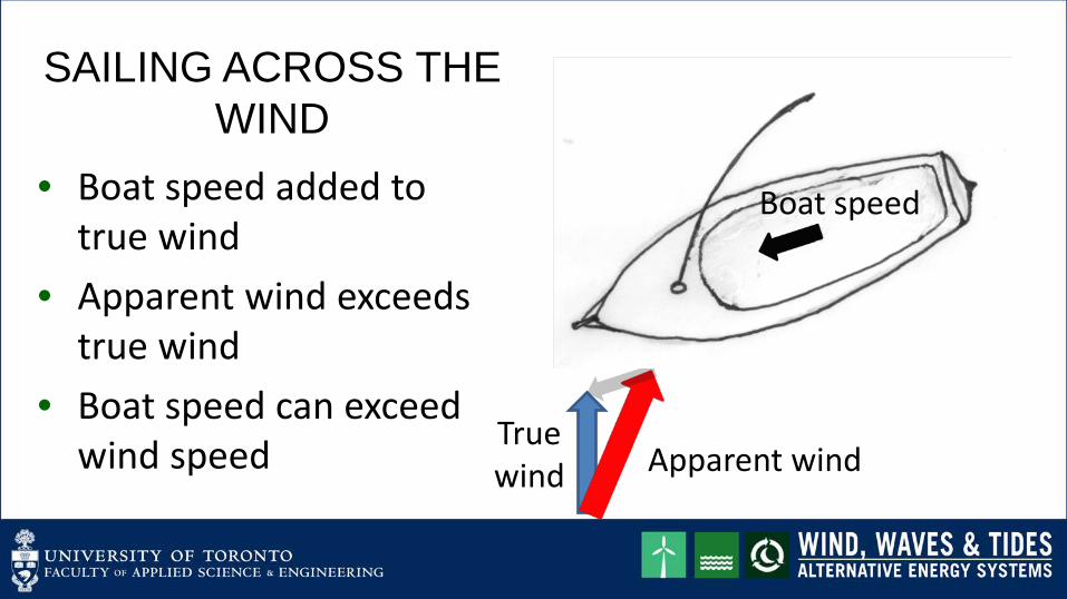
ANGLE OF ATTACK • Low angle of attack
– Lift exceeds drag • Moderate angle of attack
– Both increase but lift more than drag
• Steep angle of attack – Stall – More drag than lift
Lift Drag

LIFT AND DRAG COEFFICIENTS • Lift coefficient for lift force F
𝐶𝐿 =𝐿
12 𝜌𝜌𝑉𝑟𝑟𝑟2
• Drag coefficient for drag force D
𝐶𝐷 =𝐷
12 𝜌𝜌𝑉𝑟𝑟𝑟2
where A is the blade area (surface area wind flows over)
A = chord x blade length
Blade length

EFFECT OF ANGLE OF ATTACK
0
0.2
0.4
0.6
0.8
1
1.2
1.4
1.6
1.8
2
0 5 10 15 20
Lift
coef
ficie
nt
Angle of attack (degrees)
0
0.01
0.02
0.03
0.04
0.05
0.06
0.07
0.08
0.09
0 5 10 15 20
Drag
coe
ffic
ient
Angle of attack (degrees) CL and CD values calculated for SD7062 airfoil by Huahui Tan
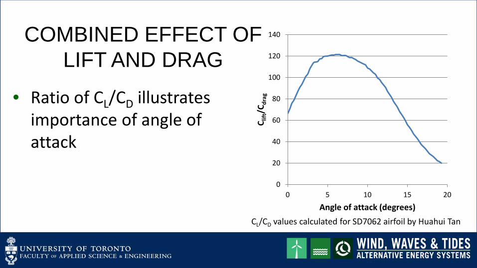
COMBINED EFFECT OF LIFT AND DRAG
• Ratio of CL/CD illustrates importance of angle of attack
0
20
40
60
80
100
120
140
0 5 10 15 20
C lift
/Cdr
ag
Angle of attack (degrees) CL/CD values calculated for SD7062 airfoil by Huahui Tan

BLADE SECTION GEOMETRY
r Wind
V0
v
V0
V1 Vrel
v
v = 2πrN where N =rotation
speed (rpm)
View of section from blade end Rotor axis Lift
Drag

ANGLE DEFINITIONS
V0
V1 Vrel
v
• Relative wind speed
𝑉𝑟𝑟𝑟 = 𝑉12 + 𝑣2
• Φ = relative wind angle
𝜑 = arctan𝑉1𝑣
• α = angle of attack • β = blade pitch angle
𝛽 = 𝜑 − 𝛼
Rotor axis
Lift Drag
φ β α

FORCES
V0
V1 Vrel
v
• Driving force rotates blade 𝐹𝐷𝑟𝐷𝐷𝐷𝐷𝐷 = 𝐿𝐿𝐿𝐿𝜑 − 𝐷𝐿𝐷𝐷𝜑
• Thrust force loads bearings 𝐹𝑡𝑡𝑟𝑡𝑡𝑡 = 𝐿𝐿𝐷𝐷𝜑 + 𝐷𝐿𝐿𝐿𝜑
𝐿 = 𝐶𝐿 ∙ 12𝜌𝜌𝑉𝑟𝑟𝑟2
𝐷 = 𝐶𝐷 ∙ 12𝜌𝜌𝑉𝑟𝑟𝑟2
View
Rotor axis
Lift Drag
φ β α

LIFT FORCE • Driving force on blade element:
𝐹𝐷𝑟𝐷𝐷𝐷𝐷𝐷 = 12𝜌𝜌𝑉𝑟𝑟𝑟
2 𝐶𝐿 ∙ 𝐿𝐿𝐿𝜑 − 𝐶𝐷 ∙ 𝐿𝐷𝐷𝜑
• Rotor speed v is one component of Vrel 𝑣 = 𝑟 ∙ 𝜔
where 𝜔= blade rotation frequency (radians/s)
𝐹𝐷𝑟𝐷𝐷𝐷𝐷𝐷 = 12𝜌𝜌 𝑉12 + 𝑟𝜔2 ∙ 𝐶𝐿 𝛼 ∙ 𝐿𝐿𝐿𝜑 − 𝐶𝐷 𝛼 ∙ 𝐿𝐷𝐷𝜑
where: 𝜑 = 𝑎𝑟𝐿𝑎𝑎𝐷 𝑉1𝑟𝑟
and 𝛼 = 𝜑 − 𝛽

FORCE DEPENDENCE ON ROTATING SPEED • SD7062 airfoil for illustration
– Blade tip radius R = 3.38m – V1 = 9.33m/s – β=15o – Two radii (1.8m, 3.35m) – Force/unit blade length
• 0
20
40
60
80
100
120
140
0 10 20 30
Forc
e /u
nit b
lade
leng
th
(arb
itrar
y un
its)
Rotation frequency (radians/s)
r = 1.8m
r = 3.35m
β= 15o

FORCE AT FIXED ROTATION SPEED • Often desirable to run rotor at
fixed speed to match generator synchronous speed
• Calculation shows effect of wind speed for fixed rotation speed.
• Large difference in force developed!
• Large wind turbines use blade pitch control – adjust β 0 5 10 15 20
Forc
e fr
om a
irfoi
l sec
tion
(arb
itrar
y un
its)
Wind speed (m/s)
r = 1.8m
β = 15o
Ω = 10

INTEGRATE OVER BLADE LENGTH • Define Power coefficient
𝐶𝑃 =𝑃𝑎𝑎𝑡𝑡𝑎𝑟12𝜌𝜌𝑉0
3
• Indicates the fraction of power available in the wind that is produced as electrical output:
• Depends on wind speed and on rotor speed
Blade length

POWER COEFFICIENT & TIP SPEED RATIO • Characterize rotor speed by tip
speed ratio:
𝑇𝐷𝑇 𝑆𝑇𝑆𝑆𝑆 𝑅𝑎𝑎𝐷𝐿 =2𝜋𝑅𝜋𝑉0
where: R = blade radius N = rotor speed (rpm) V0 = upstream wind speed
• TSR useful for all circumstances,
constant rotor speed or not 0 2 4 6
Pow
er co
effic
ient
Tip speed ratio
β = 15o

WHAT IS THE MAXIMUM POWER THAT CAN BE EXTRACTED FROM THE WIND?
• Betz limit is max power that can be extracted from the wind
𝑃𝑚𝑎𝑚 𝑤𝐷𝐷𝑖 𝑡𝑡𝑟𝑡𝐷𝐷𝑟 =12𝜌𝜌𝑉03
1627
• For Betz limit, CP = 0.593 • Real wind turbines have lower values of CP
SUMMARY - AERODYNAMIC LIFT-TYPE WIND ENERGY TECHNOLOGY
• Air passing over an airfoil shape (e.g. a wind turbine blade) generates lift and drag
• Blade angle of attack determines relative amounts of lift and drag
• Blade sees relative wind velocity, the vector sum of the true wind speed and the rotor speed
• Actual power output characterized by power coefficient CP, which depends on the tip speed ratio, the ratio of rotor tip speed to upstream wind speed.

PRACTICE EXERCISES

REFERENCES AND PHOTO CREDITS
References • Torrey, Volta, “Wind-Catchers; American Windmills of
Yesterday and Tomorrow,” The Stephen Greene Press, Brattleboro, Vermont, 1976.