Lecture 3 - Aalborg...
43
Lecture 3 Potential-Controlled Techniques in Potential Controlled Techniques in Electrochemical Sensing. Enzymatic Electrodes Enzymatic Electrodes.
Transcript of Lecture 3 - Aalborg...
Lecture 3
Potential-Controlled Techniques inPotential Controlled Techniques in Electrochemical Sensing.
Enzymatic ElectrodesEnzymatic Electrodes.
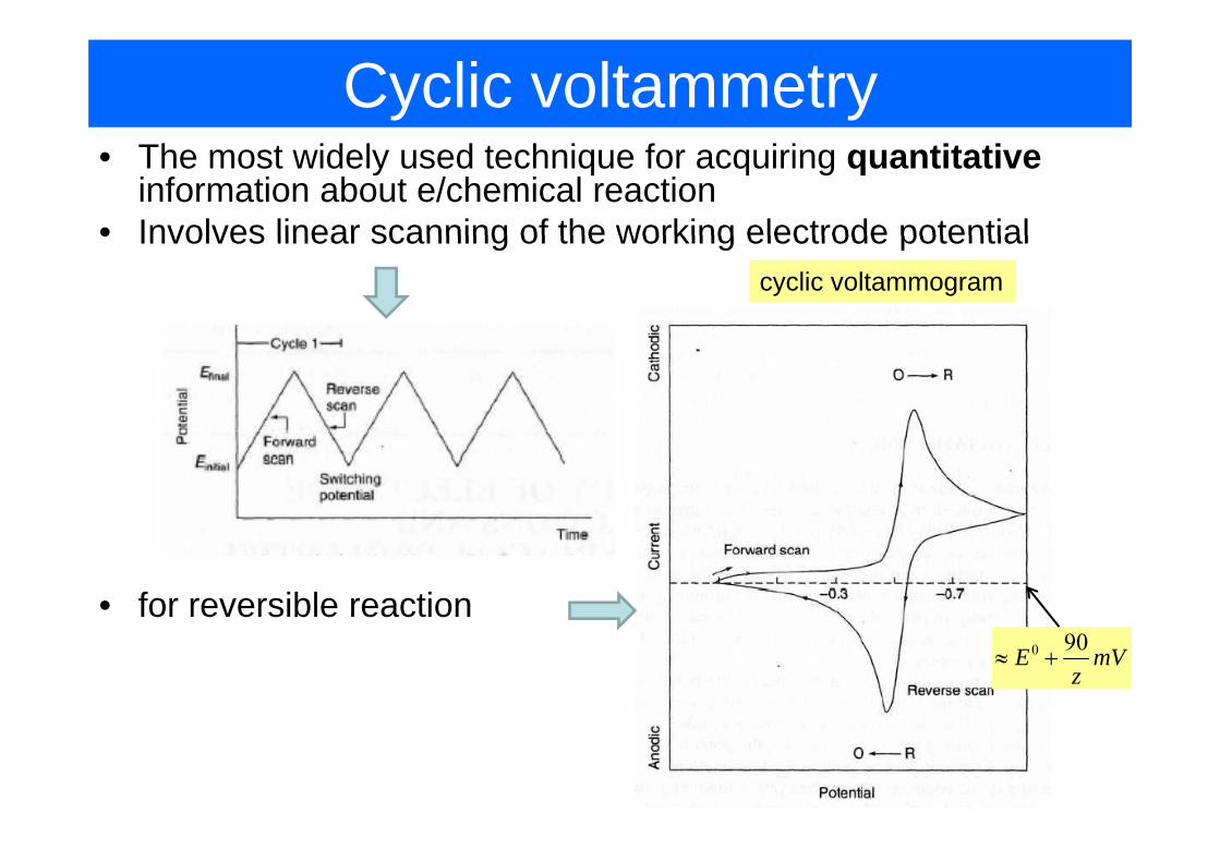
Cyclic voltammetry• The most widely used technique for acquiring quantitative
information about e/chemical reaction• Involves linear scanning of the working electrode potential• Involves linear scanning of the working electrode potential
cyclic voltammogram
• for reversible reaction0 90E mV
z≈ +
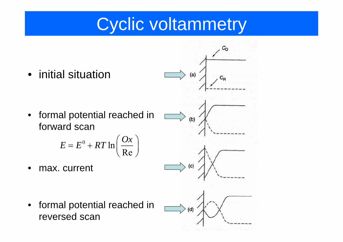
Cyclic voltammetry
• initial situation
• formal potential reached in forward scan
0 ln OxE E RT ⎛ ⎞= + ⎜ ⎟⎝ ⎠Re⎜ ⎟⎝ ⎠
• max. current
formal potential reached in• formal potential reached in reversed scan
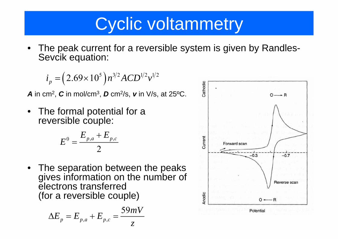
Cyclic voltammetry• The peak current for a reversible system is given by Randles-
Sevcik equation:
( )5 3 2 1 2 1 22.69 10pi n ACD v= ×
A i 2 C i l/ 3 D 2/ i V/ t 25ºCA in cm2, C in mol/cm3, D cm2/s, v in V/s, at 25ºC.
• The formal potential for a reversible couple:reversible couple:
, ,0
2p a p cE E
E+
=2
• The separation between the peaks i i f ti th b fgives information on the number of
electrons transferred(for a reversible couple)
, ,59
p p a p cmVE E Ez
Δ = + =
Cyclic Voltammetry
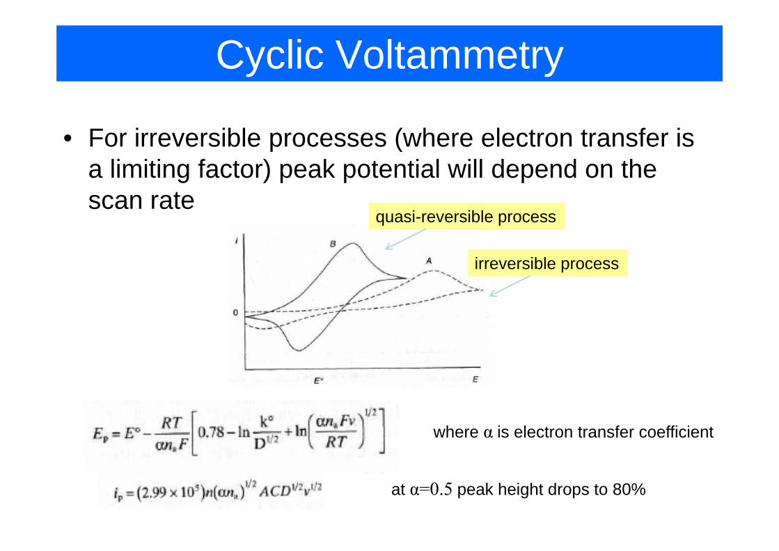
• For irreversible processes (where electron transfer is p (a limiting factor) peak potential will depend on the scan rate
i ibl
irreversible process
quasi-reversible process
where α is electron transfer coefficient
at α=0.5 peak height drops to 80%
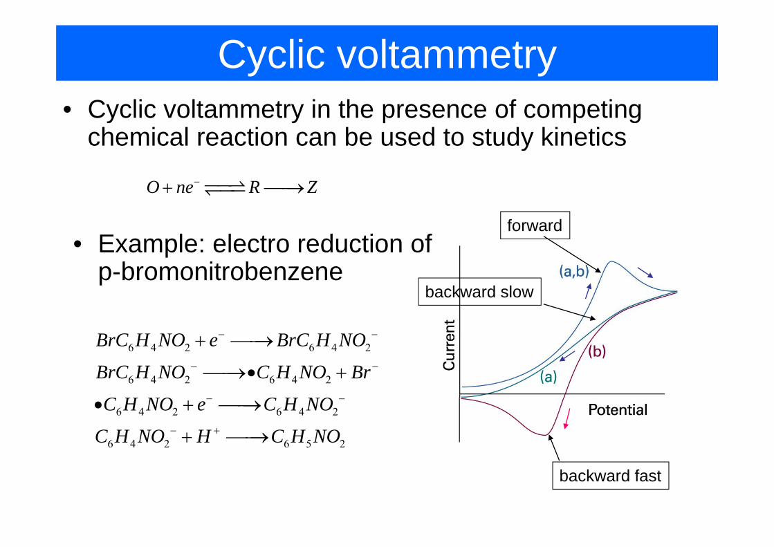
Cyclic voltammetry• Cyclic voltammetry in the presence of competing
chemical reaction can be used to study kineticsy
O ne R Z−+ ⎯⎯→
forward• Example: electro reduction of
p-bromonitrobenzene
B C H NO B C H NO− −
backward slowp-bromonitrobenzene
6 4 2 6 4 2
6 4 2 6 4 2
BrC H NO e BrC H NO
BrC H NO C H NO Br
C H NO C H NO
− −
+ ⎯⎯→
⎯⎯→• +
6 4 2 6 4 2
6 4 2 6 5 2
C H NO e C H NO
C H NO H C H NO
− −
− +
• + ⎯⎯→
+ ⎯⎯→
backward fast
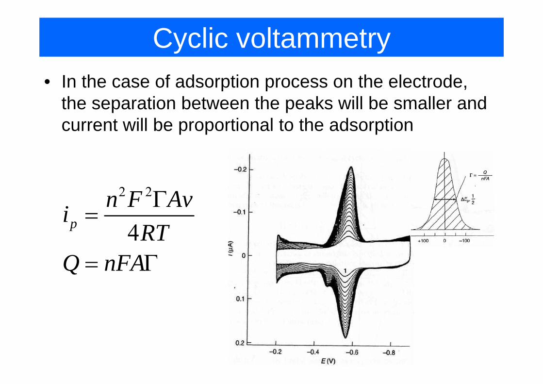
Cyclic voltammetry• In the case of adsorption process on the electrode,
the separation between the peaks will be smaller andthe separation between the peaks will be smaller and current will be proportional to the adsorption
2 2F AΓ2 2
4pn F Avi
RTΓ
=4RT
Q nFA= Γ
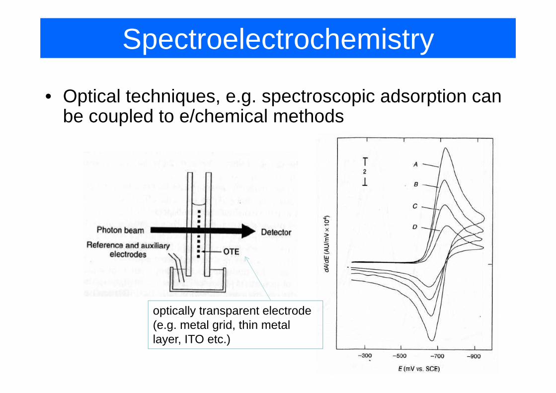
Spectroelectrochemistry
• Optical techniques, e.g. spectroscopic adsorption can be coupled to e/chemical methods
optically transparent electrode (e.g. metal grid, thin metal ( g g ,layer, ITO etc.)
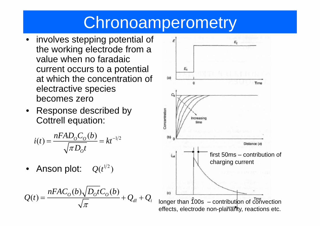
Chronoamperometryi l i i l f• involves stepping potential of the working electrode from a value when no faradaicvalue when no faradaic current occurs to a potential at which the concentration of electractive specieselectractive species becomes zero
• Response described byResponse described by Cottrell equation:
1 2( )( ) O OnFAD C bi k −1 2( )( ) O O
O
i t ktD tπ
= =
first 50ms – contribution of charging current
( ) ( )FAC b D tC b
g g• Anson plot: 1 2( )Q t
( ) ( )( ) O O O
dl i
nFAC b D tC bQ t Q Q
π= + + longer than 100s – contribution of convection
effects, electrode non-planarity, reactions etc.
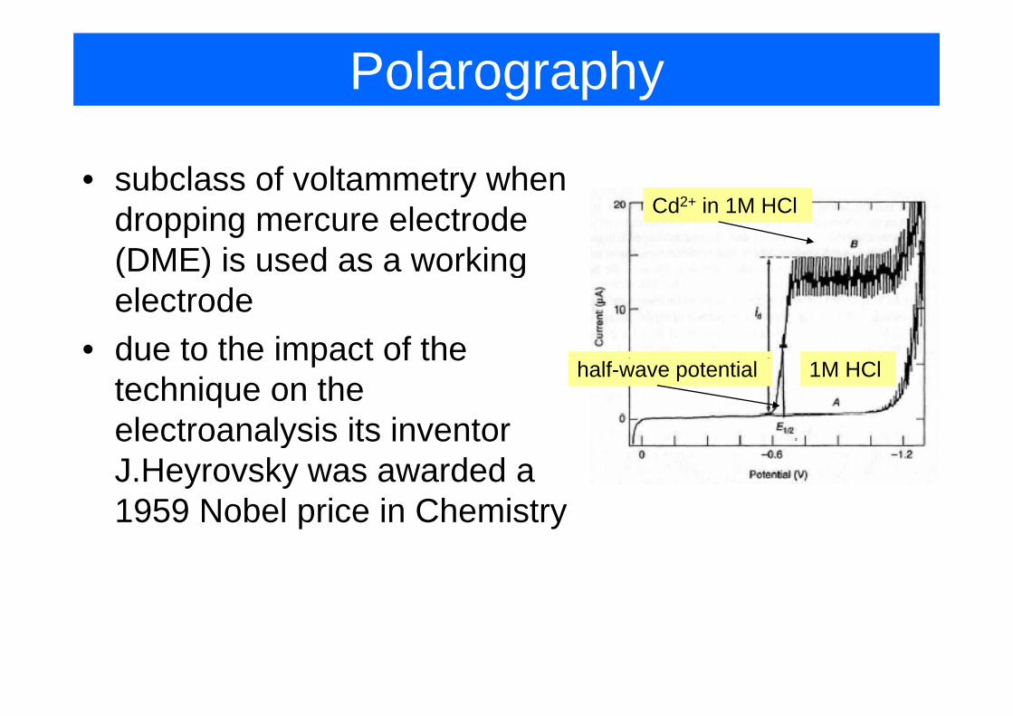
Polarography
• subclass of voltammetry when ydropping mercure electrode (DME) is used as a working
Cd2+ in 1M HCl
( ) gelectrode
• due to the impact of thedue to the impact of the technique on the electroanalysis its inventor
1M HCl half-wave potential
electroanalysis its inventor J.Heyrovsky was awarded a 1959 Nobel price in Chemistry1959 Nobel price in Chemistry
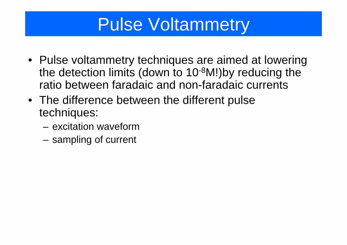
Pulse Voltammetry
• Pulse voltammetry techniques are aimed at lowering the detection limits (down to 10-8M!)by reducing the ratio between faradaic and non-faradaic currents
• The difference between the different pulse techniques: – excitation waveform– sampling of current
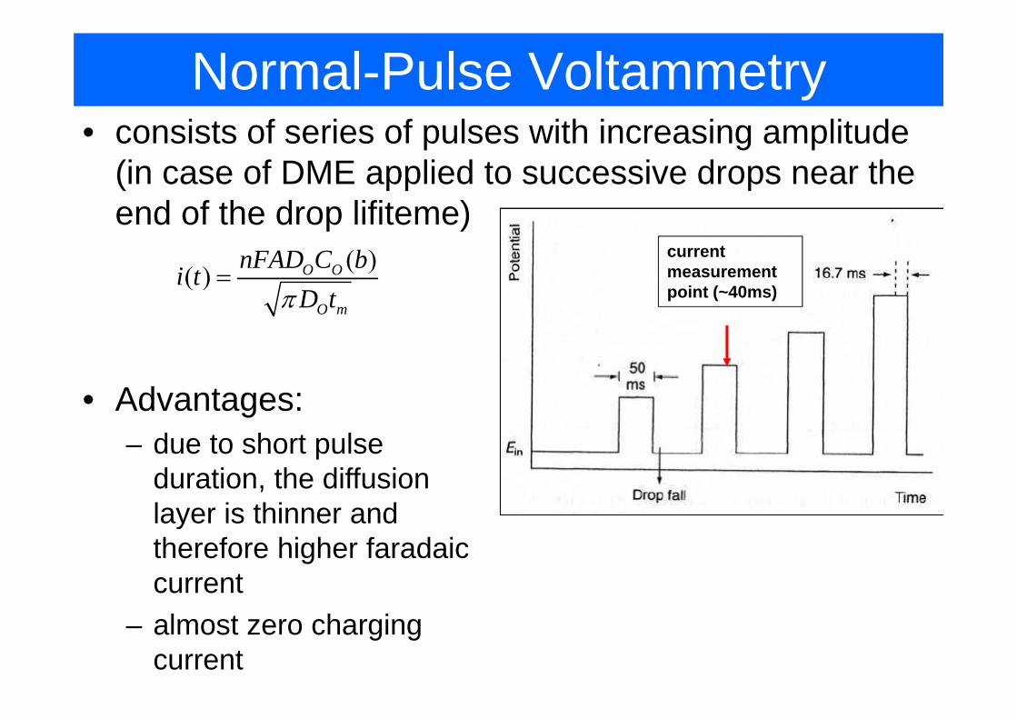
Normal-Pulse Voltammetry• consists of series of pulses with increasing amplitude
(in case of DME applied to successive drops near the end of the drop lifiteme)
current measurement ( )( ) O OnFAD C bi t =point (~40ms)
( )O m
i tD tπ
=
• Advantages:due to short pulse– due to short pulse duration, the diffusion layer is thinner andlayer is thinner and therefore higher faradaic current
– almost zero charging current
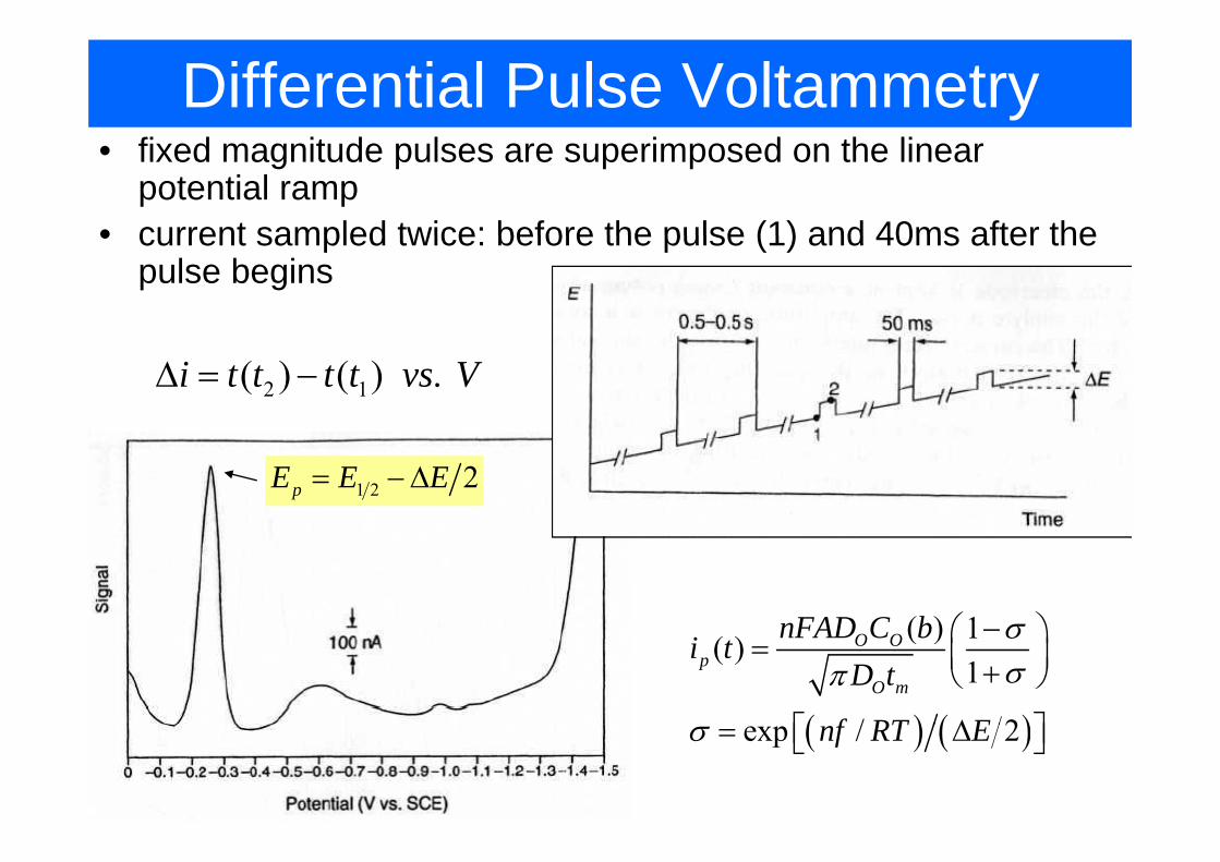
Differential Pulse Voltammetryfi d i d l i d h li• fixed magnitude pulses are superimposed on the linear potential ramp
• current sampled twice: before the pulse (1) and 40ms after the• current sampled twice: before the pulse (1) and 40ms after the pulse begins
2 1( ) ( ) .i t t t t vs VΔ = −
1 2 2pE E E= −Δ
( ) 1nFAD C b σ⎛ ⎞
( ) ( )
( ) 1( )1
/ 2
O Op
O m
nFAD C bi tD t
f RT E
σσπ
−⎛ ⎞= ⎜ ⎟+⎝ ⎠
Δ⎡ ⎤⎣ ⎦( ) ( )exp / 2nf RT Eσ = Δ⎡ ⎤⎣ ⎦
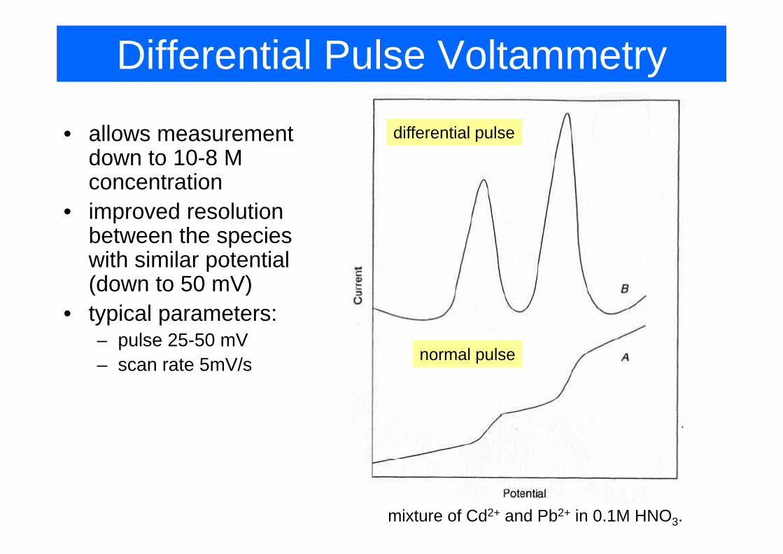
Differential Pulse Voltammetry
• allows measurement d t 10 8 M
differential pulsedown to 10-8 M concentration
• improved resolutionimproved resolution between the species with similar potential (d t 50 V)(down to 50 mV)
• typical parameters:pulse 25 50 mV– pulse 25-50 mV
– scan rate 5mV/s normal pulse
mixture of Cd2+ and Pb2+ in 0.1M HNO3.
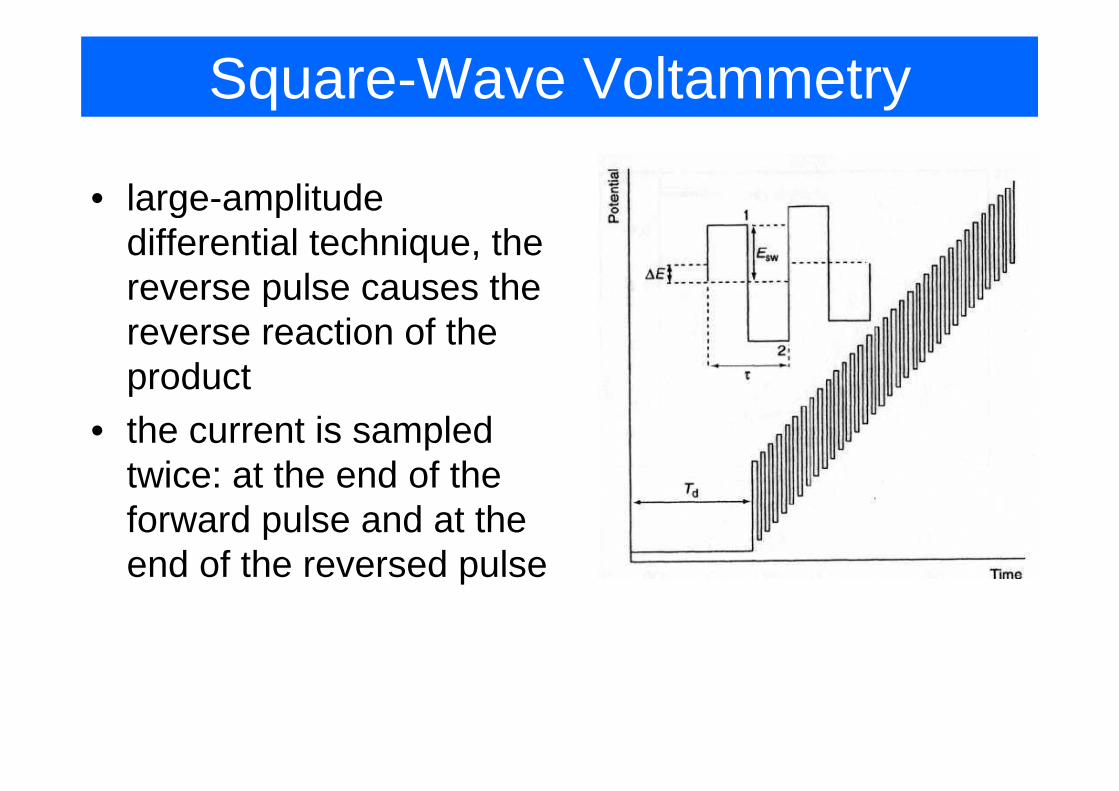
Square-Wave Voltammetry
• large-amplitude g pdifferential technique, the reverse pulse causes the preverse reaction of the productp
• the current is sampled twice: at the end of thetwice: at the end of the forward pulse and at the end of the reversed pulseend of the reversed pulse
Square-Wave Voltammetry
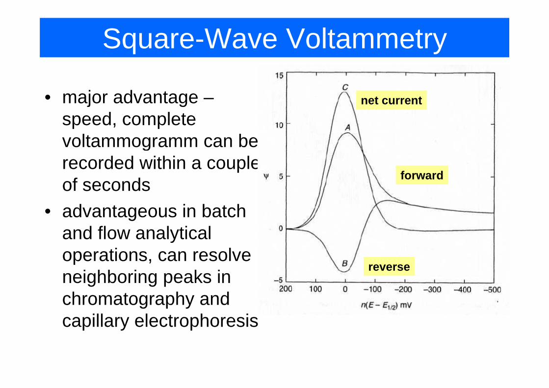
• major advantage – net currentj gspeed, complete voltammogramm can be grecorded within a couple of seconds forward
• advantageous in batch and flow analyticaland flow analytical operations, can resolve neighboring peaks in
reverseneighboring peaks in chromatography and capillary electrophoresiscapillary electrophoresis
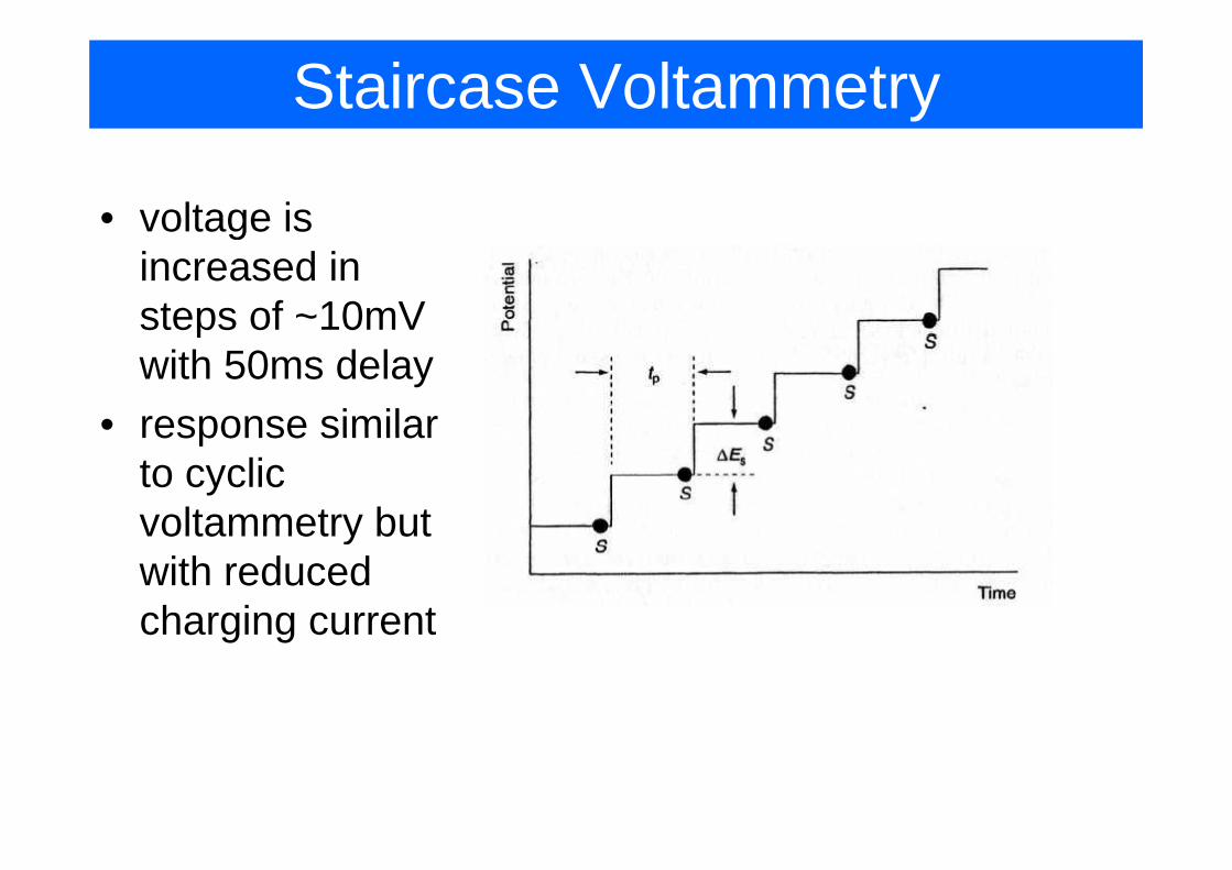
Staircase Voltammetry
• voltage is gincreased in steps of ~10mV pwith 50ms delay
• response similarresponse similar to cyclic voltammetry butvoltammetry but with reduced charging currentcharging current
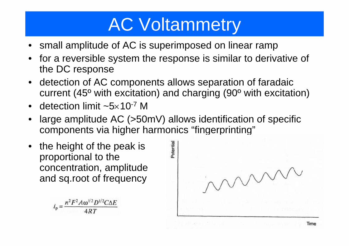
AC Voltammetry• small amplitude of AC is superimposed on linear ramp• for a reversible system the response is similar to derivative of
the DC responsethe DC response• detection of AC components allows separation of faradaic
current (45º with excitation) and charging (90º with excitation)current (45 with excitation) and charging (90 with excitation)• detection limit ~5×10⁻⁷ M• large amplitude AC (>50mV) allows identification of specific g p ( ) p
components via higher harmonics “fingerprinting”• the height of the peak is g p
proportional to the concentration, amplitude and sq root of frequencyand sq.root of frequency

Stripping analysis
• the idea:– first pre-concentrate the analyte on the surface of
the electrode– then strip (dissolve) the analyte and measure
• detection levels down to 10-10 M is feasibledetection levels down to 10 M is feasible• varios variations exists:
di i i l– anodic stripping voltammetry– potentiometric – adsorptive stripping– cathodic strippingpp g– abrasive stripping
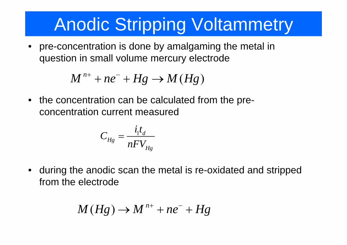
Anodic Stripping Voltammetry• pre-concentration is done by amalgaming the metal in
question in small volume mercury electrode
( )nM ne Hg M Hg+ −+ + →
• the concentration can be calculated from the pre-concentration current measured
1 dHg
Hg
i tCnFV
=g
• during the anodic scan the metal is re-oxidated and stripped f h l dfrom the electrode
( ) nM H M H+ −( ) nM Hg M ne Hg+→ + +
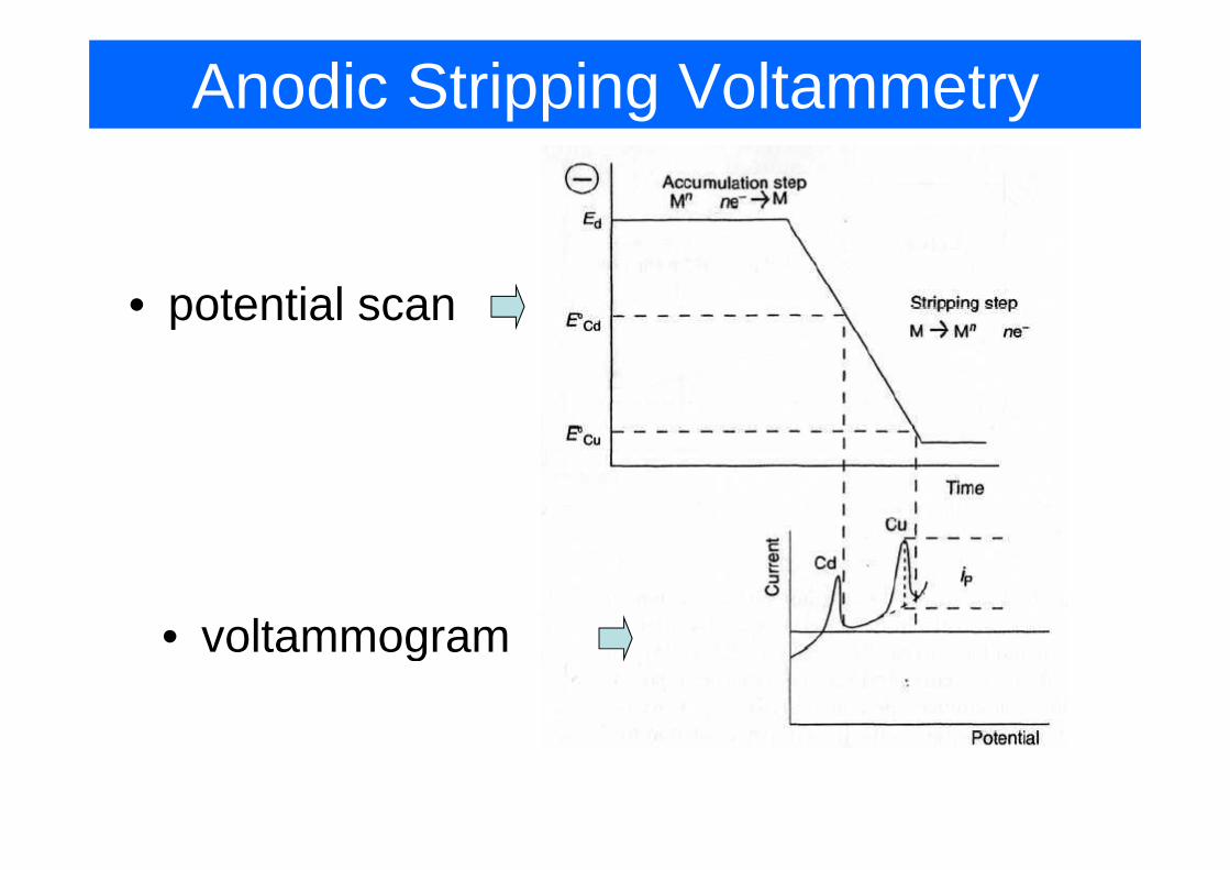
Anodic Stripping Voltammetry
• potential scan
• voltammogram• voltammogram
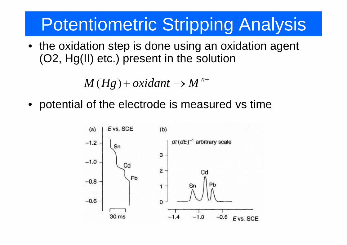
Potentiometric Stripping Analysis• the oxidation step is done using an oxidation agent
(O2, Hg(II) etc.) present in the solution
( ) nM Hg oxidant M ++ →
• potential of the electrode is measured vs time
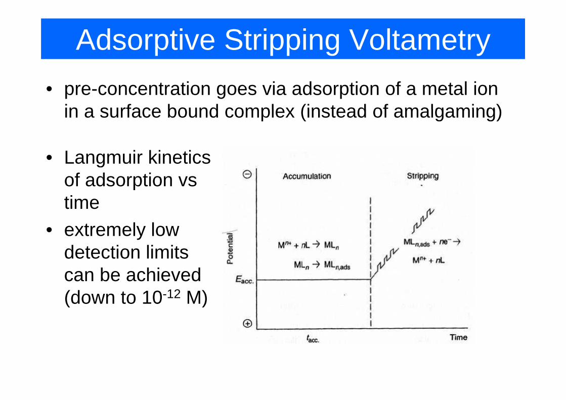
Adsorptive Stripping Voltametry• pre-concentration goes via adsorption of a metal ion
in a surface bound complex (instead of amalgaming)in a surface bound complex (instead of amalgaming)
Langmuir kinetics• Langmuir kinetics of adsorption vs timetime
• extremely low d t ti li itdetection limits can be achieved (d t 10 12 M)(down to 10-12 M)
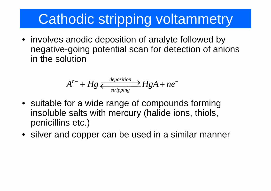
Cathodic stripping voltammetry• involves anodic deposition of analyte followed by
negative-going potential scan for detection of anions negative going potential scan for detection of anions in the solution
depositionn
strippingA Hg HgA ne− −⎯⎯⎯⎯→+ +←⎯⎯⎯⎯
• suitable for a wide range of compounds forming insoluble salts with mercury (halide ions, thiols, y (penicillins etc.)
• silver and copper can be used in a similar mannerpp
Abrasive stripping voltammetry
• mechanical (abrasive) transfer of solid material onto ( )an electrode surface (e.g. paraffin coated graphite)
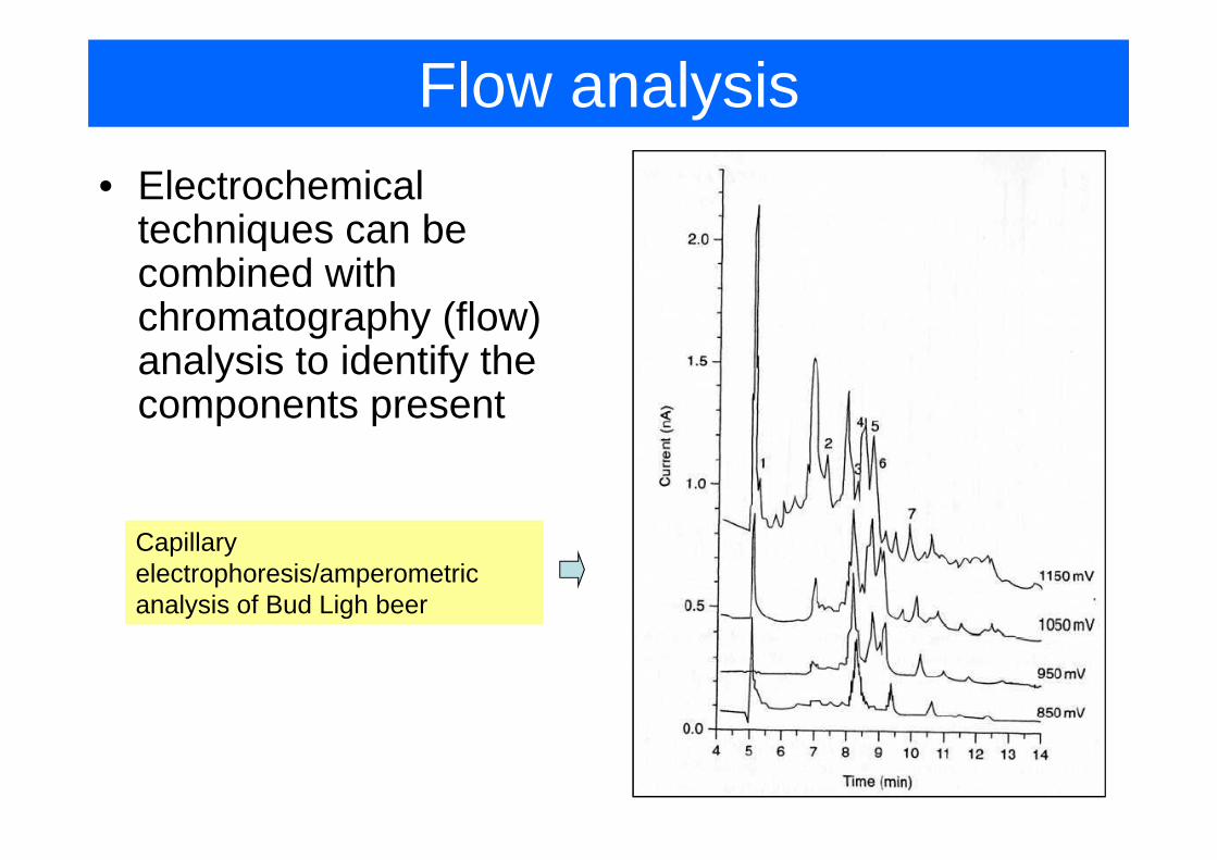
Flow analysis• Electrochemical
techniques can betechniques can be combined with chromatography (flow) g p y ( )analysis to identify the components present
Capillary electrophoresis/amperometric analysis of Bud Ligh beer
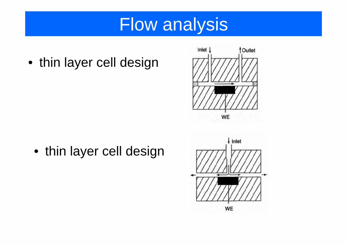
Flow analysis
• thin layer cell designaye ce des g
• thin layer cell design• thin layer cell design
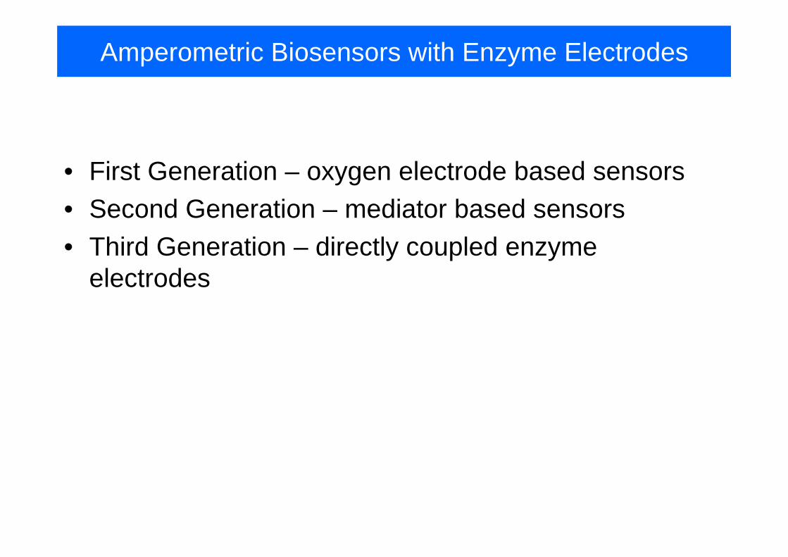
Amperometric Biosensors with Enzyme Electrodes
• First Generation – oxygen electrode based sensors• Second Generation – mediator based sensorsSecond Generation mediator based sensors• Third Generation – directly coupled enzyme
electrodeselectrodes
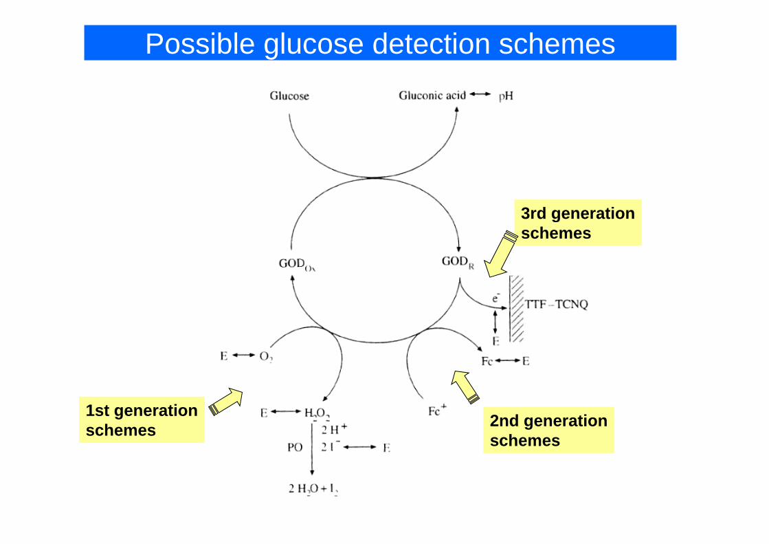
Possible glucose detection schemes
3rd generation3rd generationschemes
1st generationschemes 2nd generation
schemes
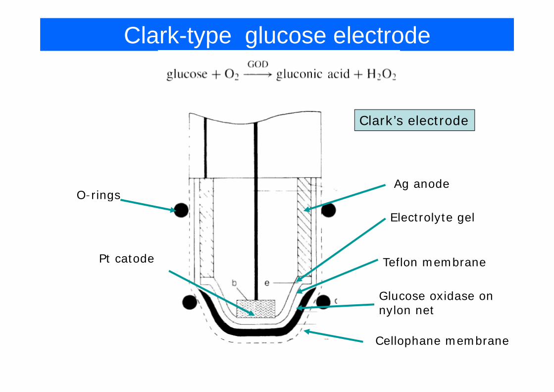
Clark-type glucose electrode
Clark’s electrode
Ag anodeO-rings
Electrolyte gel
O rings
Pt catode Teflon membrane
Glucose oxidase on nylon net
Cellophane membrane
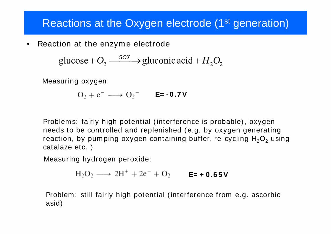
Reactions at the Oxygen electrode (1st generation)
2 2 2glucose gluconicacidGOXO H O+ ⎯⎯⎯→ +
• Reaction at the enzyme electrode
Measuring oxygen:
2 2 2g g
E=-0.7V
Problems: fairly high potential (interference is probable), oxygen needs to be controlled and replenished (e.g. by oxygen generating reaction, by pumping oxygen containing buffer, re-cycling H2O2 using
Measuring hydrogen peroxide:
catalaze etc. )
E=+0.65V
Problem: still fairly high potential (interference from e.g. ascorbic Problem: still fairly high potential (interference from e.g. ascorbic asid)
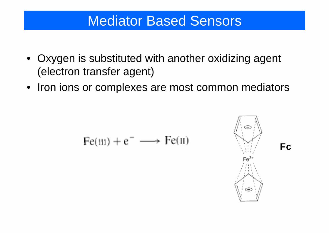
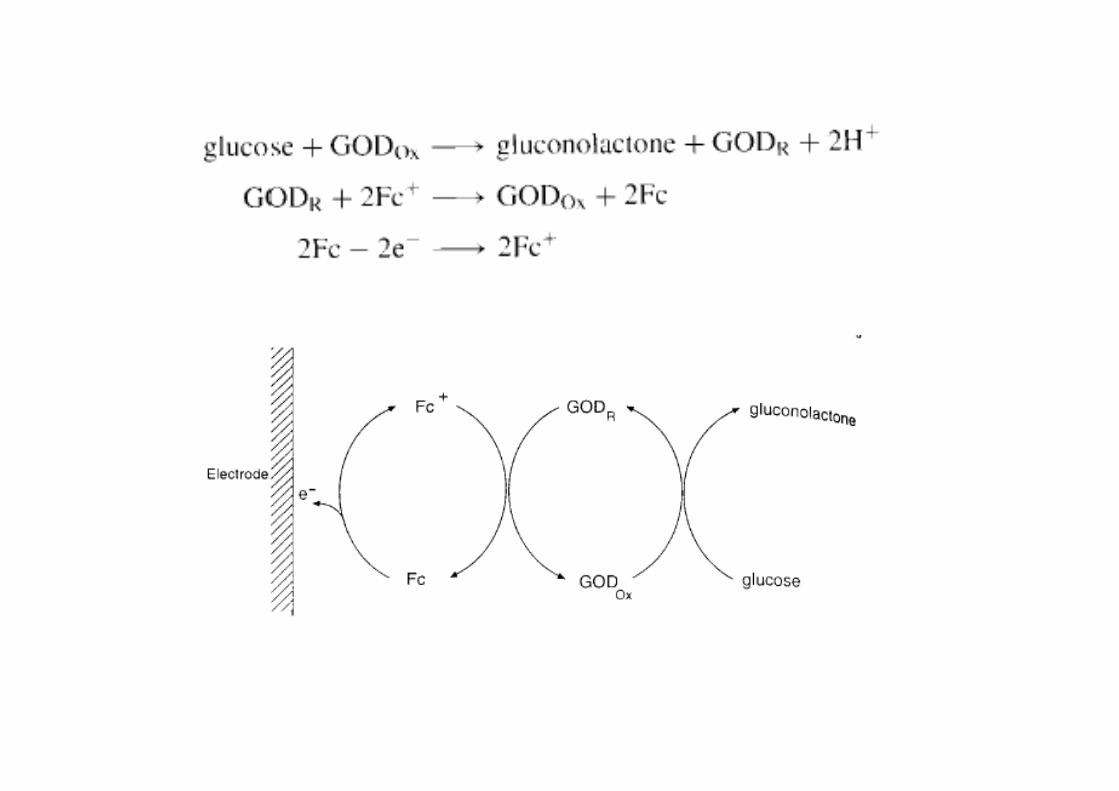
Mediator Based Sensors
• Oxygen is substituted with another oxidizing agent yg g g(electron transfer agent)
• Iron ions or complexes are most common mediatorsIron ions or complexes are most common mediators
FFc
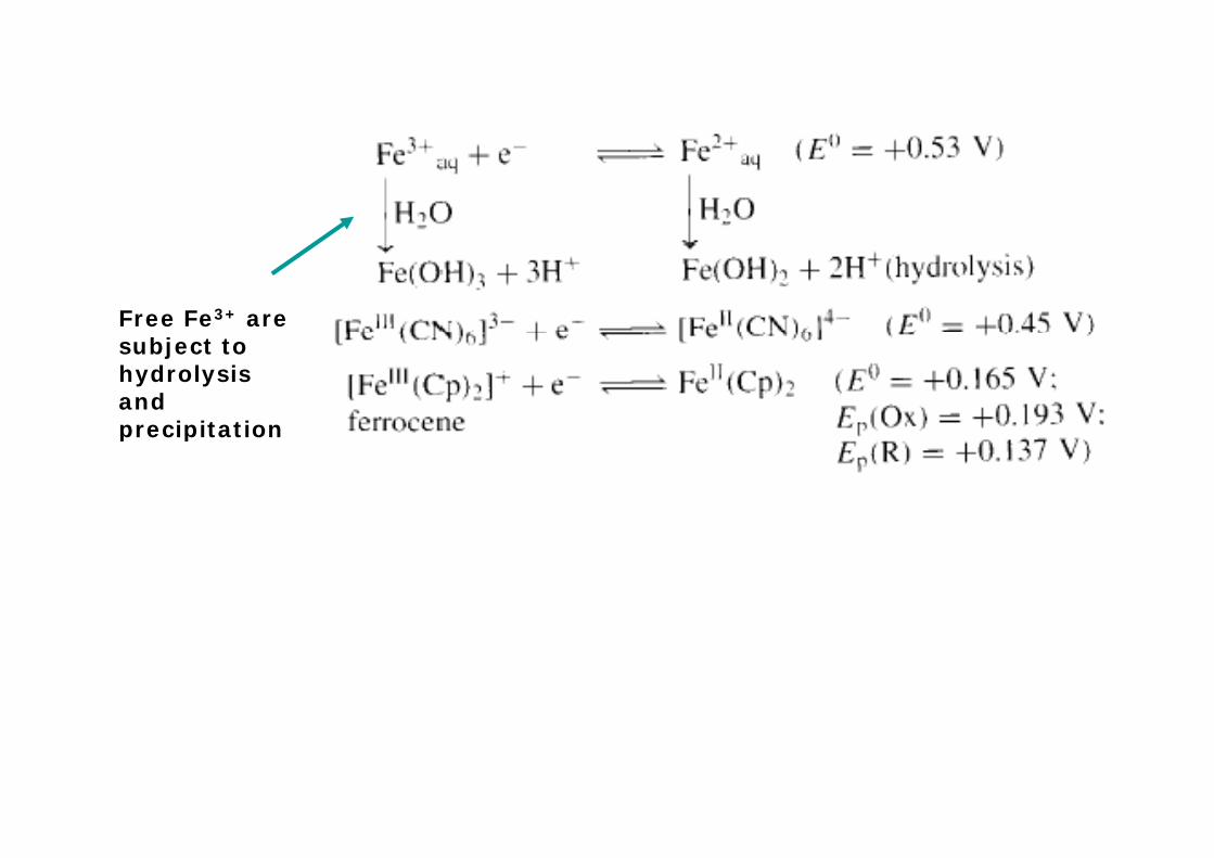
Free Fe3+ are subject to hydrolysis and precipitationprecipitation
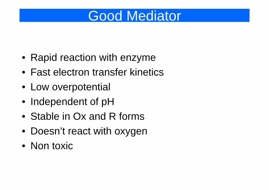
Good Mediator
• Rapid reaction with enzyme• Fast electron transfer kineticsFast electron transfer kinetics• Low overpotential• Independent of pH• Stable in Ox and R forms• Stable in Ox and R forms• Doesn’t react with oxygen• Non toxic
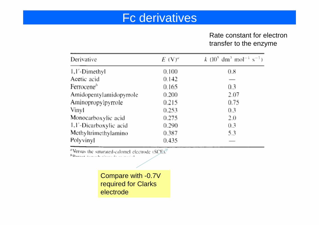
Fc derivativesRate constant for electronRate constant for electron transfer to the enzyme
Compare with -0.7V required for Clarks electrode
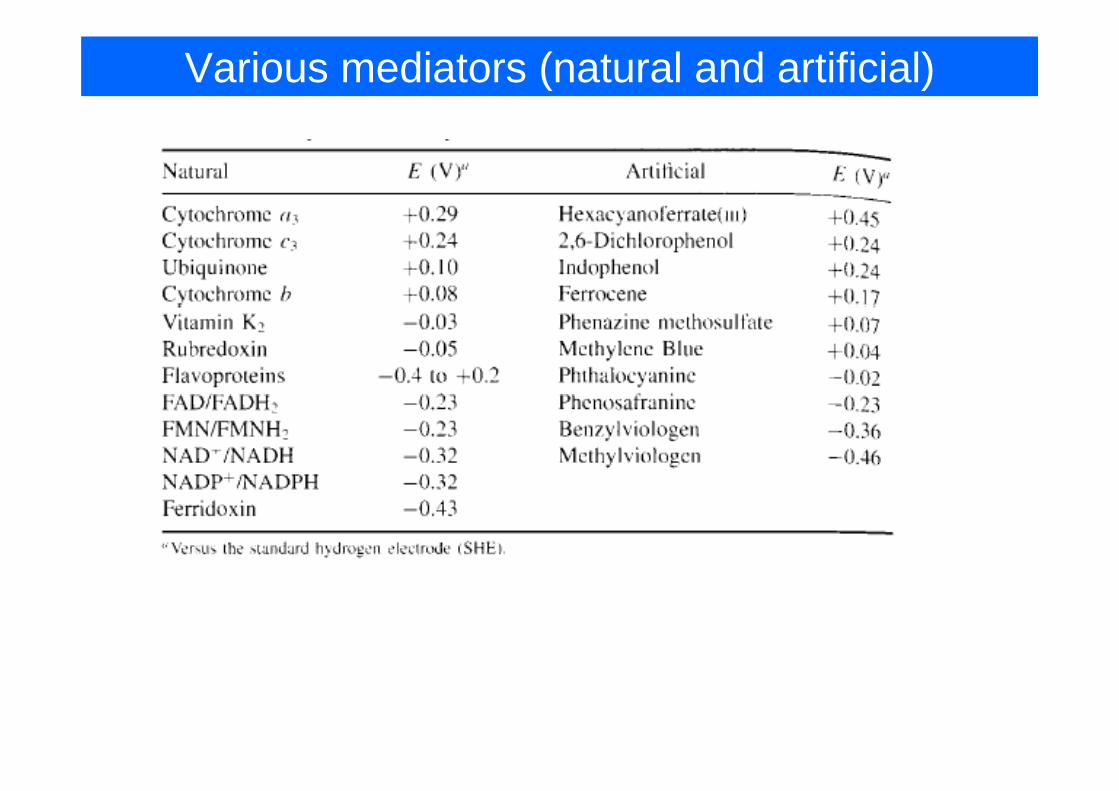
Various mediators (natural and artificial)
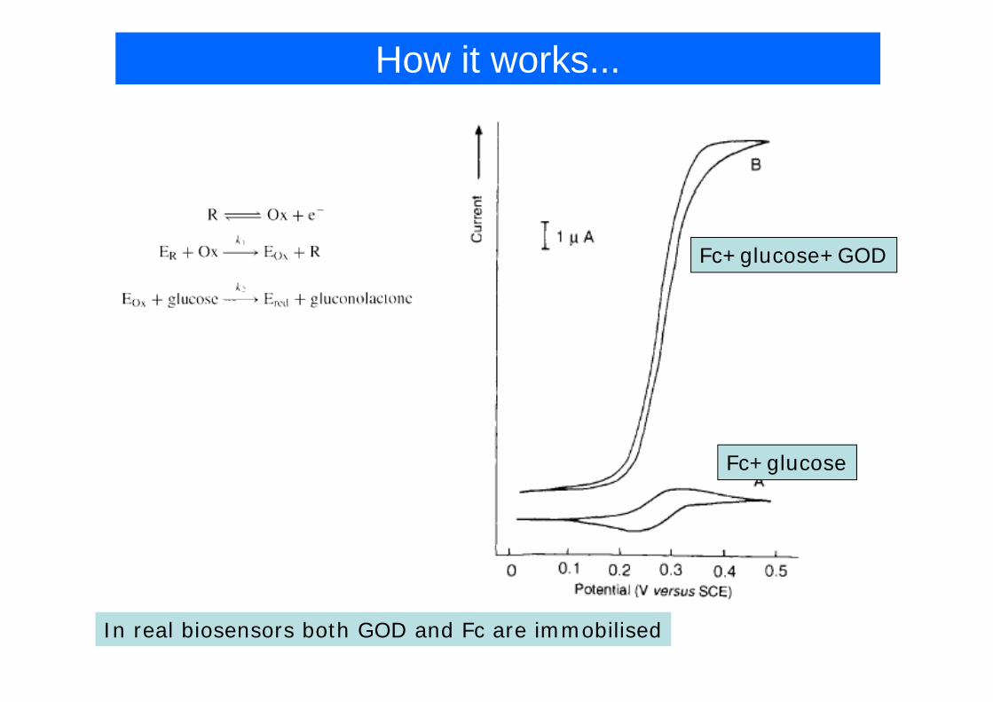
How it works...
Fc+glucose+GOD
Fc+glucose
In real biosensors both GOD and Fc are immobilised
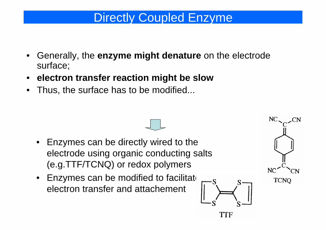
Directly Coupled Enzyme
• Generally, the enzyme might denature on the electrode fsurface;
• electron transfer reaction might be slow • Thus the surface has to be modified• Thus, the surface has to be modified...
• Enzymes can be directly wired to the• Enzymes can be directly wired to the electrode using organic conducting salts (e.g.TTF/TCNQ) or redox polymers(e.g.TTF/TCNQ) or redox polymers
• Enzymes can be modified to facilitate electron transfer and attachement
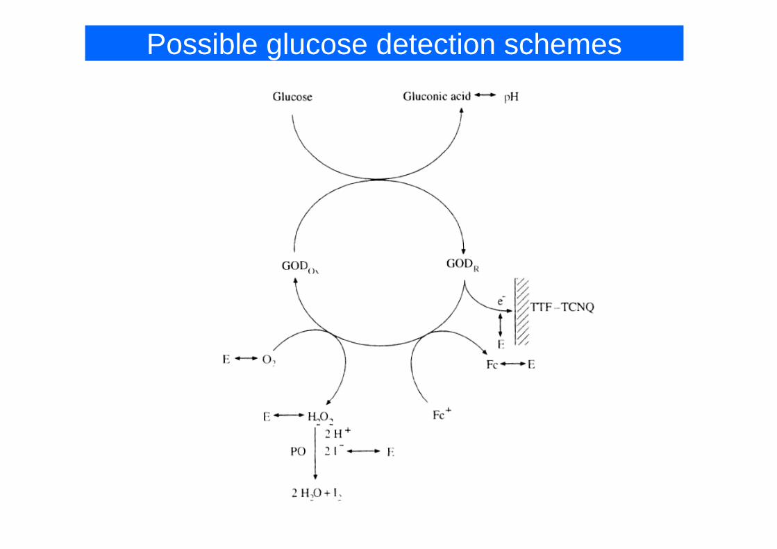
Possible glucose detection schemes
Design example: Glucose sensor
• Aim: for use by patient at home (should be simple, reliable d h )and cheap)
• Performance: blood glucose range 1.1-33.3 mM; precision 3-8%; test time 30s; life time 6 month8%; test time 30s; life time 6 month.
• Selective element: Glucose Oxidase – inexpensive, stable over long periodg
• Transducer: Amperometric (GOD+Fc) – cheap, reliable, easy read-out with LCD.I bili i l b di f l lif ( hi f il• Immobilisation: covalent bonding for long life (graphite foil coated with Fc, GOD immobilised)
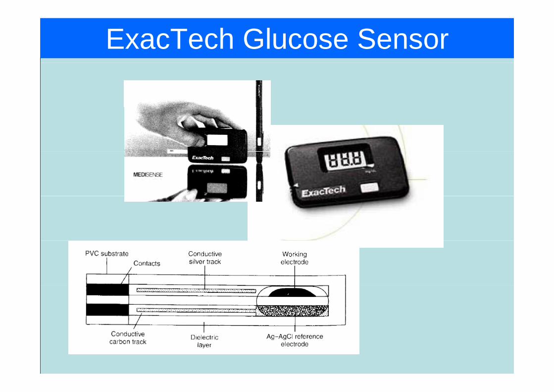
ExacTech Glucose Sensor