Lecture 23 27. quality of services in ad hoc wireless networks
121
Chandra Prakash LPU QOS IN AD-HOC NETWORKS
-
Upload
chandra-meena -
Category
Technology
-
view
1.048 -
download
1
Transcript of Lecture 23 27. quality of services in ad hoc wireless networks

Chandra
Prakash
LPU
QOS IN AD-HOC
NETWORKS
Objective
Introduction-
Issues and Challenges in Providing QoS in Ad HocNetworks
Classifications of QoS Solutions
MAC Layer Solutions
Network Layer Solutions;
QoS Model and Frameworks for Ad Hoc Wireless Networks
Typical QoS routing protocols
Conclusion and Open Issues

Introduction
Mobile ad hoc networks (MANETs) are infrastructureless
and intercommunicate using single-hop and multi-hop paths
Nodes act both as hosts and routers
Topology changes could occur randomly, rapidly, and
frequently
Routing paths are created and deleted due to the nodal
mobility

Applications of MANETs
Collaborative computing
Communications within buildings, organizations, ad hoc
conferences
Communications in battlefields and disaster recovery areas
Sensor networks
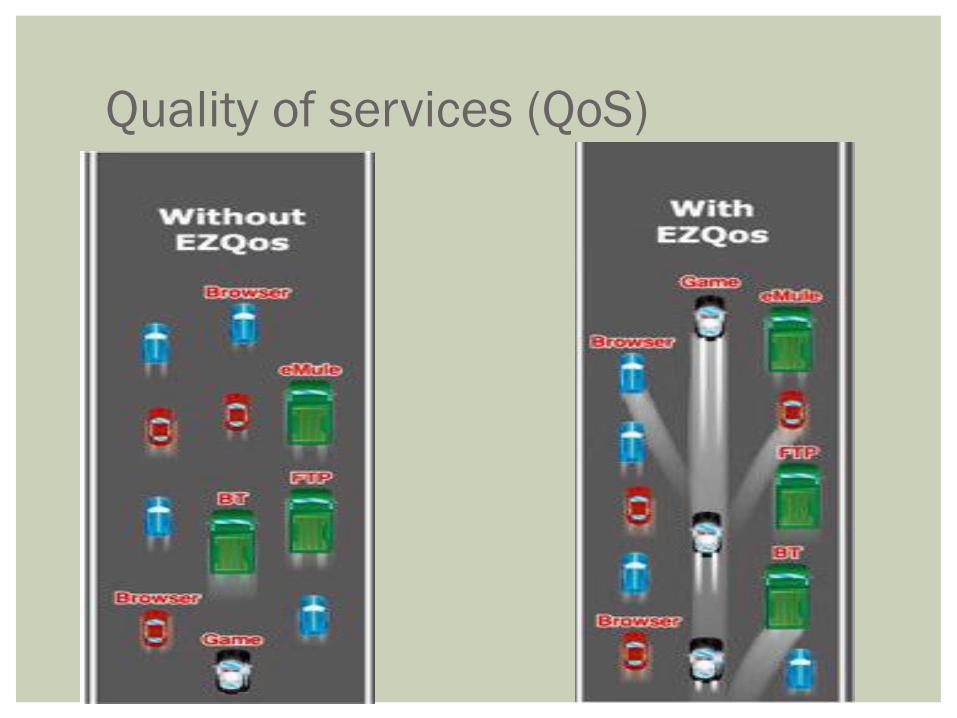
Quality of services (QoS)

Quality of Service (QoS)
QoS: A set of service requirements that are met by the network
while transferring a packet stream from a source to a destination
It is the performance level of a service offered by the network to
the user
Network or service provider provide different kinds of services to
the users.
Services : can be characterized by a set of measurable
prespecified service requirements such as min. bandwidth, max
delay, max. delay variance (jitter) and max packet loss.
QoS metrics could be defined in terms of one or a set of
parameters

Quality of Service (QoS) After accepting a service requirement from the user the network has to
ensure that the services requirements of the user’s flow are met, as per
the agreement, throughout the duration of the flow.
Network has to provide a set of services guarantees while
transporting a flow.
Video frame without QoS Support Video frame with QoS Support

Target of QoS Routing To find a feasible path between source and destination, which
satisfies the QoS requirements for each admitted connection
and
Optimizes the use of network resources
A
B C
D
E F
G
<2,4>
<3,3>
<4,5>
Tuple: <BW,D>
QoS requirement: BW≥4
<2,2>
<5,4>
<4,4>
<5,3> <4,2>
<3,4>
Shortest path
QoS Satisfying path

QoS in MANETs
QoS require negotiation between host and network
The use of QoS-aware applications are evolving in the wireless
environments
Resource limitations and variations adds to the need for QoS
provisioning
Real time traffic support in Ad Hoc Networks
Requires mechanisms that guarantee bounded delay and jitter
Can be classified two type of application
1. Hard real time application –
requires strict QoS guarantees
Include nuclear reactor control system , air traffic control systems and
missile control system
Delay may lead to disastrous results.

QoS in MANETs 2. Soft real time application
Can tolerate degradation in the guaranteed QoS to a certain extent
Eg: voice telephony, video-on-demand, and video conferencing
Delay may degrade the service but do not produce hazardous results.
Providing hard real time guarantee in MANET is extremely
difficult due to reasons such as unrestricted mobility of nodes,
dynamically varying network topology, time varying channel
capacity and the presence of hidden terminals .
Research community is currently focusing on providing
QoS support for soft real time applications
Use of MANETs in critical and delay sensitive applications
demands service differentiation

Different services require different QoS parameters.
– Multimedia
- Bandwidth, delay jitter & delay
– Emergency services
- Network availability
– Group communications
- Battery life
QoS parameters in ad hoc wireless networks:
11

12
Issues and challenges in providing QoS in ad hoc wireless
networks:
1. Dynamically varying network topology:
QoS session may suffer due to frequent path breaks.
Require new path formation but results in delay.
2. Imprecise state information
State information is inherently imprecise due to dynamic changes in
network topology and channel characteristics
Link-specific state information-
bandwidth, delay, delay jitter, loss rate, error rate, stability, cost, and
distance values for each link.
1. flow-specific state information –
session ID, source address, destination address, and QoS requirements of
the flow (such as maximum bandwidth requirement, minimum
bandwidth requirement, maximum delay, and maximum delay jitter).

13
3. Lack of central coordination
No central controller to coordinate the activity of nodes
4. Error prone shared radio channel
Radio channel broadcast by nature
Radio waves suffer from several impairments such as attenuation , multipath
propagation and inferences.
5. Hidden terminal problem
results in retransmission of packets, which may not be acceptable for flows
that have stringent QoS requirements
6. Limited resource availability
Heterogeneous nodes and networks
Bandwidth, battery life storage space, and processing capability are limited in
adhoc wireless networks.
7. Insecure medium:
De to broadcast nature communication is highly insecure

14
Design choices for providing QoS:
resource reservation: resources are reserved at
1.Hard state : at all intermediate nodes throughout the duration of the QoS
session
2.soft state: small time intervals
State approach:
1.Stateful approach: each node maintains either global state information
or only local state information
2.Stateless approach: such information is maintained at the nodes.
QoS approach: If QoS requirements of a connection are guaranteed to be
met
1.hard QoS approach : for the whole duration of the session.
2.soft QoS approach: are not guaranteed for the entire session

15
Design choices for providing QoS:
Hard state vs soft state resource reservation: Hard state
resources are reserved at all intermediate nodes along the path from
the source to the destination throughout the duration of the QoS
session and for soft state small time intervals are used
Stateful vs stateless approach: In the stateful approach, each node
maintains either global state information or only local state
information, while in the case of stateless approach no such
information is maintained at the nodes.
Hard QoS vs soft QoS approach: If QoS requirements of a
connection are guaranteed to be met for the whole duration of the
session, the QoS approach is termed as hard QoS approach. If the
QoS requirements are not guaranteed for the entire session, the QoS
approach is termed as soft QoS approach.
16
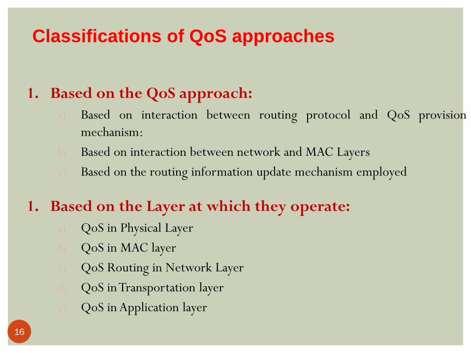
Classifications of QoS approaches
1. Based on the QoS approach:
a) Based on interaction between routing protocol and QoS provision
mechanism:
b) Based on interaction between network and MAC Layers
c) Based on the routing information update mechanism employed
1. Based on the Layer at which they operate:
a) QoS in Physical Layer
b) QoS in MAC layer
c) QoS Routing in Network Layer
d) QoS in Transportation layer
e) QoS in Application layer

17
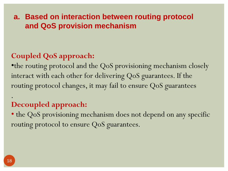
1. Based on the QoS approach:
18
Coupled QoS approach:
•the routing protocol and the QoS provisioning mechanism closely
interact with each other for delivering QoS guarantees. If the
routing protocol changes, it may fail to ensure QoS guarantees
. Decoupled approach:
• the QoS provisioning mechanism does not depend on any specific
routing protocol to ensure QoS guarantees.
a. Based on interaction between routing protocol
and QoS provision mechanism

19
b. Based on interaction between network and MAC
Layers
Independent QoS approach: the network layer is not dependent
on the MAC layer for QoS provisioning.
The dependent QoS approach: requires the MAC layer to assist
the routing protocol for QoS provisioning.

20
c. Based on the routing information update mechanism
employed
In the table-driven approach: each node in the network
maintains a routing table which aids in forwarding packets.
In the on-demand approach: no such tables are maintained
at the nodes, and hence the source node has to discover the
route on the fly.
The hybrid approach : bothabove

QoS Support in Physical Channels Wireless channel is time varying, the SNR in channels fluctuates
with time
Adaptive modulation which can tune many possible parameters according to current channel state is necessary to derive better performance
Major challenge: channel estimation – accurate channel estimation at the receiver and then the reliable feedback to the transmitter
Wireless channel coding needs to address the problems introduced by channel or multipath fading and mobility
Cross-layer issue: Joint source-channel coding takes both source characteristics and channel conditions into account

22
2. Based on the Layer at which they operate:

QoS Provisioning at the MAC Layer
For providing QoS guarantee for real-time traffic support in
wireless networks, several MAC protocols based on
centralized control have been proposed
For multihop networks:
The MAC protocol must be distributed in nature
It should solve the hidden and exposed terminal problems

24
QoS in MAC layer

25
1.

26

2. IEEE 802.11 In MANET radio channel operating in ISM band
IEEE 802.11 –is a CSMA/CA protocol; most deployed as media access
technology
2 modes of operation
Distributed coordination function (DCF) mode :
Doesn’t use any kind of centralized control ;
provide best effort services
Point coordination function (PCF) mode :
Requires an access point to coordinate the activity of all nodes in coverage
area
designed to provide real time traffic support in infrastructure-based wireless
network thus not applicable in MANET
DCF mode is must in implementation of IEEE802.11 standard for WLAN’s
while PCF is optional
27

IEEE 802.11 DCF IEEE 802.11 is a CSMA/CA protocol
In the distributed control function (DCF) mode: After the node has sensed the medium to be idle for a time
period longer than distributed inter-frame space (DIFS), it begins transmitting
Otherwise the node differs transmitting and backs off
When the medium becomes idle for a period longer than DIFS, the backoff timer is decremented periodically. The node starts transmission as soon as the timer expires
To reduce collisions, the sender and the receiver exchange RTS and CTS packets

QoS Support using IEEE 802.11
DCF
IEEE 802.11 DCF is a best-effort type control algorithm
The duration of backoff is decided by a random number
between 0 and the contention window (CW).
Service differentiation can be achieved by using different
values of CW
When packets collide, the ones with smaller CW is more
likely to occupy the medium earlier

Point Coordination Function (PCF)
Introduced to let stations have priority access to the wireless
medium
Uses a point coordinator (PC), which operates at an AP
PC decides which station should gain access to the channel
Useful only in infrastructure based network
PCF is not scalable to support real time traffic for a large
number of users.
Need of new mechanis
30

IEEE 802.11e
IEEE 802.11e – new standard to support real time traffic
(QoS in both infrastructure and infrastructure less networks
)
Enhanced DCF (EDCF)
Hybrid coordination function (HCF)
31

Enhanced DCF (EDCF)
Support real time traffic by providing differentiated and
distributed DCF access to the wireless medium
Each frame from the higher layer carries its user priority
(UP).
After receiving each frame, the MAC layer maps it into an
access category (AC)
Each AC has a different priority of access to the wireless up
to eight AC to support UP.
32

33
Hybrid Coordination function (HCF)
Combines feature of EDCF and PCF to provide the capability
of selectively handling MAC service data unit (MS-DU)
Has upward compatibility with DCF and PCF.
Usable only in infrastructure based BSS that provide QoS
Use a QoS aware point coordinator called HC .
34

3. DBASE Distributed bandwidth allocation/sharing/Extension
protocol supports multimedia traffic(both variable rate and constant bit
rate over adhoc WLANs.
In an adhoc WLAN, there is no fixed infrastructure to coordinate the
activity of individual stations.
For real time traffic, a contention based process is used in order to gain
access to the channel.
DBASE protocol permits real time station to acquire excess bandwidth
on demand.
The non real time stations regulate their accesses to the channel
according to the standard CSMA/CA protocol.
35

QoS-aware Routing at the Network
Layer Types of MANET routing protocols:
Proactive, table-based routing schemes
Reactive, on-demand routing schemes
Constraint-based routing schemes
These algorithms are based on the discovery of shortest paths
QoS-aware routing protocol should find a path that satisfies the QoS requirements in the path from source to the destination

Ticket based QoS routing protocol
Source node issues a certain number of tickets in probe packets
for finding a QoS feasible path.
Each probe packet carries one or more packets.
For example, when the source node issues three tickets, it
means a maximum of three paths can be probed in parallel.
37

Predictive location based QoS
routing protocol
On demand routing protocol
QoS aware admission control is performed.
The QoS routing protocol takes the help of an update protocol
and location and delay prediction schemes.
The update protocol aids each node in broadcasting its
geographic location and resource information to its neighbors.
The update protocol has two types of update messages, namely
type 1 update and type 2 update.
Each node generates a type 1 message periodically.
A type 2 message is generated when there is a considerable
change in the node’s velocity or direction of motion. 38

Cont…
From its recent update messages, each node can calculate an
expected geographical location where it should be located at
a particular instant and then periodically checks if it has
deviated by a distance greater than from this expected
location. If it has deviated, a type 2 message is generated.
39

Trigger-Based Distributed QoS Routing protocol (1)
TDR Link failure, it Utilizes GPS Each node maintains the local neighborhood
information and active routes only INIR (Intermediate Node Initiated Rerouting)
Rerouting is attempted from the location of an imminent link failure
SIRR (Source Initiated ReRouting) Rerouting is attempted from the source
Database management For each neighbor, each node maintains received
power level, current geographic coordinates, velocity, and direction of motion
40

Trigger-Based Distributed QoS Routing protocol (2)
Activity-based database The node maintains a source table (STn), a
destination table (DTn), or an intermediate table (ITn) Depending on the role of the node in current session
A flag indicating the node’s activity – NodActv
NodActv = 0, means idle
Also maintains an updated residual bandwidth (ResiBWn) which indicates its ability to participate in a session.
Databases are refreshed when packets belonging to the on-going sessions are received
41

Trigger-Based Distributed QoS Routing protocol (3)
Initial route discovery 1. The entry in source table is made, and NodActv sets to 0 (idle) 2. Selects the neighbors
1) lying closely toward the destination 2) with power level more than a threshold (Pth1) and forward them a route discovery packet
1. The intermediate node checks if such packet was received Yes discard
NO checks the ResiBW to meet the requirements
YES an entry in IT is made, and NodActv sets to 0 (idle)
forwards the packets with hop count +1
4. Upon receiving the first packet, if destination is able to satisfy the ResiBW and MaxBW, the route is made, and the ACK is sent back to source along the route
Route/ Reroute acknowledgement All the nodes along the route set the NodActv to 1 (active) and refesh
their ResiBW status
42

Trigger-Based Distributed QoS Routing protocol (4) Alternate Route Discovery
In SIRR When the received power level at an intermediate node falls below a threshold
Pth2, the intermediate node sends a rerouting indication to source
In INIR When the power level falls below the threshold Pth1 (Pth1 > Pth2), a status query
packet is sent toward the source with a flag route repair status (RR_stat) set to 0
If the upstream nodes are in rerouting process
o The RR_stat is set to 1, and reply back to the querying node
If the query packet reaches source, the packet is discarded
If the querying node receives no reply The SIRR could be triggered ( power level falls below Pth2)
Or simply give up the control of rerouting
Route Deactivation The source sends a route deactivation packet toward the destination The nodes received the packet update their ResiBW, and IT
43

Trigger-Based Distributed QoS Routing protocol (5)
Advantages
Reduced control overhead
Reduced packet loss during path breaks
Disadvantages
Threshold value? Fading / multi-path propagation/ velocity …etc
44

QoS AODV (1)
QoS Extensions to AODV protocol Modifications are made in routing table,
RouteRequest and RouteReply packet
The following fields are appended to routing table entry Max delay
Min available bandwidth
List of sources requesting delay guarantees
List of sources requesting bandwidth guarantees
45

Network layer solutions QoS AODV (2)
Max delay extension field In a RouteRequest msg.
Indicates the max time (sec) allowed for a transmission for the current node to the destination
The node compares its node traversal time (the time processing a packet) to the delay field in RouteRequest msg. If delay field is bigger, the msg. is discarded Otherwise, delay field = delay field – node traversal time
In a RouteReply msg. Indicates the current estimation of cumulative delay for the current
intermediate node to the destination The destination node reply a RouteReply msg. to the source with the
max delay field set to 0 Each node forwarding the RouteReply add its own node travaersal time, and
update the field
The routing table in the node is also updated
46
QoS AODV (3)
Min bandwidth extension field In a RouteRequest msg.
Indicates the min bandwidth (Kbps) that must be available along the path
The node compares its available bandwidth to the min bandwidth field in RouteRequest msg. If the field is smaller, the msg. is discarded
Otherwise, processes the msg. like usual AODV
In a RouteReply msg. Indicates the min bandwidth available on the route between the source
and destination
The destination node reply a RouteReply msg. to the source with the min bandwidth field set to infinity Each node forwarding the RouteReply compares its own link capacity to the
BW field, and update the field
The routing table in the node is also updated
47

QoS AODV (4)
List of sources requesting QoS guarantees A QoSLost msg. is generated when
An intermediate node’s traversal time increases, or
A link capacity decreases
The QoSLost msg. is forwarded to all sources that could be affected by the change (RouteReply msg. has been forwarded to)
Advantages Simplicity in provisioning QoS of extensions in AODV
Disadvantages Difficult to provide hard QoS
No resources are reserved along the path
Major part of delay is packet queuing delay, and contention at the MAC layer, not the packet processing time
48

Bandwidth Routing Protocol(1)
The BR protocol consists of 3 algorithms An end-to-end path bandwidth calcucation algorithm A bandwidth reservation algorithm
A standby routing algorithm
The goal of this protocol is to find a shortest path satisfying the bandwidth requirement
Only bandwidth is considered to be QoS parameter In TDMA, bandwidth is measured in terms of the number of free slots
available at a node Each frame is divided into 2 phases: control phase and data phase
Bandwidth : the set of common free slots between 2 adjacent nodes
The BR protocol assumes a half-duplex CDMA-over-TDMA system in which 1 packet can be transmitted in 1 slot
49

Bandwidth Routing Protocol(2)
Bandwidth calculation
1. pathBW(S,A)
= linkBW(A,S) = {2,5,6,7}
2. pathBW(S,B)
since linkBW(A,B) = {2,3,6,7},
we assign slots [6,7] on link(S,A), and [2,5] on link(A,B)
3. pathBW(S,C)
since linkBW(B,C) = {4,5,8},
we assign slot[4,8] on link(B,C)
4. pathBW(C,D)
since linkBW(C,D) = {3,5,8}
we assign slot[3,5] on link(C,D)
50

Bandwidth Routing Protocol(3)
Slot assignment Requires periodic exchange of bandwidth information Assigns free slots during the call setup
When a node receives a call setup packet, it checks if the slot that sender will use is free or not, it also
checks if there is free slots for forwarding the incoming packets Yes reserves the slot, updates the routing table, forwards the call
setup packet No sends a Reset packet back to sender along the path to release the
slots assigned for this connection along the path If the connection has been set up, the destination sends a reply
packet back to the source
The reservations are soft state to avoid resources lock-up due to the path breaks 51

Bandwidth Routing Protocol(4)
Standby routing mechanism To re-establish a broken connection, using DSDV
(Destination-Sequenced Distance Vector)
The neighbor with the shortest distance to destination becomes the next-
node in primary path
With the second shortest distance becomes the next-node on standby route
The standby route is not guaranteed to be link- or node-disjoint
if a primary path fails, and the backup path satisfies the QoS requirements, a new path is set up by sending a call setup packet hop-by-hop to the destination
52

Bandwidth Routing Protocol(5) Advantages
Efficient bandwidth allocation scheme
The standby routing mechanism reduces the packet loss during path breaks
Disadvantages Impossible for a new node to enter the network
If a node leaves, the corresponding slot remains unused, there’s no way to reuse such slots The model needs a unique control slot in control phase of
superframe for each node in the network
53

On-Demand QoS Routing protocol(1)
In OQR, routing is on-demand. Therefore, there is no need to exchange control information periodically
Maintain routing table at each node
OQR is similar to bandwidth routing protocol (BR) Network is time-slotted
Bandwidth is the key parameter
Uses the path bandwidth calculation to measure the end-to-end available bandwidth
54

On-Demand QoS Routing protocol(2)
Route discovery Source node floods network with QRREQ packet, which has following
fields: Packet type, source ID, destination ID, sequence num, route list, slot array list
data and TTL
The pair {source ID, sequence num} uniquely identify the packet
A node N receiving a QRREQ performs the following steps 1. if the packet with same {source ID, seq. num.} is received, the packet is
discarded
2. else, N checks its address in route list. If it is in the list, the packet is discarded
3. else, -1) TTL = TTL -1, if TTL ==0, the packet is discarded
-2) calculate the BW from the source to N, if it doesn’t satisfy the QoS requirements, the packet is discarded
-3) N appends the address to the route list, and re-broadcast the packet
55

On-Demand QoS Routing protocol(3)
Bandwidth reservation The destination may receive many QRREQ packets,
it selects the least-cost path among them
The {route list, slot array list} from QRREQ is copied to QRREP packet, and is sent back to source According route list field
All the intermediate nodes receiving the QRREP packet reserve the bandwith According to the slot array list field
The reservation is soft state
56

On-Demand QoS Routing protocol(4)
Reservation failure Due to
Route breaks
The free slots is occupied by other connections
When reservation fails, the node sends a ReservFail packet back to source And source selects the next feasible path
If no connection can be set up, the destination broadcasts a NoRoute packet to inform the source node
57

On-Demand QoS Routing protocol(5)
Route maintenance When a route breaks
The upstream sends a RouteBroken packet to the source
The upstream sends a RouteBroken packet to the source
All the nodes receiving the RouteBroken packet frees the reserved slots, and drop the data packet belonging to the connection
Source restarts the route discovery procedure
Advantage Low control overhead
Disadvantage The network needs to be fully synchronized
High connection setup time 58

On-demand Link-State Multipath QoS Routing protocol(1)
OLMQR idea: Finding 1 single path satisfying all the QoS requirements is
very difficult
Searches mutlipath satisfying required QoS
The BW requirement is split into sub-BW requirements
Uses CDMA-over-TDMA channel model
In this protocol The source floods QRREQ packets,
destination collects these packets, selects multiple paths, and sends the reply back to the source
The operation of this protocol consists of 3 phases On-demand link state discovery
Unipath discovery
Multipath discovery and reply
59

On-demand Link-State Multipath QoS Routing protocol(2)
On-demand Link-state Discovery A QRREQ packet contains the following fields
Source ID, Destination ID, node history, free time-slot list, bandwidth requirements, TTL
When receiving QRREQ, 1. Node N checks its address in route list. If it is in the list, the packet is discarded
2. else,
-1) TTL = TTL -1; if TTL == 0, the packet is discarded
-2) add its add in node history field, and re-broadcasts the packet
Build a partial view of network
60

Unipath discovery Build 2 trees: T and TLCF
Given a path SAB … K D, and a = BW(S,A), b= BW(A,B) …
Build T: 1.) Root is represented as abcd…xy
2.) ab means time slot is reserved
3.) build child abcd…, abcd…, abcd…, … ,abc…xy. Recusively
4.) the reserved time slots are calculated in every link
Build TLCF: Sort the reserved time slots in the same level in ascending order
from left to right
61

Unipath discovery, an example
S A B D
a 2,5,9,10
b 1,5,8,9
c 1,6,8,9
Build tree T:
abc
abc
c
abc
a
Build tree TLCF:
3
1
2 abc
c a
abc
abc
3
1
2
3 3 62

2 unipaths are found S,A,B,D
2 time-slots path bandwidth
S,E,F,D
1 time-slot path bandwidth
63

Multipath discovery and reply The destination initiates the multipath discovery
operation by using unipath operation The sum of path bandwidths fulfills the original bandwidth
request Determines the max achievable path bandwidth of each
path
The destination sends a reply packet back to source along the path, and all nodes on the path reserves the resources
Advantage Better average call acceptance rate
Disadvantage High control overhead to maintain and repair paths
64

Asynchronous slot allocation strategies(1)
AQR
Uses RTMAC (real time MAC), and is an extension of DSR (dynamic source routing)
3 phases Bandwidth feasibility test phase
Bandwidth allocation phase
Bandwidth reservation phase
65

Bandwidth feasibility test phase RouteRequest packet
If enough bandwidth is available, the packet is forwarded The routing loop is avoided by identifying <seq. num. ,
source ADD. ,and traversed path informations. Offset time field records the sum of processing time in all
nodes Used to estimate the propagation delay of transmission Reduces the synchronization problem
The destination selects a shortest path with enough bandwidth And construct a data structure called QoS frame for every
link in the path To calculate the free bandwidth slots
66

Bandwidth allocation phase A bandwidth allocation strategy to assign free slots
to each intermediate link in the path Early fit reservation
Minimum bandwidth-based reservation
Position-based hybrid reservation
K-hopcount hybrid reservation
The information is included in RouteReply packet through the path to the source
67

Slot allocation strategies Early fit reservation (EFR)
1. Order the links in the path from source to destination
2. Allocate the first available free slot for the first link in the path
3. For each subsequent link, allocate the first immediate free slot after the assigned slot in the previous link
4. Continue step 3 until the last link is reached
Attemps to provide the least end-to-end delay
End-to end delay can be obtained as
tsf * (n-1) /2
n : hop count, tsf : the duration of the superframe
68

69

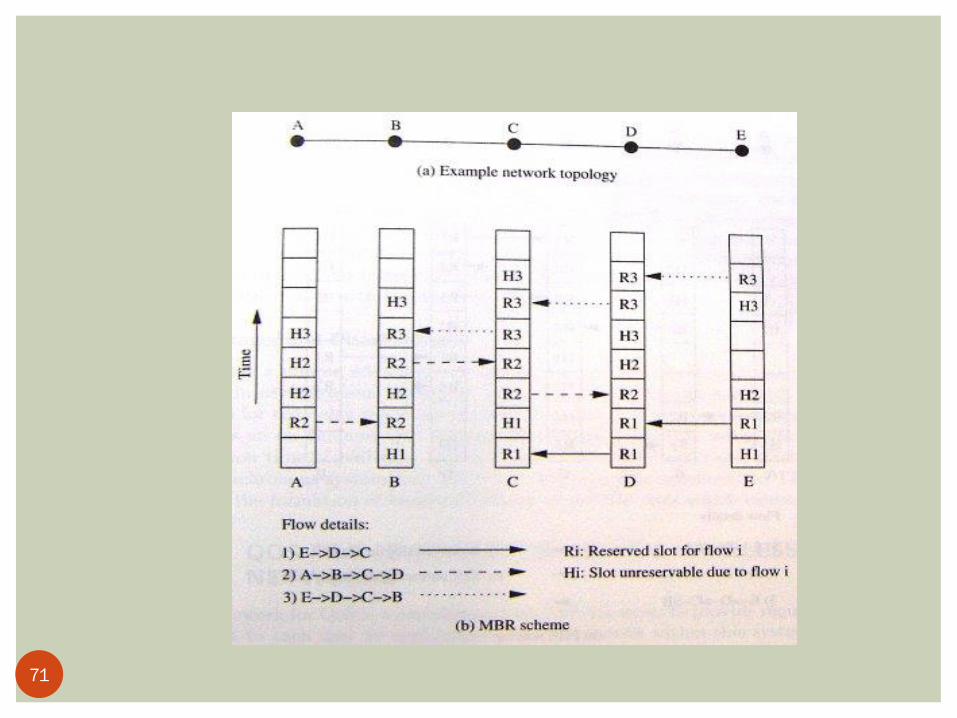
Minimum bandwidth-based reservation (MBR) 1. Order the links in the non-decreasing order of free bandwidth
2. Allocate the first free slot in the link with lowest free bandwidth
3. Reorder the links, and assign the first free slot on the link with lowest bandwidth
4. Continue step3 until bandwidth is allocated for all links
Allocates the badwidth in increasing order of free bandwidth
The worst case end-to-end delay can be (n-1)* tsf
70
71
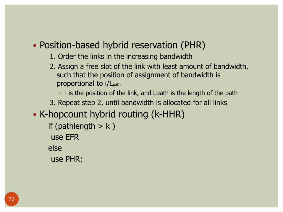
Position-based hybrid reservation (PHR) 1. Order the links in the increasing bandwidth
2. Assign a free slot of the link with least amount of bandwidth, such that the position of assignment of bandwidth is proportional to i/Lpath
o i is the position of the link, and Lpath is the length of the path
3. Repeat step 2, until bandwidth is allocated for all links
K-hopcount hybrid routing (k-HHR) if (pathlength > k )
use EFR
else
use PHR;
72

73

Advantages Provide end-to-end bandwidth reservation in asynchronous
networks
The slot allocation strategies can be used to plan for the delay requirements
Dynamically choose appropriate algorithms
disadvantages Setup and reconfigure time can be high
On-demand routing
Bandwidth efficiency may not as high as fully synchronized TDMA system Formation of bandwidth holes (short free slots can’t be used)
74

QoS frameworks for Ad Hoc wireless networks
75

QoS frameworks for Ad Hoc wireless networks
A framework for QoS is a complete system that attempts to provide required/promised services to each user
The key component is QoS service model To serve users on a per session basis or on a per class
basis
The other key components Routing protocol QoS resource reservation signaling Admission control Packet scheduling
76

QoS frameworks for Ad Hoc networks
QoS models(1)
In wired network, IntServ and DiffServ have been proposed IntServ provides QoS on a per flow basis
3 types of services Guaranteed service Controlled load service, Best effort service
RSVP is used Not scalable for internet
DiffServ Flows are aggregate into service classes
Both service model cant directly applied to ad hoc wireless networks
77

QoS frameworks for Ad Hoc networks
QoS models(2)
FQMM Flexible QoS model for mobile ad hoc networks
A hybrid service model Per flow granularity of IntServ
Aggregation of services into classes in DiffServ
Assumes that the number of flows requiring per flow QoS services is much less than the low-priority flows
Nodes are classified into 3 different categories Ingress node (source)
Responsible for traffic shaping
Interior node (intermediate relay node)
Egress node (destination)
High priority flows are provided with per flow QoS services
Lower priority flows are classified into service classes 78

QoS frameworks for Ad Hoc networks
QoS models(3)
79

QoS frameworks for Ad Hoc networks
QoS models(4)
Advantages Provides the ideal per flow QoS services Overcomes the scalability problem
Disadvantages Several issues remain un-solved
Decision upon traffic classification Allotment of per flow or aggregated service for the given
flow Amount of traffic belonging per flow service The mechanisms used by the intermediate nodes to get
information regarding the flow Scheduling or forwarding of the traffic by the intermediate
nodes
80

QoS frameworks for Ad Hoc networks
QoS resource reservation signaling(1) The QoS resource reservation signaling
scheme is responsible for reserving the required reources
Informing the applications to initiate transmission
Signaling protocol consists of 3 phases Connection establishment
Connection maintenance
Connection termination
81

QoS resource reservation signaling(2) MRSVP
A resource reservation protocol for cellular networks
Assumes that a mobile host predicts precisely the location that the host is going to visit Reservation is made before the host uses the path
2 types of reservation Active
Data packets currently flow along that path
Made by local proxy agent
Passive Resources are reserved to be used in future
Made by remote proxy agent
82

QoS resource reservation signaling(3) Limitations of adapting MRSVP in Ad hoc network
Random and unpredictable movement of intermediate nodes Extremely to obtain the future locations of the host in
advance
Passive reservations could fail
Even the future location are known
Finding a path and reserving the resources on that path may not be a efficient solution
83

INSIGNIA Goal: To support adaptive services which can provide base QoS
assurances to real-time voice and video flows and data, allowing for enhanced level of service to be delivered when resources become available
Designed to adapt user sessions to the available level of service without explicit signaling between source-destination pairs
QoS functionality is decoupled from the routing protocol
INSIGNIA uses in-band signaling approach to restore the flow-state in response to topology changes
Uses the concept of “soft connection”

QoS frameworks for Ad Hoc networks
INSIGNIA(1) Developed to provide adaptive services in ad hoc
wireless networks 2 service levels:
Base QoS: Minimum QoS requirements extended QoS: when sufficient resources are available
User sessions adopt to available service level without explicit signaling between source- destination pairs
2 design issues How fast can the application switch between base QoS and
extended QoS? How and when is ti possible to operate on the base QoS or
extended QoS for an adaptive application
85

QoS frameworks for Ad Hoc networks
INSIGNIA(2)
Key components of INSIGNIA
86

QoS frameworks for Ad Hoc networks
INSIGNIA(3)
Medium Access Control (MAC) Provide access to wireless medium INSIGNIA is transparent to underlying MAC protocol
Packet Forwarding Module Classifies the incoming packets, and delivers them
If the packet has INSIGNIA option Deliver it to INSIGNIA signaling module
If the node is the destination of the packet Deliver it to application
If the node is not the destination of the packet Relay it with the help of scheduling module
Packet Scheduling Module The packets to be sent are scheduled based on the forwarding policy Uses a weighted RR service discipline
87

QoS frameworks for Ad Hoc networks
INSIGNIA(3) Routing module
Independent from other modules Any routing protocol can be used
In-band signaling Used to establish, adapt, restore, and tear down adaptive
services between source-destination pairs Independent from MAC protocol Control information is carried along with data packets
No explicit control channel
Each data packet has an optional QoS field to carry control information
Can operate at speeds close to packet transmissions Better suited for highly dynamic mobile network
88

QoS frameworks for Ad Hoc networks
INSIGNIA(4)
Admission control Allocates bandwidth to flows based on max/min bandwidth
requirements Soft state When a intermediate node receives a packet with RES flag on,
If no reservation is made so far, the module allocates the resources If other reservation is made, the module re-checks the availble resources
If no data are received for a period of time, the reservation times out and get released in a distributed manner The value of timeout should be set carefully to avoid false restoration
Time interval is smaller than the inter-arrival time of packets
89

QoS frameworks for Ad Hoc networks
INSIGNIA(5)
The service level can be upgraded or degraded in a distributed
manner
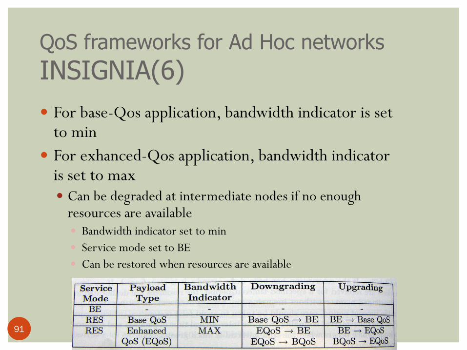
The INSIGNIA option field contains the following field
Service mode
Best-effort (BE) or requiring reservation (RES)
payload type
Base-QoS, enhanced QoS
bandwidth indicator
Has Min/Max value to reflect the status of the flow
bandwidth request
90
QoS frameworks for Ad Hoc networks
INSIGNIA(6)
For base-Qos application, bandwidth indicator is set to min
For exhanced-Qos application, bandwidth indicator is set to max Can be degraded at intermediate nodes if no enough
resources are available Bandwidth indicator set to min
Service mode set to BE
Can be restored when resources are available
91
QoS frameworks for Ad Hoc networks
INSIGNIA(7) Releasing Resources
The destination monitors the delivered flow, and measures the QoS, and sends a reports back to source
when source sends an enhanced QoS packet with MAX requirements At non-bottleneck nodes, the resources are reserved as requested At bottleneck nodes, the bandwidth indicator flag are set to MIN So resources are over-allocated at non-bottleneck nodes
When nodes receiving the report from destination they release the extra allocated resources
92
QoS frameworks for Ad Hoc networks
INSIGNIA(8) Route Maintenance
Supports 3 types of flow restoration Immediate restoration
Occurs when a rerouted flow immediately recovers to its original reservation
Degraded restoration
Occurs when a rerouted flow is degraded for a period bfore it recovers to its original reservation
Permanent restoration
Occurs when the rerouted flow never recovers to its original reservation
93

QoS frameworks for Ad Hoc networks
INSIGNIA(9)
Advantages An integrated approach provisioning QoS
Disadvantages Supports only adaptive applications
Multimedia applications
Transparent to MAC protocol
fairness and reservation scheme have a significant influence in provisioning QoS guarantees
Assumes that routing protocol provides new routes when topology changes
The route maintenance mechanism significantly affects the real time traffic
The QoS can be downgraded
No suitable for realtime application
94

QoS frameworks for Ad Hoc networks
INORA Coarse feed back scheme
When a node fails to provide QoS, it sends an admission control failure (ACF) msg. to its upstream node
The upstream reroutes the flow through other nodes If no neighbor can provide the requested QoS, it sends an ACF to
upstream node
When this happens, the packets are sent as best-effort packets from source to destination
123
95

QoS frameworks for Ad Hoc networks
INORA(1)
USE
INSIGNIA in-band signaling mechanism
TORA routing protocol
Coarse Feedback Scheme
Class-based Fine Feedback Scheme
96

QoS frameworks for Ad Hoc networks
INORA(2)
97
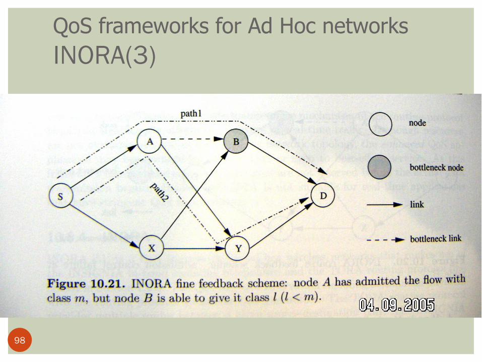
QoS frameworks for Ad Hoc networks
INORA(3)
98

QoS frameworks for Ad Hoc networks
INORA(4)
Advantages
Search multiple paths with lesser QoS guarantees (Compare
with INSIGNIA)
Use the INSIGNIA in-band signaling mechanism
Disadvantages
May not be suitable for applications that require hard service
guarantees
Because of the failure flow may only service as BE
99

QoS frameworks for Ad Hoc networks
SWAN(1) Stateless wireless ad hoc network
Assimes a best-effort MAC protocol
Uses feedback-based control mechanisms to support real-time
services and service differentiation
Uses local rate control, a source-based admission control, an
explicit congestion notification (ECN)
Unlike INSIGNIA and INORA, intermediate nodes don’t have
to maitaining the per-flow state information
100

QoS frameworks for Ad Hoc networks
SWAN(2)
101

QoS frameworks for Ad Hoc networks
SWAN(3) Local rate control of BE traffic
Assumes most traffic are BE
Uses the bandwidth left out by real time traffic
Traffic rate controller determines the departure rate of the traffic using AIMD (additive increase multiplicative decrease) algorithm Every T secs, tx rate = tx rate + c (Kbps)
If rx rate exceeds the threshold
tx rate = tx rate * r percent
If shaping rate is greater than g percent of the actual rate
shaping rate is adjusts to be g percent above the actual rate
102

QoS frameworks for Ad Hoc networks
SWAN(4)
Source-Based admission control of real-time traffic The real time traffic should be admitted up to an admission
control rate; the best effort traffic should be allowed to use any remaining bandwidth
Process of admitting a new real time session The source sends a probe packet to estimate the end-to-end bandwidth
Each intermediate nodes update the bottleneck bandwidth field
Admits the real time sessions only if sufficent bandwidth is available
No bandwidth request is in probe packet, and no resource allocation or reservation is done during the lifetime of an admitted session
103

QoS frameworks for Ad Hoc networks
SWAN(4) Routing algorithms
1. Each node continuously estimates the locally available bandwidth 2. When a node detects congestion conditions, it starts marking the ECN bits
in real time packets 3. When destination receives these packets, it sends a regulate msg. back to
source 4. The source re-establish the session based on the original bandwidth
requirements by sending a probe packet to destination
The above approach is not efficient, the SWAN model consider 2 approaches Source-based regulation Network-based regulation
104

QoS frameworks for Ad Hoc networks
SWAN(5) Source-based regulation
The source waits for a random amount of time after receiving a regulate
msg. , then initiates the re-establishment process
Avoid flash-crowd conditions
Network-based regulation
The congested nodes randomly select a congestion set of rt-sessions, and
mark only packets in this set
105

QoS frameworks for Ad Hoc networks
SWAN(6) Advantages
scalable
disadvantages
Can’t provide Hard QoS
In worst case, the admitted rt-traffic can be dropped of live in
BE mode
Don’t perform well when most traffic is real time
106

QoS frameworks for Ad Hoc networks
Proactive RTMAC(1) PRTMAC is a cross layer framework
On-demand QoS extension of DSR routing protocol at layer 3 RTMAC at layer 2
Provides bandwidth availability estimation
Uses an out-of-band signaling channel to gather additional information about the on-going real-time calls A narrow band control channel that operates over a transmission range with
twice that of the data transmission, is used as the out-of-band signaling channel
A greater transmission range than data channel
Mobility affects the real-time traffic in 2 ways Breakaways Reservation clashs
107

QoS frameworks for Ad Hoc networks
Proactive RTMAC(2)
Breakway
clash
108

QoS frameworks for Ad Hoc networks
Proactive RTMAC(3)
Operation of PRTMAC
Every node sends out control beacons
at regular intervals over control
channel
The calls the source node is carrying
Start- and end- time of the real time
call
The slot reservation status
Signal strength is used to estimate the
relative distance between 2 nodes
109

QoS frameworks for Ad Hoc networks
Proactive RTMAC(4) Crossover-time prediction
The time when a node crosses another node’s data transmission range
A node stores number of <time, signal strength> tuples received from other nodes
110

QoS frameworks for Ad Hoc networks
Proactive RTMAC(5)
111

QoS frameworks for Ad Hoc networks
Proactive RTMAC(6) Handling Breakaways
Local reconfiguration When a node’s downstream node is down, the node tries the local reconfiguration
End-to-end reconfiguration Sends a RouteError packet back to source
Combines these two Node C checks if there is a path to F in its routing table
If there is one, C makes the reservation.
When a call is interrupted, and local reconfiguration is tried for a number of times, the end-to-end reconfiguration is attempted
112

QoS frameworks for Ad Hoc networks
Proactive RTMAC(7)
Handling Clashs When clashs happens, the PRTMAC shifts one of the calls to a
new slot
113

QoS frameworks for Ad Hoc networks
Proactive RTMAC(8)
when clash happens,
suppose that N is responsible for reconfig calls
N tries to find a free slot in N and C
By going through its reservation table and its
neighbor’s table corresponding to C
If success
Shifts the call
If failed
Low priority gets dropped, and undergoes an
end-to-end reconfiguration
114

QoS frameworks for Ad Hoc networks
Proactive RTMAC(9)
Diffserv provisioning in PRTMAC
Class 1
Real-time calls
Preempt the law priority calls
Class 2
End-to-end bandwidth reservation
Best-effort
115

QoS frameworks for Ad Hoc networks
Proactive RTMAC(10)
Advantage
Provides better rt-traffic support and service differentiation in
high mobility ad hoc wireless networks
disadvantage
Having another control channel may be a problem in low-power
and resource-constrained environments
116

Transport Layer Issues for QoS
Provisioning TCP performs poorly in terms of end-to-end throughput in
MANETs The assumption used in Internet that packet losses are due to congestion is
not valid in MANET environments
TCP performance improvement in wireless networks: Local retransmissions Split-TCP connections Forward error corrections (FEC)
Explicit feedback mechanisms to distinguish between losses due to errors and congestion is necessary for QoS provisioning in MANETs
Efficient techniques for resource management is necessary for QoS provisioning

Application Layer Issues Application level QoS adaptation belong to adaptive
strategies that play a vital role in supporting QoS Flexible user interfaces, dynamic QoS ranges, adaptive
compression algorithms, joint source-channel coding, joint source-network coding schemes
Adaptive real-time audio/video streaming support can be provided by enhancing: Compression algorithms, layered encoding, rate shaping,
adaptive error control, and bandwidth smoothing

Inter-Layer Design Approaches
Efficient intercommunication protocols need to conserve
scarce resources – something difficult to achieve following
the strict separation of the protocol layer functionalities
Inter-layer or cross-layer issues needs to be examined
Examples: INSIGNIA and iMAQ

Outline Introduction
Issues and challenges in providing QoS in Ad hoc wireless networks
Classifications of QoS solutions
MAC layer solutions
Network layer solutions
QoS frameworks for Ad Hoc wireless networks
summary
120

Summary
The issues and challenges in providing QoS
Classfication of QoS
MAC/ network layer solution
frameworks
121