Lecture 22. Inductance. Magnetic Field Energy. Inductance Magnetic field...Lecture 22. Inductance....
16
Lecture 22. Inductance. Magnetic Field Energy. Outline: Self-induction and self-inductance. Inductance of a solenoid. The energy of a magnetic field. Alternative definition of inductance. Mutual Inductance. 1
Transcript of Lecture 22. Inductance. Magnetic Field Energy. Inductance Magnetic field...Lecture 22. Inductance....
Lecture 22. Inductance. Magnetic Field Energy.
Outline:
Self-induction and self-inductance.
Inductance of a solenoid.
The energy of a magnetic field.
Alternative definition of inductance.
Mutual Inductance.
1
Energy Transformations in EM Waves and Circuits
2
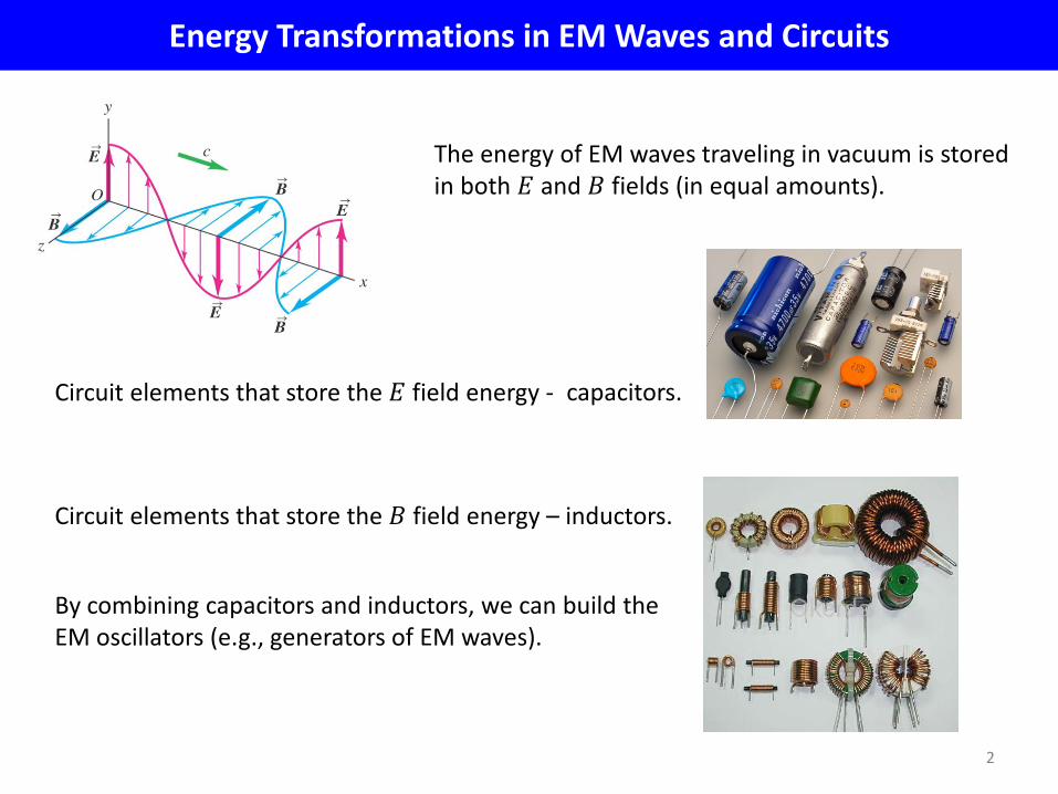
The energy of EM waves traveling in vacuum is stored in both 𝐸 and 𝐵 fields (in equal amounts).
Circuit elements that store the 𝐸 field energy - capacitors.
Circuit elements that store the 𝐵 field energy – inductors.
By combining capacitors and inductors, we can build the EM oscillators (e.g., generators of EM waves).
Maxwell’s Equations
� 𝐸 ∙ 𝑑𝑙𝑙𝑜𝑜𝑜
= −𝑑𝑑𝑑� 𝐵 ∙ 𝑑𝐴
𝑠𝑢𝑢𝑢
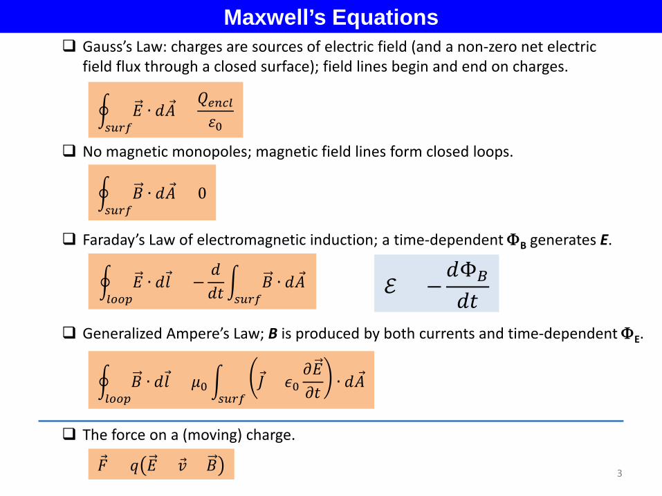
Faraday’s Law of electromagnetic induction; a time-dependent ΦB generates E.
� 𝐵 ∙ 𝑑𝑙𝑙𝑜𝑜𝑜
= 𝜇0 � 𝐽 + 𝜖0𝜕𝐸𝜕𝑑 ∙ 𝑑𝐴
𝑠𝑢𝑢𝑢
Generalized Ampere’s Law; B is produced by both currents and time-dependent ΦE.
�⃗� = 𝑞 𝐸 + �⃗� × 𝐵
The force on a (moving) charge.
3
Gauss’s Law: charges are sources of electric field (and a non-zero net electric field flux through a closed surface); field lines begin and end on charges.
No magnetic monopoles; magnetic field lines form closed loops.
� 𝐸 ∙ 𝑑𝐴𝑠𝑢𝑢𝑢
=𝑄𝑒𝑒𝑒𝑙𝜀0
� 𝐵 ∙ 𝑑𝐴𝑠𝑢𝑢𝑢
= 0
ℰ = −𝑑Φ𝐵
𝑑𝑑
Induced E.M.F. and its consequences
8
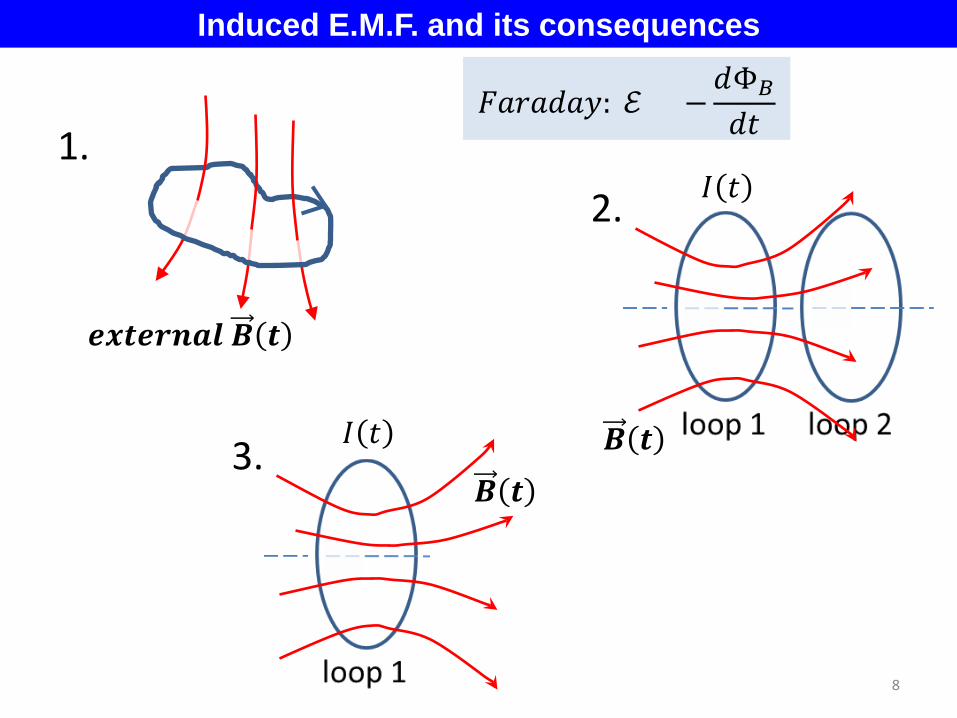
𝒆𝒆𝒆𝒆𝒆𝒆𝒆𝒆 𝑩 𝒆
𝐹𝐹𝐹𝐹𝑑𝐹𝐹: ℰ = −𝑑Φ𝐵
𝑑𝑑
1. 2.
3. 𝑩 𝒆
𝐼 𝑑
𝐼 𝑑
𝑩 𝒆
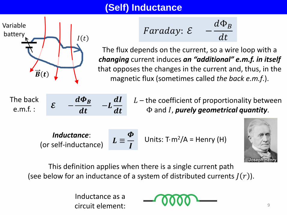
(Self) Inductance
The flux depends on the current, so a wire loop with a changing current induces an “additional” e.m.f. in itself that opposes the changes in the current and, thus, in the
magnetic flux (sometimes called the back e.m.f.).
Inductance: (or self-inductance)
This definition applies when there is a single current path (see below for an inductance of a system of distributed currents 𝐽 𝐹 ).
𝑳 ≡𝜱𝑰
9
𝑩 𝒆
𝐼 𝑑
Variable battery
𝐿 – the coefficient of proportionality between Φ and 𝐼, purely geometrical quantity. 𝓔 = −
𝒅𝜱𝑩
𝒅𝒆= −𝑳
𝒅𝑰𝒅𝒆
Units: T⋅m2/A = Henry (H)
The back e.m.f. :
Inductance as a circuit element:
𝐹𝐹𝐹𝐹𝑑𝐹𝐹: ℰ = −𝑑Φ𝐵
𝑑𝑑

Inductance of a Long Solenoid
The magnetic flux generated by current 𝐼:
𝐿 =Φ𝐵
𝐼=𝜇0𝑁2
l 𝜋𝐹2 = 𝜇0𝑛2l 𝜋𝐹2
l
(n – the number of turns per unit length)
10
Long solenoid of radius r and length l with the total number of turns 𝑁:
𝐿 ≡Φ𝐵
𝐼
Φ𝐵 = 𝐵𝜋𝐹2𝑁 = 𝐵 = 𝜇0𝑁l𝐼 =
𝜇0𝑁2𝐼l
𝜋𝐹2 = 𝜇0𝑛2𝐼 l 𝜋𝐹2
- the inductance scales with the solenoid volume l 𝜋𝐹2; - the inductance scales as N2: B is proportional to 𝑁l and the net flux ∝ N.
Let’s plug some numbers: l =0.1m, N=100, r=0.01m
𝐿 = 𝜇0𝑛2l 𝜋𝐹2 = 4𝜋 ∙ 10−7 ∙1000.1
2
∙ 0.1 ∙ 𝜋 0.01 2 ≈ 40𝜇𝜇
How significant is the induced e.m.f.? For 𝑑𝑑𝑑𝑑
~104𝐴/𝑠 (let’s say, ∆𝐼~ 10 mA in 1 µs) ℰ = 𝐿
𝑑𝐼𝑑𝑑 =
4 ∙ 10−5 𝜇 × 1 ∙ 104𝐴𝑠 = 0.4𝑉
Note that
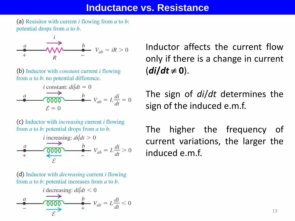
Inductance vs. Resistance
13
Inductor affects the current flow only if there is a change in current (di/dt ≠ 0). The sign of di/dt determines the sign of the induced e.m.f. The higher the frequency of current variations, the larger the induced e.m.f.

Energy of Magnetic Field To increase a current in a solenoid, we have to do some work: we work against the back e.m.f.
𝑈 = �𝑃 𝑑 𝑑𝑑𝑢
𝑖
= �𝐿𝐿 ∙ 𝑑𝐿𝑑
0
=12 𝐿𝐼
2
V Let’s ramp up the current from 0 to the final value 𝐼
(𝐿 𝑑 is the instantaneous current value):
𝑉 𝑑 = 𝐿𝑑𝐿 𝑑𝑑𝑑 𝑃 𝑑 = 𝑉 𝑑 𝐿 𝑑 = 𝐿
𝑑𝐿 𝑑𝑑𝑑 𝐿 𝑑
P(power) - the rate at which energy is being delivered to the inductor from external sources.
The net work to ramp up the current from 0 to 𝐼 :
𝐿 𝑑
𝐿 𝑑 𝑑𝑈 = 𝑃 𝑑 𝑑𝑑
This energy is stored in the magnetic field created by the current.
𝐿 = 𝜇0𝑛2l 𝜋𝐹2 = 𝜇0𝑛2 ∙ 𝑣𝑣𝑙𝑣𝑣𝑣
𝑈𝐵 =12 𝜇0𝑛
2 𝑣𝑣𝑙𝑣𝑣𝑣 ∙ 𝐼2= 𝐵 = 𝜇0𝑛𝐼 =𝐵2
2𝜇0∙ 𝑣𝑣𝑙𝑣𝑣𝑣 = 𝑣𝐵 ∙ 𝑣𝑣𝑙𝑣𝑣𝑣
The energy density in a magnetic field:
14
𝒖𝑩 =𝑩𝟐
𝟐𝝁𝟎 (compare with 𝑣𝐸 = 𝜀0𝐸2
2 )
This is a general result (not solenoid-specific).
𝑼 =𝟏𝟐𝑳𝑰𝟐

Quench of a Superconducting Solenoid
MRI scanner: the magnetic field up to 3T within a volume ~ 1 m3. The magnetic field energy:
Magnet quench: http://www.youtube.com/watch?v=tKj39eWFs10&feature=related
𝑈 = 𝑣𝑣𝑙𝑣𝑣𝑣 ∙ 𝑣𝐵 = 1𝑣3 3𝑇 2
2 ∙ 4𝜋 ∙ 10−7 𝑊𝑊𝐴 ∙ 𝑣
≈ 4𝑀𝐽
The heat of vaporization of liquid helium: 3 kJ/liter. Thus, ~ 1000 liters will be evaporated during the quench.
The capacity of the LHe dewar: ~2,000 liters.
15
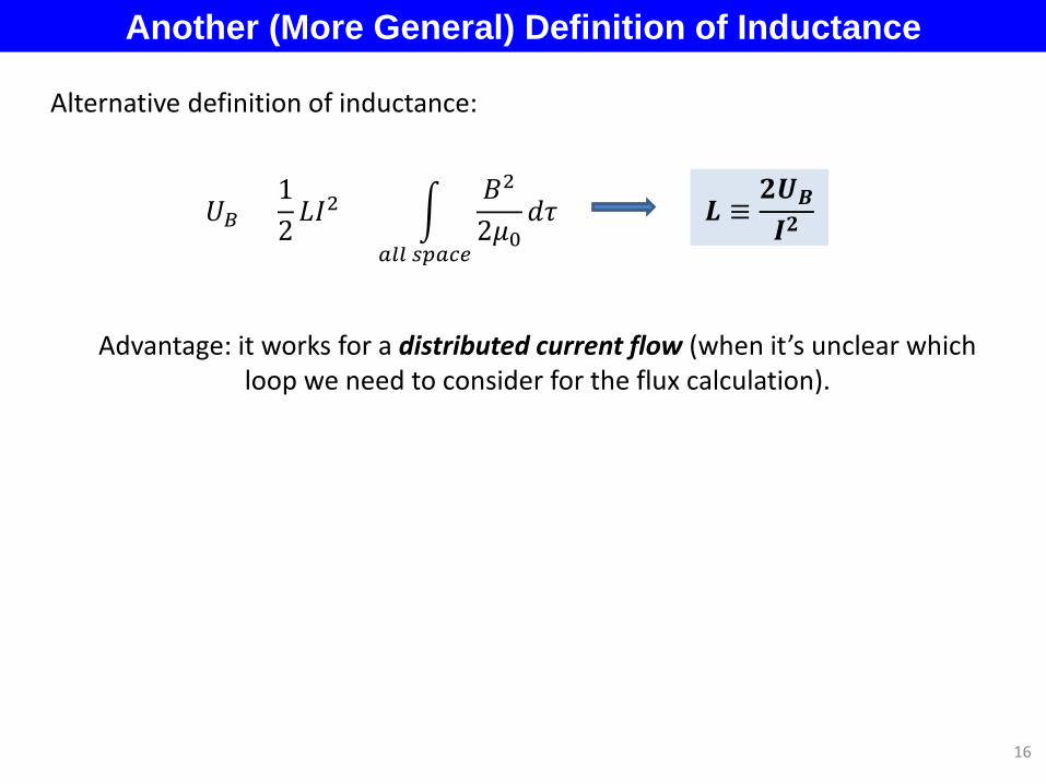
Another (More General) Definition of Inductance
16
𝑈𝐵 =12𝐿𝐼2 = �
𝐵2
2𝜇0𝑑𝜏
𝑎𝑙𝑙 𝑠𝑜𝑎𝑒𝑒
Advantage: it works for a distributed current flow (when it’s unclear which loop we need to consider for the flux calculation).
𝑳 ≡𝟐𝑼𝑩𝑰𝟐
Alternative definition of inductance:

Example: inductance per unit length for a coaxial cable
17
Uniform current density in the central conductor of radius a:
𝑈𝐵 =1
2𝜇0� 𝐵 𝐹 2𝑑𝜏𝑏
0
𝐵 𝐹 =
𝜇0𝐼2𝜋𝐹
, 𝐹 < 𝐹 < 𝑊
𝜇0𝐼𝐹2𝜋𝐹2
, 𝐹 < 𝐹
Straight Wires: Do They Have Inductance?
𝐼
𝐼
𝐹 𝑊
𝐿 =2𝑈𝐵𝐼2
Using 𝑳 = 𝜱/𝑰: 𝐿 𝜇 ≈
𝜇02𝜋 l ∙ 𝑙𝑛
l𝐹 ≈ 2 ∙ 10−7l 𝑣 ∙ 𝑙𝑛
l𝐹
l = 1𝑐𝑣 𝐿 ≈ 10−9𝜇
𝑈𝐵 =1
2𝜇0�
𝜇0𝐼2𝜋𝐹
2𝑑𝜏
𝑏
𝑎
=1
2𝜇0�
𝜇0𝐼2𝜋𝐹
2∙ l ∙ 2𝜋𝐹𝑑𝐹
𝑏
𝑎
≈ (𝑊~l ) ≈𝜇0𝐼2
4𝜋∙ l ∙ 𝑙𝑛
l𝐹
l
~l 𝐵 ≈𝜇0𝐼2𝜋𝐹 Φ ≈ l�
𝜇0𝐼2𝜋𝐹 𝑑𝐹
l
𝑎
=𝝁𝟎𝑰𝟐𝝅 ∙ l ∙ 𝒆𝒆
l𝒆
𝑳 𝑯 ≈𝝁𝟎𝟐𝝅
l ∙ 𝒆𝒆l𝒆
at home
Using 𝑳 = 𝟐𝑼𝑩/𝑰𝟐:
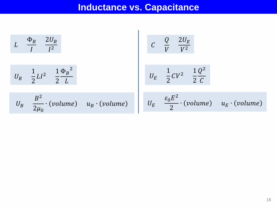
Inductance vs. Capacitance
𝑈𝐵 =𝐵2
2𝜇0∙ 𝑣𝑣𝑙𝑣𝑣𝑣 = 𝑣𝐵 ∙ 𝑣𝑣𝑙𝑣𝑣𝑣
𝐿 =Φ𝐵𝐼 =
2𝑈𝐵𝐼2
𝑈𝐵 =12𝐿𝐼2 =
12Φ𝐵
2
𝐿
𝐶 =𝑄𝑉
=2𝑈𝐸𝑉2
𝑈𝐸 =12𝐶𝑉2 =
12𝑄2
𝐶
𝑈𝐸 =𝜀0𝐸2
2 ∙ 𝑣𝑣𝑙𝑣𝑣𝑣 = 𝑣𝐸 ∙ 𝑣𝑣𝑙𝑣𝑣𝑣
18
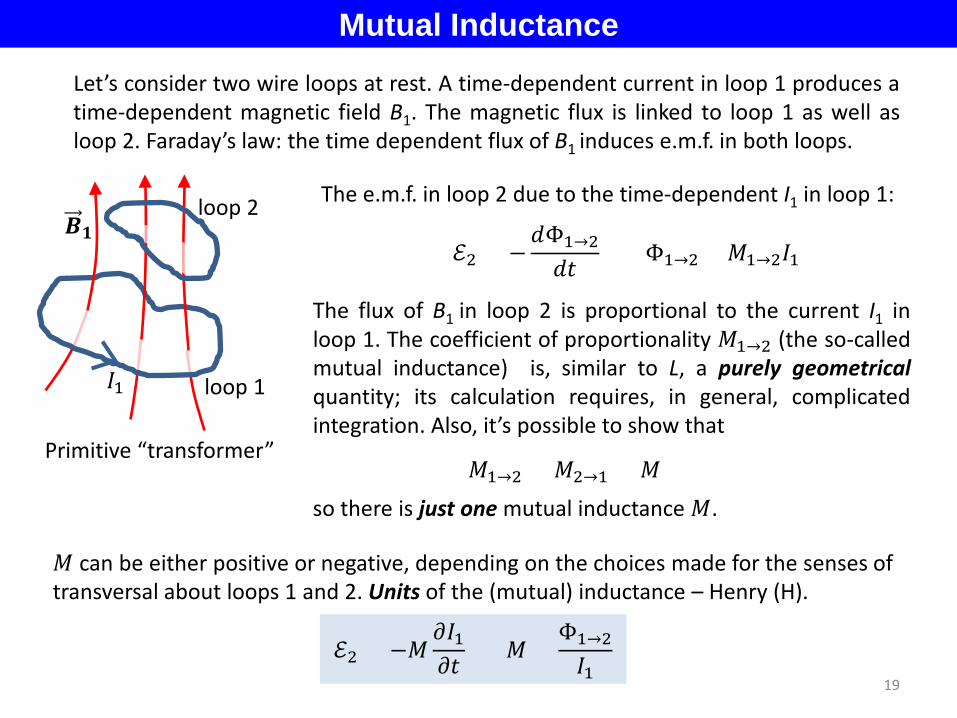
Mutual Inductance Let’s consider two wire loops at rest. A time-dependent current in loop 1 produces a time-dependent magnetic field B1. The magnetic flux is linked to loop 1 as well as loop 2. Faraday’s law: the time dependent flux of B1 induces e.m.f. in both loops.
ℰ2 = −𝑑Φ1→2𝑑𝑑 Φ1→2 = 𝑀1→2𝐼1
𝑩𝟏
loop 1 𝐼1
loop 2
Primitive “transformer”
The e.m.f. in loop 2 due to the time-dependent I1 in loop 1:
The flux of B1 in loop 2 is proportional to the current I1 in loop 1. The coefficient of proportionality 𝑀1→2 (the so-called mutual inductance) is, similar to L, a purely geometrical quantity; its calculation requires, in general, complicated integration. Also, it’s possible to show that
𝑀1→2 = 𝑀2→1 = 𝑀
so there is just one mutual inductance 𝑀.
ℰ2 = −𝑀𝜕𝐼1𝜕𝑑 𝑀 =
Φ1→2𝐼1
𝑀 can be either positive or negative, depending on the choices made for the senses of transversal about loops 1 and 2. Units of the (mutual) inductance – Henry (H).
19
Calculation of Mutual Inductance
20
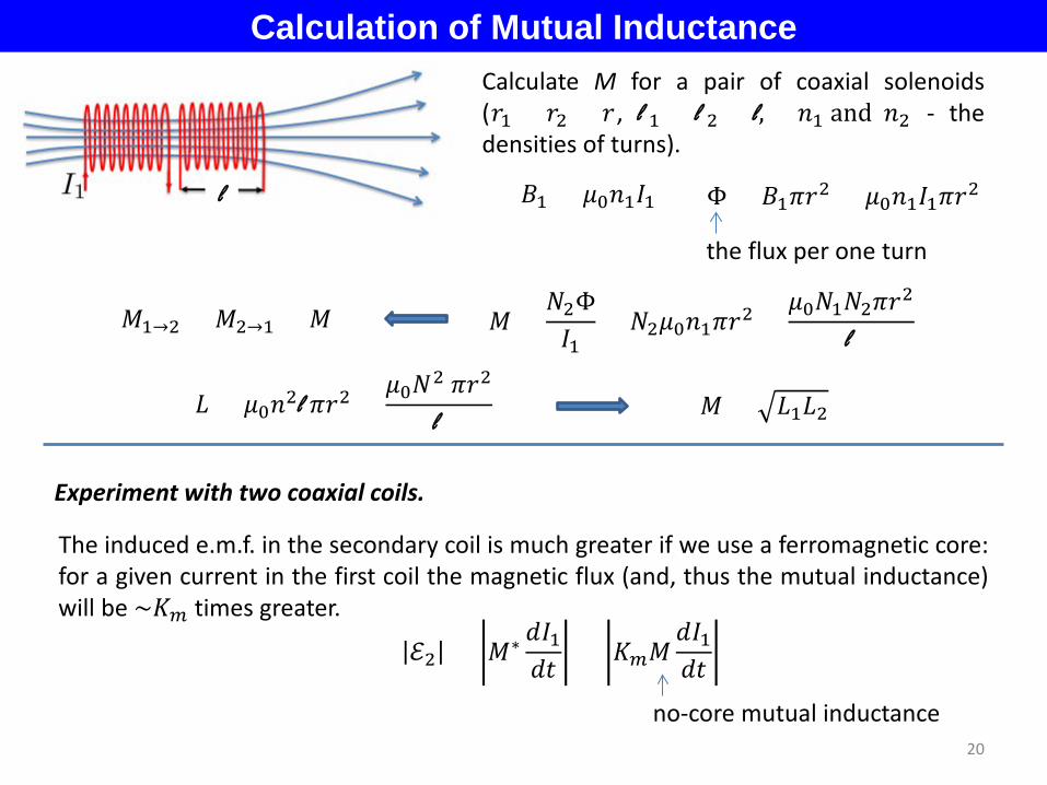
Calculate M for a pair of coaxial solenoids (𝐹1 = 𝐹2 = 𝐹, l 1 = l 2 = l, 𝑛1 and 𝑛2 - the densities of turns).
𝐵1 = 𝜇0𝑛1𝐼1 Φ = 𝐵1𝜋𝐹2 = 𝜇0𝑛1𝐼1𝜋𝐹2
𝑀 =𝑁2Φ𝐼1
= 𝑁2𝜇0𝑛1𝜋𝐹2 =𝜇0𝑁1𝑁2𝜋𝐹2
l
the flux per one turn
l
𝑀1→2 = 𝑀2→1 = 𝑀
𝐿 = 𝜇0𝑛2l 𝜋𝐹2 =𝜇0𝑁2 𝜋𝐹2
l 𝑀 = 𝐿1𝐿2
Experiment with two coaxial coils.
The induced e.m.f. in the secondary coil is much greater if we use a ferromagnetic core: for a given current in the first coil the magnetic flux (and, thus the mutual inductance) will be ~𝐾𝑚 times greater.
ℰ2 = 𝑀∗ 𝑑𝐼1𝑑𝑑 = 𝐾𝑚𝑀
𝑑𝐼1𝑑𝑑
no-core mutual inductance

21
Next time: Lecture 23. RL and LC circuits. §§ 30.4 - 6
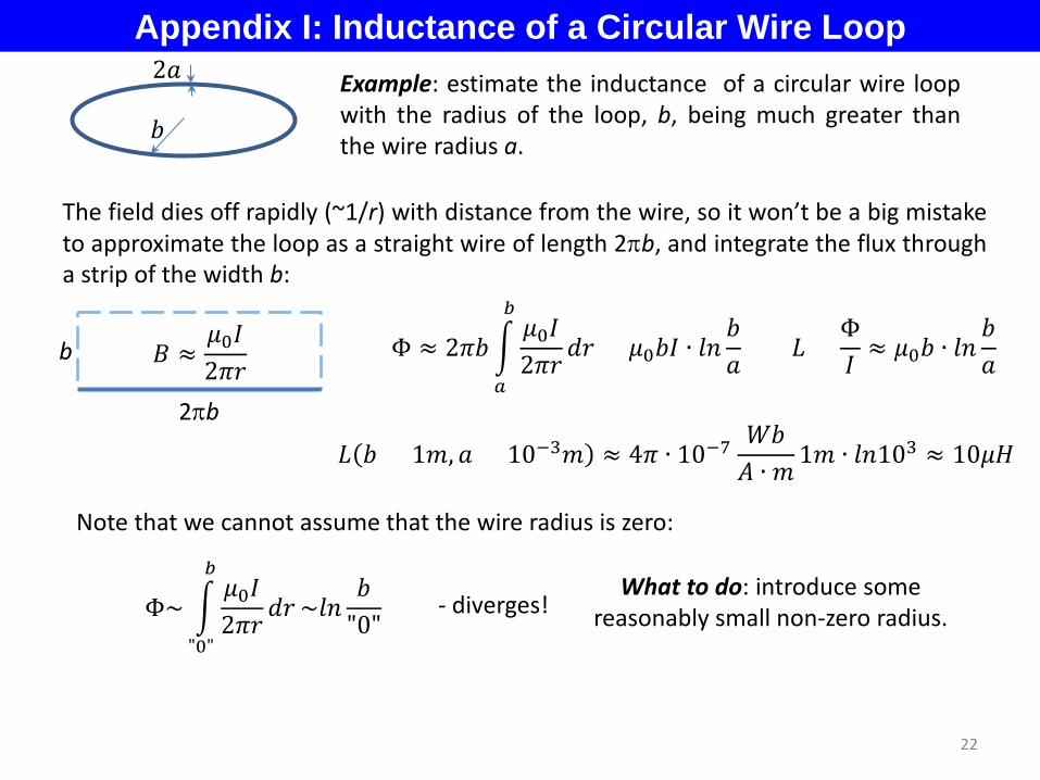
Appendix I: Inductance of a Circular Wire Loop
Note that we cannot assume that the wire radius is zero:
- diverges! Φ~ �𝜇0𝐼2𝜋𝐹 𝑑𝐹
𝑏
"0"
~𝑙𝑛𝑊
"0" What to do: introduce some
reasonably small non-zero radius.
Example: estimate the inductance of a circular wire loop with the radius of the loop, b, being much greater than the wire radius a. 𝑊
2𝐹
The field dies off rapidly (~1/r) with distance from the wire, so it won’t be a big mistake to approximate the loop as a straight wire of length 2πb, and integrate the flux through a strip of the width b:
2πb
b 𝐵 ≈𝜇0𝐼2𝜋𝐹
Φ ≈ 2𝜋𝑊 �𝜇0𝐼2𝜋𝐹
𝑑𝐹𝑏
𝑎
= 𝜇0𝑊𝐼 ∙ 𝑙𝑛𝑊𝐹
𝐿 =Φ𝐼≈ 𝜇0𝑊 ∙ 𝑙𝑛
𝑊𝐹
𝐿 𝑊 = 1𝑣, 𝐹 = 10−3𝑣 ≈ 4𝜋 ∙ 10−7𝑊𝑊𝐴 ∙ 𝑣 1𝑣 ∙ 𝑙𝑛103 ≈ 10𝜇𝜇
22