Lecture 19: Interrupt Basics - Kettering University · Lecture 19: Interrupt Basics. Today’s...
17
Lecture 19: Interrupt Basics
Transcript of Lecture 19: Interrupt Basics - Kettering University · Lecture 19: Interrupt Basics. Today’s...

Lecture 19:Interrupt Basics
Today’s Goals
• Understand fundamental concepts of interrupts.
• Learn about components of an interrupt-capable device.
• Understand general principles of interrupt driven programs.
• Learn how an interrupt is processed by hardware.

What is an Interrupt?
• An event that requires the CPU to stop the current program execution and perform some service related to the event.
• A simple analogy
– Reading a book and the phone rings
– Stop reading and get the phone
– Talk..
– Return to the book where one read and resume to read
• The phone call is an interrupt and the talk is an interrupt service routine (ISR) or an interrupt handler.
Definition of the interrupt
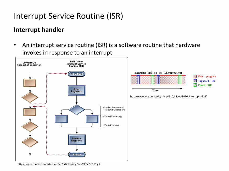
Interrupt Service Routine (ISR)
• An interrupt service routine (ISR) is a software routine that hardware invokes in response to an interrupt
Interrupt handler
http://support.novell.com/techcenter/articles/img/ana1995050101.gif
http://www.ece.unm.edu/~jimp/310/slides/8086_interrupts-9.gif
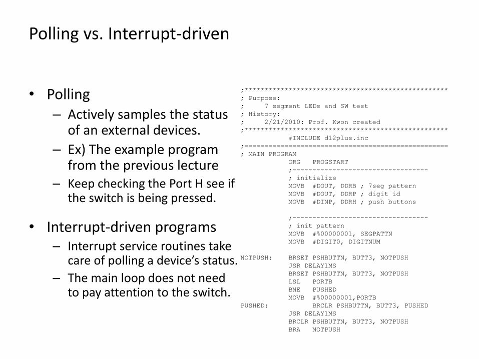
Polling vs. Interrupt-driven
• Polling– Actively samples the status
of an external devices.
– Ex) The example program from the previous lecture
– Keep checking the Port H see if the switch is being pressed.
• Interrupt-driven programs– Interrupt service routines take
care of polling a device’s status.
– The main loop does not need to pay attention to the switch.
;***************************************************
; Purpose:
; 7 segment LEDs and SW test
; History:
; 2/21/2010: Prof. Kwon created
;***************************************************
#INCLUDE d12plus.inc
;===================================================
; MAIN PROGRAM
ORG PROGSTART
;----------------------------------
; initialize
MOVB #DOUT, DDRB ; 7seg pattern
MOVB #DOUT, DDRP ; digit id
MOVB #DINP, DDRH ; push buttons
;----------------------------------
; init pattern
MOVB #%00000001, SEGPATTN
MOVB #DIGIT0, DIGITNUM
NOTPUSH: BRSET PSHBUTTN, BUTT3, NOTPUSH
JSR DELAY1MS
BRSET PSHBUTTN, BUTT3, NOTPUSH
LSL PORTB
BNE PUSHED
MOVB #%00000001,PORTB
PUSHED: BRCLR PSHBUTTN, BUTT3, PUSHED
JSR DELAY1MS
BRCLR PSHBUTTN, BUTT3, NOTPUSH
BRA NOTPUSH

Why are interrupts used?
• Coordinate I/O activities and prevent the CPU from being tied up during data transfer process.
– The CPU needs to know if the I/O is ready before it can proceed. Without the interrupt capability, the CPU needs to check the status of the I/O device continuously.
• Perform time-critical applications.
– Many emergent events require the CPU to take action immediately.
– The interrupt mechanism provides a way to force the CPU to divert from normal program execution and take immediate actions.
Microcomputers I - Electrical and Computer Engineering Dept. at Kettering

Components of an Interrupt-Capable Device
• Cause:
– An event which necessitates the interrupt.
•
– Starting addresses at which the ISR for a particular device begins.
•
– If 0, the microprocessor ignores the device.
•
– When a device needs to be serviced (something happens in the device), a specific bit is to set.
• Configuration:
– Most devices have some options, such as time interval, effects on I/O, etc.
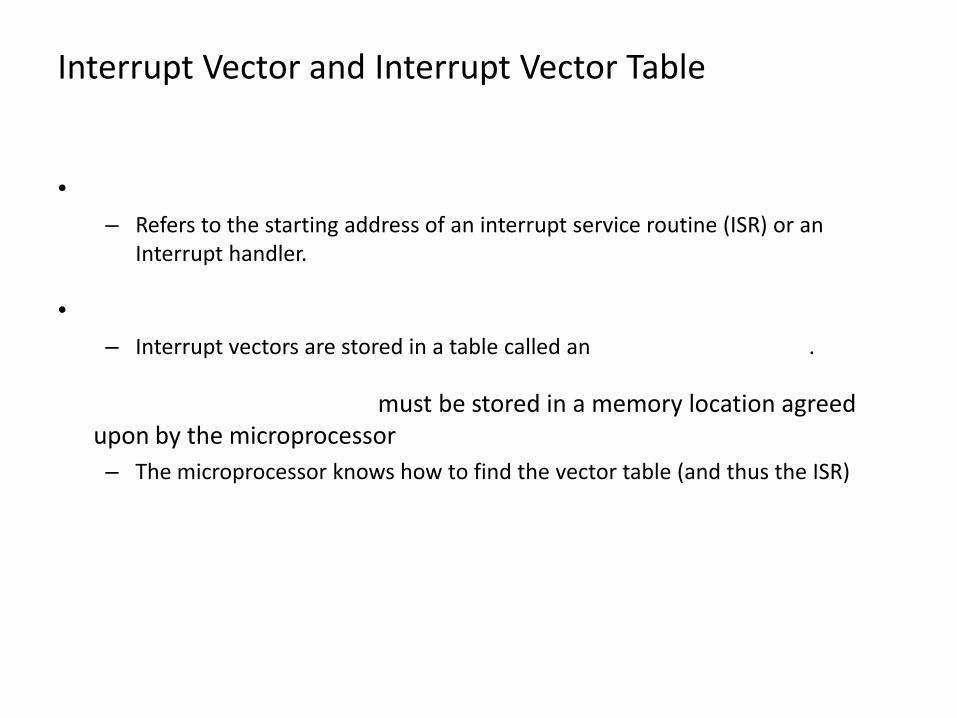
Interrupt Vector and Interrupt Vector Table
•
– Refers to the starting address of an interrupt service routine (ISR) or an Interrupt handler.
•
– Interrupt vectors are stored in a table called an interrupt vector table.
• The interrupt vector table must be stored in a memory location agreed upon by the microprocessor
– The microprocessor knows how to find the vector table (and thus the ISR)
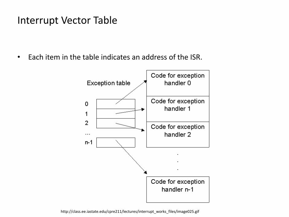
Interrupt Vector Table
• Each item in the table indicates an address of the ISR.
http://class.ee.iastate.edu/cpre211/lectures/interrupt_works_files/image025.gif
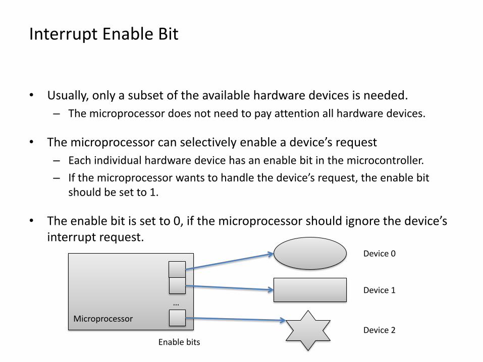
Interrupt Enable Bit
• Usually, only a subset of the available hardware devices is needed.
– The microprocessor does not need to pay attention all hardware devices.
• The microprocessor can selectively enable a device’s request
– Each individual hardware device has an enable bit in the microcontroller.
– If the microprocessor wants to handle the device’s request, the enable bit should be set to 1.
• The enable bit is set to 0, if the microprocessor should ignore the device’s interrupt request.
Microprocessor
…
Enable bits
Device 0
Device 1
Device 2
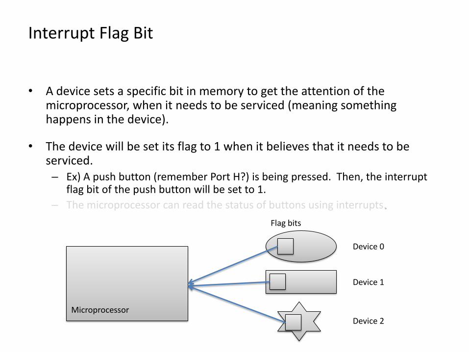
Interrupt Flag Bit
• A device sets a specific bit in memory to get the attention of the microprocessor, when it needs to be serviced (meaning something happens in the device).
• The device will be set its flag to 1 when it believes that it needs to be serviced.– Ex) A push button (remember Port H?) is being pressed. Then, the interrupt
flag bit of the push button will be set to 1.
– The microprocessor can read the status of buttons using interrupts.
Microprocessor
Flag bits
Device 0
Device 1
Device 2

Basic Interrupt Sequence
1. The device that requires service sets its flag bit when an event takes place.
2. The microprocessor detects that a flag is set, verifies that the corresponding enable bit is also set, and triggers an interrupt.
3. The processor status (A, B, X, Y, CC, and PC (return address)) is saved automatically on the stack.
4. The microprocessor looks up the interrupt vector (the address of the ISR) for that device and puts the address into the PC.
5. The microprocessor runs the ISR.
6. At the end of the ISR, RTI must be used.
– RTI is a special form of return instruction which restores the processor status, so that returns to the original program.

When interrupts should be ignored
• There are several situations in which interrupts should not take control.
– 1. During the middle of an instruction
• Since the microprocessor may take several clock cycles to load an instruction, an interrupt could disrupt the fetching of an operation.
– 2. Interrupt another device
• A device should never be able to interrupt another device. This could prevent another ISR from finishing a reasonable amount of time.
• The 68HC12 uses a condition code bit (I bit)
– The I bit is set to 1, the microprocessor will not respond to interrupt requests.
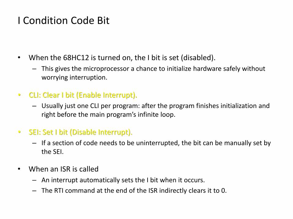
I Condition Code Bit
• When the 68HC12 is turned on, the I bit is set (disabled).
– This gives the microprocessor a chance to initialize hardware safely without worrying interruption.
• CLI: Clear I bit (Enable Interrupt).
– Usually just one CLI per program: after the program finishes initialization and right before the main program’s infinite loop.
• SEI: Set I bit (Disable Interrupt).
– If a section of code needs to be uninterrupted, the bit can be manually set by the SEI.
• When an ISR is called
– An interrupt automatically sets the I bit when it occurs.
– The RTI command at the end of the ISR indirectly clears it to 0.

Timing when the I bit is checked
• To prevent an interrupt from obliterating a partially fetched instruction, the microprocessor only checks for set flags and examines the I bit between instructions.
Wrap-up
• Fundamental concept of Interrupts
• Interrupt-driven vs. polling
• Components of interrupt-capable device
• I condition code bit
What we’ve learned

What to Come
• Interrupt devices
• Real time interrupt
• Example programs