Lecture 1 - Introductionfglima/projeto/aula1t.pdf · Lecture 1 - Introduction • VLSI realization...
28
Lecture 1 - Introduction • VLSI realization process • Verification and test • Ideal and real tests • Roles of testing • Types of Testing • Costs of testing
Transcript of Lecture 1 - Introductionfglima/projeto/aula1t.pdf · Lecture 1 - Introduction • VLSI realization...

Lecture 1 - Introduction
• VLSI realization process
• Verification and test
• Ideal and real tests
• Roles of testing
• Types of Testing
• Costs of testing
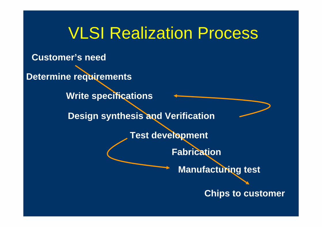
VLSI Realization Process
Determine requirements
Write specifications
Design synthesis and Verification
Fabrication
Manufacturing test
Chips to customer
Customer’s need
Test development
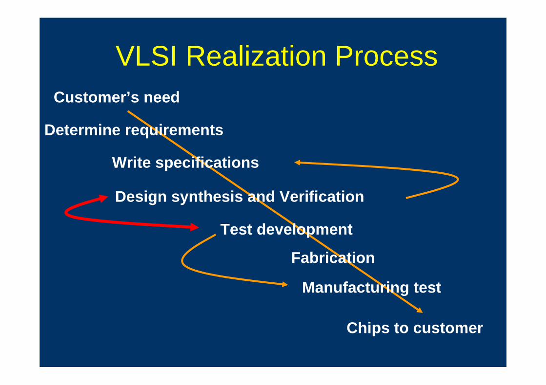
VLSI Realization Process
Determine requirements
Write specifications
Design synthesis and Verification
Fabrication
Manufacturing test
Chips to customer
Customer’s need
Test development

Definitions
• Verification:– Predictive analysis to ensure that the synthesized design,
when manufactured, will perform the given I/O function.
• Test: – A manufacturing step that ensures that the physical
device, manufactured from the synthesized design, has no manufacturing defect.

Verification vs. Test
• Verifies correctness of design.
• Performed by simulation, hardware emulation, or formal methods.
• Performed once prior to manufacturing.
• Responsible for quality of design.
• Verifies correctness of manufactured hardware.
• Two-part process:1. Test generation: software process
executed once during design2. Test application: electrical tests
applied to hardware
• Test application performed on every manufactured device.
• Responsible for quality of devices.

Testing Principle

Problems of Ideal Tests
• Ideal tests detect all defects produced in the manufacturing process.
• Ideal tests pass all functionally good devices.
• Very large numbers and varieties of possible defects need to be tested.
• Difficult to generate tests for some real defects.

Real Tests• Based on analyzable fault models, which may
not map on real defects.
• Incomplete coverage of modeled faults due to high complexity.
• Some good chips are rejected. The fraction (or percentage) of such chips is called the yield loss.
• Some bad chips pass tests. The fraction (or percentage) of bad chips among all passing chips is called the defect level.
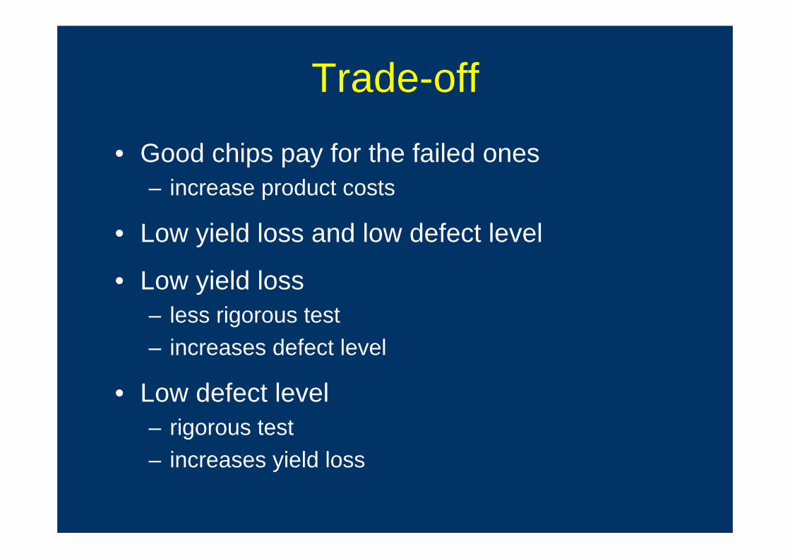
Trade-off
• Good chips pay for the failed ones– increase product costs
• Low yield loss and low defect level
• Low yield loss– less rigorous test– increases defect level
• Low defect level– rigorous test– increases yield loss
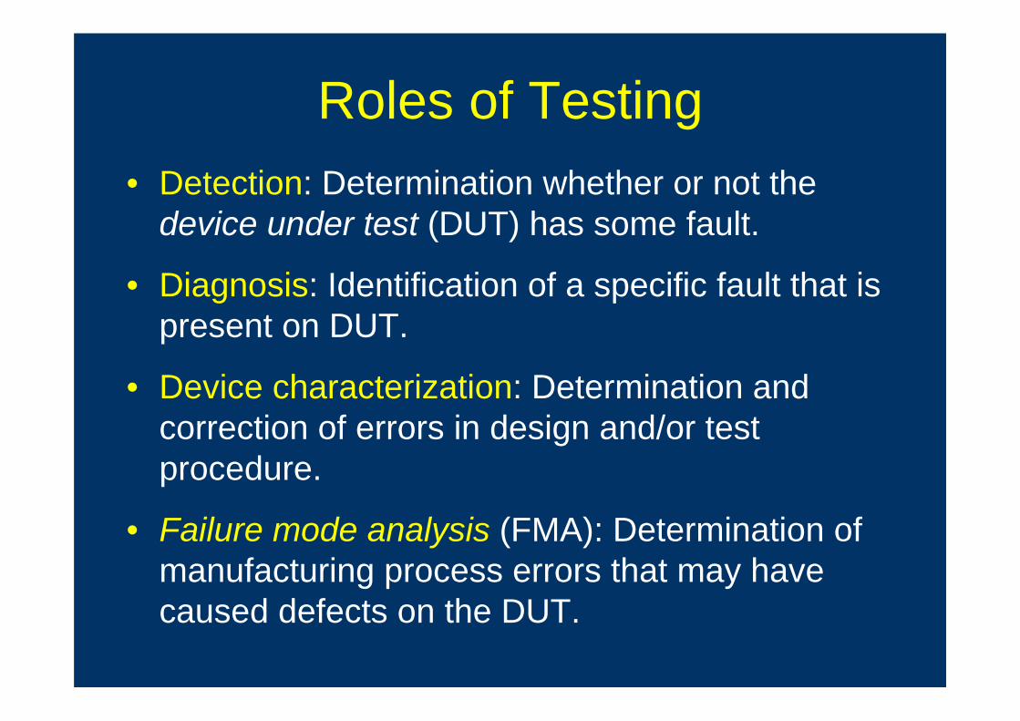
Roles of Testing• Detection: Determination whether or not the
device under test (DUT) has some fault.
• Diagnosis: Identification of a specific fault that is present on DUT.
• Device characterization: Determination and correction of errors in design and/or test procedure.
• Failure mode analysis (FMA): Determination of manufacturing process errors that may have caused defects on the DUT.

Types of Testing
• Verification testing, characterization testing, or design debug– Verifies correctness of design and of test procedure
– usually requires correction to design
• Manufacturing testing– Factory testing of all manufactured chips for
parametric faults and for random defects
• Acceptance testing (incoming inspection)– User (customer) tests purchased parts to ensure
quality
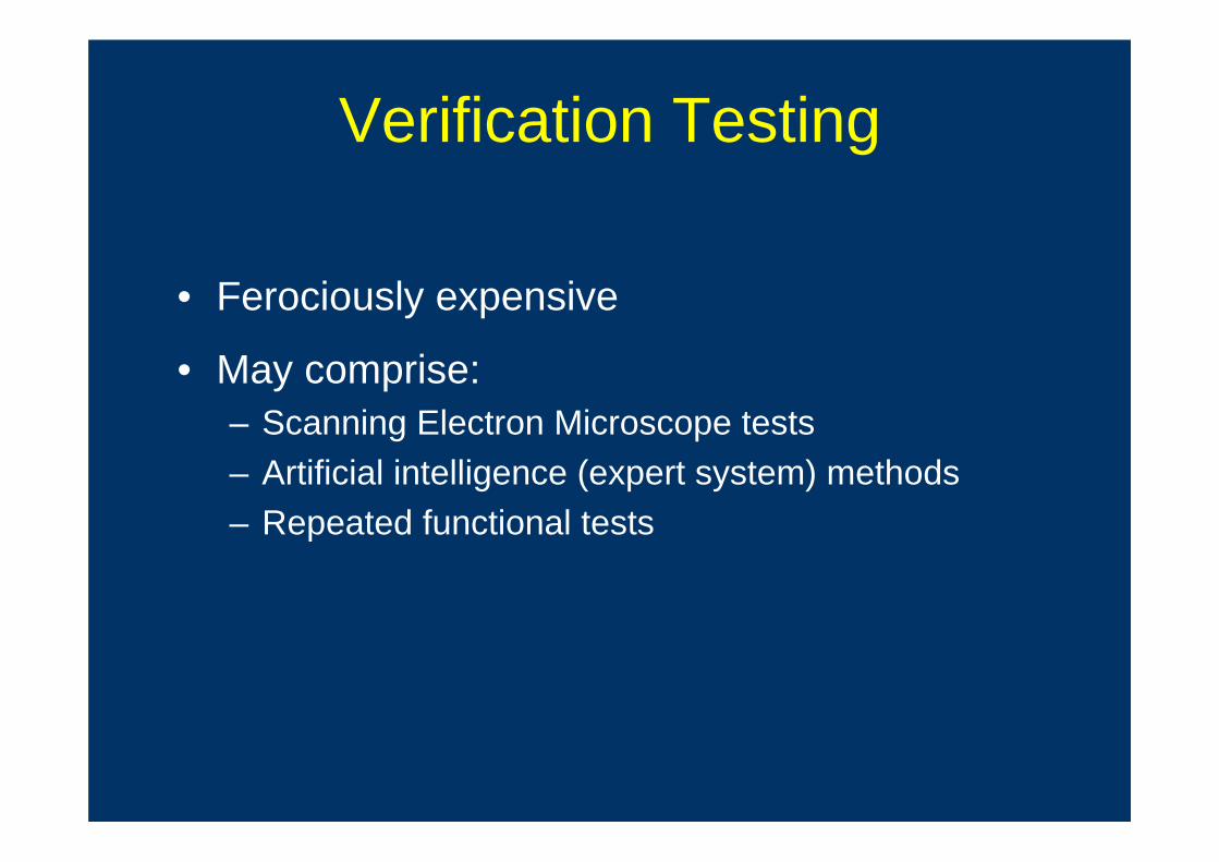
Verification Testing
• Ferociously expensive
• May comprise:– Scanning Electron Microscope tests– Artificial intelligence (expert system) methods– Repeated functional tests
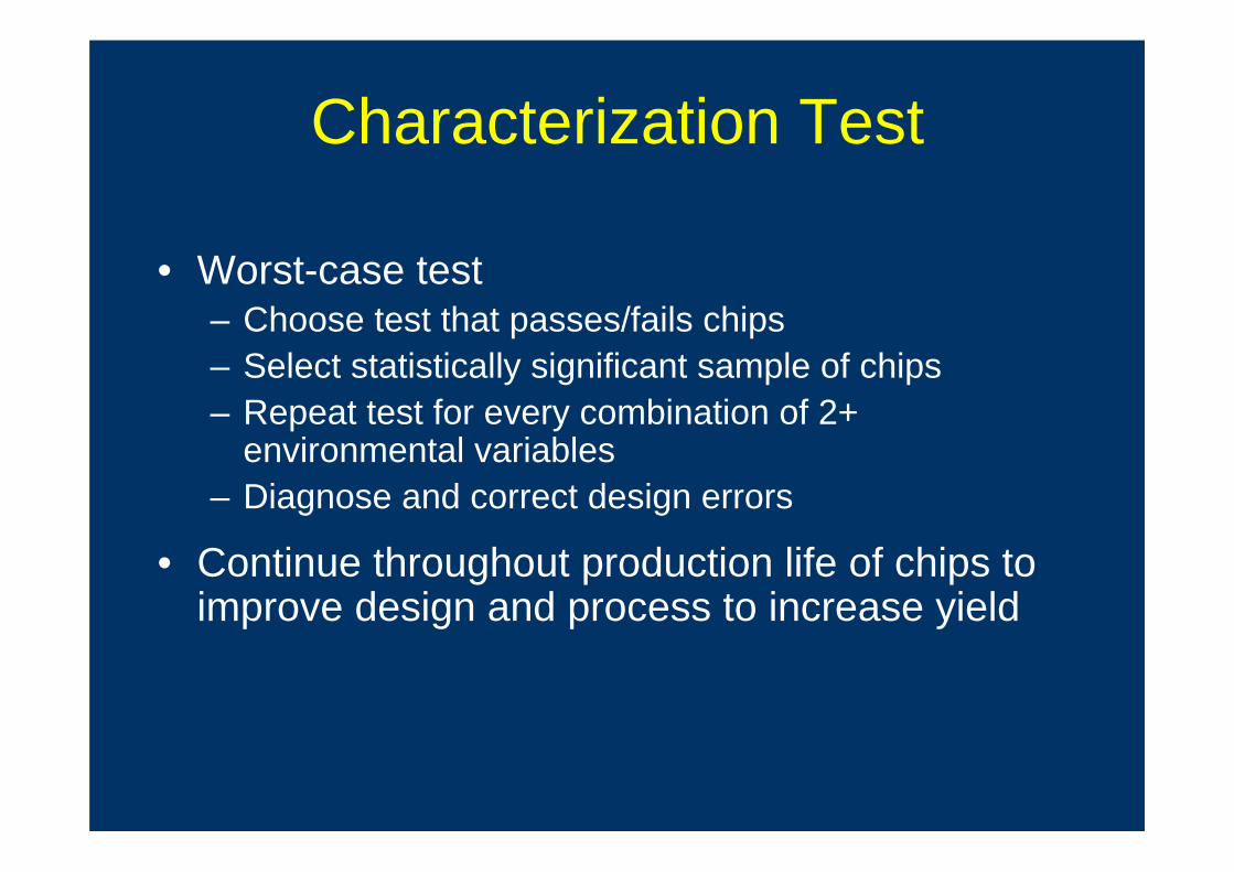
Characterization Test
• Worst-case test– Choose test that passes/fails chips– Select statistically significant sample of chips– Repeat test for every combination of 2+
environmental variables– Diagnose and correct design errors
• Continue throughout production life of chips to improve design and process to increase yield

Incoming Inspection
• Can be:– Similar to production testing– More comprehensive than production testing– Tuned to specific systems application
• Often done for a random sample of devices– Sample size depends on device quality and system
reliability requirements– Avoids putting defective device in a system where
cost of diagnosis exceeds incoming inspection cost

Types of Manufacturing Tests
• Wafer sort or probe test – done before wafer is scribed and cut into chips– Includes test site characterization – specific test
devices are checked with specific patterns to measure the electrical features of transistors
• Packaged device tests

Sub-types of Tests
• Parametric – measures electrical properties of pin electronics – delay, voltages, currents, etc. – fast and cheap
• Functional – used to cover very high % of modeled faults – test every transistor and wire in digital circuits – long and expensive –main topic of course

A Little Bit of History• 1960’s
– Minicomputer controlled ATE systems (Teradyne,GenRad)
• 1970’s– more complex sequential devices– algorithmic test patterns generation
• Late 70’s– in-circuit testing for boards (bed of nails)
• 1980’s– Bed of nails difficult for surface mount devices– requirements for at-speed testing
A Little Bit of History• Late 80’s
– Built-in self tests (BIST)
• 1990’s– current monitoring techniques
• Late 90’s– system-on-chip or core-based test requirements– mixed-signal testing
• 2000’s– test of micro-electro-mechanical structures– network-on-chip based testing

Automatic Test Equipment Components
• Consists of:– Powerful computer
– Powerful Digital Signal Processor (DSP) for analog testing
– Test Program (written in high-level language) running on the computer
– Probe Card (contains electronics to measure signals on chip pin or pad)
– Probe Head or Membrane Probe (actually touches the bare or packaged chip to perform fault detection experiments)
Probe Card and Probe Needles or Membrane
• Probe card – custom printed circuit board (PCB) on which DUT is mounted in socket – may contain custom measurement hardware (current test)
• Probe needles – come down and scratch the pads to stimulate/read pins
• Membrane probe – for unpackaged wafers –contacts printed on flexible membrane, pulled down onto wafer with compressed air to get wiping action

ADVANTEST Model T6682 ATE

T6682 ATE Block Diagram
Parametric test
Comparison of vectors and waveforms
Pins
Test generation
Failed memory words

Pin Electronics
Cost of Testing• Total production cost
– fabrication + packaging + assembly + testing
• fabrication + packaging + assembly– per circuit cost is decreasing
• Testing– cost NOT decreasing
• Test Cost– test equipment cost, test controller, test pattern
generator, interface drivers + receivers, cable and probe contacts, documentation, test personnel

Cost of Manufacturing Testing in 2000AD
• 0.5-1.0GHz, analog instruments,1,024 digital pins: ATE purchase price– = $1.2M + 1,024 x $3,000 = $4.272M
• Running cost (five-year linear depreciation)– = Depreciation + Maintenance + Operation
– = $0.854M + $0.085M + $0.5M– = $1.439M/year
• Test cost (24 hour ATE operation)– = $1.439M/(365 x 24 x 3,600)– = 4.5 cents/second

Cost per chip!
• Tester cost = 4.5 cents/second• ASIC needs 6 seconds to be tested
• ASIC test cost = 27 cents
• If yield = 65% (good chips pay for the bad ones)
• ASIC test cost = 41.5 cents– 41% of a $1.00 chip– 8% of a $5.00 chip
• For a processor: 30s x 4.5 = $1.35 => $2.07 – 50% of a $5.00 (Texas)

Testing Levels and Rule of 10
Circuit
Board
System
Field
1
10
100
1000
Cost/fault ($)

Test Complexity
• CAD tools can help you design an IC in a month - but NOT TESTING!
• Intel 8080 would take over 1020 years at a one million tests per second!
Create adequate tests that run in limited time!