lect8+9+10_notes
24
1 Computer Communications Lectures 8-10 Data Link Layer Required Reading: Tanenbaum (chapter 3), Peterson & Davie (chapter 1) 2 The Data Link Layer • Deals with communication between two neighboring computers over a physical layer that works with raw bit streams • Protocols targeted toward reliable, efficient communication • Need to cope with transmission errors, limited data rate and nonzero propagation delays • Functions: – Provide a well-defined service interface to the network layer – Deal with transmission errors – Regulate the flow of data from sender to receiver
-
Upload
prabhat-singh -
Category
Documents
-
view
214 -
download
2
description
by Prabhat Singh
Transcript of lect8+9+10_notes
1
Computer Communications
Lectures 8-10
Data Link LayerRequired Reading: Tanenbaum (chapter 3), Peterson &
Davie (chapter 1)
2
The Data Link Layer
• Deals with communication between two neighboring computers over a physical layer that works with raw bit streams
• Protocols targeted toward reliable, efficient communication
• Need to cope with transmission errors, limited data rate and nonzero propagation delays
• Functions:– Provide a well-defined service interface to the network layer
– Deal with transmission errors
– Regulate the flow of data from sender to receiver
2
3
Placement of the Data Link Protocol
4
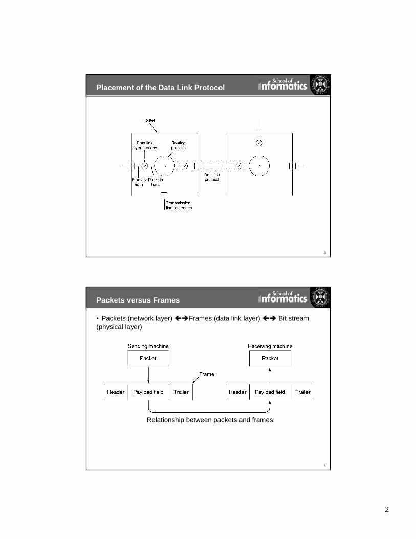
Packets versus Frames
• Packets (network layer) ��Frames (data link layer) �� Bit stream (physical layer)
Relationship between packets and frames.
3
5
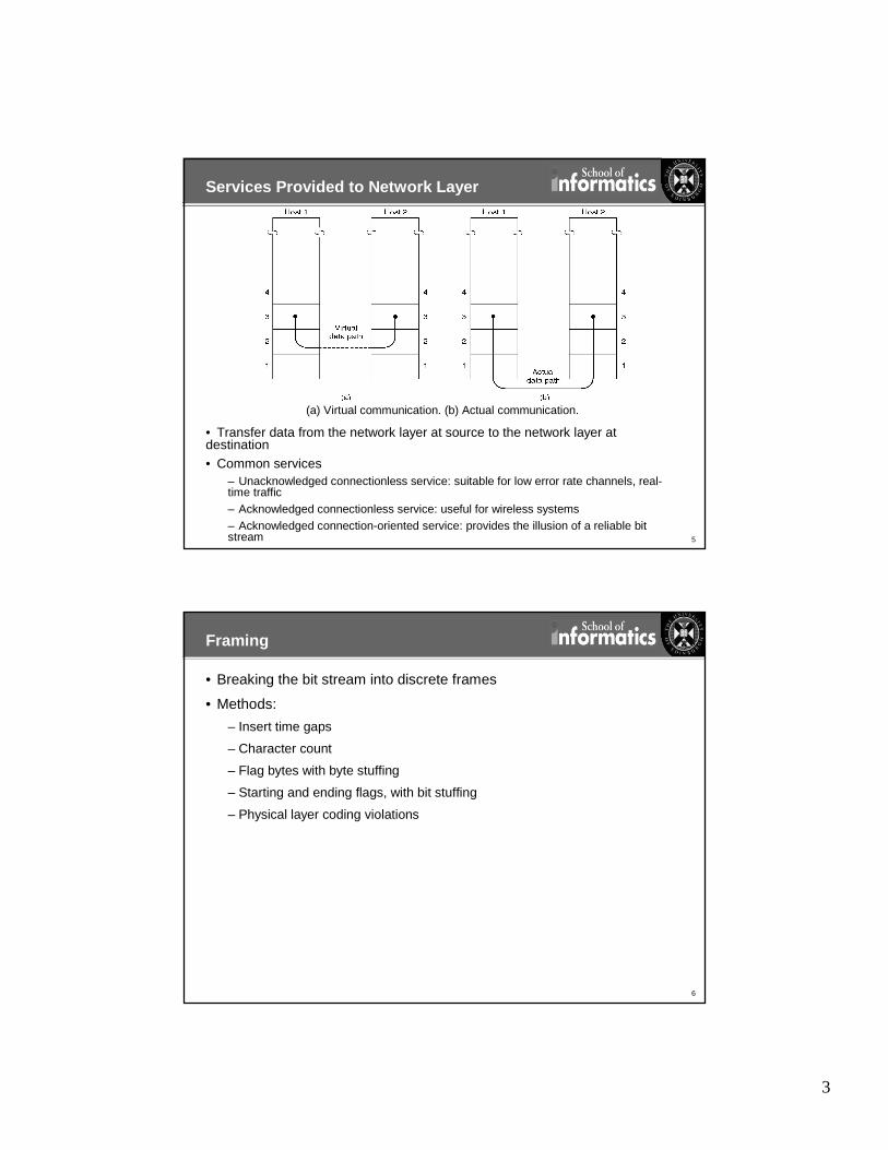
Services Provided to Network Layer
• Transfer data from the network layer at source to the network layer at destination• Common services
– Unacknowledged connectionless service: suitable for low error rate channels, real-time traffic– Acknowledged connectionless service: useful for wireless systems– Acknowledged connection-oriented service: provides the illusion of a reliable bit stream
(a) Virtual communication. (b) Actual communication.
6
Framing
• Breaking the bit stream into discrete frames
• Methods:
– Insert time gaps
– Character count
– Flag bytes with byte stuffing
– Starting and ending flags, with bit stuffing
– Physical layer coding violations

4
7
Framing using Character Count Method
A character stream. (a) Without errors. (b) With one error.
8
Framing using Flag Bytes with Byte Stuffing
(a) A frame delimited by flag bytes.
(b) Four examples of byte sequences before and after stuffing.
5
9
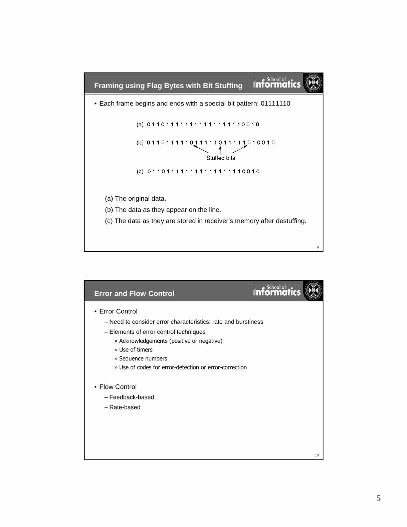
Framing using Flag Bytes with Bit Stuffing
• Each frame begins and ends with a special bit pattern: 01111110
(a) The original data.
(b) The data as they appear on the line.
(c) The data as they are stored in receiver’s memory after destuffing.
10
Error and Flow Control
• Error Control
– Need to consider error characteristics: rate and burstiness
– Elements of error control techniques
» Acknowledgements (positive or negative)
» Use of timers
» Sequence numbers
» Use of codes for error-detection or error-correction
• Flow Control
– Feedback-based
– Rate-based

6
11
Elementary Data Link Protocols
• Assumptions:
– Model of communication: process per layer and message-passing between adjacent layers
– A node (computer) with an infinite supply of data uses reliable, connection-oriented service to send the data to another node over a link (communication channel)
– Computers do not crash
• Three protocols (in increasing order of complexity):
– An Unrestricted Simplex Protocol
– A Simplex Stop-and-Wait Protocol
– A Simplex Protocol for a Noisy Channel
12
Protocol Definitions
Continued �
Some definitions needed in the protocols to follow. These are located in the file protocol.h.

7
13
Protocol Definitions(ctd.)
Some definitions needed in the protocols to follow. These are located in the file protocol.h.
14
Unrestricted Simplex Protocol
• Unidirectional transmission
• Network layers at sender and receiver always ready
• Negligible processing time
• Infinite buffers
• Error-free channel

8
15
Simplex Stop-and-Wait Protocol
• Unidirectional transmission, but half-duplex channel
• Non-negligible processing time
• Finite buffers
• Error-free channel
16
A Simplex Protocol for a Noisy Channel
• Assume that receiver can detect a erroneous frame
• Protocol 2, with addition of timers and sequence numbers
• Size of sequence number: 1 bit (0, 1)
Positive Acknowledgement with Retransmission (PAR) or Automatic Repeat reQuest(ARQ) protocol Continued �

9
17
A Simplex Protocol for a Noisy Channel (ctd.)
Positive Acknowledgement with Retransmission (PAR) or Automatic Repeat reQuest (ARQ) protocol
18
Handling Bidirectional Traffic
• Interleave data and control (e.g., ACK) frames on the same physical circuit
• Piggybacking
10
19
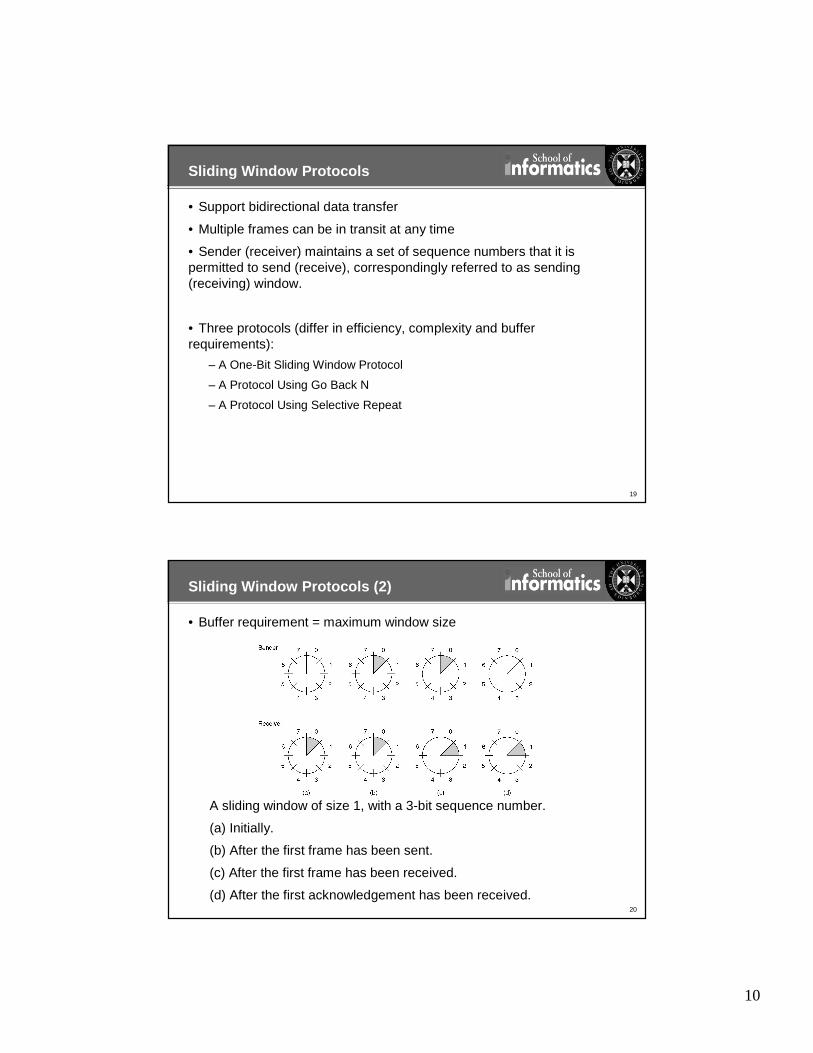
Sliding Window Protocols
• Support bidirectional data transfer
• Multiple frames can be in transit at any time
• Sender (receiver) maintains a set of sequence numbers that it is permitted to send (receive), correspondingly referred to as sending (receiving) window.
• Three protocols (differ in efficiency, complexity and buffer requirements):
– A One-Bit Sliding Window Protocol
– A Protocol Using Go Back N
– A Protocol Using Selective Repeat
20
Sliding Window Protocols (2)
• Buffer requirement = maximum window size
A sliding window of size 1, with a 3-bit sequence number.
(a) Initially.
(b) After the first frame has been sent.
(c) After the first frame has been received.
(d) After the first acknowledgement has been received.

11
21
A One-Bit Sliding Window Protocol
Continued �
22
A One-Bit Sliding Window Protocol (ctd.)

12
23
A One-Bit Sliding Window Protocol (2)
Two scenarios for protocol 4. (a) Normal case. (b) Abnormal case. The notation is (seq, ack, packet number). An asterisk indicates where a network layer accepts a packet.
24
Terminology
• Bandwidth (of channel/link/network/end-to-end)
– Network engineers often use the term “bandwidth”
– Not the same bandwidth in Hz
– Instead in bps, refers to capacity or maximum data rate or maximum bit-rate
– Differentiate with “throughput” – effective data rate
• Latency or delay (of channel/link/network/end-to-end)
– Time to send a message from point A to point B
– One-way versus round-trip time (RTT)
– Components
Latency = Propagation + Transmit + Queue
Propagation = Distance / SpeedOfLight
Transmit = Size / Bandwidth
13
25
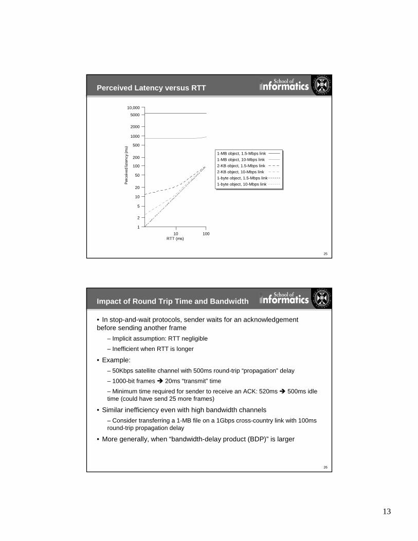
Perceived Latency versus RTT
10,000
5000
2000
1000
500
200
100
50
20
10
5
2
1
10010RTT (ms)
1-MB object, 1.5-Mbps link
1-MB object, 10-Mbps link
2-KB object, 1.5-Mbps link
2-KB object, 10-Mbps link
1-byte object, 1.5-Mbps link
1-byte object, 10-Mbps link
26
Impact of Round Trip Time and Bandwidth
• In stop-and-wait protocols, sender waits for an acknowledgement before sending another frame
– Implicit assumption: RTT negligible
– Inefficient when RTT is longer
• Example:
– 50Kbps satellite channel with 500ms round-trip “propagation” delay
– 1000-bit frames � 20ms “transmit” time
– Minimum time required for sender to receive an ACK: 520ms � 500ms idle time (could have send 25 more frames)
• Similar inefficiency even with high bandwidth channels
– Consider transferring a 1-MB file on a 1Gbps cross-country link with 100ms round-trip propagation delay
• More generally, when “bandwidth-delay product (BDP)” is larger
14
27
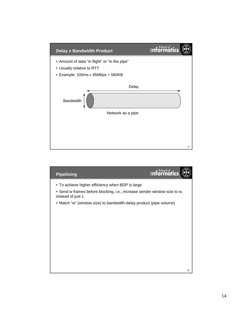
Delay x Bandwidth Product
• Amount of data “in flight” or “in the pipe”
• Usually relative to RTT
• Example: 100ms x 45Mbps = 560KB
Bandwidth
Delay
Network as a pipe
28
Pipelining
• To achieve higher efficiency when BDP is large
• Send w frames before blocking, i.e., increase sender window size to w, instead of just 1
• Match “w” (window size) to bandwidth-delay product (pipe volume)
15
29
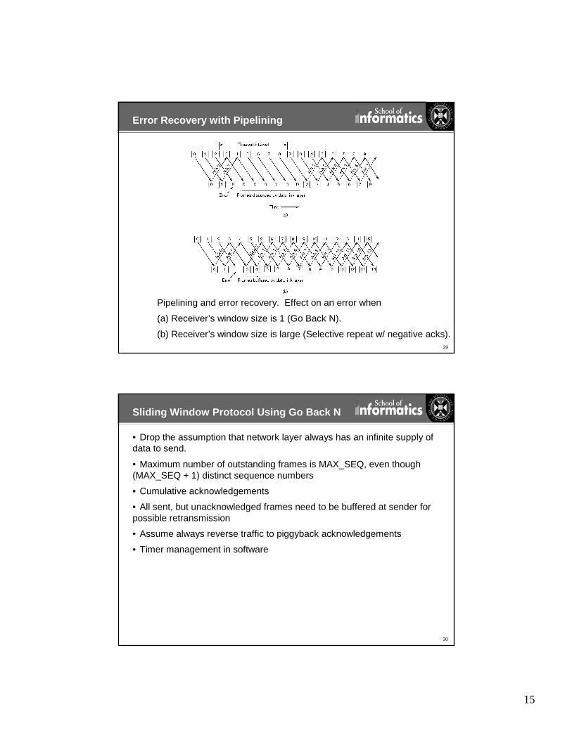
Error Recovery with Pipelining
Pipelining and error recovery. Effect on an error when
(a) Receiver’s window size is 1 (Go Back N).
(b) Receiver’s window size is large (Selective repeat w/ negative acks).
30
Sliding Window Protocol Using Go Back N
• Drop the assumption that network layer always has an infinite supply of data to send.
• Maximum number of outstanding frames is MAX_SEQ, even though (MAX_SEQ + 1) distinct sequence numbers
• Cumulative acknowledgements
• All sent, but unacknowledged frames need to be buffered at sender for possible retransmission
• Assume always reverse traffic to piggyback acknowledgements
• Timer management in software

16
31
Sliding Window Protocol Using Go Back N
Continued �
32
Sliding Window Protocol Using Go Back N
Continued �

17
33
Sliding Window Protocol Using Go Back N
Continued �
34
Sliding Window Protocol Using Go Back N

18
35
Sliding Window Protocol Using Go Back N (2)
Simulation of multiple timers in software.
36
A Sliding Window Protocol Using Selective Repeat
Continued �

19
37
A Sliding Window Protocol Using Selective Repeat (2 )
Continued �
38
A Sliding Window Protocol Using Selective Repeat (3 )
Continued �

20
39
A Sliding Window Protocol Using Selective Repeat (4 )
40
A Sliding Window Protocol Using Selective Repeat (5 )
• Problem: overlap between “new” and “old” receive windows
• Solution: ensure no overlap by limiting the maximum window size to at most half the range of sequence numbers
(a) Initial situation with a window size seven.
(b) After seven frames sent and received, but not acknowledged.
(c) Initial situation with a window size of four.
(d) After four frames sent and received, but not acknowledged.

21
41
A Sliding Window Protocol Using Selective Repeat (6)
• Additional issues:
– #Buffers at receiver = window size
– #Timers = #Buffers
– Use of auxiliary timer at receiver for sending separate ACKs when no reverse traffic to piggyback them
» Length of the timeout?
– Use of negative acknowledgements (NACKs) for “fast” recovery
42
Error Detection and Correction
• Error-Detecting Codes with redundancy sufficient to detect up to a certain number of errors
– When error rates are low, error detection and retransmission is efficient
• Error-Correcting Codes with redundancy needed to also correct a certain number of errors
– Useful when error rate is high
– Lower limit on number of check bits (r) needed for correcting single errors in a message with m bits using the relation (m+r+1) <= 2r
– Achieved using Hamming method
• Codewords, Codes and Hamming Distance (d)
• Need a distance d+1 code to detect d errors– E.g., single parity bit can detect single errors
• Need a distance 2d+1 code to correct d errors– E.g., code (0000000000, 0000011111, 1111100000, 1111111111) can correct double errors

22
43
Hamming Codes
• Can correct single errors
• Can also be used to correct a single “burst” errors via interleaved transmission
– Similar approach also works with parity bits to detect a burst errors
Use of a Hamming code to correct burst errors.
44
Cyclic Redundancy Check (CRC) or Polynomial Code
• Depending on the generator polynomial, polynomial codes can:
– Detect single bit errors
– Detect isolated double errors
– Detect odd number of errors
– Detect all bursts <= r with r check bits
• CRC-32 international standard for IEEE 802
– Detect all bursts <= 32
– Detect all bursts affecting an odd number of bits
• Checksum computation and verification can be done in hardware
Calculation of the polynomial code checksum.
23
45
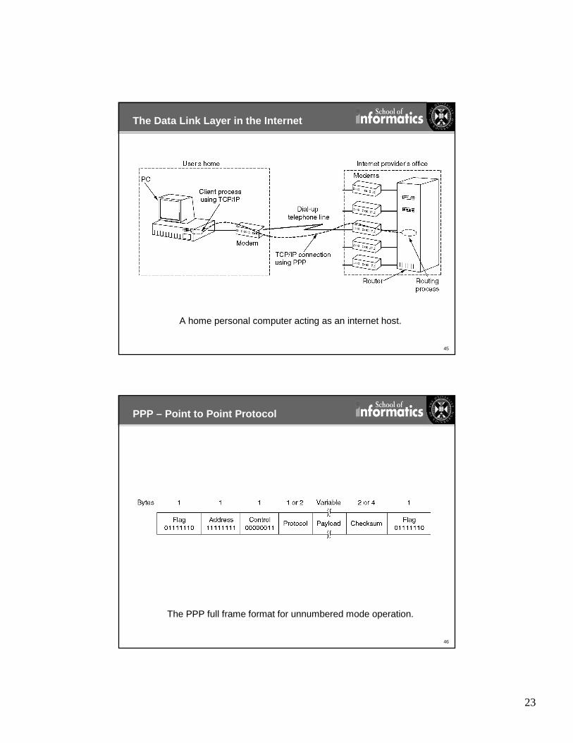
The Data Link Layer in the Internet
A home personal computer acting as an internet host.
46
PPP – Point to Point Protocol
The PPP full frame format for unnumbered mode operation.

24
47
PPP – Point to Point Protocol (2)
A simplified phase diagram for bring a line up and down.
48
PPP – Point to Point Protocol (3)
The LCP frame types.