LeCroy MIL-STD-1553 Datasheetcdn.teledynelecroy.com/files/pdf/lecroy_mil-std-1553_datasheet.pdf ·...
4
MIL-STD-1553 Trigger and Decode Features and Benefits • Correlate analog waveform with protocol decode on one screen • Support for MIL-STD-1553 versions A and B • View decoded data in Binary or Hexadecimal with an intuitive color-coded decode overlay • Decode and trigger on Command, Data, and Status words • Decode and trigger on all 10 message transfer types • Supports triggering for Word, Transfer, and Errors • Portable solution for easy transfer to lab and field testing • Powerful and flexible conditional triggering (=, not =, >, >=, <, <=, in range, out of range) • Decode information expands as the timebase is adjusted or zoomed • Convenient table display with quick “zoom to byte” capability • Quick Search capability for specific message packets The 1553 TD Trigger and Decode package is the ideal tool for system level protocol debug as well as problem solving for signal quality issues. The 1553 TD trigger and decode package adds a unique set of tools to your oscilloscope, simplifying how you design and debug MIL-STD-1553 systems. The powerful internal 1553 TD trigger quickly locates specific transfer or word types and overlays the decoded data directly on top of the physical layer signal. LeCroy’s integration of trigger and data decoding shortens your MIL-STD-1553 debug time. Built-in Oscilloscope Trigger Makes Setup Easy Isolate specific MIL-STD-1553 messages with the built-in oscilloscope trigger. Powerful error triggers identify areas to quickly pinpoint failure locations. Use the conditional address trigger to identify a faulty RT on the bus to reduce debug time. Powerful Conditional Triggering Apply powerful and flexible conditional triggering to completely isolate a specific RT Address, Sub Address Data Value, and Mode Code. The Most Intuitive Decode 1553 TD uses color-coded overlays on various sections of the protocol for an easy-to-understand visual display. Depending on the timebase setting or the amount of zoom, the decode information is condensed or expanded to better assist in understanding events during short or long acquisitions. 1553 TD features both Transfer level and Word level decoding to offer the most flexibility to the debug process. The decode operation is fast—even with long acquisitions. The user can choose to decode into Hex, Binary, ASCII, or Decimal. Color-coded overlays help identify the transfer and word type of the 1553 bus messages. Data values are displayed above the waveform that dynamically change depending on the zoom window.
Transcript of LeCroy MIL-STD-1553 Datasheetcdn.teledynelecroy.com/files/pdf/lecroy_mil-std-1553_datasheet.pdf ·...

MIL-STD-1553Trigger and Decode
Features and Benefits
• Correlate analog waveform with
protocol decode on one screen
• Support for MIL-STD-1553
versions A and B
• View decoded data in Binary or Hexadecimal with an intuitive color-coded decode overlay
• Decode and trigger on Command,
Data, and Status words
• Decode and trigger on all 10
message transfer types
• Supports triggering for Word,
Transfer, and Errors
• Portable solution for easy
transfer to lab and field testing
• Powerful and flexible conditional
triggering (=, not =, >, >=, <, <=,
in range, out of range)
• Decode information expands
as the timebase is adjusted
or zoomed
• Convenient table display with
quick “zoom to byte” capability
• Quick Search capability for
specific message packets
The 1553 TD Trigger and Decode
package is the ideal tool for system
level protocol debug as well as
problem solving for signal quality
issues. The 1553 TD trigger and
decode package adds a unique
set of tools to your oscilloscope,
simplifying how you design and
debug MIL-STD-1553 systems.
The powerful internal 1553 TD trigger
quickly locates specific transfer or
word types and overlays the decoded
data directly on top of the physical
layer signal. LeCroy’s integration of
trigger and data decoding shortens
your MIL-STD-1553 debug time.
Built-in Oscilloscope Trigger Makes Setup EasyIsolate specific MIL-STD-1553
messages with the built-in
oscilloscope trigger. Powerful error
triggers identify areas to quickly
pinpoint failure locations. Use the
conditional address trigger to identify
a faulty RT on the bus to reduce
debug time.
Powerful Conditional TriggeringApply powerful and flexible conditional
triggering to completely isolate a
specific RT Address, Sub Address
Data Value, and Mode Code.
The Most Intuitive Decode1553 TD uses color-coded overlays
on various sections of the protocol for
an easy-to-understand visual display.
Depending on the timebase setting
or the amount of zoom, the decode
information is condensed or expanded
to better assist in understanding
events during short or long acquisitions.
1553 TD features both Transfer level
and Word level decoding to offer the
most flexibility to the debug process.
The decode operation is fast—even
with long acquisitions. The user can
choose to decode into Hex, Binary,
ASCII, or Decimal.
Color-coded overlays help identify the transfer and word type of the 1553 bus messages. Data values are displayed above the waveform that dynamically change depending on the zoom window.
POWErFuL TrIggErIng, InTuITIVE DECODIngPowerful Triggering, inTuiTive DecoDing
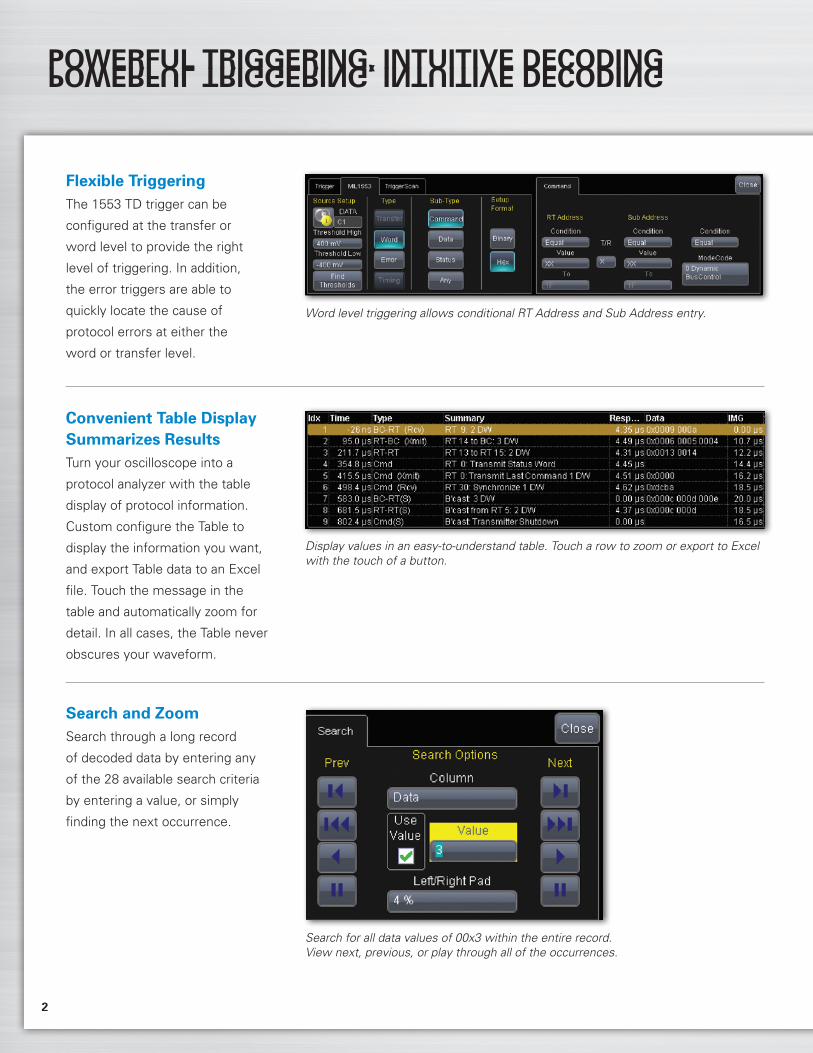
Flexible TriggeringThe 1553 TD trigger can be
configured at the transfer or
word level to provide the right
level of triggering. In addition,
the error triggers are able to
quickly locate the cause of
protocol errors at either the
word or transfer level.
Word level triggering allows conditional RT Address and Sub Address entry.
Convenient Table Display Summarizes resultsTurn your oscilloscope into a
protocol analyzer with the table
display of protocol information.
Custom configure the Table to
display the information you want,
and export Table data to an Excel
file. Touch the message in the
table and automatically zoom for
detail. In all cases, the Table never
obscures your waveform.
Display values in an easy-to-understand table. Touch a row to zoom or export to Excel with the touch of a button.
Search and ZoomSearch through a long record
of decoded data by entering any
of the 28 available search criteria
by entering a value, or simply
finding the next occurrence.
Search for all data values of 00x3 within the entire record. View next, previous, or play through all of the occurrences.
2
SPECIFICATIOnSspecifications
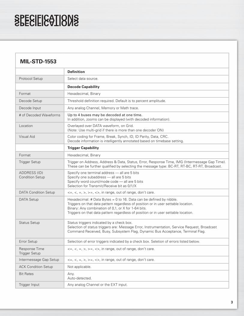
MIL-STD-1553
Definition
Protocol Setup Select data source.
Decode Capability
Format Hexadecimal, Binary
Decode Setup Threshold definition required. Default is to percent amplitude.
Decode Input Any analog Channel, Memory or Math trace.
# of Decoded Waveforms Up to 4 buses may be decoded at one time. In addition, zooms can be displayed (with decoded information).
Location Overlayed over DATA waveform, on Grid. (Note: Use multi-grid if there is more than one decoder ON)
Visual Aid Color coding for Frame, Break, Synch, ID, ID Parity, Data, CRC. Decode information is intelligently annotated based on timebase setting.
Trigger Capability
Format Hexadecimal, Binary
Trigger Setup Trigger on Address, Address & Data, Status, Error, Response Time, IMG (Intermessage Gap Time). These can be further qualified by selecting the message type: BC-RT, RT-BC, RT-RT, Broadcast.
ADDRESS (ID) Condition Setup
Specify one terminal address — all are 5 bitsSpecify one subaddress — all are 5 bitsSpecify word count/mode code — all are 5 bitsSelection for Transmit/Receive bit as 0/1/X
DATA Condition Setup <=, <, =, >, >=, <>, in range, out of range, don’t care.
DATA Setup Hexadecimal: # Data Bytes = 0 to 16. Data can be defined by nibble. Triggers on that data pattern regardless of position or in user settable location.Binary: Any combination of 0,1, or X for 1-64 bits. Triggers on that data pattern regardless of position or in user settable location.
Status Setup Status triggers indicated by a check box.Selection of status triggers are: Message Error, Instrumentation, Service Request, Broadcast Command Received, Busy, Subsystem Flag, Dynamic Bus Acceptance, Terminal Flag.
Error Setup Selection of error triggers indicated by a check box. Seletion of errors listed below.
Response Time Trigger Setup
<=, <, =, >, >=, <>, in range, out of range, don’t care.
Intermessage Gap Setup <=, <, =, >, >=, <>, in range, out of range, don’t care.
ACK Condition Setup Not applicable.
Bit Rates Any. Auto-detected.
Trigger Input Any analog Channel or the EXT input.
3

SPECIFICATIOnS AnD OrDErIng InFOrMATIOnspecifications and ordering information
Ordering InformationProduct Description Product Code
MIL-STD-1553 Trigger and Decode Option WM8Zi-1553 TD for WaveMaster 8 ZiMIL-STD-1553 Trigger and Decode Option WPZi-1553 TD for WavePro 7 ZiMIL-STD-1553 Trigger and Decode Option WRXi-1553 TD for WaveRunner Xi/Xi-A MIL-STD-1553 Trigger and Decode Option WSXs-1553 TD for WaveSurfer Xs/Xs-A
Customer ServiceLeCroy oscilloscopes and probes are designed, built, and tested to ensure high reliability. In the unlikely event you experience difficulties, our digital oscilloscopes are fully warranted for three years and our probes are warranted for one year.
This warranty includes: • No charge for return shipping • Long-term 7-year support • Upgrade to latest software at no charge
1-800-5-LeCroy www.lecroy.com
Local sales offices are located throughout the world.Visit our website to find the most convenient location.
© 2010 by LeCroy Corporation. All rights reserved. Specifications, prices, availability, and delivery subject to change without notice. Product or brand names are trademarks or requested trademarks of their respective holders.
MIL-STD-1553-TD-DS-08Feb10PDF
MIL-STD-1553
Trigger Design Internal to oscilloscope, settable like any other oscilloscope trigger.
Search Capability
Pattern Search Search by Index, Time, Message, Transfer, Type, Summary, Sync, RT Address, Transmit/Receive Flag, Subaddress, Count, Mode Code, Parity, Response Time, RT Address Ack, Message Error, Instrumentation, Service Request Bits, Reserved Bits, Broadcast Received, Busy, Subsystem Flag, Dynamic Bus Control Accepted, Terminal Flag, Data, Intermessage Gap Time, Status, and Attributes Fields.
Other
Compatible With… Fully compatible with WaveMaster® 8 Zi, WavePro® 7 Zi, WaveRunner® Xi/Xi-A, and WaveSurfer® Xs/Xs-A.