lec10 Tribology paper - Indian Institute of Technology Delhiweb.iitd.ac.in/~hirani/lec10.pdf ·...
23
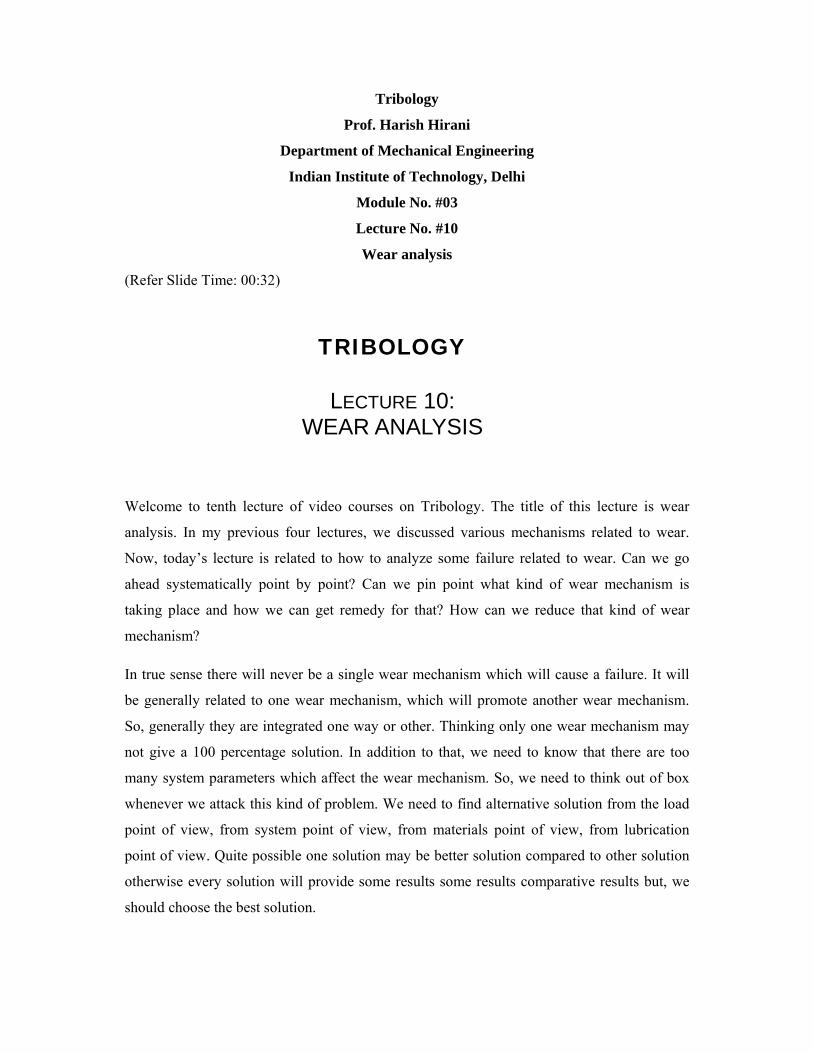
Tribology Prof. Harish Hirani Department of Mechanical Engineering Indian Institute of Technology, Delhi Module No. #03 Lecture No. #10 Wear analysis (Refer Slide Time: 00:32) Welcome to tenth lecture of video courses on Tribology. The title of this lecture is wear analysis. In my previous four lectures, we discussed various mechanisms related to wear. Now, today’s lecture is related to how to analyze some failure related to wear. Can we go ahead systematically point by point? Can we pin point what kind of wear mechanism is taking place and how we can get remedy for that? How can we reduce that kind of wear mechanism? In true sense there will never be a single wear mechanism which will cause a failure. It will be generally related to one wear mechanism, which will promote another wear mechanism. So, generally they are integrated one way or other. Thinking only one wear mechanism may not give a 100 percentage solution. In addition to that, we need to know that there are too many system parameters which affect the wear mechanism. So, we need to think out of box whenever we attack this kind of problem. We need to find alternative solution from the load point of view, from system point of view, from materials point of view, from lubrication point of view. Quite possible one solution may be better solution compared to other solution otherwise every solution will provide some results some results comparative results but, we should choose the best solution. TRIBOLOGY LECTURE 10: WEAR ANALYSIS
Transcript of lec10 Tribology paper - Indian Institute of Technology Delhiweb.iitd.ac.in/~hirani/lec10.pdf ·...
Tribology
Prof. Harish Hirani
Department of Mechanical Engineering
Indian Institute of Technology, Delhi
Module No. #03
Lecture No. #10
Wear analysis
(Refer Slide Time: 00:32)
Welcome to tenth lecture of video courses on Tribology. The title of this lecture is wear
analysis. In my previous four lectures, we discussed various mechanisms related to wear.
Now, today’s lecture is related to how to analyze some failure related to wear. Can we go
ahead systematically point by point? Can we pin point what kind of wear mechanism is
taking place and how we can get remedy for that? How can we reduce that kind of wear
mechanism?
In true sense there will never be a single wear mechanism which will cause a failure. It will
be generally related to one wear mechanism, which will promote another wear mechanism.
So, generally they are integrated one way or other. Thinking only one wear mechanism may
not give a 100 percentage solution. In addition to that, we need to know that there are too
many system parameters which affect the wear mechanism. So, we need to think out of box
whenever we attack this kind of problem. We need to find alternative solution from the load
point of view, from system point of view, from materials point of view, from lubrication
point of view. Quite possible one solution may be better solution compared to other solution
otherwise every solution will provide some results some results comparative results but, we
should choose the best solution.
TRIBOLOGY
LECTURE 10: WEAR ANALYSIS
So, first question comes in our mind can one estimate the wear rate? I believe yes. They have
derived the equation for adhesive wear. We have derived the equation for abrasive wear. We
have derived the equation for erosive wear and fatigue wear also. Using those equations 1 can
estimate wear rate. So, first your answer is yes. We can estimate the wear rate but, professor
Ludema, Michigan University disagrees with that. He says that or I am quoting his sentence
overall it is probably accurate to say that there is a little incentive for a designer to use any of
wear equations available in the literature. What is the reason for that? He proved the reasons
also. He says a scan of many wear models shows considerable intrepidity or inconsistency.
There is some variation from one equation to other equation and people are not coming or
converging to one equation except the orchards model. What are the reasons? The equations
have either too many undefined variables or too few variables or too lesser number of
variables to adequately describe the system. Both the complexity either the system is not been
identified properly or there are too many variables which cannot be determined by few
experiments. You have to do a number of experiments to get the results.
So using directly equations or using wear equations directly may not give complete solutions.
We need to think from other angle. In addition to all this we say most of the available
equations are derived for mild wear rate of the components. What is the meaning of that? At
wear rate if it is on the mild domain mild regime then only can be predicted. In severe wear
case, it cannot be predicted or can say if we are rejecting some component. It is because of
severe wear, because of the high wear rate that is why we are rejecting mild wear. We will
not be rejecting so fast or rejecting severe wear will not be easy for us. If it is a severe wear
then we are rejecting but, we will not diagnose what is the wear mechanism. Severe wear
may come with a number of combinations of wear mechanism.
So finding a root cause failure will be although the difficult situation by using one single
equation. Instead of that we should always go ahead with root level or we start always with
scratch level, try to diagnose what are the forces, how the forces are getting transferred from
one surface to other surface, are they really intentionally they have been transferred or
because of the some system problem, they are getting transferred. So, number of situations is
possible. So, it will be always advisable to go ahead step by step sequentially and try to
analyse if we directly jump see the wear and find out what will be the wear mechanism that
may not give good results.

(Refer Slide Time: 02:00)
Finally, from this slide comes the conclusion that to estimate wear theoretical equations as
well as experimental coefficients are required. That means we cannot get 100 percent results
just by physical relations. We need to have experimental coefficients or experiments
performed on the system to get the results.
We can compare. If we want to compare 2 materials, 4 materials or compare 2 system designs
then wear equations or theoretical equations may give good results. But, we want to find out
absolute sense the life. Then we need to find the need to use experimental coefficient too.
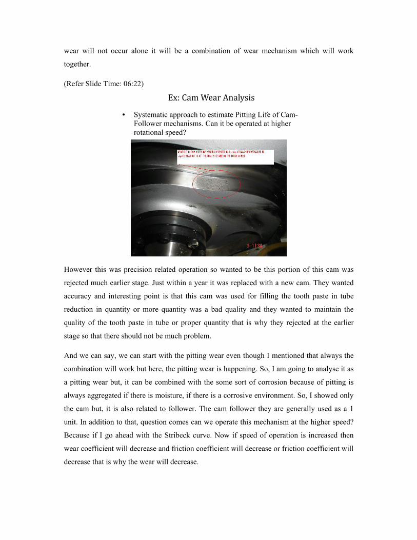
Let us take one example. This slide shows the cam which has some sort of bits over the
surface. This cam was rejected because it was making some noise and it was not performing
its intended function and this portion shows clearly what are the number of bits and if I take
some reference axis as 0 degree here and rotate by 190 rotate by 270 degree; so this kind of
wear occurs roughly 270 degree 270 plus minus some degree.
If I take reference axis over here, then this will turn out to be around 90 degree. That is why
this heading comes this wear has occurred at the 91 degrees. That means there was a
reference axis over here and 91 degree over here if I am assuming the rotational motion is
clockwise. Can we do systematic approach or can we follow systematic approach to estimate
this kind of pitting life of cam follower? Even though in my previous slide I mentioned that
CAN ONE ESTIMATES WEAR RATE?
Yes .. By using Wear Equations
.
• Quoting Ludema’s words [1991] “Overall, it is probably accurate to say that there is
little incentive for a designer to use any of the wear-equations available in the literature.
A scan of many wear models shows considerable incongruity. Equation have either too many undefined variables or too few variables to adequately describe the system”.
Most of available equations are derived/made for mild wear rate of components.
NOTE: To estimate wear Theoretical equations as well as Experimental coefficients are required.
wear will not occur alone it will be a combination of wear mechanism which will work
together.
(Refer Slide Time: 06:22)
However this was precision related operation so wanted to be this portion of this cam was
rejected much earlier stage. Just within a year it was replaced with a new cam. They wanted
accuracy and interesting point is that this cam was used for filling the tooth paste in tube
reduction in quantity or more quantity was a bad quality and they wanted to maintain the
quality of the tooth paste in tube or proper quantity that is why they rejected at the earlier
stage so that there should not be much problem.
And we can say, we can start with the pitting wear even though I mentioned that always the
combination will work but here, the pitting wear is happening. So, I am going to analyse it as
a pitting wear but, it can be combined with the some sort of corrosion because of pitting is
always aggregated if there is moisture, if there is a corrosive environment. So, I showed only
the cam but, it is also related to follower. The cam follower they are generally used as a 1
unit. In addition to that, question comes can we operate this mechanism at the higher speed?
Because if I go ahead with the Stribeck curve. Now if speed of operation is increased then
wear coefficient will decrease and friction coefficient will decrease or friction coefficient will
decrease that is why the wear will decrease.
Ex:CamWearAnalysis • Systematic approach to estimate Pitting Life of Cam-
Follower mechanisms. Can it be operated at higher rotational speed?
So question comes can we really operate at a slightly higher speed compared to what we are
operating? If I assume this cam was operated at 60 RPM can I think about operating at 65
RPM? What will be the benefit of that? Faster filling of the tooth paste will happen with a
higher RPM and if we are able to gain 4-5 percentage production that will help us or that will
overall give the good returns. So, first is that how to analyse this pitting value and second we
can think about increasing the speed without much problem or if speed is going to reduce the
wear, increase the life we should opt for that.
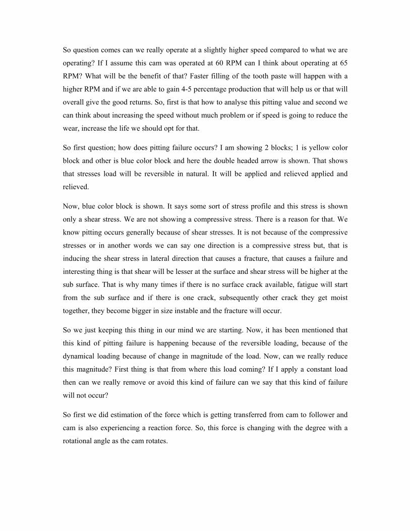
So first question; how does pitting failure occurs? I am showing 2 blocks; 1 is yellow color
block and other is blue color block and here the double headed arrow is shown. That shows
that stresses load will be reversible in natural. It will be applied and relieved applied and
relieved.
Now, blue color block is shown. It says some sort of stress profile and this stress is shown
only a shear stress. We are not showing a compressive stress. There is a reason for that. We
know pitting occurs generally because of shear stresses. It is not because of the compressive
stresses or in another words we can say one direction is a compressive stress but, that is
inducing the shear stress in lateral direction that causes a fracture, that causes a failure and
interesting thing is that shear will be lesser at the surface and shear stress will be higher at the
sub surface. That is why many times if there is no surface crack available, fatigue will start
from the sub surface and if there is one crack, subsequently other crack they get moist
together, they become bigger in size instable and the fracture will occur.
So we just keeping this thing in our mind we are starting. Now, it has been mentioned that
this kind of pitting failure is happening because of the reversible loading, because of the
dynamical loading because of change in magnitude of the load. Now, can we really reduce
this magnitude? First thing is that from where this load coming? If I apply a constant load
then can we really remove or avoid this kind of failure can we say that this kind of failure
will not occur?
So first we did estimation of the force which is getting transferred from cam to follower and
cam is also experiencing a reaction force. So, this force is changing with the degree with a
rotational angle as the cam rotates.
0
500
1000
1500
2000
2500
3000
0 60 120 180 240 300 360
Cam angle, degrees
Nor
mal
load
, N
(Refer Slide Time: 10:07)
It experiences different kind of forces. We can see here the force is roughly twelve 100
Newton steady for some time and then goes down and then goes up at the may be the
maximum value in this cycle is a 90 degree. At the 90 degree the load is high. Again it
remains to a stationary position from roughly 120 degree to 240 degree or 243 degree. It
remains as stationary. It does not change. It is static. After that again it shoots up. It goes on a
higher value crosses compared to this magnitude and the maximum value occurs around 270
degree and then again goes back to the lower value dips and then again rises.
And here what we are referring from the top axis if I go back this is what I am going to say
this axis is at 0 degree rotation and this is 270 degree. Exactly, so whatever we are thinking,
pitting wear has occurred at 270 degree; the same thing is being shown over here the
maximum force is around 2 70 degree. But, I cannot conclude just by finding the force how
much force is generated at the inter phase. We need to do more analysis. One point, one
positive point is that we found the failure at and around 20 270 degree and we found the
failure because of the high load that is the one possibility that high load is there.
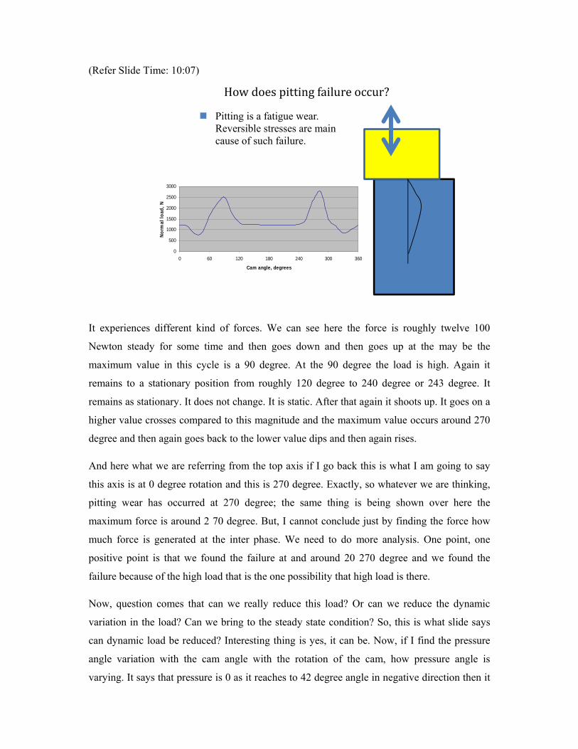
Now, question comes that can we really reduce this load? Or can we reduce the dynamic
variation in the load? Can we bring to the steady state condition? So, this is what slide says
can dynamic load be reduced? Interesting thing is yes, it can be. Now, if I find the pressure
angle variation with the cam angle with the rotation of the cam, how pressure angle is
varying. It says that pressure is 0 as it reaches to 42 degree angle in negative direction then it
Howdoespittingfailureoccur? Pitting is a fatigue wear. Reversible stresses are main cause of such failure.
-50
-40
-30
-20
-10
0
10
20
30
40
50
60
0 60 120 180 240 300 360
Cam angle, degrees
Pre
ssur
e an
gle,
deg
ree
0
500
1000
1500
2000
2500
3000
0 60 120 180 240 300 360
Cam angle, degrees
Norm
al lo
ad, N
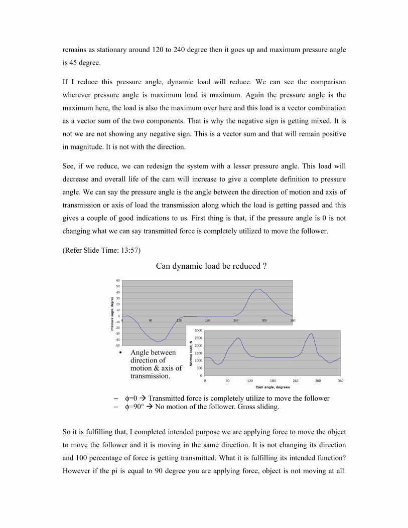
remains as stationary around 120 to 240 degree then it goes up and maximum pressure angle
is 45 degree.
If I reduce this pressure angle, dynamic load will reduce. We can see the comparison
wherever pressure angle is maximum load is maximum. Again the pressure angle is the
maximum here, the load is also the maximum over here and this load is a vector combination
as a vector sum of the two components. That is why the negative sign is getting mixed. It is
not we are not showing any negative sign. This is a vector sum and that will remain positive
in magnitude. It is not with the direction.
See, if we reduce, we can redesign the system with a lesser pressure angle. This load will
decrease and overall life of the cam will increase to give a complete definition to pressure
angle. We can say the pressure angle is the angle between the direction of motion and axis of
transmission or axis of load the transmission along which the load is getting passed and this
gives a couple of good indications to us. First thing is that, if the pressure angle is 0 is not
changing what we can say transmitted force is completely utilized to move the follower.
(Refer Slide Time: 13:57)
So it is fulfilling that, I completed intended purpose we are applying force to move the object
to move the follower and it is moving in the same direction. It is not changing its direction
and 100 percentage of force is getting transmitted. What it is fulfilling its intended function?
However if the pi is equal to 90 degree you are applying force, object is not moving at all.
Can dynamic load be reduced ?
• Angle between direction of motion & axis of transmission.
– φ=0 Transmitted force is completely utilize to move the follower – φ=90° No motion of the follower. Gross sliding.
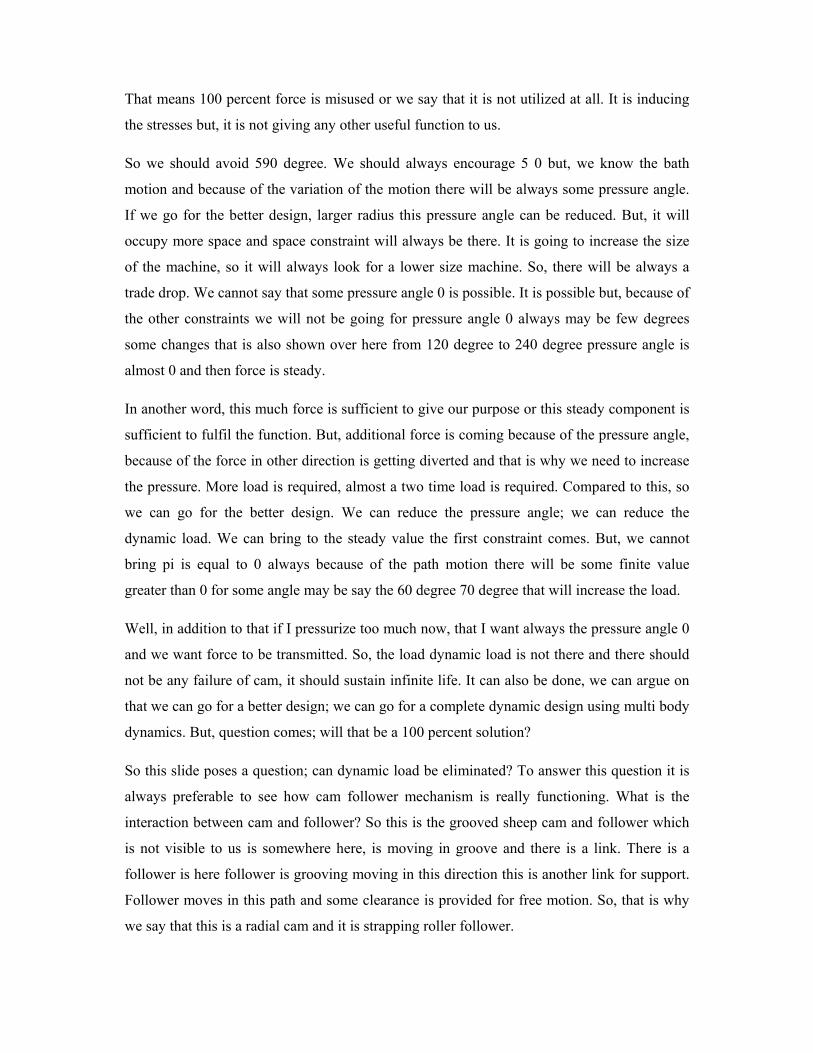
That means 100 percent force is misused or we say that it is not utilized at all. It is inducing
the stresses but, it is not giving any other useful function to us.
So we should avoid 590 degree. We should always encourage 5 0 but, we know the bath
motion and because of the variation of the motion there will be always some pressure angle.
If we go for the better design, larger radius this pressure angle can be reduced. But, it will
occupy more space and space constraint will always be there. It is going to increase the size
of the machine, so it will always look for a lower size machine. So, there will be always a
trade drop. We cannot say that some pressure angle 0 is possible. It is possible but, because of
the other constraints we will not be going for pressure angle 0 always may be few degrees
some changes that is also shown over here from 120 degree to 240 degree pressure angle is
almost 0 and then force is steady.
In another word, this much force is sufficient to give our purpose or this steady component is
sufficient to fulfil the function. But, additional force is coming because of the pressure angle,
because of the force in other direction is getting diverted and that is why we need to increase
the pressure. More load is required, almost a two time load is required. Compared to this, so
we can go for the better design. We can reduce the pressure angle; we can reduce the
dynamic load. We can bring to the steady value the first constraint comes. But, we cannot
bring pi is equal to 0 always because of the path motion there will be some finite value
greater than 0 for some angle may be say the 60 degree 70 degree that will increase the load.
Well, in addition to that if I pressurize too much now, that I want always the pressure angle 0
and we want force to be transmitted. So, the load dynamic load is not there and there should
not be any failure of cam, it should sustain infinite life. It can also be done, we can argue on
that we can go for a better design; we can go for a complete dynamic design using multi body
dynamics. But, question comes; will that be a 100 percent solution?
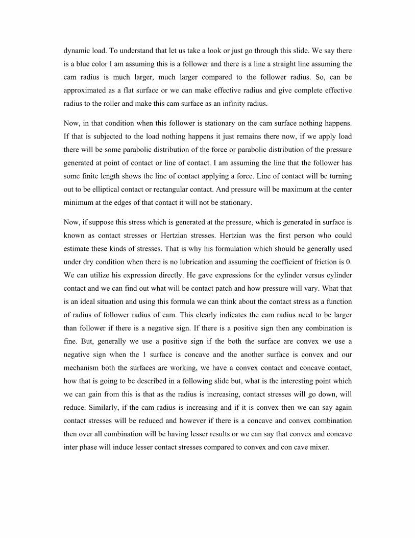
So this slide poses a question; can dynamic load be eliminated? To answer this question it is
always preferable to see how cam follower mechanism is really functioning. What is the
interaction between cam and follower? So this is the grooved sheep cam and follower which
is not visible to us is somewhere here, is moving in groove and there is a link. There is a
follower is here follower is grooving moving in this direction this is another link for support.
Follower moves in this path and some clearance is provided for free motion. So, that is why
we say that this is a radial cam and it is strapping roller follower.

We provide some clearance so that cam can rotate about its own axis. It is rotating about the
cam axis also, instantaneous cam axis but, we want it should freely move about its own axis.
However there will be lot of friction. There will be sliding we want a pure rolling motion.
(Refer Slide Time: 18:58)
We know pure rolling will have will have a lesser coefficient of friction or much lesser
coefficient of friction compared to sliding friction. So, it is always advisable to keep some
clearance that can be decided on how much clearance is just sufficient, which is not creating
any problem of the contact they are not creating any problem of the sliding.
But when we see this kind of mechanism, we understand there is a clearance and we are
allowing roller to rotate about its own axis and it is also rotating about cam axis,
instantaneous cam axis then this point comes the loading and unloading is inherent in rolling
contact or even though we can try pressure angle, we can bring pressure angle to 0 but,
because of this loading and unloading which happens at the rolling contact that is going to
introduce some sort of dynamic load. So, pressure angle making 0 is not going to fulfil the
function. It is not going to give us the desirable results. Even though we do all the claims we
make good mechanism we go ahead with the multi links try to make pressure angle as low as
possible to 0 as close to 0 as possible.
But still in that case because of the rolling contact nature there will be loading and unloading.
That means there will be a force and there will not be force and it will not be generating a
Can dynamic load be Eliminated?
Cam (radial) groove to trap roller follower.
• Cam rotation pushes follower on the shaped geometry. Clearance for free movement of roller follower about its axis. Loading & Unloading is inherent in rolling contact.
dynamic load. To understand that let us take a look or just go through this slide. We say there
is a blue color I am assuming this is a follower and there is a line a straight line assuming the
cam radius is much larger, much larger compared to the follower radius. So, can be
approximated as a flat surface or we can make effective radius and give complete effective
radius to the roller and make this cam surface as an infinity radius.
Now, in that condition when this follower is stationary on the cam surface nothing happens.
If that is subjected to the load nothing happens it just remains there now, if we apply load
there will be some parabolic distribution of the force or parabolic distribution of the pressure
generated at point of contact or line of contact. I am assuming the line that the follower has
some finite length shows the line of contact applying a force. Line of contact will be turning
out to be elliptical contact or rectangular contact. And pressure will be maximum at the center
minimum at the edges of that contact it will not be stationary.
Now, if suppose this stress which is generated at the pressure, which is generated in surface is
known as contact stresses or Hertzian stresses. Hertzian was the first person who could
estimate these kinds of stresses. That is why his formulation which should be generally used
under dry condition when there is no lubrication and assuming the coefficient of friction is 0.
We can utilize his expression directly. He gave expressions for the cylinder versus cylinder
contact and we can find out what will be contact patch and how pressure will vary. What that
is an ideal situation and using this formula we can think about the contact stress as a function
of radius of follower radius of cam. This clearly indicates the cam radius need to be larger
than follower if there is a negative sign. If there is a positive sign then any combination is
fine. But, generally we use a positive sign if the both the surface are convex we use a
negative sign when the 1 surface is concave and the another surface is convex and our
mechanism both the surfaces are working, we have a convex contact and concave contact,
how that is going to be described in a following slide but, what is the interesting point which
we can gain from this is that as the radius is increasing, contact stresses will go down, will
reduce. Similarly, if the cam radius is increasing and if it is convex then we can say again
contact stresses will be reduced and however if there is a concave and convex combination
then over all combination will be having lesser results or we can say that convex and concave
inter phase will induce lesser contact stresses compared to convex and con cave mixer.
That is why we need to think over, do we really going to recommend convex or convex
concave inter phase and as I mentioned that in our case study or cam follower study, both the
combinations are there.
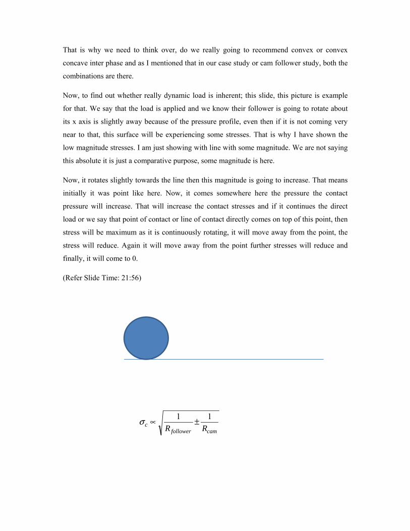
Now, to find out whether really dynamic load is inherent; this slide, this picture is example
for that. We say that the load is applied and we know their follower is going to rotate about
its x axis is slightly away because of the pressure profile, even then if it is not coming very
near to that, this surface will be experiencing some stresses. That is why I have shown the
low magnitude stresses. I am just showing with line with some magnitude. We are not saying
this absolute it is just a comparative purpose, some magnitude is here.
Now, it rotates slightly towards the line then this magnitude is going to increase. That means
initially it was point like here. Now, it comes somewhere here the pressure the contact
pressure will increase. That will increase the contact stresses and if it continues the direct
load or we say that point of contact or line of contact directly comes on top of this point, then
stress will be maximum as it is continuously rotating, it will move away from the point, the
stress will reduce. Again it will move away from the point further stresses will reduce and
finally, it will come to 0.
(Refer Slide Time: 21:56)
camfollowerc RR
11 ±∝σ
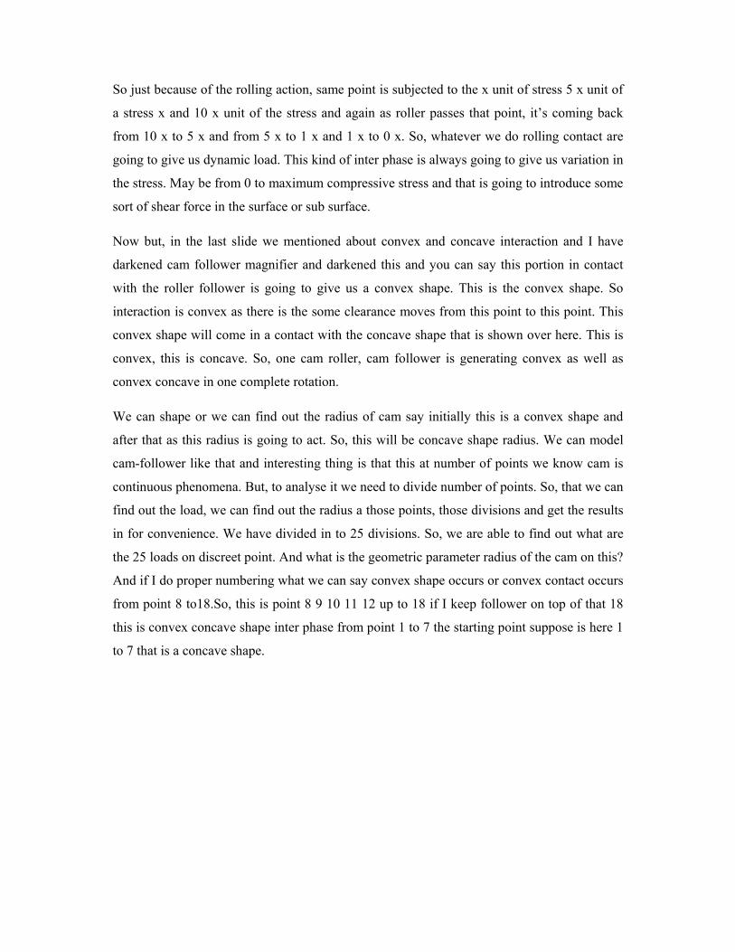
So just because of the rolling action, same point is subjected to the x unit of stress 5 x unit of
a stress x and 10 x unit of the stress and again as roller passes that point, it’s coming back
from 10 x to 5 x and from 5 x to 1 x and 1 x to 0 x. So, whatever we do rolling contact are
going to give us dynamic load. This kind of inter phase is always going to give us variation in
the stress. May be from 0 to maximum compressive stress and that is going to introduce some
sort of shear force in the surface or sub surface.
Now but, in the last slide we mentioned about convex and concave interaction and I have
darkened cam follower magnifier and darkened this and you can say this portion in contact
with the roller follower is going to give us a convex shape. This is the convex shape. So
interaction is convex as there is the some clearance moves from this point to this point. This
convex shape will come in a contact with the concave shape that is shown over here. This is
convex, this is concave. So, one cam roller, cam follower is generating convex as well as
convex concave in one complete rotation.
We can shape or we can find out the radius of cam say initially this is a convex shape and
after that as this radius is going to act. So, this will be concave shape radius. We can model
cam-follower like that and interesting thing is that this at number of points we know cam is
continuous phenomena. But, to analyse it we need to divide number of points. So, that we can
find out the load, we can find out the radius a those points, those divisions and get the results
in for convenience. We have divided in to 25 divisions. So, we are able to find out what are
the 25 loads on discreet point. And what is the geometric parameter radius of the cam on this?
And if I do proper numbering what we can say convex shape occurs or convex contact occurs
from point 8 to18.So, this is point 8 9 10 11 12 up to 18 if I keep follower on top of that 18
this is convex concave shape inter phase from point 1 to 7 the starting point suppose is here 1
to 7 that is a concave shape.
0
20
40
60
80
100
1201
23
4
5
6
7
8
9
10
1112 13 14
15
16
17
18
19
20
21
22
2324
25
(Refer Slide Time: 27:44)
Similarly, 19 to 25 this is a convex shape, concave convex, concave inter phase and
interesting thing is that from 7 to 8 it goes to transition. Similarly, 8 to 18 goes to transition
and this transition is going to introduce sliding, is going to lose rolling motion and most of
the sliding will be getting introduced because of the transformation of the convex to concave.
We say this transition which is introducing sliding and that sliding is reducing the cam life.
So, we should work on this. Can we reduce the sliding if it is possible? That will give us good
results.
So, question comes we have pitted, the sliding is going to reduce the life. Then how sliding is
reduced? Again same figure is shown as in the previous couple of slide figure shows yellow
block subjected to reversible load. Explanation must be given why the load is dynamic and
then the blue block is experiencing some shear strength which is a determinant or it is
creating some problem. It is going to generate some sort of cracks; it is going to generate
some sort of voids in a surface. But, not immediately may be after some cycles. Now, if there
is a sliding introduced then what will happen? We need to have some sort of frictional force
to push it because this force is much larger than rolling friction force.
Convex/Concave Interaction?
• Divide rotational cycle (~ 25 divisions).
• Analyze convex & concave contacts:
– Convex from point 8 to 18.
– Concave from 1 to 7, and 19 to 25.
– Transition 7 to 8, 18 to 19.
• Transition from convex to concave introduces sliding
– Sliding reduces cam life.
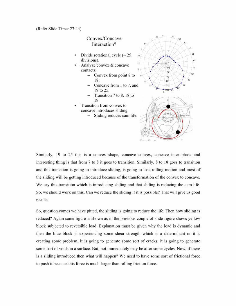
So, we are introducing some additional force here in tangential direction and that tangential
force is going to increase some τmax value. It says that is not increasing the magnitude but, is
in shifting also we can see maximum value here.
The maximum value has increased and is going close to the surface. If it is going closer to the
surface then, removing piece of blue block is easier. So, it is doing both the things first it is
giving high stress and it gives a very close high stress to the surface or near to the surface
which will reduce the life in 2 fold or in 2 ways. If I assume total pitting life is N f number of
cycles or N f when there was no crack non-cracking life that is N 0 crack initiated and after
that there is a propagation crack is moving from sub-surface to surface N p.
Now, let us see if the shear stress magnitude is increasing. We know very well N 0 will come
down deduction in N 0. Further, if this maximum value is shifted towards the crack towards
the surface that means crack is generated very near to the surface. Immediate effect will be
there that means crack also going to reduce N p or we say that when sliding is coming into
picture. It is reducing N 0, it is reducing N p. So, overall life is getting reduced to
demonstrate I will take some section of those blue blocks. We say there is no crack after N 0
cycles, there is some crack generated over here. We can find out and after N f cycles we are
saying after this N f cycles are after N 0. That means when it reaches to N 0 counter again
starts 1 to N f is not.
(Refer Slide Time: 30:50)
HowSlidingreduceslife? Pitting, a fatigue wear, initiates on or near the surface of component.
Tangential force not only increases τ
max but also shifts
position of τmax
to the surface.
Pitting occurs if τmax
> Sys
Total pitting life (Nf)= non-
Cracking life (N0)+crack
propagation life (Np)
after N0 cycles after N
f cycles
In this case N counter starts and 1 to Np comes this will be summation it will be Np plus N0.
The counter is not starting from here, it is starting from here it comes here. It is no starting
from Np it is starting from Nf the first cycle itself. If it is Np then
we can say that after N0 cycles again, restart the counter from one. Again this kind of failure
will come if summation comes N0 plus Np. We can say after Nf cycles first pit is going to be
generated then there is a compromise on the surface. Rough surface comes, there is some sort
of jumper mechanism or jumper phenomenon that is going to create more disturbances in
smooth floor and that is going to generate further more number of impacts, more number of
cracks because of impacting.
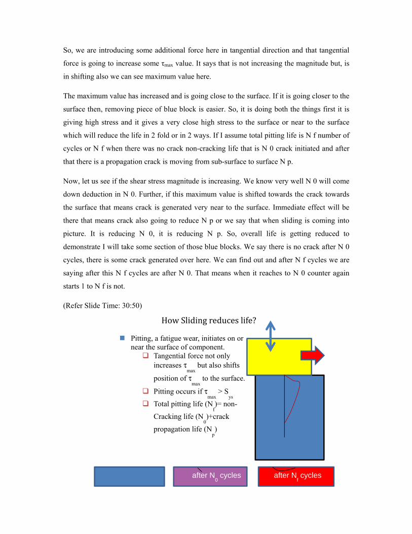
Now, if I go ahead with Hertzian theory or contact stress theory whatever we can get. Instead
of 25, I have used few divisions so that it can be accommodated in one slide and we have
figured out cam contact radius. However, follower cam contact radius is always constant.
Follower radius is not changing. We assume that wear happens on the follower surface which
is negligible compared to the follower radius and the normal load which is coming surface
has been estimated based on force geometry. We can find out what is the maximum
compressive stress, maximum compressive stresses which are estimated using Hertzian
theory. We find that stresses are increasing, first decreasing, then increasing. It reaches to
maximum value over here 4 53 mega Pascal and again it reduces, it reaches roughly to 473
mega Pascal.

(Refer Slide Time: 35:07)
So, we know very well the load is higher similarly, the stress is higher it is coming roughly to
473 mega Pascal again. After that it reduces and reaches to the minimum value which we
have estimated at 0 degree. Same 0 and 360 degree, we know they vary much. This is one of
the validation points. We say that 0 and the 360 should give the same result. We should
whatever we may get the results it should complete one cycle. Now, as I mentioned earlier,
the compressive stress will not initiate fatigue process but, the shear stresses which are
associated with compressive stresses causes the crack formation and once the crack is and
subjected to repeated loading, crack opening and closing will be continuous and finally, the
fracture will occur or pit formation will occur and if the sliding is introduced pit formation
will be much earlier. So, what I am going to conclude from this slide is Hertzian theory is not
sufficient to give explanation for the pitting wear. First thing we need to find out what are the
associated shear stresses which are generated at the sub surface or within the surface? In
Cam angle
Cam contact radius, mm
Normal load on cam surface, N
Maximum normal stress, MPa
0 118.6 1195 -283
45 106.7 862 -242
60 86.2 1653 -342
75 64.4 2174 -404
90 45.7 2489 -453
105 36.5 1794 -399
120 74.4 1344 -237
240 74 1258 -229
255 74.5 1428 -244
270 38.1 2553 -473
285 55.2 2716 -461
300 79.4 1510 -329
315 99.1 1166 -283
330 113 866 -241
345 118.2 1008 -260
360 118.6 1196 -283
FindingContactstress(Hertziantheory)
Compressive stress does not initiate fatigue failure.
Shear stress associated with compressive stresses causes crack formation.
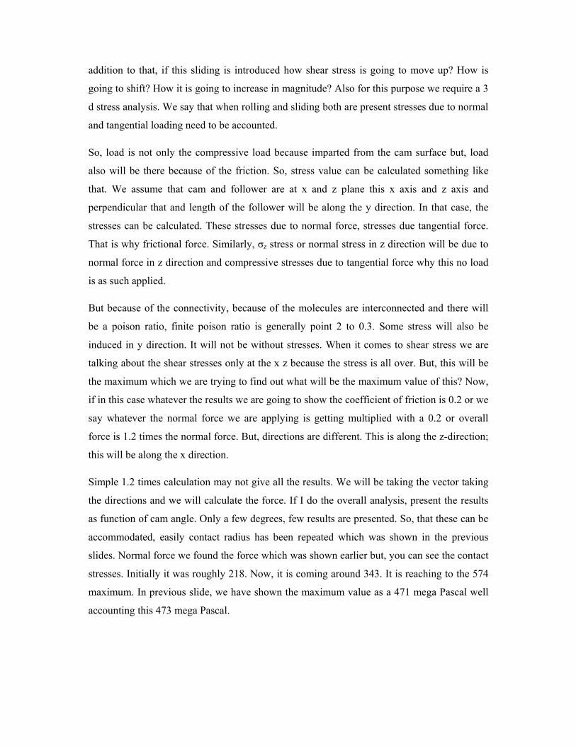
addition to that, if this sliding is introduced how shear stress is going to move up? How is
going to shift? How it is going to increase in magnitude? Also for this purpose we require a 3
d stress analysis. We say that when rolling and sliding both are present stresses due to normal
and tangential loading need to be accounted.
So, load is not only the compressive load because imparted from the cam surface but, load
also will be there because of the friction. So, stress value can be calculated something like
that. We assume that cam and follower are at x and z plane this x axis and z axis and
perpendicular that and length of the follower will be along the y direction. In that case, the
stresses can be calculated. These stresses due to normal force, stresses due tangential force.
That is why frictional force. Similarly, σz stress or normal stress in z direction will be due to
normal force in z direction and compressive stresses due to tangential force why this no load
is as such applied.
But because of the connectivity, because of the molecules are interconnected and there will
be a poison ratio, finite poison ratio is generally point 2 to 0.3. Some stress will also be
induced in y direction. It will not be without stresses. When it comes to shear stress we are
talking about the shear stresses only at the x z because the stress is all over. But, this will be
the maximum which we are trying to find out what will be the maximum value of this? Now,
if in this case whatever the results we are going to show the coefficient of friction is 0.2 or we
say whatever the normal force we are applying is getting multiplied with a 0.2 or overall
force is 1.2 times the normal force. But, directions are different. This is along the z-direction;
this will be along the x direction.
Simple 1.2 times calculation may not give all the results. We will be taking the vector taking
the directions and we will calculate the force. If I do the overall analysis, present the results
as function of cam angle. Only a few degrees, few results are presented. So, that these can be
accommodated, easily contact radius has been repeated which was shown in the previous
slides. Normal force we found the force which was shown earlier but, you can see the contact
stresses. Initially it was roughly 218. Now, it is coming around 343. It is reaching to the 574
maximum. In previous slide, we have shown the maximum value as a 471 mega Pascal well
accounting this 473 mega Pascal.
(Refer Slide Time: 37:57)
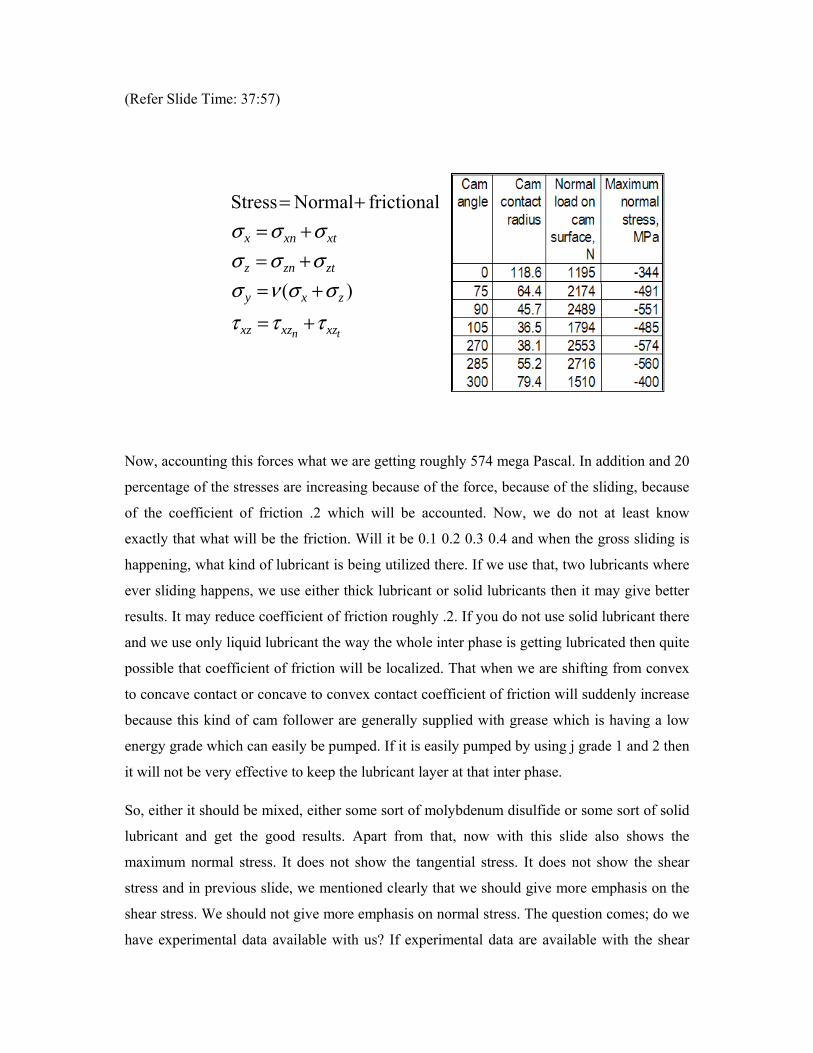
Now, accounting this forces what we are getting roughly 574 mega Pascal. In addition and 20
percentage of the stresses are increasing because of the force, because of the sliding, because
of the coefficient of friction .2 which will be accounted. Now, we do not at least know
exactly that what will be the friction. Will it be 0.1 0.2 0.3 0.4 and when the gross sliding is
happening, what kind of lubricant is being utilized there. If we use that, two lubricants where
ever sliding happens, we use either thick lubricant or solid lubricants then it may give better
results. It may reduce coefficient of friction roughly .2. If you do not use solid lubricant there
and we use only liquid lubricant the way the whole inter phase is getting lubricated then quite
possible that coefficient of friction will be localized. That when we are shifting from convex
to concave contact or concave to convex contact coefficient of friction will suddenly increase
because this kind of cam follower are generally supplied with grease which is having a low
energy grade which can easily be pumped. If it is easily pumped by using j grade 1 and 2 then
it will not be very effective to keep the lubricant layer at that inter phase.
So, either it should be mixed, either some sort of molybdenum disulfide or some sort of solid
lubricant and get the good results. Apart from that, now with this slide also shows the
maximum normal stress. It does not show the tangential stress. It does not show the shear
stress and in previous slide, we mentioned clearly that we should give more emphasis on the
shear stress. We should not give more emphasis on normal stress. The question comes; do we
have experimental data available with us? If experimental data are available with the shear
tn xzxzxz
zxy
ztznz
xtxnx
τττσσνσ
σσσσσσ
+=
+=+=+=
+=
)(
frictionalNormal Stress
stresses then we can find out and we can compare the shear stresses and find out the shear
stress and we compare it with the material stress. Fundamental rule says that if yield strength
is some 500 mega Pascal shear strength will be around 250 mega Pascal 50 percentage of
that.
But, it appears from this kind of surface fatigue phenomena. That stress is not very useful
many times it gives wrong results. So, people have done extensive studies only on normalized
normal forces introducing along with some sort of sliding which gives better results and this
phenomena is common in cam-follower, cam follower mechanism and roller bearings and so
that is why the results are available with us. Just only the normal force and normal force with
the sliding or we say that normal force with pure rolling and normal force with the sliding.
We can utilize those data using the comparative equation results again it may not give 100
percent results but, it gives comparative results to us. So, what I was talking some material
data available. These are cam materials. Mostly, they use grey cast iron or they use nodular
cast iron with different hardness domain. Here we are showing this table as 4 column k is the
constant, sc is the surface compressive strength particularly is number of cycles. As I
mentioned is 10 is to 8 cycles, so this strength for 10 is to 8 cycles it is more like endurance
strength of metals particularly in rolling in fatigue phenomena. In this case is the same thing
but, endurance instead of talking of endurance, we shall talk about the only surface
compressive strength.
Because, it will continuously vary, it will continuously decrease in the number of cycles. If I
increase the number of cycles 10 is to 9, I am sure that this 14000 will reduce around 1400 or
lesser than that. Similarly, there are 2 other constants lambda and zeta. However these 3
parameters are connected something like zeta minus 10 log 10 and is the number of cycles
particularly it can be given in 10 is to 8 cycles 10 is to 6 cycles and there is a lambda.
So, there is a relation a comfort relation given to us. In other way, if we want to increase the
life, if we are able to find out what is the value of k which is required? If I say I want cam
life, cam life to be 10 is to 10 cycles. Now, after that we need to choose proper k proper zeta
proper lambda. So, iterative scheme can be used to find out which result which material will
give me appropriate results. Another is of course, is the table shows when we are introducing
9 percent sliding with rolling or we say 9 percentage energy is getting wasted in sliding. It is
not imparting the rolling motion.
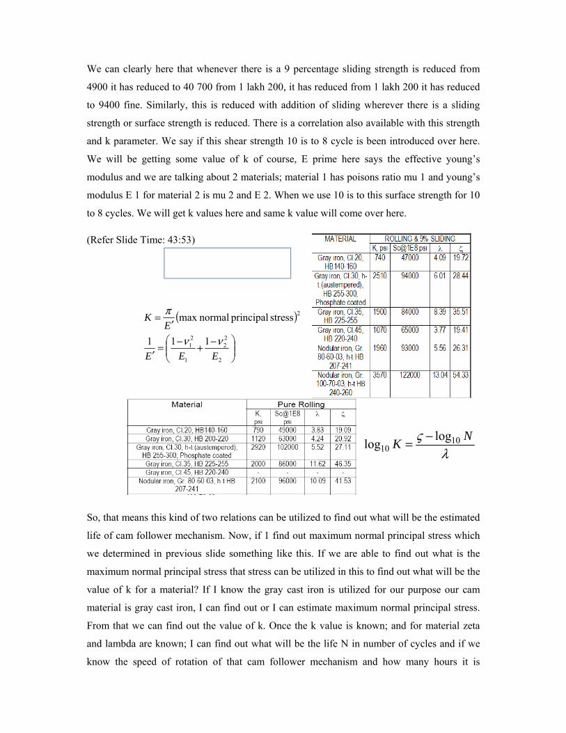
We can clearly here that whenever there is a 9 percentage sliding strength is reduced from
4900 it has reduced to 40 700 from 1 lakh 200, it has reduced from 1 lakh 200 it has reduced
to 9400 fine. Similarly, this is reduced with addition of sliding wherever there is a sliding
strength or surface strength is reduced. There is a correlation also available with this strength
and k parameter. We say if this shear strength 10 is to 8 cycle is been introduced over here.
We will be getting some value of k of course, E prime here says the effective young’s
modulus and we are talking about 2 materials; material 1 has poisons ratio mu 1 and young’s
modulus E 1 for material 2 is mu 2 and E 2. When we use 10 is to this surface strength for 10
to 8 cycles. We will get k values here and same k value will come over here.
(Refer Slide Time: 43:53)
So, that means this kind of two relations can be utilized to find out what will be the estimated
life of cam follower mechanism. Now, if 1 find out maximum normal principal stress which
we determined in previous slide something like this. If we are able to find out what is the
maximum normal principal stress that stress can be utilized in this to find out what will be the
value of k for a material? If I know the gray cast iron is utilized for our purpose our cam
material is gray cast iron, I can find out or I can estimate maximum normal principal stress.
From that we can find out the value of k. Once the k value is known; and for material zeta
and lambda are known; I can find out what will be the life N in number of cycles and if we
know the speed of rotation of that cam follower mechanism and how many hours it is
( )
⎟⎟⎠
⎞⎜⎜⎝
⎛ −+−=′
′=
2
22
1
21
2
111
stress principal normalmax
EEE
EK
νν
π
λς NK 10
10loglog −=
operating in a day. We can find out what will be life in number of days again. This will be
only relative, it will not be absolute if you want to find out of the two, which material it is
going to give you better results and how much better whether 50 percentage better results or
100 percent or more than that that we can choose proper material based on that.
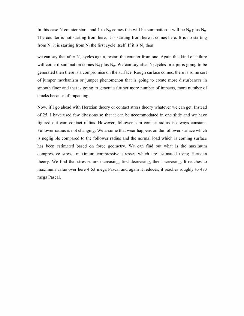
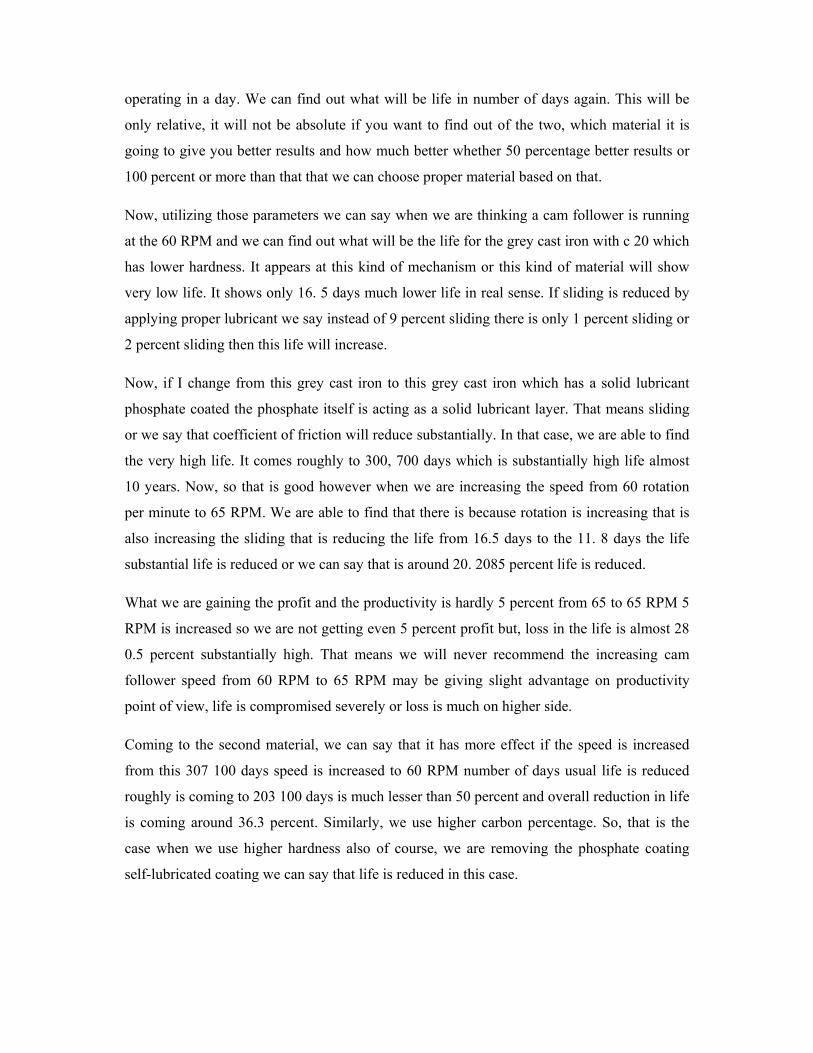
Now, utilizing those parameters we can say when we are thinking a cam follower is running
at the 60 RPM and we can find out what will be the life for the grey cast iron with c 20 which
has lower hardness. It appears at this kind of mechanism or this kind of material will show
very low life. It shows only 16. 5 days much lower life in real sense. If sliding is reduced by
applying proper lubricant we say instead of 9 percent sliding there is only 1 percent sliding or
2 percent sliding then this life will increase.
Now, if I change from this grey cast iron to this grey cast iron which has a solid lubricant
phosphate coated the phosphate itself is acting as a solid lubricant layer. That means sliding
or we say that coefficient of friction will reduce substantially. In that case, we are able to find
the very high life. It comes roughly to 300, 700 days which is substantially high life almost
10 years. Now, so that is good however when we are increasing the speed from 60 rotation
per minute to 65 RPM. We are able to find that there is because rotation is increasing that is
also increasing the sliding that is reducing the life from 16.5 days to the 11. 8 days the life
substantial life is reduced or we can say that is around 20. 2085 percent life is reduced.
What we are gaining the profit and the productivity is hardly 5 percent from 65 to 65 RPM 5
RPM is increased so we are not getting even 5 percent profit but, loss in the life is almost 28
0.5 percent substantially high. That means we will never recommend the increasing cam
follower speed from 60 RPM to 65 RPM may be giving slight advantage on productivity
point of view, life is compromised severely or loss is much on higher side.
Coming to the second material, we can say that it has more effect if the speed is increased
from this 307 100 days speed is increased to 60 RPM number of days usual life is reduced
roughly is coming to 203 100 days is much lesser than 50 percent and overall reduction in life
is coming around 36.3 percent. Similarly, we use higher carbon percentage. So, that is the
case when we use higher hardness also of course, we are removing the phosphate coating
self-lubricated coating we can say that life is reduced in this case.
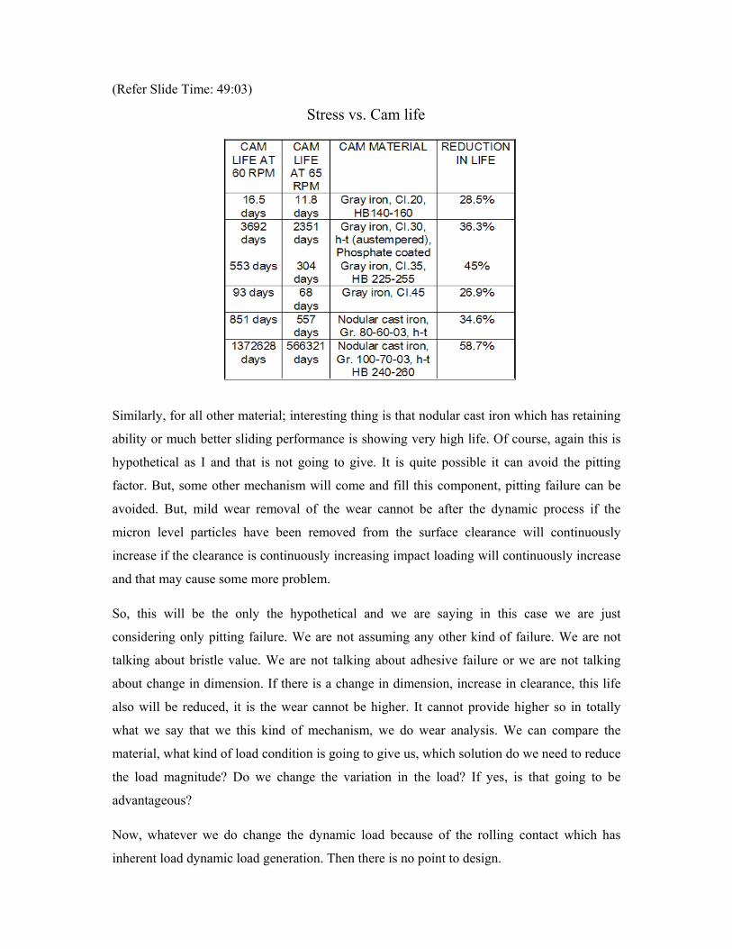
(Refer Slide Time: 49:03)
Similarly, for all other material; interesting thing is that nodular cast iron which has retaining
ability or much better sliding performance is showing very high life. Of course, again this is
hypothetical as I and that is not going to give. It is quite possible it can avoid the pitting
factor. But, some other mechanism will come and fill this component, pitting failure can be
avoided. But, mild wear removal of the wear cannot be after the dynamic process if the
micron level particles have been removed from the surface clearance will continuously
increase if the clearance is continuously increasing impact loading will continuously increase
and that may cause some more problem.
So, this will be the only the hypothetical and we are saying in this case we are just
considering only pitting failure. We are not assuming any other kind of failure. We are not
talking about bristle value. We are not talking about adhesive failure or we are not talking
about change in dimension. If there is a change in dimension, increase in clearance, this life
also will be reduced, it is the wear cannot be higher. It cannot provide higher so in totally
what we say that we this kind of mechanism, we do wear analysis. We can compare the
material, what kind of load condition is going to give us, which solution do we need to reduce
the load magnitude? Do we change the variation in the load? If yes, is that going to be
advantageous?
Now, whatever we do change the dynamic load because of the rolling contact which has
inherent load dynamic load generation. Then there is no point to design.
Stress vs. Cam life
However but, we can say we can provide better lubricant. We can reduce the coefficient of
friction. I have seen industry are applying now with the two lubricants they use high energy, a
grade grease every 10, after every hours they lubricate the surface where the maximum
pitting is occurring and they use additional grease just for the circulation purpose. So, that
can take away the particles and lubricate those surfaces where the severe condition is not
being imposed.
So, those things are there. We will end with this slide on the cam wear analysis and in
addition we are finishing the module 3 which is a wear module. We will be starting next
lecture onward the fourth module. That is the lubrication mechanism and lubricants. What
kinds of lubricants are useful for us or for the machines; which we are planning to design or
we are trying to maintain that mechanism and with this?