
Least Squares Vertex Bakingladislav/kavan11least/kavan11least.pdfVertex baking is common on low-end...
8
Eurographics Symposium on Rendering 2011 Ravi Ramamoorthi and Erik Reinhard (Guest Editors) Volume 30 (2011), Number 4 Least Squares Vertex Baking L. Kavan †1 , A. W. Bargteil 2 and P.-P. Sloan 1 1 Disney Interactive Studios 2 University of Utah (a) (b) (c) (d) Figure 1: Ambient occlusion in the Sibenik cathedral model represented at vertices using (a) point sampling, (b) averaging triangle samples and (c) our method. Compare to (d) ground truth per-pixel rendering. Abstract We investigate the representation of signals defined on triangle meshes using linearly interpolated vertex attributes. Compared to texture mapping, storing data only at vertices yields significantly lower memory overhead and less expensive runtime reconstruction. However, standard approaches to determine vertex values such as point sampling or averaging triangle samples lead to suboptimal approximations. We discuss how an optimal solution can be efficiently calculated using continuous least-squares. In addition, we propose a regularization term that allows us to minimize gradient discontinuities and mach banding artifacts while staying close to the optimum. Our method has been integrated in a game production lighting tool and we present examples of representing signals such as ambient occlusion and precomputed radiance transfer in real game scenes, where vertex baking was used to free up resources for other game components. Categories and Subject Descriptors (according to ACM CCS): I.3.7 [Computer Graphics]: Three-Dimensional Graphics and Realism—Color, shading, shadowing, and texture 1. Introduction Representation of signals on triangle meshes is a classic prob- lem in computer graphics. The standard solution relies on surface parametrization and texture mapping. While this is an efficient representation for high-frequency signals, the asso- ciated memory footprints are often one of the limiting factors in game development. Especially for low-frequency signals it is common to use vertex baking, i.e., representation by linearly interpolated vertex attributes [Gou71]. This is much less expensive, especially for scalar signals such as ambient † [email protected] occlusion [ZIK98, Lan02]—with textures, the uv-coordinates require two scalars per vertex, in addition to the image data. Furthermore, no parametrization or runtime texture memory access is needed. The significantly reduced memory foot- prints and lower shader complexity are important not only in low-end gaming platforms and mobile devices, but also in high-end games that often combine texture mapping and vertex baking [LH09, Wan11]. The question addressed in this paper is how to determine the vertex values to optimally approximate a given signal f defined on a triangle mesh. The most straightforward solution is to point sample f at vertex locations. While under certain c 2011 The Author(s) Computer Graphics Forum c 2011 The Eurographics Association and Blackwell Publish- ing Ltd. Published by Blackwell Publishing, 9600 Garsington Road, Oxford OX4 2DQ, UK and 350 Main Street, Malden, MA 02148, USA.
Transcript of Least Squares Vertex Bakingladislav/kavan11least/kavan11least.pdfVertex baking is common on low-end...

Eurographics Symposium on Rendering 2011Ravi Ramamoorthi and Erik Reinhard(Guest Editors)
Volume 30 (2011), Number 4
Least Squares Vertex Baking
L. Kavan†1, A. W. Bargteil2 and P.-P. Sloan1
1Disney Interactive Studios2University of Utah
(a) (b) (c) (d)
Figure 1: Ambient occlusion in the Sibenik cathedral model represented at vertices using (a) point sampling, (b) averagingtriangle samples and (c) our method. Compare to (d) ground truth per-pixel rendering.
AbstractWe investigate the representation of signals defined on triangle meshes using linearly interpolated vertex attributes.Compared to texture mapping, storing data only at vertices yields significantly lower memory overhead and lessexpensive runtime reconstruction. However, standard approaches to determine vertex values such as point samplingor averaging triangle samples lead to suboptimal approximations. We discuss how an optimal solution can beefficiently calculated using continuous least-squares. In addition, we propose a regularization term that allows usto minimize gradient discontinuities and mach banding artifacts while staying close to the optimum. Our methodhas been integrated in a game production lighting tool and we present examples of representing signals such asambient occlusion and precomputed radiance transfer in real game scenes, where vertex baking was used to free upresources for other game components.
Categories and Subject Descriptors (according to ACM CCS): I.3.7 [Computer Graphics]: Three-DimensionalGraphics and Realism—Color, shading, shadowing, and texture
1. Introduction
Representation of signals on triangle meshes is a classic prob-lem in computer graphics. The standard solution relies onsurface parametrization and texture mapping. While this is anefficient representation for high-frequency signals, the asso-ciated memory footprints are often one of the limiting factorsin game development. Especially for low-frequency signalsit is common to use vertex baking, i.e., representation bylinearly interpolated vertex attributes [Gou71]. This is muchless expensive, especially for scalar signals such as ambient
occlusion [ZIK98, Lan02]—with textures, the uv-coordinatesrequire two scalars per vertex, in addition to the image data.Furthermore, no parametrization or runtime texture memoryaccess is needed. The significantly reduced memory foot-prints and lower shader complexity are important not onlyin low-end gaming platforms and mobile devices, but alsoin high-end games that often combine texture mapping andvertex baking [LH09, Wan11].
The question addressed in this paper is how to determinethe vertex values to optimally approximate a given signal fdefined on a triangle mesh. The most straightforward solutionis to point sample f at vertex locations. While under certain
c© 2011 The Author(s)Computer Graphics Forum c© 2011 The Eurographics Association and Blackwell Publish-ing Ltd. Published by Blackwell Publishing, 9600 Garsington Road, Oxford OX4 2DQ,UK and 350 Main Street, Malden, MA 02148, USA.

L. Kavan & A. Bargteil & P.-P. Sloan / Least Squares Vertex Baking
(a) (b) (c) (d)
Figure 2: Interpolated vertex samples with values determined by (a) point sampling, (b) averaging triangle samples and (c) ourmethod. Compare with (d) ground truth per-pixel rendering.
conditions this is sufficient for exact reconstruction [GW02],in practice we almost always must accept some inaccura-cies. Error is introduced because the vertex density is oftenirregular, the input signal might not be band limited, andthe graphics hardware supports only linear reconstruction.Unfortunately, point sampling does not minimize the approx-imation error and aliasing may occur, see Figure 2a. A moreaccurate approach is to densely sample f inside triangles andcalculate the vertex values by taking barycentric-weighted av-erages [KL06]. This is analogous to low-pass filtering whichreduces aliasing, but at the cost of blurring the result, seeFigure 2b.
One possibility to improve reconstruction accuracy is torefine and/or optimize the mesh. However, game levels oftenpush the limits of the geometry budgets and the artists are notenthusiastic to compromise on scene size or geometric detail.Moreover, geometry refinement would involve unnecessaryreplication of all other vertex attributes (vertices, tangentframes, texture coordinates, etc.) and would impact the wholegame development pipeline, because geometry also servespurposes other than rendering, such as gameplay and physics.
In this paper, we assume a fixed mesh and we formulateand solve an optimization problem that minimizes the errorin a least squares sense, see Figure 2c. However, with morecomplex geometry, the least squares solution is not alwaysas visually pleasing because high variations in vertex valuescan be introduced, see Figure 3a. To remedy this, we studyregularization techniques that trade off accuracy for smooth-ness, allowing us to minimize the mach band artifacts. Ourexperiments indicate that a small amount of regularizationimproves the visual quality considerably while still stayingclose to the optimum.
Our techniques have been implemented in a game pro-duction lighting tool and we provide examples of vertexbaked ambient occlusion and precomputed radiance transferin real game scenes, demonstrating that our method providessmoother and more accurate approximations than previousmethods. From a practical standpoint, vertex baking resultedin significant memory savings compared to textures, freeing
up resources for other components of the game while requir-ing only minimal changes in the development workflows andthe game runtime.
2. Related Work
Vertex baking is common on low-end gaming platforms likethe Nintendo Wii, cell phones and tablets, where memory andpower consumption considerations require that compromisesbe made. On high-end platforms, texture memory consump-tion and shader complexity are still issues and the savingsresulting from vertex baking can significantly improve thequality of the final products [LH09, Wan11]. Another prob-lem is that texture mapping requires parametrization, oftencarefully authored to avoid undesirable uv-seams. In recentyears, texturing techniques that do not require an explicitparametrization have been proposed [BL08, YKH10], but ef-ficient implementations to date have only been presented onhigh-end graphics hardware.
The problem of representing signals on triangle meshesoccurs in many areas of computer graphics. Much of theearly work in Radiosity [CW93] deals with representinglighting signals by point sampling. More accurate resultscan be achieved by adapting the mesh to conform to the sig-nal [HSA91] or by using Galerkin methods [Zat93]. Discon-tinuity meshing [LTG92] refines the mesh at shadow bound-aries to more accurately represent the signal before or duringthe solution. While these methods are important, they are lessuseful in games, where geometry refinement or higher-orderreconstruction functions are typically not an option due toresource limitations and hardware capabilities.
A related approach studied in the literature is to samplea fine mesh and then simplify it to better represent a givensignal [SWH∗95, Hop96]. However, the final signal used inthese techniques is computed using a greedy optimizationprocess which does not come with any optimality guarantees.In this paper, we leverage advances in linear system solversover the past decades [BBK05] to efficiently compute optimalsolutions for a fixed mesh, resulting in higher quality.
c© 2011 The Author(s)c© 2011 The Eurographics Association and Blackwell Publishing Ltd.

L. Kavan & A. Bargteil & P.-P. Sloan / Least Squares Vertex Baking
Precomputed radiance transfer [SKS02] is another tech-nique that usually stores data at the vertices of a mesh. Inthe literature, these meshes are typically finely tessellatedand some work has been done toward computing the solu-tion more efficiently [HR10] or adapting the mesh [KP04].Precomputed radiance transfer, especially if only used forindirect lighting, is another example of a signal that can beefficiently represented using our technique.
Probably the closest work to ours [KL06] reduces aliasingartifacts when storing volumetric irradiance by performingthe volumetric equivalent of the barycentric-weighted aver-ages described in this paper. Note that in spite of the aliasingissues, point sampling at vertex locations is still one of themost common solutions, and in fact is the default in many ap-plications, including Autodesk Maya. The artifacts are eitherresolved during manual post-processing or are masked byanother layer of high-frequency textures. Our method resultsin more visually pleasing approximations, eliminating theneed for any post-processing or masking.
3. Vertex Baking
As input, we have a triangular mesh with vertices v1, . . . ,vNrepresenting a piecewise linear surface S ⊂ R3. We assumethe vertices at creases have been duplicated, i.e., each con-nected component of the mesh corresponds to a smooth patch(smoothing group). We further assume there is an integrablefunction f : S → R that assigns each surface point a scalarvalue (vector functions are handled per-component). The taskis to find vertex values x = (x1, . . . ,xN)
T ∈ RN×1 such thattheir piecewise linear interpolant gx : S → R is as close aspossible to f in the least squares sense, i.e., minimizes
E(x) =∫S( f (p)−gx(p))2 dp (1)
where p is an arbitrary surface point. The function gx can beformally expressed as
gx(p) =N
∑i=1
hi(p)xi (2)
where hi : S → R are piecewise linear hat functions (nodalshape functions from linear finite elements) such that hi(vi) =1 and hi(v j) = 0 for i 6= j. In the following we drop thesubscript from gx for improved readability.
3.1. Optimal Fit
Equation (1) represents a continuous linear least squares prob-lem. To solve it, we substitute Equation (2) into Equation (1)and re-arrange the terms, obtaining
E(x) = xT Ax−2xT b+ c (3)
where A∈RN×N , b∈RN×1 and c∈R are defined as follows
Ai, j =∫S
hi(p)h j(p)dp (4)
bi =∫S
hi(p) f (p)dp (5)
c =∫S
f 2(p)dp (6)
The matrix A is sparse, symmetric positive definite and isalso known as the mass or Gram matrix. Its entries can becalculated analytically: Ai,i is the total area of the trianglesincident to vertex i divided by 6 and Ai, j is the total area of thetriangles incident to edge i j divided by 12 (zeros elsewhere).The vector b and scalar c typically cannot be calculated an-alytically, because we usually do not have a closed-formexpression for f and, therefore, we apply Monte Carlo inte-gration, see Section 3.3.
Because A is positive definite, E(x) is convex and wecan find its global minimum by solving ∂E(x)/∂xi = 0 fori = 1, . . . ,N, which reduces to
Ax = b (7)
A common approximation is to replace A with a diagonalmatrix D such that Di,i =∑
Nj=1 Ai, j =
∫S hi(p)dp, a technique
known as mass-lumping. Note that the mass lumped solutionx̃ = D−1b has components
x̃i =
∫S hi(p) f (p)dp∫S hi(p)dp
(8)
which correspond to a weighted average (with hi being theweighting function [KL06]). However, better results can beachieved by solving Equation (7) exactly, see Figure 2b,c. Wediscuss the numerical solution methods in Section 3.3.
3.2. Regularization
While the least squares formulation from Equation (1) worksvery well for simple scenes as in Figure 2, in more complexscenes the objective E(x) becomes overly eager to exploit allavailable degrees of freedom. For example, Figure 3a showsthe exact solution of Equation (7) applied to a game scene.The piece-wise linear approximation g exhibits large gradientdiscontinuities, visually exacerbated by the mach band effect.
To obtain a better behaved g, we augment the linear systemfrom Equation (7) with a smoothness (or regularization) termR ∈ RN×N , resulting in
(A+αR)x = b (9)
where α≥ 0 is a user-tunable parameter. The simplest choice,inspired by Tikhonov regularization, i.e., R := A, is inade-quate because it corresponds to reducing brightness by push-ing x to zero. A more suitable R should not affect the abso-lute values of x. This motivates gradient-based regularization,
c© 2011 The Author(s)c© 2011 The Eurographics Association and Blackwell Publishing Ltd.

L. Kavan & A. Bargteil & P.-P. Sloan / Least Squares Vertex Baking
Figure 3: Left to right: (a) least squares fit with no regularization, (b) gradient-based regularization (α = 0.1), (c) edge-basedregularization (α = 0.1) and (d) ground truth.
which can be expressed as∫S( f (p)−g(p))2 dp︸ ︷︷ ︸
data term
+α
∫S‖∇g(p)‖2dp︸ ︷︷ ︸
smoothness term
(10)
To obtain the regularization matrix, we note that∇g is piece-wise constant which allows us to split the smoothness termper triangle. For triangle t with vertices vi,v j,vk,
∇g|t = (x j− xi)(vi−vk)
⊥
2at+(xk− xi)
(v j−vi)⊥
2at(11)
where at ∈ R is the area of triangle t and ⊥ denotes acounterclockwise rotation by 90◦ in the plane of the trian-gle [BKP∗10]. One subtle issue is that the units of ∇g|t donot match the units of f (p)− g(p) (the former is inverselyproportional to the units of distance, while the latter is in-dependent of them). This can be fixed by scaling the gradi-ent by the square root of the triangle area, i.e., introducing∇̃g|t :=
√at∇g|t . Employing ∇̃g|t instead of ∇g|t makes
the units of the data and smoothness terms match and cor-responds to giving more weight to the gradients of largertriangles. Because the gradient is linear in x, we can write∇̃g|t = Ftx where Ft is a R3×N sparse matrix. This allowsus to express the regularization term as∫
S‖∇̃g(p)‖2dp = ∑
tat‖∇̃g|t‖
2 = ∑t
atxT FTt Ftx
= xT Rgradx (12)
where Rgrad ∈RN×N is symmetric positive definite. It can beshown Rgrad is closely related to the standard discretizationof the Laplace-Beltrami operator, i.e., the familiar cotangentformula [LZ10].
Employing the regularization term Rgrad leads to asmoother g, see Figure 3b. While Rgrad preserves bright-ness, the side effect is a loss of contrast, because as α→∞,the function g converges to the average of all samples oneach connected component of the mesh. This is obviouslysuboptimal—for example, there is no reason to reduce the gra-dient of an isolated triangle. Therefore, we propose a better
regularization term that explicitly penalizes large gradient dis-continuities across internal mesh edges. Specifically, for eachpair of triangles t and u that share an internal (i.e., non-creaseand non-boundary) edge, we sum
∑(t,u)
(at +au)‖∇̃g|t −∇̃g|u‖2 =
∑(t,u)
(at +au)xT (Ft −Fu)T (Ft −Fu)x = xT Redgex (13)
where Redge ∈ RN×N is a symmetric positive definite edge-based regularization term. Employing this new regularizationterm instead of Rgrad results in solutions that better preservecontrast; for example, notice the effect on the backgroundwall in Figure 3. This is because the matrix Redge encouragessmoother gradients over connected parts of the mesh withoutpenalizing gradient magnitudes at boundaries and creases.
3.3. Numerical Solution
So far we have described how to calculate the system ma-trix. It remains to evaluate the signal-dependent right handside b from Equation (5). Because an explicit formula forf is typically unavailable, we use Monte Carlo integration.Specifically, given approximately uniformly distributed sam-ples p1, . . . ,pM ∈ S, we estimate bi as
bi ≈µi
|Xi| ∑j∈Xi
hi(p j) f (p j) (14)
where Xi is the set of samples in the triangles incident to ver-tex i and µi is the sum of the areas of the triangles incident toi. For ambient occlusion, f (p j) is calculated by importancesampling the hemisphere of rays starting at p j and ray castingagainst the scene geometry using 256 directions. For precom-puted radiance transfer, this process is modified to accountfor spherical harmonics basis functions and 1-bounce indirectlighting [SKS02]. Monte-Carlo integration can also be usedto estimate the coefficient c from Equation (6), but this isonly necessary if the actual numerical value of the error termE(x) is needed.
The system matrix A+αR for α≥ 0 is sparse, symmetric
c© 2011 The Author(s)c© 2011 The Eurographics Association and Blackwell Publishing Ltd.
L. Kavan & A. Bargteil & P.-P. Sloan / Least Squares Vertex Baking
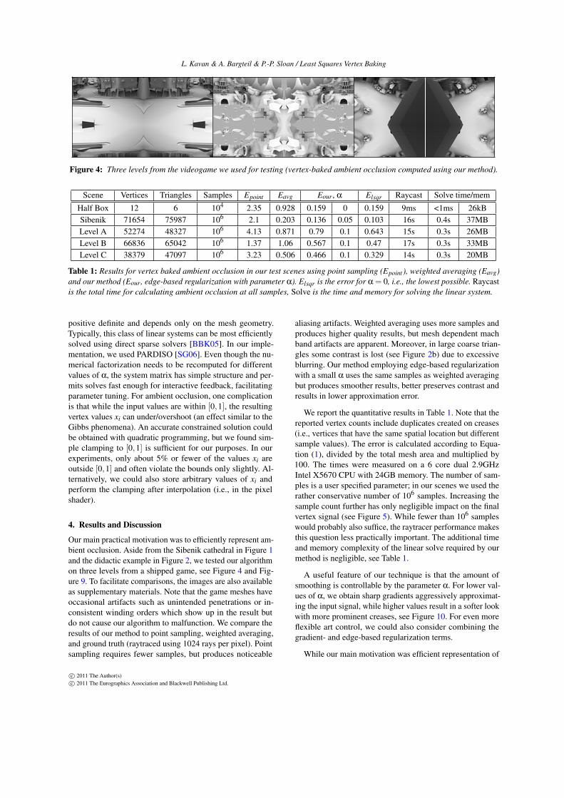
Figure 4: Three levels from the videogame we used for testing (vertex-baked ambient occlusion computed using our method).
Scene Vertices Triangles Samples Epoint Eavg Eour, α Elsqr Raycast Solve time/mem
Half Box 12 6 104 2.35 0.928 0.159 0 0.159 9ms <1ms 26kBSibenik 71654 75987 106 2.1 0.203 0.136 0.05 0.103 16s 0.4s 37MBLevel A 52274 48327 106 4.13 0.871 0.79 0.1 0.643 15s 0.3s 26MBLevel B 66836 65042 106 1.37 1.06 0.567 0.1 0.47 17s 0.3s 33MBLevel C 38379 47097 106 3.23 0.506 0.466 0.1 0.329 14s 0.3s 20MB
Table 1: Results for vertex baked ambient occlusion in our test scenes using point sampling (Epoint ), weighted averaging (Eavg)and our method (Eour, edge-based regularization with parameter α). Elsqr is the error for α = 0, i.e., the lowest possible. Raycastis the total time for calculating ambient occlusion at all samples, Solve is the time and memory for solving the linear system.
positive definite and depends only on the mesh geometry.Typically, this class of linear systems can be most efficientlysolved using direct sparse solvers [BBK05]. In our imple-mentation, we used PARDISO [SG06]. Even though the nu-merical factorization needs to be recomputed for differentvalues of α, the system matrix has simple structure and per-mits solves fast enough for interactive feedback, facilitatingparameter tuning. For ambient occlusion, one complicationis that while the input values are within [0,1], the resultingvertex values xi can under/overshoot (an effect similar to theGibbs phenomena). An accurate constrained solution couldbe obtained with quadratic programming, but we found sim-ple clamping to [0,1] is sufficient for our purposes. In ourexperiments, only about 5% or fewer of the values xi areoutside [0,1] and often violate the bounds only slightly. Al-ternatively, we could also store arbitrary values of xi andperform the clamping after interpolation (i.e., in the pixelshader).
4. Results and Discussion
Our main practical motivation was to efficiently represent am-bient occlusion. Aside from the Sibenik cathedral in Figure 1and the didactic example in Figure 2, we tested our algorithmon three levels from a shipped game, see Figure 4 and Fig-ure 9. To facilitate comparisons, the images are also availableas supplementary materials. Note that the game meshes haveoccasional artifacts such as unintended penetrations or in-consistent winding orders which show up in the result butdo not cause our algorithm to malfunction. We compare theresults of our method to point sampling, weighted averaging,and ground truth (raytraced using 1024 rays per pixel). Pointsampling requires fewer samples, but produces noticeable
aliasing artifacts. Weighted averaging uses more samples andproduces higher quality results, but mesh dependent machband artifacts are apparent. Moreover, in large coarse trian-gles some contrast is lost (see Figure 2b) due to excessiveblurring. Our method employing edge-based regularizationwith a small α uses the same samples as weighted averagingbut produces smoother results, better preserves contrast andresults in lower approximation error.
We report the quantitative results in Table 1. Note that thereported vertex counts include duplicates created on creases(i.e., vertices that have the same spatial location but differentsample values). The error is calculated according to Equa-tion (1), divided by the total mesh area and multiplied by100. The times were measured on a 6 core dual 2.9GHzIntel X5670 CPU with 24GB memory. The number of sam-ples is a user specified parameter; in our scenes we used therather conservative number of 106 samples. Increasing thesample count further has only negligible impact on the finalvertex signal (see Figure 5). While fewer than 106 sampleswould probably also suffice, the raytracer performance makesthis question less practically important. The additional timeand memory complexity of the linear solve required by ourmethod is negligible, see Table 1.
A useful feature of our technique is that the amount ofsmoothing is controllable by the parameter α. For lower val-ues of α, we obtain sharp gradients aggressively approximat-ing the input signal, while higher values result in a softer lookwith more prominent creases, see Figure 10. For even moreflexible art control, we could also consider combining thegradient- and edge-based regularization terms.
While our main motivation was efficient representation of
c© 2011 The Author(s)c© 2011 The Eurographics Association and Blackwell Publishing Ltd.
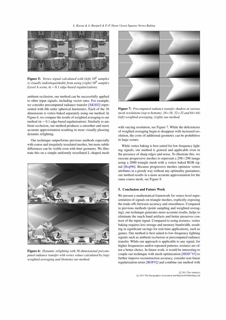
L. Kavan & A. Bargteil & P.-P. Sloan / Least Squares Vertex Baking
Figure 5: Vertex signal calculated with (left) 106 samplesis visually indistinguishable from using (right) 108 samples(Level A scene, α = 0.1 edge-based regularization).
ambient occlusion, our method can be successfully appliedto other input signals, including vector ones. For example,we consider precomputed radiance transfer [SKS02] repre-sented with 6th order spherical harmonics. Each of the 36dimensions is vertex-baked separately using our method. InFigure 6, we compare the results of weighted averaging to ourmethod (α = 0.1 edge-based regularization). Similarly to am-bient occlusion, our method produces a smoother and moreaccurate approximation resulting in more visually pleasingdynamic relighting.
Our technique outperforms previous methods especiallywith coarse and irregularly tesselated meshes, but more subtledifferences can be visible even with finer geometry. We illus-trate this on a simple uniformly tessellated L-shaped mesh
Figure 6: Dynamic relighting with 36-dimensional precom-puted radiance transfer with vertex values calculated by (top)weighted averaging and (bottom) our method.
Figure 7: Precomputed radiance transfer shadow at variousmesh resolutions (top to bottom): 16×16, 32×32 and 64×64;(left) weighted averaging, (right) our method.
with varying resolution, see Figure 7. While the deficienciesof weighted averaging begin to disappear with increased res-olution, the costs of additional geometry can be prohibitivein large scenes.
While vertex baking is best suited for low-frequency light-ing signals, our method is general and applicable even inthe presence of sharp edges and noise. To illustrate this, weexecute progressive meshes to represent a 298×298 imageusing a 2000 triangle mesh with a vertex baked RGB sig-nal [Hop96]. Because progressive meshes optimize vertexattributes in a greedy way without any optimality guarantees,our method results in a more accurate approximation for thesame coarse mesh, see Figure 8.
5. Conclusion and Future Work
We present a mathematical framework for vertex-level repre-sentation of signals on triangle meshes, explicitly exposingthe trade-offs between accuracy and smoothness. Comparedto previous methods (point sampling and weighted averag-ing), our technique generates more accurate results, helps toeliminate the mach band artifacts and better preserves con-trast of the input signal. Compared to using textures, vertexbaking requires less storage and memory bandwidth, result-ing in significant savings for real-time applications, such asgames. Our method is best suited to low-frequency lightingsignals such as ambient occlusion or precomputed radiancetransfer. While our approach is applicable to any signal, forhigher frequencies and/or repeated patterns, textures are of-ten a better choice. In future work, it would be interesting tocouple our technique with mesh optimization [HDD∗93] tofurther improve reconstruction accuracy, consider non-linearregularization terms [ROF92] and combine our method with
c© 2011 The Author(s)c© 2011 The Eurographics Association and Blackwell Publishing Ltd.

L. Kavan & A. Bargteil & P.-P. Sloan / Least Squares Vertex Baking
Figure 8: An image represented by a vertex baked RGB signal on a coarse mesh (left to right): (a) the original progressivemeshes result, (b) weighted averaging and (c) our method. Compare to (d) the original image.
emerging texturing schemes [YKH10]. An extension of ourmethod to higher order basis functions [SSD03] could bederived by replacing our piecewise linear hat functions hi(Section 3) with higher order ones. The increased cost ofruntime interpolation would be balanced by higher approxi-mation quality for the same number of degrees of freedom,especially with strictly C1-conforming schemes [CO01].
Acknowledgements. We thank the anonymous reviewersfor their feedback and helpful comments. Many thanks toJeff Grills, Robert Kovach and Tony Bratton for help withintegration in production tools and Peter Shirley for carefulproofreading.
References[BBK05] BOTSCH M., BOMMES D., KOBBELT L.: Efficient
linear system solvers for mesh processing. In Mathematics ofSurfaces XI, Martin R., Bez H., Sabin M., (Eds.), vol. 3604 ofLecture Notes in Computer Science. 2005, pp. 62–83. 2, 5
[BKP∗10] BOTSCH M., KOBBELT L., PAULY M., ALLIEZ P.,LEVY B.: Polygon Mesh Processing. AK Peters, 2010. 4
[BL08] BURLEY B., LACEWELL D.: Ptex: Per-face texture map-ping for production rendering. In Eurographics Symposium onRendering 2008 (2008), pp. 1155–1164. 2
[CO01] CIRAK F., ORTIZ M.: Fully C1-conforming subdivisionelements for finite deformation thin-shell analysis. Journal forNumerical Methods in Engineering 51 (2001), 813–833. 7
[CW93] COHEN M. F., WALLACE J. R.: Radiosity and RealisticImage Synthesis. Academic Press Professional, San Diego, CA,1993. 2
[Gou71] GOURAUD H.: Continuous shading of curved surfaces.IEEE Trans. Comput. 20 (June 1971), 623–629. 1
[GW02] GONZALEZ R. C., WOODS R. E.: Digital Image Pro-cessing. Prentice Hall, 2002. 2
[HDD∗93] HOPPE H., DEROSE T., DUCHAMP T., MCDONALDJ., STUETZLE W.: Mesh optimization. Proceedings of SIG-GRAPH ‘93 (1993), 19–26. 6
[Hop96] HOPPE H.: Progressive meshes. Proceedings of SIG-GRAPH ‘96 (1996), 99–108. 2, 6
[HR10] HUANG F.-C., RAMAMOORTHI R.: Sparsely Precomput-ing the Light Transport Matrix for Real-Time Rendering. Com-puter Graphics Forum (Proc. EGSR’10) 29, 2 (8 2010), 1335–1345. 3
[HSA91] HANRAHAN P., SALZMAN D., AUPPERLE L.: A RapidHierarchical Radiosity Algorithm. In Computer Graphics (Pro-ceedings of SIGGRAPH ’91) (1991), vol. 25, pp. 197–206. 2
[KL06] KONTKANEN J., LAINE S.: Sampling precomputed volu-metric lighting. J. Graphics Tools 11, 3 (2006), 1–16. 2, 3
[KP04] KRIVANEK J., PATTANAIK S.: Adaptive mesh subdivsionfor precomputed radiance transfer. In Proceedings of the TwentiethSpring Conference on Computer Graphics (SCCG 2004) (2004),pp. 106–111. 3
[Lan02] LANDIS H.: Global illumination in production. ACMSIGGRAPH 2002 Course #16 Notes, July 2002. 1
[LH09] LARSSON D., HALEN H.: The unique lighting of Mirror’sEdge. In Game Developers Conference (2009). 1, 2
[LTG92] LISCHINSKI D., TAMPIERI F., GREENBERG D. P.: Dis-continuity meshing for accurate radiosity. IEEE Computer Graph-ics and Applications 12, 6 (Nov. 1992), 25–39. 2
[LZ10] LÉVY B., ZHANG R. H.: Spectral geometry processing.In ACM SIGGRAPH Course Notes (2010). 4
[ROF92] RUDIN L. I., OSHER S., FATEMI E.: Nonlinear totalvariation based noise removal algorithms. Physica D: NonlinearPhenomena 60, 1-4 (1992), 259 – 268. 6
[SG06] SCHENK O., GARTNER K.: On fast factorization pivotingmethods for symmetric indefinite systems. Elec. Trans. Numer.Anal. 23 (2006), 58–179. 5
[SKS02] SLOAN P.-P., KAUTZ J., SNYDER J.: Precomputed radi-ance transfer for real-time rendering in dynamic, low-frequencylighting environments. ACM Trans. Graph. (2002). 3, 4, 6
[SSD03] SOLIN P., SEGETH K., DOLEZEL I.: Higher-OrderFinite Element Methods. Chapman and Hall/CRC, 2003. 7
[SWH∗95] SHIRLEY P., WADE B., HUBBARD P., ZARESKI D.,WALTER B., GREENBERG D. P.: Global illumination via densityestimation. In Eurographics Rendering Workshop 1995 (June1995), Eurographics. 2
[Wan11] WANG X.: Automated level of detail generation forHALO: REACH. In Game Developers Conference (2011). 1, 2
[YKH10] YUKSEL C., KEYSER J., HOUSE D. H.: Mesh colors.ACM Trans. Graph. 29, 2 (2010), 1–11. 2, 7
[Zat93] ZATZ H. R.: Galerkin radiosity: A higher order solutionmethod for global illumination. In SIGGRAPH 93 ConferenceProceedings (1993), pp. 213–220. 2
[ZIK98] ZHUKOV S., INOES A., KRONIN G.: An ambient lightillumination model. In Rendering Techniques ’98 (1998), pp. 45–56. 1
c© 2011 The Author(s)c© 2011 The Eurographics Association and Blackwell Publishing Ltd.
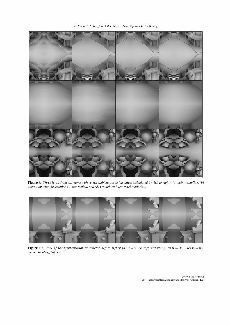
L. Kavan & A. Bargteil & P.-P. Sloan / Least Squares Vertex Baking
Figure 9: Three levels from our game with vertex ambient occlusion values calculated by (left to right): (a) point sampling, (b)averaging triangle samples, (c) our method and (d) ground truth per-pixel rendering.
Figure 10: Varying the regularization parameter (left to right): (a) α = 0 (no regularization), (b) α = 0.01, (c) α = 0.1(recommended), (d) α = 1.
c© 2011 The Author(s)c© 2011 The Eurographics Association and Blackwell Publishing Ltd.


![[STP]"Nintendo Wii"](https://static.fdocuments.net/doc/165x107/55611fe9d8b42aa06b8b47ad/stpnintendo-wii.jpg)