Learning gaze biases with head motion for head pose …arts.buaa.edu.cn/papers/Learning gaze biases...
11
Learning gaze biases with head motion for head pose-free gaze estimation ☆ Feng Lu a, ⁎, Takahiro Okabe b , Yusuke Sugano a , Yoichi Sato a a The University of Tokyo, Japan b Kyushu Institute of Technology, Japan abstract Keywords: Gaze estimation Free head motion Head pose compensation Appearance-based approach When estimating human gaze directions from captured eye appearances, most existing methods assume a fixed head pose because head motion changes eye appearance greatly and makes the estimation inaccurate. To handle this difficult problem, in this paper, we propose a novel method that performs accurate gaze estimation without restricting the user's head motion. The key idea is to decompose the original free-head motion problem into sub- problems, including an initial fixed head pose problem and subsequent compensations to correct the initial esti- mation biases. For the initial estimation, automatic image rectification and joint alignment with gaze estimation are introduced. Then compensations are done by either learning-based regression or geometric-based calcula- tion. The merit of using such a compensation strategy is that the training requirement to allow head motion is not significantly increased; only capturing a 5-s video clip is required. Experiments are conducted, and the results show that our method achieves an average accuracy of around 3° by using only a single camera. 1. Introduction Human gaze plays an essential role in conveying human visual at- tention, desire, feeling, intention, and so on [1]. Therefore, research on human gaze estimation has been an important topic since decades ago [2] and has attracted much attention in recent years. There are already systems in the market that have been used in many applications, such as human–computer interfaces, cognitive study, market research, and driver training. However, these existing systems usually require expen- sive devices, which stop them from being widely used by ordinary users in their everyday lives. With the fast development of computer vision technology, it seems possible that human gaze direction can be estimated by only using captured eye images without requiring too much additional hardware. This will greatly enhance the applicability of gaze estimation technolo- gy. According to recent surveys [3,4], existing computer vision-based methods can be roughly divided into two categories: model-based methods and appearance-based methods. Methods in the first category assume 3D or 2D eyeball models to estimate gaze directions, while they still need some additional devices such as infrared lights and cameras. Therefore, they are more suitable for use in a controlled environment such as in the laboratory. Appearance-based methods have the advantage of using only a single common camera, and thus, they attract increasing attention. In this paper, we focus on the appearance-based methods and solve the major difficulty in allowing free head motion. This problem is difficult because head motion changes eye appearance greatly, and therefore, gaze estimation with changed eye appearances will be inac- curate. A straightforward way to solve this problem is to store all the eye appearances for every individual head pose in the system. However, because head motion has 6 degrees of freedom, it becomes impractical to directly deal with all possible eye appearances due to head motion. The key idea of this paper is to decompose the originally difficult problem into simple subproblems and solve them efficiently. In partic- ular, instead of considering gaze estimation for arbitrary head poses, we first apply gaze estimation by assuming a fixed head pose, and then compensate for the estimation biases caused by the head pose difference. The compensation comprises two stages, namely, eye ap- pearance distortion compensation and geometric compensation. We propose methods to complete these compensations and show that the gaze estimation can be done accurately for arbitrary head poses. The primary contributions of this work are: (1) A gaze estimation approach that decomposes the difficult free head motion problem into much easier subproblems is proposed. (2) Subproblems are solved with our proposed compensation met- hods, which correct gaze estimation biases due to both eye ap- pearance distortion and geometric factors. (3) The training cost for compensating for head motion is low. It only requires capturing a short video clip of user free head motion for a duration of 5 s.
Transcript of Learning gaze biases with head motion for head pose …arts.buaa.edu.cn/papers/Learning gaze biases...
Learning gaze biases with head motion for head pose-freegaze estimation☆
Feng Lu a,⁎, Takahiro Okabe b, Yusuke Sugano a, Yoichi Sato a
a The University of Tokyo, Japanb Kyushu Institute of Technology, Japan
a b s t r a c t
Keywords:Gaze estimationFree head motionHead pose compensationAppearance-based approach
When estimating human gaze directions from captured eye appearances, most existing methods assume a fixedhead pose because headmotion changes eye appearance greatly andmakes the estimation inaccurate. To handlethis difficult problem, in this paper, we propose a novel method that performs accurate gaze estimation withoutrestricting the user's headmotion. The key idea is to decompose the original free-headmotion problem into sub-problems, including an initial fixed head pose problem and subsequent compensations to correct the initial esti-mation biases. For the initial estimation, automatic image rectification and joint alignment with gaze estimationare introduced. Then compensations are done by either learning-based regression or geometric-based calcula-tion. The merit of using such a compensation strategy is that the training requirement to allow head motion isnot significantly increased; only capturing a 5-s video clip is required. Experiments are conducted, and the resultsshow that our method achieves an average accuracy of around 3° by using only a single camera.
1. Introduction
Human gaze plays an essential role in conveying human visual at-tention, desire, feeling, intention, and so on [1]. Therefore, research onhuman gaze estimation has been an important topic since decades ago[2] and has attracted much attention in recent years. There are alreadysystems in the market that have been used in many applications, suchas human–computer interfaces, cognitive study, market research, anddriver training. However, these existing systems usually require expen-sive devices, which stop them from beingwidely used by ordinary usersin their everyday lives.
With the fast development of computer vision technology, it seemspossible that human gaze direction can be estimated by only usingcaptured eye images without requiring too much additional hardware.This will greatly enhance the applicability of gaze estimation technolo-gy. According to recent surveys [3,4], existing computer vision-basedmethods can be roughly divided into two categories: model-basedmethods and appearance-based methods. Methods in the first categoryassume 3D or 2D eyeball models to estimate gaze directions, while theystill need some additional devices such as infrared lights and cameras.Therefore, they are more suitable for use in a controlled environmentsuch as in the laboratory. Appearance-based methods have the
advantage of using only a single common camera, and thus, they attractincreasing attention.
In this paper, we focus on the appearance-based methods and solvethe major difficulty in allowing free head motion. This problem isdifficult because head motion changes eye appearance greatly, andtherefore, gaze estimation with changed eye appearances will be inac-curate. A straightforward way to solve this problem is to store all theeye appearances for every individual head pose in the system. However,because head motion has 6 degrees of freedom, it becomes impracticalto directly deal with all possible eye appearances due to head motion.
The key idea of this paper is to decompose the originally difficultproblem into simple subproblems and solve them efficiently. In partic-ular, instead of considering gaze estimation for arbitrary head poses,we first apply gaze estimation by assuming a fixed head pose, andthen compensate for the estimation biases caused by the head posedifference. The compensation comprises two stages, namely, eye ap-pearance distortion compensation and geometric compensation. Wepropose methods to complete these compensations and show that thegaze estimation can be done accurately for arbitrary head poses.
The primary contributions of this work are:
(1) A gaze estimation approach that decomposes the difficult freeheadmotion problem intomuch easier subproblems is proposed.
(2) Subproblems are solved with our proposed compensation met-hods, which correct gaze estimation biases due to both eye ap-pearance distortion and geometric factors.
(3) The training cost for compensating for headmotion is low. It onlyrequires capturing a short video clip of user free head motion fora duration of 5 s.
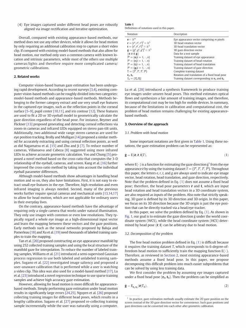
Table 1Definitions of notations used in this paper.
Notation Description
e ∈ ℝm Eye appearance vector comprising m pixelsr = [rx, ry, rz]T ∈ ℝ3 3D head rotation vectort = [tx, ty, tz]T ∈ ℝ3 3D head translation vectorg = [gx, gy, gz]T ∈ ℝ3 3D gaze direction vectore; r; t; g� �
Data for a test sampleTg = {ei|i = 1, ⋯, n} Training dataset of eye appearanceTg = {ri|i = 1, ⋯, n} Training dataset of head rotationTg = {ti|i = 1, ⋯, n} Training dataset of head translationTg = {gi|i = 1, ⋯, n} Training dataset of gaze directionT = {Te, Tr, Tt, Tg} Complete training datasetr0, t0 Rotation and translation of a fixed head poseT0 = {T0e,T0g} Training dataset corresponding to r0 and t0
1 In practice, gaze estimation methods usually estimate the 2D gaze position on thescreen instead of the 3D gaze direction vector for convenience. Such gaze positions andgaze directions can be converted into each other after geometric calibration.
(4) Eye images captured under different head poses are robustlyaligned via image rectification and iterative optimization.
Overall, compared with existing appearance-based methods, ourmethod does not use any other devices, while it allows for head motionby only requiring an additional calibration step to capture a short videoclip. If comparedwith existingmodel-basedmethods that also allow forhead motion, our method only uses a common camera with known lo-cation and intrinsic parameters, while most of the others use multiplecameras/lights and therefore require more complicated camera/geometric calibrations.
2. Related works
Computer vision-based human gaze estimation has been undergo-ing rapid development. According to recent surveys [3,4], existing com-puter vision-basedmethods can be roughly divided into two categories:model-based methods and appearance-based methods. Methods be-longing to the former category extract and use very small eye featuresin the captured eye images, such as the reflection points in the cornealsurface [5–9], pupil center [10,11], and iris contour [12]. These featuresare used to fit a 2D or 3D eyeball model to geometrically calculate thegaze direction regardless of the head pose. For instance, Beymer andFlickner [13] proposed generating and detecting corneal reflections viazoom-in cameras and infrared LEDs equipped on stereo pan-tilt units.Additionally, two additional wide range stereo cameras are used foreye position tracking. Brolly andMulligan [14] proposed a similarmeth-od for accurately extracting and using corneal reflection points, as wellas did Nagamatsu et al. [15] and Zhu and Ji [7]. To reduce number ofcameras, Villanueva and Cabeza [8] suggested using more infraredLEDs to achieve accurate geometric calculation. Yoo and Chung [5] pro-posed a novel method based on the cross-ratio that computes the 3-Drelationship of the eyeball, cameras, and screen. Kang et al. [16] furtherimproved the cross-ratio method by taking into account the individualeyeball parameter differences.
Although model-based methods show advantages in handling headmotion and so on, they also have limitations. First, it is not easy to ex-tract small eye features in the eye. Therefore, high resolution and eveninfrared imaging is always needed. Second, many of the previousworks further require special cameras and mechanical units [13,14,17]to allow for head motion, which are not applicable for ordinary usersin their everyday lives.
On the contrary, appearance-based methods have the advantage ofrequiring only a single camera that works under natural illumination.They only use images with common or even low resolutions. They ty-pically regard a whole eye image as a high-dimensional input vectorand learn the mapping between these vectors and the gaze positions.Early methods such as the neural networks proposed by Baluja andPomerleau [18] andXu et al. [19] need thousands of labeled training sam-ples to train the mapping.
Tan et al. [20] proposed constructing an eye appearancemanifold byusing 252 collected training samples and using the local structure of themanifold gaze for interpolation. To reduce the number of labeled train-ing samples, Williams et al. [21] introduced a semi-supervised Gaussianprocess regression to use both labeled and unlabeled training sam-ples. Sugano et al. [22] investigated image saliency and proposed auser-unaware calibration that is performed while a user is watchinga video clip. This idea was also used for a model-based method [17]. Luet al. [23] introduced a novel regression technique to use sparse trainingsamples and achieve high accuracy gaze estimation.
However, allowing for headmotion is more difficult for appearance-based methods. Simply performing gaze estimation under headmotionresults in significantly large errors [24,25]. Nguyen et al. [26] proposedcollecting training images for different head poses, which results in alengthy calibration. Sugano et al. [27] proposed re-collecting trainingsample incrementally while the user was naturally using a computer.
Lu et al. [28] introduced a synthesis framework to produce trainingeye images under unseen head poses. This method estimates opticalflows and synthesizes a fair amount of training images, and therefore,its computational cost may be too high for mobile devices. In summary,because of the limitations in calibration and computational cost, theproblem of head motion remains challenging for existing appearance-based methods.
3. Overview of the approach
3.1. Problem with head motion
Some important notations are first given in Table 1. Using these no-tations, the gaze estimation problem can be represented as:
g ¼ E e; r; t� ��TÞ; ð1Þ
where E(·) is a function for estimating the gaze directiong1 from the eyeappearance e by using the training dataset T={Te, Tr, Tt, Tg}. Throughoutthis paper, the letters e, r, t, and g are always used to indicate eye imagevector, head rotation, head translation, and gaze direction, respectively.Note that the problem defined in Eq. (1) does not assume a fixed headpose; therefore, the head pose parameters r and t, which are inputhead rotation and head translation vectors in a 3D coordinate system,are also required as inputs of the problem. Also note that strictly speak-ing, 3D gaze is defined by its 3D direction and 3D origin. In this paper,we focus on its 3D direction because the 3D origin is just the eye posi-tion that can be directly tracked via a head/eye tracker.
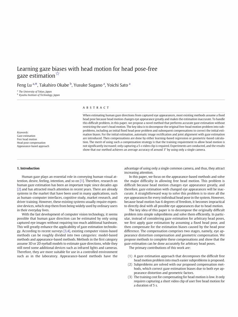
In this paper, we solve the problem defined by Eq. (1). As shown inFig. 1, our goal is to estimate the gaze direction g under the world coor-dinate system (WCS), while the head coordinate system (HCS) deter-mined by head pose r; t
� �can be arbitrary due to head motion.
3.2. Decomposition of the problem
The free head motion problem defined in Eq. (1) is difficult becauseit requires the training dataset T, which corresponds to 6-degree-of-freedom head motion to sufficiently train the mapping function E(·).Therefore, as reviewed in Section 2, most existing appearance-basedmethods assume a fixed head pose. In this paper, we proposedecomposing this difficult problem into much easier subproblems thatcan be solved by using less training data.
We first consider the problem by assuming eye images capturedunder a fixed head pose (r0, t0). Then the problem can be simplified as
g ¼ Er0 ;t0 eð jT0Þ; ð2Þ
Y
X
Z
]
Head coord. sys.
World coord. sys.
Fig. 1.Gaze estimationwith headmotion. Gaze direction g is estimated under world coor-dinate system with arbitrary head rotation r and translation t.
where T0 = {T0e,T0g} is the training dataset collected for the fixed headpose (r0, t0), and function Er0 ;t0 (·) performs gaze estimation only forsuch a fixed head pose. This subproblem can be easily solved by usingprevious methods to give an initial solution.
However, the above gaze estimation may contain significant error ifthe head moves. Fig. 2 gives an example with temporary notations α, β,etc. As shown in Fig. 2(a), the estimated gaze direction under a fixedhead pose, r0, t0, is α. Then, if the head pose moves to r; t
� �as in
Fig. 2(b), the estimated gaze direction α′ will differ from the true gazedirection by a bias, β. Therefore, we need to compensate for α′ byusing β to obtain the correct gaze direction. This leads to the idea ofgaze compensation.
Furthermore, compensation for gaze bias can be further decom-posed into two stages, as shown in Fig. 2(c). First, α′ differs from α be-cause head motion changes the camera's viewing direction and thusdistorts the eye image (see the small eye image in Fig. 2). This causesan estimation bias, βD. Second, the gaze direction rotates with head ro-tation geometrically, and this causes another bias, βG. Note that βG has aprecise closed-form solution that can be geometrically computed, whileβD does not. For this reason, in this paper, we treat the two compensa-tions separately, and therefore, uncertainty mainly goes to βD; thus,the total error is limited. Another reason to do so is that computing βG
only requires head rotation angles as inputs, while βD depends on thecamera's viewing direction that is related to all head pose parameters.Therefore, it is better to treat these two compensation problemsseparately.
By considering the above compensations, the problem in Eq. (1) canbe decomposed into
g≃Er0 ;t0 eð jT0Þ⊗CDr0 ;t0 r; t� ��TÞ⊗CG
r0 rð Þ; ð3Þ
where Er0 ;t0 eð jT0Þ indicates an initial gaze direction by assuming a fixedhead pose, (r0, t0). Operator “⊗” applies manipulations on the gaze di-rection via a series of rotations, and CD
r0 ;t0 r; t� ��TÞ and CG
r0 rð Þ denote the
00r t
α
( , ) β
'α
(a) (b)
Fig. 2. 2D illustration of problem decomposition. (a) Assuming a fixed head pose (r0, t0), gaze ddistorted; thus, Eq. (2) estimates gaze direction (blue dashed line) as α′. It differs from real gazdue to eye image distortion (βD = α − α′) and one due to geometric head motion (βG = head
specific compensations for eye appearance distortion and geometricbias.
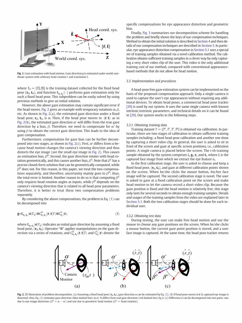
Finally, Fig. 3 summarizes our decomposition scheme for handlingthe problem and briefly shows the keys of our compensation techniques.Method to obtain the initial solution is described in Section 4 and thende-tails of our compensation techniques are described in Section 5. In partic-ular, eye appearance distortion compensation in Section 5.1 uses a specialset of training samples obtained via a novel calibration method. The cali-bration obtains sufficient training samples in a cleverway by only captur-ing a very short video clip of the user. This video is the only additionaltraining cost of our method, compared with conventional appearance-based methods that do not allow for head motion.
3.3. Implementation and procedures
Ahead-pose free gaze estimation systemcan be implemented on thebasis of the proposed compensation approach. Only a single camera isused to capture the user's eye appearances without requiring any addi-tional devices. To obtain head poses, a commercial head pose tracker[29] is used by our system. It uses the same single camera with knownintrinsic/extrinsic parameters, and technical details on it can be foundin [29]. Our system works in the following steps.
3.3.1. Obtaining training dataTraining dataset T= {Te, Tr, Tt, Tg} is obtained via calibration. In par-
ticular, there are two stages of calibration to obtain sufficient trainingsamples including: a fixed head pose calibration and another one doneby capturing a short video clip. In general, the user is asked to sit infront of the screen and gaze at specific screen positions, i.e., calibrationpoints. A single camera is placed below the screen. The i-th trainingsample obtained by the system comprises Ii, gi, ri, and ti, where Ii is thecaptured face image from which we extract the eye feature ei.
In the first calibration stage, the user is asked to choose and keep afixed head pose, (r0, t0), and gaze at different calibration points shownon the screen. When he/she clicks the mouse button, his/her faceimage will be captured. The second calibration stage is novel. The useris asked to gaze at a fixed calibration point on the screen and makehead motion to let the camera record a short video clip. Because thegaze position is fixed and the head motion is relatively free, this stageonly lasts for several seconds to obtain enough training samples. Detailsand usages of the training samples from the video are explained later inSection 5.1. Both the two calibration stages should be done for each in-dividual user.
3.3.2. Obtaining test dataDuring testing, the user can make free head motion and use the
mouse to choose any gaze positions on the screen. When he/she clicksa mouse button, the current gaze point position is stored, and a userface image is captured. At the same time, the head pose tracker returns
r t( , ) ( , )r t'α
Dβ Gβ
(c)
irection α can be estimated by Eq. (2). (b) If head pose moves to r; t, captured eye image ise direction (red dashed line) by β. (c) Difference β can be decomposed into two parts: onerotation).
…Training
Estimation
Learnt mapping
New head pose
Estimation fails if head pose changes
X
Y
Z
r0
Original gaze Rotated
gaze
Compensations
A short video
GP-regression
Gaze bias Gaze bias
Appearance distortion effect Geometric effect= +
Fig. 3. Problem with head motion and keys of our compensations for handling the problem.
the head pose parameters. In this manner, e, g, r, and t are obtained for atest sample.
3.3.3. Gaze estimationFor any test sample, gaze estimation performed by using e; r; t
� �and
the training dataset T is formulated by Eq. (1) and solved with our pro-posed techniques. In particular, this problem is first converted into itsdecomposed form (Eq. (3)) and then solved by techniques introducedin the following sections. Additionally, the gaze direction g in the testsample serves as the ground truth for assessing the estimation accuracy.
4. Gaze initialization
Our gaze estimation approach includes two steps: initial gaze esti-mation and gaze bias compensation, as formulated in Eq. (3). In this sec-tion, we describe how to obtain an initial gaze estimation result byassuming a fixed head pose. This is done by first rectifying the capturedimages in accordance with the head pose and then performing eye re-gion alignment and fixed-head pose gaze estimation simultaneously.
4.1. Image rectification
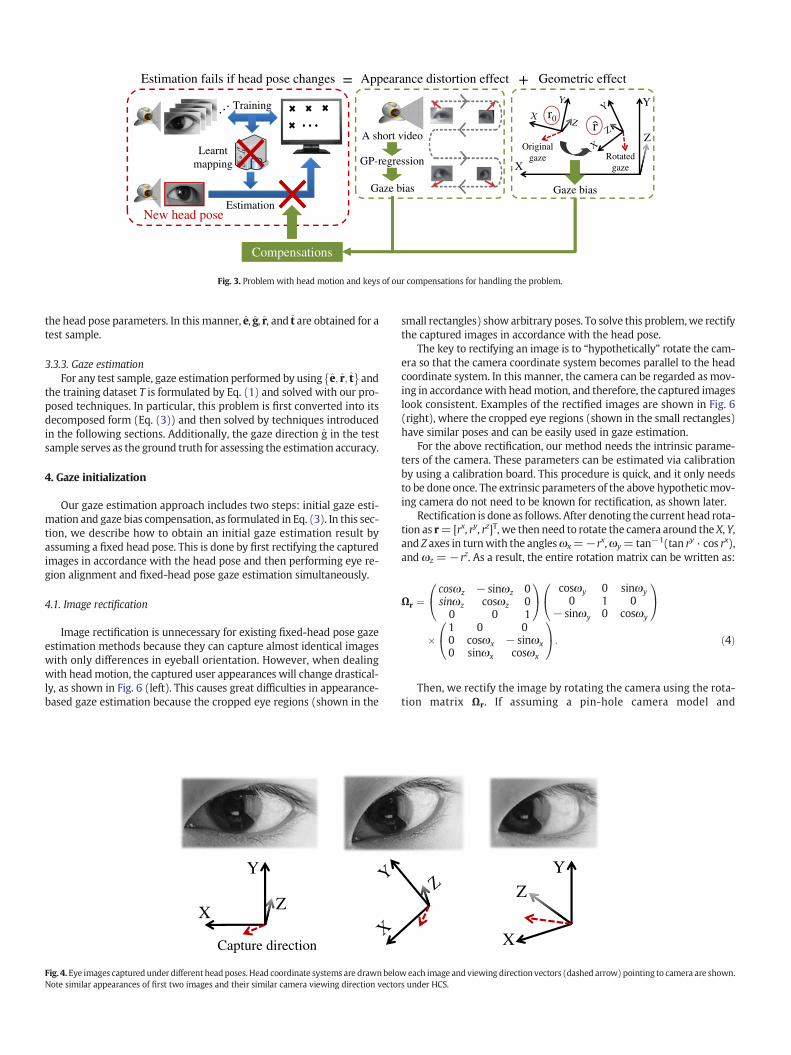
Image rectification is unnecessary for existing fixed-head pose gazeestimation methods because they can capture almost identical imageswith only differences in eyeball orientation. However, when dealingwith headmotion, the captured user appearances will change drastical-ly, as shown in Fig. 6 (left). This causes great difficulties in appearance-based gaze estimation because the cropped eye regions (shown in the
X
Y
Z
Capture direction
Fig. 4.Eye images capturedunder different headposes. Head coordinate systems are drawnbeloNote similar appearances of first two images and their similar camera viewing direction vecto
small rectangles) show arbitrary poses. To solve this problem,we rectifythe captured images in accordance with the head pose.
The key to rectifying an image is to “hypothetically” rotate the cam-era so that the camera coordinate system becomes parallel to the headcoordinate system. In this manner, the camera can be regarded as mov-ing in accordancewith headmotion, and therefore, the captured imageslook consistent. Examples of the rectified images are shown in Fig. 6(right), where the cropped eye regions (shown in the small rectangles)have similar poses and can be easily used in gaze estimation.
For the above rectification, our method needs the intrinsic parame-ters of the camera. These parameters can be estimated via calibrationby using a calibration board. This procedure is quick, and it only needsto be done once. The extrinsic parameters of the above hypotheticmov-ing camera do not need to be known for rectification, as shown later.
Rectification is done as follows. After denoting the current head rota-tion as r=[rx, ry, rz]T, we then need to rotate the camera around the X, Y,and Z axes in turnwith the anglesωx=−rx,ωy=tan−1(tan ry · cos rx),and ωz =−rz. As a result, the entire rotation matrix can be written as:
Ωr ¼cosωz − sinωz 0sinωz cosωz 00 0 1
0@
1A cosωy 0 sinωy
0 1 0− sinωy 0 cosωy
0@
1A
�1 0 00 cosωx − sinωx0 sinωx cosωx
0@
1A: ð4Þ
Then, we rectify the image by rotating the camera using the rota-tion matrix Ωr. If assuming a pin-hole camera model and
X
Y
Z
weach image andviewing direction vectors (dashed arrow) pointing to camera are shown.rs under HCS.
X
Y
Z
World coordinate system
0
Original gazeRotated
gazeRotations
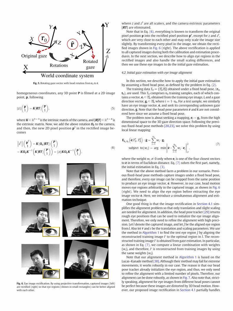
Fig. 5. Rotating gaze vector with head rotation from r0 to r.
homogeneous coordinates, any 3D point P is filmed at a 2D imagepoint, p, following
zk k p1
� �¼ K RT½ � P
1
� �; ð5Þ
whereK∈ℝ3 × 3 is the intrinsicmatrix of the camera, and [R|T]∈ℝ3 × 4 isthe extrinsic matrix. Now, we add the above rotation Ωr to the camera,and then, the new 2D pixel position p† in the rectified image be-comes
z† p†
1
� �¼ K Ωr RT½ �ð Þ P
1
� �¼ KΩrK
−1 K RT½ � P1
� �� �¼ zk kKΩrK
−1 p1
� �;
ð6Þ
Fig. 6. Eye image rectification. By using projective transformation, captured images (left)are rectified (right) so that eye regions (shown in small rectangles) can be better alignedwith each other.
where z and z† are all scalers, and the camera extrinsic parameters[RT] are eliminated.
Note that in Eq. (6), everything is known to transform the originalpixel position p into the rectified pixel position p†, except for z and z†,which are very close to each other and may only scale the image sizeslightly. By transforming every pixel in the image, we obtain the recti-fied images shown in Fig. 6 (right). The above rectification is appliedto all captured images during both the calibration and estimation proce-dures. In the next section, we describe how to align eye regions in therectified images and also handle the small scaling differences, andthen we use these eye images to do the initial gaze estimation.
4.2. Initial gaze estimation with eye image alignment
In this section, we describe how to apply the initial gaze estimationby assuming a fixed head pose, as defined by the problem in Eq. (2).
The training data T0 = {T0e,T0g} obtained under a fixed head pose, (r0,t0), are used. This T0 comprises n0 training samples, each of which con-tains a vector, ei∈ T0
e, obtained from the training eye image, Ii and a gazedirection vector, gi ∈ T0
g, where i=1⋯n0. For a test sample, we similarlyhave an eye image vector, e, and seek its corresponding unknown gazedirection, g. Note that the head pose parameters r and t are not consid-ered here since we assume a fixed head pose.
The problem now is about seeking a mapping, ei ↦ gi, from the highdimensional space to the 3D gaze direction space. Following the previ-ous fixed-head pose methods [20,23], we solve this problem by usinglocal linear mapping:
Er0 ;t0
ejTe
0; Tg0
�: g ¼
Xn0i¼1
wi � gi
subject to wif g ¼ arg min e−Xn0i¼1
wi � ei2
F
;
ð7Þ
where the weightwi ≠ 0 only when ei is one of the four closest vectorsto e in terms of Euclidean distance. Eq. (7) solves the first part, namely,the initial estimation in Eq. (3).
Note that the above method faces a problem in our scenario. Previ-ous fixed-head pose methods capture images under a fixed head pose,and therefore, every eye image can be cropped from the same positionto produce an eye image vector, e. However, in our case, head motionmoves eye regions arbitrarily in the captured image, as shown in Fig. 6(right). We need to align the eye region before extracting the eyeimage vector e. Here, we introduce a simultaneous alignment and esti-mation technique.
One good thing is that the image rectification in Section 4.1 sim-plifies the alignment problem so that only translation and slight scalingare needed for alignment. In addition, the head pose tracker [29] returnsrough eye positions that can be used to initialize the eye image align-ment. Therefore, we only need to refine the alignment with high preci-sion. Let I denote the captured image, and let J be the aligned eye regionfrom I. Also let τ and s be the translation and scaling parameters.We usethe method in Algorithm 1 to find the test eye region J by aligning thereconstructed training image I′ to the optimal region in I. The recon-structed training image I′ is obtained fromgaze estimation. In particular,as shown in Eq. (7), we compute a linear combination with weights{wi}, and therefore, I′ is reconstructed from training images by usingthe same weights {wi}.
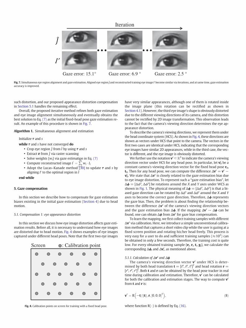
Note that our alignment method in Algorithm 1 is based on theLucas–Kanademethod [30]. Although theirmethodmay fail for extrememovements, it works robustly in our case. The reason is that our headpose tracker already initializes the eye region, and thus, we only needto refine the alignment with a limited number of pixels. Therefore, ouralignment can be done robustly, as shown in Fig. 7. Also note that, strict-ly speaking, alignment for eye images from different head poses cannotbe perfect because these images are distorted by 3D headmotion. How-ever, our proposed image rectification in Section 4.1 partially handles
… …
Gaze error: 15.1° Gaze error: 6.9 ° Gaze error: 2.5 °
Iteration
Fig. 7. Simultaneous eye region alignment and gaze estimation. Aligned eye region J and reconstructed training eye image I′ become similar via iterations, and at same time, gaze estimationaccuracy is improved.
such distortion, and our proposed appearance distortion compensationin Section 5.1 handles the remaining effect.
Overall, the proposed iterative method refines both gaze estimationand eye image alignment simultaneously and eventually obtains thebest solution to Eq. (7) as the initial fixed-head pose gaze estimation re-sult. An example of this procedure is shown in Fig. 7.
Algorithm 1. Simultaneous alignment and estimation
Initialize τ and s
while τ and s have not converged do• Crop eye region J from I by using τ and s• Extract e from J via raster scanning• Solve weights {wi} via gaze estimation in Eq. (7)• Compute reconstructed image I′ ¼ ∑
n0
i¼1wi � Ii
• Adopt the Lucas–Kanade method [30] to update τ and s byaligning I′ to the optimal region in I
end while
5. Gaze compensation
In this section we describe how to compensate for gaze estimationbiases existing in the initial gaze estimation (Section 4) due to headmotion.
5.1. Compensation 1: eye appearance distortion
In this sectionwe discuss how eye image distortion affects gaze esti-mation results. Before all, it is necessary to understand how eye imagesare distorted due to head motion. Fig. 4 shows examples of eye imagescaptured under different head poses. Note that the first two eye images
Screen : Calibration point
Fig. 8. Calibration points on screen for training with a fixed head pose.
have very similar appearances, although one of them is rotated insidethe image plane (this rotation can be rectified as shown inSection 4.1). However, the third eye image's shape is obviously distorteddue to the different viewing directions of its camera, and this distortioncannot be rectified by 2D image transformation. This observation leadsto the fact that the camera's viewing direction determines the eye ap-pearance distortion.
To describe the camera's viewingdirections,we represent themunderthe head coordinate system (HCS). As shown in Fig. 4, these directions areshown as vectors under HCS that point to the camera. The vectors in thefirst two cases are identical under HCS, indicating that the correspondingeye images have similar 2D appearances, while in the third case, the vec-tor is different, and the eye image is obviously distorted.
We further use the notation vc∈ℝ3 to indicate the camera's viewingdirection vector under HCS for any head pose. In particular, let v0c be aconstant camera's viewing direction vector for the fixed head pose r0,t0. Then for any head pose, we can compute the difference Δvc = vc −v0c . We state that Δvc is closely related to the gaze estimation bias dueto eye image distortion. To represent such a “gaze estimation bias”, letΔϕ = [Δϕx, Δϕy] be rotations around the X and Y axes under WCS asshown in Fig. 1. The physical meaning of Δϕ = [Δϕx, Δϕy] is that a bi-ased gaze direction can be rotated by Δϕx and Δϕy around the X and Yaxes to become the correct gaze direction. Therefore, Δϕ representsthe gaze bias. Then, the problem is about finding the relationship be-tween the difference Δvc of the camera's viewing direction vectorsand the gaze estimation bias Δϕ. If the mapping Δvc ↦ Δϕ can befound, one can obtain Δϕ from Δvc for gaze bias compensation.
To learn themapping, we first collect training sampleswith differentΔvc via calibration. Here, we introduce a simple unconventional calibra-tionmethod that captures a short video clip while the user is gazing at afixed screen position and rotating his/her head freely. This process isvery easy for a user to do and sufficient training samples (≈102) canbe obtained in only a few seconds. Therefore, the training cost is quitelow. For every obtained training sample {ei, ri, ti, gi}, we calculate thecorresponding Δϕi and Δvic, as mentioned above.
5.1.1. Calculation of Δvc and ΔϕThe camera's viewing direction vector vc under HCS is deter-
mined by both head translation t = [tx, ty, tz]T and head rotation r =[rx, ry, rz]T. Both t and r can be obtained by the head pose tracker in realtime during calibration and estimation. Therefore, vc can be calculatedfor both the calibration and estimation stages. The way to compute vc
from t and r is:
vc ¼ R −t= tk k; r; 0;0;0½ �T �
; ð8Þ
where function R(·) is defined by Eq. (16).
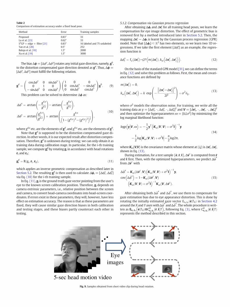
Table 2Comparison of estimation accuracy under a fixed head pose.
Method Error Training samples
Proposed 0.83° 33Lu et al. [23] 0.62° 33S3GP + edge + filter [21] 0.83° 16 labeled and 75 unlabeledTan et al. [20] 0.5° 252Baluja et al. [18] 1.5° 2000Xu et al. [19] 1.5° 3000
The biasΔϕ=[Δϕx,Δϕy] rotates any initial gaze direction, namely, g0,to the distortion compensated gaze direction denoted as gd. Thus, Δϕ =[Δϕx, Δϕy] must fulfill the following relation.
gd ¼cosΔϕy 0 sinΔϕy
0 1 0− sinΔϕy 0 cosΔϕy
0@
1A 1 0 0
0 cosΔϕx − sinΔϕx
0 sinΔϕx cosΔϕx
0@
1Ag0: ð9Þ
This problem can be solved to determine Δϕ as:
Δϕx ¼ arctan − gd;y
gd;z
!− arctan − g0;y
g0;z
!;
Δϕy ¼ arctangd;xi
gd;z
!þ arctan
g0;x
1− g0;x� �2− gd;y
� �2 �12
0B@
1CA;
ð10Þ
where gd,x etc. are the elements of gd, and g0,x etc. are the elements of g0.Note that gd is supposed to be the distortion compensated gaze di-
rection. In otherwords, it is our expected result after distortion compen-sation. Therefore, gd is unknown during testing; we can only obtain it astraining data during calibration stage. In particular, for the i-th trainingsample, we compute gid by rotating gi in accordancewith head rotationsri and r0:
gdi ¼ R gi; ri; r0ð Þ; ð11Þ
which applies an inverse geometric compensation as described later inSection 5.2. The resulting gid is then used to calculate Δϕi = [Δϕi
x, Δϕiy]
via Eq. (10) for the i-th training sample.In Eq. (11), gi is the ground truth gaze vector pointing from the user's
eye to the known screen calibration position. Therefore, gi depends oncamera extrinsic parameters, i.e., relative position between the screenand camera, to convert head-camera coordinates into head-screen coor-dinates. If errors exist in these parameters, theywill, however, have lesseffect on estimation accuracy. The reason is that as these parameters arefixed, they will cause similar gaze direction biases in both calibrationand testing stages, and these biases partly counteract each other intesting.
5-sec head motion video
Eyeimage
Fig. 9. Samples obtained from short
5.1.2. Compensation via Gaussian process regressionAfter obtaining Δϕi and Δvic for all training head poses, we learn the
compensation for eye image distortion. The effect of geometric bias isremoved first by a method introduced later in Section 5.2. Then, themapping Δvic ↦ Δϕi is learnt by the Gaussian process regression (GPR)model. Note that {Δϕi} ∈ ℝ2 has two elements, so we learn two 1D re-gressions. If we take the first element {Δϕi
x} as an example, the regres-sion function is
Δϕxi ¼ fx Δvci
� �∼GP m Δvci
� �; kw Δvci ;Δv
cj
� �: ð12Þ
On the basis of the standardGPRmodel [31],we can define the termsin Eq. (12) and solve this problem as follows. First, themean and covari-ance functions are defined by
m Δvci� � ¼ 0;
kw Δvci ;Δvcj
�¼ k exp −
Δvci−Δvcj 2
2l2
0B@
1CAþ σ2δij;
ð13Þ
where σ2 models the observation noise. For training, we write all thetraining data as y = [Δϕ1
x, ⋯, Δϕix, ⋯, Δϕn
x]T and V = [Δv1c , ⋯, Δvic, ⋯, Δvnc]Tand then optimize the hyperparameters ω = {k,l,σ2} by minimizing thelog marginal likelihood function:
logpy V ;ω��� �
¼ −12yT Kω V ;Vð Þ þ σ2I �−1
y
−12log Kω V ;Vð Þ þ σ2I��� ���−n
2log2π;
ð14Þ
whereKω(V,V) is the covariancematrixwhose element at (i,j) isΔvic,Δvjc,shown in Eq. (13).
During estimation, for a test sample e; r; t� �
,Δvc is computed from rand t first. Then, with the optimized hyperparameters, we predict Δϕ
x
from Δvc with
Δϕx ¼ Kω Δvc;V� �
Kω V ;Vð Þ þ σ2I �−1
y;
cov Δϕx �
¼ 1−Kω Δvc;V� �
Kω V ;Vð Þ þ σ2I �−1
Kω V ;Δvc� �
:
ð15Þ
After obtaining both Δϕxand Δϕ
y, we use them to compensate for
gaze estimation bias due to eye appearance distortion. This is done byrotating the initially estimated gaze vector Er0 ;t0 e T0j Þð in Section 4.2around the X and Y axeswithΔϕ
xandΔϕ
y. Thewhole procedure iswrit-
ten as Er0;t0 e T0j Þ⊗CDr0 ;t0 r; t� ��T �
, following Eq. (3), where CDr0 ;t0 r; t� ��TÞ
represents the method described in this section.
s
video clip during head rotation.
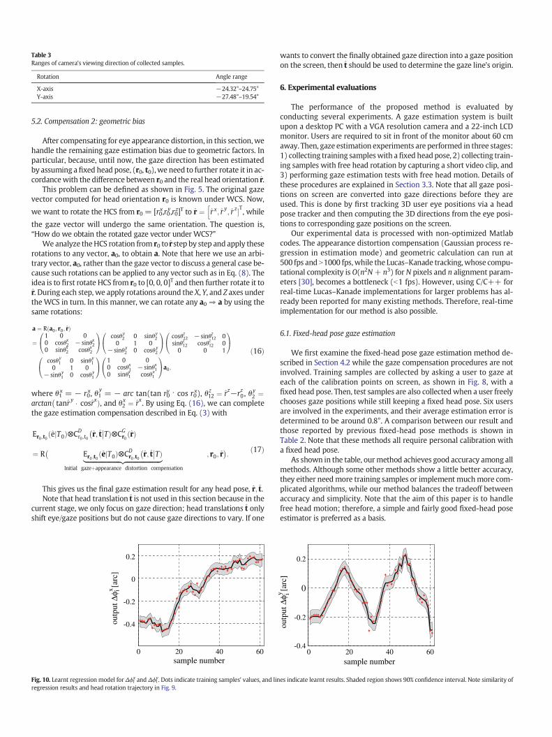
Table 3Ranges of camera's viewing direction of collected samples.
Rotation Angle range
X-axis −24.32°–24.75°Y-axis −27.48°–19.54°
5.2. Compensation 2: geometric bias
After compensating for eye appearance distortion, in this section,wehandle the remaining gaze estimation bias due to geometric factors. Inparticular, because, until now, the gaze direction has been estimatedby assuming a fixed head pose, (r0, t0),we need to further rotate it in ac-cordancewith the difference between r0 and the real head orientation r.
This problem can be defined as shown in Fig. 5. The original gazevector computed for head orientation r0 is known under WCS. Now,
we want to rotate the HCS from r0 = [r0x,r0y,r0z]T to r ¼ r x; r y; r z�T
h, while
the gaze vector will undergo the same orientation. The question is,“How do we obtain the rotated gaze vector under WCS?”
Weanalyze theHCS rotation from r0 to rstep by step and apply theserotations to any vector, a0, to obtain a. Note that here we use an arbi-trary vector, a0, rather than the gaze vector to discuss a general case be-cause such rotations can be applied to any vector such as in Eq. (8). Theidea is to first rotate HCS from r0 to [0, 0, 0]T and then further rotate it tor. During each step, we apply rotations around the X, Y, and Z axes underthe WCS in turn. In this manner, we can rotate any a0 ⇒ a by using thesame rotations:
a ¼ R a0; r0; rð Þ
¼1 0 00 cosθx2 − sinθx20 sinθx2 cosθx2
0@
1A cosθy
2 0 sinθy2
0 1 0− sinθy
2 0 cosθy2
0@
1A cosθz12 − sinθz12 0
sinθz12 cosθz12 00 0 1
0@
1A
cosθy1 0 sinθy
10 1 0
− sinθy1 0 cosθy
1
0@
1A 1 0 0
0 cosθx1 − sinθx10 sinθx1 cosθx
1
0@
1Aa0;
ð16Þ
where θ1x = − r0x, θ1
y= − arc tan(tan r0
y ⋅ cos r0x), θ z12 ¼ rz−rz0 , θ
y2 ¼
arctan tanr y � cosrxÞ�, and θx
2 ¼ rx . By using Eq. (16), we can completethe gaze estimation compensation described in Eq. (3) with
Er0 ;t0 eð jT0Þ⊗CDr0 ;t0 r; t� ��TÞ⊗CG
r0 rð Þ
¼ R�
Er0 ;t0 eð jT0Þ⊗CDr0 ;t0 r; t� ��TÞ|fflfflfflfflfflfflfflfflfflfflfflfflfflfflfflfflfflfflfflfflfflffl{zfflfflfflfflfflfflfflfflfflfflfflfflfflfflfflfflfflfflfflfflfflffl}
Initial gazeþappearance distortion compensation
; r0; r�:
ð17Þ
This gives us the final gaze estimation result for any head pose, r; t.Note that head translation t is not used in this section because in the
current stage, we only focus on gaze direction; head translations t onlyshift eye/gaze positions but do not cause gaze directions to vary. If one
0 20 40 60
-0.4
-0.2
0
0.2
sample number
outp
ut Δ
φ i [
arc]
x
Fig. 10. Learnt regression model for Δϕix and Δϕi
y. Dots indicate training samples' values, and linregression results and head rotation trajectory in Fig. 9.
wants to convert the finally obtained gaze direction into a gaze positionon the screen, then t should be used to determine the gaze line's origin.
6. Experimental evaluations
The performance of the proposed method is evaluated byconducting several experiments. A gaze estimation system is builtupon a desktop PC with a VGA resolution camera and a 22-inch LCDmonitor. Users are required to sit in front of the monitor about 60 cmaway. Then, gaze estimation experiments are performed in three stages:1) collecting training sampleswith afixed headpose, 2) collecting train-ing samples with free head rotation by capturing a short video clip, and3) performing gaze estimation tests with free head motion. Details ofthese procedures are explained in Section 3.3. Note that all gaze posi-tions on screen are converted into gaze directions before they areused. This is done by first tracking 3D user eye positions via a headpose tracker and then computing the 3D directions from the eye posi-tions to corresponding gaze positions on the screen.
Our experimental data is processed with non-optimized Matlabcodes. The appearance distortion compensation (Gaussian process re-gression in estimation mode) and geometric calculation can run at500 fps and N1000 fps,while the Lucas–Kanade tracking,whose compu-tational complexity is O(n2N+ n3) for N pixels and n alignment param-eters [30], becomes a bottleneck (b1 fps). However, using C/C++ forreal-time Lucas–Kanade implementations for larger problems has al-ready been reported for many existing methods. Therefore, real-timeimplementation for our method is also possible.
6.1. Fixed-head pose gaze estimation
We first examine the fixed-head pose gaze estimation method de-scribed in Section 4.2 while the gaze compensation procedures are notinvolved. Training samples are collected by asking a user to gaze ateach of the calibration points on screen, as shown in Fig. 8, with afixed head pose. Then, test samples are also collectedwhen a user freelychooses gaze positions while still keeping a fixed head pose. Six usersare involved in the experiments, and their average estimation error isdetermined to be around 0.8°. A comparison between our result andthose reported by previous fixed-head pose methods is shown inTable 2. Note that these methods all require personal calibration witha fixed head pose.
As shown in the table, ourmethod achieves good accuracy among allmethods. Although some other methods show a little better accuracy,they either needmore training samples or implement muchmore com-plicated algorithms, while our method balances the tradeoff betweenaccuracy and simplicity. Note that the aim of this paper is to handlefree head motion; therefore, a simple and fairly good fixed-head poseestimator is preferred as a basis.
0 20 40 60-0.4
-0.2
0
0.2
sample number
outp
ut Δ
φ i [ar
c]
y
es indicate learnt results. Shaded region shows 90% confidence interval. Note similarity of
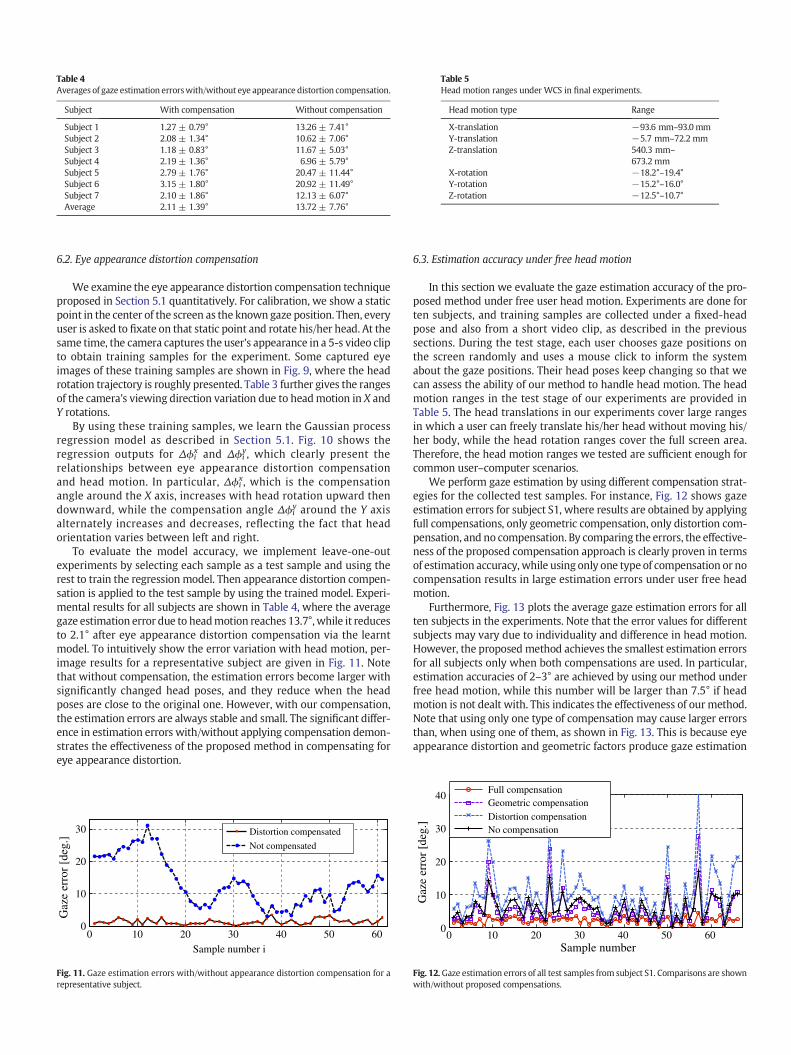
Table 4Averages of gaze estimation errorswith/without eye appearance distortion compensation.
Subject With compensation Without compensation
Subject 1 1.27 ± 0.79° 13.26 ± 7.41°Subject 2 2.08 ± 1.34° 10.62 ± 7.06°Subject 3 1.18 ± 0.83° 11.67 ± 5.03°Subject 4 2.19 ± 1.36° 6.96 ± 5.79°Subject 5 2.79 ± 1.76° 20.47 ± 11.44°Subject 6 3.15 ± 1.80° 20.92 ± 11.49°Subject 7 2.10 ± 1.86° 12.13 ± 6.07°Average 2.11 ± 1.39° 13.72 ± 7.76°
Table 5Head motion ranges under WCS in final experiments.
Head motion type Range
X-translation −93.6 mm–93.0mmY-translation −5.7 mm–72.2 mmZ-translation 540.3 mm–
673.2 mmX-rotation −18.2°–19.4°Y-rotation −15.2°–16.0°Z-rotation −12.5°–10.7°
6.2. Eye appearance distortion compensation
We examine the eye appearance distortion compensation techniqueproposed in Section 5.1 quantitatively. For calibration, we show a staticpoint in the center of the screen as the known gaze position. Then, everyuser is asked to fixate on that static point and rotate his/her head. At thesame time, the camera captures the user's appearance in a 5-s video clipto obtain training samples for the experiment. Some captured eyeimages of these training samples are shown in Fig. 9, where the headrotation trajectory is roughly presented. Table 3 further gives the rangesof the camera's viewing direction variation due to headmotion in X andY rotations.
By using these training samples, we learn the Gaussian processregression model as described in Section 5.1. Fig. 10 shows theregression outputs for Δϕi
x and Δϕiy, which clearly present the
relationships between eye appearance distortion compensationand head motion. In particular, Δϕi
x, which is the compensationangle around the X axis, increases with head rotation upward thendownward, while the compensation angle Δϕi
y around the Y axisalternately increases and decreases, reflecting the fact that headorientation varies between left and right.
To evaluate the model accuracy, we implement leave-one-outexperiments by selecting each sample as a test sample and using therest to train the regression model. Then appearance distortion compen-sation is applied to the test sample by using the trained model. Experi-mental results for all subjects are shown in Table 4, where the averagegaze estimation error due to headmotion reaches 13.7°,while it reducesto 2.1° after eye appearance distortion compensation via the learntmodel. To intuitively show the error variation with head motion, per-image results for a representative subject are given in Fig. 11. Notethat without compensation, the estimation errors become larger withsignificantly changed head poses, and they reduce when the headposes are close to the original one. However, with our compensation,the estimation errors are always stable and small. The significant differ-ence in estimation errors with/without applying compensation demon-strates the effectiveness of the proposed method in compensating foreye appearance distortion.
0 10 20 30 40 50 600
10
20
30
Sample number i
Gaz
e er
ror
[deg
.]
Distortion compensated
Not compensated
Fig. 11. Gaze estimation errors with/without appearance distortion compensation for arepresentative subject.
6.3. Estimation accuracy under free head motion
In this section we evaluate the gaze estimation accuracy of the pro-posed method under free user head motion. Experiments are done forten subjects, and training samples are collected under a fixed-headpose and also from a short video clip, as described in the previoussections. During the test stage, each user chooses gaze positions onthe screen randomly and uses a mouse click to inform the systemabout the gaze positions. Their head poses keep changing so that wecan assess the ability of our method to handle head motion. The headmotion ranges in the test stage of our experiments are provided inTable 5. The head translations in our experiments cover large rangesin which a user can freely translate his/her head without moving his/her body, while the head rotation ranges cover the full screen area.Therefore, the head motion ranges we tested are sufficient enough forcommon user–computer scenarios.
We perform gaze estimation by using different compensation strat-egies for the collected test samples. For instance, Fig. 12 shows gazeestimation errors for subject S1, where results are obtained by applyingfull compensations, only geometric compensation, only distortion com-pensation, and no compensation. By comparing the errors, the effective-ness of the proposed compensation approach is clearly proven in termsof estimation accuracy, while using only one type of compensation or nocompensation results in large estimation errors under user free headmotion.
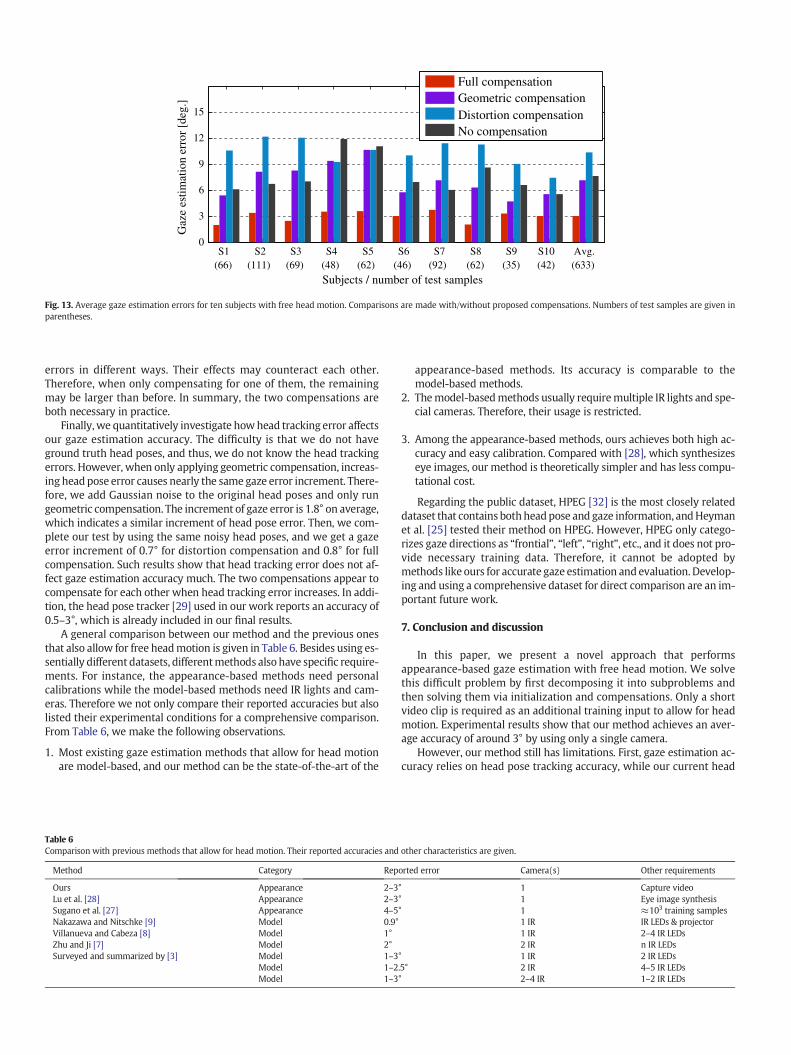
Furthermore, Fig. 13 plots the average gaze estimation errors for allten subjects in the experiments. Note that the error values for differentsubjects may vary due to individuality and difference in head motion.However, the proposed method achieves the smallest estimation errorsfor all subjects only when both compensations are used. In particular,estimation accuracies of 2–3° are achieved by using our method underfree head motion, while this number will be larger than 7.5° if headmotion is not dealt with. This indicates the effectiveness of our method.Note that using only one type of compensation may cause larger errorsthan, when using one of them, as shown in Fig. 13. This is because eyeappearance distortion and geometric factors produce gaze estimation
0 10 20 30 40 50 600
10
20
30
40
Sample number
Gaz
e er
ror
[deg
.]
Full compensationGeometric compensationDistortion compensationNo compensation
Fig. 12.Gaze estimation errors of all test samples from subject S1. Comparisons are shownwith/without proposed compensations.
(66) (111) (69) (48) (62) (46) (92) (62) (35) (42) (633)S1 S2 S3 S4 S5 S6 S7 S8 S9 S10 Avg.
0
3
6
9
12
15
Subjects / number of test samples
Gaz
e es
timat
ion
erro
r [d
eg.]
Full compensationGeometric compensationDistortion compensationNo compensation
Fig. 13. Average gaze estimation errors for ten subjects with free head motion. Comparisons are made with/without proposed compensations. Numbers of test samples are given inparentheses.
errors in different ways. Their effects may counteract each other.Therefore, when only compensating for one of them, the remainingmay be larger than before. In summary, the two compensations areboth necessary in practice.
Finally,we quantitatively investigate howhead tracking error affectsour gaze estimation accuracy. The difficulty is that we do not haveground truth head poses, and thus, we do not know the head trackingerrors. However, when only applying geometric compensation, increas-ing headpose error causes nearly the same gaze error increment. There-fore, we add Gaussian noise to the original head poses and only rungeometric compensation. The increment of gaze error is 1.8° on average,which indicates a similar increment of head pose error. Then, we com-plete our test by using the same noisy head poses, and we get a gazeerror increment of 0.7° for distortion compensation and 0.8° for fullcompensation. Such results show that head tracking error does not af-fect gaze estimation accuracy much. The two compensations appear tocompensate for each other when head tracking error increases. In addi-tion, the head pose tracker [29] used in our work reports an accuracy of0.5–3°, which is already included in our final results.
A general comparison between our method and the previous onesthat also allow for free headmotion is given in Table 6. Besides using es-sentially different datasets, differentmethods also have specific require-ments. For instance, the appearance-based methods need personalcalibrations while the model-based methods need IR lights and cam-eras. Therefore we not only compare their reported accuracies but alsolisted their experimental conditions for a comprehensive comparison.From Table 6, we make the following observations.
1. Most existing gaze estimation methods that allow for head motionare model-based, and our method can be the state-of-the-art of the
Table 6Comparison with previous methods that allow for head motion. Their reported accuracies and
Method Category Rep
Ours Appearance 2–3Lu et al. [28] Appearance 2–3Sugano et al. [27] Appearance 4–5Nakazawa and Nitschke [9] Model 0.9°Villanueva and Cabeza [8] Model 1°Zhu and Ji [7] Model 2°Surveyed and summarized by [3] Model 1–3
Model 1–2Model 1–3
appearance-based methods. Its accuracy is comparable to themodel-based methods.
2. Themodel-basedmethods usually requiremultiple IR lights and spe-cial cameras. Therefore, their usage is restricted.
3. Among the appearance-based methods, ours achieves both high ac-curacy and easy calibration. Compared with [28], which synthesizeseye images, our method is theoretically simpler and has less compu-tational cost.
Regarding the public dataset, HPEG [32] is the most closely relateddataset that contains bothheadpose and gaze information, andHeymanet al. [25] tested their method on HPEG. However, HPEG only catego-rizes gaze directions as “frontial”, “left”, “right”, etc., and it does not pro-vide necessary training data. Therefore, it cannot be adopted bymethods like ours for accurate gaze estimation and evaluation. Develop-ing and using a comprehensive dataset for direct comparison are an im-portant future work.
7. Conclusion and discussion
In this paper, we present a novel approach that performsappearance-based gaze estimation with free head motion. We solvethis difficult problem by first decomposing it into subproblems andthen solving them via initialization and compensations. Only a shortvideo clip is required as an additional training input to allow for headmotion. Experimental results show that our method achieves an aver-age accuracy of around 3° by using only a single camera.
However, our method still has limitations. First, gaze estimation ac-curacy relies on head pose tracking accuracy, while our current head
other characteristics are given.
orted error Camera(s) Other requirements
° 1 Capture video° 1 Eye image synthesis° 1 ≈103 training samples
1 IR IR LEDs & projector1 IR 2–4 IR LEDs2 IR n IR LEDs
° 1 IR 2 IR LEDs.5° 2 IR 4–5 IR LEDs° 2–4 IR 1–2 IR LEDs
pose tracker performs badly with large head rotation (N45°) and facesproblems under varying illumination. Second, individual calibrationneeds to be done for every user before estimation. This is a commonproblem for appearance-based methods that is expected to be handledin the future.
Finally, the experimental validation in this paper uses our owndatasetbecause existing dataset cannot fulfill the requirements for differentmethods. Therefore, a good goal for future work is to design and collectmore general gaze estimationdatasets for direct comparisonbetweendif-ferent methods.
References
[1] G. Underwood, Cognitive Processes in Eye Guidance, Oxford University Press, USA,2005.
[2] L. Young, D. Sheena, Survey of eye movement recording methods, Behav. Res.Methods 7 (1975) 397–429.
[3] D. Hansen, Q. Ji, In the eye of the beholder: a survey of models for eyes and gaze,IEEE Trans. Pattern Anal. Mach. Intell. 32 (2010) 478–500.
[4] C. Morimoto, M. Mimica, Eye gaze tracking techniques for interactive applications,Comput. Vis. Image Underst. 98 (2005) 4–24.
[5] D.H. Yoo, M.J. Chung, A novel non-intrusive eye gaze estimation using cross-ratiounder large head motion, Comput. Vis. Image Underst. 98 (2005) 25–51.
[6] E. Guestrin, M. Eizenman, General theory of remote gaze estimation using thepupil center and corneal reflections, IEEE Trans. Biomed. Eng. 53 (2006)1124–1133.
[7] Z. Zhu, Q. Ji, Novel eye gaze tracking techniques under natural headmovement, IEEETrans. Biomed. Eng. 54 (2007) 2246–2260.
[8] A. Villanueva, R. Cabeza, A novel gaze estimation system with one calibration point,IEEE Trans. Syst. Man Cybern. B Cybern. 38 (2008) 1123–1138.
[9] A. Nakazawa, C. Nitschke, Point of gaze estimation through corneal surface reflec-tion in an active illumination environment, ECCV, 2012, pp. 159–172.
[10] R. Valenti, T. Gevers, Accurate eye center location and tracking using isophote curva-ture, Proceedings of IEEE Conference on Computer Vision and Pattern Recognition(CVPR 2008), 2008, pp. 1–8.
[11] R. Valenti, N. Sebe, T. Gevers, Combining head pose and eye location information forgaze estimation, IEEE Trans. Image Process. 21 (2012) 802–815.
[12] J. Wang, E. Sung, R. Venkateswarlu, Eye gaze estimation from a single image of oneeye, Proceedings of the 9th IEEE International Conference on Computer Vision (ICCV2009), 2003, pp. 136–143.
[13] D. Beymer, M. Flickner, Eye gaze tracking using an active stereo head, Proceedings ofIEEE Conference on Computer Vision and Pattern Recognition (CVPR 2003), 2003,pp. 451–458.
[14] X. Brolly, J. Mulligan, Implicit calibration of a remote gaze tracker, Proceedings ofIEEE Conference on Computer Vision and Pattern Recognition Workshop (CVPRW2004), 2004, p. 134.
[15] T. Nagamatsu, J. Kamahara, N. Tanaka, 3D gaze tracking with easy calibration usingstereo cameras for robot and human communication, Proceedings of the 17th IEEEInternational Symposium on Robot and Human Interactive Communication(RO-MAN 2008), 2008, pp. 59–64.
[16] J. Kang, M. Eizenman, E. Guestrin, E. Eizenman, Investigation of the cross-ratiosmethod for point-of-gaze estimation, IEEE Trans. Biomed. Eng. 55 (2008)2293–2302.
[17] J. Chen, Q. Ji, Probabilistic gaze estimation without active personal calibration, CVPR,2011, pp. 609–616.
[18] S. Baluja, D. Pomerleau, Non-intrusive gaze tracking using artificial neural networks,Proceedings of Advances in Neural Information Processing Systems, volume 6, 1994,pp. 753–760.
[19] L.Q. Xu, D. Machin, P. Sheppard, A novel approach to real-time non-intrusive gazefinding, Proceedings of British Machine Vision Conference (BMVC 1998), 1998,pp. 428–437.
[20] K. Tan, D. Kriegman, N. Ahuja, Appearance-based eye gaze estimation, Proceedingsof the 6th IEEE Workshop on Applications of Computer Vision (WACV 2002),2002, pp. 191–195.
[21] O. Williams, A. Blake, R. Cipolla, Sparse and semi-supervised visual mapping withthe S3GP, Proceedings of IEEE Conference on Computer Vision and Pattern Recogni-tion (CVPR 2006), 2006, pp. 230–237.
[22] Y. Sugano, Y. Matsushita, Y. Sato, Calibration-free gaze sensing using saliency maps,Proceedings of IEEE Conference on Computer Vision and Pattern Recognition (CVPR2010), 2010, pp. 2667–2674.
[23] F. Lu, Y. Sugano, T. Okabe, Y. Sato, Inferring human gaze from appearance via adap-tive linear regression, Proceedings of the 13th IEEE International Conference onComputer Vision (ICCV 2011)2011.
[24] H. Yamazoe, A. Utsumi, T. Yonezawa, S. Abe, Remote gaze estimationwith a single cam-era based on facial-feature tracking without special calibration actions, Proceedings ofthe 2008 Symposium on Eye Tracking Research and Applications, 2008, pp. 245–250.
[25] T. Heyman, V. Spruyt, L. Alessandro, 3d face tracking and gaze estimation using amonocular camera, Proceedings of the 2nd International Conference on Positioningand Context-Awareness2011.
[26] B.L. Nguyen, Y. Chahir, M. Molina, C. Tijus, F. Jouen, Eye gaze tracking with free headmovements using a single camera, Proceedings of the 2010 Symposium on Informa-tion and Communication Technology, 2010, pp. 108–113.
[27] Y. Sugano, Y. Matsushita, Y. Sato, H. Koike, An incremental learning method for un-constrained gaze estimation, Proceedings of the 10th European Conference on Com-puter Vision (ECCV 2008), 2008, pp. 656–667.
[28] F. Lu, Y. Sugano, T. Okabe, Y. Sato, Head pose-free appearance-based gaze sensing viaeye image synthesis, ICPR2012.
[29] faceAPI, http://www.seeingmachines.com/product/faceapi/2012.[30] S. Baker, I. Matthews, Lucas–Kanade 20 years on: a unifying framework, IJCV 56
(2004) 221–255.[31] C.E. Rasmussen, C.K.I. Williams, Gaussian Processes for Machine Learning, MIT Press,
2006.[32] S. Asteriadis, D. Soufleros, K. Karpouzis, S. Kollias, A natural head pose and eye gaze
dataset, Proceedings of the International Workshop on Affective-Aware VirtualAgents and Social Robots, 2009, pp. 1:1–1:4.