Lead-Free Wrought Copper Alloys for Bushings and …...Lead-Free Wrought Copper Alloys for Bushings...
26
4 Lead-Free Wrought Copper Alloys for Bushings and Sliding Elements Kai Weber and H.-A. Kuhn Wieland-Werke AG, Ulm, Germany 1. Introduction Components of copper and copper alloys are used in a wide range of applications in automobile manufacture and in machinery and plant construction. On the one hand, because of their high electrical conductivity, copper-based components are indispensable for the functionality of electrical and electronic units in motor vehicles and machines. On the other hand, they have a wide range of uses in the form of bushings and sliding elements. Bearings, bushings and sliding elements ensure transmission or conversion of the drive energy in machines, plants and in internal combustion engines. The installation situation of piston pin bore bushings in a combustion engine is pictured in Figure 1. Fig. 1. Installation situation of piston pin bore bushings. www.intechopen.com
Transcript of Lead-Free Wrought Copper Alloys for Bushings and …...Lead-Free Wrought Copper Alloys for Bushings...
4
Lead-Free Wrought Copper Alloys for Bushings and Sliding Elements
Kai Weber and H.-A. Kuhn Wieland-Werke AG, Ulm,
Germany
1. Introduction
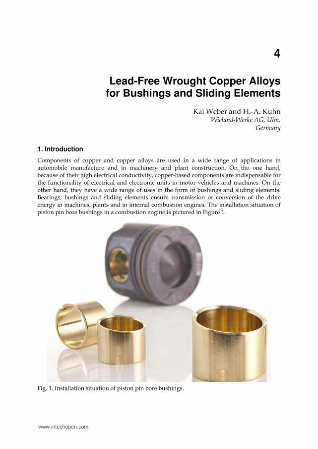
Components of copper and copper alloys are used in a wide range of applications in automobile manufacture and in machinery and plant construction. On the one hand, because of their high electrical conductivity, copper-based components are indispensable for the functionality of electrical and electronic units in motor vehicles and machines. On the other hand, they have a wide range of uses in the form of bushings and sliding elements. Bearings, bushings and sliding elements ensure transmission or conversion of the drive energy in machines, plants and in internal combustion engines. The installation situation of piston pin bore bushings in a combustion engine is pictured in Figure 1.
Fig. 1. Installation situation of piston pin bore bushings.
www.intechopen.com

Copper Alloys – Early Applications and Current Performance – Enhancing Processes
70
As a result of the increasing mechanical, tribological and thermal stresses to which the bearings in modern engines and plants are subjected, the materials used until now are increasingly reaching the limits of their stability under load. Wrought special brasses, multiphase tin-bronzes and nickel-tin-bronzes are the preferred metals.
Exactness of bushing dimensions made of wrapped strips or drawn tubes is realized by final machining. Beside the use of suited cutting tools and chose of appropriated machining parameters the productivity of chip removal depends also on the microstructure of the alloy. In customized special brasses lead forms a drop-like metallurgical phase which enables easy and economically machining of sliding elements like bushings in their final production stages. In use lead also improves lubrication behavior of sliding elements. The End-of-Life Vehicle Directive of the European Community intends to banish lead as an alloying element for metals. By minimizing the lead content in industrial products the legislator takes care in health of his residents. Manufacturer and supplier of bushings, bearings and sliding elements feel compelled to develop and offer lead-free materials.
Beside legislative demands on chemical compositions the development of new bushing materials is also driven by continuous improvements of engine performances. Bushings have to resist higher ignition points and cylinder pressures. Preferred copper-based wrought materials are special brasses, multiphase tin-bronzes and nickel-tin-bronzes. In addition lead-free substitutes have to meet requirements on economical machining. Due to a dramatic increase of copper prices the automotive industry asks for bushings made of less expensive metals. One technical solution to overcome materials costs is to replace sliding elements made of bulk materials by plated metal composites with only a thin wear resistant layer of copper alloy.
On the basis of a systematic analysis of the individual types of wear and damage mechanisms, this documentation will concentrate on the development of a new generation of lead-free brasses and tin-bronzes with intermetallics, copper-nickel-tin-alloys and roll clad composites made of spinoidally hardened bronzes. The development of wear resistant and thermally stable microstructures is discussed by assessing the roles of chemical elements forming metallurgical phases. Principles of process routes are explained. The resulting mechanical properties between room and elevated temperature and their thermal stabilities are presented by comparison with some older established brasses and bronzes. Wear resistance is evaluated by tribometer runs. Chip removal rates are compared to lead containing materials.
2. Wear and wear mechanisms
To allow the material of a wearing part to be adapted to the prevailing operating conditions, it is necessary to survey the elementary processes in the respective tribological system (Burwell, 1957/58). The numerous different types of stress to which the bushings and sliding elements are exposed first require a systematic analysis of the individual types of wear and damage mechanisms. The classification of the main wear mechanisms provided by Zum Gahr in Figure 2 will be used as a basis for this (Zum Gahr, 1988).
The lubricating film between a sliding element and the element on which it slides does not lead to a complete separation of the sliding surfaces in all operating states. The resultant mixed friction causes the bearings to be subjected to stress in the form of adhesion (fretting wear).
www.intechopen.com

Lead-Free Wrought Copper Alloys for Bushings and Sliding Elements
71
Fig. 2. Main wear mechanisms (Zum Gahr, 1988).
In the case of a plain bearing, this wear mechanism ultimately causes seizing of the shaft
and consequently total failure (Bartel et al., 2004). A directionally oriented microstructure of
the bearing material can decisively reduce its fretting tendency. Phases with body-centered
cubic and hexagonal lattice structures are considered to be structural constituents that offer
greater resistance to adhesion. On the other hand, structural elements with a face-centered
cubic structure are more susceptible to fretting corrosion. The legally required abandonment
of lead as an alloying element, responsible for improving the emergency running properties
of the sliding elements, has focused attention on the wearing properties of the individual
phase constituents.
Particles caused by dirt or abrasion can damage the running surface of the sliding element in
various ways by abrasion (scoring wear or grooving) (Figure 3). To reduce the consequences
of wear in the form of microcutting and microploughing, hardness and yield stress Rp0.2 of
the bearing material are significant factors. In addition, the occurrence of the mechanisms of
microfatigue and microcracking make its toughness properties important (Zum Gahr, 1992).
Consequently, a heterogeneous microstructure with hard phases incorporated in a ductile
matrix would be advantageous for the bearing material.
The frictional stress leads to the formation of particles and layers between the surfaces that
come into contact (tribochemical reaction). When they reach a critical thickness, the reaction
layers tend to undergo brittle spalling, with the consequent formation of wear particles
(Collenberg, 1991). However, such reaction layers are highly important for the operation of
sliding elements, since, as so-called tribofilms, they increase the resistance of the bearing
material to adhesion (Bartel et al., 2004).
www.intechopen.com

Copper Alloys – Early Applications and Current Performance – Enhancing Processes
72
Fig. 3. Material damage under abrasive wear (Zum Gahr, 1992).
The varying hydrodynamic lubricating film pressure within the bearing points causes the sliding layer to undergo alternating tensile/compressive stress. Cracking that occurs leads to surface distress of the bearing (fatigue wear). The material should therefore have a heterogeneous microstructure with a ductile matrix in order to have a high resistance to crack initiation and propagation.
In addition to the wear mechanisms, the sliding elements in internal combustion engines and in many machines and plants are exposed to thermal stress. This may lead to undesired changing of the microstructure and to stress relaxation of the component. The accompanying loss of strength and dimensional stability limits the operational reliability of the sliding elements. To increase the thermal stability of the microstructure, the proportion of phases with greater transformation activity should be limited. Furthermore, fine precipitates should reduce the extent of thermally induced stress relaxation of the sliding element.
3. Experimental procedures
3.1 Characterization of microstructure
Grains, grain boundaries and metallurgical phases were examined by optical light microscopy. Specimen preparation by immersion etching in a sulphuric acid solution of K2Cl2O7 was first described by Schrader (Schrader, 1941). The complete method was also reported in detail by Kuhn et al. (Kuhn et al., 2004) and Hofmann et al. (Hofmann et al., 2005).
3.2 Mechanical properties
Yield strength, ultimate tensile strength and ductility A5 were determined at room temperature in accordance with standard EN 10002 by Z100 (Zwick company). Mechanical
www.intechopen.com

Lead-Free Wrought Copper Alloys for Bushings and Sliding Elements
73
properties at elevated temperatures up to 400°C were examined by a Zmart.Pro tension test machine (ZwickRoell company) equipped with an irradiation furnace (Maytec company). Hardnesses at room temperature were measured by Brinell Hardness HB.
3.3 Tribological properties
When choosing a test method, the stress conditions actually occurring should be
approximated (Römer & Bartz, 1981; Czichos & Habig, 2003; Grün et al., 2007). Therefore,
the ring segment/disk modeling method was used for examining the adhesive wear
behavior of the bushing materials. These materials were represented by the ring segments.
A disk of 100Cr6 was operating as the counterpart of this setup. Implementing this type of
method as a fretting test allows the loading limit of the sliding material to be determined by
means of increasing the load in intervals. The ring segment/disk arrangement was chosen to
initiate conditions in real bearing assemblies as described by Pucher et. al. (Pucher et al.,
2009). The complete test conditions used are listed in Table 1.
Tribometer Wazau TRM 1000
Disk material 100Cr6
Ring material Bushing materials
Lubrication Bath lubrication with engine oil Shell Rimula SAE30
Starting temperature 120°C
Running-in phase 5 min at 200 N
Load increase by 50 N every 2 min
Maximum load Tubes: 1050 N Strips: 1200 N
Maximum surface pressing 16 N/mm2
Sliding velocity 1 m/s
Cutout criteria Torque > 2,5 Nm or maximum load is reached
Measured variables Friction moment, temperature, wear
Table 1. Test conditions of the ring segment/disk arrangement.
4. Alloys for wear-resistant applications
4.1 Brass materials
The two high-strength brasses CuZn31Si1 (Wieland designation SB8) and
CuZn37Mn3Al2PbSi (Wieland designation S40) were taken as the starting point for the
development of a new wear-resistant copper alloy.
The microstructure of CuZn31Si1 has an adequate stability up to temperatures of about 200-
250°C. On the other hand, the adhesive wear resistance of components made of
CuZn37Mn3Al2PbSi is excellent.
www.intechopen.com

Copper Alloys – Early Applications and Current Performance – Enhancing Processes
74
For the development of a new brass-based copper alloy for sliding elements, the objective
was therefore the combination of the adequate thermal stability properties of Wieland-SB8
and the very good sliding properties of Wieland-S40.
The above analysis of the effective wear mechanisms and the possibilities of using aspects of
materials technology to influence the extent of wear damage formed a fundamental basis for
the conceptual development of the new bearing alloy CuZn31Mn2Al1Ni1Si1 (Wieland
designation SX1 (Weber, 2009).
In the following section a comparison of the alloy composition, microstructure and
properties of these three bearing materials (Weber & Pucher, 2009) is presented.
4.1.1 Chemical composition and microstructure
Table 2 lists approximate values for the chemical composition of the two reference materials
Wieland-SB8 and Wieland-S40 as well as the alloy content of the new high-strength brass
Wieland-SX1.
Alloy Cu Zn Pb Si Mn Ni Fe Al
Wieland-SB8 68 Remainder < 0.3 1 - - - -
Wieland-S40 58 Remainder 0.5 1 2 0.5 0.5 2
Wieland-SX1 64 Remainder - 1 2 1 0.5 1
Table 2. Composition of the bearing materials (approximate values in % by weight).
On account of the high Cu content and the absence of Mn, Wieland-SB8 is equivalent to an
- brass (Figure 4). In the -matrix, the dark-colored phase components in the form of
rows can be found.
Fig. 4. Microstructure of Wieland-SB8 (magnified 200 times).
www.intechopen.com

Lead-Free Wrought Copper Alloys for Bushings and Sliding Elements
75
It is clear from the micrograph of Wieland-S40 that, owing to the comparatively low Cu content, the matrix is made up almost exclusively of the phase (Figure 5). This is interspersed with silicides of the modification Mn5Si3, shown in gray.
The very fine microstructure with the network of phase islands (yellow) incorporated in the matrix and with Mn mixed silicides of various sizes and forms is characteristic of the new bearing material Wieland-SX1 (Figure 6). This microstructure combines the feature of a
lower content of the alloy Wieland-SB8 with the content of hard silicides of the Wieland-S40. Greater magnification additionally reveals very fine silicides that are primarily
embedded in the matrix (Figure 7).
Fig. 5. Microstructure of Wieland-S40 (magnified 200 times).
Fig. 6. Microstructure of Wieland-SX1 (magnified 200 times).
www.intechopen.com

Copper Alloys – Early Applications and Current Performance – Enhancing Processes
76
4.1.2 Mechanical properties
Among the forms of raw material used for machining the sliding elements are bars or tubes that are produced by means of the casting/hot forming/cold forming + annealing processes. The mean values of the most important mechanical properties of tubes from a variety of batches are represented in Table 3.
Alloy Wieland-SB8 Wieland-S40 Wieland-SX1
Raw material Tube 30.1×24.7 mm Tube 60×48 mm Tube 30.1×24.7 mm
HB 195 163 207
Rm [MPa] 654 628 648
Rp0.2 [MPa] 593 315 566
A5 [%] 14.4 21.4 13.7
Table 3. Mean values of some of the mechanical properties of the bearing materials.
Fig. 7. Microstructure of Wieland-SX1 (magnified 1000 times).
In particular, the value for the hardness HB and the yield point Rp0.2, which are so important for sliding elements, of the Wieland-S40 tubes are at a comparatively low level. With regard to these two properties, Wieland-SX1 ensures a close approximation to the maximum values of the comparative materials. This allows the aim of setting adequate mechanical characteristic values to be regarded as achieved.
The high hardness represents the basic prerequisite for an appropriate resistance to the abrasive damage mechanisms of microploughing and microcutting (Figure 3). Furthermore, the microstructure of Wieland-SX1 is characterized by a ductile matrix with Incorporated silicide phases. This heterogeneous structure guarantees a high resistance to microfatigue and microcracking as well as to surface distress.
www.intechopen.com

Lead-Free Wrought Copper Alloys for Bushings and Sliding Elements
77
4.1.3 High-temperature strength
For the bearing materials under consideration, Figures 8 and 9 show the change in the
tensile strength Rm and the yield strength Rp0.2 in the course of an increase in temperature up
to 400°C.
50
150
250
350
450
550
650
0 100 200 300 400Temperature [°C]
Te
nsi
le s
tre
ng
th [
MP
a]
5 01 5 02 5 03 5 04 5 05 5 06 5 0
0 1 00 2 00 3 00 4 00
SB8 S40 SX1
Fig. 8. Tensile strength Rm as a function of temperature.
50
150
250
350
450
550
650
0 100 200 300 400Temperature [°C]
Yie
ld s
tre
ng
th [
MP
a]
5 0
1 5 02 5 03 5 04 5 05 5 06 5 0
0 1 00 2 00 3 00 4 00
SB8 S40 SX1
Fig. 9. Yield strength Rp0.2 as a function of temperature.
www.intechopen.com

Copper Alloys – Early Applications and Current Performance – Enhancing Processes
78
As the temperature rises, a clear drop in Rm and Rp0.2 of the -rich alloy Wieland-S40 can be
seen. This is caused by the thermally induced transformation of the phase into the phase.
As a result of the -poorer microstructure of the bearing materials Wieland-SB8 and
Wieland-SX1, the reduction in the strength values in the case of these alloys during a
temperature increase up to about 200-250°C is smaller. It is therefore evident that the new
alloy Wieland-SX1 meets the requirements for the thermal stability of the microstructure.
4.1.4 Wear properties
Figure 10 shows the variation in the friction coefficient as a function of the load and running
time of the test for the three bearing materials. Owing to the predominant component in the
microstructure represented by the phase with a face-centered cubic structure in the
Wieland-SB8 alloy, even a small load causes fretting of the parts co-acting in the bearing. On
the other hand, the Wieland-S40 matrix comprising the phase (body-centered cubic
structure) together with the Mn5Si3 silicides of a hexagonal structure ensures the
comparatively highest resistance to adhesive wear.
The lowered content in the microstructure of Wieland-SX1 in comparison with Wieland-
S40 leads to a greater running-in phase. However, the high proportion of larger Mn5Si3
silicides and the tribological stabilization of the phase provided by the finer silicides
prevent fretting of these specimens even under maximum load. This slight lowering of the
friction coefficient from about halfway through the test is an indication of the greater
importance of the formation of a tribofilm for the adhesive wear resistance in comparison
with Wieland-S40. This separating layer between the metallic contact surfaces together with
the advantageous heterogeneous microstructure of the alloy provides the prospect of a
stable running behavior of the Wieland-SX1 sliding elements even as the test continues.
0
0,02
0,04
0,06
0,08
0,1
0,12
0,14
0 10 20 30 40 50
Time t [min]
Fri
ctio
n c
oeff
icie
nt
0
200
400
600
800
1000
1200
Lo
ad
F [N
]
SB8
S40
SX1
Load F
Fig. 10. Variation in the friction coefficient as a function of load and running time.
www.intechopen.com

Lead-Free Wrought Copper Alloys for Bushings and Sliding Elements
79
It is therefore possible to state that, even without Pb, the new Wieland-SX1 bearing alloy has the necessary resistance to fretting corrosion.
4.1.5 Summary
The conventional plain bearing materials in internal combustion engines are increasingly reaching their performance limits. The tribological and thermal stresses are increasing because the demands for lightweight construction are causing the dimensions of the components to be reduced and at the same time the requirements for lower emissions are causing the ignition pressures to be increased. Furthermore, the use of low-viscosity oils is leading to an increase in states of wear-intensive mixed friction, which in the case of sliding elements in the engine compartment occur especially during starting and stopping operations and when the lubricating film breaks down.
The alloying systems CuZn31Si1 and CuZn37Mn3Al2PbSi have either high-temperature strength or extremely great resistance to fretting corrosion. Furthermore, both bearing materials contain lead as an alloying constituent. According to the EU End-of-Life Vehicle Directive, however, this alloying element, which is considered to be toxic, will be banned in the future.
Therefore, the objective was to develop an alternative, Pb-free brass material which at the same time meets the requirements for thermal and tribological material properties.
The heterogeneous form of the microstructure with the network of phase islands
incorporated in the ductile matrix and with Mn-silicides and mixed silicides of various sizes and forms lends the new bearing alloy Wieland-SX1 a high degree of thermal stability and complex wear resistance. By also conforming to environmental guidelines, this material is especially suitable for being used as a sliding element in future internal combustion engines, transmissions, ancillary units, drive trains and brakes.
4.2 Tin-bronzes
The clean metal and alloy surfaces in contact exhibit high adhesion, and consequently high friction and wear. The coefficient of friction of contacting metallic surfaces cleaned in a high vacuum can be very high, typically 2 and much higher (Bhushan, 2002).
Most metals and alloys oxidize in air to some extent and form chemical films across the interface. In the tin-bronzes, the alloying element Tin form oxides very rapidly. The tin-oxide film acts as a low shear-strength film and in addition because of low ductility leads to low friction. The oxide film may effectively separate the two metallic surfaces. Furthermore, the oxides increase the resistance against corrosion.
However, during sliding at higher loads, the thin oxide film may be penetrated, can come off and transition occurs to high values of friction and wear. For this reason, the positive wear resistance of the tin-bronzes can be further improved by alloying the bronzes with other elements. Consequentially new generations of wear resistant tin bronze were developed.
The following sections describe the microstructure, the mechanical and the adhesive wear
properties of three classes of Cu-Sn-alloys that are listed in Figure 11.
www.intechopen.com

Copper Alloys – Early Applications and Current Performance – Enhancing Processes
80
Fig. 11. Classes of Cu-Sn-alloys for friction bearing applications.
4.2.1 Chemical composition and microstructure
The wrought Cu-Sn-P-alloy CuSn8 (Tin-Bronze, Phosphor-Bronze) is characterized by an ┙-solid solution. The chemical composition is shown in the table 4. Fig. 12 describes the microstructure of this material (Wieland designation B09).
A representative of the Cu-Ni-Sn-alloy series is the bronze CuNi6Sn6 (Wieland designation L66®). Wieland-L66® is a spinoidally hardened bronze with the composition shown in table 4. Figure 13 illustrates the fine-grained microstructure with discontinuous Ni-Sn-precipitations, which are located predominantly at the grain boundaries.
Alloy Cu Sn P Mn Ni Fe Si Zn Al
Wieland-B09 Remainder 8,0 0,2 - - - - - -
Wieland-L66® Remainder 5,5 - - 6,0 - - - -
HSn Remainder 4,3 - 1,3 - 0,8 0,6 2,5 0,8
Table 4. Composition of the lead-free types of Cu-Sn-alloys (approximate values in % by weight).
Fig. 12. Microstructure of Wieland-B09 (magnified 200 times).
Cu-Sn-bronze with silicide phases
HSn
(temporary name while under development)
Cu-Sn-bronze
CuSn8
(Wieland-B09)
Cu-Ni-Sn-bronze
CuNi6Sn6 (Wieland-L66®)
www.intechopen.com

Lead-Free Wrought Copper Alloys for Bushings and Sliding Elements
81
Fig. 13. Microstructure of Wieland-L66® (magnified 200 times).
The silicide phases in the special brass Wieland-SX1 ensures higher strength and wear
resistance. For this reason, a new class of tin bronzes with silicides (Wieland temporary
designation HSn) has been developed. The composition of a representative of this class is
shown in table 4. Figures 14 and 15 illustrate the finest microstructure with mixed silicides
in different sizes and shapes.
Fig. 14. Microstructure of HSn (magnified 200 times).
www.intechopen.com

Copper Alloys – Early Applications and Current Performance – Enhancing Processes
82
Fig. 15. Microstructure of HSn (magnified 1000 times).
4.2.2 Mechanical properties
As the solid solution hardening effect of tin in copper is strong, high strength and hardness values of the tin-bronze Wieland-B09 can be achieved without the need for precipitation hardening (table 5). The spinoidally hardened nickel-tin-bronze Wieland-L66® show superior strength and hardness. In the HSn-bronze, the silicide phases in a ductile matrix lead to a combination of higher strength, hardness and best toughness. Useful for comparison, the mechanical properties of the Wieland-SX1 which is combined to form a strip as shown in table 5.
Alloy Wieland-B09 Wieland-L66® HSn Wieland-SX1
Raw material rod (hard temper) strip (hard temper) strip (hard temper) strip (hard temper)
HB 150 245 210 200
Rm [MPa] 570 780 650 611
Rp0.2 [MPa] 420 700 540 500
A5 [%] 23 12 28 13
Table 5. Mean values of some of the mechanical properties of the tin-bronzes.
4.2.3 High-temperature properties
For the tin-bronzes Wieland-B09, Wieland-L66® and HSn, Figures 16 and 17 show the change in the tensile strength Rm and the yield strength Rp0,2 in the course of an increase in temperature up to 400°C.
Precipitation hardened nickel-tin-bronze Wieland-L66® show superior thermal stability in comparison with conventional tin-bronze Wieland-B09 and with silicides-containing bronze HSn.
www.intechopen.com

Lead-Free Wrought Copper Alloys for Bushings and Sliding Elements
83
Mounted bushings tend to creep due to mechanical stresses and thermally induced stresses. Depending on the piston diameter loads on bushings achieve 100 to 300 kN at temperature up to 200 °C. In terms of creep these load can be defined by a range of 10-3 to 10-4 of shear stress normalized to shear modulus and simultaneously by homologous temperatures of 0,25 to 0,4. Cu-Ni-Sn-alloys with 5 and more wt% of each alloying element Ni and Sn exhibit excellent resistance against stress relaxation. For example, the stress relaxation rate of CuNi6Sn6 at 200 °C is only 0,2 MPa/h compared with 1 MPa/h for the brass CuZn31Si1 (Kuhn et al., 2007).
Figure 18 characterizes stress relaxation of the two finally relief annealed bushing materials
CuSn8 and CuNi6Sn6 between 1 and 3000 hours under load at 200 °C. The loss in stress Δ is expressed in percentage of the initially applied stress. For this experiment the initial stresses were chosen in the order of 50% of the yield stresses. The long term relaxation resistance was extrapolated from short term experiments which were performed on strips
via the ring method (Bögel, 1994). The extrapolations of losses in initial stresses Δrel were calculated by means of Larson-Miller parameter P (Larson, 1952).
logΔrel= a P – b (1)
(a, b : coefficients of the regression curves)
P: = (T/°C + 273.16) (20 + log10 (t/h) ) 10-3 (2)
For the precipitation hardened CuNi6Sn6 shows 80% remaining stress after 3000 hours whereas bushings made of solid solution hardened CuSn8 will totally fail after this time.
This superior resistance of CuNi6Sn6 against stress relaxation is caused by spinodal decomposition of solid solution annealed and subsequently cold rolled strips of CuNiSn-alloys in a temperature range of 200 to 400 °C (Plewes, 1975).
100
200
300
400
500
600
700
800
0 100 200 300 400Temperature [°C]
Te
nsi
le s
tre
ng
th [
MP
a]
5 01 5 02 5 03 5 04 5 05 5 06 5 0
0 1 00 2 00 3 00 4 00
B09 L66 HSn
Fig. 16. Tensile strength Rm as a function of temperature.
www.intechopen.com

Copper Alloys – Early Applications and Current Performance – Enhancing Processes
84
100
200
300
400
500
600
700
0 100 200 300 400Temperature [°C]
Yie
ld s
tre
ng
th [
MP
a]
5 01 5 02 5 03 5 04 5 05 5 06 5 0
0 1 00 2 00 3 00 4 00
B09 L66 HSn
Fig. 17. Yield strength Rp0.2 as a function of temperature.
0
0,1
0,2
0,3
0,4
0,5
0,6
0,7
0,8
0,9
1
1 10 100 1000 10000
Time t [h]
Re
m. s
tre
ss v
s. i
nit
ial
stre
ss
CuNi6Sn6
Rp0,2 = 803 MPa
init. stress: 434 MPa
CuNi6Sn6
Rp0,2 = 625 MPa
init. stress: 482 MPa
CuSn8
Rp0,2 = 759 MPa
init. stress: 388 MPa
CuSn8
Rp0,2= 510 MPa
init. stress: 443 MPa
Fig. 18. CuNi6Sn6 and CuSn8: long term forecast of resistance against stress relaxation at 200°C.
4.2.4 Wear properties
The wear resistance of strips of the three bronze types Wieland-B09, Wieland-L66® and HSn is evaluated by tribometer runs. The measured variables include the friction coefficient μ and the wear rate w that constitutes the thickness loss of the strips during the measurement time. For mapping the scatter of the measured results, figures 19-22 shows the especially revealing variation in the friction coefficient and in the wear rate of two specimens 1 and 2.
www.intechopen.com

Lead-Free Wrought Copper Alloys for Bushings and Sliding Elements
85
Figure 19 shows the variation in the friction coefficient and in the wear rate of two specimens of the bronze CuSn8. Remarkable is a significant increase in the thickness loss of the strip.
0
0,02
0,04
0,06
0,08
0,1
0,12
0,14
0,16
0 10 20 30 40
Time t [min]
Fri
ctio
n c
oe
ffic
ien
t
0
200
400
600
800
1000
1200
Lo
ad
F [N
]
-18
-14
-10
-6
-2 0 10 20 30 40
Time t [min]W
ea
r ra
te w
[m
]
0
200
400
600
800
1000
1200
Lo
ad
F [N
]
We
a
r ate
Lo
a
d F
[N]
B09-1 B09-2 Load F
Fig. 19. Variation in the friction coefficient and in the wear rate of two strip-specimens of the Cu-Sn-bronze Wieland-B09 as a function of load and running time.
The bumpy running behavior of the CuNi6Sn6-specimens can be found in figure 20. During the longer start-up phase, the friction coefficient decreases. However, the wear rate is further increased.
0
0,02
0,04
0,06
0,08
0,1
0,12
0,14
0,16
0 10 20 30 40
Time t [min]
Fri
ctio
n c
oe
ffic
ien
t
0
200
400
600
800
1000
1200
Lo
ad
F [N
]
-0,8
-0,6
-0,4
-0,2
0
0,2
0,4
0,6
0,8
1
0 10 20 30 40
Time t [min]
We
ar
rate
w [
m]
0
200
400
600
800
1000
1200
Lo
ad
F [N
]
We
a
r ateoa
d F
N]
L66-1 L66-2 Load F
Fig. 20. Variation in the friction coefficient and in the wear rate of two strip-specimens of the Cu-Ni-Sn-bronze Wieland-L66® as a function of load and running time.
In comparison to the CuNi6Sn6, the specimens of the bronze HSn guarantee a smooth running (Figure 21). The wear rate is extremely low. The more ductile matrix of the HSn stands more dirt and abraded particles than CuNi6Sn6. That is why the wear rate can be positive (see HSn-1).
www.intechopen.com

Copper Alloys – Early Applications and Current Performance – Enhancing Processes
86
0
0,02
0,04
0,06
0,08
0,1
0,12
0,14
0,16
0 10 20 30 40
Time t [min]
Fri
ctio
n c
oe
ffic
ien
t
0
200
400
600
800
1000
1200
Lo
ad
F [N
]
-0,8
-0,6
-0,4
-0,2
0
0,2
0,4
0,6
0,8
1
0 10 20 30 40
Time t [min]
We
ar
rate
w [
m]
0
200
400
600
800
1000
1200
Lo
ad
F [N
]
We
a
r ate
Lo
a
d F
[N]
HSn-1 HSn-2 Load F
Fig. 21. Variation in the friction coefficient and in the wear rate of two strip-specimens of the new bronze HSn as a function of load and running time.
The smooth running behavior, the good friction coefficient and the very low wear rate of the HSn-bronze are taking place as a result of the heterogeneous microstructure with hard silicides in a ductile matrix. The silicide content of the alloy results in good adhesive wear resistance. The matrix with higher strength and excellent toughness means that the silicides cannot be excavated and broke out from the surface.
These interconnections are also evident in the results of the wear test of the Wieland-SX1-specimens. The silicides with different size and shape in the mixed ┙-┚-matrix guarantee a good wear resistance (figure 22).
0
0,02
0,04
0,06
0,08
0,1
0,12
0,14
0,16
0 10 20 30 40
Time t [min]
Fri
ctio
n c
oe
ffic
ien
t
0
200
400
600
800
1000
1200
Lo
ad
F [N
]
-0,8
-0,6
-0,4
-0,2
0
0,2
0,4
0,6
0,8
1
0 10 20 30 40
Time t [min]
We
ar
rate
w [
m]
0
200
400
600
800
1000
1200
Lo
ad
F [N
]
We
a
r ate
Lo
a
d F
[N]
SX1-1 SX1-2 Load F
Fig. 22. Variation in the friction coefficient and in the wear rate of two strip-specimens of the new brass material Wieland-SX1 as a function of load and running time.
www.intechopen.com

Lead-Free Wrought Copper Alloys for Bushings and Sliding Elements
87
4.2.5 Summary
In addition to brass alloys, tin-bronzes can be used for bushings, bearings and sliding
elements. The Cu-Sn-alloys show a large number of positive material properties. These
alloys have a high strength and a good resistance against wear and corrosion. However,
during sliding at higher loads, the resistance to wear is inadequate for most sliding
applications. For this reason, the good wear resistance of the tin-bronzes can be further
improved by alloying the bronzes with other elements. The result of this action is the
development of new generations of tin-bronzes – the Cu-Ni-Sn-bronzes and the Cu-Sn-
alloys with silicide phases.
The spinoidally hardened Ni-Sn-bronze Wieland-L66®, which is outstanding for its
particularly superior strength at room and at elevated temperatures, is characterized by a low
level of friction coefficient for the duration of the wear test. However, the results show that the
highest strength values are not decisive alone. The wear rate of the CuNi6Sn6-specimens
increases over running time. The reason for that is the too low toughness of this material. The
wear mechanisms surface distress and micro cracking cause an increased wear.
The HSn, a newly developed tin-bronze with silicides, offers a unique combination of high strength, hardness, toughness and wear resistance. The silicide phases give the material very good sliding properties. Furthermore, the matrix with good hardness and very high ductility means that the silicides cannot be excavated and broke out from the surface. This heterogeneous microstructure ensures an excellent resistance against abrasive and adhesive wear. Also noteworthy is the compatibility for the dirt and abraded particles. The result is that the friction coefficient will not improve during operation.
The HSn and Wieland-L66® are particularly suitable for sliding elements in prospective internal combustion engines, transmissions, ancillary units, drive trains and brakes.
5. Production process of monometallic bushings
Wrapped bushings are produced from the following steps: continuous casting of slabs, hot rolling, cold rolling, cutting according to width, punching, stamping, rolling and calibrating (Fig. 23). Machined bushings result from hot extrusion of tubes, drawing, turning and grinding.
6. Production process and properties of friction bearings in steel-composite construction
Since a few years the metal prices of copper, tin and nickel have dramatically increased. Manufacturer of bushings and their customers look for appropriate replacement of monometallic sliding elements. Without renouncing the excellent combination of strength, stress relaxation resistance and wear behavior one accepted technical solution are roll clad metal composites for connecting rods. Via cold rolling (Figure 24) and diffusion annealing a thin strip of CuNi6Sn6 are plated onto a ferritic steel strip (Ababneh et al., 2006).
Adhesion of both materials can be improved by soft interlayer of pure copper. Figure 25 describes a composite of a steel strip, an intermediate Copper layer and a CuN6Sn6 strip. For a successful roll cladding a true strain φ of -0.7 of each material is needed.
www.intechopen.com

Copper Alloys – Early Applications and Current Performance – Enhancing Processes
88
Fig. 23. The manufacturing process from casting to the finished machined and wrapped bushing (Scharf, 1999).
Fig. 24. Principle of roll cladding of a three layer metal composite.
The mechanical strength of the clad metal composite is given by the steel layer and the
CuNi6Sn6 in the age hardened stage. In addition the CuNi6Sn6 layer is responsible for a
good resistance against wear.
www.intechopen.com

Lead-Free Wrought Copper Alloys for Bushings and Sliding Elements
89
Fig. 25. Micrograph (longitudinal section) of roll clad wrapped bushing for connecting rods: ferritic steel (top), copper (middle), CuNi6Sn6 (bottom).
Figure 26 exhibit the response of a cold rolled clad strip on age hardening between 200°C
and 460°C. The time of annealing was 3 hours. One-third of the composite is the nickel tin
bronze and two-third is a 0,15 wt% ferritic steel. Annealing has no influence on hardness of
the steel whereas the hardness of the age hardened CuNi6Sn6 layer increases in the order of
100% from 135 HBW1/30 to 270 at 380°C. Simultaneously, the strengths of the compound
were improved by 30% of the room temperature values.
400
450
500
550
600
650
0 100 200 300 400 500
Age hardening temperature [°C]
Str
en
gth
[M
Pa
]
Rp0,2
Rm
100
120
140
160
180
200
220
240
260
280
0 100 200 300 400 500
Age hardening temperature [°C]
Ha
rdn
ess
HB
W 1
/30
Steel
CuNi6Sn6
Fig. 26. Effect of age hardening on mechanical properties of a clad compound (left) and on hardness of single layer (right).
www.intechopen.com

Copper Alloys – Early Applications and Current Performance – Enhancing Processes
90
The spring back behavior of wrapped bushing designed by a clad compound is subjected to the Yield strength and the Young´s modulus E. The Young´s modulus of the composite was determined via tension test. In good accordance with a prediction by a rule of mixture (Reuss approach) with 2/3 of 210 GPa (=Esteel) and 1/3 of 125 GPa (=ECuNi6Sn6) an EComposite of 175 MPa was measured. For this estimation of E the contribution of the thin intermediate copper layer was neglected.
Rule of mixture, constant strain approach (Reuss approach):
E Composite = (3 Esteel ECuNi6Sn6) / (2ECuNi6Sn6 + Esteel) (3)
7. Conclusion
Because of its good mechanical properties, its compatibility for the abrasion particles and its excellent behaviour under mixed friction conditions, copper-based alloys have a wide range of uses in the form of bushings and sliding elements. Preferred copper-based wrought materials are special brasses, tin-bronzes, multiphase tin-bronzes and nickel-tin-bronzes.
As a result of the increasing mechanical, tribological and thermal stresses to which the
bearings in modern engines are subjected, the brass materials and the tin-bronzes used until
now are increasingly reaching the limits of their stability under load. The tribological and
thermal stresses are increasing because the demands for lightweight construction are
causing the dimensions of the components to be reduced and at the same time the
requirements for lower emissions are causing the ignition pressures to be increased.
Furthermore, the use of low-viscosity oils is leading to an increase in states of wear-intensive
mixed friction, which in the case of sliding elements in the engine compartment occur
especially during starting and stopping operations and when the lubrication film breaks
down. In addition, the End-of-Life Vehicle Directive of the European Community intends to
banish lead as an alloying element for metals. This necessity has given rise to the
development of novel Pb-free bearing alloys with the required combination of properties.
To allow the material of a wearing part to be adapted to the prevailing operating conditions,
it is necessary to survey the elementary processes in the respective tribological system. The
analysis of the effective wear mechanisms and the possibilities of using aspects of materials
technology to influence the extent of wear damage formed a fundamental basis for the
conceptual development of the new bearing alloys.
The two brasses CuZn31Si1 (Wieland designation SB8) and CuZn37Mn3Al2PbSi (Wieland
designation S40) were taken as the starting point for the development of the new wear-
resistant brass alloy Wieland-SX1. The heterogeneous form of the microstructure with the
network of phase islands incorporated in the ductile matrix and with Mn-silicides and
mixed silicides of various sizes and forms lends the new bearing alloy Wieland-SX1 a high
degree of thermal stability and complex wear resistance.
In addition to the brass alloys, the tin-bronzes are used as material for bushings and sliding elements. In the tin-bronzes, the alloying element tin form oxides very rapidly. The tin-oxide film acts as a low shear-strength film and in addition because of low ductility leads to low friction. The oxide film may effectively separate the two metallic surfaces. Furthermore, the oxides improve the resistance against corrosion. However, during sliding at higher loads,
www.intechopen.com

Lead-Free Wrought Copper Alloys for Bushings and Sliding Elements
91
the thin oxide film may be penetrated, can come off and transition occurs to high values of friction and wear. For this reason, the positive wear resistance of the tin-bronzes can be further improved by alloying the bronzes with other elements. Cu-Ni-Sn-alloys and the Cu-Sn-bronze with silicide phases were the results of these developments.
The spinoidally hardened alloy CuNi6Sn6 (Wieland designation L66®) shows superior mechanical properties, a good wear resistance and a superior resistance against stress relaxation. In the silicides-containing bronze (Wieland designation HSn), the silicide phases in a ductile matrix lead to a combination of higher strength, hardness and best toughness. The combination of these properties is the reason for the very good resistance against the wear mechanisms adhesion, abrasion and surface distress.
By also conforming to environmental guidelines, the alloys Wieland-SX1, Wieland-L66® and HSn are particularly suitable for being used as a sliding element in future internal combustion engines, transmissions, ancillary units, drive trains and brakes.
8. References
Ababneh, M.; Kuhn, H.-A. & Voggeser, V. (2006). Material Strip Form and it use, composite sliding element. Patent application DE 102006019826.3
Bartel, D.; Bobach, L. & Deters, L. (2004). Fresskriterien für ölgeschmierte Radialgleitlager. Tribologie und Schmierungstechnik, Vol. 51, No. 5, pp. 29-38
Bhushan, B. (2002). Introduction to tribology. John Wiley & Sons, New York Bögel, A. (1994). Spannungsrelaxation in Kupferlegierungen für Steckverbinderwerkstoffe
und Federwerkstoffe. Metall, Vol. 48, pp. 872-875 Burwell Jr., U.T. (1957/58). Survey of possible wear mechanism. Wear, Vol. 1, pp. 19-141 Collenberg, H.F. (1991). Untersuchungen zur Fresstragfähigkeit schnelllaufender Stirnradgetriebe.
Dissertation, Technische Universität München, Germany Czichos, H. & Habig, K.-H. (2003). Tribologie-Handbuch. Vieweg-Verlag, 2nd edition,
Wiesbaden, Germany Grün, F.; Godor, I. & Eichlseder, W. (2007). Schadensorientierte Prüfmethoden und
abgeleitete Funktionsmodelle für Gleitwerkstoffe. Tribologie und Schmierungstechnik, Vol. 54, No. 5, pp. 26-30
Hofmann, U.; Bögel, A.; Hölzl, H. & Kuhn, H.-A. (2005). Beitrag zur Metallographie von Kupfer und Kupferlegierungen. Praktische Metallographie, Vol. 42, No. 7
Kuhn, H.-A.; Hölzl, H.; Hofmann, U.; Kudashov, D. & Zauter, R. (2004). Metallographie heterogener Hochleistungs-Werkstoffe auf Kupferbasis. In: Fortschritte in der Metallographie (ed. P. Portella), Sonderbände der Praktischen Metallographie, Vol. 35 (publisher: Petzow, G.), Verlag Werkstoff-Informationsgesellschaft, Oberursel, Germany
Kuhn, H.-A.; Koch, R. & Knab, M. (2007). Thermal stability of lead-free wrought Cu-base alloys for automotive bushings, World of metallurgy ERZMETALL, Vol. 60, pp. 199-207
Larson, F.R.; Miller, J. (1952). A time-temperature relationship for rupture and creep stresses. Trans ASME, Vol. 74, pp. 765-771
Plewes, J.T. (1975). High strength Cu-Ni-Sn-Alloys by thermo-mechanical processing. Met. Trans., Vol. 6A, pp. 537-544
www.intechopen.com

Copper Alloys – Early Applications and Current Performance – Enhancing Processes
92
Pucher, K.; Weber, K.; Huk, V. & Kuhn, H.-A. (2009). Entwicklung Pb-freier Lagerwerkstoffe für hochbelastete Monometall-Gleitlager. Tribologie-Fachtagung, Göttingen, Germany, September 21-23
Römer, E. & Bartz, W.J. (1981). Gleitlagertechnik. Expert-Verlag, Grafenau/Württ, Germany Scharf, M. (1999). Copper Alloys in Bearings. In: Papers of the IWCC Technical Seminar
“Copper-the Metal for the New Millennium”, paper 6 Schrader, A. (1941). Ätzheft – Anweisung zur Herstellung von Metallschliffen. Verlag von
Gebrüder Bornträger, Berlin, Germany Weber, K. & Pucher, K. (2009). Neuer Pb-freier Kupferwerkstoff für Gleitlageranwendungen
in Verbrennungsmotoren und Getrieben. Metall, Vol. 63, No. 11, pp. 564-567 Weber, K. (2009). Kupfer-Zink-Legierung/Verfahren zur Herstellung und Verwendung.
Patent-Offenlegungsschrift DE 2007 029 991 Zum Gahr, K.H. (1988). Entwicklung und Einsatz verschleißfester Werkstoffe.
Materialwissenschaft und Werkstofftechnik, Vol. 19, pp. 223-230 Zum Gahr, K.H. (1992). Reibung und Verschleiß. Ursachen-Arten-Mechanismen. In: H.
Grewe (publisher): Reibung und Verschleiß. Verschleiß-Symposium der DGM, DGM Informationsgesellschaft, Germany, pp. 3-14
www.intechopen.com

Copper Alloys - Early Applications and Current Performance -Enhancing ProcessesEdited by Dr. Luca Collini
ISBN 978-953-51-0160-4Hard cover, 178 pagesPublisher InTechPublished online 07, March, 2012Published in print edition March, 2012
InTech EuropeUniversity Campus STeP Ri Slavka Krautzeka 83/A 51000 Rijeka, Croatia Phone: +385 (51) 770 447 Fax: +385 (51) 686 166www.intechopen.com
InTech ChinaUnit 405, Office Block, Hotel Equatorial Shanghai No.65, Yan An Road (West), Shanghai, 200040, China
Phone: +86-21-62489820 Fax: +86-21-62489821
Copper has been used for thousands of years. In the centuries, both handicraft and industry have takenadvantage of its easy castability and remarkable ductility combined with good mechanical and corrosionresistance. Although its mechanical properties are now well known, the simple f.c.c. structure still makescopper a model material for basic studies of deformation and damage mechanism in metals. On the otherhand, its increasing use in many industrial sectors stimulates the development of high-performance and high-efficiency copper-based alloys. After an introduction to classification and casting, this book presents moderntechniques and trends in processing copper alloys, such as the developing of lead-free alloys and the role ofsevere plastic deformation in improving its tensile and fatigue strength. Finally, in a specific section,archaeometallurgy techniques are applied to ancient copper alloys. The book is addressed to engineeringprofessionals, manufacturers and materials scientists.
How to referenceIn order to correctly reference this scholarly work, feel free to copy and paste the following:
Kai Weber and H.-A. Kuhn (2012). Lead-Free Wrought Copper Alloys for Bushings and Sliding Elements,Copper Alloys - Early Applications and Current Performance - Enhancing Processes, Dr. Luca Collini (Ed.),ISBN: 978-953-51-0160-4, InTech, Available from: http://www.intechopen.com/books/copper-alloys-early-applications-and-current-performance-enhancing-processes/lead-free-wrought-copper-alloys-for-bushings-and-sliding-elements

© 2012 The Author(s). Licensee IntechOpen. This is an open access articledistributed under the terms of the Creative Commons Attribution 3.0License, which permits unrestricted use, distribution, and reproduction inany medium, provided the original work is properly cited.