LD20-2600B Liquid Flow Sensor Single-Use Liquid Flow ... · while an air bubble travels through the...
18
www.sensirion.com Version 1 – D1 – February 2018 1/18 LD20-2600B Liquid Flow Sensor Single-Use Liquid Flow Sensor for Biomedical Applications ▪ Compact, cost-effective, high performance ▪ Fast and reliable detection of failure modes ▪ Calibrated and temperature compensated ▪ Low flow sensing up to 1000 ml/h ▪ Millisecond-fast response time Product Summary The LD20 sensor family is Sensirion’s series of digital single-use liquid flow sensors designed for high-volume applications. It enables precise and reliable measurements of dynamic liquid flow rates from a few hundred μl/h up to 1000 ml/h bi-directionally. The LD20 sensors feature a digital interface (I 2 C) via metal contact pads. The LD20 series builds on the latest generation CMOSens® sensor chip that is at the heart of Sensirion’s flow sensing platform and allows to achieve an outstanding performance. The patented CMOSens® technology combines the sensor element, signal processing and digital calibration on a small CMOS chip. The well- proven CMOS technology is perfectly suited for high-quality mass production and is the ideal choice for demanding and cost-sensitive OEM applications. Benefits of Sensirion’s CMOSens ® Technology ▪ High reliability ▪ Best signal to noise ratio ▪ Industry-proven technology with a track record of more than 15 years ▪ Designed for mass production and high process capability ▪ Optimized for low cost
-
Upload
duongtuyen -
Category
Documents
-
view
215 -
download
0
Transcript of LD20-2600B Liquid Flow Sensor Single-Use Liquid Flow ... · while an air bubble travels through the...
www.sensirion.com Version 1 – D1 – February 2018 1/18
LD20-2600B Liquid Flow Sensor Single-Use Liquid Flow Sensor for Biomedical Applications
▪ Compact, cost-effective, high performance ▪ Fast and reliable detection of failure modes ▪ Calibrated and temperature compensated ▪ Low flow sensing up to 1000 ml/h ▪ Millisecond-fast response time
Product Summary The LD20 sensor family is Sensirion’s series of digital single-use liquid flow sensors designed for high-volume applications. It enables precise and reliable measurements of dynamic liquid flow rates from a few hundred µl/h up to 1000 ml/h bi-directionally. The LD20 sensors feature a digital interface (I2C) via metal contact pads. The LD20 series builds on the latest generation CMOSens® sensor chip that is at the heart of Sensirion’s flow sensing platform and allows to achieve an outstanding performance. The patented CMOSens® technology combines the sensor element, signal processing and digital calibration on a small CMOS chip. The well-proven CMOS technology is perfectly suited for high-quality mass production and is the ideal choice for demanding and cost-sensitive OEM applications.
Benefits of Sensirion’s CMOSens® Technology ▪ High reliability ▪ Best signal to noise ratio ▪ Industry-proven technology with a track record of more than 15 years ▪ Designed for mass production and high process capability ▪ Optimized for low cost
www.sensirion.com Version 1 – D1 – February 2018 2/18
Contents
1 Sensor Performance 3
2 Specifications 5
3 Sensor Output Signal Description 6
4 Digital Interface Description 9
5 Fluidic Specifications and Connections 14
6 Mechanical Specifications 14
7 Ordering Information 15
8 Tray Package 15
9 Important Notices 16
10 Headquarters and Subsidiaries 17
www.sensirion.com Version 1 – D1 – February 2018 3/18
1 Sensor Performance
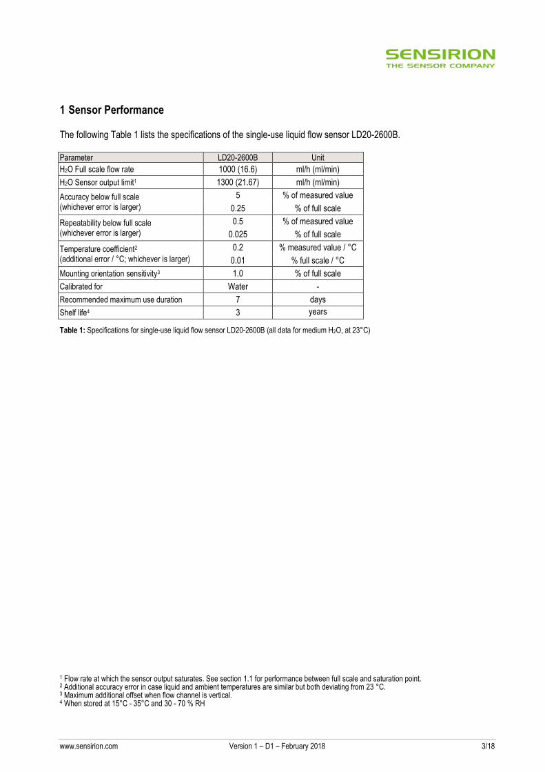
The following Table 1 lists the specifications of the single-use liquid flow sensor LD20-2600B. Parameter LD20-2600B Unit
H2O Full scale flow rate 1000 (16.6) ml/h (ml/min)
H2O Sensor output limit1 1300 (21.67) ml/h (ml/min)
Accuracy below full scale (whichever error is larger)
5 % of measured value
0.25 % of full scale
Repeatability below full scale (whichever error is larger)
0.5 % of measured value
0.025 % of full scale
Temperature coefficient2 (additional error / °C; whichever is larger)
0.2 % measured value / °C
0.01 % full scale / °C
Mounting orientation sensitivity3 1.0 % of full scale
Calibrated for Water -
Recommended maximum use duration 7 days
Shelf life4 3 years
Table 1: Specifications for single-use liquid flow sensor LD20-2600B (all data for medium H2O, at 23°C)
1 Flow rate at which the sensor output saturates. See section 1.1 for performance between full scale and saturation point. 2 Additional accuracy error in case liquid and ambient temperatures are similar but both deviating from 23 °C. 3 Maximum additional offset when flow channel is vertical. 4 When stored at 15°C - 35°C and 30 - 70 % RH
www.sensirion.com Version 1 – D1 – February 2018 4/18
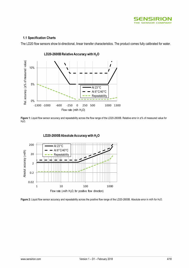
1.1 Specification Charts
The LD20 flow sensors show bi-directional, linear transfer characteristics. The product comes fully calibrated for water.
Figure 1: Liquid flow sensor accuracy and repeatability across the flow range of the LD20-2600B. Relative error in ±% of measured value for H2O.
Figure 2: Liquid flow sensor accuracy and repeatability across the positive flow range of the LD20-2600B. Absolute error in ml/h for H2O.
-1300 -1000 -600 -250 0 250 500 1000 1300
0%
5%
10%
Rel
. acc
urac
y (±
% o
f mea
sure
d va
lue)
Flow rate (ml/h H2O)
LD20-2600B Relative Accuracy with H2O
At 23°C
At 6°C/40°C
Repeatability
0.02
0.2
2
20
200
1 10 100 1000
Abs
olut
acc
urac
y (m
l/h)
Flow rate (ml/h H2O, for positive flow direction)
LD20-2600B Absolute Accuracy with H2O
At 23°C
At 6°C/40°C
Repeatability
www.sensirion.com Version 1 – D1 – February 2018 5/18
2 Specifications
2.1 Electrical Specifications
Parameter Symbol Conditions Min. Typical Max. Units Comments
Supply voltage DC VDD
3.2 3.5 3.8 V
Power-up/down level VPOR 2.3 2.5 2.7 V
Supply current IDD
Measurement 4.5 6.0 mA VDD = 3.5 V
Idle mode 0.6 mA
Sleep mode 0.001 mA
Table 2: DC characteristics
2.2 Timing Specifications
Parameter Symbol Min. Typical Max. Units Comments
Power-up time tPU
25 ms Time to sensor ready
Soft reset time tSR 25 ms Time between soft reset command or exit sleep mode and sensor ready
Warm-up time tw 120 ms Time needed until sensor output is within specification according to section 1.1 at 50% full scale flow rate.
I2C SCL frequency fI2C 400 1000 kHz
Update rate liquid flow value and signaling flags
1800 2000 2200 Hz
Update rate temperature value
73 83 111 Hz
Table 3: Timing specifications
2.3 Absolute Minimum and Maximum Ratings
Parameter Rating Unit
Operating temperature +5 … +45 (+41 … +113) °C (°F)
Operating humidity 0…95 %, non-condensing % RH
Short term storage temperature5 -40 … +60 (-40 … +140) °C (°F)
Short term storage humidity5 0…95 %, non-condensing % RH
ESD HBM (human body model) 6 2 kV
Maximum supply voltage 5.5 V
Table 4: Absolute minimum and maximum ratings
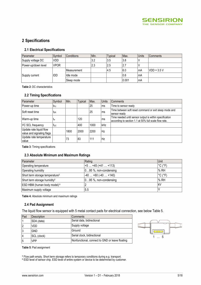
2.4 Pad Assignment
The liquid flow sensor is equipped with 5 metal contact pads for electrical connection, see below Table 5.
Pad Description Comments
1 SDA (data) Serial data, bidirectional
2 VDD Supply voltage
3 GND Ground
4 SCL (clock) Serial clock, bidirectional
5 VPP Nonfunctional, connect to GND or leave floating
Table 5: Pad assignment
5 Flow path empty. Short term storage refers to temporary conditions during e.g. transport. 6 ESD level of sensor chip. ESD level of entire system or device to be determined by customer.
1 … 5
www.sensirion.com Version 1 – D1 – February 2018 6/18
3 Sensor Output Signal Description
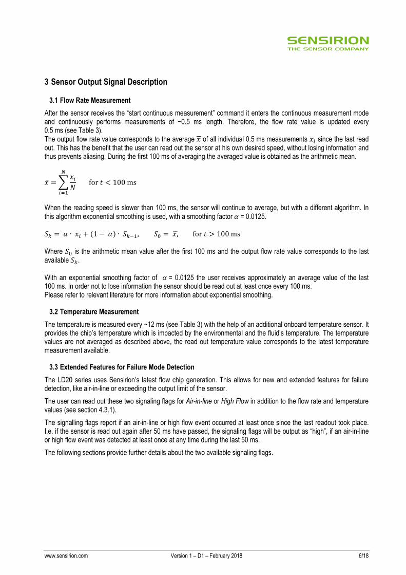
3.1 Flow Rate Measurement
After the sensor receives the “start continuous measurement” command it enters the continuous measurement mode and continuously performs measurements of ~0.5 ms length. Therefore, the flow rate value is updated every 0.5 ms (see Table 3). The output flow rate value corresponds to the average 𝑥 of all individual 0.5 ms measurements 𝑥𝑖 since the last read out. This has the benefit that the user can read out the sensor at his own desired speed, without losing information and thus prevents aliasing. During the first 100 ms of averaging the averaged value is obtained as the arithmetic mean.
�̅� = ∑𝑥𝑖
𝑁
𝑁
𝑖=1
for 𝑡 < 100 ms
When the reading speed is slower than 100 ms, the sensor will continue to average, but with a different algorithm. In
this algorithm exponential smoothing is used, with a smoothing factor 𝛼 = 0.0125. 𝑆𝑘 = 𝛼 ∙ 𝑥𝑖 + (1 − 𝛼) ∙ 𝑆𝑘−1, 𝑆0 = 𝑥,̅ for 𝑡 > 100 ms Where 𝑆0 is the arithmetic mean value after the first 100 ms and the output flow rate value corresponds to the last available 𝑆𝑘. With an exponential smoothing factor of 𝛼 = 0.0125 the user receives approximately an average value of the last 100 ms. In order not to lose information the sensor should be read out at least once every 100 ms. Please refer to relevant literature for more information about exponential smoothing.
3.2 Temperature Measurement
The temperature is measured every ~12 ms (see Table 3) with the help of an additional onboard temperature sensor. It provides the chip’s temperature which is impacted by the environmental and the fluid’s temperature. The temperature values are not averaged as described above, the read out temperature value corresponds to the latest temperature measurement available.
3.3 Extended Features for Failure Mode Detection
The LD20 series uses Sensirion’s latest flow chip generation. This allows for new and extended features for failure detection, like air-in-line or exceeding the output limit of the sensor.
The user can read out these two signaling flags for Air-in-line or High Flow in addition to the flow rate and temperature values (see section 4.3.1).
The signalling flags report if an air-in-line or high flow event occurred at least once since the last readout took place. I.e. if the sensor is read out again after 50 ms have passed, the signaling flags will be output as “high”, if an air-in-line or high flow event was detected at least once at any time during the last 50 ms.
The following sections provide further details about the two available signaling flags.
www.sensirion.com Version 1 – D1 – February 2018 7/18
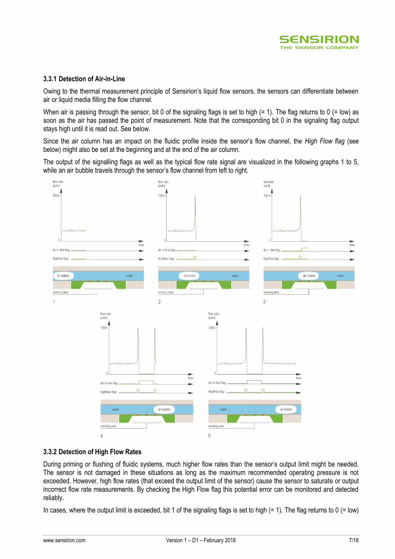
3.3.1 Detection of Air-in-Line
Owing to the thermal measurement principle of Sensirion’s liquid flow sensors, the sensors can differentiate between air or liquid media filling the flow channel.
When air is passing through the sensor, bit 0 of the signaling flags is set to high (= 1). The flag returns to 0 (= low) as soon as the air has passed the point of measurement. Note that the corresponding bit 0 in the signaling flag output stays high until it is read out. See below.
Since the air column has an impact on the fluidic profile inside the sensor’s flow channel, the High Flow flag (see below) might also be set at the beginning and at the end of the air column.
The output of the signalling flags as well as the typical flow rate signal are visualized in the following graphs 1 to 5, while an air bubble travels through the sensor’s flow channel from left to right.
3.3.2 Detection of High Flow Rates
During priming or flushing of fluidic systems, much higher flow rates than the sensor’s output limit might be needed. The sensor is not damaged in these situations as long as the maximum recommended operating pressure is not exceeded. However, high flow rates (that exceed the output limit of the sensor) cause the sensor to saturate or output incorrect flow rate measurements. By checking the High Flow flag this potential error can be monitored and detected reliably.
In cases, where the output limit is exceeded, bit 1 of the signaling flags is set to high (= 1). The flag returns to 0 (= low)
www.sensirion.com Version 1 – D1 – February 2018 8/18
as soon as the flow rate falls below the output limit. Note that the corresponding bit 0 in the signaling flag output stays high until it is read out.
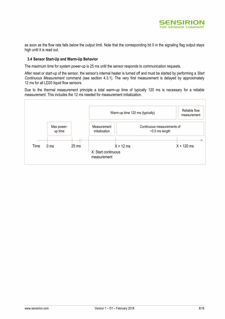
3.4 Sensor Start-Up and Warm-Up Behavior
The maximum time for system power-up is 25 ms until the sensor responds to communication requests.
After reset or start-up of the sensor, the sensor’s internal heater is turned off and must be started by performing a Start Continuous Measurement command (see section 4.3.1). The very first measurement is delayed by approximately 12 ms for all LD20 liquid flow sensors.
Due to the thermal measurement principle a total warm-up time of typically 120 ms is necessary for a reliable measurement. This includes the 12 ms needed for measurement initialization.
Time 0 ms 25 ms
X: Start continuous
measurement
X + 12 ms X + 120 ms
Max power-
up time
Warm-up time 120 ms (typically) Reliable flow measurement
Continuous measurements of
~0.5 ms length
Measurement
initialization
//
www.sensirion.com Version 1 – D1 – February 2018 9/18
4 Digital Interface Description
The sensor’s digital interface is compatible with the I2C protocol. This chapter describes the available command set. For detailed information about the I2C protocol, please consult the document "NXP I2C-bus specification and user manual" (http://www.nxp.com/documents/user_manual/UM10204.pdf). The physical interface consists of two bus lines, a data line (SDA) and a clock line (SCL) which need to be connected via pull-up resistors to the bus voltage of the system.
4.1 I2C Address
The sensor’s I2C address is 8. The I2C header is formed by the I2C address followed by a read or write bit.
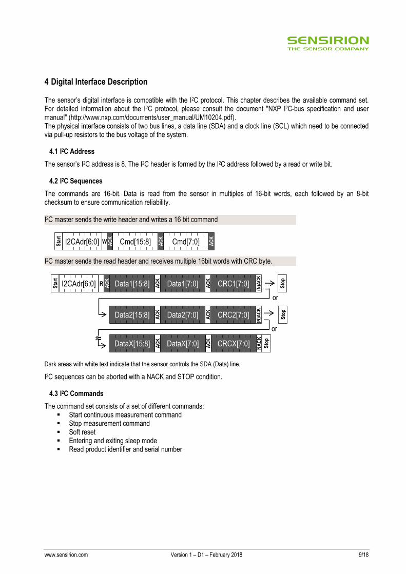
4.2 I2C Sequences
The commands are 16-bit. Data is read from the sensor in multiples of 16-bit words, each followed by an 8-bit checksum to ensure communication reliability. I2C master sends the write header and writes a 16 bit command
I2C master sends the read header and receives multiple 16bit words with CRC byte.
Dark areas with white text indicate that the sensor controls the SDA (Data) line.
I2C sequences can be aborted with a NACK and STOP condition.
4.3 I2C Commands
The command set consists of a set of different commands: Start continuous measurement command Stop measurement command Soft reset Entering and exiting sleep mode Read product identifier and serial number
Sta
rt
W AC
K
I2CAdr[6:0] Cmd[15:8] AC
K
Cmd[7:0] AC
K
Sta
rt
R AC
K
I2CAdr[6:0] Data1[15:8] AC
K
Data1[7:0] AC
K
CRC1[7:0]
(N)A
CK
Sto
p
Data2[15:8] AC
K
Data2[7:0] AC
K
CRC2[7:0]
(N)A
CK
Sto
p
or
DataX[15:8] AC
K
DataX[7:0] AC
K
CRCX[7:0]
NA
CK
S
top
or
≈
www.sensirion.com Version 1 – D1 – February 2018 10/18
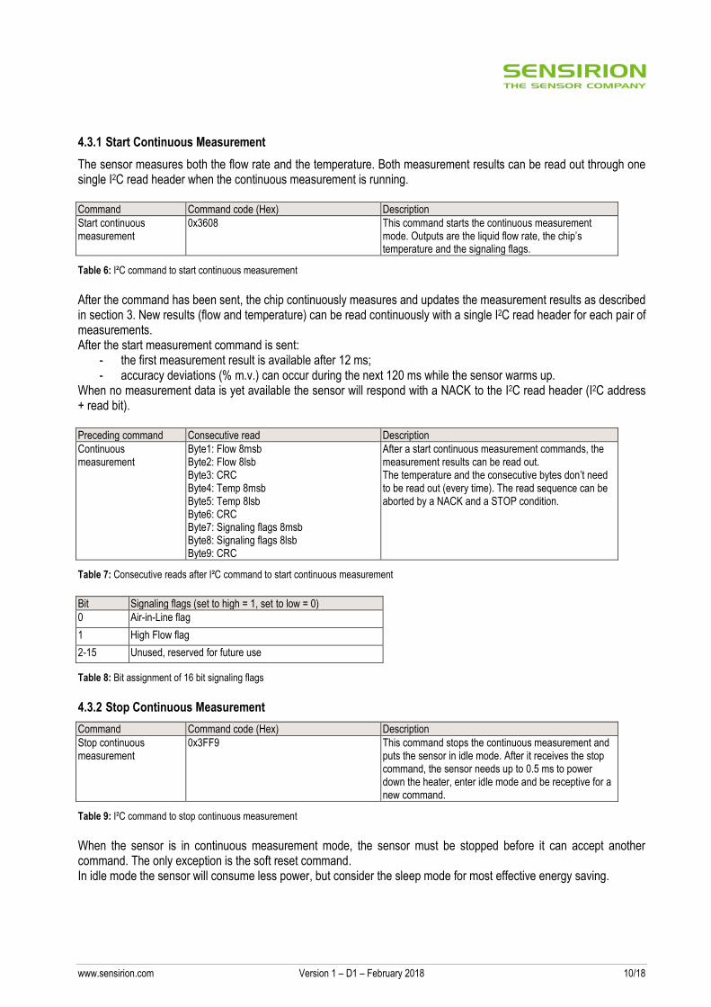
4.3.1 Start Continuous Measurement
The sensor measures both the flow rate and the temperature. Both measurement results can be read out through one single I2C read header when the continuous measurement is running. Command Command code (Hex) Description
Start continuous measurement
0x3608 This command starts the continuous measurement mode. Outputs are the liquid flow rate, the chip’s temperature and the signaling flags.
Table 6: I²C command to start continuous measurement
After the command has been sent, the chip continuously measures and updates the measurement results as described in section 3. New results (flow and temperature) can be read continuously with a single I2C read header for each pair of measurements. After the start measurement command is sent:
- the first measurement result is available after 12 ms; - accuracy deviations (% m.v.) can occur during the next 120 ms while the sensor warms up.
When no measurement data is yet available the sensor will respond with a NACK to the I2C read header (I2C address + read bit). Preceding command Consecutive read Description
Continuous measurement
Byte1: Flow 8msb Byte2: Flow 8lsb Byte3: CRC Byte4: Temp 8msb Byte5: Temp 8lsb Byte6: CRC Byte7: Signaling flags 8msb Byte8: Signaling flags 8lsb Byte9: CRC
After a start continuous measurement commands, the measurement results can be read out. The temperature and the consecutive bytes don’t need to be read out (every time). The read sequence can be aborted by a NACK and a STOP condition.
Table 7: Consecutive reads after I²C command to start continuous measurement
Bit Signaling flags (set to high = 1, set to low = 0)
0 Air-in-Line flag
1 High Flow flag
2-15 Unused, reserved for future use
Table 8: Bit assignment of 16 bit signaling flags
4.3.2 Stop Continuous Measurement
Command Command code (Hex) Description
Stop continuous measurement
0x3FF9 This command stops the continuous measurement and puts the sensor in idle mode. After it receives the stop command, the sensor needs up to 0.5 ms to power down the heater, enter idle mode and be receptive for a new command.
Table 9: I²C command to stop continuous measurement
When the sensor is in continuous measurement mode, the sensor must be stopped before it can accept another command. The only exception is the soft reset command. In idle mode the sensor will consume less power, but consider the sleep mode for most effective energy saving.
www.sensirion.com Version 1 – D1 – February 2018 11/18
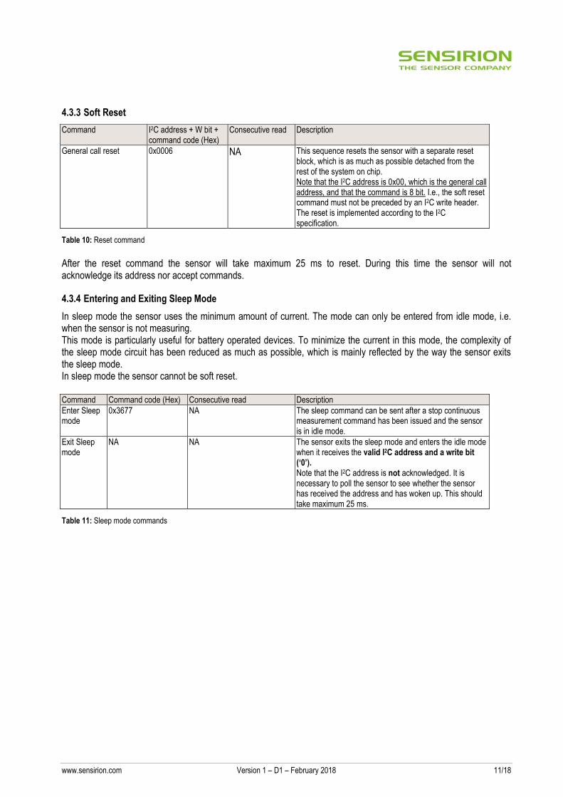
4.3.3 Soft Reset
Table 10: Reset command
After the reset command the sensor will take maximum 25 ms to reset. During this time the sensor will not acknowledge its address nor accept commands.
4.3.4 Entering and Exiting Sleep Mode
In sleep mode the sensor uses the minimum amount of current. The mode can only be entered from idle mode, i.e. when the sensor is not measuring. This mode is particularly useful for battery operated devices. To minimize the current in this mode, the complexity of the sleep mode circuit has been reduced as much as possible, which is mainly reflected by the way the sensor exits the sleep mode. In sleep mode the sensor cannot be soft reset.
Table 11: Sleep mode commands
Command I2C address + W bit + command code (Hex)
Consecutive read Description
General call reset 0x0006 NA This sequence resets the sensor with a separate reset block, which is as much as possible detached from the rest of the system on chip. Note that the I2C address is 0x00, which is the general call address, and that the command is 8 bit. I.e., the soft reset command must not be preceded by an I2C write header. The reset is implemented according to the I2C specification.
Command Command code (Hex) Consecutive read Description
Enter Sleep mode
0x3677 NA The sleep command can be sent after a stop continuous measurement command has been issued and the sensor is in idle mode.
Exit Sleep mode
NA NA The sensor exits the sleep mode and enters the idle mode when it receives the valid I2C address and a write bit (‘0’). Note that the I2C address is not acknowledged. It is necessary to poll the sensor to see whether the sensor has received the address and has woken up. This should take maximum 25 ms.
www.sensirion.com Version 1 – D1 – February 2018 12/18
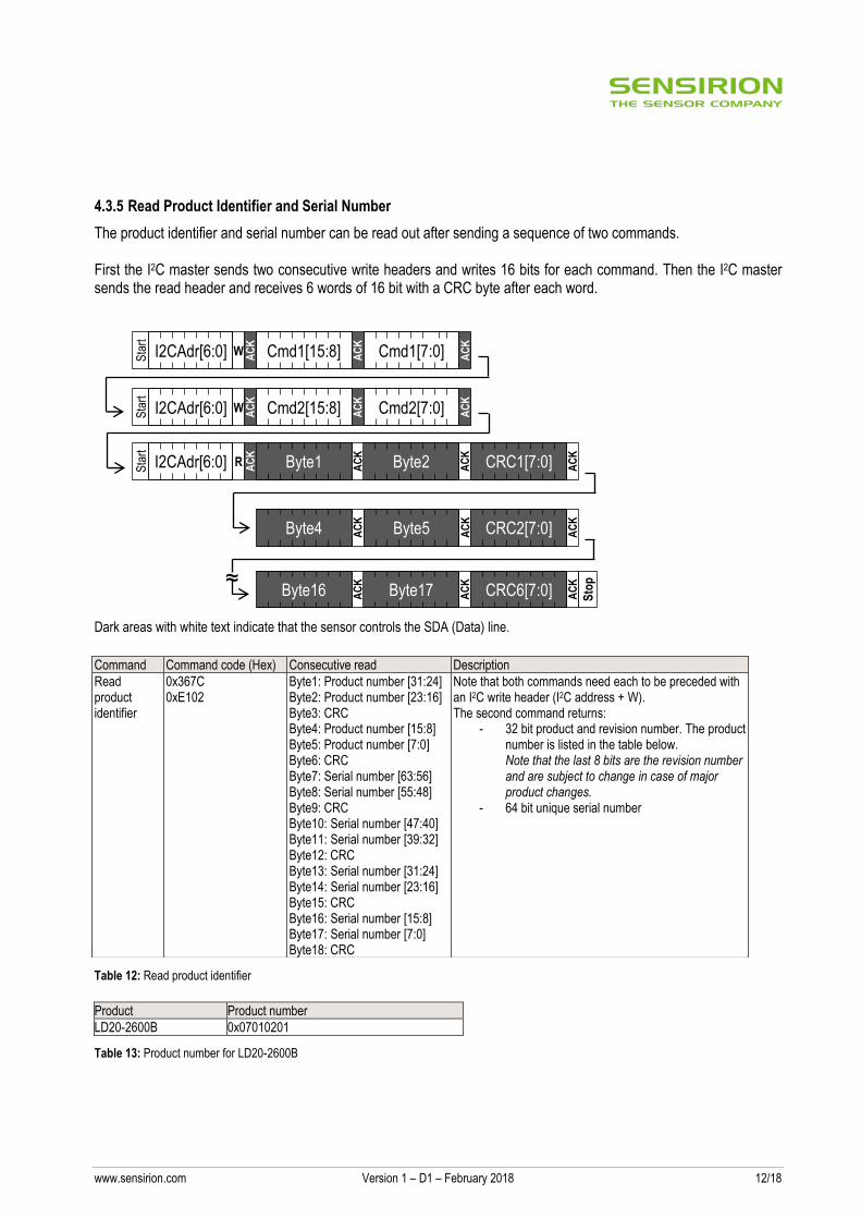
4.3.5 Read Product Identifier and Serial Number
The product identifier and serial number can be read out after sending a sequence of two commands. First the I2C master sends two consecutive write headers and writes 16 bits for each command. Then the I2C master sends the read header and receives 6 words of 16 bit with a CRC byte after each word.
Dark areas with white text indicate that the sensor controls the SDA (Data) line.
Table 12: Read product identifier
Product Product number
LD20-2600B 0x07010201
Table 13: Product number for LD20-2600B
Command Command code (Hex) Consecutive read Description
Read product identifier
0x367C 0xE102
Byte1: Product number [31:24] Byte2: Product number [23:16] Byte3: CRC Byte4: Product number [15:8] Byte5: Product number [7:0] Byte6: CRC Byte7: Serial number [63:56] Byte8: Serial number [55:48] Byte9: CRC Byte10: Serial number [47:40] Byte11: Serial number [39:32] Byte12: CRC Byte13: Serial number [31:24] Byte14: Serial number [23:16] Byte15: CRC Byte16: Serial number [15:8] Byte17: Serial number [7:0] Byte18: CRC
Note that both commands need each to be preceded with an I2C write header (I2C address + W). The second command returns:
- 32 bit product and revision number. The product number is listed in the table below. Note that the last 8 bits are the revision number and are subject to change in case of major product changes.
- 64 bit unique serial number
Sta
rt
W AC
K
I2CAdr[6:0] Cmd1[15:8] AC
K
Cmd1[7:0] AC
K
Sta
rt
W AC
K
I2CAdr[6:0] Cmd2[15:8] AC
K
Cmd2[7:0] AC
K
Byte4 AC
K
Byte5 AC
K
Sta
rt
R AC
K
I2CAdr[6:0] Byte1 AC
K
Byte2 AC
K
CRC1[7:0] AC
K
CRC2[7:0] AC
K
Byte16 AC
K
Byte17 AC
K
CRC6[7:0] AC
K
Sto
p ≈
www.sensirion.com Version 1 – D1 – February 2018 13/18
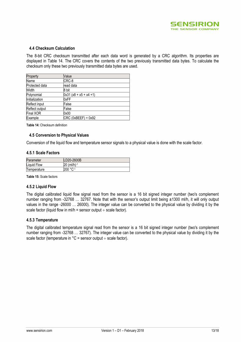
4.4 Checksum Calculation
The 8-bit CRC checksum transmitted after each data word is generated by a CRC algorithm. Its properties are displayed in Table 14. The CRC covers the contents of the two previously transmitted data bytes. To calculate the checksum only these two previously transmitted data bytes are used. Property Value
Name CRC-8
Protected data read data
Width 8 bit
Polynomial 0x31 (x8 + x5 + x4 +1)
Initialization 0xFF
Reflect input False
Reflect output False
Final XOR 0x00
Example CRC (0xBEEF) = 0x92
Table 14: Checksum definition
4.5 Conversion to Physical Values
Conversion of the liquid flow and temperature sensor signals to a physical value is done with the scale factor.
4.5.1 Scale Factors
Parameter LD20-2600B
Liquid Flow 20 (ml/h)-1
Temperature 200 °C-1
Table 15: Scale factors
4.5.2 Liquid Flow
The digital calibrated liquid flow signal read from the sensor is a 16 bit signed integer number (two's complement number ranging from -32768 … 32767. Note that with the sensor’s output limit being ±1300 ml/h, it will only output values in the range -26000 … 26000). The integer value can be converted to the physical value by dividing it by the
scale factor (liquid flow in ml/h = sensor output scale factor).
4.5.3 Temperature
The digital calibrated temperature signal read from the sensor is a 16 bit signed integer number (two's complement number ranging from -32768 … 32767). The integer value can be converted to the physical value by dividing it by the
scale factor (temperature in °C = sensor output scale factor).
www.sensirion.com Version 1 – D1 – February 2018 14/18
5 Fluidic Specifications and Connections
Parameter LD20-2600B
Wetted materials
Polyetherimide (PEI), Liquid-Crystal-Polymer (LCP), medical-grade adhesive
Fluidic connector ports (fittings) Barbed fittings
Recommended tubing ID for barbed fittings7 3.2 mm (1/8”)
Pressure drop (at full scale flow rate, H2O, 23 °C) < 0.2 mbar
Table 16: Fluidic specifications and connections
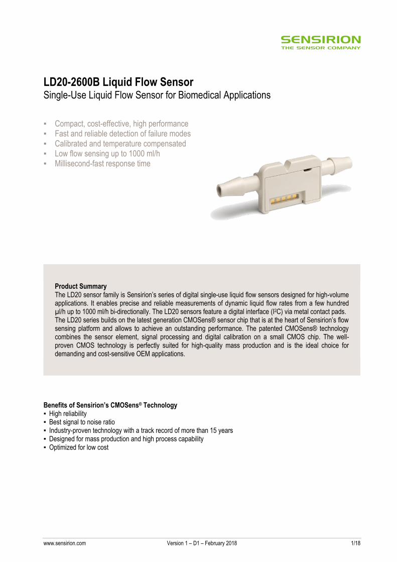
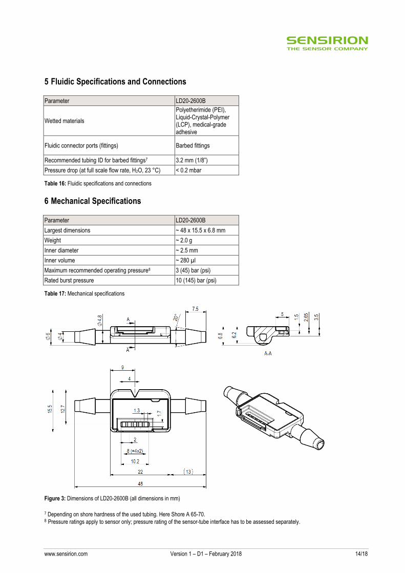
6 Mechanical Specifications
Parameter LD20-2600B
Largest dimensions ~ 48 x 15.5 x 6.8 mm
Weight ~ 2.0 g
Inner diameter ~ 2.5 mm
Inner volume ~ 280 µl
Maximum recommended operating pressure8 3 (45) bar (psi)
Rated burst pressure 10 (145) bar (psi)
Table 17: Mechanical specifications
Figure 3: Dimensions of LD20-2600B (all dimensions in mm)
7 Depending on shore hardness of the used tubing. Here Shore A 65-70. 8 Pressure ratings apply to sensor only; pressure rating of the sensor-tube interface has to be assessed separately.
www.sensirion.com Version 1 – D1 – February 2018 15/18
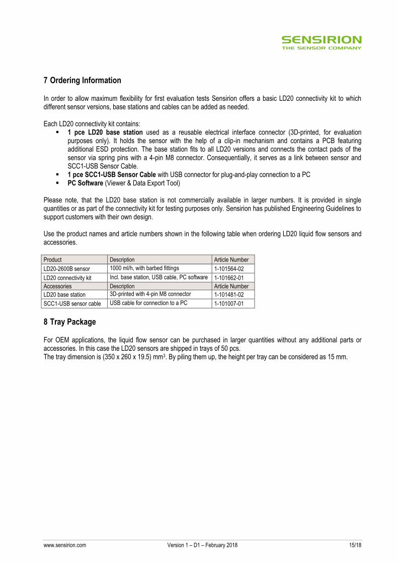
7 Ordering Information
In order to allow maximum flexibility for first evaluation tests Sensirion offers a basic LD20 connectivity kit to which different sensor versions, base stations and cables can be added as needed. Each LD20 connectivity kit contains:
1 pce LD20 base station used as a reusable electrical interface connector (3D-printed, for evaluation purposes only). It holds the sensor with the help of a clip-in mechanism and contains a PCB featuring additional ESD protection. The base station fits to all LD20 versions and connects the contact pads of the sensor via spring pins with a 4-pin M8 connector. Consequentially, it serves as a link between sensor and SCC1-USB Sensor Cable.
1 pce SCC1-USB Sensor Cable with USB connector for plug-and-play connection to a PC PC Software (Viewer & Data Export Tool)
Please note, that the LD20 base station is not commercially available in larger numbers. It is provided in single quantities or as part of the connectivity kit for testing purposes only. Sensirion has published Engineering Guidelines to support customers with their own design. Use the product names and article numbers shown in the following table when ordering LD20 liquid flow sensors and accessories. Product Description Article Number
LD20-2600B sensor 1000 ml/h, with barbed fittings 1-101564-02
LD20 connectivity kit Incl. base station, USB cable, PC software 1-101662-01
Accessories Description Article Number
LD20 base station 3D-printed with 4-pin M8 connector 1-101481-02
SCC1-USB sensor cable USB cable for connection to a PC 1-101007-01
8 Tray Package
For OEM applications, the liquid flow sensor can be purchased in larger quantities without any additional parts or accessories. In this case the LD20 sensors are shipped in trays of 50 pcs. The tray dimension is (350 x 260 x 19.5) mm3. By piling them up, the height per tray can be considered as 15 mm.
www.sensirion.com Version 1 – D1 – February 2018 16/18
9 Important Notices
9.1 Warning, Personal Injury
Do not use this product as safety or emergency stop devices or in any other application where failure of the product could result in personal injury. Do not use this product for applications other than its intended and authorized use. Before installing, handling, using or servicing this product, please consult the data sheet and application notes. Failure to comply with these instructions could result in death or serious injury. If the Buyer shall purchase or use SENSIRION products for any unintended or unauthorized application, Buyer shall defend, indemnify and hold harmless SENSIRION and its officers, employees, subsidiaries, affiliates and distributors against all claims, costs, damages and expenses, and reasonable attorney fees arising out of, directly or indirectly, any claim of personal injury or death associated with such unintended or unauthorized use, even if SENSIRION shall be allegedly negligent with respect to the design or the manufacture of the product.
9.2 ESD Precautions
The inherent design of this component causes it to be sensitive to electrostatic discharge (ESD). To prevent ESD-induced damage and/or degradation, take customary and statutory ESD precautions when handling this product.
9.3 Warranty
SENSIRION warrants solely to the original purchaser of this product for a period of 12 months (one year) from the date of delivery that this product shall be of the quality, material and workmanship defined in SENSIRION’s published specifications of the product. Within such period, if proven to be defective, SENSIRION shall repair and/or replace this product, in SENSIRION’s discretion, free of charge to the Buyer, provided that: ▪ notice in writing describing the defects shall be given to SENSIRION within fourteen (14) days after their appearance; ▪ such defects shall be found, to SENSIRION’s reasonable satisfaction, to have arisen from SENSIRION’s faulty design, material, or
workmanship; ▪ the defective product shall be returned to SENSIRION’s factory at the Buyer’s expense; and ▪ the warranty period for any repaired or replaced product shall be limited to the unexpired portion of the original period. This warranty does not apply to any equipment which has not been installed and used within the specifications recommended by SENSIRION for the intended and proper use of the equipment. EXCEPT FOR THE WARRANTIES EXPRESSLY SET FORTH HEREIN, SENSIRION MAKES NO WARRANTIES, EITHER EXPRESS OR IMPLIED, WITH RESPECT TO THE PRODUCT. ANY AND ALL WARRANTIES, INCLUDING WITHOUT LIMITATION, WARRANTIES OF MERCHANTABILITY OR FITNESS FOR A PARTICULAR PURPOSE, ARE EXPRESSLY EXCLUDED AND DECLINED. SENSIRION is only liable for defects of this product arising under the conditions of operation provided for in the data sheet and proper use of the goods. SENSIRION explicitly disclaims all warranties, express or implied, for any period during which the goods are operated or stored not in accordance with the technical specifications. SENSIRION does not assume any liability arising out of any application or use of any product or circuit and specifically disclaims any and all liability, including without limitation consequential or incidental damages. All operating parameters, including without limitation recommended parameters, must be validated for each customer’s applications by customer’s technical experts. Recommended parameters can and do vary in different applications. SENSIRION reserves the right, without further notice, (i) to change the product specifications and/or the information in this document and (ii) to improve reliability, functions and design of this product. Copyright© 2017, by SENSIRION. CMOSens® is a trademark of Sensirion All rights reserved

www.sensirion.com Version 1 – D1 – February 2018 17/18
10 Headquarters and Subsidiaries
Sensirion AG Laubisruetistr. 50 CH-8712 Staefa ZH Switzerland phone: +41 44 306 40 00 fax: +41 44 306 40 30 [email protected] www.sensirion.com
Sensirion Inc., USA phone: +1 312 690 5858 [email protected] www.sensirion.com
Sensirion Korea Co. Ltd. phone: +82 31 337 7700~3 [email protected] www.sensirion.co.kr
Sensirion Japan Co. Ltd. phone: +81 3 3444 4940 [email protected] www.sensirion.co.jp
Sensirion China Co. Ltd. phone: +86 755 8252 1501 [email protected] www.sensirion.com.cn
Sensirion Taiwan Co. Ltd phone: +886 3 5506701 [email protected] www.sensirion.com To find your local representative, please visit www.sensirion.com/distributors
www.sensirion.com Version 1 – D1 – February 2018 18/18
Revision History of the LD20-2600B Datasheet
Revision Date Changes Chapter Description
1 Feb 2018 all First released version