LD145/WD145 SERIES ASSEMBLED IN USA BUTTERFLY … Butterfly V… · LD145/WD145 SERIES ASSEMBLED IN...
10
LD145/WD145 SERIES ASSEMBLED IN USA BUTTERFLY VALVE INSTALLATION OPERATION MAINTENANCE Document No: ES-1526 Revision Level: A Issued by: Charles Purser Date: 08/09/12 Revised by: Date: Approved by: Kevin Bartell Date: 08/09/12
Transcript of LD145/WD145 SERIES ASSEMBLED IN USA BUTTERFLY … Butterfly V… · LD145/WD145 SERIES ASSEMBLED IN...
LD145/WD145 SERIES
ASSEMBLED IN USA BUTTERFLY VALVE
INSTALLATION
OPERATION MAINTENANCE
Document No: ES-1526 Revision Level: A Issued by: Charles Purser Date: 08/09/12
Revised by: Date: Approved by: Kevin Bartell Date: 08/09/12

APOLLO® BFV INSTALLATION MANUAL - Page 2 of 10
ES1526,Rev A, LD-WD145 Butterfly Valve IOM.doc P.O. Box 125 /1418 S. Pearl Street, Pageland, SC 29728
INTRODUCTION ..................................................................... 3 DESIGN FEATURES .............................................................................................. 3 OPERATING PRESSURES ...................................................................................... 3 PRODUCT STORAGE ............................................................................................. 3 PRODUCT MARKING ............................................................................................. 4 FIGURE 1: APOLLO® BUTTERFLY VALVE INDENTIFICATION TAG ......................... 4
INSTALLATION INFORMATION ............................................... 4 INSTALLATION INSTRUCTIONS ............................................................................. 4 FIGURE 2: VALVE IN PARTIALLY OPEN POSITION ................................................ 5 FIGURE 3: VALVE IN FULL OPEN POSITION ......................................................... 5 MAINTENANCE AND REPAIR…………………………………………………………………….6 DISC CHORD DIMENSIONS .................................................................................. 6 TABLE 1: BUTTERFLY VALVE DISC CHORD DIMENSIONS…………………………..….6 FIGURE 4: DISC CHORD………..………………………………………………………………..6 TABLE 2: STUD AND BOLT SPECIFICATION FOR LUG AND WAFER ..................... 7 FIGURE 5: FLANGE BOLT TIGHTENING SEQUENCE ............................................ 7
ASSEMBLY/DISASSEMBLY INSTRUCTIONS .......................... 8 LD145/WD145 SERIES BUTTERFLY VALVE ASSEMBLY & DISASSEMBLY ........... 8 LD145/WD145 SERIES PARTS LIST & EXPLODED VIEW ..................................... 8 TABLE 3: LD145/WD145 SERIES SEAT MATERIAL TEMPERATURE RANGES ...... 8
MANUAL OPERATOR INSTALLATION ..................................... 9 LEVER HANDLE MOUNTING PROCEDURE ........................................................... 9 FIGURE 6: NOTCHPLATE INSTALLATION POSITION………………………………………9 MANUAL GEAR OPERATOR MOUNTING PROCEDURE ........................................ 10 FIGURE 7: GEAR OPERATOR INSTALLATION POSITION ..................................... 10
AMENDMENT REGISTER ..................................................... 10

APOLLO® BFV INSTALLATION MANUAL - Page 3 of 10
ES1526,Rev A, LD-WD145 Butterfly Valve IOM.doc P.O. Box 125 /1418 S. Pearl Street, Pageland, SC 29728
INTRODUCTION DESIGN FEATURES LD145/WD145 SERIES • Assembled in the USA. • Available in wafer or lug body. • Flange holes comply with ANSI Class 125/150 dimensions. • Cast-in top plate with ISO-5211 mounting dimensions provides for direct-mounting of
Apollo® actuators and manual operators. • The face-to-face dimensions were designed to comply with MSS SP-67 and API 609. • Wafer body features alignment holes for ease of installation. • Through-shaft design with square shaft to disc connection without pins or bolts. Disc-
to-seat interface provides bubble-tight shut-off with reduced torque and extended service life.
• Equipped with a stretch-resistant, non-collapsible, blowout-proof, phenolic-backed cartridge seat. (14” through 24” have aluminum backing)
• Meets the intent and has passed AWWA C504-87 Section 5 proof of design tests (3”-24”).
• Factory tested to 110% of full rated pressure in both directions before shipping.
FLANGE AND PIPE COMPATIBILITY APOLLO® Butterfly Valves are designed to fit between the following piping flanges: • ANSI 125 Cast iron flanges (all sizes) • ANSI 150 Steel flanges, schedule 40 (all sizes) • ANSI 150 Steel flanges, schedule 80 (2”-12”) Note: When installing valves in schedule 80 piping, make sure the valve is properly
centered between the pipe flanges to prevent disc edge damage since the clearance between the disc O.D. and the pipe I.D. is reduced. If there is a compatibility question, compare the minimum pipe I.D. with the disc chord dimensions in Table 1 (reference Figure 4).
OPERATING PRESSURES LD145/WD145 SERIES: • 2”-12” (DN50-DN300) – 200 psig (13.8 bar) • 14”-24” (DN350-DN600) – 150 psig (10.3 bar) • All Sizes – Vacuum Rating – 29 inches of Hg (737mm of Hg)
PRODUCT STORAGE • The valves should be stored with the disc in the partially open position. • The valves should be stored indoors in a clean, dry, well-ventilated place away from
corrosive materials and protected from excessive dust and dirt. • The valves should be stored on a rack or pallet off the floor and arranged to prevent
damage during handling. • Keep valves out of direct sunlight and in a cool location to prolong elastomer life. • Valves should be protected to prevent damage to the flange faces, disc sealing edge and
operator.

APOLLO® BFV INSTALLATION MANUAL - Page 4 of 10
ES1526,Rev A, LD-WD145 Butterfly Valve IOM.doc P.O. Box 125 /1418 S. Pearl Street, Pageland, SC 29728
PRODUCT MARKING All APOLLO® Butterfly Valves are equipped with an identification tag attached to the valve neck (Figure 1). This tag provides the part number and the maximum pressure rating.
FIGURE 1: APOLLO® BUTTERFLY VALVE INDENTIFICATION TAG
INSTALLATION INFORMATION
APOLLO® butterfly valves are designed for use between the faces of ANSI 125 and 150 pound flat, raised face, slip-on or weld-neck flanges at the pressure indicated on the hang-tag. Flange gaskets should NOT be used. All APOLLO® resilient seated butterfly valves are bi-directional with the ability to shut-off tightly and control flow in either direction. All LD145 Series APOLLO® lug style butterfly valves may be used for dead-end service in either direction at their full pressure rating. INSTALLATION INSTRUCTIONS Step 1. Check to make sure that the pipe flange and valve sealing faces are clean and free
from any debris (pipe scale, welding slag, etc.). Step 2. Check the valve nameplate to ensure that the pressure is correct for the
application. Check the valve body to ensure that the valve materials are correct for the application. See Table 3 for seat material temperature ratings.
WARNING! – Apollo butterfly valves should never be installed where service conditions could exceed the valve ratings. Failure to heed warning may result in personal injury or property damage.
Step 3. The seat sealing face on the LD145/WD145 Series butterfly valves is wider than
the valve body providing a leak-proof seal when compressed between pipe flanges. Therefore, no flange gaskets are required when installing any APOLLO® butterfly valve.
Step 4. To prevent damage to the disc sealing edge during installation, position the disc in
the “partially open” position (Figure 2) so that the disc is still contained within the valve body.

APOLLO® BFV INSTALLATION MANUAL - Page 5 of 10
ES1526,Rev A, LD-WD145 Butterfly Valve IOM.doc P.O. Box 125 /1418 S. Pearl Street, Pageland, SC 29728
FIGURE 2: VALVE IN PARTIALLY OPEN POSITION
Step 5. Spread the pipe flanges apart allowing the valve to be slipped easily in between the
flanges. Step 6. Center the valve between the flanges and loosely install all the flange bolts. On the
Model 145 wafer valve, the flange bolts that pass through the alignment lugs should be installed first. Consult Table 2 for correct flange bolt size and quantity.
Step 7. Slowly open the valve to the full open position (Figure 3) and back to the partially open position ensuring that the disc moves freely without any obstruction. If no obstruction is encountered, return the valve to the full open position and hand-tighten all flange bolts.
FIGURE 3: VALVE IN FULL OPEN POSITION
Step 8. Rotate the disc from the fully open position to the fully closed position and make
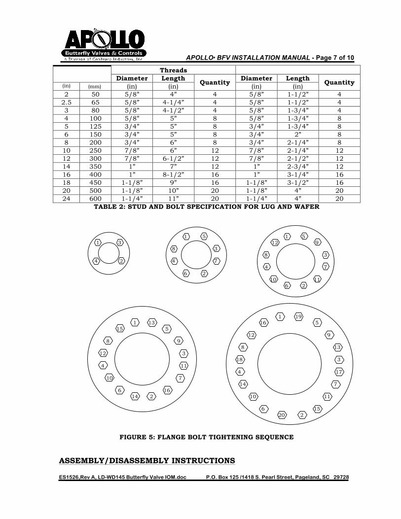
sure that the valve is properly centered and the disc edge does not contact the pipe ID. Return the disc to the full open position and tighten the flange bolts following the bolt tightening sequence shown in Figure 5. However, do not fully tighten each flange bolt all at once. Tighten each bolt incrementally following the sequence in Figure 5 several times until the flange bolts are tight. After all flange bolts are fully tightened, cycle the valve from full open to full closed to ensure that there is proper disc clearance.

APOLLO® BFV INSTALLATION MANUAL - Page 6 of 10
ES1526,Rev A, LD-WD145 Butterfly Valve IOM.doc P.O. Box 125 /1418 S. Pearl Street, Pageland, SC 29728
MAINTENANCE AND REPAIR APOLLO® butterfly valves are designed for extended service with minimal wear and servicing. No regular lubrication is required. Prior to any replacement or repair, the valve must be removed from the line following these precautions. SAFETY FIRST! For your safety, ask the following questions before working on a valve:
• WHAT IS IN THE LINE? WHAT IS IN THE VALVE? o Be sure you know what fluid is in the valve. IF there is ANY doubt, double
check with the proper supervisor. • ARE YOU PROTECTED?
o Wear proper protective clothing and equipment normally required to avoid injury from the specific fluid in the line.
• IS THE PIPE LINE DEPRESSURIZED? o Depressurize the line and drain the system fluid before you work on the
valve. • DISCONNECT AIR OR ELECTRICAL POWER TO AUTOMATED VALVES.
o If the valve is automated, disconnect all actuation power (air, electric, or hydraulic) to the valve.
• Ensure that the disc is in the partially open or full closed position before removing the valve from the line.
DISC CHORD DIMENSIONS TABLE 1: BUTTERFLY VALVE Figure 4: DISC CHORD DISC CHORD DIMENSIONS
Valve Size Wafer Body Lug Body
Heavy Hex Bolts & Nuts w/ NC Hex Head Screws w/ NC Threads
Valve Size Disc Chord (in) (mm) (in) 2 50 1.133
2.5 65 1.706 3 80 2.450 4 100 3.488 5 125 4.296 6 150 5.697 8 200 7.468 10 250 9.484 12 300 11.456 14 350 13.000 16 400 14.970 18 450 16.847 20 500 18.650 24 600 22.558
APOLLO® BFV INSTALLATION MANUAL - Page 7 of 10
ES1526,Rev A, LD-WD145 Butterfly Valve IOM.doc P.O. Box 125 /1418 S. Pearl Street, Pageland, SC 29728
Threads Diameter Length
Quantity Diameter Length
Quantity (in) (mm) (in) (in) (in) (in) 2 50 5/8” 4” 4 5/8” 1-1/2” 4
2.5 65 5/8” 4-1/4” 4 5/8” 1-1/2” 4 3 80 5/8” 4-1/2” 4 5/8” 1-3/4” 4 4 100 5/8” 5” 8 5/8” 1-3/4” 8 5 125 3/4” 5” 8 3/4” 1-3/4” 8 6 150 3/4” 5” 8 3/4” 2” 8 8 200 3/4” 6” 8 3/4” 2-1/4” 8 10 250 7/8” 6” 12 7/8” 2-1/4” 12 12 300 7/8” 6-1/2” 12 7/8” 2-1/2” 12 14 350 1” 7” 12 1” 2-3/4” 12 16 400 1” 8-1/2” 16 1” 3-1/4” 16 18 450 1-1/8” 9” 16 1-1/8” 3-1/2” 16 20 500 1-1/8” 10” 20 1-1/8” 4” 20 24 600 1-1/4” 11” 20 1-1/4” 4” 20
TABLE 2: STUD AND BOLT SPECIFICATION FOR LUG AND WAFER 1 5 1 5 1 3 12 9 8 3
8 3 4 2 4 7 4 7 6 2 10 11 6 2 1 19 1 13 16 5 15 5 12 9 8 9 8 13 12 3 18 3 4 11 4 17 10 7 14 7 6 16 14 2 10 11 6 15 20 2
FIGURE 5: FLANGE BOLT TIGHTENING SEQUENCE
ASSEMBLY/DISASSEMBLY INSTRUCTIONS

APOLLO® BFV INSTALLATION MANUAL - Page 8 of 10
ES1526,Rev A, LD-WD145 Butterfly Valve IOM.doc P.O. Box 125 /1418 S. Pearl Street, Pageland, SC 29728
LD145/WD145 SERIES BUTTERFLY VALVE ASSEMBLY AND DISASSEMBLY The LD145/WD145 Series butterfly valves have field replaceable parts (except bushings). Once the valve is removed from the line, inspect the parts for wear and contact your local APOLLO® distributor for replacement parts. LD145/WD145 Disassembly: SERIES PARTS LIST
1. Remove handle, gear operator, or actuator from mounting flange.
2. Remove the upper snap ring and washer from around the stem.
3. Remove the stem (by pulling it out of the body). 4. With the stem removed, the disc can easily be removed from
the seat (protect the sealing surfaces of the disc, if re-using). 5. The seat is pressed into the body and retained with set screws
located radially around the outside of the body. These must be removed first.
6. Press the seat out of the body using a rubber mallet or press. Assembly:
1. Place the new seat flush on the valve body. Carefully align the holes for the stem with the stem hole located in the body. A press should be used to insert the seat into the body. A large flat plate should be used in conjunction with the press to insert the seat and protect it from damage. Work slowly and guarantee that the seat remains parallel to the body as it is being pressed. Once inserted, check that the seat is centered in the body. At this point, a rubber mallet may be carefully used to adjust the position of the seat in the body.
2. Reinstall the set screws removed in step 5 of the disassembly. Tighten all set screws hand-tight (do not deform the liner of the seat with excessive screw torque). A thread sealing compound may be used on the set screws.
3. Reinstall the disc by working it into the seat at a 90° angle to the body. A rubber mallet may be used to align the shaft bore between the disc and body.
4. Align the flats on the bottom of the stem with the direction of the disc. The flats on the stem should align with the flats inside the disc. Drive the stem into the body until the snap ring on the stem is flush with the recess in the stem hole.
5. Re-install the washer and upper snap ring. Verify that the snap ring has fully engaged with the machined slot in the stem hole recess.
6. Actuate the valve to verify proper function.
Seat Type Min Max Nitrile (Buna-N) +10°F (-12°C) +180°F (82°C)
EPDM -30°F (-34°C) +275°F (135°C) FKM -15°F (-26°C) +400°F (204°C)
TABLE 3: LD145/WD145 SERIES SEAT MATERIAL TEMPERATURE RANGES MANUAL OPERATOR INSTALLATION
Item Qty Description1 1 Body2 1 Seat3 1 Shaft4 1 Disc5 1 Bushing6 1 Stem Seal7 1 O-ring8 2 Snap Ring
SCALE: DRN: CHKD: NO. REV.
NAME:
MAT'L:
EXP. NO.
CHANGE DESCRIPTION ECN NO. BY DATEREV.
APP'D:DATE:
NOTE: This drawing and the subject matter disclosed therein is the property of Conbraco Industries, Inc. and is not to becopied, used, appropriated or disclosed to others without the expressed written permission of Conbraco Industries, Inc.
R

APOLLO® BFV INSTALLATION MANUAL - Page 9 of 10
ES1526,Rev A, LD-WD145 Butterfly Valve IOM.doc P.O. Box 125 /1418 S. Pearl Street, Pageland, SC 29728
LEVER HANDLE MOUNTING PROCEDURE Step 1. First, start by loosely assembling the notch plate on the valve top plate. The
notchplate should be installed with the stop tabs pointing upward. The notchplate should be positioned so that the stop tabs coincide with the fully open and closed positions (reference Figure 6).
Step 2. Next, install the handle so that the lever mechanism fully engages in the notches
when the lever is released. Tighten the handle set screw. Step 3. Compress the handle lever and position the disc so that the valve is in the fully
closed position. Align the last notch on the notchplate with the closed position and the handle lever. Tighten the notch plate screws.
Step 4. Compress the handle lever and position the disc so that the valve is in the fully
open position and release the lever. The lever should line-up with the last notch on the notchplate (open position).
`
FIGURE 6: NOTCHPLATE INSTALLATION POSITION
MANUAL GEAR OPERATOR MOUNTING PROCEDURE Step 1. First, rotate the valve disc to the fully open position.

APOLLO® BFV INSTALLATION MANUAL - Page 10 of 10
ES1526,Rev A, LD-WD145 Butterfly Valve IOM.doc P.O. Box 125 /1418 S. Pearl Street, Pageland, SC 29728
Step 2. Next, slide the handwheel onto the end of the gear operator shaft. Line-up the hole in the handwheel with the hole in the gear operator shaft. Install the shear pin and rotate the gear operator to the open position.
Step 3. Next, line-up the valve stem with the gear operator bore and slide the gear operator
onto the valve with the handwheel pointing to the right of the valve when looking down the bore of the valve (Figure 7).
Step 4. Position the gear operator so that the tapped holes in the bottom of the gear
operator line-up with the valve top-plate mounting holes and install the mounting screws with lock washers.
Step 5. Loosen the gear operator travel stops and rotate the handwheel until the valve is in
the fully closed position. Tighten the gear operator stop on the right-hand side of the gear operator. (Note: There are two hex head set screws in tandem that represent the gear operator travel stops. Ensure that the first hex head screw is fully removed before loosening the travel stops.)
Step 6. Rotate the handwheel until the valve is in the fully open position. Tighten the gear
operator stop on the left-hand side of the gear operator. Step 7. Cycle the valve from the fully open position to the fully closed position to make
sure that the stops are set correctly.
SCALE: DRN: CHKD: NO. REV.
NAME:
MAT'L:
EXP. NO.
CHANGE DESCRIPTION ECN NO. BY DATEREV.
APP'D:DATE:
NOTE: This drawing and the subject matter disclosed therein is the property of Conbraco Industries, Inc. and is not to becopied, used, appropriated or disclosed to others without the expressed written permission of Conbraco Industries, Inc.
R
FIGURE 7: GEAR OPERATOR INSTALLATION POSITION
AMENDMENT REGISTER
Date Revision Section Description Initials 08/08/12 A All Released CRP


![Section 18 Butterfly Valves - AAP Industries · BUTTERFLY VALVES [18] Wafer Butterfly Valve with Gear-Op Stainless Steel Wafer Butterfly Valve Wafer Butterfly Valve with Stainless](https://static.fdocuments.net/doc/165x107/60a1925cd0b68c353a5fc104/section-18-butterfly-valves-aap-industries-butterfly-valves-18-wafer-butterfly.jpg)