LBI-38210B - EDACS 900 MHz GETC SHELF · the GETC (DIP switches and jumpers), balance the telephone...
26
LBI-38210B SERVICE SECTION FOR EDACS 900 MHz GETC SHELF TABLE OF CONTENTS Page INTRODUCTION . . . . . . . . . . . . . . . . . . . . . . . . . . . . . . . . . . . . . . . . . . . . 1 INSTALLATION . . . . . . . . . . . . . . . . . . . . . . . . . . . . . . . . . . . . . . . . . . . . 1 STATUS INDICATION . . . . . . . . . . . . . . . . . . . . . . . . . . . . . . . . . . . . . . . . . 1 ADJUSTMENTS . . . . . . . . . . . . . . . . . . . . . . . . . . . . . . . . . . . . . . . . . . . . 1 DIP SWITCHES . . . . . . . . . . . . . . . . . . . . . . . . . . . . . . . . . . . . . . . . 1 Selecting Channel Number . . . . . . . . . . . . . . . . . . . . . . . . . . . . . . . 1 Selecting RF Transmit Frequency . . . . . . . . . . . . . . . . . . . . . . . . . . . 1 Selecting Default Failsoft Operation . . . . . . . . . . . . . . . . . . . . . . . . . . 1 Selecting Trunking Mode Type . . . . . . . . . . . . . . . . . . . . . . . . . . . . 1 Selecting Test Mode . . . . . . . . . . . . . . . . . . . . . . . . . . . . . . . . . . 1 JUMPER CONFIGURATION . . . . . . . . . . . . . . . . . . . . . . . . . . . . . . . . . 1 SERVICE AND TEST . . . . . . . . . . . . . . . . . . . . . . . . . . . . . . . . . . . . . . . . . . 1 TERMINAL CONNECTION . . . . . . . . . . . . . . . . . . . . . . . . . . . . . . . . . 2 POWER SUPPLY TEST . . . . . . . . . . . . . . . . . . . . . . . . . . . . . . . . . . . . 3 MICROCOMPUTER CLOCK TEST . . . . . . . . . . . . . . . . . . . . . . . . . . . . . 3 OFF-SITE TEST . . . . . . . . . . . . . . . . . . . . . . . . . . . . . . . . . . . . . . . . 3 ON-SITE TEST . . . . . . . . . . . . . . . . . . . . . . . . . . . . . . . . . . . . . . . . 5 STATION TEST & ADJUSTMENT . . . . . . . . . . . . . . . . . . . . . . . . . . . . . . 5 TRUNKING TEST . . . . . . . . . . . . . . . . . . . . . . . . . . . . . . . . . . . . . . 6 APPENDIX A . . . . . . . . . . . . . . . . . . . . . . . . . . . . . . . . . . . . . . . . . A-0 APPENDIX B . . . . . . . . . . . . . . . . . . . . . . . . . . . . . . . . . . . . . . . . . B-0 LIST OF FIGURES & TABLES Figure 1 - Front Panel Status Indicators . . . . . . . . . . . . . . . . . . . . . . . . . . . . . . . . . 1 Figure 2 - GETC DIP Switch Definitions . . . . . . . . . . . . . . . . . . . . . . . . . . . . . . . . 2 Figure 3 - Terminal-To-GETC Connection Cable . . . . . . . . . . . . . . . . . . . . . . . . . . . . 3 Figure 4 - Station Test Setup . . . . . . . . . . . . . . . . . . . . . . . . . . . . . . . . . . . . . . . 7 Figure 5 - Typical 25 Hz Squarewave . . . . . . . . . . . . . . . . . . . . . . . . . . . . . . . . . . 7 Figure 6 - "EYE" Pattern . . . . . . . . . . . . . . . . . . . . . . . . . . . . . . . . . . . . . . . . 7 Table 1 - GETC Channel Number Setting . . . . . . . . . . . . . . . . . . . . . . . . . . . . . . . . 2 Table 2 - Jumper Setup andFunctions . . . . . . . . . . . . . . . . . . . . . . . . . . . . . . . . . . 2 Table 3 - GETC and RS-232C Pin Assignments . . . . . . . . . . . . . . . . . . . . . . . . . . . . 3 Table 4 - DIP Switch Test Configuration . . . . . . . . . . . . . . . . . . . . . . . . . . . . . . . . 6 ERICSSONZ Ericsson Inc. Private Radio Systems Mountain View Road Lynchburg, Virginia 24502 1-800-528-7711 (Outside USA, 804-528-7711) Printed in U.S.A.
Transcript of LBI-38210B - EDACS 900 MHz GETC SHELF · the GETC (DIP switches and jumpers), balance the telephone...

LBI-38210B
SERVICE SECTIONFOR
EDACS 900 MHz GETC SHELF
TABLE OF CONTENTS
Page
INTRODUCTION . . . . . . . . . . . . . . . . . . . . . . . . . . . . . . . . . . . . . . . . . . . . 1INSTALLATION . . . . . . . . . . . . . . . . . . . . . . . . . . . . . . . . . . . . . . . . . . . . 1STATUS INDICATION . . . . . . . . . . . . . . . . . . . . . . . . . . . . . . . . . . . . . . . . . 1ADJUSTMENTS . . . . . . . . . . . . . . . . . . . . . . . . . . . . . . . . . . . . . . . . . . . . 1
DIP SWITCHES . . . . . . . . . . . . . . . . . . . . . . . . . . . . . . . . . . . . . . . . 1Selecting Channel Number . . . . . . . . . . . . . . . . . . . . . . . . . . . . . . . 1Selecting RF Transmit Frequency . . . . . . . . . . . . . . . . . . . . . . . . . . . 1Selecting Default Failsoft Operation . . . . . . . . . . . . . . . . . . . . . . . . . . 1Selecting Trunking Mode Type . . . . . . . . . . . . . . . . . . . . . . . . . . . . 1Selecting Test Mode . . . . . . . . . . . . . . . . . . . . . . . . . . . . . . . . . . 1
JUMPER CONFIGURATION . . . . . . . . . . . . . . . . . . . . . . . . . . . . . . . . . 1SERVICE AND TEST . . . . . . . . . . . . . . . . . . . . . . . . . . . . . . . . . . . . . . . . . . 1
TERMINAL CONNECTION . . . . . . . . . . . . . . . . . . . . . . . . . . . . . . . . . 2POWER SUPPLY TEST . . . . . . . . . . . . . . . . . . . . . . . . . . . . . . . . . . . . 3MICROCOMPUTER CLOCK TEST . . . . . . . . . . . . . . . . . . . . . . . . . . . . . 3OFF-SITE TEST . . . . . . . . . . . . . . . . . . . . . . . . . . . . . . . . . . . . . . . . 3ON-SITE TEST . . . . . . . . . . . . . . . . . . . . . . . . . . . . . . . . . . . . . . . . 5STATION TEST & ADJUSTMENT . . . . . . . . . . . . . . . . . . . . . . . . . . . . . . 5TRUNKING TEST . . . . . . . . . . . . . . . . . . . . . . . . . . . . . . . . . . . . . . 6APPENDIX A . . . . . . . . . . . . . . . . . . . . . . . . . . . . . . . . . . . . . . . . . A-0APPENDIX B . . . . . . . . . . . . . . . . . . . . . . . . . . . . . . . . . . . . . . . . . B-0
LIST OF FIGURES & TABLES
Figure 1 - Front Panel Status Indicators . . . . . . . . . . . . . . . . . . . . . . . . . . . . . . . . . 1Figure 2 - GETC DIP Switch Definitions . . . . . . . . . . . . . . . . . . . . . . . . . . . . . . . . 2Figure 3 - Terminal-To-GETC Connection Cable . . . . . . . . . . . . . . . . . . . . . . . . . . . . 3Figure 4 - Station Test Setup . . . . . . . . . . . . . . . . . . . . . . . . . . . . . . . . . . . . . . . 7Figure 5 - Typical 25 Hz Squarewave . . . . . . . . . . . . . . . . . . . . . . . . . . . . . . . . . . 7Figure 6 - "EYE" Pattern . . . . . . . . . . . . . . . . . . . . . . . . . . . . . . . . . . . . . . . . 7
Table 1 - GETC Channel Number Setting . . . . . . . . . . . . . . . . . . . . . . . . . . . . . . . . 2Table 2 - Jumper Setup andFunctions . . . . . . . . . . . . . . . . . . . . . . . . . . . . . . . . . . 2Table 3 - GETC and RS-232C Pin Assignments . . . . . . . . . . . . . . . . . . . . . . . . . . . . 3Table 4 - DIP Switch Test Configuration . . . . . . . . . . . . . . . . . . . . . . . . . . . . . . . . 6
ERICSSONZ
Ericsson Inc.Private Radio SystemsMountain View RoadLynchburg, Virginia 245021-800-528-7711 (Outside USA, 804-528-7711) Printed in U.S.A.

INTRODUCTION
This manual contains the information required for testing andservicing the General Electric Trunking Card (GETC) stationshelf. Included are adjustment and trouble shooting procedures,GETC shelf Interconnection Diagram, Outline and SchematicDiagrams, and Parts List for the GETC logic board and theRegulator Assembly.
The adjustments cover the GETC shelf. Service informationincludes four areas of GETC test: off-site test (bench lab stand-alone test), on-site test (limited test with minimum equipment ina station), station test (test in a station), and trunking test (test witha mobile or portable acquiring the station).
INSTALLATION
The GETC is installed in a station cabinet. A slide mountsupports the GETC shelf assembly, and also allows for easy accessduring setup and servicing. The GETC Logic card assembly maybe removed from the Shelf Assembly by disconnecting the con-necting cables and removing the card assembly from the shelfslide. Installation of the GETC shelf assembly in a station is asfollows:
1. Mount the GETC Shelf Assembly in the desired rack posi-tion, using the hardware provided. Extend the shelf to theservicing position.
2. Connect the harness assembly (19C320811) plug P26 toGETC Logic card connector J6.
3. Connect the harness assembly (19C320811) plug P27 toGETC Logic card connector J7.
4. Connect the harness assembly (19C320811) plug P10 toGETC Logic card connector J10.
5. Connect the harness assembly (19C320811) plug P19 toGETC Logic card connector J19.
6. Connect the harness assembly (19C336863) plug P8 toGETC Logic card connector J8.
7. Connect the harness assembly (19C336863) plug P19 toGETC Logic card connector J19.
8. Slide the GETC shelf back into the cabinet.
9. If a site controller is present, connect the Site Controller cable(from RS-232 Distribution Panel to connector J100 at theback of the GETC Shelf Assembly.
10. Connect the Backup Serial Link cable (from Failsoft Distri-bution Panel) to connector J102 at the back of the GETCShelf Assembly.
STATUS INDICATION
There are seven LED indicators on the front of the GETC shelfthat indicate the status of the panel. The LEDs indicate whetherthe repeater is operating as a control channel, idle voice channelor active voice channel. In addition, the GETC is capable ofdetection ROM failure, RAM failure, synthesizer lock error, or anRF power amplifier failure. If any of these faults are detected, theGETC will automatically notify the site controller (if present),take the station off-line, and begin flashing a combination of LEDson the front panel to indicate the exact failure. The operation anddescription of the front panel status indicators is shown in Figure1.
ADJUSTMENTS
Adjustments in this section are necessary when the GETCshelf is installed in a station. The adjustments properly configurethe GETC (DIP switches and jumpers), balance the telephone line,and set high speed, low speed, and audio modulation.
DIP SWITCHES
There are three dual-in-line (DIP) switches on the GETC logicboard that must be configured for the proper transmitter fre-quency, desired channel number, and default mode for trunkingoperation. It is also possible to invoke test mode operation withthe DIP switches.
Selecting Channel Number
Switches S3-1 through S3-5 configure the GETC with thechannel number. Allowable channel numbers range from 1(0001binary) to 20 (10100 binary) for control and working channels.Channel numbers 0, 21 thru 25, and 27-30 are reserved, andchannel number 31 (11111 binary) is used in the terminal testmode. Switch S3-5 is the most significant bit (MSB), and S3-1is the least-significant bit (LSB) of the GETC channel number.Also, a logic 0 is defined as a closed (on) switch setting, and alogic 1 is defined as an open (off) switch setting. Table 1 lists theallowable channel numbers and their binary equivalents.
Selecting RF Transmit Frequency
The RF transmit frequency is set by S1-1 thru S1-7 and S2-1thru S2-4. These eleven bits encode the transmitter and receiverfrequency, in the range from 935 to 940 MHz(TX) and 896 to 901MHz(RX), at a 12.5 kHz channel spacing. At power up, reset, orout-of-lock condition of the synthesizer, the GETC will attemptto load the transmit frequency code to the synthesizer. Theallowable transmit frequencies and their corresponding switchsettings are listed in Appendix A.
Selecting Default Failsoft Operation
Default failsoft operation is defined by S3-8. Setting S3 toopen on a control channel will force failsoft operation at thenext reset. This switch is set open only if the system is operatingwithout a site controller.
Selecting Trunking Mode
In failsoft mode, S3-7 controls the trunking mode. SettingS3-7 open will select transmission trunked operation for allgroup dispatch calls. With S3-7 closed, calls are processed witha 5 second hang time on the voice channel.
Selecting Test Mode
S3-6 open selects test mode. Two test mode types areavailable: DIP switch mode and interactive terminal mode. Allstation alignment and checks can be done using DIP switch testmode. Terminal mode is selected by setting S3-1 through S3-6all open and is used for testing the GETC board on the bench.DIP switch test mode is selected by setting S3-1 though S3-6for the appropriate test and then resetting the GETC shelf. TheDIP switch tests are used to align the station data and audiolevels. The available test settings are shown in Table 4.
JUMPER CONFIGURATION
The jumpers on the GETC logic board are configured forEDACS 900 applications. Table 2 describes the functions ofthe jumpers. Other jumper configurations enable the GETC tobe used in other applications and functions.
SERVICE AND TEST
This section describes four test procedures that are used totest the GETC. These include the off site test, the on site test,the station test, and the Trunking test.
The off site test is used to test the GETC in a laboratoryenvironment or under bench test. On site testing is used totest the GETC at the site location using a limited set of toolsor equipment. Station testing is used to test the GETC in astation and to perform adjustments. The Trunking test is usedto test the GETC as part of a functional system.
Copyright© December 1988, General Electric Company
Figure 1 - Front Panel Status Indicators
A manual reset or power-up is required to insurethat the DIP switch settings have been read and activatedafter any switch change.
NOTE
LBI-38210
1
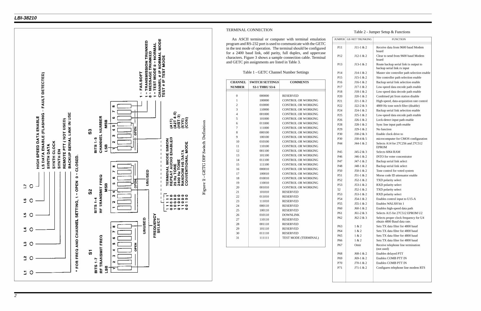
TERMINAL CONNECTION
An ASCII terminal or computer with terminal emulationprogram and RS-232 port is used to communicate with the GETCin the test mode of operation. The terminal should be configuredfor a 2400 baud link, odd parity, full duplex, and uppercasecharacters. Figure 3 shows a sample connection cable. Terminaland GETC pin assignments are listed in Table 3.
Table 1 - GETC Channel Number Settings
CHANNEL SWITCH SETTINGS COMMENTS
NUMBER S3-1 THRU S3-6
0 000000 RESERVED
1 100000 CONTROL OR WORKING
2 010000 CONTROL OR WORKING
3 110000 CONTROL OR WORKING
4 001000 CONTROL OR WORKING
5 101000 CONTROL OR WORKING
6 011000 CONTROL OR WORKING
7 111000 CONTROL OR WORKING
8 000100 CONTROL OR WORKING
9 100100 CONTROL OR WORKING
10 010100 CONTROL OR WORKING
11 110100 CONTROL OR WORKING
12 001100 CONTROL OR WORKING
13 101100 CONTROL OR WORKING
14 011100 CONTROL OR WORKING
15 111100 CONTROL OR WORKING
16 000010 CONTROL OR WORKING
17 100010 CONTROL OR WORKING
18 010010 CONTROL OR WORKING
19 110010 CONTROL OR WORKING
20 001010 CONTROL OR WORKING
21 101010 RESERVED
22 011010 RESERVED
23 111010 RESERVED
24 000110 RESERVED
25 100110 RESERVED
26 010110 DOWNLINK
27 110110 RESERVED
28 001110 RESERVED
29 101110 RESERVED
30 011110 RESERVED
31 111111 TEST MODE (TERMINAL)
JUMPER GE-NET TRUNKING FUNCTION
P11 J11-1 & 2 Receive data from 9600 baud Modemboard
P12 J12-1 & 2 Clear to send from 9600 baud Modemboard
P13 J13-1 & 2 Route backup serial link tx output tobackup serial link rx input
P14 J14-1 & 2 Master site controller path selection enable
P15 J15-1 & 2 Site controller path selection enable
P16 J16-1 & 2 Backup serial link selection enable
P17 J17-1 & 2 Low-speed data encode path enable
P18 J18-1 & 2 Low-speed data decode path enable
P20 J20-1 & 2 Combined ptt from station disable
P21 J21-1 & 2 High-speed, data-acquisition rate control
P22 J22-2 & 3 4800 Hz tone notch filter (disable)
P24 J24-1 & 2 Backup serial link selection enable
P25 J25-1 & 2 Low-speed data encode path enable
P26 J26-1 & 2 Lock-detect input path enable
P28 J28-1 & 2 Sync line input path enable
P29 J29-1 & 2 No function
P30 J30-2 & 3 Enable clock drive to
P30 J30-4 & 5 microcomputer for CMOS configuration
P44 J44-1 & 2 Selects A14 for 27C256 and 27C512EPROM
P45 J45-2 & 3 Selects 6064 RAM
P46 J46-1 & 2 INTO for voter concentrator
P47 J47-1 & 2 Backup serial link select
P48 J48-1 & 2 Backup serial link select
P50 J50-1 & 2 Tone control for voted system
P51 J51-1 & 2 Morse code ID attenuator enable
P52 J52-1 & 2 TXD polarity select
P53 J53-1 & 2 RXD polarity select
52 J52-1 & 2 TXD polarity select
P53 J53-1 & 2 RXD polarity select
P54 J54-1 & 2 Enables control input to U15-A
P55 J55-1 & 2 Enables WALSH bit 1
P60 J60-1 & 2 Enables high-speed data path
P61 J61-2 & 3 Selects A15 for 27C512 EPROM U2
P62 J62-2 & 3 Selects proper clock frequency for U4obtain 4800 Baud data rate.
P63 1 & 2 Sets TX data filter for 4800 baud
P64 1 & 2 Sets TX data filter for 4800 baud
P65 1 & 2 Sets TX data filter for 4800 baud
P66 1 & 2 Sets TX data filter for 4800 baud
P67 Omit Receive telephone line termination(not used)
P68 J68-1 & 2 Enables delayed PTT
P69 J69-1 & 2 Enables COMB PTT IN
P70 J70-1 & 2 Enables COMB PTT IN
P71 J71-1 & 2 Configures telephone line modem RTS
Table 2 - Jumper Setup & Functions
LBI-38210
2
This connection cable may be used any time the terminal isused during a GETC test procedure. Characters that are typedfrom the keyboard are followed by RETURN(ENTER). A keypress on the keyboard (such as ESC, TAB, or RETURN) isindicated by the key name enclosed in square brackets [KEYPRESS]. Control functions are indicated by CTRL - (CON-TROL CHARACTER), such as CTRL-Z to indicate the Z ispressed while holding down the CTRL key. If variable data orcommands are to be entered, they will be enclosed in anglebrackets <VARIABLE DATA>. Variable data depends on yourparticular application or test. Type the appropriate response (donot include brackets) and follow by a return if required.
POWER SUPPLY TEST (Bench Test)
1. Connect power supply to GETC connector J10 (pin 1 is +13.8V and pin 2 is ground).
2. Turn on the power supply and verify the current drawn doesnot exceed 700 mA (1.2 A with modem board installed). Ifcurrent is exceeded, check power supply circuitry beforeproceeding.
3. Connect a frequency counter or oscilloscope to TP104 andverify the presence of the 4800 Hz clock. If the clock ismissing, check modem U4 and associated circuitry.
4. Verify the presence of the following voltages:
MONITOR POINT VOLTAGE CHECK IF MISSINGOR INCORRECT
TP110 +5.0+/-0.25 Regulator board TP111 +5.0+/-0.25 Regulator board TP108 -12.0 +/ 1.2 -12-volt power supply TP109 +12.0 +/ 1.2 +12-volt power supply
MICROCOMPUTER CLOCK TEST
Equipment Required
• Frequency Counter
Test Procedure
1. Connect frequency counter to J30-3.
2. Verify the microcomputer clock frequency is 11.0592 MHz+ 500 Hz.
OFF-SITE TEST
The off site test is used to test the GETC in a laboratoryenvironment or under bench test. This section outlines the testingof the GETC as a stand alone unit outside of the station. However,these same tests can be done with the unit installed in the stationif connectors J6, J7, J8, and J19 are disconnected from the GETCboard during the tests.
Equipment Required
The equipment necessary for the off site test includes:
1. HP-6286A (or equivalent) DC power supply with currentlimit.
2. Tektronix-468 (or equivalent) digital storage scope.
3. HP-3312A (or equivalent) Function Generator.
4. Fluke-1920A (or equivalent) Frequency Counter.
5. Data Technology Model 30 digital Multimeter or equiva-lent.
6. Triplett Model 630-PL Type 5 VOM or equivalent.
7. ASCII Terminal or Computer with terminal connectionprogram.
8. HP-334A (or equivalent) Distortion Analyzer.
Preliminary Setup
1. Set switches S3-1 thru S3-6 to their off (open) positions.
2. Connect the terminal or computer to the GETC mastercommunication link (J8). Refer to Table 3 for GETC andRS-232C pin assignments.
3. Configure jumpers as shown in Table 2 if not already setup.
4. Move jumpers from J46-1&2 to J46-2&3 and from J51-1&2 to J51-2&3.
Serial Link Test
1. Apply power to the GETC (or press RESET switch S4 ifpower is already applied). The terminal will display theSIMON welcome message. If the welcome message doesnot appear, check the following:
• Check terminal hookup
• Check for +5 volts at U14-4 (SITE RX EN)
• Check reset circuitry
• Check for serial data on the TX and RX lines
2. Execute the <BCL> command (backup communicationslink) on the terminal. Press [RETURN] and verify thatterminal communication on the master link is inoperative.
3. Move the terminal from the master (J8) to the backup link(J19). Press [RETURN] and verify that terminal commu-nication on the backup link is operative by executing the command.
4. Execute the <MCL> command (master communicationslink) on the terminal. Press [RETURN] and verify thatterminal communication on the backup link is inoperative.
5. Move the terminal from the backup (J19) to the master (J8)link. Press [RETURN] and verify that terminal communi-cation on the master link is operative by executing the command.
EPROM Test
Execute the command CHK O-FFFF. Verify the terminalresponse of "CHECKSUM=OO".
RAM Test
Execute the command <TMX OOO-1FFF> to check U4.Verify the terminal response of "SIX PATTERNS TO CHECKOK".
Reset Circuit Test
1. Lower the input power to 6 volts.
2. Raise the input power to 9 volts. Verify the GETC wel-come message to the terminal.
Watchdog Timer Test
1. Execute the command <WAT> to verify Watchdog Timer(U4).
2. Verify the GETC response of the welcome message to theterminal after 5 seconds.
Input Buffer and Port Test
1. Move jumper P20 from J20-1&2 to J20-2&3.
2. Move jumper P26 from J26-1&2 to J26-2&3.
3. Move jumper P28 from J28-1&2 to J28-2&3.
4. Move jumper P12 from J12-1&2 to J12-2&3.
5. Connect J7-7, J7-9, J7-11, J7-13, and J3-25C to ground.
6. Execute the command <POR1>, and verify the terminalresponse of 10101010.
7. Execute the command <POR3>, and verify the terminalresponse of XX01XXXX, where X is any state.
8. Remove the ground from J7-7, J7-9, J7-11, J7-13, andJ3-25C.
9. Connect J7-6, J7-8, J7-10, J7-12, and J7-14 to ground.
10. Execute the command <POR1>, and verify the terminalresponse of 01010101.
11. Execute the command <POR3>, and verify the terminalresponse of XX10XXXX, where X is any state.
SIGNAL GETC LOGIC BD GETC SHELF TERMINAL EIAFROM PIN NUMBER PIN NUMBER RS-232C D-TYPEGETC CONNECTOR PIN
NUMBER
TXD J8-1 (MASTER) J100-3 (MASTER) PIN 3
TXD J19-1 (BACKUP) J101-3 (BACKUP) PIN 3
RXD J8-2 (MASTER) J100-2 (MASTER) PIN 2
RXD J19-2 (BACKUP) J101-2 (BACKUP) PIN 2
GND J8-3 (MASTER) J100-1 (MASTER) PIN 7
GND J19-3 (BACKUP) J101-1 (BACKUP) PIN 7
Table 3 - GETC and RS-232C Pin Assignments
Figure 3 - Terminal-To-GETC Connection Cable
LBI-38210
3

12. Remove the ground from J7-6, J7-8, J7-10, J7-12 andJ7-14.
13. Move jumper P20 from J20-2&3 to J20-1&2.
14. Move jumper P26 from J26-2&3 to J26-1&2.
15. Move jumper P28 from J28-2&3 to J28-1&2.
16. Move jumper P12 from J12-2&3 to J12-1&2.
High Speed Data Test
1. Jumper J7-2 to J7-4.
2. Execute the command <MDS 0>.
3. Execute the command <BER DE-00=10>, and verify theterminal response of:
"RECEIVE ERROR COUNT=0000 RECEIVE CHECK-SUM=00188123"
which continually updates every 20 seconds.
4. Enter CTRL-Z or [ESC] to end the test. Remove thejumper from J7-2 and J7-4.
Low-Speed Data Encode/Decode Test
1. Move jumper on J15 to 2&3.
2. Place a 10K pullup on J15-1 to 5 volts.
3. Execute the command <XBY B800=B6>.
4. Monitor the following points using an oscilloscope.
MONITOR POINT LOGIC LEVELU38-2 0U38-5 1U34-10 0J19-6 1J15-1 0U38-15 1U38-16 0U38-19 1
5. Enter CTRL-Z or [ESC].
6. Execute the command <XBY B800=49>.
Output Latch and Buffer Test
NO. STEP TEST LOGICPOINT LEVEL
1. Move jumper P14 from J14-1&2 to J14-2&3.
2. Move jumper P24 from J24-1&2 to J24-2&3.
3. Move jumper P25 from J25-1&2 to J25-2&3.
4. Move jumper P20 from J20-1&2 to J20-2&3.
5. Install a 10K resistor from J7-14 to ground.
6. Install a 10K resistor from theopen collector points (OC) to+13.8 volts.
7. Execute the command<XBY A800=52>.
8. Execute the command<XBY B000=42>.
9. Connect J7-6 to ground.
J6-1 1J6-2 1J6-3 1J6-4 0J6-5 1J6-10 1J6-11 0J6-12 1J6-13 0J6-14 1J6-15 1J6-16 1J7-14 <0.5VJ7-15 <0.5VJ7-16 0J9-1 >10VJ3-25A <0.5VJ3-13C 1H1 (L7) OFFH2 (L6) ONH3 (L5) OFF
Indicators H4 (L4) ONH5 (L3) ONH6 (L2) OFFH7 (L1) OFF
Reset the GETC to terminate this testNOTE
Unless otherwise specified, a logic one is defined as 13.8
+ 0.5 volts, and a logic zero is defined as 0 + 0.5 volts.
NOTE
NO. STEP TEST LOGICPOINT LEVEL
10. Execute the command<XBY B000=B9>.
11. Execute the command<XBY A800=AD>.
12. Connect J7-6 to ground.
J6-1 0J6-2 0J6-3 0J6-4 1J6-5 0J6-10 0J6-11 1J6-12 0J6-13 1J6-14 0J6-15 1J6-16 0J7-14 >7VJ7-15 >7VJ7-16 1J9-1 <-10VJ3-25A >3.5VJ3-13C 0H1 (L7) ONH2 (L6) OFFH3 (L5) ON
Indicators H4 (L4) OFFH5 (L3) OFFH6 (L2) ONH7 (L1) ON
13. Execute the command<XBY A800=00>.
14. Execute the command<XBY B000=OC>.Do not connect J7-6 toground.
J6-1 1J6-2 1J6-3 1J6-4 1J6-5 1J6-10 1J6-11 1J6-12 1J6-13 1J6-14 1J6-15 1J6-16 1J7-14 >7VJ7-15 >0.5VJ7-16 1J9-1 10VJ3-25A <0.5VJ3-13C 0
NO. STEP TEST LOGICPOINT LEVEL
H1 (L7) OFFH2 (L6) OFFH3 (L5) OFF
Indicators H4 (L4) OFFH5 (L3) OFFH6 (L2) OFFH7 (L1) OFF
15. Execute the command<XBY B000=08>.
16. Execute the command<XBY A800=80>.Do not connect J7-6 to ground.
J6-1 1J6-2 0J6-3 1J6-4 1J6-5 1J6-10 1J6-11 1J6-12 1J6-13 1J6-14 1J6-15 1J6-16 1J7-14 >7VJ7-15 >7VJ7-16 1J9-1 >10VJ3-25A <0.5VJ3-13C 0H1 (L7) OFFH2 (L6) OFFH3 (L5) OFF
Indicators H4 (L4) OFFH5 (L3) OFFH6 (L2) OFFH7 (L1) OFF
17. Move jumper P20 from J20-2&3to J20-1&2.
18. Move jumper P14 from J14-2&3to J14-1&2.
19. Move jumper P24 from J24-2&3to J24-1&2.
20. Move jumper P25 from J25-2&3to J25-1&2.
Reset the GETC to terminate this test
NOTE
LBI-38210
4

7. Monitor the following points using an oscilloscope.
MONITOR POINT LOGIC LEVELU38-2 1U38-5 0U34-10 1J19-6 0J15-1 1U38-15 0U38-16 1U38-19 0
8. Jumper J19-5 to J7-2.
9. Connect an oscilloscope to J19-5.
10. Execute the commands and verify the responses listed below.
11. Enter CTRL-Z or [ESC] to end the test.
12. Move jumper P15 back to J15-1&2.
DIP Switch Test
1. Execute the <DSW> command and verify the settings of DIPswitches, S1, S2, and S3. The terminal display is as shown:
"------ ------ ------"1 8 1 8 1 8
S1 S2 S3
An open (or OFF) on the DIP switch is displayed as a "1",while a closed (or ON) is displayed a "0".
This test continually updates the terminal display at eachDIP switch setting change. Verify all switches are func-tional by testing both the open and closed positions.
2. Enter CTRL-Z or [ESC] to end the test. Set S3-1 thru S3-6to open.
High Speed Data Filter Test
1. Monitor J7-4 as the output.
2. Execute the command
<FNT1>. Verify 600 Hz signal on J7-4.
3. Execute the command <FNT2>. Verify 1200 Hz signal onJ7-4.
4. Execute the command <FNT3>. Verify that the generated2400 Hz signal has approximately the same amplitude as insteps 3 and 4 and closely approximates a sinusoid. Typicaloutput level is 1 volt RMS when R31 is adjusted for rateddeviation.
Test Completion
Reposition all jumpers as shown in Table 2 before placing theGETC back in service.
ON-SITE TEST
This test is used to test the GETC at the system site locationusing limited tools and equipment. This procedure is a quickin-circuit functional test of the GETC in the station. DIP switchtest modes are normally used to set up the station data, audio, andpower levels. However, these can also be used to check basicoperation of the GETC as well. Table 4 shows the available DIPswitch tests.
Equipment Required
The equipment necessary for the on-site test includes:
1. Tektronix 468 (or equivalent) digital storage scope.
2. Triplett Model 630-PL Type 5 VOM or equivalent.
Preliminary Setup
1. Make sure station power is on and all jumpers are set accord-ing to Table 2.
2. Slide the GETC shelf out to gain access to the DIP switcheslocated near the front panel.
3. Select the desired test frequency using S1 and S2. SeeAppendix A for frequency codes.
4. Take the station "off-line" by setting S3-1 through S3-6 tothe open position and then momentarily pushing the GETCreset button.
Power Supply Test
1. Check to see that 13.8 volt power is present to the GETCon J10 (pin 1 is +13.8 V and pin 2 is ground).
2. Connect a frequency counter or oscilloscope to TP104 andverify the presence of the 4800 Hz clock. If the clock ismissing, check modem U4 and associated circuitry.
3. Verify the presence of the following voltages:
MONITOR POINT VOLTAGE CHECK IF MISSINGOR INCORRECT
TP110 +5.0+/-0.25 Regulator board TP111 +5.0+/-0.25 Regulator board TP108 -12.0 +/ 1.2 -12-volt power supply TP109 +12.0 +/ 1.2 +12-volt power supply
Microcomputer & System Clock Test
1. Check for a clock frequency of 11.0592 MHz on J30-3 andJ62-1.
2. Check for a 5.5296 MHz clock signal on J62-2&3.
3. Verify a 4800 Hz clock signal is present on TP104.
Low-speed Data Encode/Decode Test
1. Set up S3 for Test (B) as shown in Table 4, and reset theGETC. Make sure the receiver is squelched.
2. Check for a 25 Hz digital square wave on U38-2 andU38-5.
3. Check for a 2 volt peak-to-peak 25 Hz filtered square waveat J19-5 (Subaudible data encode port). See Figure 5 forexpected output.
4. Inject an on channel RF signal into the receiver modulatedwith a 150 Hz tone at + 0.2 kHz deviation.
5. Check for a 150 Hz digital square wave on J18-1&2(Subaudible RX data).
High-speed Data Encode/Decode Test
1. Set up S3 for Test (C) as shown in Table 4, and reset theGETC.
2. Check for a 2400 Hz digital square wave on TP101 (Mo-dem TX data).
3. Check for a 2.8 volt peak-to-peak 2400 Hz sine wave atJ7-4 (Modulation port). This level may vary slightly de-pending on the the data deviation pot R31.
4. Inject an on channel RF signal into the receiver modulatedwith a 2400 Hz tone at + 0.5 kHz deviation.
5. Check for a 2400 Hz digital square wave on TP103 (Mo-dem RX data).
Test Completion
1. Set the GETC DIP switches back to the operational con-figuration for the station.
2. Reset the GETC to put the station back on line. Verify thatthe station comes back up as either a voice channel or acontrol channel.
3. Slide the GETC back into the station shelf.
STATION TEST AND ADJUSTMENT
The station test is used to test the station and to performrepeat audio, high speed data, and low speed data adjustments.This section describes the adjustments of the GETC as part ofa station.
Equipment Required
The equipment necessary for the station test includes:
1. HP-8920A Communications Test Set or equivalent.
2. Tektronix 468 (or equivalent) digital storage scope.
3. HP-3312A (or equivalent) Function Generator.
4. Fluke-1920A (or equivalent) Frequency Counter.
5. Data Technology Model 30 (or equivalent) digital Mul-timeter.
6. Triplett Model 630-PL Type 5 (or equivalent) VOM.
7. HP-334A (or equivalent) Distortion Analyzer
COMMAND FREQUENCY AMPLITUDE ON FREQUENCY
ON J19-5(HZ) J19-5(VP-P) OF SQUARE-
CENTERED AT WAVE ON J18-1 (HZ)
LSH 1-1 10 2.0 + 0.25 10
LSH 1-2 100 2.0 + 0.25 100
LSH 1-3 200 2.0 + 0.25 200
LSH 1-4 1000 -32 dB of 2.0 UNDEFINED
LSH 2-1 10 1.0 + 0.25 10
LSH 2-2 100 1.0 + 0.25 100
LSH 2-3 200 1.0 + 0.25 200
LSH 2-4 1000 -32 dB of 1.0 UNDEFINED
LSH 3-1 10 3.5 + 0.5 10
LSH 3-2 100 3.5 + 0.5 100
LSH 3-3 200 3.5 + 0.5 200
LBI-38210
5

The GETC can be DIP switch programmed to enter simpletest mode operation. In this mode, single test function com-mands can be executed without need of a video terminal.Entering any of the test functions will load the synthesizerwith the channel setting from DIP switches S1, S2 and thenexecute a function selected with DIP switches S3-1 throughS3-6. Each test function is invoked by setting DIP switchesS3-1 through S3-6 to the desired test function and thenresetting the GETC. Table 4 lists the available tests.
Setup
Connect the test equipment to the station unit as shown inFigure 4. Select the desired test frequency using DIP switchesS1 and S2 located on the GETC shelf (see Appendix A). Theremaining DIP switch settings must be selected for each test. Alogic ’1’ corresponds to an ’OPEN’ switch while a logic ’0’ isselected by the ’CLOSED’ position.
Low Frequency Adjustment
1. Remove all signals from the receiver input and make surethe squelch is fully muted.
2. Set up DIP switches for test "A" and reset GETC.
3. Connect function generator (5 Hz square wave, 3 V peak)to exciter module J902 pin 2.
4. Set R83 (TONE DATA ADJ.) on the exciter module fullyclockwise for maximum subaudible data deviation.
5. View the demodulated 5 Hz square wave on a HP8920Acommunications test set with its output connected to a DCcoupled oscilloscope. The HP8920A should be configuredas an FM demodulator with settings as follows: filter-1 <20Hz HPF, filter-2 3 kHz LPF, de-emphasis off, scope toinput. Detailed instructions for the HP8920A follow:
A Apply power. This configures the instrument with itsdefault settings. DO NOT PRESS THE BASE KEYAT ANY TIME. THIS WILL CHANGE THE DE-FAULT SETTINGS AND AFFECT TEST CON-FIGURATION!.
B Press the TX key. This configures the analyzer fortransmitter tests and displays the TX TEST screen.
C Turn the CURSOR CONTROL knob until the cursoris positioned next to the Tune Mode selections(Auto/Manual). Pressing the knob toggles betweenchoices by underlining the preferred mode. SelectManual (Auto/Manual).
D In a similar manner, move the cursor to the Input Portposition and select RF in.
E Move the cursor to the AF Anal In position and pressthe knob; a menu will be displayed. Move the cursorto FM Demod and select it BY pressing the knobagain.
F In a similar manner, set Filter 1 to <20 Hz HPF andFilter 2 to 3 kHz LPF.
G Toggle the De-emphasis setting to Off.
H Set the Detector to Pk+-Max.
I Move the cursor to the To Screen menu and select AFANL . The display will change to the AF ANALYZERscreen.
J Move to the Scope To selection and select Input.
K Move the cursor to the To Screen menu and select RFANL . The display will change to the RF ANALYZERscreen.
L Move the cursor to the Tune Freq position. Press theknob to highlight the frequency then press the INCRSET button. Enter 500Hz using the numerical key padand the Hz button.
M This completes the entry of the test configuration. Theconfiguration can now be saved for recall by pressingSHIFT then SAVE, and selecting an option from theSave menu or by using the numerical key pad. To usethe numerical key pad, enter one or more digits fol-lowed by the ENTER key.
N This completes the setup of the HP-8920A.
6. Adjust R78 (DATA SYN ADJ) on the exciter module untilthe best square wave (5 Hz) is obtained.
7. Remove function generator from the exciter module J902 pin2. Set up DIP switches for test "B" and reset the GETC.
8. Adjust R83 (TONE DATA ADJ) on the exciter module for0.5 + 0.05 kHz deviation.
High Speed 4800 Baud Data Adjustment
1. Set up DIP switches for test "C" and reset the GETC.
2. Adjust R31 on the GETC shelf assembly to obtain 1.5 + 0.1kHz deviation. Verify the generated 2400 Hz tone nearlyapproximates a sine wave.
3. Set up DIP switches for test "D" and reset the GETC.
4. Verify the 4800 baud EYE pattern is generated and that theoutput is between + 1.4 kHz and + 1.7 kHz deviation. SeeFigure 6 for typical EYE pattern.
Repeat Audio Adjustment
1. Set up DIP switches for test "A" and reset the GETC.
2. Inject an on channel carrier (-50 dBm) with a 1 kHz tone @+ 1.5 kHz deviation.
3. Check the audio level at the Volume Squelch HI signal on theaudio board output located inside the receiver/exciter door.Adjust R608 on the audio board if necessary to obtain 1 voltRMS + 50 mV at the output.
4. Adjust R60 (REPEAT AUDIO) on the control shelf assemblyfully clockwise in order to overdrive the modulator and causethe exciter limiter to become active.
5. Adjust R71 (VOICE LVL ADJ) on the Exciter assembly toproduce between 1.9 and 2.0 kHz deviation measured by theservice monitor.
6. Readjust R60 (REPEAT AUDIO) on the control shelf toachieve + 1.5 kHz deviation.
7. Raise the input deviation to + 2.5 kHz. Verify the outputdeviation does not exceed + 2.0 kHz.
Repeater Operation
1. Set up DIP switches for test "E" and reset the GETC.
2. Inject a 1 kHz tone at 1.5 kHz deviation into the receiver inputand set the squelch for 10 dB SINAD opening level.
3. Raise the RF input level to -50 dBm and verify the repeatedtone is 1000 Hz at 1.5 + 0.1 kHz deviation at the transmitteroutput.
4. Remove the signal input and verify that the station unkeys.Insert the signal input and verify that the station keys.
TRUNKING TEST
The trunking test is used to test the GETC as part of afunctional system.
Equipment Required
• Single-channel trunked system (control channel andworking channel).
• Trunked mobiles or portables.
Test Procedure
1. Set the mobile or portable and the site controller to thefrequencies and channel numbers used for the control andworking channels.
2. Configure the control and working channels for transmissiontrunked operation and forced select failsoft operation (S3-7and S3-8 open).
3. Key the mobile or portable on a standard group call.
4. Verify the mobile/portable unit keys once on the controlchannel and then keys a second time followed by open voicecommunication.
5. Disconnect drive to the RF PA on the control channel. VerifyL6 begins flashing and the other channel becomes control(see Figure 1).
6. Reconnect the PA drive on the station being tested. Verify L6stops flashing within 30 seconds and the station becomes aworking channel.
7. Repeat steps (4), (5), and (6).
8. Set the DIP switches as needed to achieve normal systemoperation before resetting the GETC to put it back in fullservice.
TEST S3-1 S3-6 FUNCTIONS PERFORMED
(A) 000001 Key transmitter and enable repeataudio path.
(B) 100001 Key transmitter, enable repeat audiopath and send continuous 25 Hz data.
(C) 010001 Key transmitter, enable high speeddata path and send continuous 2400 Hz tone.
(D) 110001 Key transmitter, enable high speeddata path and send continuous random high speed data.
(E) 001001 Conventional mode, key transmitterand enable repeat audio when carrier is present.
101001 UNDEFINED011111 UNDEFINED
Table 4 - DIP Switch Test Configuration
LBI-38210
6

Figure 6 - Typical EYE Pattern
Figure 5 - 25 Hz Squarewave (Typical)
Figure 4 - Station Test Setup
LBI-38210
7

APPENDIX A
GETC FREQUENCY SELECTIONSWITCH SETTINGS

TX(MHZ) S1,1-7 S2,1-4 TX(MHZ) S1,1-7 S2,1-4 TX(MHZ) S1,1-7 S2,1-4
936.5125 1001111 0000 937.0125 1000010 1000 937.5125 1001001 1000936.5250 0101111 0000 937.0250 0100010 1000 937.5250 0101001 1000936.5375 1101111 0000 937.0375 1100010 1000 937.5375 1101001 1000936.5500 0011111 0000 937.0500 0010010 1000 937.5500 0011001 1000936.5625 1011111 0000 937.0625 1010010 1000 937.5625 1011001 1000936.5750 0111111 0000 937.0750 0110010 1000 937.5750 0111001 1000936.5875 1111111 0000 937.0875 1110010 1000 937.5875 1111001 1000936.6000 0000000 1000 937.1000 0001010 1000 937.6000 0000101 1000936.6125 1000000 1000 937.1125 1001010 1000 937.6125 1000101 1000936.6250 0100000 1000 937.1250 0101010 1000 937.6250 0100101 1000936.6375 1100000 1000 937.1375 1101010 1000 937.6375 1100101 1000936.6500 0010000 1000 937.1500 0011010 1000 937.6500 0010101 1000936.6625 1010000 1000 937.1625 1011010 1000 937.6625 1010101 1000936.6750 0110000 1000 937.1750 0111010 1000 937.6750 0110101 1000936.6875 1110000 1000 937.1875 1111010 1000 937.6875 1110101 1000936.7000 0001000 1000 937.2000 0000110 1000 937.7000 0001101 1000936.7125 1001000 1000 937.2125 1000110 1000 937.7125 1001101 1000936.7250 0101000 1000 937.2250 0100110 1000 937.7250 0101101 1000936.7375 1101000 1000 937.2375 1100110 1000 937.7375 1101101 1000936.7500 0011000 1000 937.2500 0010110 1000 937.7500 0011101 1000936.7625 1011000 1000 937.2625 1010110 1000 937.7625 1011101 1000936.7750 0111000 1000 937.2750 0110110 1000 937.7750 0111101 1000936.7875 1111000 1000 937.2875 1110110 1000 937.7875 1111101 1000936.8000 0000100 1000 937.3000 0001110 1000 937.8000 0000011 1000936.8125 1000100 1000 937.3125 1001110 1000 937.8125 1000011 1000936.8250 0100100 1000 937.3250 0101110 1000 937.8250 0100011 1000936.8375 1100100 1000 937.3375 1101110 1000 937.8375 1100011 1000936.8500 0010100 1000 937.3500 0011110 1000 937.8500 0010011 1000936.8625 1010100 1000 937.3625 1011110 1000 937.8625 1010011 1000936.8750 0110100 1000 937.3750 0111110 1000 937.8750 0110011 1000936.8875 1110100 1000 937.3875 1111110 1000 937.8875 1110011 1000936.9000 0001100 1000 937.4000 0000001 1000 937.9000 0001011 1000936.9125 1001100 1000 937.4125 1000001 1000 937.9125 1001011 1000936.9250 0101100 1000 937.4250 0100001 1000 937.9250 0101011 1000936.9375 1101100 1000 937.4375 1100001 1000 937.9375 1101011 1000936.9500 0011100 1000 937.4500 0010001 1000 937.9500 0011011 1000936.9625 1011100 1000 937.4625 1010001 1000 937.9625 1011011 1000936.9750 0111100 1000 937.4750 0110001 1000 937.9750 0111011 1000936.9875 1111100 1000 937.4875 1110001 1000 937.9875 1111011 1000937.0000 0000010 1000 937.5000 0001001 1000 938.0000 0000111 1000
0 = CLOSED or ON 1 = OPEN or OFF
TX(MHZ) S1,1-7 S2,1-4 TX(MHZ) S1,1-7 S2,1-4 TX(MHZ) S1,1-7 S2,1-4
935.0125 1000000 0000 935.5125 1001010 0000 936.0125 1000101 0000935.0250 0100000 0000 935.5250 0101010 0000 936.0250 0100101 0000935.0375 1100000 0000 935.5375 1101010 0000 936.0375 1100101 0000935.0500 0010000 0000 935.5500 0011010 0000 936.0500 0010101 0000935.0625 1010000 0000 935.5625 1011010 0000 936.0625 1010101 0000935.0750 0110000 0000 935.5750 0111010 0000 936.0750 0110101 0000935.0875 1110000 0000 935.5875 1111010 0000 936.0875 1110101 0000935.1000 0001000 0000 935.6000 0000110 0000 936.1000 0001101 0000935.1125 1001000 0000 935.6125 1000110 0000 936.1125 1001101 0000935.1250 0101000 0000 935.6250 0100110 0000 936.1250 0101101 0000935.1375 1101000 0000 935.6375 1100110 0000 936.1375 1101101 0000935.1500 0011000 0000 935.6500 0010110 0000 936.1500 0011101 0000935.1625 1011000 0000 935.6625 1010110 0000 936.1625 1011101 0000935.1750 0111000 0000 935.6750 0110110 0000 936.1750 0111101 0000935.1875 1111000 0000 935.6875 1110110 0000 936.1875 1111101 0000935.2000 0000100 0000 935.7000 0001110 0000 936.2000 0000011 0000935.2125 1000100 0000 935.7125 1001110 0000 936.2125 1000011 0000935.2250 0100100 0000 935.7250 0101110 0000 936.2250 0100011 0000935.2375 1100100 0000 935.7375 1101110 0000 936.2375 1100011 0000935.2500 0010100 0000 935.7500 0011110 0000 936.2500 0010011 0000935.2625 1010100 0000 935.7625 1011110 0000 936.2625 1010011 0000935.2750 0110100 0000 935.7750 0111110 0000 936.2750 0110011 0000935.2875 1110100 0000 935.7875 1111110 0000 936.2875 1110011 0000935.3000 0001100 0000 935.8000 0000001 0000 936.3000 0001011 0000935.3125 1001100 0000 935.8125 1000001 0000 936.3125 1001011 0000935.3250 0101100 0000 935.8250 0100001 0000 936.3250 0101011 0000935.3375 1101100 0000 935.8375 1100001 0000 936.3375 1101011 0000935.3500 0011100 0000 935.8500 0010001 0000 936.3500 0011011 0000935.3625 1011100 0000 935.8625 1010001 0000 936.3625 1011011 0000935.3750 0111100 0000 935.8750 0110001 0000 936.3750 0111011 0000935.3875 1111100 0000 935.8875 1110001 0000 936.3875 1111011 0000935.4000 0000010 0000 935.9000 0001001 0000 936.4000 0000111 0000935.4125 1000010 0000 935.9125 1001001 0000 936.4125 1000111 0000935.4250 0100010 0000 935.9250 0101001 0000 936.4250 0100111 0000935.4375 1100010 0000 935.9375 1101001 0000 936.4375 1100111 0000935.4500 0010010 0000 935.9500 0011001 0000 936.4500 0010111 0000935.4625 1010010 0000 935.9625 1011001 0000 936.4625 1010111 0000935.4750 0110010 0000 935.9750 0111001 0000 936.4750 0110111 0000935.4875 1110010 0000 935.9875 1111001 0000 936.4875 1110111 0000935.5000 0001010 0000 936.0000 0000101 0000 936.5000 0001111 0000
0 = CLOSED or ON 1 = OPEN or OFF
LBI-38210
A-1

TX(MHZ) S1,1-7 S2,1-4 TX(MHZ) S1,1-7 S2,1-4 TX(MHZ) S1,1-7 S2,1-4
938.0125 1000111 1000 938.5125 1001100 0100 939.0125 1000001 0100938.0250 0100111 1000 938.5250 0101100 0100 939.0250 0100001 0100938.0375 1100111 1000 938.5375 1101100 0100 939.0375 1100001 0100938.0500 0010111 1000 938.5500 0011100 0100 939.0500 0010001 0100938.0625 1010111 1000 938.5625 1011100 0100 939.0625 1010001 0100938.0750 0110111 1000 938.5750 0111100 0100 939.0750 0110001 0100938.0875 1110111 1000 938.5875 1111100 0100 939.0875 1110001 0100938.1000 0001111 1000 938.6000 0000010 0100 939.1000 0001001 0100938.1125 1001111 1000 938.6125 1000010 0100 939.1125 1001001 0100938.1250 0101111 1000 938.6250 0100010 0100 939.1250 0101001 0100938.1375 1101111 1000 938.6375 1100010 0100 939.1375 1101001 0100938.1500 0011111 1000 938.6500 0010010 0100 939.1500 0011001 0100938.1625 1011111 1000 938.6625 1010010 0100 939.1625 1011001 0100938.1750 0111111 1000 938.6750 0110010 0100 939.1750 0111001 0100938.1875 1111111 1000 938.6875 1110010 0100 939.1875 1111001 0100938.2000 0000000 0100 938.7000 0001010 0100 939.2000 0000101 0100938.2125 1000000 0100 938.7125 1001010 0100 939.2125 1000101 0100938.2250 0100000 0100 938.7250 0101010 0100 939.2250 0100101 0100938.2375 1100000 0100 938.7375 1101010 0100 939.2375 1100101 0100938.2500 0010000 0100 938.7500 0011010 0100 939.2500 0010101 0100938.2625 1010000 0100 938.7625 1011010 0100 939.2625 1010101 0100938.2750 0110000 0100 938.7750 0111010 0100 939.2750 0110101 0100938.2875 1110000 0100 938.7875 1111010 0100 939.2875 1110101 0100938.3000 0001000 0100 938.8000 0000110 0100 939.3000 0001101 0100938.3125 1001000 0100 938.8125 1000110 0100 939.3125 1001101 0100938.3250 0101000 0100 938.8250 0100110 0100 939.3250 0101101 0100938.3375 1101000 0100 938.8375 1100110 0100 939.3375 1101101 0100938.3500 0011000 0100 938.8500 0010110 0100 939.3500 0011101 0100938.3625 1011000 0100 938.8625 1010110 0100 939.3625 1011101 0100938.3750 0111000 0100 938.8750 0110110 0100 939.3750 0111101 0100938.3875 1111000 0100 938.8875 1110110 0100 939.3875 1111101 0100938.4000 0000100 0100 938.9000 0001110 0100 939.4000 0000011 0100938.4125 1000100 0100 938.9125 1001110 0100 939.4125 1000011 0100938.4250 0100100 0100 938.9250 0101110 0100 939.4250 0100011 0100938.4375 1100100 0100 938.9375 1101110 0100 939.4375 1100011 0100938.4500 0010100 0100 938.9500 0011110 0100 939.4500 0010011 0100938.5625 1010100 0100 938.9625 1011110 0100 939.4625 1010011 0100938.4750 0110100 0100 938.9750 0111110 0100 939.4750 0110011 0100938.4875 1110100 0100 938.9875 1111110 0100 939.4875 1110011 0100938.5000 0001100 0100 939.0000 0000001 0100 939.5000 0001011 0100
0 = CLOSED or ON 1 = OPEN or OFF
TX(MHZ) S1,1-7 S2,1-4 TX(MHZ) S1,1-7 S2,1-4 TX(MHZ) S1,1-7 S2,1-4
939.5125 1001011 0100 939.6750 0110111 0100 939.8375 1100000 1100939.5250 0101011 0100 939.6875 1110111 0100 939.8500 0010000 1100939.5375 1101011 0100 939.7000 0001111 0100 939.8625 1010000 1100939.5500 0011011 0100 939.7125 1001111 0100 939.8750 0110000 1100939.5625 1011011 0100 939.7250 0101111 0100 939.8875 1110000 1100939.5750 0111011 0100 939.7375 1101111 0100 939.9000 0001000 1100939.5875 1111011 0100 939.7500 0011111 0100 939.9125 1001000 1100939.6000 0000111 0100 939.7625 1011111 0100 939.9250 0101000 1100939.6125 1000111 0100 939.7750 0111111 0100 939.9375 1101000 1100939.6250 0100111 0100 939.7875 1111111 0100 939.9500 0011000 1100939.6375 1100111 0100 939.8000 0000000 1100 939.9625 1011000 1100939.6500 0010111 0100 939.8125 1000000 1100 939.9750 0111000 1100939.6625 1010111 0100 939.8250 0100000 1100 939.9875 1111000 1100
0 = CLOSED or ON 1 = OPEN or OFF
LBI-38210
A-2

This page intentionally left blank

APPENDIX BPARTS LIST
OUTLINE & SCHEMATIC DIAGRAMSADJUSTMENT AND TEST POINTS
TABLE OF CONTENTS
Page
Parts List . . . . . . . . . . . . . . . . . . . . . . . . . . . . . . . . . . . . . . . . . . . . . . . . . . . . . B-1
Regulator Asembly Diagram . . . . . . . . . . . . . . . . . . . . . . . . . . . . . . . . . . . . . . . . . . B-3
Cable Wiring Diagram . . . . . . . . . . . . . . . . . . . . . . . . . . . . . . . . . . . . . . . . . . . . . B-3
GETC Shelf Assembly Diagram . . . . . . . . . . . . . . . . . . . . . . . . . . . . . . . . . . . . . . . . B-4
GETC Board Outline Diagram . . . . . . . . . . . . . . . . . . . . . . . . . . . . . . . . . . . . . . . . . B-4
GETC Schematic Diagram . . . . . . . . . . . . . . . . . . . . . . . . . . . . . . . . . . . . . . . . . . . B-6
Adjustments and Test Points . . . . . . . . . . . . . . . . . . . . . . . . . . . . . . . . . . . . . . . . . . B-11

PARTS LIST LBI-38210
B-1

PARTS LISTLBI-38210
B-2

WIRING DIAGRAMASSEMBLY DIAGRAM
REGULATOR ASSEMBLY19C336816G2
(19C336816, Sh. 1, Rev. 6)
CABLE ASSEMBLY 19C336863G1(19C336866, Sh. 1, Rev. 0)
LBI-38210
B-3

ASSEMBLY DIAGRAM
GETCSHELF 19D901868G3
LBI-38210
B-4

OUTLINE DIAGRAM
GETC BOARD 19D902104G1
(19D902106, Rev. 4)(19A705536, Sh. 2, Rev. 2)
COMPONENT SIDE
(19D902106, Rev. 4)(19A705536, Sh. 3, Rev. 2)
SOLDER SIDE
LBI-38210
B-5

SCHEMATIC DIAGRAM
GETC SHELF 19D901868G3
LBI-38210
B-6

SCHEMATIC DIAGRAM
GETC SHELF 19D901868G3(19D902106, Sh. 2, Rev. 3)
LBI-38210
B-7

SCHEMATIC DIAGRAM
GETC SHELF19D901868G3(19D902106, Sh. 3, Rev. 2)
LBI-38210
B-8

SCHEMATIC DIAGRAM
GETC SHELF 19D901868G3(19D902106, Sh. 4, Rev. 5)
LBI-38210
B-9

SCHEMATIC DIAGRAM
GETC SHELF 19D901868G3(19D902106, Sh. 5,Rev. 3)
LBI-38210
B-10

SCHEMATIC DIAGRAM
GETC SHELF 19D901868G3(19D902106, Sh. 6, Rev. 2)
LBI-38210
B-11

ADJUSTMENT AND TEST POINTSLBI-38210
B-12

This page intentionally left blank
LBI-38210
B-13


![DIP SWITCHES KEYLOCK SWITCHES RoHS · 2018-01-04 · sp option d p oti n 17.50 [.689 in] orientation feature on switches with graphics or illuminated power symbol see standard single](https://static.fdocuments.net/doc/165x107/5f1a2c1f358b0a53d27f6e43/dip-switches-keylock-switches-rohs-2018-01-04-sp-option-d-p-oti-n-1750-689.jpg)