Layers, Colors, Linetypes, and Properties -...
20
67 Up and Running with AutoCAD® 2012: 2D and 3D Drawing and Modeling. © Elsevier Inc. All rights reserved. 2012 CHAPTER Layers, Colors, Linetypes, and Properties LEARNING OBJECTIVES Layers are an essential concept and need to be introduced before a serious drawing is attempted. In this chapter, we introduce layers and discuss the following: ● What are layers? ● Why use them? ● Creating and deleting layers ● Making a layer current ● Assigning layer colors ● Index color ● True color ● Color Books ● Layer Freeze/Thaw ● Layer On/Off ● Layer Lock/Unlock ● Loading and setting linetypes ● Properties Palette ● Match Properties ● Layers toolbar 3
Transcript of Layers, Colors, Linetypes, and Properties -...

67
Up and Running with AutoCAD® 2012: 2D and 3D Drawing and Modeling.
© Elsevier Inc. All rights reserved. 2012
CHAPTER
Layers, Colors, Linetypes, and Properties
LEARNING OBJECTIVES Layers are an essential concept and need to be introduced before a serious drawing is attempted. In this chapter, we introduce layers and discuss the following:
● What are layers?
● Why use them?
● Creating and deleting layers
● Making a layer current
● Assigning layer colors
● Index color
● True color
● Color Books
● Layer Freeze/Thaw
● Layer On/Off
● Layer Lock/Unlock
● Loading and setting linetypes
● Properties Palette
● Match Properties
● Layers toolbar
3
CH003.indd 67CH003.indd 67 6/29/2011 10:05:19 AM6/29/2011 10:05:19 AM

LEVEL 1 Chapters 1–10
68
Here, you learn all the remaining tools to begin creating a fl oor plan, which we start at the end of the chapter.
Estimated time for completion of chapter: 3 hours (lesson and project).
3.1 INTRODUCTION TO LAYERS Layers are our fi rst major topic after the previous chapters of basics. It is a very important concept in AutoCAD, and no designer or draftsperson would ever consider drawing anything more complex than a few lines without using them.
What Are Layers? “Layers” is a concept that allows you to group drawn geometry in distinct and separate categories according to similar features or a common theme. This allows you to exercise control over your drawing by, among other things, applying properties to the layers, such as assigning colors and linetypes. You can also manipulate each individual layer, making it visible or invisible for clarity, as well as being able to lock them to prevent editing.
For example, all the walls of a fl oor plan will exist on the “Walls” layer, all the doors on the “Doors” layer, windows on the “Windows” layer, and so on. You can think of layers as transparency sheets in an anatomy textbook, with each sheet showing a unique and distinct category of data (skeleton, muscle, circulatory system, etc.), but when viewed all at once they show the complete picture of a person. Similarly, in AutoCAD, there can be any number of layers, with all of them holding their respective data and combining into the complete design.
Why Use Them? As just stated, the key word here is control . If all your geometry were lumped together on one layer, as some beginners do, then whatever you do to one set of objects, you do to all; certainly not what you want. It is very important that you learn about layers early in your AutoCAD education, and apply them right away to your fi rst real drawing.
Let us take a look at the Layers Properties Manager. This is AutoCAD’s Layers dialog box, where everything important related to layers happens. Open a new fi le and, if you decide to use toolbars, also bring up the Layer toolbar. We take a closer look at that toolbar in Section 3.3 , but for now you need only the icon that calls up the Layers Property Manager .
Once you call up the layers property manager, you will see Figure 3.1
Examining the dialog box from left to right, notice the fi lters taking up some room on the left. We need not talk about fi lters until Chapter 12, and you can actually minimize that whole area by clicking the �� arrows. To the right of the fi lters, notice the main category headers such as “Status,” “Name,” “On,” and “Freeze.” Below the categories you fi nd the only existing layer thus far, 0, and its properties. Notice that it is white with a “continuous” linetype. Above the categories are some action buttons for creating and deleting layers, which we cover next.
Creating and Deleting Layers Assuming you are starting from a blank fi le, each new layer initially needs to be typed in according to what you (or the company you work for) require. To do that, you fi rst need to
CH003.indd 68CH003.indd 68 6/29/2011 10:05:19 AM6/29/2011 10:05:19 AM

CHAPTER 3 Layers, Colors, Linetypes, and Properties
69
FIGURE 3.1 AutoCAD 2012 Layer Properties Manager.
click on the 0 layer to make sure it is highlighted with the blue band. Then press the New Layer icon at the top of the layer box (two icons to the left of the red X), which looks like a sheet of paper with a sparkle next to it. You can also hold down the Alt key and press N. Either way, once you do that, a new band saying Layer 1 appears. Just type in your new layer name followed by Enter, and a new layer is created. Here are some helpful tips:
● If you notice that you made a spelling mistake after you already pressed Enter, you can just click back into the layer name once or twice until the cursor enters Edit mode and retype.
● Do not attempt to change the 0 layer’s name. It is the default layer and cannot be deleted or renamed.
● If you want to delete a layer (perhaps an accidentally made one), simply highlight the layer, and click the red X icon, or press Alt-D. If the layer contains nothing, it will be deleted.
Following this procedure, create the following three layers:
● A-Doors ● A-Walls ● A-Windows
What you should see is shown in Figure 3.2 . The letter A in front of each layer simply means Architectural.
Making a Layer Current The current layer is the active layer on which you can draw at any given moment. You are always on some layer (even if you are not immediately sure which one exactly). So, logically, if you are about to draw a wall, you should be on the A-Walls layer and so on. To specify what layer to have as current, either click on the green check mark button, to the right of the red X, or double-click on the layer name itself. At the very top left of the Layers dialog box it says “Current layer:” followed by the name of the layer. Check there if you are unsure what is what. For now, go ahead and make A-Walls the current layer.
Assigning Layer Colors Assigning colors to layers is very important and should be done as you create them or soon after. The reasons to have color are twofold. On the most basic level, a colorful drawing is more pleasant to look at on the screen, but more important, it is easier to interpret and work with. If,
CH003.indd 69CH003.indd 69 6/29/2011 10:05:19 AM6/29/2011 10:05:19 AM

LEVEL 1 Chapters 1–10
70
for example, your walls are green and you keep this in mind, then your eye is able to quickly see and assess the design. Likewise, yellow doors are easy to spot. This color separation greatly aids in drafting. Imagine a scenario where your building fl oor plan is made up of all white lines; you would be unable to tell one line from another. As that drawing grew more complex, all the lines would melt into one monochrome mess. Finally, colors are assigned pen thicknesses (an advanced topic) and contribute to more professional-looking output. We address this in Level 2.
To assign colors, let us turn our attention back to the Layers dialog box. Highlight, by clicking once, layer A-Walls. Now, follow the blue ribbon across until you see a box with the word white next to it. It will be under the Color column. Click on it, and the Select Color dialog box appears, as seen in Figure 3.3 .
FIGURE 3.2 Layer Properties Manager with three new layers.
FIGURE 3.3 Select Color, Index Color.
CH003.indd 70CH003.indd 70 6/29/2011 10:05:19 AM6/29/2011 10:05:19 AM

CHAPTER 3 Layers, Colors, Linetypes, and Properties
71
INDEX COLOR Let us take a tour of this Index Color tab. The two large 24 � 5 stripes of colors you immediately see at the top make up the AutoCAD Color Index (ACI), and it contains 240 colors. Do not be too quick in selecting one of those right away. Take a look below; there are two smaller color stripes. The rainbow-like stripes 1 through 9 are the ones in which we are most interested. If you take a close look, they are the primary colors and the 240 colors above them are just different shades of the primaries. You should always use up those nine colors fi rst—they are very distinct from each other—and only then move on to the others. Also this makes setting pen weights easier later down the road, as you need not scroll through dozens of colors to fi nd the ones you used.
The colors from left to right are Red→Yellow→Green→Cyan (not Aqua)→Blue→Magenta (not Maroon), then White and two shades of Gray, 8 and 9. The color stripe below that contains just additional shades of gray, and we do not need them for now. So, fi nally, pick a color for the A-Walls layer (green is what many architects use for walls), click on it, then press Enter; you are taken back to the Layers dialog box to assign more colors to more layers. Yellow is recommended for A-Doors and red for A-Windows.
TRUE COLOR There is more to colors, of course. Go back to the Select Color dialog box. Now, click the second tab, called True Color ( Figure 3.4 ). Here is where some experience in graphic design may come in handy.
The main color window you are looking at now contains over 16 million colors and should be familiar to you if you use Photoshop, Illustrator, PaintShop®, or any of those types of design programs. You can now move your mouse around, selecting colors based on the HSL method. HSL stands for H ue (the actual colors, moving across), S aturation (moving up or down), and L uminance (brighter or darker, moving the slider up or down next to the main window). You may also use the RGB (red, green, blue) model of color selection by using the drop-down selector at the upper right ( Figure 3.5 ). Whichever color you settle on is shown by both color models. Designers rarely use these colors for 2D work (where you want objects to be bright and visible), but do pick these more subtle colors for realistic-looking 3D models.
FIGURE 3.4 Select Color, HSL.
FIGURE 3.5 Select Color, RGB.
CH003.indd 71CH003.indd 71 6/29/2011 10:05:20 AM6/29/2011 10:05:20 AM

LEVEL 1 Chapters 1–10
72
COLOR BOOKS Here is where things get even fancier. Color Books are Pantone colors. If you are an architect or an interior designer, you already know what these are. If you are shaking your head and have never heard of Pantone, do not worry about it, chances are you will not need to use them. Just to try however, scroll through the palettes and select a color. Figure 3.6 is a screen shot of the Color Books tab.
FIGURE 3.6 Select Color, Color Books.
Layer Freeze/Thaw and On/Off Here, we come to a very important part of the Layers dialog box. Freeze and Thaw are opposites of the same command, one that makes a layer appear or disappear from view. The command freezes or thaws the layer for the entire drawing. Pick a layer, highlight it, follow the band across to the Freeze column and underneath you will fi nd a yellow sun icon. If you click on it, that layer “freezes” and the icon becomes a blue snowfl ake. Clicking again undoes the action. So what does freeze mean? It makes the layer (or more precisely all the objects on that layer) disappear from view, but remember, they are not deleted only invisible. You will use this feature routinely in drawings to control what is displayed. The On/Off feature represented by the lightbulb (yellow to blue and back) is essentially the same as Freeze/Thaw, with some subtle (and minor) details, so we do not go into them. You can use either method; although stay with Freeze/Thaw just to keep things consistent.
Layer Lock/Unlock This layer command, represented by the padlock, does exactly that; it locks the layer so you cannot edit or erase it. The layer remains visible but untouchable. The unlocked layer’s icon is blue and looks “unlocked,” while a locked layer’s padlock turns yellow and changes to a “locked” position. To let you know which layers are locked, the layers fade somewhat, so you can tell them apart from non-locked geometry. You can control the level of this fading via a slider on the Ribbon. Go to the Home tab, and drop down the arrow in the Layers category.
CH003.indd 72CH003.indd 72 6/29/2011 10:05:20 AM6/29/2011 10:05:20 AM

CHAPTER 3 Layers, Colors, Linetypes, and Properties
73
You see a slider that says “Locked layer fading.” Use it to make the locked layers darker or lighter to your liking.
Experiment with everything mentioned thus far to get a feel for layer controls. When done, make sure everything is reset (not locked or frozen) and click on the X in the upper corner of the layer box to close it.
3.2 INTRODUCTION TO LINETYPES Linetypes are the different lines that come with AutoCAD. As a designer, architect, or engineer, you may need a variety of lines to convey different ideas in your design. Just as in hand drafting, where you create Dashed, Hidden, Phantom, and other line types to show cabinets, demolition work, or hidden geometry in part design, in AutoCAD you load the lines and use them as necessary.
The idea here is to load them all in the beginning and then assign the linetypes to either a layer or sometimes just a few items. You can also load them as needed, but it is recommended to get this out of the way so you have them at your fi ngertips. The procedure to do so is as follows:
Step 1. Type in linetype and press Enter or choose Format→Linetype … from the cascading menu. The Linetype Manager ( Figure 3.7 ) appears. If it is full of linetypes, it means they have been loaded earlier. If not, and the Linetype Manager is empty, go on to Step 2.
Step 2. Press L oad… The Load or Reload Linetypes box comes up ( Figure 3.8 ).
FIGURE 3.7 Linetype Manager.
FIGURE 3.8 Load or Reload Linetypes.
Step 3. Position your mouse in the white empty space between the two columns (Linetype and Description) of the Load or Reload Linetypes box and right-click. The Select All/Clear All menu appears.
Step 4. Press Select All and every linetype in the left column turns blue (selected). Step 5. Press OK (and possibly a Yes to All as well) and the dialog box disappears. All the
linetypes are loaded now, so press OK again in the Linetype Manager and you are done.
CH003.indd 73CH003.indd 73 6/29/2011 10:05:21 AM6/29/2011 10:05:21 AM

LEVEL 1 Chapters 1–10
74
We can now use the loaded linetypes and assign a linetype to a layer. Go back to the Layers dialog box:
Step 1. Create a new layer called Hidden and assign a linetype to it (the “Hidden” linetype, naturally).
Step 2. Make sure the Hidden layer is highlighted with the blue bar, and move your mouse to the right until it matches up with the header category Linetype. It should say Continuous right now.
Step 3. Click on the word Continuous and the Select Linetype ( Figure 3.9 ) dialog box comes up with all your linetypes preloaded. If we did not load them earlier, the box would be practically empty and we would have to do the loading at that point.
Step 4. So, now all we have to do is scroll up and down the list to fi nd the appropriate linetype (Hidden in this case), select it, and press OK.
Make a note of the important linetypes for future reference: Center, Dashed, Divide, Hidden, and Phantom are some of the key ones. Ignore the ones named ACAD_ISO … for the simple reason that their names are not descriptive enough to recognize at a glance. Also, make a note of why there are three types of the same linetype (such as DASHED, DASHED2, and DASHEDX2). By checking the appearance carefully, you see that the scale is different. Finally, let us get back to the Layers dialog box. If you set your Hidden layer to Current, then everything you draw is a dashed line. Go ahead and try it out.
We conclude with one fi nal important note on linetypes. If you cannot see the linetype, and it appears as a solid line when it should be something else, chances are the scale is too small. Type in ltscale (linetype scale) and enter a larger number. This is mentioned again as a tip in Chapter 4.
3.3 INTRODUCTION TO PROPERTIES Sometimes, you need to change objects from one layer to another (perhaps because of an error in originally placing it on the incorrect layer or a later decision to change to another layer). Also, you may need to change the color, linetype, or other properties of objects. AutoCAD has a collection of tools to change the properties of objects, with the three most
FIGURE 3.9 Select Linetype.
CH003.indd 74CH003.indd 74 6/29/2011 10:05:21 AM6/29/2011 10:05:21 AM

CHAPTER 3 Layers, Colors, Linetypes, and Properties
75
common methods being the Properties palette, the Match Properties tool, and the Layer toolbar. We explore each in order.
Properties Palette
Look at the palette in detail from top to bottom. There are a number of categories (General, View, etc.), and a number of features that can be modifi ed in those categories (Color, Layer, Linetype, etc.). Also there are two columns, a gray one on the left and a mix of gray (inactive) and white (active) fi elds on the right. To use this palette fi rst draw several lines on your screen, each of which is on a different layer. Then, follow these steps:
FIGURE 3.10 Properties palette.
There are two other ways to bring up the Properties palette:
● Double-click on any geometry object (line, arc, etc.). ● Press Ctrl � 1.
Once you do any of these, the Properties box shown in Figure 3.10 appears.
CH003.indd 75CH003.indd 75 6/29/2011 10:05:21 AM6/29/2011 10:05:21 AM

LEVEL 1 Chapters 1–10
76
Step 1. First, make sure you have selected one or more items to change. They become dashed. If you selected two items, only those properties common to both that can be changed are available.
Step 2. In the Properties box, fi nd the category you want changed, color, for example. Step 3. Click on the right-hand column directly across from that property. Step 4. An arrow drops down. Click on it and view the choices within that category. Step 5. Select the different property that you want the new objects to have, such as a new
color. Step 6. Close the Properties box (the X in the upper corner) and press Esc once or twice; the
objects have that property. The Properties toolbar is a quick, easy way to change a number of properties but there is another way, shown next.
Match Properties
This is a really great way to very quickly match up the properties of one object with the properties of another. The procedure is simple. Start the command via the preceding methods, select the fi rst object whose properties you like, then click on another object that you want to have those properties.
Match Properties matches almost anything: layers, colors, linetypes, linetype scales, text sizes, hatch patterns, and many more factors. Finally, we have the Layers toolbar, which has its own method of layer changes and deserves its own separate discussion.
Layers Toolbar The Layers toolbar is shown in Figure 3.11 with the three layers added. If you want to use the toolbars, then add it to your on-screen collection, and use it throughout the remainder of the chapters.
FIGURE 3.11 Layers toolbar.
To change layers using this toolbar, simply select whatever you would like to change to another layer (what you selected becomes dashed), then drop down the Layer menu in the toolbar and pick the new layer on which you want the highlighted geometry to go, and it changes. You may have to press Esc to deselect the layer(s) afterward.
CH003.indd 76CH003.indd 76 6/29/2011 10:05:22 AM6/29/2011 10:05:22 AM

CHAPTER 3 Layers, Colors, Linetypes, and Properties
77
This toolbar is also useful for freezing, turning off, and locking layers. It is also a great visual reference to determine what layer is current, which of course is the layer being shown. The toolbar has some useful icons, although the only one we covered so far was the one all the way to the left that brings up the Layer Properties Manager.
This is it for basic layers and associated topics. You should know the following:
● What layers are and why they are needed ● How to open the Layers dialog box ● How to enter a new layer, delete it, and change its name ● How to make a layer current ● How to assign a color to a layer and all the color options ● How to Freeze/Thaw, turn Off/On, and Lock/Unlock the layers ● How to select and set linetypes ● How to use the Properties dialog box ● How to use Match Properties ● How to use the Layers toolbar
There are a few items we did not yet cover, such as the previously mentioned Filters and Layer States, Plot, Lineweights, and a few other features of the Layers dialog box. We get to them in due time in advanced chapters. For now, it is time to put everything to good use and draw a full apartment fl oor plan. Review everything thus far and begin the assignment in Section 3.4 .
3.4 IN-CLASS DRAWING PROJECT: FLOOR PLAN LAYOUT This is your fi rst major drawing assignment. You need to put together everything you learned so far and apply it to a realistic drawing situation. Although this fl oor plan is very simple compared to major architectural or engineering projects created in the industry, it still features components of a professional drawing, just fewer of them, so you do not get overwhelmed right away. Follow all instructions carefully and proceed slowly. Speed comes later, when all the commands become second nature. Our goal is to draw the fl oor plan shown in Figure 3.12 .
This is a basic one-bedroom apartment. The kitchen is on the upper left, bedroom on the upper right, bathroom on the lower right, living room right in the middle, and entrance foyer in the lower left corner. There are two closets, six windows, and six doors (kitchen has no door). The dimensions are only for you to look at and use, not draw in yet, as we do not cover them until Chapter 6. The numbers inside the rectangles are the door opening sizes. All walls are 5" thick.
Outlined next is a complete discussion on how to start drawing the fl oor plan, intended for those students studying AutoCAD by themselves without an instructor. If you are taking a class, your instructor will assist you but should essentially follow the same format. Once you learn all the steps involved and build confi dence, aim to draw it again in less than 60, then 30, and fi nally less than 10 minutes, starting from a blank screen. This may sound unreasonable now, but that is the required industry speed and you will be able to get to that quite soon with some practice. An outline of steps with additional information (if needed) follows.
Basic File Preparation 1. Open a brand-new AutoCAD fi le using the acad.dwt template. Save it as YourName_
AptProject1.dwg . We start from the very beginning for practice purposes. 2. Set your units to Architectural using the units command. 3. Set up layers: A-Walls (green), A-Windows (red), and A-Doors (yellow).
CH003.indd 77CH003.indd 77 6/29/2011 10:05:22 AM6/29/2011 10:05:22 AM

LEVEL 1 Chapters 1–10
78
4. Load all your linetypes (we need them later). If you were to save and close this fi le right now and use it later for another project, then it would be called a template , as fi rst explained in Chapter 2.
Starting the Floor Plan Now that the basic fi le is set up, how would you start this design from the very beginning? The exterior walls would be the fi rst step, and there are a few ways to go about it. We could certainly draw line by line, but that is not too effi cient. Think back to your set of tools learned thus far. The best approach is to draw a rectangle of given dimensions
FIGURE 3.12 Floor plan layout.
CH003.indd 78CH003.indd 78 6/29/2011 10:05:22 AM6/29/2011 10:05:22 AM

CHAPTER 3 Layers, Colors, Linetypes, and Properties
79
(25'-1" � 24'-10") and offset it 5" to the inside. This fi rst rectangle represents the outer walls and the offset one represents the inner walls.
5. Draw a rectangle that is 25'-1" wide and 24'-10" tall. Be careful and use the correct method of manual Relative Distance Entry or Dynamic Input, your choice. You can also just use the rectangle command, indicating the dimensions as allowed by one of the suboptions. If you do it manually, you start a rectangle, press Enter, left-click anywhere in the screen, and then type in @25'1,24'10 exactly as written. If you use DYN, start the rectangle and enter the values on screen, using the Tab key to hop between the fi rst and second values. If you use the Rectangle Dimension option, start the rectangle, press d , and enter its length and width when prompted. Once again, make sure the units are Architectural or you will immediately run into problems.
6. Offset the rectangle 5 " to the inside to create the inner walls (offset command). 7. Explode both wall rectangles. This is needed to break apart the rectangles for use as the
basis for the interior walls as well as doorways and windows. You should now have a total of eight individual lines, as seen in Figure 3.13 .
FIGURE 3.13 Floor plan, Step 7.
Drawing the Inner Wall Geometry As mentioned in Chapter 1, one of the biggest misconceptions beginners have about drafting in AutoCAD is that they will spend lots of time drawing line after line. That expectation is natural; after all, in hand drafting that is exactly what you would do—pick up the pencil and T-square and draw lines connecting them in intricate ways to create a design. Not so in AutoCAD. You still draw lines here and there, but a lot of the time you use the offset command to create new geometry, such as in this case. For example, we use the inner main walls as a basis for the room walls and offset as needed.
CH003.indd 79CH003.indd 79 6/29/2011 10:05:22 AM6/29/2011 10:05:22 AM

LEVEL 1 Chapters 1–10
80
8. Offset the inner left vertical wall 11'-10" to the right to create part of the kitchen wall. Then, right away offset 5" for the thickness of the wall. Repeat with the inner top horizontal wall (offset 7'-10") to get the lower part of the kitchen. Offset 5" to the right for thickness. Figure 3.14 illustrates this.
9. Fillet the two sets of walls to create a sharp corner. This is where the fi llet command’s advantage really shows. Follow it carefully, and select the two inner wall lines fi rst, then the outer.
FIGURE 3.14 Floor plan, Step 8.
10. Create a 2'-10" opening for the kitchen door. Once again use the offset command. Offset the inner wall 4'-8" to the right as shown on the plan. Then, offset again 2'-10" to frame the opening. Next trim it out by selecting all the lines using a crossing, press Enter, and click on the lines you do not need. You use this technique to create the windows the same way.
11. Trim out the extra line where each inner wall meets the main wall. Figure 3.15 shows you what you should see so far (be sure to ask your instructor if something is not working out).
If you understood the previous steps, then you should have a good idea of what is needed to draw the rest of the fl oor plan. It really is mostly similar. You of course have to get creative on occasion, but just stop and think of the basic tools you have available. If it seems overly complicated, you are doing it wrong. After the kitchen, go on to do the bathroom in the lower right corner, then the bedroom and entrance foyer.
Drawing the Doors and Windows Create the openings for the doors and windows early in the process, but do the actual doors and windows last. Be sure to use the correct layers. Both a door and a window are shown in Figure 3.16 .
CH003.indd 80CH003.indd 80 6/29/2011 10:05:23 AM6/29/2011 10:05:23 AM

CHAPTER 3 Layers, Colors, Linetypes, and Properties
81
Here are some additional tips to help you along.
DOORS Once you have an opening in a wall of a certain size, adding the door involves creating a similarly sized rectangle, oriented in the proper direction. Then, you will need to add the door swing to complete the door. You already know how to create rectangles in one of several ways from Chapter 1. You can even use what you did in Exercise 3 of Chapter 1. However, if you want the doors to look more authentic, you need to give them a thickness. We use a thickness of 2" for all doors in this fl oor plan. Use DYN or any preferred method to create the door rectangle. A sample result is show in Figure 3.17 .
FIGURE 3.15 Floor plan, Step 11.
FIGURE 3.16 Door and window symbols.
CH003.indd 81CH003.indd 81 6/29/2011 10:05:23 AM6/29/2011 10:05:23 AM

LEVEL 1 Chapters 1–10
82
To create the door swing, you can carefully position a three-point arc (as in the previously mentioned Chapter 1 exercise) or, as a more accurate alternative, create a circle based at the hinge point and with a radius equal to the door width, as seen in Figure 3.18 . Then, just trim the unneeded three quarters of the circle by using the top of the door and the left wall as cutting edges.
FIGURE 3.17 Creating the door symbol.
FIGURE 3.18 Creating the door swing.
WINDOWS To create windows, draw a rectangle of the proper size to fi t into the opening and add a line through it. Then, position it into the window opening as seen in the four-step process of Figure 3.19 . These are of course very simplifi ed windows; expect to see much more complex contraptions if you do architectural drafting. Finally, it bears repeating, for both the doors and the windows, be sure to be on the correct layer for each.
CH003.indd 82CH003.indd 82 6/29/2011 10:05:23 AM6/29/2011 10:05:23 AM

CHAPTER 3 Layers, Colors, Linetypes, and Properties
83
SUMMARY You should understand and know how to use the following concepts and commands before moving on to Chapter 4:
● Layers ❍ Basic concept and purpose ❍ Creating and deleting ❍ Current layer
● Layer colors ❍ Setting and changing colors ❍ Index color ❍ True color ❍ Color Books
● Layer Freeze/Thaw ● Layer On/Off ● Layer Lock/Unlock ● Linetypes
❍ Loading and selecting ● Properties palette ● Match Properties ● Layers toolbar
REVIEW QUESTIONS Answer the following based on what you learned in Chapter 3.
1. What is a layer? 2. What is the main reason for using layers in AutoCAD? 3. What typed command brings up the Layers dialog box? 4. List two ways to create a new layer.
FIGURE 3.19 Creating a simple window.
CH003.indd 83CH003.indd 83 6/29/2011 10:05:23 AM6/29/2011 10:05:23 AM
LEVEL 1 Chapters 1–10
84
5. How do you delete a layer? 6. How do you make a layer current? 7. What three Color tabs are available? 8. What does freezing a layer do? 9. What does locking a layer do? 10. What are some of the linetypes mentioned in the text? 11. What are three ways to bring up the Properties toolbar? 12. What two other ways to change properties or layers are discussed?
EXERCISES 1. In a new fi le, load all linetypes, then open the Layers dialog box, and set up the following layers,
colors, and linetypes. Then, lock all E-layers, make A-Walls-New current, and freeze A-Text. (Diffi culty level: Easy; Time to completion: 5–7 minutes) ● A-Walls-Demo, Gray, Hidden ● A-Walls-New, Green, Continuous ● A-Windows-New, Red, Continuous ● A-Doors-Demo, Gray, Hidden ● A-Doors-New, Yellow, Continuous ● A-Shelves, Blue, Hidden ● A-Furniture, Magenta, Continuous ● A-Text, Cyan, Continuous ● A-Dims, Cyan, Continuous ● A-Carpeting, Gray, Continuous ● E-Outlets-Duplex, Red, Continuous ● E-Switches, Red, Continuous ● E-Switches-3way, Red, Continuous
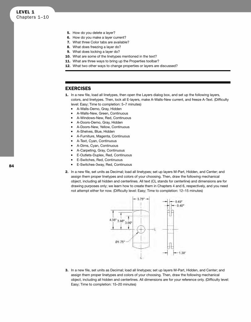
2. In a new fi le, set units as Decimal; load all linetypes; set up layers M-Part, Hidden, and Center; and assign them proper linetypes and colors of your choosing. Then, draw the following mechanical object, including all hidden and centerlines. All text (CL stands for centerline) and dimensions are for drawing purposes only; we learn how to create them in Chapters 4 and 6, respectively, and you need not attempt either for now. (Diffi culty level: Easy; Time to completion: 12–15 minutes )
3. In a new fi le, set units as Decimal; load all linetypes; set up layers M-Part, Hidden, and Center; and
assign them proper linetypes and colors of your choosing. Then, draw the following mechanical object, including all hidden and centerlines. All dimensions are for your reference only. (Diffi culty level: Easy; Time to completion: 15–20 minutes )
CH003.indd 84CH003.indd 84 6/29/2011 10:05:23 AM6/29/2011 10:05:23 AM

CHAPTER 3 Layers, Colors, Linetypes, and Properties
85
4. In a new fi le, set units as Decimal; load all linetypes; set up layers M-Part, Hidden, and Center; and assign them proper linetypes and colors of your choosing. Then, draw the following mechanical object, including all hidden and centerlines. All dimensions are for your reference only. (Diffi culty level: Intermediate; Time to completion: 20–25 minutes )
5. Often, in design work, you need to draw standard parts, because no CAD fi les are available. Such is the case with the following electrical termination blocks, breakers, and thermostat equipment. You are provided minimal dimensions, and your job is not to design the part but simply to document its appearance so an engineer can insert it into a larger modular design. In a new fi le, leave units as Decimal and set up layer E-Part, assigning it any color you wish. Then draw the electrical hardware, sizing everything relative to the overall provided dimensions and estimating most of the internal geometry. This is an excellent exercise in basic shape drafting. Be sure to use the copy command wisely to avoid signifi cant duplication of drawing effort. (Diffi culty level: Intermediate; Time to completion: 45 minutes )
CH003.indd 85CH003.indd 85 6/29/2011 10:05:23 AM6/29/2011 10:05:23 AM

LEVEL 1 Chapters 1–10
86
6. In a new fi le, set up Architectural units, the correct layers (only A-Walls and A-Doors are needed),
and draw the following fl oor plan. Dimensions, text, and the solid hatch pattern are for clarity and construction purposes only. We learn them in upcoming chapters. (Diffi culty level: Intermediate; Time to completion: 30–45 minutes )
CH003.indd 86CH003.indd 86 6/29/2011 10:05:24 AM6/29/2011 10:05:24 AM