Layer 2—LAN Switching Configuration Guide
347
H3C S6800 Switch Series Layer 2—LAN Switching Configuration Guide New H3C Technologies Co., Ltd. http://www.h3c.com Software version: Release 243x Document version: 6W101-20190125
Transcript of Layer 2—LAN Switching Configuration Guide
H3C S6800 Switch SeriesLayer 2—LAN Switching Configuration Guide
New H3C Technologies Co., Ltd. http://www.h3c.com Software version: Release 243x Document version: 6W101-20190125

Copyright © 2019, New H3C Technologies Co., Ltd. and its licensors
All rights reserved
No part of this manual may be reproduced or transmitted in any form or by any means without prior written consent of New H3C Technologies Co., Ltd.
Trademarks
Except for the trademarks of New H3C Technologies Co., Ltd., any trademarks that may be mentioned in this document are the property of their respective owners.
Notice
The information in this document is subject to change without notice. All contents in this document, including statements, information, and recommendations, are believed to be accurate, but they are presented without warranty of any kind, express or implied. H3C shall not be liable for technical or editorial errors or omissions contained herein.
Preface This configuration guide describes the Layer 2—LAN switching fundamentals and configuration procedures. It covers the following items: • Flow control and load sharing. • Isolating users within a VLAN and configuring VLANs. • Eliminating Layer 2 loops. • Transmitting packets of the customer network over the service provider network. • Modifying VLAN tags of packets.
This preface includes the following topics about the documentation: • Audience. • Conventions. • Documentation feedback.
Audience This documentation is intended for: • Network planners. • Field technical support and servicing engineers. • Network administrators working with the S6800 switch series.
Conventions The following information describes the conventions used in the documentation.
Command conventions
Convention Description Boldface Bold text represents commands and keywords that you enter literally as shown.
Italic Italic text represents arguments that you replace with actual values.
[ ] Square brackets enclose syntax choices (keywords or arguments) that are optional.
{ x | y | ... } Braces enclose a set of required syntax choices separated by vertical bars, from which you select one.
[ x | y | ... ] Square brackets enclose a set of optional syntax choices separated by vertical bars, from which you select one or none.
{ x | y | ... } * Asterisk marked braces enclose a set of required syntax choices separated by vertical bars, from which you select a minimum of one.
[ x | y | ... ] * Asterisk marked square brackets enclose optional syntax choices separated by vertical bars, from which you select one choice, multiple choices, or none.
&<1-n> The argument or keyword and argument combination before the ampersand (&) sign can be entered 1 to n times.
# A line that starts with a pound (#) sign is comments.
GUI conventions
Convention Description
Boldface Window names, button names, field names, and menu items are in Boldface. For example, the New User window opens; click OK.
> Multi-level menus are separated by angle brackets. For example, File > Create > Folder.
Symbols
Convention Description
WARNING! An alert that calls attention to important information that if not understood or followed can result in personal injury.
CAUTION: An alert that calls attention to important information that if not understood or followed can result in data loss, data corruption, or damage to hardware or software.
IMPORTANT: An alert that calls attention to essential information.
NOTE: An alert that contains additional or supplementary information.
TIP: An alert that provides helpful information.
Network topology icons
Convention Description
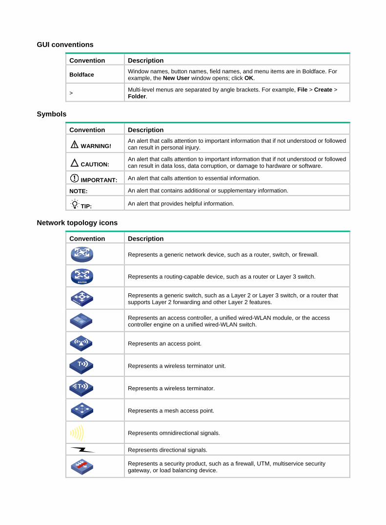
Represents a generic network device, such as a router, switch, or firewall.
Represents a routing-capable device, such as a router or Layer 3 switch.
Represents a generic switch, such as a Layer 2 or Layer 3 switch, or a router that supports Layer 2 forwarding and other Layer 2 features.
Represents an access controller, a unified wired-WLAN module, or the access controller engine on a unified wired-WLAN switch.
Represents an access point.
Represents a wireless terminator unit.
Represents a wireless terminator.
Represents a mesh access point.
Represents omnidirectional signals.
Represents directional signals.
Represents a security product, such as a firewall, UTM, multiservice security gateway, or load balancing device.
TT
TT
Convention Description
Represents a security module, such as a firewall, load balancing, NetStream, SSL VPN, IPS, or ACG module.
Examples provided in this document Examples in this document might use devices that differ from your device in hardware model, configuration, or software version. It is normal that the port numbers, sample output, screenshots, and other information in the examples differ from what you have on your device.
Documentation feedback You can e-mail your comments about product documentation to [email protected].
We appreciate your comments.

i
Contents
Configuring Ethernet interfaces ······································································ 1
Configuring a management Ethernet interface ·································································································· 1 Ethernet interface naming conventions ·············································································································· 1 Configuring common Ethernet interface settings ······························································································· 1
Splitting a 40-GE interface and combining 10-GE breakout interfaces ······················································ 2 Configuring basic settings of an Ethernet interface ···················································································· 3 Configuring the link mode of an Ethernet interface ···················································································· 4 Configuring jumbo frame support ··············································································································· 4 Configuring physical state change suppression on an Ethernet interface ················································· 5 Performing a loopback test on an Ethernet interface ················································································· 6 Configuring generic flow control on an Ethernet interface ········································································· 6 Configuring PFC on an Ethernet interface ································································································· 7 Enabling energy saving features on an Ethernet interface ········································································ 8 Setting the statistics polling interval ··········································································································· 9 Forcibly bringing up a fiber port ·················································································································· 9 Configuring storm suppression ················································································································ 10
Configuring a Layer 2 Ethernet interface ········································································································· 11 Configuring storm control on an Ethernet interface ·················································································· 11 Setting the MDIX mode of an Ethernet interface ······················································································ 13 Testing the cable connection of an Ethernet interface ············································································· 13 Enabling bridging on an Ethernet interface ······························································································ 14 Setting the interface connection distance ································································································ 14
Configuring a Layer 3 Ethernet interface or subinterface ················································································ 14 Setting the MTU for an Ethernet interface or subinterface ······································································· 14 Setting the MAC address for an Ethernet interface or subinterface ························································· 15
Displaying and maintaining an Ethernet interface ···························································································· 15 Configuring loopback, null, and inloopback interfaces ·································· 17
Configuring a loopback interface ····················································································································· 17 Configuring a null interface ······························································································································ 17 Configuring an inloopback interface ················································································································· 18 Displaying and maintaining loopback, null, and inloopback interfaces ···························································· 18
Bulk configuring interfaces ············································································ 19
Configuration restrictions and guidelines ········································································································· 19 Configuration procedure ·································································································································· 19 Displaying and maintaining bulk interface configuration ·················································································· 20
Configuring the MAC address table ······························································ 21
Overview ·························································································································································· 21 How a MAC address entry is created ······································································································· 21 Types of MAC address entries ················································································································· 21
MAC address table configuration task list ········································································································ 22 Configuring MAC address entries ···················································································································· 23
Configuration guidelines ··························································································································· 23 Adding or modifying a static or dynamic MAC address entry globally ····················································· 23 Adding or modifying a static or dynamic MAC address entry on an interface ·········································· 23 Adding or modifying a blackhole MAC address entry ·············································································· 24 Adding or modifying a multiport unicast MAC address entry ··································································· 24
Disabling MAC address learning ······················································································································ 26 Disabling global MAC address learning ··································································································· 26 Disabling MAC address learning on an interface ····················································································· 26 Disabling MAC address learning on a VLAN ··························································································· 27
Setting the aging timer for dynamic MAC address entries ··············································································· 27 Setting the MAC learning limit on an interface ································································································· 28 Configuring the device to forward unknown frames after the MAC learning limit on an interface is reached ·· 28 Assigning MAC learning priority to an interface ······························································································· 28

ii
Enabling MAC address synchronization ·········································································································· 29 Enable MAC address move notifications ········································································································· 31 Enabling ARP fast update for MAC address moves ························································································ 32 Disabling static source check ··························································································································· 33 Enabling SNMP notifications for the MAC address table ················································································· 33 Displaying and maintaining the MAC address table ························································································ 34 MAC address table configuration example ······································································································ 35
Network requirements ······························································································································ 35 Configuration procedure ··························································································································· 35 Verifying the configuration ························································································································ 35
Configuring MAC Information ········································································ 36
Enabling MAC Information ······························································································································· 36 Setting the MAC Information mode ·················································································································· 37 Setting the MAC change notification interval ··································································································· 37 Setting the MAC Information queue length ······································································································ 37 MAC Information configuration example ·········································································································· 37
Network requirements ······························································································································ 37 Configuration restrictions and guidelines ································································································· 38 Configuration procedure ··························································································································· 38
Configuring Ethernet link aggregation ··························································· 40
Basic concepts ················································································································································· 40 Aggregation group, member port, and aggregate interface ····································································· 40 Aggregation states of member ports in an aggregation group ································································· 41 Operational key ········································································································································ 41 Configuration types ·································································································································· 41 Link aggregation modes ··························································································································· 42
Aggregating links in static mode ······················································································································ 42 Choosing a reference port ························································································································ 42 Setting the aggregation state of each member port ················································································· 43
Aggregating links in dynamic mode ················································································································· 43 LACP ························································································································································ 44 How dynamic link aggregation works ······································································································· 45
Edge aggregate interface ································································································································· 47 Load sharing modes for link aggregation groups ····························································································· 47 Ethernet link aggregation configuration task list ······························································································ 47 Configuring an aggregation group ··················································································································· 48
Configuration restrictions and guidelines ································································································· 48 Configuring a Layer 2 aggregation group ································································································· 49 Configuring a Layer 3 aggregation group ································································································· 50 Configuring an S-channel bundle group ··································································································· 52
Configuring an aggregate interface ·················································································································· 53 Configuring the description of an aggregate interface ············································································· 53 Specifying ignored VLANs for a Layer 2 aggregate interface ·································································· 53 Setting the MTU for a Layer 3 aggregate interface ·················································································· 54 Setting the MAC address for a Layer 3 aggregate interface ···································································· 54 Setting the minimum and maximum numbers of Selected ports for an aggregation group ····················· 55 Setting the expected bandwidth for an aggregate interface ····································································· 56 Configuring an edge aggregate interface ································································································· 56 Enabling BFD for an aggregation group ··································································································· 57 Shutting down an aggregate interface ····································································································· 57 Restoring the default settings for an aggregate interface ········································································ 58
Configuring load sharing for link aggregation groups ······················································································ 58 Setting load sharing modes for link aggregation groups ·········································································· 58 Configuring the ignored fields for the default load sharing mode ····························································· 59 Enabling local-first load sharing for link aggregation ················································································ 59 Configuring per-flow load sharing algorithm settings for Ethernet link aggregation ································· 60 Setting the global load sharing mode for MAC-in-MAC traffic ·································································· 61
Enabling link-aggregation traffic redirection ····································································································· 61 Configuration restrictions and guidelines ································································································· 61 Configuration procedure ··························································································································· 62
iii
Specifying link aggregation management VLANs and management port ················································ 62 Specifying a link aggregation management subnet ························································································· 63 Displaying and maintaining Ethernet link aggregation ····················································································· 63 Ethernet link aggregation configuration examples ··························································································· 64
Layer 2 static aggregation configuration example ···················································································· 64 Layer 2 dynamic aggregation configuration example ··············································································· 66 Layer 2 aggregation load sharing configuration example ········································································ 68 Layer 2 edge aggregate interface configuration example ········································································ 70 Layer 3 static aggregation configuration example ···················································································· 72 Layer 3 dynamic aggregation configuration example ··············································································· 73 Layer 3 edge aggregate interface configuration example ········································································ 74
Configuring port isolation ·············································································· 76
Assigning a port to an isolation group ·············································································································· 76 Displaying and maintaining port isolation ········································································································· 76 Port isolation configuration example ················································································································ 77
Network requirements ······························································································································ 77 Configuration procedure ··························································································································· 77 Verifying the configuration ························································································································ 77
Configuring spanning tree protocols ····························································· 79
STP ·································································································································································· 79 STP protocol packets ······························································································································· 79 Basic concepts in STP ····························································································································· 80 Calculation process of the STP algorithm ································································································ 81
RSTP ······························································································································································· 86 PVST ································································································································································ 87 MSTP ······························································································································································· 87
MSTP features ········································································································································· 87 MSTP basic concepts ······························································································································ 88 How MSTP works ····································································································································· 91 MSTP implementation on devices ············································································································ 92
Protocols and standards ·································································································································· 92 Spanning tree configuration task lists ·············································································································· 92
STP configuration task list ························································································································ 93 RSTP configuration task list ····················································································································· 94 PVST configuration task list ····················································································································· 95 MSTP configuration task list ····················································································································· 96
Setting the spanning tree mode ······················································································································· 96 Configuring an MST region ······························································································································ 97 Configuring the root bridge or a secondary root bridge ··················································································· 98
Configuring the current device as the root bridge of a specific spanning tree ········································· 98 Configuring the current device as a secondary root bridge of a specific spanning tree ··························· 99
Configuring the device priority ························································································································· 99 Configuring the maximum hops of an MST region ··························································································· 99 Configuring the network diameter of a switched network ·············································································· 100 Setting spanning tree timers ·························································································································· 100
Configuration restrictions and guidelines ······························································································· 101 Configuration procedure ························································································································· 101
Setting the timeout factor ······························································································································· 102 Setting the BPDU transmission rate ·············································································································· 102 Configuring edge ports ··································································································································· 103
Configuration restrictions and guidelines ······························································································· 103 Configuration procedure ························································································································· 103
Configuring path costs of ports ······················································································································ 103 Specifying a standard for the device to use when it calculates the default path cost ···························· 104 Configuring path costs of ports ·············································································································· 106 Configuration example ··························································································································· 106
Configuring the port priority ···························································································································· 107 Configuring the port link type ························································································································· 107
Configuration restrictions and guidelines ······························································································· 108 Configuration procedure ························································································································· 108
iv
Configuring the mode a port uses to recognize and send MSTP packets ····················································· 108 Enabling outputting port state transition information ······················································································ 109 Enabling the spanning tree feature ················································································································ 109
Enabling the spanning tree feature in STP/RSTP/MSTP mode ····························································· 109 Enabling the spanning tree feature in PVST mode ················································································ 110
Performing mCheck ······································································································································· 110 Configuration restrictions and guidelines ······························································································· 110 Configuration procedure ························································································································· 111
Configuring Digest Snooping ························································································································· 111 Configuration restrictions and guidelines ······························································································· 111 Configuration procedure ························································································································· 112 Digest Snooping configuration example································································································· 112
Configuring No Agreement Check ················································································································· 113 Configuration prerequisites ···················································································································· 114 Configuration procedure ························································································································· 115 No Agreement Check configuration example ························································································· 115
Configuring TC Snooping ······························································································································· 115 Configuration restrictions and guidelines ······························································································· 116 Configuration procedure ························································································································· 116
Configuring protection features ······················································································································ 116 Enabling BPDU guard ···························································································································· 117 Enabling root guard ································································································································ 118 Enabling loop guard ······························································································································· 118 Configuring port role restriction ·············································································································· 119 Configuring TC-BPDU transmission restriction ······················································································ 119 Enabling TC-BPDU guard ······················································································································ 120 Enabling BPDU drop ······························································································································ 120 Enabling dispute guard ·························································································································· 121
Disabling the device to reactivate the shutdown edge ports ·········································································· 122 Enabling BPDU transparent transmission on a port ······················································································ 122 Enabling SNMP notifications for new-root election and topology change events ·········································· 122 Displaying and maintaining the spanning tree ······························································································· 123 Spanning tree configuration example ············································································································ 124
MSTP configuration example ················································································································· 124 PVST configuration example ·················································································································· 127
Configuring L2PT ························································································ 131
Overview ························································································································································ 131 Background ············································································································································ 131 L2PT operating mechanism ··················································································································· 132
L2PT configuration task list ···························································································································· 133 Enabling L2PT ··············································································································································· 133 Setting the destination multicast MAC address for tunneled packets ···························································· 134 Displaying and maintaining L2PT ·················································································································· 134 L2PT configuration examples ························································································································ 135
Configuring L2PT for STP ······················································································································ 135 Configuring L2PT for LACP ···················································································································· 136
Configuring loop detection ·········································································· 140
Overview ························································································································································ 140 Loop detection mechanism ···················································································································· 140 Loop detection interval ··························································································································· 141 Loop protection actions ·························································································································· 141 Port status auto recovery ······················································································································· 141
Loop detection configuration task list ············································································································· 142 Enabling loop detection ·································································································································· 142
Enabling loop detection globally············································································································· 142 Enabling loop detection on a port··········································································································· 142
Setting the loop protection action ··················································································································· 143 Setting the global loop protection action ································································································ 143 Setting the loop protection action on a Layer 2 Ethernet interface or S-channel interface ···················· 143
v
Setting the loop protection action on a Layer 2 aggregate interface, S-channel aggregate interface, or S-channel bundle interface ···················································································································· 143
Setting the loop detection interval ·················································································································· 144 Displaying and maintaining loop detection ····································································································· 144 Loop detection configuration example ··········································································································· 144
Network requirements ···························································································································· 144 Configuration procedure ························································································································· 145 Verifying the configuration ······················································································································ 146
Configuring VLANs ····················································································· 148
Overview ························································································································································ 148 VLAN frame encapsulation ···················································································································· 148 Protocols and standards ························································································································ 149
Configuring basic VLAN settings ··················································································································· 149 Configuring basic settings of a VLAN interface ······························································································ 150 Configuring port-based VLANs ······················································································································ 151
Introduction ············································································································································ 151 Assigning an access port to a VLAN ······································································································ 152 Assigning a trunk port to a VLAN ··········································································································· 153 Assigning a hybrid port to a VLAN ········································································································· 154
Configuring MAC-based VLANs ···················································································································· 155 Introduction ············································································································································ 155 Configuration restrictions and guidelines ······························································································· 158 Configuring static MAC-based VLAN assignment ·················································································· 158 Configuring dynamic MAC-based VLAN assignment ············································································· 159 Configuring server-assigned MAC-based VLAN ···················································································· 159
Configuring IP subnet-based VLANs ············································································································· 160 Configuring protocol-based VLANs ················································································································ 161 Configuring a VLAN group ····························································································································· 162 Displaying and maintaining VLANs ················································································································ 162 VLAN configuration examples ························································································································ 163
Port-based VLAN configuration example ······························································································· 163 MAC-based VLAN configuration example ······························································································ 165 IP subnet-based VLAN configuration example ······················································································ 166 Protocol-based VLAN configuration example ························································································ 168
Configuring super VLANs ··········································································· 172
Super VLAN configuration task list ················································································································ 172 Creating a sub-VLAN ····································································································································· 172 Configuring a super VLAN ····························································································································· 172 Configuring a super VLAN interface ·············································································································· 173 Displaying and maintaining super VLANs ······································································································ 173 Super VLAN configuration example ··············································································································· 174
Network requirements ···························································································································· 174 Configuration procedure ························································································································· 174 Verifying the configuration ······················································································································ 175
Configuring the private VLAN ····································································· 177
Configuration task list ····································································································································· 177 Configuration restrictions and guidelines ······································································································· 178 Configuration procedure ································································································································ 178 Displaying and maintaining the private VLAN ································································································ 180 Private VLAN configuration examples ··········································································································· 180
Promiscuous port configuration example ······························································································· 180 Trunk promiscuous port configuration example ····················································································· 183 Trunk promiscuous and trunk secondary port configuration example ···················································· 186 Secondary VLAN Layer 3 communication configuration example ························································· 190
Configuring voice VLANs ············································································ 193
Overview ························································································································································ 193 Methods of identifying IP phones ··················································································································· 193
Identifying IP phones through OUI addresses ······················································································· 193
vi
Automatically identifying IP phones through LLDP ················································································ 194 Advertising the voice VLAN information to IP phones ··················································································· 194 IP phone access methods ······························································································································ 195
Connecting the host and the IP phone in series ···················································································· 195 Connecting the IP phone to the device ·································································································· 195
Configuring a voice VLAN on a port ··············································································································· 195 Voice VLAN assignment modes ············································································································· 195 Security mode and normal mode of voice VLANs ·················································································· 197 Configuration prerequisites ···················································································································· 198 Configuring the QoS priority settings for voice traffic ············································································· 198 Configuring a port to operate in automatic voice VLAN assignment mode ············································ 199 Configuring a port to operate in manual voice VLAN assignment mode ················································ 200
Enabling LLDP for automatic IP phone discovery ·························································································· 201 Configuration prerequisites ···················································································································· 201 Configuration restrictions and guidelines ······························································································· 201 Configuration procedure ························································································································· 201
Configuring LLDP or CDP to advertise a voice VLAN ··················································································· 201 Dynamically advertising an authorization VLAN through LLDP or CDP ························································ 202 Displaying and maintaining voice VLANs ······································································································ 202 Voice VLAN configuration examples ·············································································································· 203
Automatic voice VLAN assignment mode configuration example ·························································· 203 Manual voice VLAN assignment mode configuration example ······························································ 204
Configuring MVRP ······················································································ 207
MRP ······························································································································································· 207 MRP implementation ······························································································································ 207 MRP messages ······································································································································ 207 MRP timers ············································································································································ 209
MVRP registration modes ······························································································································ 210 Protocols and standards ································································································································ 210 MVRP configuration task list ·························································································································· 210 Configuration restrictions and guidelines ······································································································· 210 Configuration prerequisites ···························································································································· 211 Enabling MVRP ·············································································································································· 211 Setting an MVRP registration mode ··············································································································· 212 Setting MRP timers ········································································································································ 212 Enabling GVRP compatibility ························································································································· 213 Displaying and maintaining MVRP ················································································································· 213 MVRP configuration example ························································································································ 213
Network requirements ···························································································································· 213 Configuration procedure ························································································································· 214 Verifying the configuration ······················································································································ 217
Configuring QinQ ························································································ 224
Overview ························································································································································ 224 How QinQ works ···································································································································· 224 QinQ implementations ···························································································································· 225 Protocols and standards ························································································································ 225
Restrictions and guidelines ···························································································································· 226 Enabling QinQ ················································································································································ 226 Configuring transparent transmission for VLANs ··························································································· 226 Configuring the TPID in VLAN tags ··············································································································· 227
Configuring the CVLAN TPID ················································································································· 228 Configuring the SVLAN TPID ················································································································· 228
Setting the 802.1p priority in SVLAN tags ······································································································ 228 Displaying and maintaining QinQ ··················································································································· 229 QinQ configuration examples ························································································································· 230
Basic QinQ configuration example ········································································································· 230 VLAN transparent transmission configuration example ········································································· 232
Configuring VLAN mapping ········································································ 234
Overview ························································································································································ 234
vii
Application scenario of one-to-one and many-to-one VLAN mapping ··················································· 234 Application scenario of one-to-two and two-to-two VLAN mapping ······················································· 236 VLAN mapping implementations ············································································································ 236
General configuration restrictions and guidelines ·························································································· 239 VLAN mapping configuration task list ············································································································ 239 Configuring one-to-one VLAN mapping ········································································································· 240 Configuring many-to-one VLAN mapping ······································································································ 240
Configuring many-to-one VLAN mapping in a network with dynamic IP address assignment ··············· 241 Configuring many-to-one VLAN mapping in a network with static IP address assignment ···················· 243
Configuring one-to-two VLAN mapping ········································································································· 245 Configuring two-to-two VLAN mapping ·········································································································· 245 Displaying and maintaining VLAN mapping ··································································································· 246 VLAN mapping configuration examples ········································································································· 246
One-to-one and many-to-one VLAN mapping configuration example ··················································· 246 One-to-two and two-to-two VLAN mapping configuration example ······················································· 250
Configuring PBB ························································································· 254
Overview ························································································································································ 254 PBB network model ································································································································ 254 Terminology ··········································································································································· 255 PBB frame format ··································································································································· 255 PBB frame forwarding ···························································································································· 257 Protocols and standards ························································································································ 257
PBB configuration task list ····························································································································· 257 Enabling L2VPN ············································································································································· 258 Creating a PBB VSI ······································································································································· 258 Configuring a B-VLAN for a PBB VSI ············································································································ 258 Configuring an uplink port ······························································································································ 258 Configuring a downlink port ··························································································································· 259 Configuring the data encapsulation type ········································································································ 260 Displaying and maintaining PBB ···················································································································· 261 PBB configuration example ···························································································································· 261
Network requirements ···························································································································· 261 Configuration procedures ······················································································································· 262 Verifying the configuration ······················································································································ 263
Troubleshooting ············································································································································· 263 Symptom ················································································································································ 263 Analysis ·················································································································································· 263 Solution ·················································································································································· 263
Configuring LLDP ························································································ 264
Overview ························································································································································ 264 Basic concepts ······································································································································· 264 Working mechanism ······························································································································· 269 Protocols and standards ························································································································ 270
LLDP configuration task list ··························································································································· 270 Performing basic LLDP configurations ··········································································································· 270
Enabling LLDP ······································································································································· 270 Configuring the LLDP bridge mode ········································································································ 271 Setting the LLDP operating mode ·········································································································· 272 Setting the LLDP reinitialization delay ···································································································· 272 Enabling LLDP polling ···························································································································· 273 Configuring the advertisable TLVs ········································································································· 273 Configuring the management address and its encoding format ····························································· 275 Setting other LLDP parameters ·············································································································· 276 Setting an encapsulation format for LLDP frames ················································································· 277 Disabling PVID inconsistency check ······································································································ 278
Configuring CDP compatibility ······················································································································· 278 Configuration prerequisites ···················································································································· 279 Configuration procedure ························································································································· 279
Configuring LLDP neighbor validation and aging ··························································································· 279 Configuring LLDP neighbor validation on an interface ··········································································· 279
viii
Configuring LLDP neighbor aging on an interface ················································································· 280 Configuring DCBX ·········································································································································· 280
DCBX configuration task list ··················································································································· 281 Enabling LLDP and DCBX TLV advertising ··························································································· 282 Configuring APP parameters ················································································································· 282 Configuring ETS parameters ·················································································································· 284 Configuring PFC parameters ················································································································· 285 Configuring the DCBX version ··············································································································· 286
Configuring LLDP trapping and LLDP-MED trapping ···················································································· 286 Displaying and maintaining LLDP ·················································································································· 287 LLDP configuration examples ························································································································ 288
Basic LLDP configuration example ········································································································ 288 CDP-compatible LLDP configuration example ······················································································· 292
DCBX configuration example ························································································································· 294 Configuring service loopback groups ·························································· 300
Configuration procedure ································································································································ 300 Displaying and maintaining service loopback groups ···················································································· 300 Service loopback group configuration example ····························································································· 301
Network requirements ···························································································································· 301 Configuration procedure ························································································································· 301
Configuring cut-through Layer 2 forwarding ················································ 302
Index ··········································································································· 303

1
Configuring Ethernet interfaces The switch series supports Ethernet interfaces, management Ethernet interfaces, Console interfaces, and USB interfaces. For the interface types and the number of interfaces supported by a switch model, see the installation guide.
This document describes how to configure management Ethernet interfaces and Ethernet interfaces.
Configuring a management Ethernet interface A management interface uses an RJ-45 connector. You can connect the interface to a PC for software loading and system debugging, or connect it to a remote NMS for remote system management.
To configure a management Ethernet interface:
Step Command Remarks 1. Enter system view. system-view N/A
2. Enter management Ethernet interface view.
interface M-GigabitEthernet interface-number
N/A
3. (Optional.) Set the interface description. description text The default setting is
M-GigabitEthernet0/0/0 Interface.
4. (Optional.) Shut down the interface. shutdown By default, the management Ethernet
interface is up.
Ethernet interface naming conventions The Ethernet interfaces are named in the format of interface type A/B/C. The letters that follow the interface type represent the following elements: • A—IRF member ID. If the switch is not in an IRF fabric, A is 1 by default. • B—Card slot number. 0 indicates the interface is a fixed interface of the switch. 1 indicates the
interface is on expansion interface-card 1. 2 indicates the interface is on expansion interface-card 2.
• C—Port index.
A 10-GE breakout interface split from a 40-GE interface is named in the format of interface type A/B/C:D. A/B/C is the interface number of the 40-GE interface and D is the number of the 10-GE interface, which is in the range of 1 to 4. For information about splitting a 40-GE interface, see "Splitting a 40-GE interface and combining 10-GE breakout interfaces."
Configuring common Ethernet interface settings This section describes the settings common to Layer 2 and Layer 3 Ethernet interfaces. You can set an Ethernet interface as a Layer 3 interface by using the port link-mode route command. For more information, see "Configuring the link mode of an Ethernet interface." For more information about the settings specific to Layer 2 and Layer 3 Ethernet interfaces, see "Configuring a Layer 2 Ethernet interface" and "Configuring a Layer 3 Ethernet interface or subinterface."
2
Splitting a 40-GE interface and combining 10-GE breakout interfaces
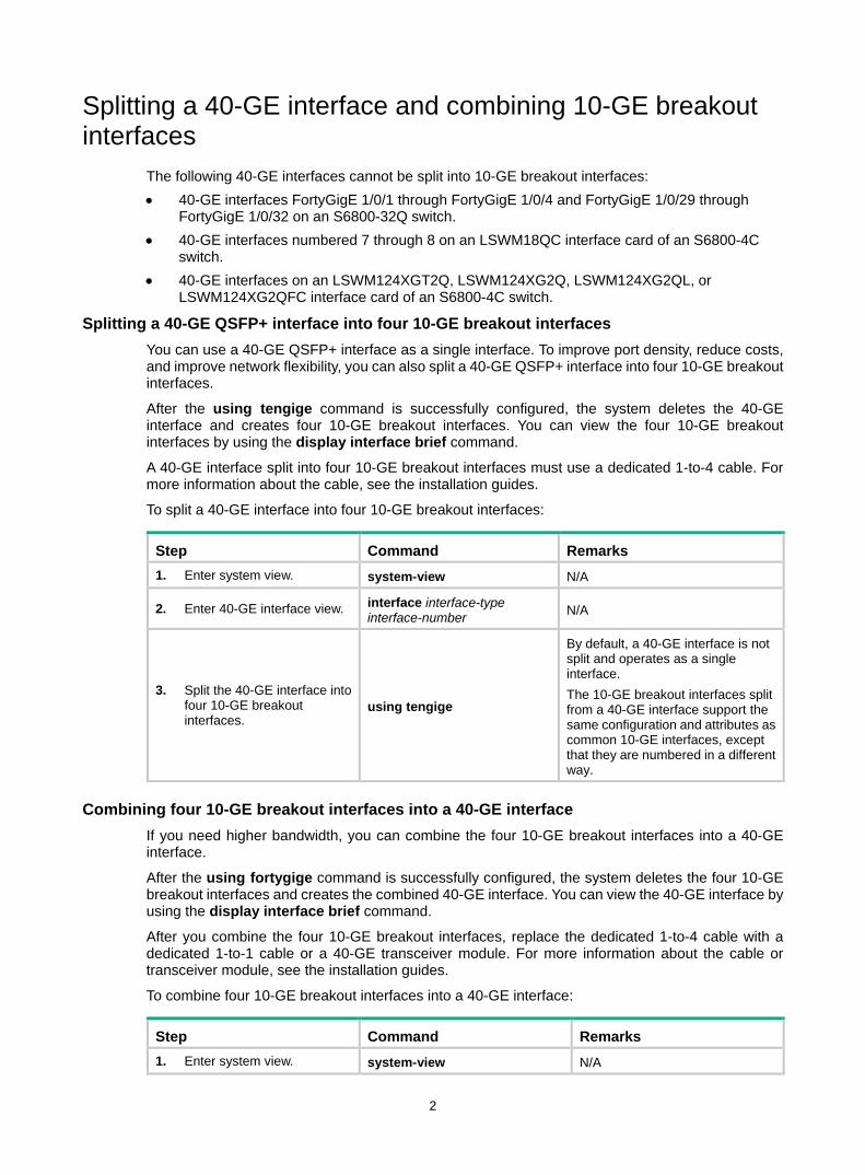
The following 40-GE interfaces cannot be split into 10-GE breakout interfaces: • 40-GE interfaces FortyGigE 1/0/1 through FortyGigE 1/0/4 and FortyGigE 1/0/29 through
FortyGigE 1/0/32 on an S6800-32Q switch. • 40-GE interfaces numbered 7 through 8 on an LSWM18QC interface card of an S6800-4C
switch. • 40-GE interfaces on an LSWM124XGT2Q, LSWM124XG2Q, LSWM124XG2QL, or
LSWM124XG2QFC interface card of an S6800-4C switch.
Splitting a 40-GE QSFP+ interface into four 10-GE breakout interfaces You can use a 40-GE QSFP+ interface as a single interface. To improve port density, reduce costs, and improve network flexibility, you can also split a 40-GE QSFP+ interface into four 10-GE breakout interfaces.
After the using tengige command is successfully configured, the system deletes the 40-GE interface and creates four 10-GE breakout interfaces. You can view the four 10-GE breakout interfaces by using the display interface brief command.
A 40-GE interface split into four 10-GE breakout interfaces must use a dedicated 1-to-4 cable. For more information about the cable, see the installation guides.
To split a 40-GE interface into four 10-GE breakout interfaces:
Step Command Remarks 1. Enter system view. system-view N/A
2. Enter 40-GE interface view. interface interface-type interface-number N/A
3. Split the 40-GE interface into four 10-GE breakout interfaces.
using tengige
By default, a 40-GE interface is not split and operates as a single interface. The 10-GE breakout interfaces split from a 40-GE interface support the same configuration and attributes as common 10-GE interfaces, except that they are numbered in a different way.
Combining four 10-GE breakout interfaces into a 40-GE interface If you need higher bandwidth, you can combine the four 10-GE breakout interfaces into a 40-GE interface.
After the using fortygige command is successfully configured, the system deletes the four 10-GE breakout interfaces and creates the combined 40-GE interface. You can view the 40-GE interface by using the display interface brief command.
After you combine the four 10-GE breakout interfaces, replace the dedicated 1-to-4 cable with a dedicated 1-to-1 cable or a 40-GE transceiver module. For more information about the cable or transceiver module, see the installation guides.
To combine four 10-GE breakout interfaces into a 40-GE interface:
Step Command Remarks 1. Enter system view. system-view N/A
3
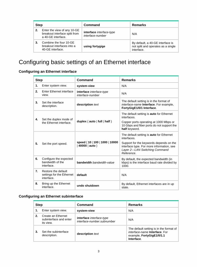
Step Command Remarks 2. Enter the view of any 10-GE
breakout interface split from a 40-GE interface.
interface interface-type interface-number N/A
3. Combine the four 10-GE breakout interfaces into a 40-GE interface.
using fortygige By default, a 40-GE interface is not split and operates as a single interface.
Configuring basic settings of an Ethernet interface Configuring an Ethernet interface
Step Command Remarks 1. Enter system view. system-view N/A
2. Enter Ethernet interface view.
interface interface-type interface-number N/A
3. Set the interface description. description text
The default setting is in the format of interface-name Interface. For example, FortyGigE1/0/1 Interface.
4. Set the duplex mode of the Ethernet interface. duplex { auto | full | half }
The default setting is auto for Ethernet interfaces. Copper ports operating at 1000 Mbps or 10 Gbps and fiber ports do not support the half keyword.
5. Set the port speed. speed { 10 | 100 | 1000 | 10000 | 40000 | auto }
The default setting is auto for Ethernet interfaces. Support for the keywords depends on the interface type. For more information, see Layer 2—LAN Switching Command Reference.
6. Configure the expected bandwidth of the interface.
bandwidth bandwidth-value By default, the expected bandwidth (in kbps) is the interface baud rate divided by 1000.
7. Restore the default settings for the Ethernet interface.
default N/A
8. Bring up the Ethernet interface. undo shutdown By default, Ethernet interfaces are in up
state.
Configuring an Ethernet subinterface
Step Command Remarks 1. Enter system view. system-view N/A
2. Create an Ethernet subinterface and enter its view.
interface interface-type interface-number.subnumber N/A
3. Set the subinterface description. description text
The default setting is in the format of interface-name Interface. For example, FortyGigE1/0/1.1 Interface.

4
Step Command Remarks 4. Restore the default
settings for the Ethernet subinterface.
default N/A
5. Configure the expected bandwidth for the interface.
bandwidth bandwidth-value By default, the expected bandwidth (in kbps) is the interface baud rate divided by 1000.
6. Bring up the Ethernet subinterface. undo shutdown By default, Ethernet subinterfaces
are in up state.
Configuring the link mode of an Ethernet interface
CAUTION: After you change the link mode of an Ethernet interface, all commands (except the shutdown command) on the Ethernet interface are restored to their defaults in the new link mode.
The interfaces on this switch series can operate either as Layer 2 or Layer 3 Ethernet interfaces.
You can set the link mode to bridge or route.
To change the link mode of an Ethernet interface:
Step Command Remarks 1. Enter system view. system-view N/A
2. Enter Ethernet interface view.
interface interface-type interface-number N/A
3. Change the link mode of the Ethernet interface. port link-mode { bridge | route } By default, Ethernet interfaces
operate in bridge mode.
Configuring jumbo frame support An Ethernet interface might receive some frames larger than the standard Ethernet frame size during high-throughput data exchanges, such as file transfers. These frames are called jumbo frames.
The interface processes jumbo frames in the following ways: • When the Ethernet interface is configured to deny jumbo frames (by using the undo
jumboframe enable command), the Ethernet interface discards jumbo frames without further processing.
• When the Ethernet interface is configured with jumbo frame support, the Ethernet interface performs the following operations: Processes jumbo frames within the specified length. Discards jumbo frames exceeding the specified length without further processing.
To configure jumbo frame support in interface view:
Step Command Remarks 1. Enter system view. system-view N/A
2. Enter Ethernet interface view.
interface interface-type interface-number N/A
5
Step Command Remarks
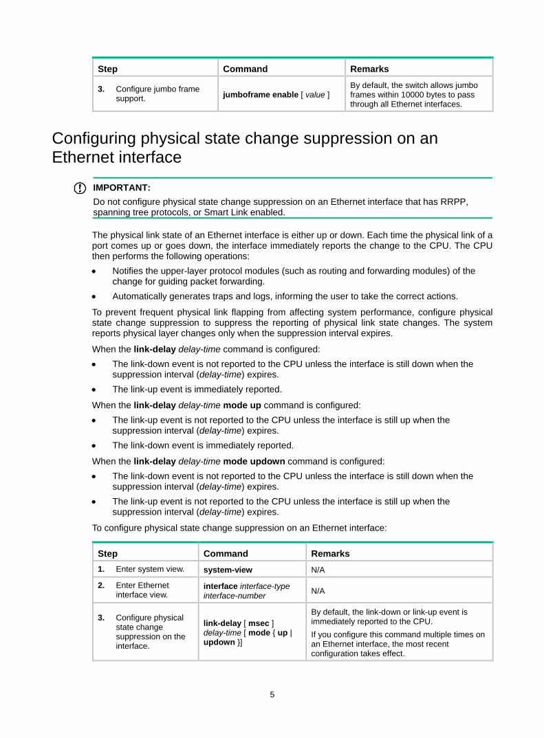
3. Configure jumbo frame support. jumboframe enable [ value ]
By default, the switch allows jumbo frames within 10000 bytes to pass through all Ethernet interfaces.
Configuring physical state change suppression on an Ethernet interface
IMPORTANT: Do not configure physical state change suppression on an Ethernet interface that has RRPP, spanning tree protocols, or Smart Link enabled.
The physical link state of an Ethernet interface is either up or down. Each time the physical link of a port comes up or goes down, the interface immediately reports the change to the CPU. The CPU then performs the following operations: • Notifies the upper-layer protocol modules (such as routing and forwarding modules) of the
change for guiding packet forwarding. • Automatically generates traps and logs, informing the user to take the correct actions.
To prevent frequent physical link flapping from affecting system performance, configure physical state change suppression to suppress the reporting of physical link state changes. The system reports physical layer changes only when the suppression interval expires.
When the link-delay delay-time command is configured: • The link-down event is not reported to the CPU unless the interface is still down when the
suppression interval (delay-time) expires. • The link-up event is immediately reported.
When the link-delay delay-time mode up command is configured: • The link-up event is not reported to the CPU unless the interface is still up when the
suppression interval (delay-time) expires. • The link-down event is immediately reported.
When the link-delay delay-time mode updown command is configured: • The link-down event is not reported to the CPU unless the interface is still down when the
suppression interval (delay-time) expires. • The link-up event is not reported to the CPU unless the interface is still up when the
suppression interval (delay-time) expires.
To configure physical state change suppression on an Ethernet interface:
Step Command Remarks 1. Enter system view. system-view N/A
2. Enter Ethernet interface view.
interface interface-type interface-number N/A
3. Configure physical state change suppression on the interface.
link-delay [ msec ] delay-time [ mode { up | updown }]
By default, the link-down or link-up event is immediately reported to the CPU. If you configure this command multiple times on an Ethernet interface, the most recent configuration takes effect.

6
Performing a loopback test on an Ethernet interface If an Ethernet interface does not work correctly, you can perform a loopback test on it to identify the problem. An Ethernet interface in a loopback test does not forward data traffic.
Loopback tests include the following types: • Internal loopback test—Tests all on-chip functions related to the Ethernet interface. • External loopback test—Tests the hardware of the Ethernet interface. To perform an external
loopback test on the Ethernet interface, connect a loopback plug to the Ethernet interface. The switch sends test packets out of the interface, which are expected to loop over the plug and back to the interface. If the interface fails to receive any test packets, the hardware of the interface is faulty.
Configuration restrictions and guidelines • On an administratively shut down Ethernet interface (displayed as in ADM or Administratively
DOWN state), you cannot perform an internal or external loopback test. • The speed, duplex, mdix-mode, and shutdown commands are not available during a
loopback test. • During a loopback test, the Ethernet interface operates in full duplex mode. When a loopback
test is complete, the port returns to its duplex setting.
Configuration procedure To perform a loopback test on an Ethernet interface:
Step Command Remarks 1. Enter system view. system-view N/A
2. Enter Ethernet interface view.
interface interface-type interface-number N/A
3. Perform a loopback test. loopback { external | internal } By default, no loopback test is performed.
Configuring generic flow control on an Ethernet interface
CAUTION: Configuring generic flow control on an Ethernet interface will cause link-up and link-down events before the interface finally stays up.
To avoid packet drops on a link, you can enable generic flow control at both ends of the link. When traffic congestion occurs at the receiving end, the receiving end sends a flow control (Pause) frame to ask the sending end to suspend sending packets. • With TxRx mode generic flow control enabled, an interface can both send and receive flow
control frames. When congestion occurs, the interface sends a flow control frame to its peer. When the interface receives a flow control frame from the peer, it suspends sending packets.
• With Rx flow mode generic control enabled, an interface can receive flow control frames, but it cannot send flow control frames. When the interface receives a flow control frame from its peer, it suspends sending packets to the peer. When congestion occurs, the interface cannot send flow control frames to the peer.
To handle unidirectional traffic congestion on a link, configure the flow-control receive enable command at one end and the flow-control command at the other end. To enable both ends of a link to handle traffic congestion, configure the flow-control command at both ends.
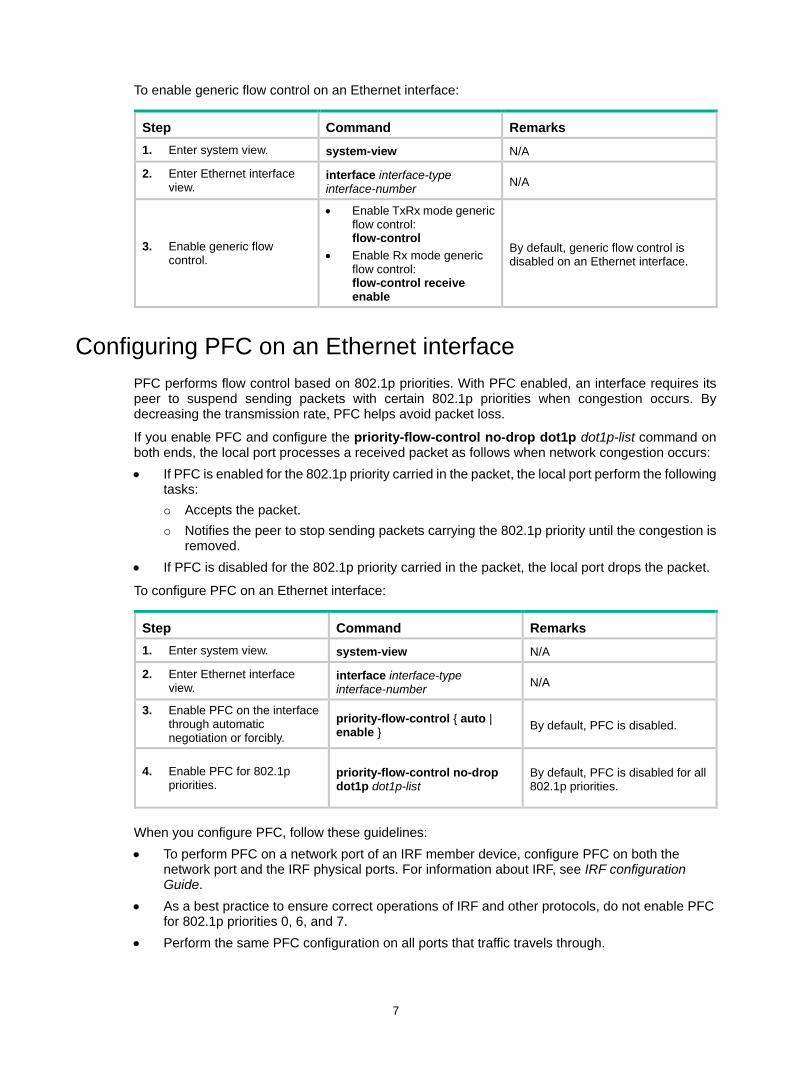
7
To enable generic flow control on an Ethernet interface:
Step Command Remarks 1. Enter system view. system-view N/A
2. Enter Ethernet interface view.
interface interface-type interface-number N/A
3. Enable generic flow control.
• Enable TxRx mode generic flow control: flow-control
• Enable Rx mode generic flow control: flow-control receive enable
By default, generic flow control is disabled on an Ethernet interface.
Configuring PFC on an Ethernet interface PFC performs flow control based on 802.1p priorities. With PFC enabled, an interface requires its peer to suspend sending packets with certain 802.1p priorities when congestion occurs. By decreasing the transmission rate, PFC helps avoid packet loss.
If you enable PFC and configure the priority-flow-control no-drop dot1p dot1p-list command on both ends, the local port processes a received packet as follows when network congestion occurs: • If PFC is enabled for the 802.1p priority carried in the packet, the local port perform the following
tasks: Accepts the packet. Notifies the peer to stop sending packets carrying the 802.1p priority until the congestion is
removed. • If PFC is disabled for the 802.1p priority carried in the packet, the local port drops the packet.
To configure PFC on an Ethernet interface:
Step Command Remarks 1. Enter system view. system-view N/A
2. Enter Ethernet interface view.
interface interface-type interface-number N/A
3. Enable PFC on the interface through automatic negotiation or forcibly.
priority-flow-control { auto | enable } By default, PFC is disabled.
4. Enable PFC for 802.1p priorities.
priority-flow-control no-drop dot1p dot1p-list
By default, PFC is disabled for all 802.1p priorities.
When you configure PFC, follow these guidelines: • To perform PFC on a network port of an IRF member device, configure PFC on both the
network port and the IRF physical ports. For information about IRF, see IRF configuration Guide.
• As a best practice to ensure correct operations of IRF and other protocols, do not enable PFC for 802.1p priorities 0, 6, and 7.
• Perform the same PFC configuration on all ports that traffic travels through.
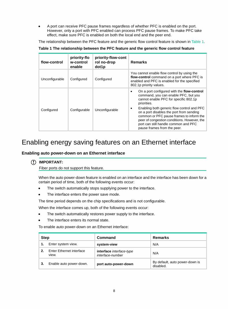
8
• A port can receive PFC pause frames regardless of whether PFC is enabled on the port. However, only a port with PFC enabled can process PFC pause frames. To make PFC take effect, make sure PFC is enabled on both the local end and the peer end.
The relationship between the PFC feature and the generic flow control feature is shown in Table 1.
Table 1 The relationship between the PFC feature and the generic flow control feature
flow-control priority-flow-control enable
priority-flow-control no-drop dot1p
Remarks
Unconfigurable Configured Configured
You cannot enable flow control by using the flow-control command on a port where PFC is enabled and PFC is enabled for the specified 802.1p priority values.
Configured Configurable Unconfigurable
• On a port configured with the flow-control command, you can enable PFC, but you cannot enable PFC for specific 802.1p priorities.
• Enabling both generic flow control and PFC on a port disables the port from sending common or PFC pause frames to inform the peer of congestion conditions. However, the port can still handle common and PFC pause frames from the peer.
Enabling energy saving features on an Ethernet interface Enabling auto power-down on an Ethernet interface
IMPORTANT: Fiber ports do not support this feature.
When the auto power-down feature is enabled on an interface and the interface has been down for a certain period of time, both of the following events occur: • The switch automatically stops supplying power to the interface. • The interface enters the power save mode.
The time period depends on the chip specifications and is not configurable.
When the interface comes up, both of the following events occur: • The switch automatically restores power supply to the interface. • The interface enters its normal state.
To enable auto power-down on an Ethernet interface:
Step Command Remarks 1. Enter system view. system-view N/A
2. Enter Ethernet interface view.
interface interface-type interface-number N/A
3. Enable auto power-down. port auto-power-down By default, auto power-down is disabled.
9
Enabling EEE energy saving for Ethernet interfaces in up state
IMPORTANT: Fiber ports do not support this feature.
With the Energy Efficient Ethernet (EEE) energy saving feature, a link-up port enters the low power state if it has not received any packet for a certain period of time. The time period depends on the chip specifications and is not configurable. When a packet arrives later, the switch automatically restores power supply to the interface and the port enters the normal state.
To enable EEE energy saving:
Step Command Remarks 1. Enter system view. system-view N/A
2. Enter Ethernet interface view.
interface interface-type interface-number N/A
3. Enable EEE energy saving. eee enable By default, EEE energy
saving is disabled.
Setting the statistics polling interval To set the statistics polling interval in Ethernet interface view:
Step Command Remarks 1. Enter system view. system-view N/A
2. Enter Ethernet interface view.
interface interface-type interface-number N/A
3. Set the statistics polling interval. flow-interval interval By default, the statistics polling
interval is 300 seconds.
To display the interface statistics collected in the last polling interval, use the display interface command.
To clear interface statistics, use the reset counters interface command.
Forcibly bringing up a fiber port
CAUTION: The following operations on a fiber port will cause link updown events before the port finally stays up: • Configure the port up-mode command and the speed or duplex command at the same time. • Install or remove fiber links or transceiver modules after you forcibly bring up the fiber port.
IMPORTANT: Copper ports do not support this feature.
As shown in Figure 1, a fiber port typically uses separate fibers for transmitting and receiving packets. The physical state of the fiber port is up only when both transmit and receive fibers are physically connected. If one of the fibers is disconnected, the fiber port does not work.
To enable a fiber port to forward traffic over a single link, you can use the port up-mode command. This command brings up a fiber port by force, even when no fiber links or optical modules are
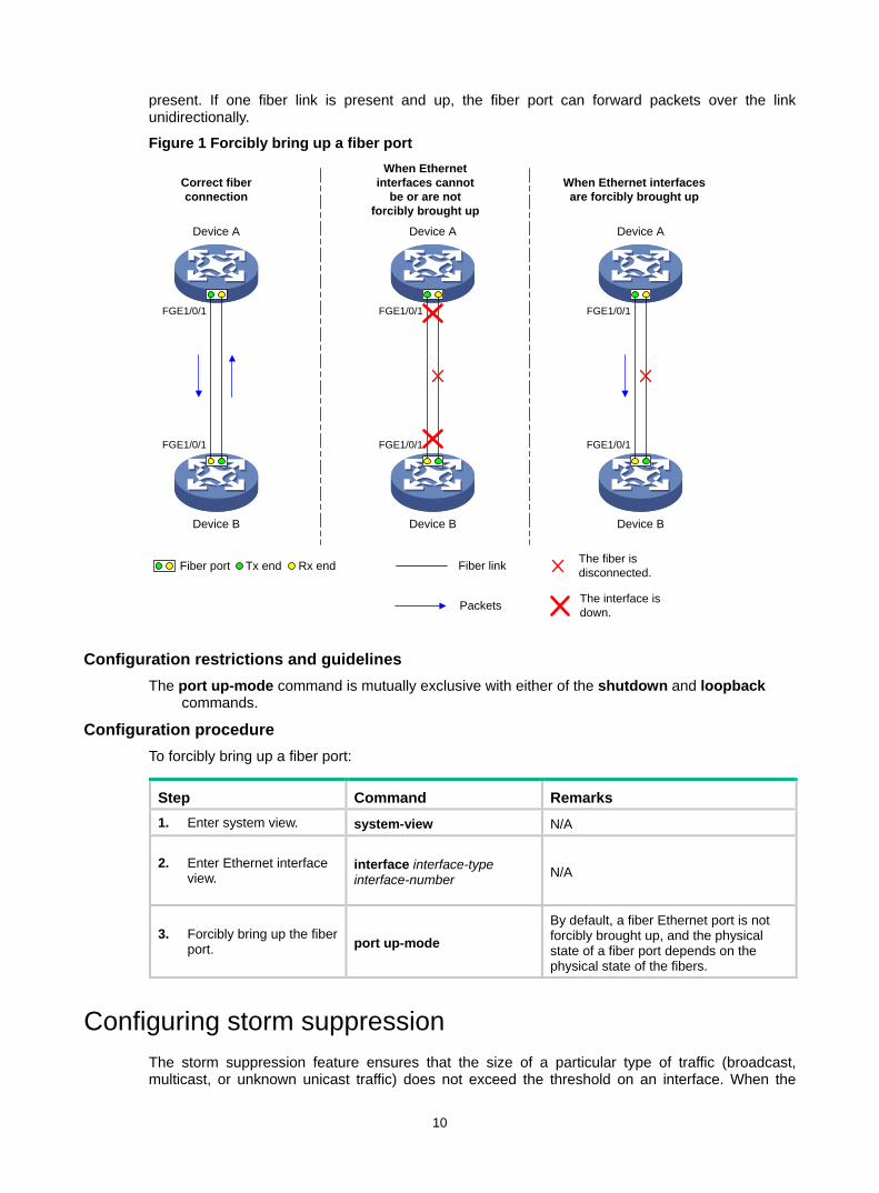
10
present. If one fiber link is present and up, the fiber port can forward packets over the link unidirectionally.
Figure 1 Forcibly bring up a fiber port
Configuration restrictions and guidelines The port up-mode command is mutually exclusive with either of the shutdown and loopback
commands.
Configuration procedure To forcibly bring up a fiber port:
Step Command Remarks 1. Enter system view. system-view N/A
2. Enter Ethernet interface view.
interface interface-type interface-number N/A
3. Forcibly bring up the fiber port. port up-mode
By default, a fiber Ethernet port is not forcibly brought up, and the physical state of a fiber port depends on the physical state of the fibers.
Configuring storm suppression The storm suppression feature ensures that the size of a particular type of traffic (broadcast, multicast, or unknown unicast traffic) does not exceed the threshold on an interface. When the
Correct fiber connection
When Ethernet interfaces cannot
be or are not forcibly brought up
When Ethernet interfaces are forcibly brought up
The fiber is disconnected.Fiber link
FGE1/0/1
FGE1/0/1
Device A
Device B
FGE1/0/1
FGE1/0/1
Device A
Device B
FGE1/0/1
FGE1/0/1
Device A
Device B
The interface is down.Packets
Fiber port Tx end Rx end
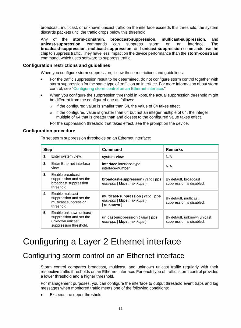
11
broadcast, multicast, or unknown unicast traffic on the interface exceeds this threshold, the system discards packets until the traffic drops below this threshold.
Any of the storm-constrain, broadcast-suppression, multicast-suppression, and unicast-suppression commands can suppress storm on an interface. The broadcast-suppression, multicast-suppression, and unicast-suppression commands use the chip to suppress traffic. They have less impact on the device performance than the storm-constrain command, which uses software to suppress traffic.
Configuration restrictions and guidelines When you configure storm suppression, follow these restrictions and guidelines: • For the traffic suppression result to be determined, do not configure storm control together with
storm suppression for the same type of traffic on an interface. For more information about storm control, see "Configuring storm control on an Ethernet interface."
• When you configure the suppression threshold in kbps, the actual suppression threshold might be different from the configured one as follows: If the configured value is smaller than 64, the value of 64 takes effect. If the configured value is greater than 64 but not an integer multiple of 64, the integer
multiple of 64 that is greater than and closest to the configured value takes effect. For the suppression threshold that takes effect, see the prompt on the device.
Configuration procedure To set storm suppression thresholds on an Ethernet interface:
Step Command Remarks 1. Enter system view. system-view N/A
2. Enter Ethernet interface view.
interface interface-type interface-number N/A
3. Enable broadcast suppression and set the broadcast suppression threshold.
broadcast-suppression { ratio | pps max-pps | kbps max-kbps }
By default, broadcast suppression is disabled.
4. Enable multicast suppression and set the multicast suppression threshold.
multicast-suppression { ratio | pps max-pps | kbps max-kbps } [ unknown ]
By default, multicast suppression is disabled.
5. Enable unknown unicast suppression and set the unknown unicast suppression threshold.
unicast-suppression { ratio | pps max-pps | kbps max-kbps }
By default, unknown unicast suppression is disabled.
Configuring a Layer 2 Ethernet interface Configuring storm control on an Ethernet interface
Storm control compares broadcast, multicast, and unknown unicast traffic regularly with their respective traffic thresholds on an Ethernet interface. For each type of traffic, storm control provides a lower threshold and a higher threshold.
For management purposes, you can configure the interface to output threshold event traps and log messages when monitored traffic meets one of the following conditions: • Exceeds the upper threshold.
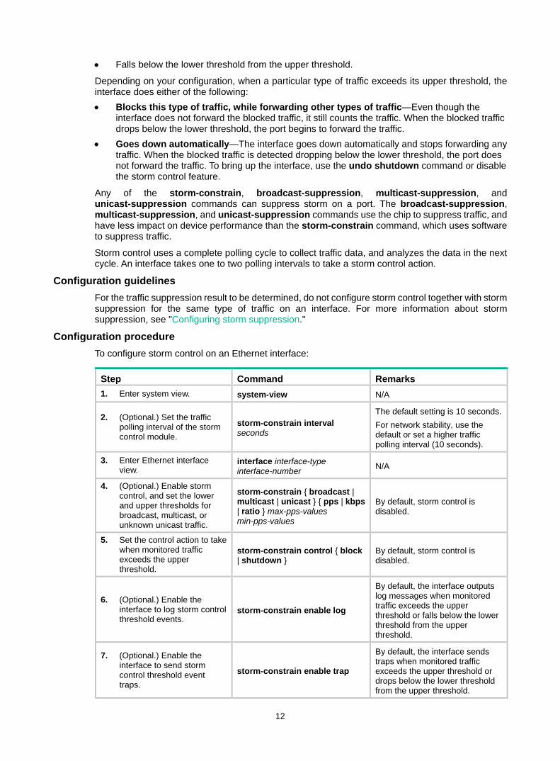
12
• Falls below the lower threshold from the upper threshold.
Depending on your configuration, when a particular type of traffic exceeds its upper threshold, the interface does either of the following: • Blocks this type of traffic, while forwarding other types of traffic—Even though the
interface does not forward the blocked traffic, it still counts the traffic. When the blocked traffic drops below the lower threshold, the port begins to forward the traffic.
• Goes down automatically—The interface goes down automatically and stops forwarding any traffic. When the blocked traffic is detected dropping below the lower threshold, the port does not forward the traffic. To bring up the interface, use the undo shutdown command or disable the storm control feature.
Any of the storm-constrain, broadcast-suppression, multicast-suppression, and unicast-suppression commands can suppress storm on a port. The broadcast-suppression, multicast-suppression, and unicast-suppression commands use the chip to suppress traffic, and have less impact on device performance than the storm-constrain command, which uses software to suppress traffic.
Storm control uses a complete polling cycle to collect traffic data, and analyzes the data in the next cycle. An interface takes one to two polling intervals to take a storm control action.
Configuration guidelines For the traffic suppression result to be determined, do not configure storm control together with storm suppression for the same type of traffic on an interface. For more information about storm suppression, see "Configuring storm suppression."
Configuration procedure To configure storm control on an Ethernet interface:
Step Command Remarks 1. Enter system view. system-view N/A
2. (Optional.) Set the traffic polling interval of the storm control module.
storm-constrain interval seconds
The default setting is 10 seconds. For network stability, use the default or set a higher traffic polling interval (10 seconds).
3. Enter Ethernet interface view.
interface interface-type interface-number N/A
4. (Optional.) Enable storm control, and set the lower and upper thresholds for broadcast, multicast, or unknown unicast traffic.
storm-constrain { broadcast | multicast | unicast } { pps | kbps | ratio } max-pps-values min-pps-values
By default, storm control is disabled.
5. Set the control action to take when monitored traffic exceeds the upper threshold.
storm-constrain control { block | shutdown }
By default, storm control is disabled.
6. (Optional.) Enable the interface to log storm control threshold events.
storm-constrain enable log
By default, the interface outputs log messages when monitored traffic exceeds the upper threshold or falls below the lower threshold from the upper threshold.
7. (Optional.) Enable the interface to send storm control threshold event traps.
storm-constrain enable trap
By default, the interface sends traps when monitored traffic exceeds the upper threshold or drops below the lower threshold from the upper threshold.
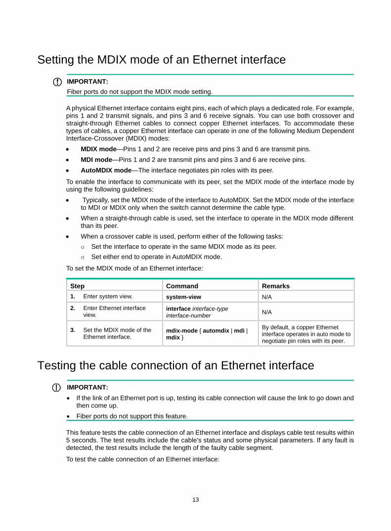
13
Setting the MDIX mode of an Ethernet interface
IMPORTANT: Fiber ports do not support the MDIX mode setting.
A physical Ethernet interface contains eight pins, each of which plays a dedicated role. For example, pins 1 and 2 transmit signals, and pins 3 and 6 receive signals. You can use both crossover and straight-through Ethernet cables to connect copper Ethernet interfaces. To accommodate these types of cables, a copper Ethernet interface can operate in one of the following Medium Dependent Interface-Crossover (MDIX) modes: • MDIX mode—Pins 1 and 2 are receive pins and pins 3 and 6 are transmit pins. • MDI mode—Pins 1 and 2 are transmit pins and pins 3 and 6 are receive pins. • AutoMDIX mode—The interface negotiates pin roles with its peer.
To enable the interface to communicate with its peer, set the MDIX mode of the interface mode by using the following guidelines: • Typically, set the MDIX mode of the interface to AutoMDIX. Set the MDIX mode of the interface
to MDI or MDIX only when the switch cannot determine the cable type. • When a straight-through cable is used, set the interface to operate in the MDIX mode different
than its peer. • When a crossover cable is used, perform either of the following tasks:
Set the interface to operate in the same MDIX mode as its peer. Set either end to operate in AutoMDIX mode.
To set the MDIX mode of an Ethernet interface:
Step Command Remarks 1. Enter system view. system-view N/A
2. Enter Ethernet interface view.
interface interface-type interface-number N/A
3. Set the MDIX mode of the Ethernet interface.
mdix-mode { automdix | mdi | mdix }
By default, a copper Ethernet interface operates in auto mode to negotiate pin roles with its peer.
Testing the cable connection of an Ethernet interface
IMPORTANT: • If the link of an Ethernet port is up, testing its cable connection will cause the link to go down and
then come up. • Fiber ports do not support this feature.
This feature tests the cable connection of an Ethernet interface and displays cable test results within 5 seconds. The test results include the cable's status and some physical parameters. If any fault is detected, the test results include the length of the faulty cable segment.
To test the cable connection of an Ethernet interface:
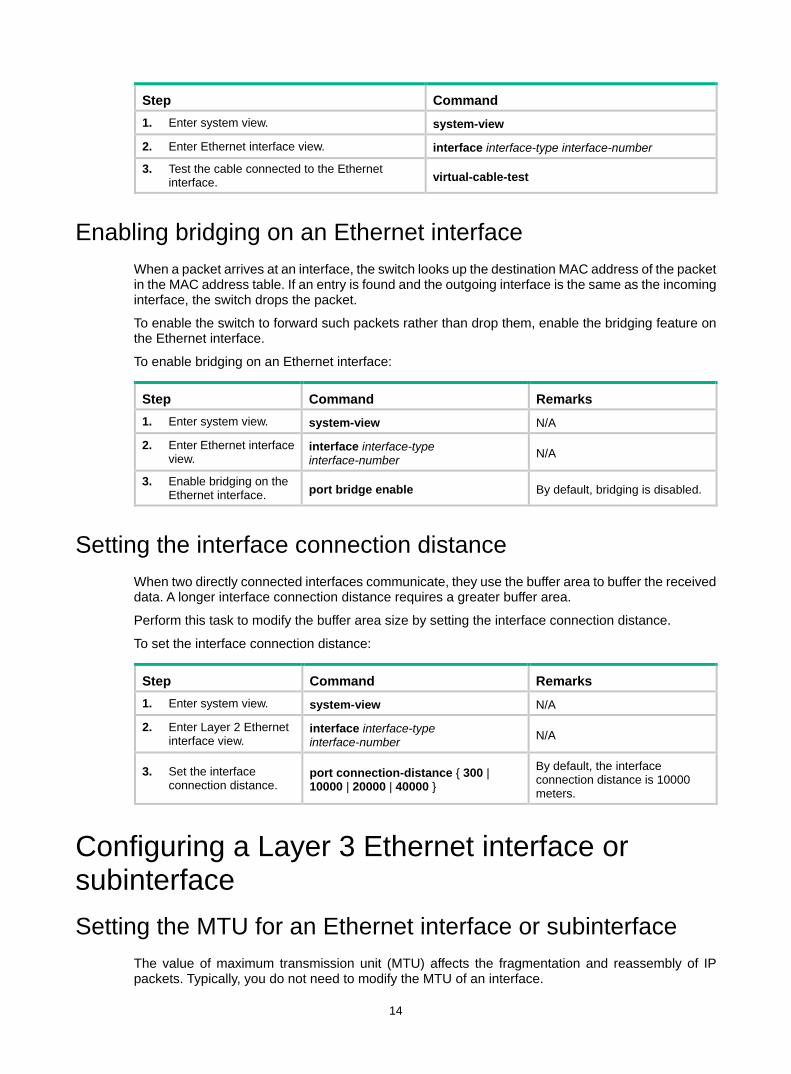
14
Step Command 1. Enter system view. system-view
2. Enter Ethernet interface view. interface interface-type interface-number
3. Test the cable connected to the Ethernet interface. virtual-cable-test
Enabling bridging on an Ethernet interface When a packet arrives at an interface, the switch looks up the destination MAC address of the packet in the MAC address table. If an entry is found and the outgoing interface is the same as the incoming interface, the switch drops the packet.
To enable the switch to forward such packets rather than drop them, enable the bridging feature on the Ethernet interface.
To enable bridging on an Ethernet interface:
Step Command Remarks 1. Enter system view. system-view N/A
2. Enter Ethernet interface view.
interface interface-type interface-number N/A
3. Enable bridging on the Ethernet interface. port bridge enable By default, bridging is disabled.
Setting the interface connection distance When two directly connected interfaces communicate, they use the buffer area to buffer the received data. A longer interface connection distance requires a greater buffer area.
Perform this task to modify the buffer area size by setting the interface connection distance.
To set the interface connection distance:
Step Command Remarks 1. Enter system view. system-view N/A
2. Enter Layer 2 Ethernet interface view.
interface interface-type interface-number N/A
3. Set the interface connection distance.
port connection-distance { 300 | 10000 | 20000 | 40000 }
By default, the interface connection distance is 10000 meters.
Configuring a Layer 3 Ethernet interface or subinterface Setting the MTU for an Ethernet interface or subinterface
The value of maximum transmission unit (MTU) affects the fragmentation and reassembly of IP packets. Typically, you do not need to modify the MTU of an interface.
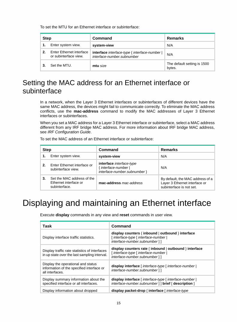
15
To set the MTU for an Ethernet interface or subinterface:
Step Command Remarks 1. Enter system view. system-view N/A
2. Enter Ethernet interface or subinterface view.
interface interface-type { interface-number | interface-number.subnumber N/A
3. Set the MTU. mtu size The default setting is 1500 bytes.
Setting the MAC address for an Ethernet interface or subinterface
In a network, when the Layer 3 Ethernet interfaces or subinterfaces of different devices have the same MAC address, the devices might fail to communicate correctly. To eliminate the MAC address conflicts, use the mac-address command to modify the MAC addresses of Layer 3 Ethernet interfaces or subinterfaces.
When you set a MAC address for a Layer 3 Ethernet interface or subinterface, select a MAC address different from any IRF bridge MAC address. For more information about IRF bridge MAC address, see IRF Configuration Guide.
To set the MAC address of an Ethernet interface or subinterface:
Step Command Remarks 1. Enter system view. system-view N/A
2. Enter Ethernet interface or subinterface view.
interface interface-type { interface-number | interface-number.subnumber }
N/A
3. Set the MAC address of the Ethernet interface or subinterface.
mac-address mac-address By default, the MAC address of a Layer 3 Ethernet interface or subinterface is not set.
Displaying and maintaining an Ethernet interface Execute display commands in any view and reset commands in user view.
Task Command
Display interface traffic statistics. display counters { inbound | outbound } interface [ interface-type [ interface-number | interface-number.subnumber ] ]
Display traffic rate statistics of interfaces in up state over the last sampling interval.
display counters rate { inbound | outbound } interface [ interface-type [ interface-number | interface-number.subnumber ] ]
Display the operational and status information of the specified interface or all interfaces.
display interface [ interface-type [ interface-number | interface-number.subnumber ] ]
Display summary information about the specified interface or all interfaces.
display interface [ interface-type [ interface-number | interface-number.subnumber ] ] brief [ description ]
Display information about dropped display packet-drop { interface [ interface-type

16
Task Command packets on the specified interface or all interfaces.
[ interface-number ] ] | summary }
Display the PFC information for an interface.
display priority-flow-control interface [ interface-type [ interface-number ] ]
Display information about storm control on the specified interface or all interfaces.
display storm-constrain [ broadcast | multicast | unicast ] [ interface interface-type interface-number ]
Display the Ethernet statistics. display ethernet statistics slot slot-number
Clear the interface statistics. reset counters interface [ interface-type [ interface-number | interface-number.subnumber ] ]
Clear the statistics of dropped packets on the specified interfaces.
reset packet-drop interface [ interface-type [ interface-number ] ]
Clear the Ethernet statistics. reset ethernet statistics
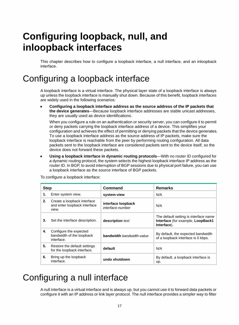
17
Configuring loopback, null, and inloopback interfaces
This chapter describes how to configure a loopback interface, a null interface, and an inloopback interface.
Configuring a loopback interface A loopback interface is a virtual interface. The physical layer state of a loopback interface is always up unless the loopback interface is manually shut down. Because of this benefit, loopback interfaces are widely used in the following scenarios: • Configuring a loopback interface address as the source address of the IP packets that
the device generates—Because loopback interface addresses are stable unicast addresses, they are usually used as device identifications. When you configure a rule on an authentication or security server, you can configure it to permit or deny packets carrying the loopback interface address of a device. This simplifies your configuration and achieves the effect of permitting or denying packets that the device generates. To use a loopback interface address as the source address of IP packets, make sure the loopback interface is reachable from the peer by performing routing configuration. All data packets sent to the loopback interface are considered packets sent to the device itself, so the device does not forward these packets.
• Using a loopback interface in dynamic routing protocols—With no router ID configured for a dynamic routing protocol, the system selects the highest loopback interface IP address as the router ID. In BGP, to avoid interruption of BGP sessions due to physical port failure, you can use a loopback interface as the source interface of BGP packets.
To configure a loopback interface:
Step Command Remarks 1. Enter system view. system-view N/A
2. Create a loopback interface and enter loopback interface view.
interface loopback interface-number N/A
3. Set the interface description. description text The default setting is interface name Interface (for example, LoopBack1 Interface).
4. Configure the expected bandwidth of the loopback interface.
bandwidth bandwidth-value By default, the expected bandwidth of a loopback interface is 0 kbps.
5. Restore the default settings for the loopback interface. default N/A
6. Bring up the loopback interface. undo shutdown By default, a loopback interface is
up.
Configuring a null interface A null interface is a virtual interface and is always up, but you cannot use it to forward data packets or configure it with an IP address or link layer protocol. The null interface provides a simpler way to filter
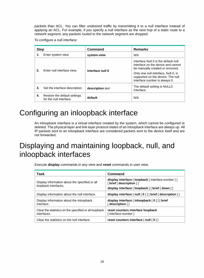
18
packets than ACL. You can filter undesired traffic by transmitting it to a null interface instead of applying an ACL. For example, if you specify a null interface as the next hop of a static route to a network segment, any packets routed to the network segment are dropped.
To configure a null interface:
Step Command Remarks 1. Enter system view. system-view N/A
2. Enter null interface view. interface null 0
Interface Null 0 is the default null interface on the device and cannot be manually created or removed. Only one null interface, Null 0, is supported on the device. The null interface number is always 0.
3. Set the interface description. description text The default setting is NULL0 Interface.
4. Restore the default settings for the null interface. default N/A
Configuring an inloopback interface An inloopback interface is a virtual interface created by the system, which cannot be configured or deleted. The physical layer and link layer protocol states of an inloopback interface are always up. All IP packets sent to an inloopback interface are considered packets sent to the device itself and are not forwarded.
Displaying and maintaining loopback, null, and inloopback interfaces
Execute display commands in any view and reset commands in user view.
Task Command
Display information about the specified or all loopback interfaces.
display interface [ loopback [ interface-number ] ] [ brief [ description ] ] display interface [ loopback ] [ brief [ down ] ]
Display information about the null interface. display interface [ null [ 0 ] ] [ brief [ description ] ]
Display information about the inloopback interface.
display interface [ inloopback [ 0 ] ] [ brief [ description ] ]
Clear the statistics on the specified or all loopback interfaces.
reset counters interface loopback [ interface-number ]
Clear the statistics on the null interface. reset counters interface [ null [ 0 ] ]
19
Bulk configuring interfaces You can enter interface range view to bulk configure multiple interfaces with the same feature instead of configuring them one by one. For example, you can execute the shutdown command in interface range view to shut down a range of interfaces.
Configuration restrictions and guidelines When you bulk configure interfaces in interface range view, follow these restrictions and guidelines: • In interface range view, only the commands supported by the first interface are available. The
first interface is specified with the interface range command. • If you cannot enter the view of an interface by using the interface interface-type
interface-number command, do not configure the interface as the first interface in the interface range.
• Do not assign both an aggregate interface and any of its member interfaces to an interface range. Some commands might break up the aggregation after they are executed on both an aggregate interface and its member interfaces.
• No limit is set on the maximum number of interfaces in an interface range. The more interfaces in an interface range, the longer the command execution time.
• The maximum number of interface range names is limited only by the system resources. As a best practice to guarantee bulk interface configuration performance, configure fewer than 1000 interface range names.
• After a command is executed in interface range view, one of the following situations might occur: The system stays in interface range view and does not display an error message. It means
that the execution succeeded on all member interfaces in the interface range. The system displays an error message and stays in interface range view. It means that the
execution failed on member interfaces in the interface range. − If the execution failed on the first member interface in the interface range, the command
is not executed on any member interfaces. − If the execution failed on non-first member interfaces, the command takes effect on the
other member interfaces. The system returns to system view. It means that:
− The command is supported in both system view and interface view. − The execution failed on a member interface in interface range view and succeeded in
system view. − The command is not executed on the subsequent member interfaces. You can use the display this command to verify the configuration in interface view of each member interface. In addition, if the configuration in system view is not needed, use the undo form of the command to remove the configuration.
Configuration procedure To bulk configure interfaces:
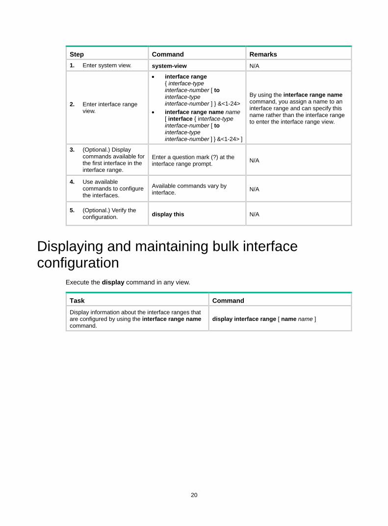
20
Step Command Remarks 1. Enter system view. system-view N/A
2. Enter interface range view.
• interface range { interface-type interface-number [ to interface-type interface-number ] } &<1-24>
• interface range name name [ interface { interface-type interface-number [ to interface-type interface-number ] } &<1-24> ]
By using the interface range name command, you assign a name to an interface range and can specify this name rather than the interface range to enter the interface range view.
3. (Optional.) Display commands available for the first interface in the interface range.
Enter a question mark (?) at the interface range prompt. N/A
4. Use available commands to configure the interfaces.
Available commands vary by interface. N/A
5. (Optional.) Verify the configuration. display this N/A
Displaying and maintaining bulk interface configuration
Execute the display command in any view.
Task Command Display information about the interface ranges that are configured by using the interface range name command.
display interface range [ name name ]

21
Configuring the MAC address table Overview
An Ethernet device uses a MAC address table to forward frames. A MAC address entry includes a destination MAC address, an outgoing interface, and a VLAN ID. When the device receives a frame, it uses the destination MAC address of the frame to look for a match in the MAC address table. • The device forwards the frame out of the outgoing interface in the matching entry if a match is
found. • The device floods the frame in the VLAN of the frame if no match is found.
How a MAC address entry is created The entries in the MAC address table include entries automatically learned by the device and entries manually added.
MAC address learning The device can automatically populate its MAC address table by learning the source MAC addresses of incoming frames on each interface.
When a frame arrives at an interface (for example, port A), the device performs the following operations: 1. Checks the source MAC address (for example, MAC-SOURCE) of the frame. 2. Looks up the source MAC address in the MAC address table.
The device updates the entry if an entry is found. The device adds an entry for MAC-SOURCE and port A if no entry is found.
3. When the device receives a frame destined for MAC-SOURCE after learning this source MAC address, the device performs the following operations: a. Finds the MAC-SOURCE entry in the MAC address table. b. Forwards the frame out of port A.
The device performs the learning process each time it receives a frame with an unknown source MAC address until the table is fully populated.
Manually configuring MAC address entries Dynamic MAC address learning does not distinguish between illegitimate and legitimate frames, which can invite security hazards. When Host A is connected to port A, a MAC address entry will be learned for the MAC address of Host A (for example, MAC A). When an illegal user sends frames with MAC A as the source MAC address to port B, the device performs the following operations: 1. Learns a new MAC address entry with port B as the outgoing interface and overwrites the old
entry for MAC A. 2. Forwards frames destined for MAC A out of port B to the illegal user.
As a result, the illegal user obtains the data of Host A. To improve the security for Host A, manually configure a static entry to bind Host A to port A. Then, the frames destined for Host A are always sent out of port A. Other hosts using the forged MAC address of Host A cannot obtain the frames destined for Host A.
Types of MAC address entries A MAC address table can contain the following types of entries:
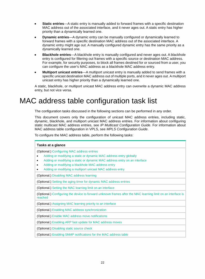
22
• Static entries—A static entry is manually added to forward frames with a specific destination MAC address out of the associated interface, and it never ages out. A static entry has higher priority than a dynamically learned one.
• Dynamic entries—A dynamic entry can be manually configured or dynamically learned to forward frames with a specific destination MAC address out of the associated interface. A dynamic entry might age out. A manually configured dynamic entry has the same priority as a dynamically learned one.
• Blackhole entries—A blackhole entry is manually configured and never ages out. A blackhole entry is configured for filtering out frames with a specific source or destination MAC address. For example, for security purposes, to block all frames destined for or sourced from a user, you can configure the user's MAC address as a blackhole MAC address entry.
• Multiport unicast entries—A multiport unicast entry is manually added to send frames with a specific unicast destination MAC address out of multiple ports, and it never ages out. A multiport unicast entry has higher priority than a dynamically learned one.
A static, blackhole, or multiport unicast MAC address entry can overwrite a dynamic MAC address entry, but not vice versa.
MAC address table configuration task list The configuration tasks discussed in the following sections can be performed in any order.
This document covers only the configuration of unicast MAC address entries, including static, dynamic, blackhole, and multiport unicast MAC address entries. For information about configuring static multicast MAC address entries, see IP Multicast Configuration Guide. For information about MAC address table configuration in VPLS, see MPLS Configuration Guide.
To configure the MAC address table, perform the following tasks:
Tasks at a glance
(Optional.) Configuring MAC address entries • Adding or modifying a static or dynamic MAC address entry globally • Adding or modifying a static or dynamic MAC address entry on an interface • Adding or modifying a blackhole MAC address entry • Adding or modifying a multiport unicast MAC address entry
(Optional.) Disabling MAC address learning
(Optional.) Setting the aging timer for dynamic MAC address entries
(Optional.) Setting the MAC learning limit on an interface
(Optional.) Configuring the device to forward unknown frames after the MAC learning limit on an interface is reached
(Optional.) Assigning MAC learning priority to an interface
(Optional.) Enabling MAC address synchronization
(Optional.) Enable MAC address move notifications
(Optional.) Enabling ARP fast update for MAC address moves
(Optional.) Disabling static source check
(Optional.) Enabling SNMP notifications for the MAC address table
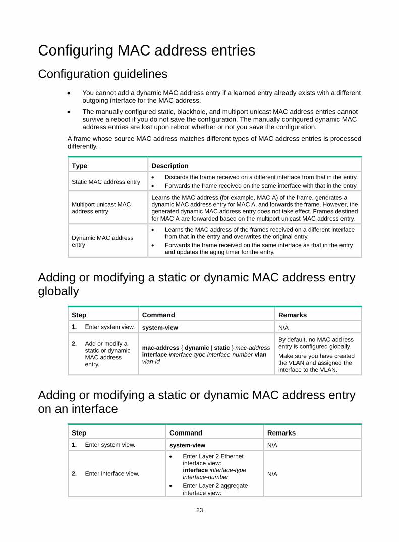
23
Configuring MAC address entries Configuration guidelines
• You cannot add a dynamic MAC address entry if a learned entry already exists with a different outgoing interface for the MAC address.
• The manually configured static, blackhole, and multiport unicast MAC address entries cannot survive a reboot if you do not save the configuration. The manually configured dynamic MAC address entries are lost upon reboot whether or not you save the configuration.
A frame whose source MAC address matches different types of MAC address entries is processed differently.
Type Description
Static MAC address entry • Discards the frame received on a different interface from that in the entry. • Forwards the frame received on the same interface with that in the entry.
Multiport unicast MAC address entry
Learns the MAC address (for example, MAC A) of the frame, generates a dynamic MAC address entry for MAC A, and forwards the frame. However, the generated dynamic MAC address entry does not take effect. Frames destined for MAC A are forwarded based on the multiport unicast MAC address entry.
Dynamic MAC address entry
• Learns the MAC address of the frames received on a different interface from that in the entry and overwrites the original entry.
• Forwards the frame received on the same interface as that in the entry and updates the aging timer for the entry.
Adding or modifying a static or dynamic MAC address entry globally
Step Command Remarks 1. Enter system view. system-view N/A
2. Add or modify a static or dynamic MAC address entry.
mac-address { dynamic | static } mac-address interface interface-type interface-number vlan vlan-id
By default, no MAC address entry is configured globally. Make sure you have created the VLAN and assigned the interface to the VLAN.
Adding or modifying a static or dynamic MAC address entry on an interface
Step Command Remarks 1. Enter system view. system-view N/A
2. Enter interface view.
• Enter Layer 2 Ethernet interface view: interface interface-type interface-number
• Enter Layer 2 aggregate interface view:
N/A
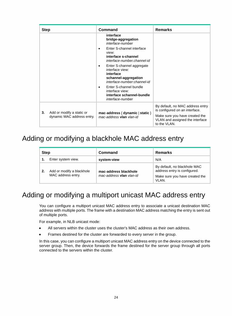
24
Step Command Remarks interface bridge-aggregation interface-number
• Enter S-channel interface view: interface s-channel interface-number.channel-id
• Enter S-channel aggregate interface view: interface schannel-aggregation interface-number:channel-id
• Enter S-channel bundle interface view: interface schannel-bundle interface-number
3. Add or modify a static or dynamic MAC address entry.
mac-address { dynamic | static } mac-address vlan vlan-id
By default, no MAC address entry is configured on an interface. Make sure you have created the VLAN and assigned the interface to the VLAN.
Adding or modifying a blackhole MAC address entry
Step Command Remarks 1. Enter system view. system-view N/A
2. Add or modify a blackhole MAC address entry.
mac-address blackhole mac-address vlan vlan-id
By default, no blackhole MAC address entry is configured. Make sure you have created the VLAN.
Adding or modifying a multiport unicast MAC address entry You can configure a multiport unicast MAC address entry to associate a unicast destination MAC address with multiple ports. The frame with a destination MAC address matching the entry is sent out of multiple ports.
For example, in NLB unicast mode: • All servers within the cluster uses the cluster's MAC address as their own address. • Frames destined for the cluster are forwarded to every server in the group.
In this case, you can configure a multiport unicast MAC address entry on the device connected to the server group. Then, the device forwards the frame destined for the server group through all ports connected to the servers within the cluster.
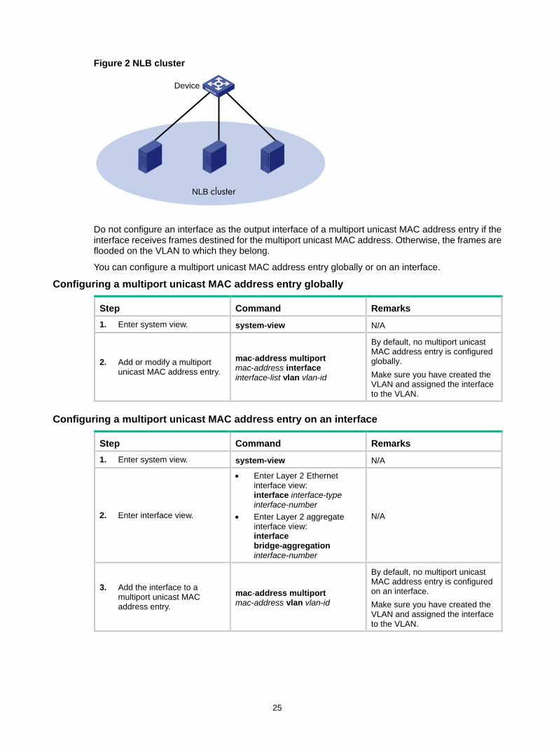
25
Figure 2 NLB cluster
Do not configure an interface as the output interface of a multiport unicast MAC address entry if the interface receives frames destined for the multiport unicast MAC address. Otherwise, the frames are flooded on the VLAN to which they belong.
You can configure a multiport unicast MAC address entry globally or on an interface.
Configuring a multiport unicast MAC address entry globally
Step Command Remarks 1. Enter system view. system-view N/A
2. Add or modify a multiport unicast MAC address entry.
mac-address multiport mac-address interface interface-list vlan vlan-id
By default, no multiport unicast MAC address entry is configured globally. Make sure you have created the VLAN and assigned the interface to the VLAN.
Configuring a multiport unicast MAC address entry on an interface
Step Command Remarks 1. Enter system view. system-view N/A
2. Enter interface view.
• Enter Layer 2 Ethernet interface view: interface interface-type interface-number
• Enter Layer 2 aggregate interface view: interface bridge-aggregation interface-number
N/A
3. Add the interface to a multiport unicast MAC address entry.
mac-address multiport mac-address vlan vlan-id
By default, no multiport unicast MAC address entry is configured on an interface. Make sure you have created the VLAN and assigned the interface to the VLAN.
NLB cluster
Device
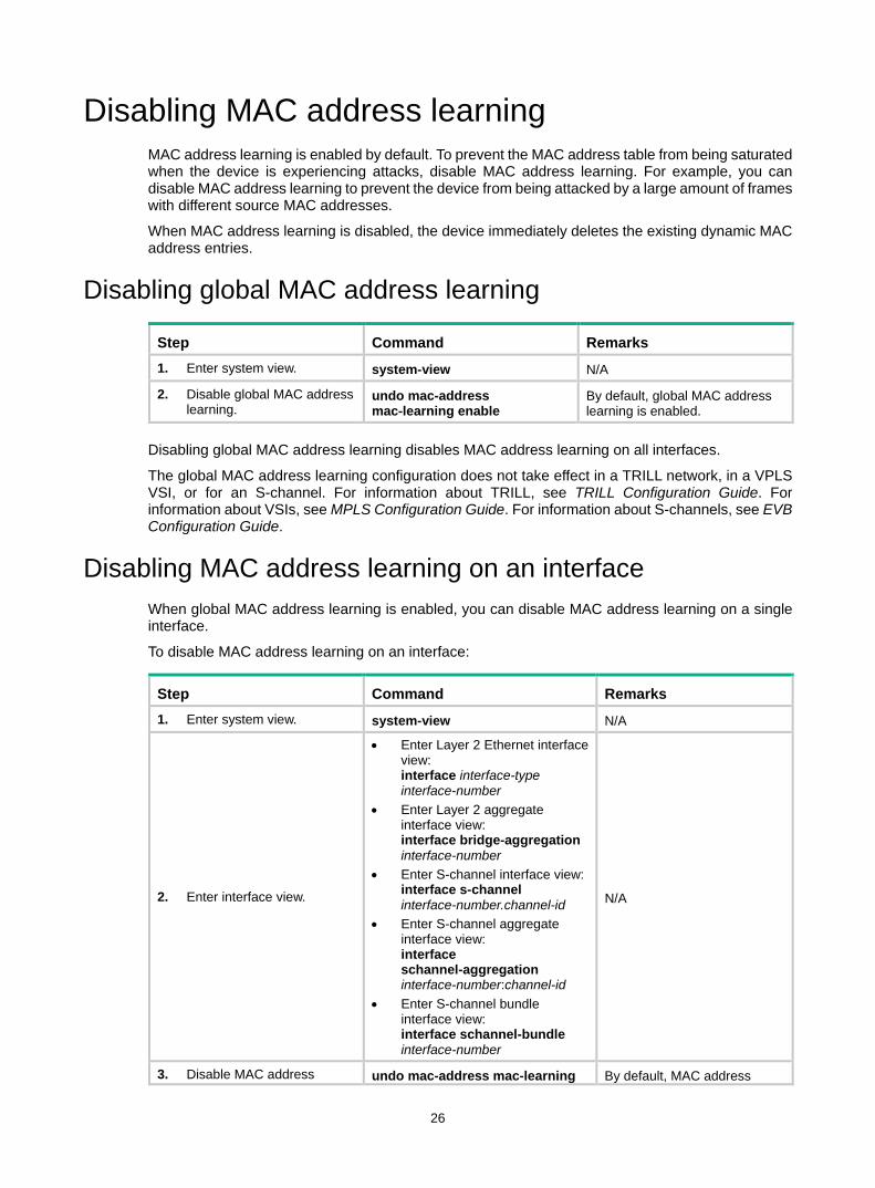
26
Disabling MAC address learning MAC address learning is enabled by default. To prevent the MAC address table from being saturated when the device is experiencing attacks, disable MAC address learning. For example, you can disable MAC address learning to prevent the device from being attacked by a large amount of frames with different source MAC addresses.
When MAC address learning is disabled, the device immediately deletes the existing dynamic MAC address entries.
Disabling global MAC address learning
Step Command Remarks 1. Enter system view. system-view N/A
2. Disable global MAC address learning.
undo mac-address mac-learning enable
By default, global MAC address learning is enabled.
Disabling global MAC address learning disables MAC address learning on all interfaces.
The global MAC address learning configuration does not take effect in a TRILL network, in a VPLS VSI, or for an S-channel. For information about TRILL, see TRILL Configuration Guide. For information about VSIs, see MPLS Configuration Guide. For information about S-channels, see EVB Configuration Guide.
Disabling MAC address learning on an interface When global MAC address learning is enabled, you can disable MAC address learning on a single interface.
To disable MAC address learning on an interface:
Step Command Remarks 1. Enter system view. system-view N/A
2. Enter interface view.
• Enter Layer 2 Ethernet interface view: interface interface-type interface-number
• Enter Layer 2 aggregate interface view: interface bridge-aggregation interface-number
• Enter S-channel interface view: interface s-channel interface-number.channel-id
• Enter S-channel aggregate interface view: interface schannel-aggregation interface-number:channel-id
• Enter S-channel bundle interface view: interface schannel-bundle interface-number
N/A
3. Disable MAC address undo mac-address mac-learning By default, MAC address
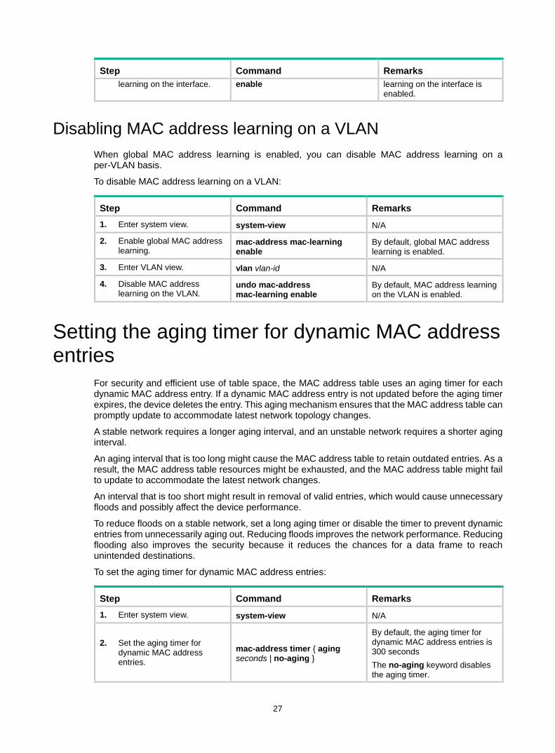
27
Step Command Remarks learning on the interface. enable learning on the interface is
enabled.
Disabling MAC address learning on a VLAN When global MAC address learning is enabled, you can disable MAC address learning on a per-VLAN basis.
To disable MAC address learning on a VLAN:
Step Command Remarks 1. Enter system view. system-view N/A
2. Enable global MAC address learning.
mac-address mac-learning enable
By default, global MAC address learning is enabled.
3. Enter VLAN view. vlan vlan-id N/A
4. Disable MAC address learning on the VLAN.
undo mac-address mac-learning enable
By default, MAC address learning on the VLAN is enabled.
Setting the aging timer for dynamic MAC address entries
For security and efficient use of table space, the MAC address table uses an aging timer for each dynamic MAC address entry. If a dynamic MAC address entry is not updated before the aging timer expires, the device deletes the entry. This aging mechanism ensures that the MAC address table can promptly update to accommodate latest network topology changes.
A stable network requires a longer aging interval, and an unstable network requires a shorter aging interval.
An aging interval that is too long might cause the MAC address table to retain outdated entries. As a result, the MAC address table resources might be exhausted, and the MAC address table might fail to update to accommodate the latest network changes.
An interval that is too short might result in removal of valid entries, which would cause unnecessary floods and possibly affect the device performance.
To reduce floods on a stable network, set a long aging timer or disable the timer to prevent dynamic entries from unnecessarily aging out. Reducing floods improves the network performance. Reducing flooding also improves the security because it reduces the chances for a data frame to reach unintended destinations.
To set the aging timer for dynamic MAC address entries:
Step Command Remarks 1. Enter system view. system-view N/A
2. Set the aging timer for dynamic MAC address entries.
mac-address timer { aging seconds | no-aging }
By default, the aging timer for dynamic MAC address entries is 300 seconds The no-aging keyword disables the aging timer.
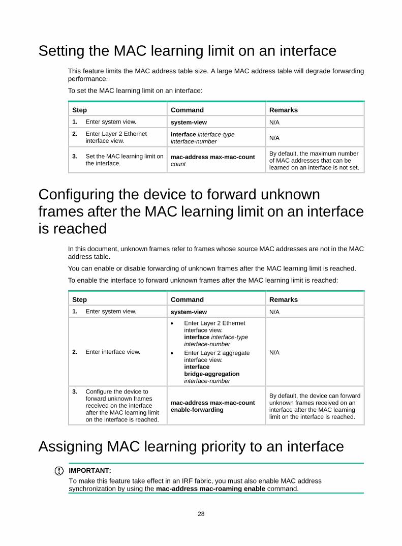
28
Setting the MAC learning limit on an interface This feature limits the MAC address table size. A large MAC address table will degrade forwarding performance.
To set the MAC learning limit on an interface:
Step Command Remarks 1. Enter system view. system-view N/A
2. Enter Layer 2 Ethernet interface view.
interface interface-type interface-number N/A
3. Set the MAC learning limit on the interface.
mac-address max-mac-count count
By default, the maximum number of MAC addresses that can be learned on an interface is not set.
Configuring the device to forward unknown frames after the MAC learning limit on an interface is reached
In this document, unknown frames refer to frames whose source MAC addresses are not in the MAC address table.
You can enable or disable forwarding of unknown frames after the MAC learning limit is reached.
To enable the interface to forward unknown frames after the MAC learning limit is reached:
Step Command Remarks 1. Enter system view. system-view N/A
2. Enter interface view.
• Enter Layer 2 Ethernet interface view. interface interface-type interface-number
• Enter Layer 2 aggregate interface view. interface bridge-aggregation interface-number
N/A
3. Configure the device to forward unknown frames received on the interface after the MAC learning limit on the interface is reached.
mac-address max-mac-count enable-forwarding
By default, the device can forward unknown frames received on an interface after the MAC learning limit on the interface is reached.
Assigning MAC learning priority to an interface IMPORTANT:
To make this feature take effect in an IRF fabric, you must also enable MAC address synchronization by using the mac-address mac-roaming enable command.
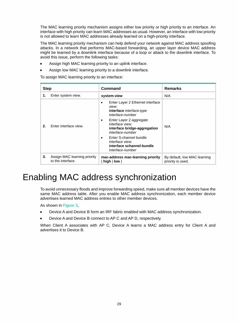
29
The MAC learning priority mechanism assigns either low priority or high priority to an interface. An interface with high priority can learn MAC addresses as usual. However, an interface with low priority is not allowed to learn MAC addresses already learned on a high-priority interface.
The MAC learning priority mechanism can help defend your network against MAC address spoofing attacks. In a network that performs MAC-based forwarding, an upper layer device MAC address might be learned by a downlink interface because of a loop or attack to the downlink interface. To avoid this issue, perform the following tasks: • Assign high MAC learning priority to an uplink interface. • Assign low MAC learning priority to a downlink interface.
To assign MAC learning priority to an interface:
Step Command Remarks 1. Enter system view. system-view N/A
2. Enter interface view.
• Enter Layer 2 Ethernet interface view: interface interface-type interface-number
• Enter Layer 2 aggregate interface view: interface bridge-aggregation interface-number
• Enter S-channel bundle interface view: interface schannel-bundle interface-number
N/A
3. Assign MAC learning priority to the interface.
mac-address mac-learning priority { high | low }
By default, low MAC learning priority is used.
Enabling MAC address synchronization To avoid unnecessary floods and improve forwarding speed, make sure all member devices have the same MAC address table. After you enable MAC address synchronization, each member device advertises learned MAC address entries to other member devices.
As shown in Figure 3, • Device A and Device B form an IRF fabric enabled with MAC address synchronization. • Device A and Device B connect to AP C and AP D, respectively.
When Client A associates with AP C, Device A learns a MAC address entry for Client A and advertises it to Device B.
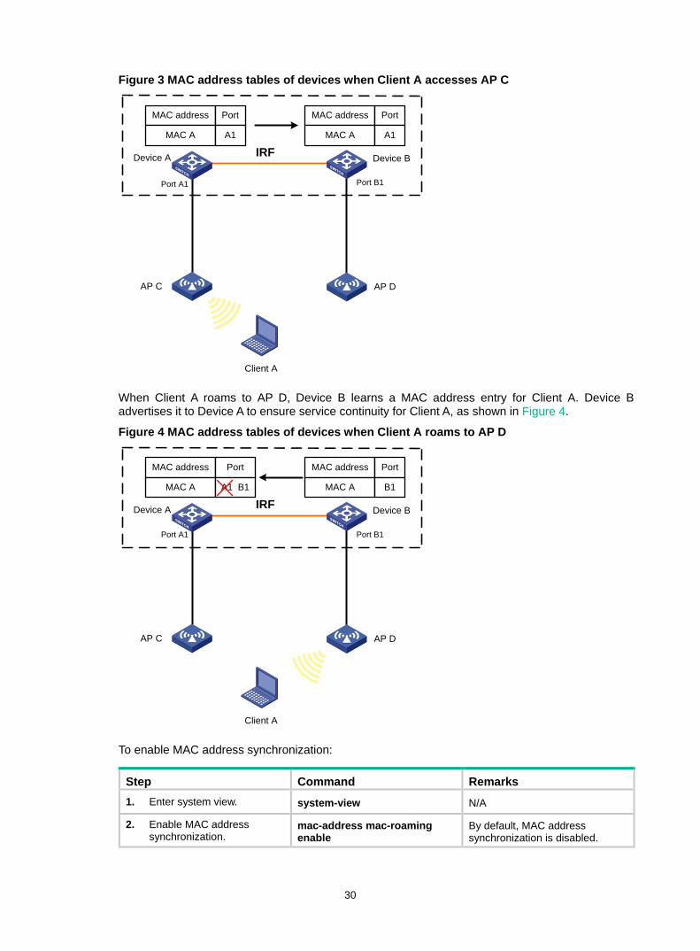
30
Figure 3 MAC address tables of devices when Client A accesses AP C
When Client A roams to AP D, Device B learns a MAC address entry for Client A. Device B advertises it to Device A to ensure service continuity for Client A, as shown in Figure 4.
Figure 4 MAC address tables of devices when Client A roams to AP D
To enable MAC address synchronization:
Step Command Remarks 1. Enter system view. system-view N/A
2. Enable MAC address synchronization.
mac-address mac-roaming enable
By default, MAC address synchronization is disabled.
IRFDevice A Device B
Client A
AP DAP C
Port A1 Port B1
MAC address Port
MAC A A1
MAC address Port
MAC A A1
IRFDevice A Device B
Client A
AP DAP C
Port A1 Port B1
MAC address Port
MAC A A1 B1
MAC address Port
MAC A B1
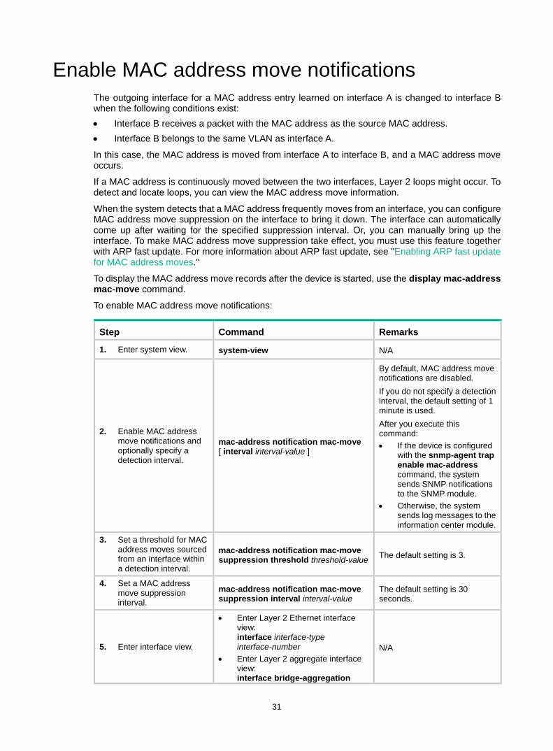
31
Enable MAC address move notifications The outgoing interface for a MAC address entry learned on interface A is changed to interface B when the following conditions exist: • Interface B receives a packet with the MAC address as the source MAC address. • Interface B belongs to the same VLAN as interface A.
In this case, the MAC address is moved from interface A to interface B, and a MAC address move occurs.
If a MAC address is continuously moved between the two interfaces, Layer 2 loops might occur. To detect and locate loops, you can view the MAC address move information.
When the system detects that a MAC address frequently moves from an interface, you can configure MAC address move suppression on the interface to bring it down. The interface can automatically come up after waiting for the specified suppression interval. Or, you can manually bring up the interface. To make MAC address move suppression take effect, you must use this feature together with ARP fast update. For more information about ARP fast update, see "Enabling ARP fast update for MAC address moves."
To display the MAC address move records after the device is started, use the display mac-address mac-move command.
To enable MAC address move notifications:
Step Command Remarks
1. Enter system view. system-view N/A
2. Enable MAC address move notifications and optionally specify a detection interval.
mac-address notification mac-move [ interval interval-value ]
By default, MAC address move notifications are disabled. If you do not specify a detection interval, the default setting of 1 minute is used. After you execute this command: • If the device is configured
with the snmp-agent trap enable mac-address command, the system sends SNMP notifications to the SNMP module.
• Otherwise, the system sends log messages to the information center module.
3. Set a threshold for MAC address moves sourced from an interface within a detection interval.
mac-address notification mac-move suppression threshold threshold-value The default setting is 3.
4. Set a MAC address move suppression interval.
mac-address notification mac-move suppression interval interval-value
The default setting is 30 seconds.
5. Enter interface view.
• Enter Layer 2 Ethernet interface view: interface interface-type interface-number
• Enter Layer 2 aggregate interface view: interface bridge-aggregation
N/A

32
Step Command Remarks interface-number
6. Enable MAC address move suppression.
mac-address notification mac-move suppression
By default, MAC address move suppression is disabled.
7. Return to system view. quit N/A
8. Enable ARP fast update for MAC address moves.
mac-address mac-move fast-update
This task is required when you enable MAC address move suppression. By default, ARP fast update for MAC address moves is disabled.
Enabling ARP fast update for MAC address moves
ARP fast update for MAC address moves allows the device to update an ARP entry immediately after the outgoing interface for a MAC address changes. This feature ensures data connection without interruption.
As shown in Figure 5, a mobile user Laptop accesses the network by connecting to AP 1 or AP 2. When the AP to which the user connects changes, the switch updates the ARP entry for the user immediately after it detects a MAC address move.
Figure 5 ARP fast update application scenario
To enable ARP fast update for MAC address moves:
Step Command Remarks 1. Enter system
view. system-view N/A
2. Enable ARP fast update for MAC address moves.
mac-address mac-move fast-update By default, ARP fast update for MAC address moves is disabled.
AP 2
Switch
AP 1
FGE1/0/1 FGE1/0/2
Laptop

33
Disabling static source check By default, the static source check feature is enabled on an interface. The check identifies whether a received frame meets the following conditions: • The source MAC address of the frame matches a static MAC address entry. • The incoming interface of the frame is different from the outgoing interface in the entry.
If the frame meets both conditions, the switch drops the frame.
When this feature is disabled, the switch does not perform the check for a received frame. It can forward the frame whether or not the frame meets the conditions.
To disable the static source check feature:
Step Command Remarks 1. Enter system
view. system-view N/A
2. Enter interface view.
• Enter Layer 2 Ethernet interface view: interface interface-type interface-number
• Enter Layer 2 aggregate interface view: interface bridge-aggregation interface-number
• Enter Layer 3 Ethernet interface/subinterface view: interface interface-type { interface-number | interface-number.subnumber }
• Enter Layer 3 aggregate interface/subinterface view: interface route-aggregation { interface-number | interface-number.subnumber }
N/A
3. Disable the static source check feature.
undo mac-address static source-check enable
By default, the static source check feature is enabled.
Enabling SNMP notifications for the MAC address table
After you enable SNMP notifications for the MAC address table, the device will send SNMP notifications to the SNMP module to notify the NMS of important events. You can set the notification sending parameters in SNMP to determine the attributes of sending notifications.
After you disable SNMP notifications for the MAC address table, the device will send log messages to the information center module. You can set the output rules and destinations to examine the log messages of the MAC address table module.
For more information about SNMP notifications and information center, see Network Management and Monitoring Configuration Guide.
To enable SNMP notifications for the MAC address table:
Step Command Remarks 1. Enter system system-view N/A
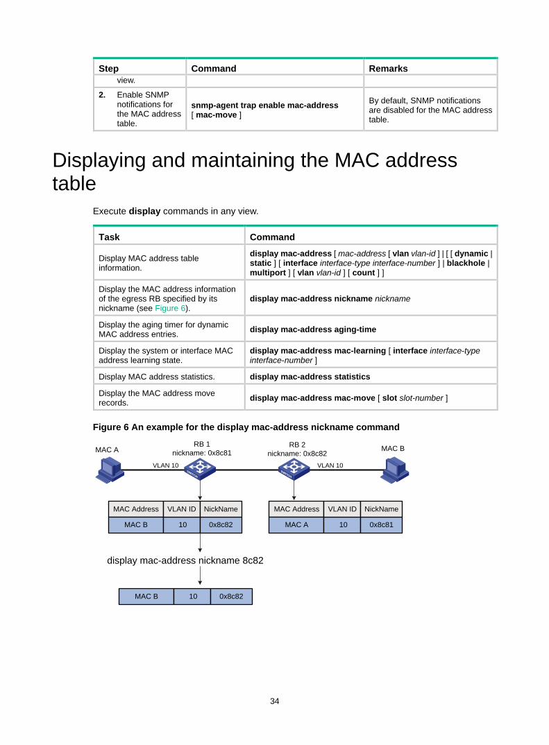
34
Step Command Remarks view.
2. Enable SNMP notifications for the MAC address table.
snmp-agent trap enable mac-address [ mac-move ]
By default, SNMP notifications are disabled for the MAC address table.
Displaying and maintaining the MAC address table
Execute display commands in any view.
Task Command
Display MAC address table information.
display mac-address [ mac-address [ vlan vlan-id ] | [ [ dynamic | static ] [ interface interface-type interface-number ] | blackhole | multiport ] [ vlan vlan-id ] [ count ] ]
Display the MAC address information of the egress RB specified by its nickname (see Figure 6).
display mac-address nickname nickname
Display the aging timer for dynamic MAC address entries. display mac-address aging-time
Display the system or interface MAC address learning state.
display mac-address mac-learning [ interface interface-type interface-number ]
Display MAC address statistics. display mac-address statistics
Display the MAC address move records. display mac-address mac-move [ slot slot-number ]
Figure 6 An example for the display mac-address nickname command
MAC A MAC B
VLAN 10 VLAN 10
MAC Address
MAC B 10
VLAN ID MAC Address
MAC A 10
VLAN ID
display mac-address nickname 8c82
RB 2nickname: 0x8c82
RB 1nickname: 0x8c81
MAC B 10
0x8c82
NickName
0x8c81
NickName
0x8c82
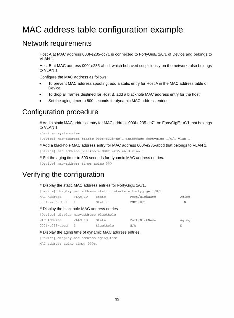
35
MAC address table configuration example Network requirements
Host A at MAC address 000f-e235-dc71 is connected to FortyGigE 1/0/1 of Device and belongs to VLAN 1.
Host B at MAC address 000f-e235-abcd, which behaved suspiciously on the network, also belongs to VLAN 1.
Configure the MAC address as follows: • To prevent MAC address spoofing, add a static entry for Host A in the MAC address table of
Device. • To drop all frames destined for Host B, add a blackhole MAC address entry for the host. • Set the aging timer to 500 seconds for dynamic MAC address entries.
Configuration procedure # Add a static MAC address entry for MAC address 000f-e235-dc71 on FortyGigE 1/0/1 that belongs to VLAN 1. <Device> system-view
[Device] mac-address static 000f-e235-dc71 interface fortygige 1/0/1 vlan 1
# Add a blackhole MAC address entry for MAC address 000f-e235-abcd that belongs to VLAN 1. [Device] mac-address blackhole 000f-e235-abcd vlan 1
# Set the aging timer to 500 seconds for dynamic MAC address entries. [Device] mac-address timer aging 500
Verifying the configuration # Display the static MAC address entries for FortyGigE 1/0/1. [Device] display mac-address static interface fortygige 1/0/1
MAC Address VLAN ID State Port/NickName Aging
000f-e235-dc71 1 Static FGE1/0/1 N
# Display the blackhole MAC address entries. [Device] display mac-address blackhole
MAC Address VLAN ID State Port/NickName Aging
000f-e235-abcd 1 Blackhole N/A N
# Display the aging time of dynamic MAC address entries. [Device] display mac-address aging-time
MAC address aging time: 500s.
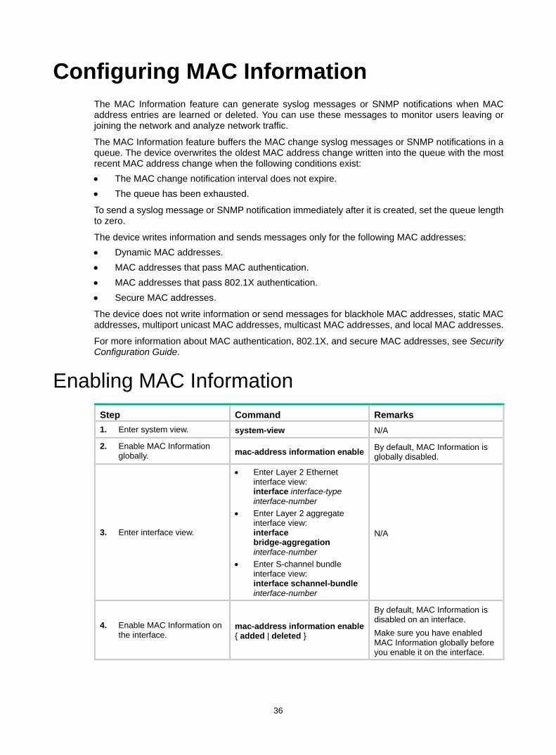
36
Configuring MAC Information The MAC Information feature can generate syslog messages or SNMP notifications when MAC address entries are learned or deleted. You can use these messages to monitor users leaving or joining the network and analyze network traffic.
The MAC Information feature buffers the MAC change syslog messages or SNMP notifications in a queue. The device overwrites the oldest MAC address change written into the queue with the most recent MAC address change when the following conditions exist: • The MAC change notification interval does not expire. • The queue has been exhausted.
To send a syslog message or SNMP notification immediately after it is created, set the queue length to zero.
The device writes information and sends messages only for the following MAC addresses: • Dynamic MAC addresses. • MAC addresses that pass MAC authentication. • MAC addresses that pass 802.1X authentication. • Secure MAC addresses.
The device does not write information or send messages for blackhole MAC addresses, static MAC addresses, multiport unicast MAC addresses, multicast MAC addresses, and local MAC addresses.
For more information about MAC authentication, 802.1X, and secure MAC addresses, see Security Configuration Guide.
Enabling MAC Information Step Command Remarks 1. Enter system view. system-view N/A
2. Enable MAC Information globally. mac-address information enable By default, MAC Information is
globally disabled.
3. Enter interface view.
• Enter Layer 2 Ethernet interface view: interface interface-type interface-number
• Enter Layer 2 aggregate interface view: interface bridge-aggregation interface-number
• Enter S-channel bundle interface view: interface schannel-bundle interface-number
N/A
4. Enable MAC Information on the interface.
mac-address information enable { added | deleted }
By default, MAC Information is disabled on an interface. Make sure you have enabled MAC Information globally before you enable it on the interface.
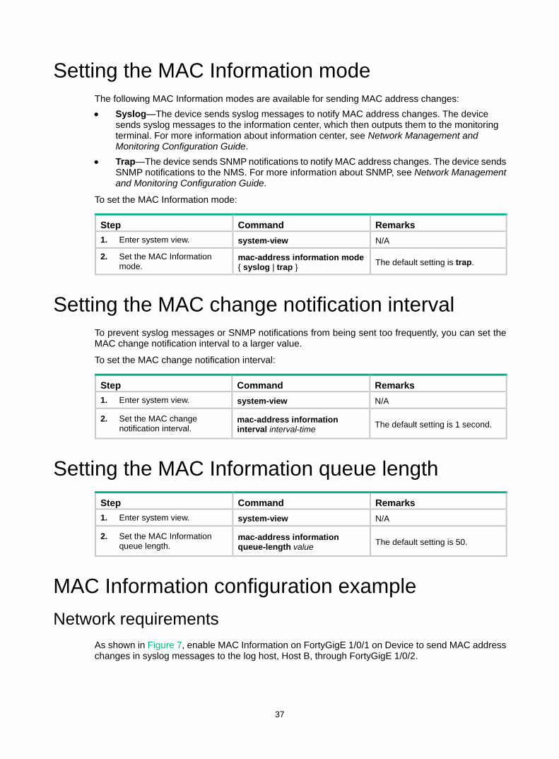
37
Setting the MAC Information mode The following MAC Information modes are available for sending MAC address changes: • Syslog—The device sends syslog messages to notify MAC address changes. The device
sends syslog messages to the information center, which then outputs them to the monitoring terminal. For more information about information center, see Network Management and Monitoring Configuration Guide.
• Trap—The device sends SNMP notifications to notify MAC address changes. The device sends SNMP notifications to the NMS. For more information about SNMP, see Network Management and Monitoring Configuration Guide.
To set the MAC Information mode:
Step Command Remarks 1. Enter system view. system-view N/A
2. Set the MAC Information mode.
mac-address information mode { syslog | trap } The default setting is trap.
Setting the MAC change notification interval To prevent syslog messages or SNMP notifications from being sent too frequently, you can set the MAC change notification interval to a larger value.
To set the MAC change notification interval:
Step Command Remarks 1. Enter system view. system-view N/A
2. Set the MAC change notification interval.
mac-address information interval interval-time The default setting is 1 second.
Setting the MAC Information queue length Step Command Remarks 1. Enter system view. system-view N/A
2. Set the MAC Information queue length.
mac-address information queue-length value The default setting is 50.
MAC Information configuration example Network requirements
As shown in Figure 7, enable MAC Information on FortyGigE 1/0/1 on Device to send MAC address changes in syslog messages to the log host, Host B, through FortyGigE 1/0/2.
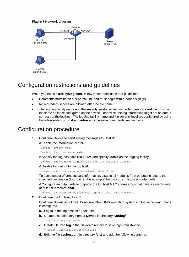
38
Figure 7 Network diagram
Configuration restrictions and guidelines When you edit file /etc/syslog.conf, follow these restrictions and guidelines: • Comments must be on a separate line and must begin with a pound sign (#). • No redundant spaces are allowed after the file name. • The logging facility name and the severity level specified in the /etc/syslog.conf file must be
the same as those configured on the device. Otherwise, the log information might not be output correctly to the log host. The logging facility name and the severity level are configured by using the info-center loghost and info-center source commands, respectively.
Configuration procedure 1. Configure Device to send syslog messages to Host B:
# Enable the information center. <Device> system-view
[Device] info-center enable
# Specify the log host 192.168.1.2/24 and specify local4 as the logging facility. [Device] info-center loghost 192.168.1.2 facility local4
# Disable log output to the log host. [Device] info-center source default loghost deny
To avoid output of unnecessary information, disable all modules from outputting logs to the specified destination (loghost, in this example) before you configure an output rule. # Configure an output rule to output to the log host MAC address logs that have a severity level of at least informational. [Device] info-center source mac loghost level informational
2. Configure the log host, Host B: Configure Solaris as follows. Configure other UNIX operating systems in the same way Solaris is configured. a. Log in to the log host as a root user. b. Create a subdirectory named Device in directory /var/log/.
# mkdir /var/log/Device
c. Create file info.log in the Device directory to save logs from Device. # touch /var/log/Device/info.log
d. Edit the file syslog.conf in directory /etc/ and add the following contents:
Server192.168.1.3/24
DeviceFGE1/0/1 FGE1/0/3
FGE1/0/2Host A192.168.1.1/24
Host B192.168.1.2/24
39
# Device configuration messages
local4.info /var/log/Device/info.log
In this configuration, local4 is the name of the logging facility that the log host uses to receive logs, and info is the informational level. The UNIX system records the log information that has a severity level of at least informational to the file /var/log/Device/info.log.
e. Display the process ID of syslogd, end the syslogd process, and then restart syslogd using the –r option to make the new configuration take effect. # ps -ae | grep syslogd
147
# kill -HUP 147
# syslogd -r &
The device can output MAC address logs to the log host, which stores the logs to the specified file.
3. Enable MAC Information on Device: # Enable MAC Information globally. [Device] mac-address information enable
# Configure the MAC Information mode as syslog. [Device] mac-address information mode syslog
# Enable MAC Information on FortyGigE 1/0/1 to enable FortyGigE 1/0/1 to record MAC address change information when the interface performs either of the following operations: Learns a new MAC address. Deletes an existing MAC address. [Device] interface fortygige 1/0/1
[Device-FortyGigE1/0/1] mac-address information enable added
[Device-FortyGigE1/0/1] mac-address information enable deleted
[Device-FortyGigE1/0/1] quit
# Set the MAC Information queue length to 100. [Device] mac-address information queue-length 100
# Set the MAC change notification interval to 20 seconds. [Device] mac-address information interval 20
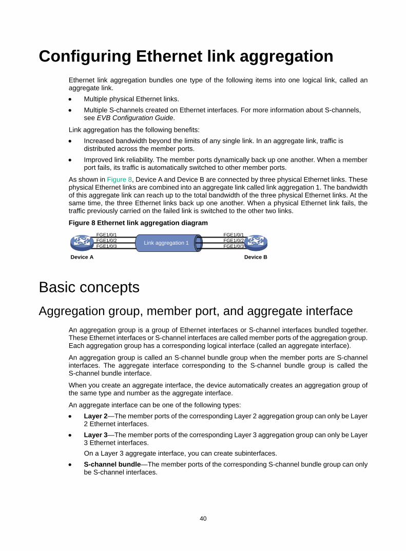
40
Configuring Ethernet link aggregation Ethernet link aggregation bundles one type of the following items into one logical link, called an aggregate link. • Multiple physical Ethernet links. • Multiple S-channels created on Ethernet interfaces. For more information about S-channels,
see EVB Configuration Guide.
Link aggregation has the following benefits: • Increased bandwidth beyond the limits of any single link. In an aggregate link, traffic is
distributed across the member ports. • Improved link reliability. The member ports dynamically back up one another. When a member
port fails, its traffic is automatically switched to other member ports.
As shown in Figure 8, Device A and Device B are connected by three physical Ethernet links. These physical Ethernet links are combined into an aggregate link called link aggregation 1. The bandwidth of this aggregate link can reach up to the total bandwidth of the three physical Ethernet links. At the same time, the three Ethernet links back up one another. When a physical Ethernet link fails, the traffic previously carried on the failed link is switched to the other two links.
Figure 8 Ethernet link aggregation diagram
Basic concepts Aggregation group, member port, and aggregate interface
An aggregation group is a group of Ethernet interfaces or S-channel interfaces bundled together. These Ethernet interfaces or S-channel interfaces are called member ports of the aggregation group. Each aggregation group has a corresponding logical interface (called an aggregate interface).
An aggregation group is called an S-channel bundle group when the member ports are S-channel interfaces. The aggregate interface corresponding to the S-channel bundle group is called the S-channel bundle interface.
When you create an aggregate interface, the device automatically creates an aggregation group of the same type and number as the aggregate interface.
An aggregate interface can be one of the following types: • Layer 2—The member ports of the corresponding Layer 2 aggregation group can only be Layer
2 Ethernet interfaces. • Layer 3—The member ports of the corresponding Layer 3 aggregation group can only be Layer
3 Ethernet interfaces. On a Layer 3 aggregate interface, you can create subinterfaces.
• S-channel bundle—The member ports of the corresponding S-channel bundle group can only be S-channel interfaces.
FGE1/0/2FGE1/0/1
FGE1/0/3 Link aggregation 1 FGE1/0/2
FGE1/0/1
FGE1/0/3
Device A Device B
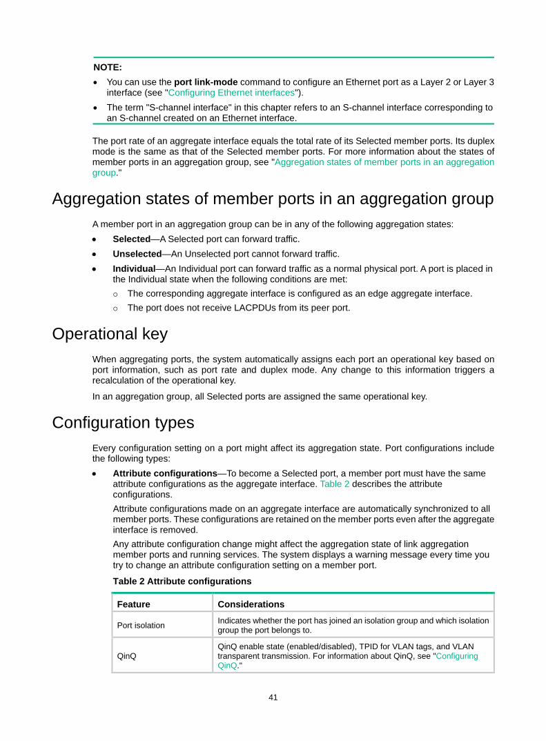
41
NOTE: • You can use the port link-mode command to configure an Ethernet port as a Layer 2 or Layer 3
interface (see "Configuring Ethernet interfaces"). • The term "S-channel interface" in this chapter refers to an S-channel interface corresponding to
an S-channel created on an Ethernet interface.
The port rate of an aggregate interface equals the total rate of its Selected member ports. Its duplex mode is the same as that of the Selected member ports. For more information about the states of member ports in an aggregation group, see "Aggregation states of member ports in an aggregation group."
Aggregation states of member ports in an aggregation group A member port in an aggregation group can be in any of the following aggregation states: • Selected—A Selected port can forward traffic. • Unselected—An Unselected port cannot forward traffic. • Individual—An Individual port can forward traffic as a normal physical port. A port is placed in
the Individual state when the following conditions are met: The corresponding aggregate interface is configured as an edge aggregate interface. The port does not receive LACPDUs from its peer port.
Operational key When aggregating ports, the system automatically assigns each port an operational key based on port information, such as port rate and duplex mode. Any change to this information triggers a recalculation of the operational key.
In an aggregation group, all Selected ports are assigned the same operational key.
Configuration types Every configuration setting on a port might affect its aggregation state. Port configurations include the following types: • Attribute configurations—To become a Selected port, a member port must have the same
attribute configurations as the aggregate interface. Table 2 describes the attribute configurations. Attribute configurations made on an aggregate interface are automatically synchronized to all member ports. These configurations are retained on the member ports even after the aggregate interface is removed. Any attribute configuration change might affect the aggregation state of link aggregation member ports and running services. The system displays a warning message every time you try to change an attribute configuration setting on a member port.
Table 2 Attribute configurations
Feature Considerations
Port isolation Indicates whether the port has joined an isolation group and which isolation group the port belongs to.
QinQ QinQ enable state (enabled/disabled), TPID for VLAN tags, and VLAN transparent transmission. For information about QinQ, see "Configuring QinQ."

42
Feature Considerations
VLAN mapping Different types of VLAN mapping configured on the port. For more information about VLAN mapping, see "Configuring VLAN mapping."
VLAN
• Permitted VLAN IDs. • PVID. • Link type (trunk, hybrid, or access). • Operating mode (promiscuous, trunk promiscuous, host). • VLAN tagging mode. For information about VLAN, see "Configuring VLANs."
• Protocol configurations—Protocol configurations do not affect the aggregation state of the member ports. MAC address learning and spanning tree settings are examples of protocol configurations.
NOTE: The protocol configuration for a member port is effective only when the member port leaves the aggregation group.
Link aggregation modes An aggregation group operates in one of the following modes: • Static—Static aggregation is stable. An aggregation group in static mode is called a static
aggregation group. The aggregation states of the member ports in a static aggregation group are not affected by the peer ports.
• Dynamic—An aggregation group in dynamic mode is called a dynamic aggregation group. The local system and the peer system automatically maintain the aggregation states of the member ports. Dynamic link aggregation reduces the administrators' workload.
Aggregating links in static mode Choosing a reference port
When setting the aggregation state of the ports in an aggregation group, the system automatically chooses a member port as the reference port. A Selected port must have the same operational key and attribute configurations as the reference port.
The system chooses a reference port from the member ports in up state.
The candidate reference ports are organized into different priority levels following these rules: 1. In descending order of port priority. 2. Full duplex. 3. In descending order of speed. 4. Half duplex. 5. In descending order of speed.
From the candidate ports with the same attribute configurations as the aggregate interface, the one with the highest priority level is chosen as the reference port. • If multiple ports have the same priority level, the port that has been Selected (if any) is chosen.
If multiple ports with the same priority level have been Selected, the one with the smallest port number is chosen.
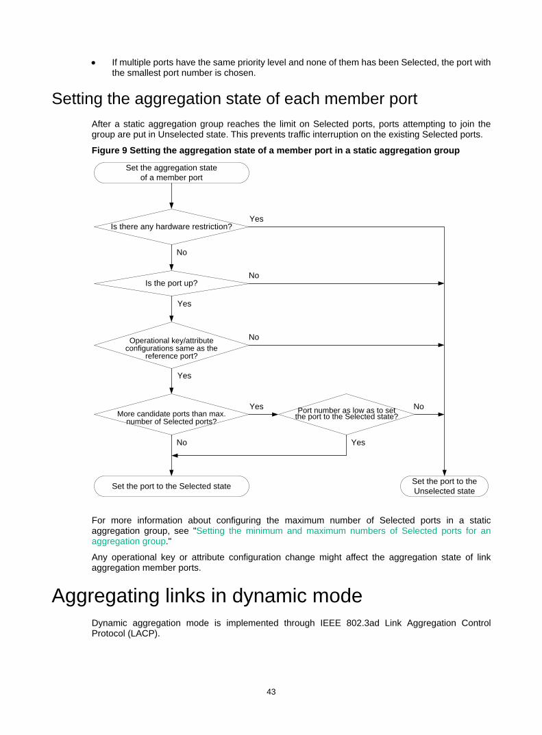
43
• If multiple ports have the same priority level and none of them has been Selected, the port with the smallest port number is chosen.
Setting the aggregation state of each member port After a static aggregation group reaches the limit on Selected ports, ports attempting to join the group are put in Unselected state. This prevents traffic interruption on the existing Selected ports.
Figure 9 Setting the aggregation state of a member port in a static aggregation group
For more information about configuring the maximum number of Selected ports in a static aggregation group, see "Setting the minimum and maximum numbers of Selected ports for an aggregation group."
Any operational key or attribute configuration change might affect the aggregation state of link aggregation member ports.
Aggregating links in dynamic mode Dynamic aggregation mode is implemented through IEEE 802.3ad Link Aggregation Control Protocol (LACP).
No
Operational key/attribute configurations same as the
reference port?
More candidate ports than max. number of Selected ports?
Is the port up?
Is there any hardware restriction?
Port number as low as to set the port to the Selected state?
Set the aggregation state of a member port
Set the port to the Selected state Set the port to the Unselected state
Yes
Yes
No
Yes
No
Yes
No Yes
No
44
LACP LACP uses LACPDUs to exchange aggregation information between LACP-enabled devices.
Each member port in an LACP-enabled aggregation group exchanges information with its peer. When a member port receives an LACPDU, it compares the received information with information received on the other member ports. In this way, the two systems reach an agreement on which ports are placed in the Selected state.
LACP functions LACP offers basic LACP functions and extended LACP functions, as described in Table 3.
Table 3 Basic and extended LACP functions
Category Description
Basic LACP functions Implemented through the basic LACPDU fields, including the system LACP priority, system MAC address, port priority, port number, and operational key.
Extended LACP functions
Implemented by extending the LACPDU with new TLV fields. This is how the LACP MAD mechanism of the IRF feature is implemented. The switch series can participate in LACP MAD as either an IRF member device or an intermediate device. For more information about IRF and the LACP MAD mechanism, see IRF Configuration Guide.
LACP operating modes LACP can operate in active mode or passive mode.
When LACP is operating in passive mode on a local member port and its peer port, both ports cannot send LACPDUs. When LACP is operating in active mode on the port on either end of a link, both ports can send LACPDUs.
LACP priorities LACP priorities include system LACP priority and port priority, as described in Table 4. The smaller the priority value, the higher the priority.
Table 4 LACP priorities
Type Description
System LACP priority
Used by two peer devices (or systems) to determine which one is superior in link aggregation. In dynamic link aggregation, the system that has higher system LACP priority sets the Selected state of member ports on its side. The system that has lower priority sets port state accordingly.
Port priority Determines the likelihood of a member port to be selected on a system. A port with a higher port priority is more likely to become Selected.
LACP timeout interval The LACP timeout interval specifies how long a member port waits to receive LACPDUs from the peer port. If a local member port does not receive LACPDUs from the peer within the LACP timeout interval, the member port considers the peer as failed.
The LACP timeout interval also determines the LACPDU sending rate of the peer. LACP timeout intervals include the following types: • Short timeout interval—3 seconds. If you use the short timeout interval, the peer sends one
LACPDU per second.
45
• Long timeout interval—90 seconds. If you use the long timeout interval, the peer sends one LACPDU every 30 seconds.
How dynamic link aggregation works Choosing a reference port
The system chooses a reference port from the member ports that are in up state and have the same attribute configurations as the aggregate interface. A Selected port must have the same operational key and attribute configurations as the reference port.
The local system (the actor) and the remote system (the partner) negotiate a reference port by using the following workflow: 1. The two systems compare their system IDs to determine the system with the smaller system ID.
A system ID contains the system LACP priority and the system MAC address. a. The two systems compare their LACP priority values.
The lower the LACP priority, the smaller the system ID. If LACP priority values are the same, the two systems proceed to step b.
b. The two systems compare their MAC addresses. The lower the MAC address, the smaller the system ID.
2. The system with the smaller system ID chooses the port with the smallest port ID as the reference port. A port ID contains a port priority and a port number. The lower the port priority, the smaller the port ID. a. The system chooses the port with the lowest priority value as the reference port.
If ports have the same priority, the system proceeds to step b. b. The system compares their port numbers.
The smaller the port number, the smaller the port ID. The port with the smallest port number and the same attribute configurations as the aggregate interface is chosen as the reference port.
Setting the aggregation state of each member port After the reference port is chosen, the system with the smaller system ID sets the state of each member port on its side.

46
Figure 10 Setting the state of a member port in a dynamic aggregation group
Meanwhile, the system with the higher system ID is aware of the aggregation state changes on the remote system. The system sets the aggregation state of local member ports the same as their peer ports.
When you aggregate interfaces in dynamic mode, follow these guidelines: • A dynamic link aggregation group preferably sets full-duplex ports as the Selected ports. The
group will set only one half-duplex port as a Selected port when either of the following conditions exist: None of the full-duplex ports can be chosen as Selected ports. Only half-duplex ports exist in the group.
• To ensure stable aggregation and service continuity, do not change the operational key or attribute configurations on any member port.
No
More candidate ports than allowed max. number of Selected ports?
Is the port up?
Is there any hardware restriction?
Port number as low as to set the port in Selected state?
Set the aggregation state of a member port
Set the port to the Selected state Set the port to the Unselected state
Yes
Yes
No
Yes
No
Yes
No Yes
No
Operational key/attribute configurations of the peer port same
as the peer port of the reference port?
Yes
No
Operational key/attribute configurations same as the
reference port?
47
• When the aggregation state of a local port changes in a dynamic aggregation group, the aggregation state of the peer port also changes.
• After the Selected port limit is reached, a newly joining port becomes a Selected port if it is more eligible than a current Selected port.
For more information about configuring the maximum number of Selected ports in a dynamic aggregation group, see "Setting the minimum and maximum numbers of Selected ports for an aggregation group."
Edge aggregate interface Dynamic link aggregation fails on a server-facing aggregate interface if dynamic link aggregation is configured only on the device. The device forwards traffic by using only one of the physical ports that are connected to the server.
To improve link reliability, configure the aggregate interface as an edge aggregate interface. This feature enables all member ports of the aggregation group to forward traffic. When a member port fails, its traffic is automatically switched to other member ports.
After dynamic link aggregation is configured on the server, the device can receive LACPDUs from the server. Then, link aggregation between the device and the server operates correctly.
An edge aggregate interface takes effect only when it is configured on an aggregate interface corresponding to a dynamic aggregation group.
Load sharing modes for link aggregation groups In a link aggregation group, traffic can be load shared across the Selected ports based on any of the following modes: • Per-flow load sharing—Load shares traffic on a per-flow basis. The load sharing mode
classifies packets into flows and forwards packets of the same flow on the same link. This mode can be one or any combination of the following criteria that classify traffic: Source or destination MAC address. Source or destination port number. Ingress port. Source or destination IP address.
• Packet type-based load sharing—Load shares traffic automatically based on packet types (Layer 2, IPv4, or IPv6 for example).
Ethernet link aggregation configuration task list Tasks at a glance (Required.) Configuring an aggregation group: • Configuring a Layer 2 aggregation group • Configuring a Layer 3 aggregation group • Configuring an S-channel bundle group
48
Tasks at a glance (Optional.) Configuring an aggregate interface: • Configuring the description of an aggregate interface • Specifying ignored VLANs for a Layer 2 aggregate interface • Setting the MTU for a Layer 3 aggregate interface • Setting the MAC address for a Layer 3 aggregate interface • Setting the minimum and maximum numbers of Selected ports for an aggregation group • Setting the expected bandwidth for an aggregate interface • Configuring an edge aggregate interface • Enabling BFD for an aggregation group • Shutting down an aggregate interface • Restoring the default settings for an aggregate interface
(Optional.) Configuring load balancing for link aggregation group: • Setting load sharing modes for link aggregation groups • Configuring the ignored fields for the default load sharing mode • Enabling local-first load sharing for link aggregation • Configuring per-flow load sharing algorithm settings for Ethernet link aggregation • Setting the global load sharing mode for MAC-in-MAC traffic
Enabling link-aggregation traffic redirection
(Optional.) Specifying link aggregation management VLANs and management port
(Optional.) Specifying a link aggregation management subnet
Configuring an aggregation group This section explains how to configure an aggregation group.
Configuration restrictions and guidelines When you configure an aggregation group, follow these restrictions and guidelines: • You cannot assign a port to a Layer 2 aggregation group if any of the following features are
configured on the port: MAC authentication (see Security Configuration Guide). Port security (see Security Configuration Guide). 802.1X (see Security Configuration Guide). Association between AC and cross connection (see MPLS Configuration Guide). AC-VSI association (see MPLS Configuration Guide).
• You cannot assign a port to a Layer 3 aggregation group if any of the following features are configured on the port: Association between AC and cross connection (see MPLS Configuration Guide). AC-VSI association (see MPLS Configuration Guide).
• If a port is used as a reflector port for port mirroring, do not assign it to an aggregation group. For more information about reflector ports, see Network Management and Monitoring Configuration Guide.
• Removing an aggregate interface also removes its aggregation group and causes all member ports to leave the aggregation group.
• You must configure the same aggregation mode on the two ends of an aggregate link.
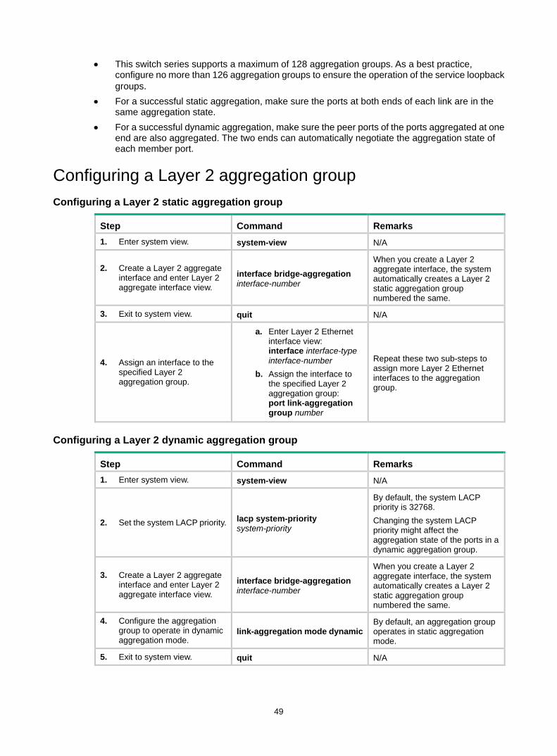
49
• This switch series supports a maximum of 128 aggregation groups. As a best practice, configure no more than 126 aggregation groups to ensure the operation of the service loopback groups.
• For a successful static aggregation, make sure the ports at both ends of each link are in the same aggregation state.
• For a successful dynamic aggregation, make sure the peer ports of the ports aggregated at one end are also aggregated. The two ends can automatically negotiate the aggregation state of each member port.
Configuring a Layer 2 aggregation group Configuring a Layer 2 static aggregation group
Step Command Remarks 1. Enter system view. system-view N/A
2. Create a Layer 2 aggregate interface and enter Layer 2 aggregate interface view.
interface bridge-aggregation interface-number
When you create a Layer 2 aggregate interface, the system automatically creates a Layer 2 static aggregation group numbered the same.
3. Exit to system view. quit N/A
4. Assign an interface to the specified Layer 2 aggregation group.
a. Enter Layer 2 Ethernet interface view: interface interface-type interface-number
b. Assign the interface to the specified Layer 2 aggregation group: port link-aggregation group number
Repeat these two sub-steps to assign more Layer 2 Ethernet interfaces to the aggregation group.
Configuring a Layer 2 dynamic aggregation group
Step Command Remarks 1. Enter system view. system-view N/A
2. Set the system LACP priority. lacp system-priority system-priority
By default, the system LACP priority is 32768. Changing the system LACP priority might affect the aggregation state of the ports in a dynamic aggregation group.
3. Create a Layer 2 aggregate interface and enter Layer 2 aggregate interface view.
interface bridge-aggregation interface-number
When you create a Layer 2 aggregate interface, the system automatically creates a Layer 2 static aggregation group numbered the same.
4. Configure the aggregation group to operate in dynamic aggregation mode.
link-aggregation mode dynamic By default, an aggregation group operates in static aggregation mode.
5. Exit to system view. quit N/A
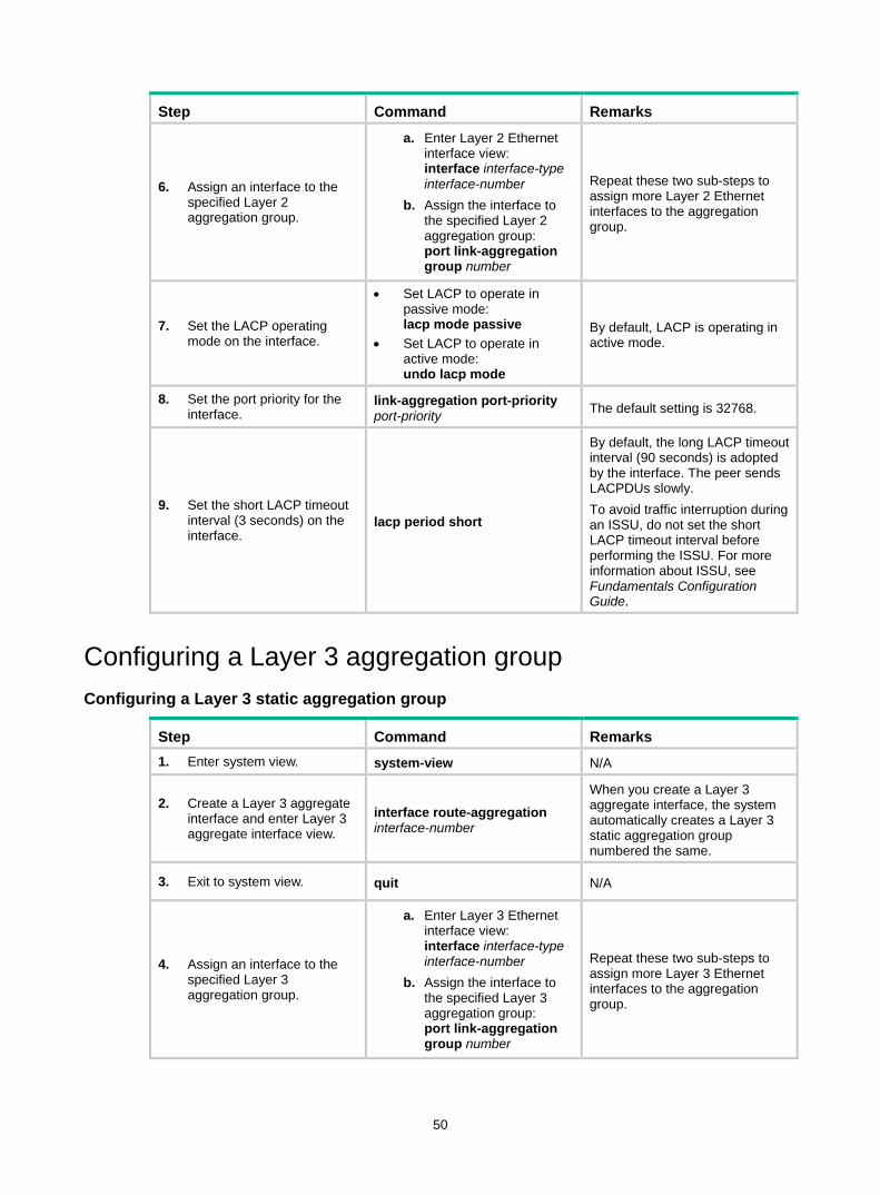
50
Step Command Remarks
6. Assign an interface to the specified Layer 2 aggregation group.
a. Enter Layer 2 Ethernet interface view: interface interface-type interface-number
b. Assign the interface to the specified Layer 2 aggregation group: port link-aggregation group number
Repeat these two sub-steps to assign more Layer 2 Ethernet interfaces to the aggregation group.
7. Set the LACP operating mode on the interface.
• Set LACP to operate in passive mode: lacp mode passive
• Set LACP to operate in active mode: undo lacp mode
By default, LACP is operating in active mode.
8. Set the port priority for the interface.
link-aggregation port-priority port-priority The default setting is 32768.
9. Set the short LACP timeout interval (3 seconds) on the interface.
lacp period short
By default, the long LACP timeout interval (90 seconds) is adopted by the interface. The peer sends LACPDUs slowly. To avoid traffic interruption during an ISSU, do not set the short LACP timeout interval before performing the ISSU. For more information about ISSU, see Fundamentals Configuration Guide.
Configuring a Layer 3 aggregation group Configuring a Layer 3 static aggregation group
Step Command Remarks 1. Enter system view. system-view N/A
2. Create a Layer 3 aggregate interface and enter Layer 3 aggregate interface view.
interface route-aggregation interface-number
When you create a Layer 3 aggregate interface, the system automatically creates a Layer 3 static aggregation group numbered the same.
3. Exit to system view. quit N/A
4. Assign an interface to the specified Layer 3 aggregation group.
a. Enter Layer 3 Ethernet interface view: interface interface-type interface-number
b. Assign the interface to the specified Layer 3 aggregation group: port link-aggregation group number
Repeat these two sub-steps to assign more Layer 3 Ethernet interfaces to the aggregation group.
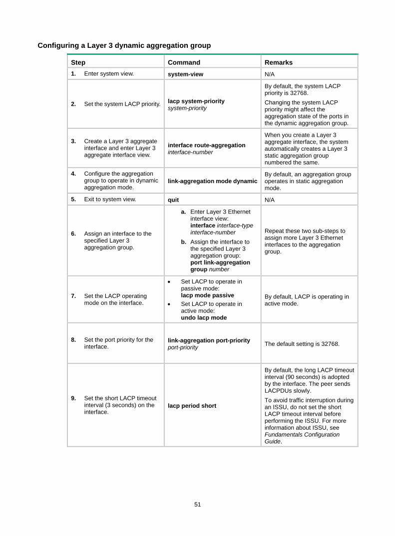
51
Configuring a Layer 3 dynamic aggregation group
Step Command Remarks 1. Enter system view. system-view N/A
2. Set the system LACP priority. lacp system-priority system-priority
By default, the system LACP priority is 32768. Changing the system LACP priority might affect the aggregation state of the ports in the dynamic aggregation group.
3. Create a Layer 3 aggregate interface and enter Layer 3 aggregate interface view.
interface route-aggregation interface-number
When you create a Layer 3 aggregate interface, the system automatically creates a Layer 3 static aggregation group numbered the same.
4. Configure the aggregation group to operate in dynamic aggregation mode.
link-aggregation mode dynamic By default, an aggregation group operates in static aggregation mode.
5. Exit to system view. quit N/A
6. Assign an interface to the specified Layer 3 aggregation group.
a. Enter Layer 3 Ethernet interface view: interface interface-type interface-number
b. Assign the interface to the specified Layer 3 aggregation group: port link-aggregation group number
Repeat these two sub-steps to assign more Layer 3 Ethernet interfaces to the aggregation group.
7. Set the LACP operating mode on the interface.
• Set LACP to operate in passive mode: lacp mode passive
• Set LACP to operate in active mode: undo lacp mode
By default, LACP is operating in active mode.
8. Set the port priority for the interface.
link-aggregation port-priority port-priority The default setting is 32768.
9. Set the short LACP timeout interval (3 seconds) on the interface.
lacp period short
By default, the long LACP timeout interval (90 seconds) is adopted by the interface. The peer sends LACPDUs slowly. To avoid traffic interruption during an ISSU, do not set the short LACP timeout interval before performing the ISSU. For more information about ISSU, see Fundamentals Configuration Guide.
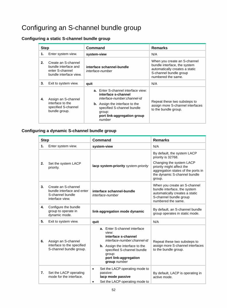
52
Configuring an S-channel bundle group Configuring a static S-channel bundle group
Step Command Remarks 1. Enter system view. system-view N/A
2. Create an S-channel bundle interface and enter S-channel bundle interface view.
interface schannel-bundle interface-number
When you create an S-channel bundle interface, the system automatically creates a static S-channel bundle group numbered the same.
3. Exit to system view. quit N/A
4. Assign an S-channel interface to the specified S-channel bundle group.
a. Enter S-channel interface view: interface s-channel interface-number:channel-id
b. Assign the interface to the specified S-channel bundle group: port link-aggregation group number
Repeat these two substeps to assign more S-channel interfaces to the bundle group.
Configuring a dynamic S-channel bundle group
Step Command Remarks 1. Enter system view. system-view N/A
2. Set the system LACP priority. lacp system-priority system-priority
By default, the system LACP priority is 32768. Changing the system LACP priority might affect the aggregation states of the ports in the dynamic S-channel bundle group.
3. Create an S-channel bundle interface and enter S-channel bundle interface view.
interface schannel-bundle interface-number
When you create an S-channel bundle interface, the system automatically creates a static S-channel bundle group numbered the same.
4. Configure the bundle group to operate in dynamic mode.
link-aggregation mode dynamic By default, an S-channel bundle group operates in static mode.
5. Exit to system view. quit N/A
6. Assign an S-channel interface to the specified S-channel bundle group.
a. Enter S-channel interface view: interface s-channel interface-number:channel-id
b. Assign the interface to the specified S-channel bundle group: port link-aggregation group number
Repeat these two substeps to assign more S-channel interfaces to the bundle group.
7. Set the LACP operating mode for the interface.
• Set the LACP operating mode to passive: lacp mode passive
• Set the LACP operating mode to
By default, LACP is operating in active mode.
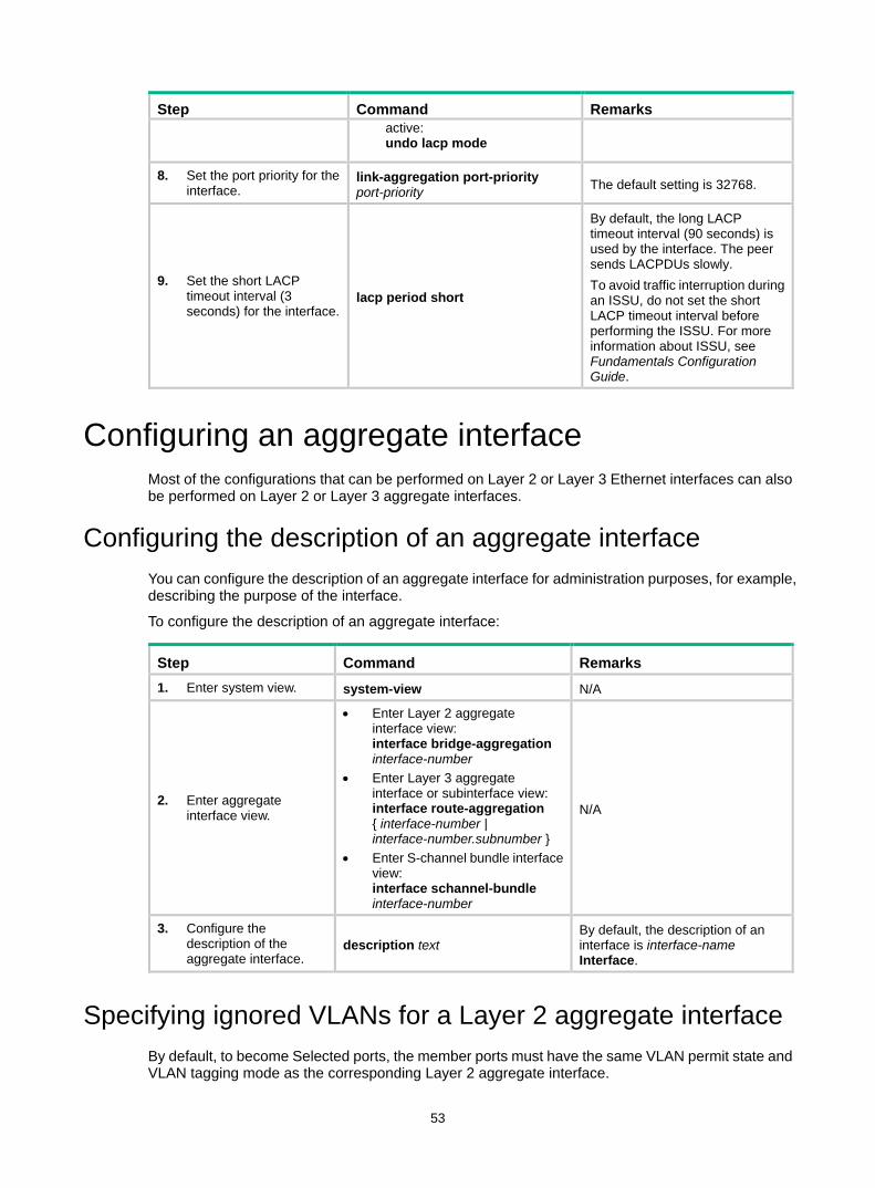
53
Step Command Remarks active: undo lacp mode
8. Set the port priority for the interface.
link-aggregation port-priority port-priority The default setting is 32768.
9. Set the short LACP timeout interval (3 seconds) for the interface.
lacp period short
By default, the long LACP timeout interval (90 seconds) is used by the interface. The peer sends LACPDUs slowly. To avoid traffic interruption during an ISSU, do not set the short LACP timeout interval before performing the ISSU. For more information about ISSU, see Fundamentals Configuration Guide.
Configuring an aggregate interface Most of the configurations that can be performed on Layer 2 or Layer 3 Ethernet interfaces can also be performed on Layer 2 or Layer 3 aggregate interfaces.
Configuring the description of an aggregate interface You can configure the description of an aggregate interface for administration purposes, for example, describing the purpose of the interface.
To configure the description of an aggregate interface:
Step Command Remarks 1. Enter system view. system-view N/A
2. Enter aggregate interface view.
• Enter Layer 2 aggregate interface view: interface bridge-aggregation interface-number
• Enter Layer 3 aggregate interface or subinterface view: interface route-aggregation { interface-number | interface-number.subnumber }
• Enter S-channel bundle interface view: interface schannel-bundle interface-number
N/A
3. Configure the description of the aggregate interface.
description text By default, the description of an interface is interface-name Interface.
Specifying ignored VLANs for a Layer 2 aggregate interface By default, to become Selected ports, the member ports must have the same VLAN permit state and VLAN tagging mode as the corresponding Layer 2 aggregate interface.
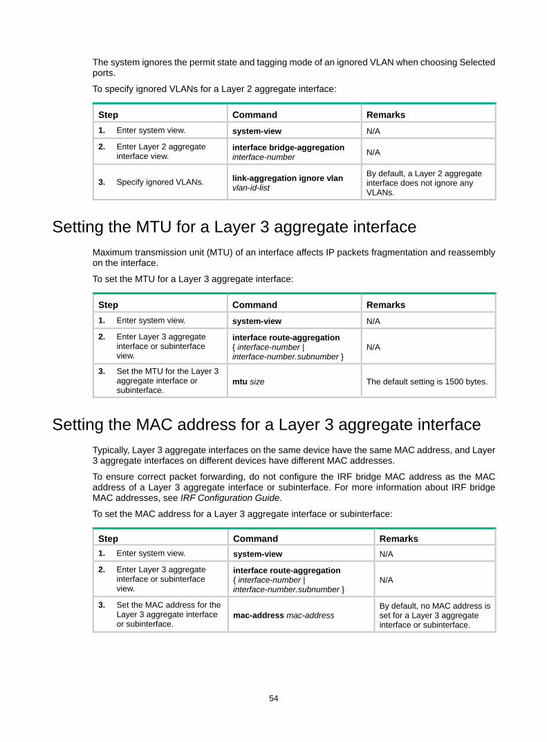
54
The system ignores the permit state and tagging mode of an ignored VLAN when choosing Selected ports.
To specify ignored VLANs for a Layer 2 aggregate interface:
Step Command Remarks 1. Enter system view. system-view N/A
2. Enter Layer 2 aggregate interface view.
interface bridge-aggregation interface-number N/A
3. Specify ignored VLANs. link-aggregation ignore vlan vlan-id-list
By default, a Layer 2 aggregate interface does not ignore any VLANs.
Setting the MTU for a Layer 3 aggregate interface Maximum transmission unit (MTU) of an interface affects IP packets fragmentation and reassembly on the interface.
To set the MTU for a Layer 3 aggregate interface:
Step Command Remarks 1. Enter system view. system-view N/A
2. Enter Layer 3 aggregate interface or subinterface view.
interface route-aggregation { interface-number | interface-number.subnumber }
N/A
3. Set the MTU for the Layer 3 aggregate interface or subinterface.
mtu size The default setting is 1500 bytes.
Setting the MAC address for a Layer 3 aggregate interface Typically, Layer 3 aggregate interfaces on the same device have the same MAC address, and Layer 3 aggregate interfaces on different devices have different MAC addresses.
To ensure correct packet forwarding, do not configure the IRF bridge MAC address as the MAC address of a Layer 3 aggregate interface or subinterface. For more information about IRF bridge MAC addresses, see IRF Configuration Guide.
To set the MAC address for a Layer 3 aggregate interface or subinterface:
Step Command Remarks 1. Enter system view. system-view N/A
2. Enter Layer 3 aggregate interface or subinterface view.
interface route-aggregation { interface-number | interface-number.subnumber }
N/A
3. Set the MAC address for the Layer 3 aggregate interface or subinterface.
mac-address mac-address By default, no MAC address is set for a Layer 3 aggregate interface or subinterface.
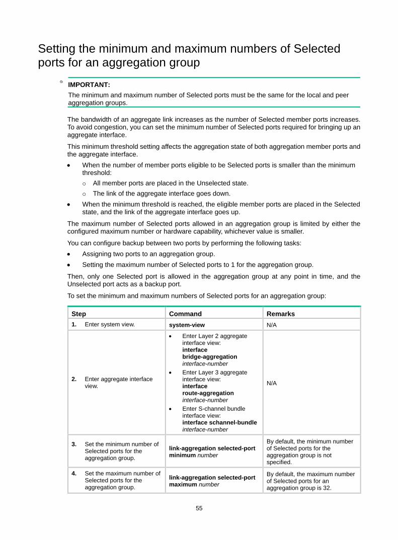
55
Setting the minimum and maximum numbers of Selected ports for an aggregation group
IMPORTANT: The minimum and maximum number of Selected ports must be the same for the local and peer aggregation groups.
The bandwidth of an aggregate link increases as the number of Selected member ports increases. To avoid congestion, you can set the minimum number of Selected ports required for bringing up an aggregate interface.
This minimum threshold setting affects the aggregation state of both aggregation member ports and the aggregate interface. • When the number of member ports eligible to be Selected ports is smaller than the minimum
threshold: All member ports are placed in the Unselected state. The link of the aggregate interface goes down.
• When the minimum threshold is reached, the eligible member ports are placed in the Selected state, and the link of the aggregate interface goes up.
The maximum number of Selected ports allowed in an aggregation group is limited by either the configured maximum number or hardware capability, whichever value is smaller.
You can configure backup between two ports by performing the following tasks: • Assigning two ports to an aggregation group. • Setting the maximum number of Selected ports to 1 for the aggregation group.
Then, only one Selected port is allowed in the aggregation group at any point in time, and the Unselected port acts as a backup port.
To set the minimum and maximum numbers of Selected ports for an aggregation group:
Step Command Remarks 1. Enter system view. system-view N/A
2. Enter aggregate interface view.
• Enter Layer 2 aggregate interface view: interface bridge-aggregation interface-number
• Enter Layer 3 aggregate interface view: interface route-aggregation interface-number
• Enter S-channel bundle interface view: interface schannel-bundle interface-number
N/A
3. Set the minimum number of Selected ports for the aggregation group.
link-aggregation selected-port minimum number
By default, the minimum number of Selected ports for the aggregation group is not specified.
4. Set the maximum number of Selected ports for the aggregation group.
link-aggregation selected-port maximum number
By default, the maximum number of Selected ports for an aggregation group is 32.
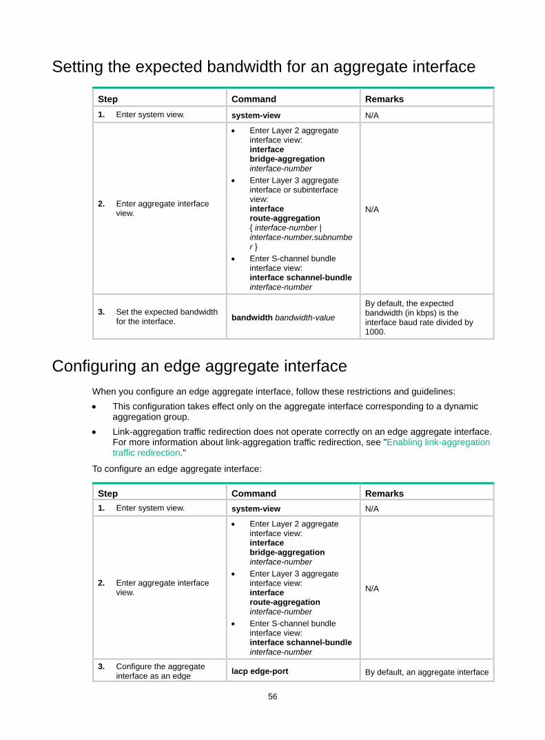
56
Setting the expected bandwidth for an aggregate interface
Step Command Remarks 1. Enter system view. system-view N/A
2. Enter aggregate interface view.
• Enter Layer 2 aggregate interface view: interface bridge-aggregation interface-number
• Enter Layer 3 aggregate interface or subinterface view: interface route-aggregation { interface-number | interface-number.subnumber }
• Enter S-channel bundle interface view: interface schannel-bundle interface-number
N/A
3. Set the expected bandwidth for the interface. bandwidth bandwidth-value
By default, the expected bandwidth (in kbps) is the interface baud rate divided by 1000.
Configuring an edge aggregate interface When you configure an edge aggregate interface, follow these restrictions and guidelines: • This configuration takes effect only on the aggregate interface corresponding to a dynamic
aggregation group. • Link-aggregation traffic redirection does not operate correctly on an edge aggregate interface.
For more information about link-aggregation traffic redirection, see "Enabling link-aggregation traffic redirection."
To configure an edge aggregate interface:
Step Command Remarks 1. Enter system view. system-view N/A
2. Enter aggregate interface view.
• Enter Layer 2 aggregate interface view: interface bridge-aggregation interface-number
• Enter Layer 3 aggregate interface view: interface route-aggregation interface-number
• Enter S-channel bundle interface view: interface schannel-bundle interface-number
N/A
3. Configure the aggregate interface as an edge lacp edge-port By default, an aggregate interface
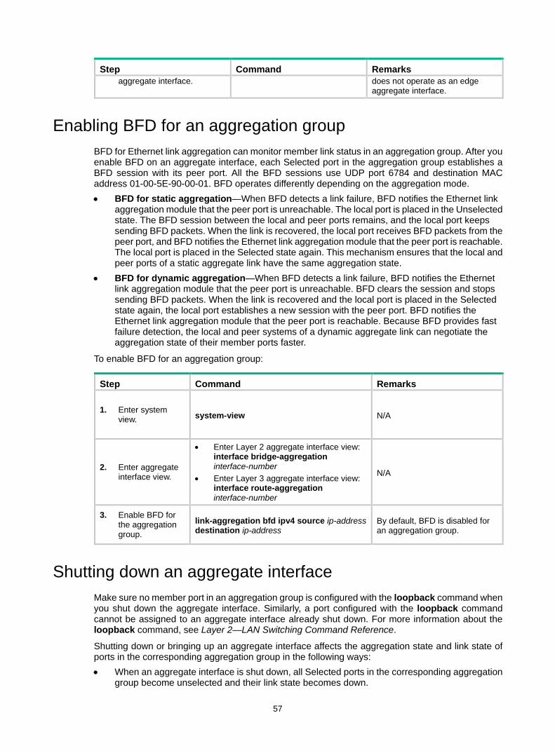
57
Step Command Remarks aggregate interface. does not operate as an edge
aggregate interface.
Enabling BFD for an aggregation group BFD for Ethernet link aggregation can monitor member link status in an aggregation group. After you enable BFD on an aggregate interface, each Selected port in the aggregation group establishes a BFD session with its peer port. All the BFD sessions use UDP port 6784 and destination MAC address 01-00-5E-90-00-01. BFD operates differently depending on the aggregation mode. • BFD for static aggregation—When BFD detects a link failure, BFD notifies the Ethernet link
aggregation module that the peer port is unreachable. The local port is placed in the Unselected state. The BFD session between the local and peer ports remains, and the local port keeps sending BFD packets. When the link is recovered, the local port receives BFD packets from the peer port, and BFD notifies the Ethernet link aggregation module that the peer port is reachable. The local port is placed in the Selected state again. This mechanism ensures that the local and peer ports of a static aggregate link have the same aggregation state.
• BFD for dynamic aggregation—When BFD detects a link failure, BFD notifies the Ethernet link aggregation module that the peer port is unreachable. BFD clears the session and stops sending BFD packets. When the link is recovered and the local port is placed in the Selected state again, the local port establishes a new session with the peer port. BFD notifies the Ethernet link aggregation module that the peer port is reachable. Because BFD provides fast failure detection, the local and peer systems of a dynamic aggregate link can negotiate the aggregation state of their member ports faster.
To enable BFD for an aggregation group:
Step Command Remarks
1. Enter system view. system-view N/A
2. Enter aggregate interface view.
• Enter Layer 2 aggregate interface view: interface bridge-aggregation interface-number
• Enter Layer 3 aggregate interface view: interface route-aggregation interface-number
N/A
3. Enable BFD for the aggregation group.
link-aggregation bfd ipv4 source ip-address destination ip-address
By default, BFD is disabled for an aggregation group.
Shutting down an aggregate interface Make sure no member port in an aggregation group is configured with the loopback command when you shut down the aggregate interface. Similarly, a port configured with the loopback command cannot be assigned to an aggregate interface already shut down. For more information about the loopback command, see Layer 2—LAN Switching Command Reference.
Shutting down or bringing up an aggregate interface affects the aggregation state and link state of ports in the corresponding aggregation group in the following ways: • When an aggregate interface is shut down, all Selected ports in the corresponding aggregation
group become unselected and their link state becomes down.
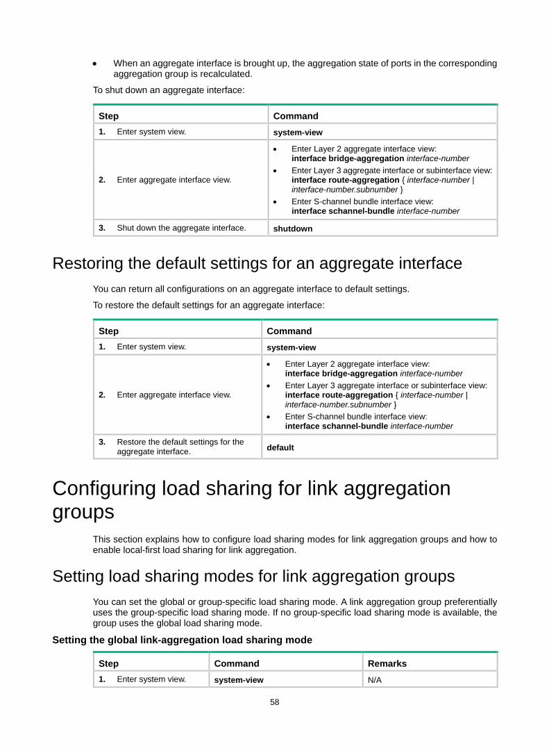
58
• When an aggregate interface is brought up, the aggregation state of ports in the corresponding aggregation group is recalculated.
To shut down an aggregate interface:
Step Command 1. Enter system view. system-view
2. Enter aggregate interface view.
• Enter Layer 2 aggregate interface view: interface bridge-aggregation interface-number
• Enter Layer 3 aggregate interface or subinterface view: interface route-aggregation { interface-number | interface-number.subnumber }
• Enter S-channel bundle interface view: interface schannel-bundle interface-number
3. Shut down the aggregate interface. shutdown
Restoring the default settings for an aggregate interface You can return all configurations on an aggregate interface to default settings.
To restore the default settings for an aggregate interface:
Step Command 1. Enter system view. system-view
2. Enter aggregate interface view.
• Enter Layer 2 aggregate interface view: interface bridge-aggregation interface-number
• Enter Layer 3 aggregate interface or subinterface view: interface route-aggregation { interface-number | interface-number.subnumber }
• Enter S-channel bundle interface view: interface schannel-bundle interface-number
3. Restore the default settings for the aggregate interface. default
Configuring load sharing for link aggregation groups
This section explains how to configure load sharing modes for link aggregation groups and how to enable local-first load sharing for link aggregation.
Setting load sharing modes for link aggregation groups You can set the global or group-specific load sharing mode. A link aggregation group preferentially uses the group-specific load sharing mode. If no group-specific load sharing mode is available, the group uses the global load sharing mode.
Setting the global link-aggregation load sharing mode
Step Command Remarks 1. Enter system view. system-view N/A
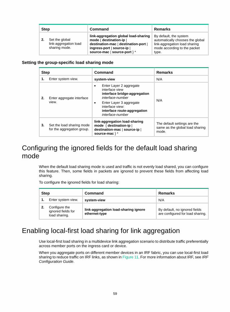
59
Step Command Remarks
2. Set the global link-aggregation load sharing mode.
link-aggregation global load-sharing mode { destination-ip | destination-mac | destination-port | ingress-port | source-ip | source-mac | source-port } *
By default, the system automatically chooses the global link-aggregation load sharing mode according to the packet type.
Setting the group-specific load sharing mode
Step Command Remarks 1. Enter system view. system-view N/A
2. Enter aggregate interface view.
• Enter Layer 2 aggregate interface view interface bridge-aggregation interface-number
• Enter Layer 3 aggregate interface view: interface route-aggregation interface-number
N/A
3. Set the load sharing mode for the aggregation group.
link-aggregation load-sharing mode { destination-ip | destination-mac | source-ip | source-mac } *
The default settings are the same as the global load sharing mode.
Configuring the ignored fields for the default load sharing mode
When the default load sharing mode is used and traffic is not evenly load shared, you can configure this feature. Then, some fields in packets are ignored to prevent these fields from affecting load sharing.
To configure the ignored fields for load sharing:
Step Command Remarks 1. Enter system view. system-view N/A
2. Configure the ignored fields for load sharing.
link-aggregation load-sharing ignore ethernet-type
By default, no ignored fields are configured for load sharing.
Enabling local-first load sharing for link aggregation Use local-first load sharing in a multidevice link aggregation scenario to distribute traffic preferentially across member ports on the ingress card or device.
When you aggregate ports on different member devices in an IRF fabric, you can use local-first load sharing to reduce traffic on IRF links, as shown in Figure 11. For more information about IRF, see IRF Configuration Guide.

60
Figure 11 Load sharing for multiswitch link aggregation in an IRF fabric
To enable local-first load sharing for link aggregation:
Step Command Remarks 1. Enter system view. system-view N/A
2. Enable local-first load sharing for link aggregation.
link-aggregation load-sharing mode local-first
By default, local-first load sharing for link aggregation is enabled.
Configuring per-flow load sharing algorithm settings for Ethernet link aggregation
Configure the per-flow load sharing algorithm and algorithm seed to optimize traffic distribution on aggregate links based on existing per-flow load sharing settings. You can set only the algorithm or the algorithm seed, or both. You can combine an algorithm with different algorithm seeds to obtain different effects.
This feature does not take effect on per-flow load sharing that uses the following traffic classification criteria: • Source IP address. • Destination IP address. • Source MAC address. • Destination MAC address. • Source and destination IP addresses. • Source and destination MAC addresses.
To configure per-flow load sharing algorithm settings for Ethernet link aggregation:
Any Selected ports on the ingress switch?
Local-first load sharing mechanism enabled?
Yes No
Yes
No
The egress port for a traffic flow is an aggregate interface that has Selected
ports on different IRF member switches
Packets are load shared only across the Selected ports on the
ingress switch
Packets are load shared across all Selected ports

61
Step Command Remarks 1. Enter system view. system-view N/A
2. Configure the load sharing algorithm.
link-aggregation global load-sharing algorithm algorithm-number
By default, algorithm 0 is used. If the device fails to load share traffic flows across all Selected ports, you can specify algorithm 1 to 8 in sequence until the problem is solved.
3. Configure the load sharing algorithm seed.
link-aggregation global load-sharing seed seed-number
By default, algorithm seed 0 is used.
Setting the global load sharing mode for MAC-in-MAC traffic This feature sets the global load sharing mode for MAC-in-MAC traffic on the aggregate links of a backbone core bridge. For more information about backbone core bridges, see "Configuring PBB."
MAC-in-MAC traffic can be load shared based on any of the following items: • The outer frame header, and source and destination ports. • The inner frame header, and source and destination ports.
To set the global load sharing mode for MAC-in-MAC traffic:
Step Command Remarks 1. Enter system view. system-view N/A
2. Set the global load sharing mode for MAC-in-MAC traffic.
link-aggregation global load-sharing minm { inner | outer }
By default, MAC-in-MAC traffic is load shared based on the inner frame header, and source and destination ports.
Enabling link-aggregation traffic redirection Link-aggregation traffic redirection prevents traffic interruption.
When you shut down a Selected port in an aggregation group, this feature redirects traffic to other Selected ports.
When you restart an IRF member device that contains Selected ports, this feature redirects traffic to other IRF member devices.
You can enable link-aggregation traffic redirection globally or for an aggregation group. Global link-aggregation traffic redirection settings take effect on all aggregation groups. A link aggregation group preferentially uses the group-specific link-aggregation traffic redirection settings. If group-specific link-aggregation traffic redirection is not configured, the group uses the global link-aggregation traffic redirection settings.
Configuration restrictions and guidelines When you enable ink-aggregation traffic redirection, follow these restrictions and guidelines: • Link-aggregation traffic redirection applies only to dynamic link aggregation groups and takes
effect on only known unicast packets. • To prevent traffic interruption, enable link-aggregation traffic redirection on devices at both ends
of the aggregate link.

62
• To prevent packet loss that might occur at a reboot, do not enable spanning tree together with link-aggregation traffic redirection.
• Link-aggregation traffic redirection does not operate correctly on an edge aggregate interface. • As a best practice, enable link-aggregation traffic redirection on aggregate interfaces. If you
enable this feature globally, communication with a third-party peer device might be affected if the peer is not compatible with this feature.
Configuration procedure To enable link-aggregation traffic redirection globally:
Step Command Remarks 1. Enter system view. system-view N/A
2. Enable link-aggregation traffic redirection globally.
link-aggregation lacp traffic-redirect-notification enable
By default, link-aggregation traffic redirection is disabled globally.
To enable link-aggregation traffic redirection for an aggregation group:
Step Command Remarks 1. Enter system view. system-view N/A
2. Enter aggregate interface view.
• Enter Layer 2 aggregate interface view: interface bridge-aggregation interface-number
• Enter Layer 3 aggregate interface view: interface route-aggregation interface-number
N/A
3. Enable link-aggregation traffic redirection for the aggregation group.
link-aggregation lacp traffic-redirect-notification enable
By default, link-aggregation traffic redirection is disabled for an aggregation group.
Specifying link aggregation management VLANs and management port
For an aggregation group to forward traffic of some VLANs through a specific port, specify the VLANs as management VLANs and the port as a management port.
Do not use the display link-aggregation load-sharing path command to identify the outgoing port for the traffic in a management VLAN. This command calculates the outgoing port for a traffic flow based on the algorithm for the specified load sharing mode. The outgoing port output from this command for management VLAN traffic might not be the management port (the actual outgoing port).
To specify link aggregation management VLANs and management port for an aggregation group:
Step Command Remarks 1. Enter system view. system-view N/A
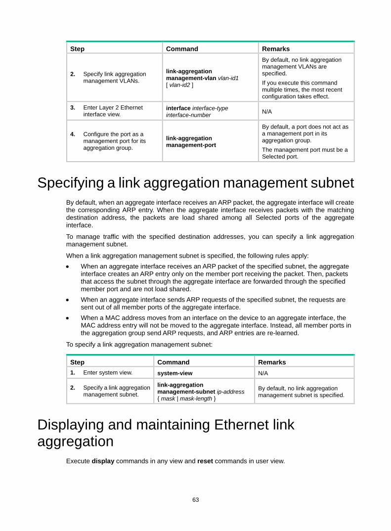
63
Step Command Remarks
2. Specify link aggregation management VLANs.
link-aggregation management-vlan vlan-id1 [ vlan-id2 ]
By default, no link aggregation management VLANs are specified. If you execute this command multiple times, the most recent configuration takes effect.
3. Enter Layer 2 Ethernet interface view.
interface interface-type interface-number N/A
4. Configure the port as a management port for its aggregation group.
link-aggregation management-port
By default, a port does not act as a management port in its aggregation group. The management port must be a Selected port.
Specifying a link aggregation management subnet By default, when an aggregate interface receives an ARP packet, the aggregate interface will create the corresponding ARP entry. When the aggregate interface receives packets with the matching destination address, the packets are load shared among all Selected ports of the aggregate interface.
To manage traffic with the specified destination addresses, you can specify a link aggregation management subnet.
When a link aggregation management subnet is specified, the following rules apply: • When an aggregate interface receives an ARP packet of the specified subnet, the aggregate
interface creates an ARP entry only on the member port receiving the packet. Then, packets that access the subnet through the aggregate interface are forwarded through the specified member port and are not load shared.
• When an aggregate interface sends ARP requests of the specified subnet, the requests are sent out of all member ports of the aggregate interface.
• When a MAC address moves from an interface on the device to an aggregate interface, the MAC address entry will not be moved to the aggregate interface. Instead, all member ports in the aggregation group send ARP requests, and ARP entries are re-learned.
To specify a link aggregation management subnet:
Step Command Remarks 1. Enter system view. system-view N/A
2. Specify a link aggregation management subnet.
link-aggregation management-subnet ip-address { mask | mask-length }
By default, no link aggregation management subnet is specified.
Displaying and maintaining Ethernet link aggregation
Execute display commands in any view and reset commands in user view.
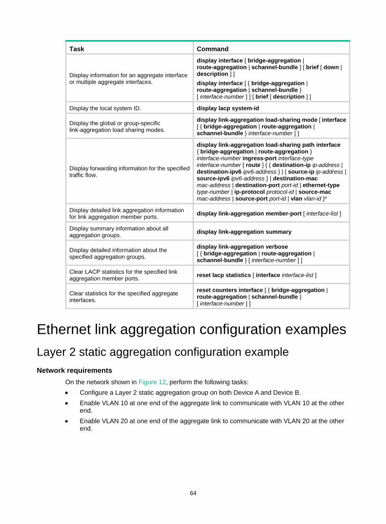
64
Task Command
Display information for an aggregate interface or multiple aggregate interfaces.
display interface [ bridge-aggregation | route-aggregation | schannel-bundle ] [ brief [ down | description ] ] display interface [ { bridge-aggregation | route-aggregation | schannel-bundle } [ interface-number ] ] [ brief [ description ] ]
Display the local system ID. display lacp system-id
Display the global or group-specific link-aggregation load sharing modes.
display link-aggregation load-sharing mode [ interface [ { bridge-aggregation | route-aggregation | schannel-bundle } interface-number ] ]
Display forwarding information for the specified traffic flow.
display link-aggregation load-sharing path interface { bridge-aggregation | route-aggregation } interface-number ingress-port interface-type interface-number [ route ] { { destination-ip ip-address | destination-ipv6 ipv6-address } | { source-ip ip-address | source-ipv6 ipv6-address } | destination-mac mac-address | destination-port port-id | ethernet-type type-number | ip-protocol protocol-id | source-mac mac-address | source-port port-id | vlan vlan-id }*
Display detailed link aggregation information for link aggregation member ports. display link-aggregation member-port [ interface-list ]
Display summary information about all aggregation groups. display link-aggregation summary
Display detailed information about the specified aggregation groups.
display link-aggregation verbose [ { bridge-aggregation | route-aggregation | schannel-bundle } [ interface-number ] ]
Clear LACP statistics for the specified link aggregation member ports. reset lacp statistics [ interface interface-list ]
Clear statistics for the specified aggregate interfaces.
reset counters interface [ { bridge-aggregation | route-aggregation | schannel-bundle } [ interface-number ] ]
Ethernet link aggregation configuration examples Layer 2 static aggregation configuration example Network requirements
On the network shown in Figure 12, perform the following tasks: • Configure a Layer 2 static aggregation group on both Device A and Device B. • Enable VLAN 10 at one end of the aggregate link to communicate with VLAN 10 at the other
end. • Enable VLAN 20 at one end of the aggregate link to communicate with VLAN 20 at the other
end.
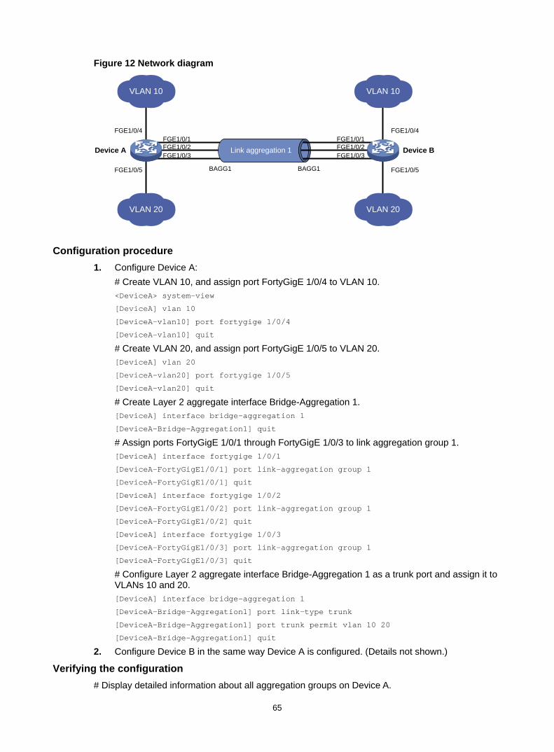
65
Figure 12 Network diagram
Configuration procedure 1. Configure Device A:
# Create VLAN 10, and assign port FortyGigE 1/0/4 to VLAN 10. <DeviceA> system-view
[DeviceA] vlan 10
[DeviceA-vlan10] port fortygige 1/0/4
[DeviceA-vlan10] quit
# Create VLAN 20, and assign port FortyGigE 1/0/5 to VLAN 20. [DeviceA] vlan 20
[DeviceA-vlan20] port fortygige 1/0/5
[DeviceA-vlan20] quit
# Create Layer 2 aggregate interface Bridge-Aggregation 1. [DeviceA] interface bridge-aggregation 1
[DeviceA-Bridge-Aggregation1] quit
# Assign ports FortyGigE 1/0/1 through FortyGigE 1/0/3 to link aggregation group 1. [DeviceA] interface fortygige 1/0/1
[DeviceA-FortyGigE1/0/1] port link-aggregation group 1
[DeviceA-FortyGigE1/0/1] quit
[DeviceA] interface fortygige 1/0/2
[DeviceA-FortyGigE1/0/2] port link-aggregation group 1
[DeviceA-FortyGigE1/0/2] quit
[DeviceA] interface fortygige 1/0/3
[DeviceA-FortyGigE1/0/3] port link-aggregation group 1
[DeviceA-FortyGigE1/0/3] quit
# Configure Layer 2 aggregate interface Bridge-Aggregation 1 as a trunk port and assign it to VLANs 10 and 20. [DeviceA] interface bridge-aggregation 1
[DeviceA-Bridge-Aggregation1] port link-type trunk
[DeviceA-Bridge-Aggregation1] port trunk permit vlan 10 20
[DeviceA-Bridge-Aggregation1] quit
2. Configure Device B in the same way Device A is configured. (Details not shown.)
Verifying the configuration # Display detailed information about all aggregation groups on Device A.
FGE1/0/1
Link aggregation 1
BAGG1 BAGG1
Device A Device B
VLAN 10
VLAN 20
FGE1/0/4
FGE1/0/5
VLAN 10
VLAN 20
FGE1/0/2FGE1/0/3
FGE1/0/1FGE1/0/4
FGE1/0/5
FGE1/0/2FGE1/0/3
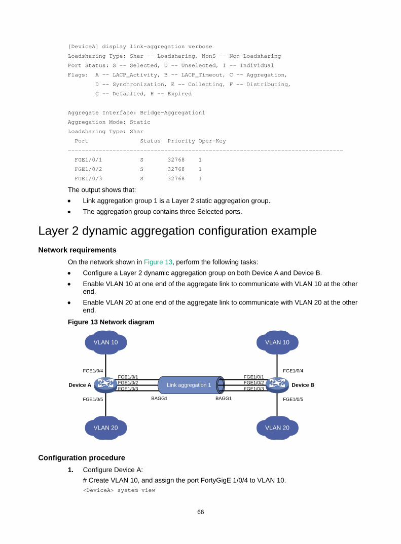
66
[DeviceA] display link-aggregation verbose
Loadsharing Type: Shar -- Loadsharing, NonS -- Non-Loadsharing
Port Status: S -- Selected, U -- Unselected, I -- Individual
Flags: A -- LACP_Activity, B -- LACP_Timeout, C -- Aggregation,
D -- Synchronization, E -- Collecting, F -- Distributing,
G -- Defaulted, H -- Expired
Aggregate Interface: Bridge-Aggregation1
Aggregation Mode: Static
Loadsharing Type: Shar
Port Status Priority Oper-Key
--------------------------------------------------------------------------------
FGE1/0/1 S 32768 1
FGE1/0/2 S 32768 1
FGE1/0/3 S 32768 1
The output shows that: • Link aggregation group 1 is a Layer 2 static aggregation group. • The aggregation group contains three Selected ports.
Layer 2 dynamic aggregation configuration example Network requirements
On the network shown in Figure 13, perform the following tasks: • Configure a Layer 2 dynamic aggregation group on both Device A and Device B. • Enable VLAN 10 at one end of the aggregate link to communicate with VLAN 10 at the other
end. • Enable VLAN 20 at one end of the aggregate link to communicate with VLAN 20 at the other
end.
Figure 13 Network diagram
Configuration procedure 1. Configure Device A:
# Create VLAN 10, and assign the port FortyGigE 1/0/4 to VLAN 10. <DeviceA> system-view
FGE1/0/1
Link aggregation 1
BAGG1 BAGG1
Device A Device B
VLAN 10
VLAN 20
FGE1/0/4
FGE1/0/5
VLAN 10
VLAN 20
FGE1/0/2FGE1/0/3
FGE1/0/1FGE1/0/4
FGE1/0/5
FGE1/0/2FGE1/0/3
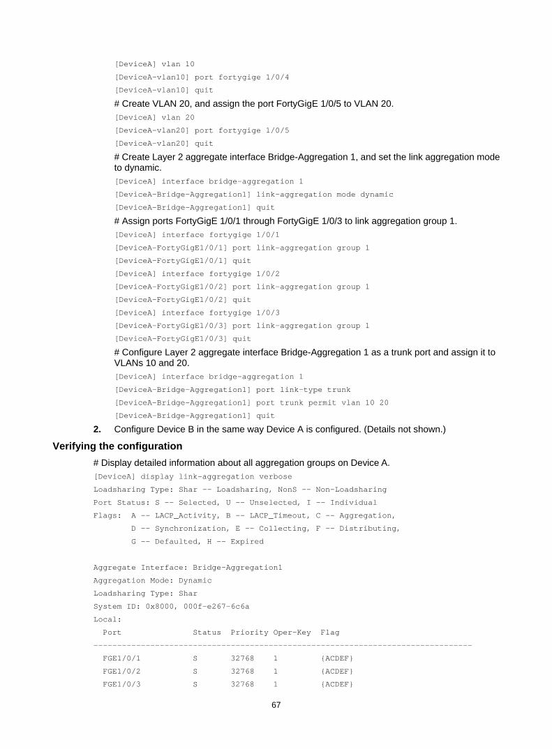
67
[DeviceA] vlan 10
[DeviceA-vlan10] port fortygige 1/0/4
[DeviceA-vlan10] quit
# Create VLAN 20, and assign the port FortyGigE 1/0/5 to VLAN 20. [DeviceA] vlan 20
[DeviceA-vlan20] port fortygige 1/0/5
[DeviceA-vlan20] quit
# Create Layer 2 aggregate interface Bridge-Aggregation 1, and set the link aggregation mode to dynamic. [DeviceA] interface bridge-aggregation 1
[DeviceA-Bridge-Aggregation1] link-aggregation mode dynamic
[DeviceA-Bridge-Aggregation1] quit
# Assign ports FortyGigE 1/0/1 through FortyGigE 1/0/3 to link aggregation group 1. [DeviceA] interface fortygige 1/0/1
[DeviceA-FortyGigE1/0/1] port link-aggregation group 1
[DeviceA-FortyGigE1/0/1] quit
[DeviceA] interface fortygige 1/0/2
[DeviceA-FortyGigE1/0/2] port link-aggregation group 1
[DeviceA-FortyGigE1/0/2] quit
[DeviceA] interface fortygige 1/0/3
[DeviceA-FortyGigE1/0/3] port link-aggregation group 1
[DeviceA-FortyGigE1/0/3] quit
# Configure Layer 2 aggregate interface Bridge-Aggregation 1 as a trunk port and assign it to VLANs 10 and 20. [DeviceA] interface bridge-aggregation 1
[DeviceA-Bridge-Aggregation1] port link-type trunk
[DeviceA-Bridge-Aggregation1] port trunk permit vlan 10 20
[DeviceA-Bridge-Aggregation1] quit
2. Configure Device B in the same way Device A is configured. (Details not shown.)
Verifying the configuration # Display detailed information about all aggregation groups on Device A. [DeviceA] display link-aggregation verbose
Loadsharing Type: Shar -- Loadsharing, NonS -- Non-Loadsharing
Port Status: S -- Selected, U -- Unselected, I -- Individual
Flags: A -- LACP_Activity, B -- LACP_Timeout, C -- Aggregation,
D -- Synchronization, E -- Collecting, F -- Distributing,
G -- Defaulted, H -- Expired
Aggregate Interface: Bridge-Aggregation1
Aggregation Mode: Dynamic
Loadsharing Type: Shar
System ID: 0x8000, 000f-e267-6c6a
Local:
Port Status Priority Oper-Key Flag
--------------------------------------------------------------------------------
FGE1/0/1 S 32768 1 {ACDEF}
FGE1/0/2 S 32768 1 {ACDEF}
FGE1/0/3 S 32768 1 {ACDEF}
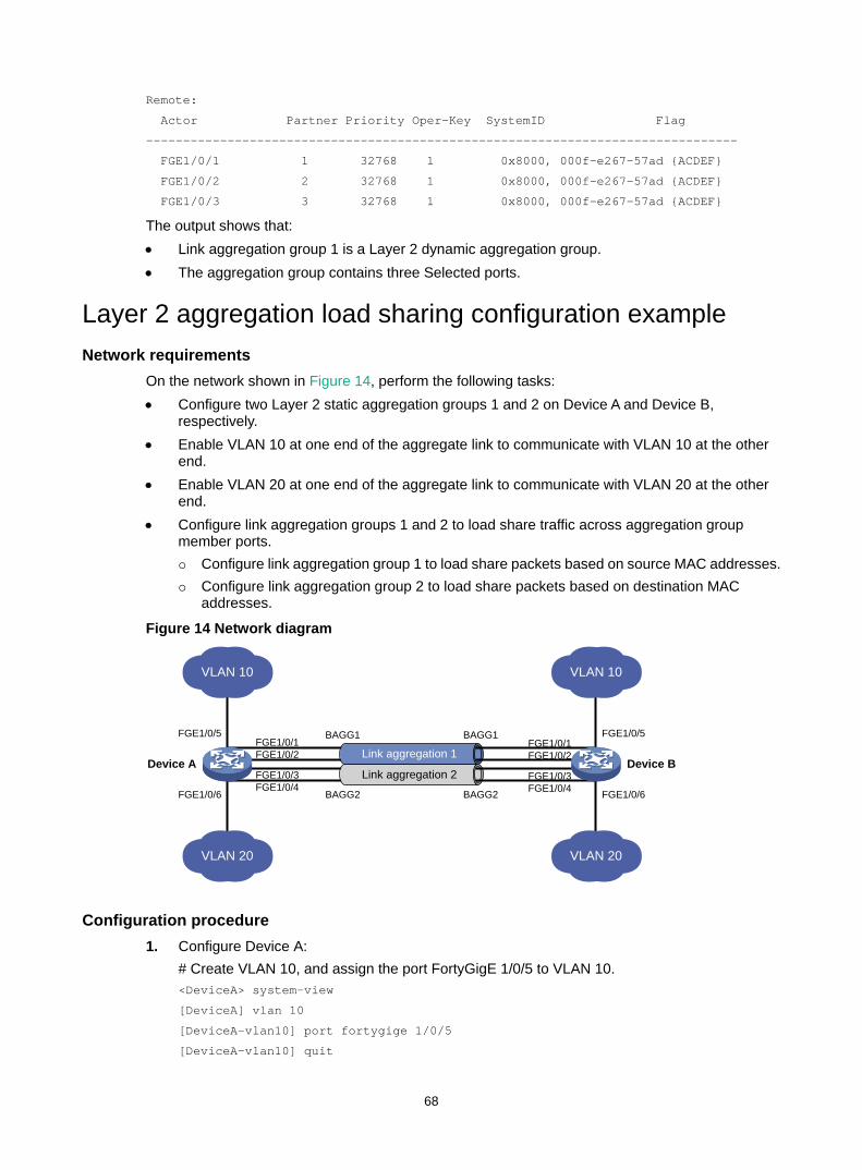
68
Remote:
Actor Partner Priority Oper-Key SystemID Flag
--------------------------------------------------------------------------------
FGE1/0/1 1 32768 1 0x8000, 000f-e267-57ad {ACDEF}
FGE1/0/2 2 32768 1 0x8000, 000f-e267-57ad {ACDEF}
FGE1/0/3 3 32768 1 0x8000, 000f-e267-57ad {ACDEF}
The output shows that: • Link aggregation group 1 is a Layer 2 dynamic aggregation group. • The aggregation group contains three Selected ports.
Layer 2 aggregation load sharing configuration example Network requirements
On the network shown in Figure 14, perform the following tasks: • Configure two Layer 2 static aggregation groups 1 and 2 on Device A and Device B,
respectively. • Enable VLAN 10 at one end of the aggregate link to communicate with VLAN 10 at the other
end. • Enable VLAN 20 at one end of the aggregate link to communicate with VLAN 20 at the other
end. • Configure link aggregation groups 1 and 2 to load share traffic across aggregation group
member ports. Configure link aggregation group 1 to load share packets based on source MAC addresses. Configure link aggregation group 2 to load share packets based on destination MAC
addresses.
Figure 14 Network diagram
Configuration procedure 1. Configure Device A:
# Create VLAN 10, and assign the port FortyGigE 1/0/5 to VLAN 10. <DeviceA> system-view
[DeviceA] vlan 10
[DeviceA-vlan10] port fortygige 1/0/5
[DeviceA-vlan10] quit
Link aggregation 1
BAGG1 BAGG1
Device A Device B Link aggregation 2
BAGG2 BAGG2
VLAN 10
VLAN 20
FGE1/0/5
FGE1/0/6
VLAN 10
VLAN 20
FGE1/0/5
FGE1/0/6
FGE1/0/1FGE1/0/2
FGE1/0/3FGE1/0/4
FGE1/0/1FGE1/0/2
FGE1/0/3FGE1/0/4
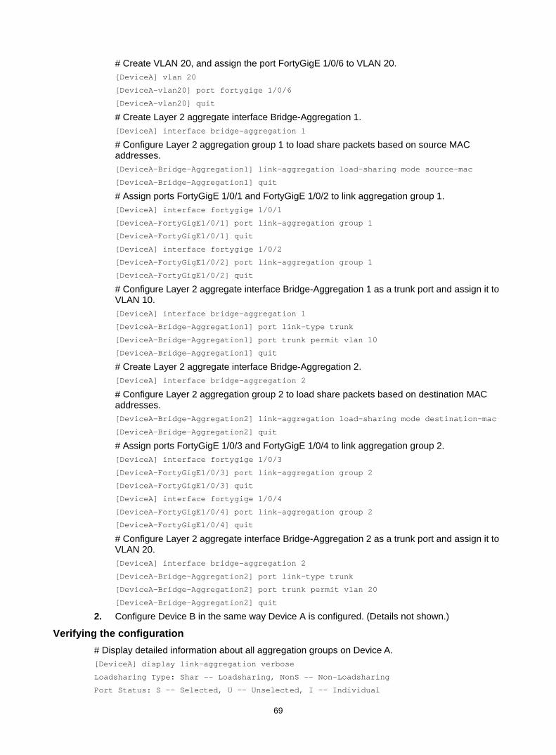
69
# Create VLAN 20, and assign the port FortyGigE 1/0/6 to VLAN 20. [DeviceA] vlan 20
[DeviceA-vlan20] port fortygige 1/0/6
[DeviceA-vlan20] quit
# Create Layer 2 aggregate interface Bridge-Aggregation 1. [DeviceA] interface bridge-aggregation 1
# Configure Layer 2 aggregation group 1 to load share packets based on source MAC addresses. [DeviceA-Bridge-Aggregation1] link-aggregation load-sharing mode source-mac
[DeviceA-Bridge-Aggregation1] quit
# Assign ports FortyGigE 1/0/1 and FortyGigE 1/0/2 to link aggregation group 1. [DeviceA] interface fortygige 1/0/1
[DeviceA-FortyGigE1/0/1] port link-aggregation group 1
[DeviceA-FortyGigE1/0/1] quit
[DeviceA] interface fortygige 1/0/2
[DeviceA-FortyGigE1/0/2] port link-aggregation group 1
[DeviceA-FortyGigE1/0/2] quit
# Configure Layer 2 aggregate interface Bridge-Aggregation 1 as a trunk port and assign it to VLAN 10. [DeviceA] interface bridge-aggregation 1
[DeviceA-Bridge-Aggregation1] port link-type trunk
[DeviceA-Bridge-Aggregation1] port trunk permit vlan 10
[DeviceA-Bridge-Aggregation1] quit
# Create Layer 2 aggregate interface Bridge-Aggregation 2. [DeviceA] interface bridge-aggregation 2
# Configure Layer 2 aggregation group 2 to load share packets based on destination MAC addresses. [DeviceA-Bridge-Aggregation2] link-aggregation load-sharing mode destination-mac
[DeviceA-Bridge-Aggregation2] quit
# Assign ports FortyGigE 1/0/3 and FortyGigE 1/0/4 to link aggregation group 2. [DeviceA] interface fortygige 1/0/3
[DeviceA-FortyGigE1/0/3] port link-aggregation group 2
[DeviceA-FortyGigE1/0/3] quit
[DeviceA] interface fortygige 1/0/4
[DeviceA-FortyGigE1/0/4] port link-aggregation group 2
[DeviceA-FortyGigE1/0/4] quit
# Configure Layer 2 aggregate interface Bridge-Aggregation 2 as a trunk port and assign it to VLAN 20. [DeviceA] interface bridge-aggregation 2
[DeviceA-Bridge-Aggregation2] port link-type trunk
[DeviceA-Bridge-Aggregation2] port trunk permit vlan 20
[DeviceA-Bridge-Aggregation2] quit
2. Configure Device B in the same way Device A is configured. (Details not shown.)
Verifying the configuration # Display detailed information about all aggregation groups on Device A. [DeviceA] display link-aggregation verbose
Loadsharing Type: Shar -- Loadsharing, NonS -- Non-Loadsharing
Port Status: S -- Selected, U -- Unselected, I -- Individual
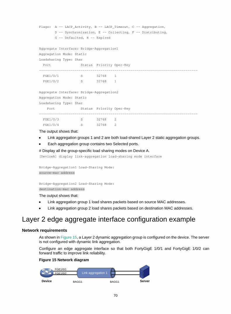
70
Flags: A -- LACP_Activity, B -- LACP_Timeout, C -- Aggregation,
D -- Synchronization, E -- Collecting, F -- Distributing,
G -- Defaulted, H -- Expired
Aggregate Interface: Bridge-Aggregation1
Aggregation Mode: Static
Loadsharing Type: Shar
Port Status Priority Oper-Key
--------------------------------------------------------------------------------
FGE1/0/1 S 32768 1
FGE1/0/2 S 32768 1
Aggregate Interface: Bridge-Aggregation2
Aggregation Mode: Static
Loadsharing Type: Shar
Port Status Priority Oper-Key
--------------------------------------------------------------------------------
FGE1/0/3 S 32768 2
FGE1/0/4 S 32768 2
The output shows that: • Link aggregation groups 1 and 2 are both load-shared Layer 2 static aggregation groups. • Each aggregation group contains two Selected ports.
# Display all the group-specific load sharing modes on Device A. [DeviceA] display link-aggregation load-sharing mode interface
Bridge-Aggregation1 Load-Sharing Mode:
source-mac address
Bridge-Aggregation2 Load-Sharing Mode:
destination-mac address
The output shows that: • Link aggregation group 1 load shares packets based on source MAC addresses. • Link aggregation group 2 load shares packets based on destination MAC addresses.
Layer 2 edge aggregate interface configuration example Network requirements
As shown in Figure 15, a Layer 2 dynamic aggregation group is configured on the device. The server is not configured with dynamic link aggregation.
Configure an edge aggregate interface so that both FortyGigE 1/0/1 and FortyGigE 1/0/2 can forward traffic to improve link reliability.
Figure 15 Network diagram
FGE1/0/1FGE1/0/2 Link aggregation 1
Device ServerBAGG1 BAGG1
71
Configuration procedure # Create Layer 2 aggregate interface Bridge-Aggregation 1, and set the link aggregation mode to dynamic. <Device> system-view
[Device] interface bridge-aggregation 1
[Device-Bridge-Aggregation1] link-aggregation mode dynamic
# Configure Layer 2 aggregate interface Bridge-Aggregation 1 as an edge aggregate interface. [Device-Bridge-Aggregation1] lacp edge-port
[Device-Bridge-Aggregation1] quit
# Assign ports FortyGigE 1/0/1 and FortyGigE 1/0/2 to link aggregation group 1. [Device] interface fortygige 1/0/1
[Device-FortyGigE1/0/1] port link-aggregation group 1
[Device-FortyGigE1/0/1] quit
[Device] interface fortygige 1/0/2
[Device-FortyGigE1/0/2] port link-aggregation group 1
[Device-FortyGigE1/0/2] quit
Verifying the configuration # Display detailed information about all aggregation groups on the device when the server is not configured with dynamic link aggregation. [Device] display link-aggregation verbose
Loadsharing Type: Shar -- Loadsharing, NonS -- Non-Loadsharing
Port Status: S -- Selected, U -- Unselected, I -- Individual
Flags: A -- LACP_Activity, B -- LACP_Timeout, C -- Aggregation,
D -- Synchronization, E -- Collecting, F -- Distributing,
G -- Defaulted, H -- Expired
Aggregate Interface: Bridge-Aggregation1
Aggregation Mode: Dynamic
Loadsharing Type: NonS
System ID: 0x8000, 000f-e267-6c6a
Local:
Port Status Priority Oper-Key Flag
--------------------------------------------------------------------------------
FGE1/0/1 I 32768 1 {AG}
FGE1/0/2 I 32768 1 {AG}
Remote:
Actor Partner Priority Oper-Key SystemID Flag
--------------------------------------------------------------------------------
FGE1/0/1 0 32768 0 0x8000, 0000-0000-0000 {DEF}
FGE1/0/2 0 32768 0 0x8000, 0000-0000-0000 {DEF}
The output shows that FortyGigE 1/0/1 and FortyGigE 1/0/2 are in Individual state when they do not receive LACPDUs from the server. Both FortyGigE 1/0/1 and FortyGigE 1/0/2 can forward traffic. When one port fails, its traffic is automatically switched to the other port.
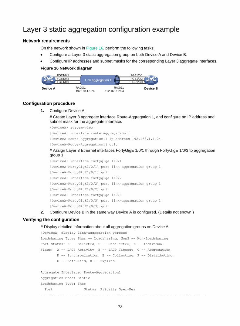
72
Layer 3 static aggregation configuration example Network requirements
On the network shown in Figure 16, perform the following tasks: • Configure a Layer 3 static aggregation group on both Device A and Device B. • Configure IP addresses and subnet masks for the corresponding Layer 3 aggregate interfaces.
Figure 16 Network diagram
Configuration procedure 1. Configure Device A:
# Create Layer 3 aggregate interface Route-Aggregation 1, and configure an IP address and subnet mask for the aggregate interface. <DeviceA> system-view
[DeviceA] interface route-aggregation 1
[DeviceA-Route-Aggregation1] ip address 192.168.1.1 24
[DeviceA-Route-Aggregation1] quit
# Assign Layer 3 Ethernet interfaces FortyGigE 1/0/1 through FortyGigE 1/0/3 to aggregation group 1. [DeviceA] interface fortygige 1/0/1
[DeviceA-FortyGigE1/0/1] port link-aggregation group 1
[DeviceA-FortyGigE1/0/1] quit
[DeviceA] interface fortygige 1/0/2
[DeviceA-FortyGigE1/0/2] port link-aggregation group 1
[DeviceA-FortyGigE1/0/2] quit
[DeviceA] interface fortygige 1/0/3
[DeviceA-FortyGigE1/0/3] port link-aggregation group 1
[DeviceA-FortyGigE1/0/3] quit
2. Configure Device B in the same way Device A is configured. (Details not shown.)
Verifying the configuration # Display detailed information about all aggregation groups on Device A. [DeviceA] display link-aggregation verbose
Loadsharing Type: Shar -- Loadsharing, NonS -- Non-Loadsharing
Port Status: S -- Selected, U -- Unselected, I -- Individual
Flags: A -- LACP_Activity, B -- LACP_Timeout, C -- Aggregation,
D -- Synchronization, E -- Collecting, F -- Distributing,
G -- Defaulted, H -- Expired
Aggregate Interface: Route-Aggregation1
Aggregation Mode: Static
Loadsharing Type: Shar
Port Status Priority Oper-Key
--------------------------------------------------------------------------------
FGE1/0/2FGE1/0/1
FGE1/0/3 Link aggregation 1 FGE1/0/2
FGE1/0/1
FGE1/0/3
Device A Device BRAGG1192.168.1.1/24
RAGG1192.168.1.2/24
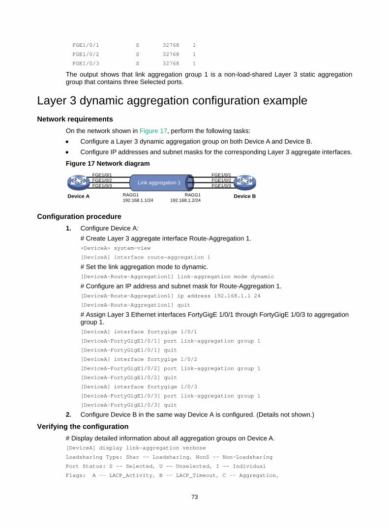
73
FGE1/0/1 S 32768 1
FGE1/0/2 S 32768 1
FGE1/0/3 S 32768 1
The output shows that link aggregation group 1 is a non-load-shared Layer 3 static aggregation group that contains three Selected ports.
Layer 3 dynamic aggregation configuration example Network requirements
On the network shown in Figure 17, perform the following tasks: • Configure a Layer 3 dynamic aggregation group on both Device A and Device B. • Configure IP addresses and subnet masks for the corresponding Layer 3 aggregate interfaces.
Figure 17 Network diagram
Configuration procedure 1. Configure Device A:
# Create Layer 3 aggregate interface Route-Aggregation 1. <DeviceA> system-view
[DeviceA] interface route-aggregation 1
# Set the link aggregation mode to dynamic. [DeviceA-Route-Aggregation1] link-aggregation mode dynamic
# Configure an IP address and subnet mask for Route-Aggregation 1. [DeviceA-Route-Aggregation1] ip address 192.168.1.1 24
[DeviceA-Route-Aggregation1] quit
# Assign Layer 3 Ethernet interfaces FortyGigE 1/0/1 through FortyGigE 1/0/3 to aggregation group 1. [DeviceA] interface fortygige 1/0/1
[DeviceA-FortyGigE1/0/1] port link-aggregation group 1
[DeviceA-FortyGigE1/0/1] quit
[DeviceA] interface fortygige 1/0/2
[DeviceA-FortyGigE1/0/2] port link-aggregation group 1
[DeviceA-FortyGigE1/0/2] quit
[DeviceA] interface fortygige 1/0/3
[DeviceA-FortyGigE1/0/3] port link-aggregation group 1
[DeviceA-FortyGigE1/0/3] quit
2. Configure Device B in the same way Device A is configured. (Details not shown.)
Verifying the configuration # Display detailed information about all aggregation groups on Device A. [DeviceA] display link-aggregation verbose
Loadsharing Type: Shar -- Loadsharing, NonS -- Non-Loadsharing
Port Status: S -- Selected, U -- Unselected, I -- Individual
Flags: A -- LACP_Activity, B -- LACP_Timeout, C -- Aggregation,
FGE1/0/2FGE1/0/1
FGE1/0/3 Link aggregation 1 FGE1/0/2
FGE1/0/1
FGE1/0/3
Device A Device BRAGG1192.168.1.1/24
RAGG1192.168.1.2/24
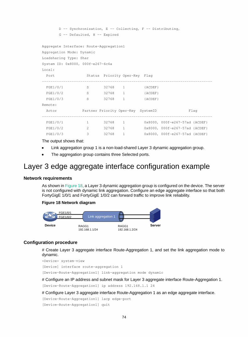
74
D -- Synchronization, E -- Collecting, F -- Distributing,
G -- Defaulted, H -- Expired
Aggregate Interface: Route-Aggregation1
Aggregation Mode: Dynamic
Loadsharing Type: Shar
System ID: 0x8000, 000f-e267-6c6a
Local:
Port Status Priority Oper-Key Flag
--------------------------------------------------------------------------------
FGE1/0/1 S 32768 1 {ACDEF}
FGE1/0/2 S 32768 1 {ACDEF}
FGE1/0/3 S 32768 1 {ACDEF}
Remote:
Actor Partner Priority Oper-Key SystemID Flag
--------------------------------------------------------------------------------
FGE1/0/1 1 32768 1 0x8000, 000f-e267-57ad {ACDEF}
FGE1/0/2 2 32768 1 0x8000, 000f-e267-57ad {ACDEF}
FGE1/0/3 3 32768 1 0x8000, 000f-e267-57ad {ACDEF}
The output shows that: • Link aggregation group 1 is a non-load-shared Layer 3 dynamic aggregation group. • The aggregation group contains three Selected ports.
Layer 3 edge aggregate interface configuration example Network requirements
As shown in Figure 18, a Layer 3 dynamic aggregation group is configured on the device. The server is not configured with dynamic link aggregation. Configure an edge aggregate interface so that both FortyGigE 1/0/1 and FortyGigE 1/0/2 can forward traffic to improve link reliability.
Figure 18 Network diagram
Configuration procedure # Create Layer 3 aggregate interface Route-Aggregation 1, and set the link aggregation mode to dynamic. <Device> system-view
[Device] interface route-aggregation 1
[Device-Route-Aggregation1] link-aggregation mode dynamic
# Configure an IP address and subnet mask for Layer 3 aggregate interface Route-Aggregation 1. [Device-Route-Aggregation1] ip address 192.168.1.1 24
# Configure Layer 3 aggregate interface Route-Aggregation 1 as an edge aggregate interface. [Device-Route-Aggregation1] lacp edge-port
[Device-Route-Aggregation1] quit
FGE1/0/1FGE1/0/2 Link aggregation 1
Device ServerRAGG1192.168.1.1/24
RAGG1192.168.1.2/24
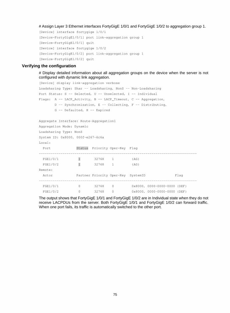
75
# Assign Layer 3 Ethernet interfaces FortyGigE 1/0/1 and FortyGigE 1/0/2 to aggregation group 1. [Device] interface fortygige 1/0/1
[Device-FortyGigE1/0/1] port link-aggregation group 1
[Device-FortyGigE1/0/1] quit
[Device] interface fortygige 1/0/2
[Device-FortyGigE1/0/2] port link-aggregation group 1
[Device-FortyGigE1/0/2] quit
Verifying the configuration # Display detailed information about all aggregation groups on the device when the server is not configured with dynamic link aggregation. [Device] display link-aggregation verbose
Loadsharing Type: Shar -- Loadsharing, NonS -- Non-Loadsharing
Port Status: S -- Selected, U -- Unselected, I -- Individual
Flags: A -- LACP_Activity, B -- LACP_Timeout, C -- Aggregation,
D -- Synchronization, E -- Collecting, F -- Distributing,
G -- Defaulted, H -- Expired
Aggregate Interface: Route-Aggregation1
Aggregation Mode: Dynamic
Loadsharing Type: NonS
System ID: 0x8000, 000f-e267-6c6a
Local:
Port Status Priority Oper-Key Flag
--------------------------------------------------------------------------------
FGE1/0/1 I 32768 1 {AG}
FGE1/0/2 I 32768 1 {AG}
Remote:
Actor Partner Priority Oper-Key SystemID Flag
--------------------------------------------------------------------------------
FGE1/0/1 0 32768 0 0x8000, 0000-0000-0000 {DEF}
FGE1/0/2 0 32768 0 0x8000, 0000-0000-0000 {DEF}
The output shows that FortyGigE 1/0/1 and FortyGigE 1/0/2 are in Individual state when they do not receive LACPDUs from the server. Both FortyGigE 1/0/1 and FortyGigE 1/0/2 can forward traffic. When one port fails, its traffic is automatically switched to the other port.

76
Configuring port isolation The port isolation feature isolates Layer 2 traffic for data privacy and security without using VLANs.
Ports in an isolation group cannot communicate with each other. However, they can communicate with ports outside the isolation group.
Assigning a port to an isolation group The device supports multiple isolation groups, which can be configured manually. The number of ports assigned to an isolation group is not limited.
To assign a port to an isolation group:
Step Command Remarks 1. Enter system view. system-view N/A
2. Create an isolation group.
port-isolate group group-number By default, no isolation group exists.
3. Enter interface view.
• Enter Layer 2 Ethernet interface view: interface interface-type interface-number
• Enter Layer 2 aggregate interface view: interface bridge-aggregation interface-number
• The configuration in Layer 2 Ethernet interface view applies only to the interface.
• The configuration in Layer 2 aggregate interface view applies to the Layer 2 aggregate interface and its aggregation member ports. If the device fails to apply the configuration to the aggregate interface, it does not assign any aggregation member port to the isolation group. If the failure occurs on an aggregation member port, the device skips the port and continues to assign other aggregation member ports to the isolation group.
4. Assign the port to the specified isolation group.
port-isolate enable group group-number
By default, the port is not in any isolation group. You can assign a port to at most one isolation group. If you execute the port-isolate enable group command multiple times, the most recent configuration takes effect.
Displaying and maintaining port isolation Execute display commands in any view.
Task Command Display isolation group information. display port-isolate group [ group-number ]
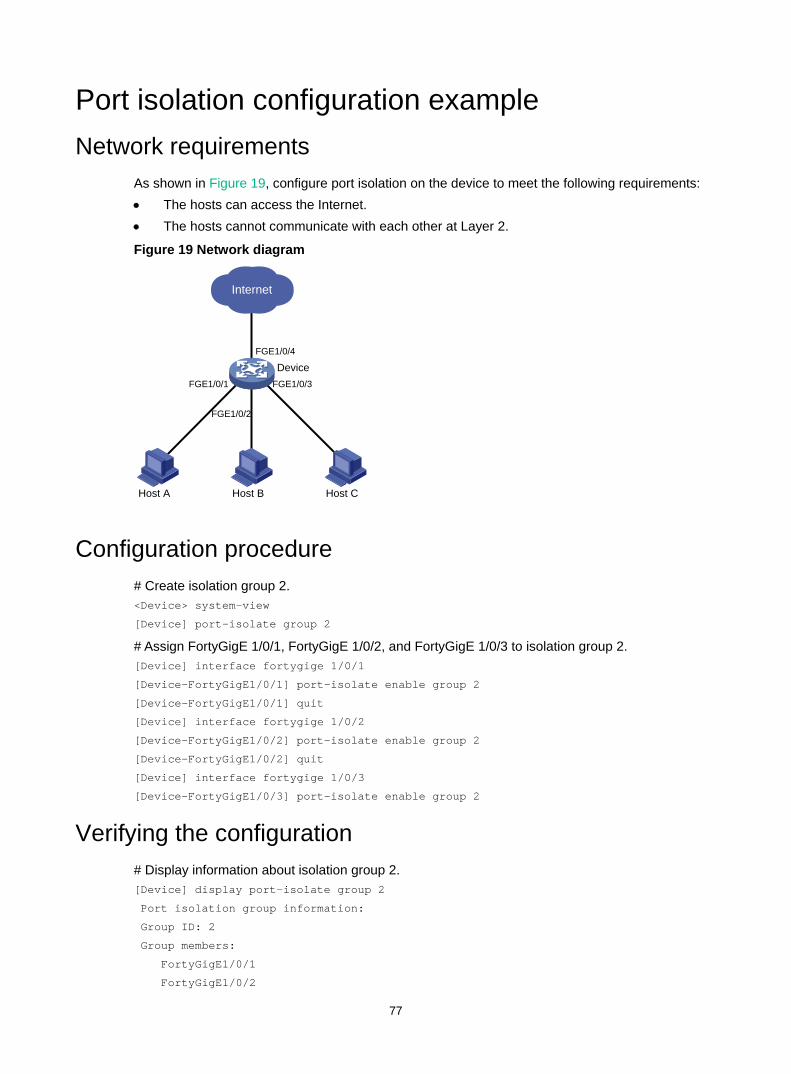
77
Port isolation configuration example Network requirements
As shown in Figure 19, configure port isolation on the device to meet the following requirements: • The hosts can access the Internet. • The hosts cannot communicate with each other at Layer 2.
Figure 19 Network diagram
Configuration procedure # Create isolation group 2. <Device> system-view
[Device] port-isolate group 2
# Assign FortyGigE 1/0/1, FortyGigE 1/0/2, and FortyGigE 1/0/3 to isolation group 2. [Device] interface fortygige 1/0/1
[Device-FortyGigE1/0/1] port-isolate enable group 2
[Device-FortyGigE1/0/1] quit
[Device] interface fortygige 1/0/2
[Device-FortyGigE1/0/2] port-isolate enable group 2
[Device-FortyGigE1/0/2] quit
[Device] interface fortygige 1/0/3
[Device-FortyGigE1/0/3] port-isolate enable group 2
Verifying the configuration # Display information about isolation group 2. [Device] display port-isolate group 2
Port isolation group information:
Group ID: 2
Group members:
FortyGigE1/0/1
FortyGigE1/0/2
Internet
Host A Host B Host C
FGE1/0/2
FGE1/0/1 FGE1/0/3
FGE1/0/4
Device

78
FortyGigE1/0/3
The output shows that interfaces FortyGigE 1/0/1, FortyGigE 1/0/2, and FortyGigE 1/0/3 are assigned to isolation group 2. As a result, Host A, Host B, and Host C are isolated from each other at layer 2.

79
Configuring spanning tree protocols Spanning tree protocols eliminate loops in a physical link-redundant network by selectively blocking redundant links and putting them in a standby state.
The recent versions of STP include the Rapid Spanning Tree Protocol (RSTP), the Per-VLAN Spanning Tree (PVST), and the Multiple Spanning Tree Protocol (MSTP).
STP STP was developed based on the 802.1d standard of IEEE to eliminate loops at the data link layer in a LAN. Networks often have redundant links as backups in case of failures, but loops are a very serious problem. Devices running STP detect loops in the network by exchanging information with one another. They eliminate loops by selectively blocking certain ports to prune the loop structure into a loop-free tree structure. This avoids proliferation and infinite cycling of packets that would occur in a loop network.
In a narrow sense, STP refers to IEEE 802.1d STP. In a broad sense, STP refers to the IEEE 802.1d STP and various enhanced spanning tree protocols derived from that protocol.
STP protocol packets STP uses bridge protocol data units (BPDUs), also known as configuration messages, as its protocol packets. This chapter uses BPDUs to represent all types of spanning tree protocol packets.
STP-enabled network devices exchange BPDUs to establish a spanning tree. BPDUs contain sufficient information for the network devices to complete spanning tree calculation.
STP uses the following types of BPDUs: • Configuration BPDUs—Used by the network devices to calculate a spanning tree and
maintain the spanning tree topology. • Topology change notification (TCN) BPDUs—Notify network devices of network topology
changes.
Configuration BPDUs contain sufficient information for the network devices to complete spanning tree calculation. Important fields in a configuration BPDU include the following: • Root bridge ID—Consisting of the priority and MAC address of the root bridge. • Root path cost—Cost of the path to the root bridge denoted by the root identifier from the
transmitting bridge. • Designated bridge ID—Consisting of the priority and MAC address of the designated bridge. • Designated port ID—Consisting of the priority and global port number of the designated port. • Message age—Age of the configuration BPDU while it propagates in the network. • Max age—Maximum age of the configuration BPDU stored on the switch. • Hello time—Configuration BPDU transmission interval. • Forward delay—Delay that STP bridges use to transit port state.
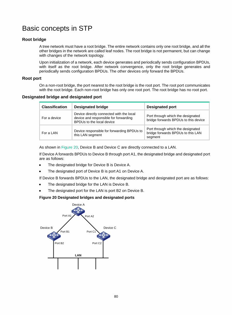
80
Basic concepts in STP Root bridge
A tree network must have a root bridge. The entire network contains only one root bridge, and all the other bridges in the network are called leaf nodes. The root bridge is not permanent, but can change with changes of the network topology.
Upon initialization of a network, each device generates and periodically sends configuration BPDUs, with itself as the root bridge. After network convergence, only the root bridge generates and periodically sends configuration BPDUs. The other devices only forward the BPDUs.
Root port On a non-root bridge, the port nearest to the root bridge is the root port. The root port communicates with the root bridge. Each non-root bridge has only one root port. The root bridge has no root port.
Designated bridge and designated port
Classification Designated bridge Designated port
For a device Device directly connected with the local device and responsible for forwarding BPDUs to the local device
Port through which the designated bridge forwards BPDUs to this device
For a LAN Device responsible for forwarding BPDUs to this LAN segment
Port through which the designated bridge forwards BPDUs to this LAN segment
As shown in Figure 20, Device B and Device C are directly connected to a LAN.
If Device A forwards BPDUs to Device B through port A1, the designated bridge and designated port are as follows: • The designated bridge for Device B is Device A. • The designated port of Device B is port A1 on Device A.
If Device B forwards BPDUs to the LAN, the designated bridge and designated port are as follows: • The designated bridge for the LAN is Device B. • The designated port for the LAN is port B2 on Device B.
Figure 20 Designated bridges and designated ports
Device A
Device B Device C
Port A1 Port A2
Port B1 Port C1
Port B2 Port C2
LAN

81
Path cost Path cost is a reference value used for link selection in STP. To prune the network into a loop-free tree, STP calculates path costs to select the most robust links and block redundant links that are less robust.
Calculation process of the STP algorithm The spanning tree calculation process described in the following sections is an example of a simplified process.
Calculation process The STP algorithm uses the following calculation process: 1. Initialize the network.
Upon initialization of a device, each port generates a BPDU with the following contents: The port as the designated port. The device as the root bridge. 0 as the root path cost. The device ID as the designated bridge ID.
2. Select the root bridge. Initially, each STP-enabled device on the network assumes itself to be the root bridge, with its own device ID as the root bridge ID. By exchanging configuration BPDUs, the devices compare their root bridge IDs to elect the device with the smallest root bridge ID as the root bridge.
3. Root port and designated ports selection on the non-root bridges.
Step Description 1
A non-root–bridge device regards the port on which it received the optimum configuration BPDU as the root port. Table 5 describes how the optimum configuration BPDU is selected.
2
Based on the configuration BPDU and the path cost of the root port, the device calculates a designated port configuration BPDU for each of the other ports. • The root bridge ID is replaced with that of the configuration BPDU of the root port. • The root path cost is replaced with that of the configuration BPDU of the root port plus
the path cost of the root port. • The designated bridge ID is replaced with the ID of this device. • The designated port ID is replaced with the ID of this port.
3
The device compares the calculated configuration BPDU with the configuration BPDU on the port whose port role will be determined, and acts depending on the result of the comparison: • If the calculated configuration BPDU is superior, the device performs the following
tasks: Considers this port as the designated port. Replaces the configuration BPDU on the port with the calculated configuration
BPDU. Periodically sends the calculated configuration BPDU.
• If the configuration BPDU on the port is superior, the device blocks this port without updating its configuration BPDU. The blocked port can receive BPDUs, but cannot send BPDUs or forward data traffic.
When the network topology is stable, only the root port and designated ports forward user traffic. Other ports are all in the blocked state to receive BPDUs but not to forward BPDUs or user traffic.
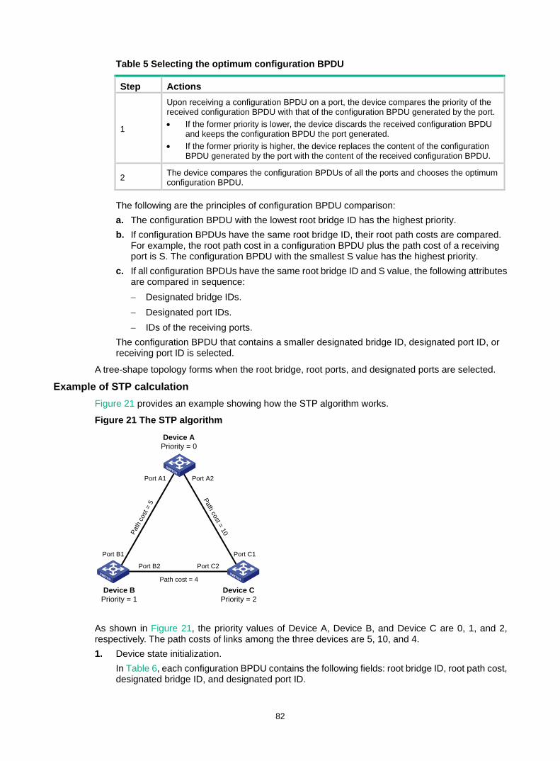
82
Table 5 Selecting the optimum configuration BPDU
Step Actions
1
Upon receiving a configuration BPDU on a port, the device compares the priority of the received configuration BPDU with that of the configuration BPDU generated by the port. • If the former priority is lower, the device discards the received configuration BPDU
and keeps the configuration BPDU the port generated. • If the former priority is higher, the device replaces the content of the configuration
BPDU generated by the port with the content of the received configuration BPDU.
2 The device compares the configuration BPDUs of all the ports and chooses the optimum configuration BPDU.
The following are the principles of configuration BPDU comparison: a. The configuration BPDU with the lowest root bridge ID has the highest priority. b. If configuration BPDUs have the same root bridge ID, their root path costs are compared.
For example, the root path cost in a configuration BPDU plus the path cost of a receiving port is S. The configuration BPDU with the smallest S value has the highest priority.
c. If all configuration BPDUs have the same root bridge ID and S value, the following attributes are compared in sequence: − Designated bridge IDs. − Designated port IDs. − IDs of the receiving ports.
The configuration BPDU that contains a smaller designated bridge ID, designated port ID, or receiving port ID is selected.
A tree-shape topology forms when the root bridge, root ports, and designated ports are selected.
Example of STP calculation Figure 21 provides an example showing how the STP algorithm works.
Figure 21 The STP algorithm
As shown in Figure 21, the priority values of Device A, Device B, and Device C are 0, 1, and 2, respectively. The path costs of links among the three devices are 5, 10, and 4. 1. Device state initialization.
In Table 6, each configuration BPDU contains the following fields: root bridge ID, root path cost, designated bridge ID, and designated port ID.
Device APriority = 0
Device BPriority = 1
Device CPriority = 2
Port A1 Port A2
Port B1
Port B2
Port C1
Port C2
Path
cos
t = 5
Path cost = 10
Path cost = 4
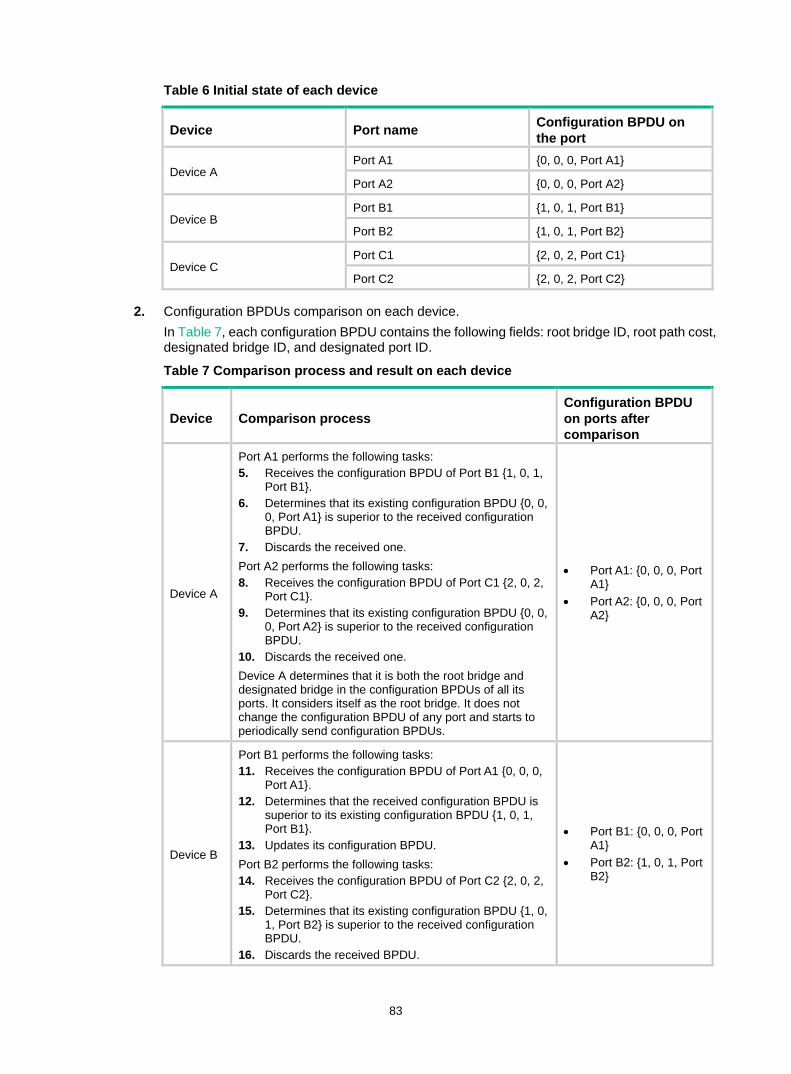
83
Table 6 Initial state of each device
Device Port name Configuration BPDU on the port
Device A Port A1 {0, 0, 0, Port A1}
Port A2 {0, 0, 0, Port A2}
Device B Port B1 {1, 0, 1, Port B1}
Port B2 {1, 0, 1, Port B2}
Device C Port C1 {2, 0, 2, Port C1}
Port C2 {2, 0, 2, Port C2}
2. Configuration BPDUs comparison on each device. In Table 7, each configuration BPDU contains the following fields: root bridge ID, root path cost, designated bridge ID, and designated port ID.
Table 7 Comparison process and result on each device
Device Comparison process Configuration BPDU on ports after comparison
Device A
Port A1 performs the following tasks: 5. Receives the configuration BPDU of Port B1 {1, 0, 1,
Port B1}. 6. Determines that its existing configuration BPDU {0, 0,
0, Port A1} is superior to the received configuration BPDU.
7. Discards the received one. Port A2 performs the following tasks: 8. Receives the configuration BPDU of Port C1 {2, 0, 2,
Port C1}. 9. Determines that its existing configuration BPDU {0, 0,
0, Port A2} is superior to the received configuration BPDU.
10. Discards the received one. Device A determines that it is both the root bridge and designated bridge in the configuration BPDUs of all its ports. It considers itself as the root bridge. It does not change the configuration BPDU of any port and starts to periodically send configuration BPDUs.
• Port A1: {0, 0, 0, Port A1}
• Port A2: {0, 0, 0, Port A2}
Device B
Port B1 performs the following tasks: 11. Receives the configuration BPDU of Port A1 {0, 0, 0,
Port A1}. 12. Determines that the received configuration BPDU is
superior to its existing configuration BPDU {1, 0, 1, Port B1}.
13. Updates its configuration BPDU. Port B2 performs the following tasks: 14. Receives the configuration BPDU of Port C2 {2, 0, 2,
Port C2}. 15. Determines that its existing configuration BPDU {1, 0,
1, Port B2} is superior to the received configuration BPDU.
16. Discards the received BPDU.
• Port B1: {0, 0, 0, Port A1}
• Port B2: {1, 0, 1, Port B2}

84
Device Comparison process Configuration BPDU on ports after comparison
Device B performs the following tasks: 17. Compares the configuration BPDUs of all its ports. 18. Decides that the configuration BPDU of Port B1 is the
optimum. 19. Selects Port B1 as the root port with the configuration
BPDU unchanged. Based on the configuration BPDU and path cost of the root port, Device B calculates a designated port configuration BPDU for Port B2 {0, 5, 1, Port B2}. Device B compares it with the existing configuration BPDU of Port B2 {1, 0, 1, Port B2}. Device B determines that the calculated one is superior, and determines that Port B2 is the designated port. It replaces the configuration BPDU on Port B2 with the calculated one, and periodically sends the calculated configuration BPDU.
• Root port (Port B1): {0, 0, 0, Port A1}
• Designated port (Port B2): {0, 5, 1, Port B2}
Device C
Port C1 performs the following tasks: 20. Receives the configuration BPDU of Port A2 {0, 0, 0,
Port A2}. 21. Determines that the received configuration BPDU is
superior to its existing configuration BPDU {2, 0, 2, Port C1}.
22. Updates its configuration BPDU. Port C2 performs the following tasks: 23. Receives the original configuration BPDU of Port B2
{1, 0, 1, Port B2}. 24. Determines that the received configuration BPDU is
superior to the existing configuration BPDU {2, 0, 2, Port C2}.
25. Updates its configuration BPDU.
• Port C1: {0, 0, 0, Port A2}
• Port C2: {1, 0, 1, Port B2}
Device C performs the following tasks: 26. Compares the configuration BPDUs of all its ports. 27. Decides that the configuration BPDU of Port C1 is the
optimum. 28. Selects Port C1 as the root port with the configuration
BPDU unchanged. Based on the configuration BPDU and path cost of the root port, Device C calculates the configuration BPDU of Port C2 {0, 10, 2, Port C2}. Device C compares it with the existing configuration BPDU of Port C2 {1, 0, 1, Port B2}. Device C determines that the calculated configuration BPDU is superior to the existing one, selects Port C2 as the designated port, and replaces the configuration BPDU of Port C2 with the calculated one.
• Root port (Port C1): {0, 0, 0, Port A2}
• Designated port (Port C2): {0, 10, 2, Port C2}
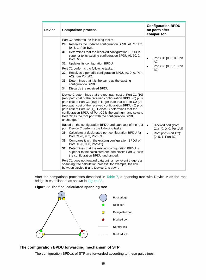
85
Device Comparison process Configuration BPDU on ports after comparison
Port C2 performs the following tasks: 29. Receives the updated configuration BPDU of Port B2
{0, 5, 1, Port B2}. 30. Determines that the received configuration BPDU is
superior to its existing configuration BPDU {0, 10, 2, Port C2}.
31. Updates its configuration BPDU. Port C1 performs the following tasks: 32. Receives a periodic configuration BPDU {0, 0, 0, Port
A2} from Port A2. 33. Determines that it is the same as the existing
configuration BPDU. 34. Discards the received BPDU.
• Port C1: {0, 0, 0, Port A2}
• Port C2: {0, 5, 1, Port B2}
Device C determines that the root path cost of Port C1 (10) (root path cost of the received configuration BPDU (0) plus path cost of Port C1 (10)) is larger than that of Port C2 (9) (root path cost of the received configuration BPDU (5) plus path cost of Port C2 (4)). Device C determines that the configuration BPDU of Port C2 is the optimum, and selects Port C2 as the root port with the configuration BPDU unchanged. Based on the configuration BPDU and path cost of the root port, Device C performs the following tasks: 35. Calculates a designated port configuration BPDU for
Port C1 {0, 9, 2, Port C1}. 36. Compares it with the existing configuration BPDU of
Port C1 {0, 0, 0, Port A2}. 37. Determines that the existing configuration BPDU is
superior to the calculated one and blocks Port C1 with the configuration BPDU unchanged.
Port C1 does not forward data until a new event triggers a spanning tree calculation process: for example, the link between Device B and Device C is down.
• Blocked port (Port C1): {0, 0, 0, Port A2}
• Root port (Port C2): {0, 5, 1, Port B2}
After the comparison processes described in Table 7, a spanning tree with Device A as the root bridge is established, as shown in Figure 22.
Figure 22 The final calculated spanning tree
The configuration BPDU forwarding mechanism of STP The configuration BPDUs of STP are forwarded according to these guidelines:
A
B C
Root port
Designated port
Root bridge
Normal link
Blocked link
Blocked port

86
• Upon network initiation, every device regards itself as the root bridge and generates configuration BPDUs with itself as the root. Then it sends the configuration BPDUs at a regular hello interval.
• If the root port received a configuration BPDU superior to the configuration BPDU of the port, the device performs the following tasks: Increases the message age carried in the configuration BPDU. Starts a timer to time the configuration BPDU. Sends this configuration BPDU through the designated port.
• If a designated port receives a configuration BPDU with a lower priority than its configuration BPDU, the port immediately responds with its configuration BPDU.
• If a path fails, the root port on this path no longer receives new configuration BPDUs and the old configuration BPDUs will be discarded due to timeout. The device generates a configuration BPDU with itself as the root and sends the BPDUs and TCN BPDUs. This triggers a new spanning tree calculation process to establish a new path to restore the network connectivity.
However, the newly calculated configuration BPDU cannot be propagated throughout the network immediately. As a result, the old root ports and designated ports that have not detected the topology change continue forwarding data along the old path. If the new root ports and designated ports begin to forward data as soon as they are elected, a temporary loop might occur.
STP timers The most important timing parameters in STP calculation are forward delay, hello time, and max age. • Forward delay
Forward delay is the delay time for port state transition. A path failure can cause spanning tree recalculation to adapt the spanning tree structure to the change. However, the resulting new configuration BPDU cannot propagate throughout the network immediately. If the newly elected root ports and designated ports start to forward data immediately, a temporary loop will likely occur. The newly elected root ports or designated ports require twice the forward delay time before they transit to the forwarding state. This allows the new configuration BPDU to propagate throughout the network.
• Hello time The device sends hello packets at the hello time interval to the neighboring devices to make sure the paths are fault-free.
• Max age The device uses the max age to determine whether a stored configuration BPDU has expired and discards it if the max age is exceeded.
RSTP RSTP achieves rapid network convergence by allowing a newly elected root port or designated port to enter the forwarding state much faster than STP.
A newly elected RSTP root port rapidly enters the forwarding state when the following conditions exist: • The old root port on the device has stopped forwarding data. • The upstream designated port has started forwarding data.
A newly elected RSTP designated port rapidly enters the forwarding state if it is an edge port or it connects to a point-to-point link. • A port that directly connects to a user terminal can be configured as an edge port. Edge ports
directly enter the forwarding state.
87
• When a designated port connects to a point-to-point link, it enters the forwarding state immediately after the device receives a handshake response from the directly connected device.
PVST In an STP- or RSTP-enabled LAN, all bridges share one spanning tree. Traffic from all VLANs is forwarded along the spanning tree, and ports cannot be blocked on a per-VLAN basis to prune loops.
PVST allows every VLAN to have its own spanning tree, which increases utilization of links and bandwidth. Because each VLAN runs STP or RSTP independently, a spanning tree only serves its VLAN.
A PVST-enabled H3C device can communicate with a third-party device that is running Rapid PVST or PVST. The PVST-enabled H3C device supports fast network convergence like RSTP when connected to PVST-enabled H3C devices or third-party devices enabled with Rapid PVST.
A port's link type determines the type of BPDUs the port sends. • An access port sends STP BPDUs. • A trunk or hybrid port sends STP BPDUs in VLAN 1 and sends PVST BPDUs in other VLANs.
MSTP MSTP overcomes the following STP, RSTP, and PVST limitations: • STP limitations—STP does not support rapid state transition of ports. A newly elected port
must wait twice the forward delay time before it transits to the forwarding state. • RSTP limitations—Although RSTP enables faster network convergence than STP, RSTP fails
to provide load balancing among VLANs. As with STP, all RSTP bridges in a LAN share one spanning tree and forward packets from all VLANs along this spanning tree.
• PVST limitations—Because each VLAN has its spanning tree, the amount of PVST BPDUs is proportional to the number of VLANs on a trunk or hybrid port. When the trunk or hybrid port permits too many VLANs, both resources and calculations for maintaining the VLAN spanning trees increase dramatically. If a status change occurs on the trunk or hybrid port that permits multiple VLANs, the device CPU will be overburdened with recalculating the affected spanning trees. As a result, network performance is degraded.
MSTP features Developed based on IEEE 802.1s, MSTP overcomes the limitations of STP, RSTP, and PVST. In addition to supporting rapid network convergence, it allows data flows of different VLANs to be forwarded along separate paths. This provides a better load sharing mechanism for redundant links.
MSTP provides the following features: • MSTP divides a switched network into multiple regions, each of which contains multiple
spanning trees that are independent of one another. • MSTP supports mapping VLANs to spanning tree instances by means of a VLAN-to-instance
mapping table. MSTP can reduce communication overheads and resource usage by mapping multiple VLANs to one instance.
• MSTP prunes a loop network into a loop-free tree, which avoids proliferation and endless cycling of packets in a loop network. In addition, it supports load balancing of VLAN data by providing multiple redundant paths for data forwarding.
• MSTP is compatible with STP and RSTP, and partially compatible with PVST.
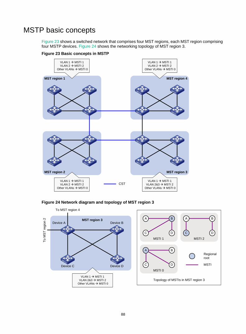
88
MSTP basic concepts Figure 23 shows a switched network that comprises four MST regions, each MST region comprising four MSTP devices. Figure 24 shows the networking topology of MST region 3.
Figure 23 Basic concepts in MSTP
Figure 24 Network diagram and topology of MST region 3
MST region 1
MST region 2 MST region 3
MST region 4
VLAN 1 à MSTI 1VLAN 2 à MSTI 2
Other VLANs à MSTI 0
VLAN 1 à MSTI 1VLAN 2 à MSTI 2
Other VLANs à MSTI 0
VLAN 1 à MSTI 1VLAN 2 à MSTI 2
Other VLANs à MSTI 0
VLAN 1 à MSTI 1VLAN 2&3 à MSTI 2
Other VLANs à MSTI 0CST
MST region 3Device A
Device C
Device B
Device D
VLAN 1 à MSTI 1VLAN 2&3 à MSTI 2
Other VLANs à MSTI 0
To MST region 4
To M
ST re
gion
2 BA
C D
MSTI 1
A B
C D
MSTI 0
B
D
MSTI 2
C
A
Regional root
MSTI
Topology of MSTIs in MST region 3
89
MST region A multiple spanning tree region (MST region) consists of multiple devices in a switched network and the network segments among them. All these devices have the following characteristics: • A spanning tree protocol enabled • Same region name • Same VLAN-to-instance mapping configuration • Same MSTP revision level • Physically linked together
Multiple MST regions can exist in a switched network. You can assign multiple devices to the same MST region as shown in Figure 23. • The switched network comprises four MST regions, MST region 1 through MST region 4. • All devices in each MST region have the same MST region configuration.
MSTI MSTP can generate multiple independent spanning trees in an MST region, and each spanning tree is mapped to the specific VLANs. Each spanning tree is referred to as a multiple spanning tree instance (MSTI).
In Figure 24, MST region 3 comprises three MSTIs, MSTI 1, MSTI 2, and MSTI 0.
VLAN-to-instance mapping table As an attribute of an MST region, the VLAN-to-instance mapping table describes the mapping relationships between VLANs and MSTIs.
In Figure 24, the VLAN-to-instance mapping table of MST region 3 is as follows: • VLAN 1 to MSTI 1. • VLAN 2 and VLAN 3 to MSTI 2. • Other VLANs to MSTI 0.
MSTP achieves load balancing by means of the VLAN-to-instance mapping table.
CST The common spanning tree (CST) is a single spanning tree that connects all MST regions in a switched network. If you regard each MST region as a device, the CST is a spanning tree calculated by these devices through STP or RSTP.
The blue lines in Figure 23 represent the CST.
IST An internal spanning tree (IST) is a spanning tree that runs in an MST region. It is also called MSTI 0, a special MSTI to which all VLANs are mapped by default.
In Figure 23, MSTI 0 is the IST in MST region 3.
CIST The common and internal spanning tree (CIST) is a single spanning tree that connects all devices in a switched network. It consists of the ISTs in all MST regions and the CST.
In Figure 23, the ISTs (MSTI 0) in all MST regions plus the inter-region CST constitute the CIST of the entire network.
Regional root The root bridge of the IST or an MSTI within an MST region is the regional root of the IST or MSTI. Based on the topology, different spanning trees in an MST region might have different regional roots, as shown in MST region 3 in Figure 24:
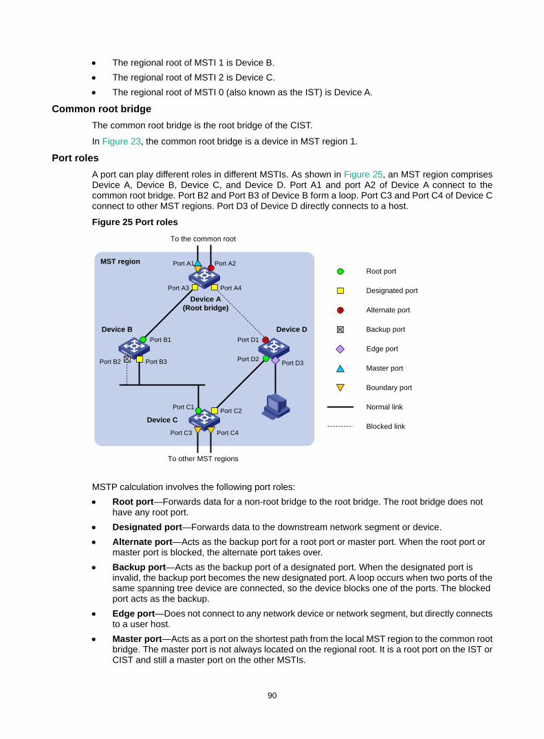
90
• The regional root of MSTI 1 is Device B. • The regional root of MSTI 2 is Device C. • The regional root of MSTI 0 (also known as the IST) is Device A.
Common root bridge The common root bridge is the root bridge of the CIST.
In Figure 23, the common root bridge is a device in MST region 1.
Port roles A port can play different roles in different MSTIs. As shown in Figure 25, an MST region comprises Device A, Device B, Device C, and Device D. Port A1 and port A2 of Device A connect to the common root bridge. Port B2 and Port B3 of Device B form a loop. Port C3 and Port C4 of Device C connect to other MST regions. Port D3 of Device D directly connects to a host.
Figure 25 Port roles
MSTP calculation involves the following port roles: • Root port—Forwards data for a non-root bridge to the root bridge. The root bridge does not
have any root port. • Designated port—Forwards data to the downstream network segment or device. • Alternate port—Acts as the backup port for a root port or master port. When the root port or
master port is blocked, the alternate port takes over. • Backup port—Acts as the backup port of a designated port. When the designated port is
invalid, the backup port becomes the new designated port. A loop occurs when two ports of the same spanning tree device are connected, so the device blocks one of the ports. The blocked port acts as the backup.
• Edge port—Does not connect to any network device or network segment, but directly connects to a user host.
• Master port—Acts as a port on the shortest path from the local MST region to the common root bridge. The master port is not always located on the regional root. It is a root port on the IST or CIST and still a master port on the other MSTIs.
Device A(Root bridge)
Port A1 Port A2Root port
Designated port
Normal link
Blocked link
Alternate port
Backup port
Master port
Boundary port
Device C
Device B Device D
Port A3 Port A4
Port B1
Port B2 Port B3
Port C1 Port C2
Port C3 Port C4
Port D1
Port D2
MST region
To the common root
To other MST regions
Edge port
Port D3
91
• Boundary port—Connects an MST region to another MST region or to an STP/RSTP-running device. In MSTP calculation, a boundary port's role on an MSTI is consistent with its role on the CIST. However, that is not true with master ports. A master port on MSTIs is a root port on the CIST.
Port states In MSTP, a port can be in one of the following states: • Forwarding—The port receives and sends BPDUs, learns MAC addresses, and forwards user
traffic. • Learning—The port receives and sends BPDUs, learns MAC addresses, but does not forward
user traffic. Learning is an intermediate port state. • Discarding—The port receives and sends BPDUs, but does not learn MAC addresses or
forward user traffic.
NOTE: When in different MSTIs, a port can be in different states.
A port state is not exclusively associated with a port role. Table 8 lists the port states that each port role supports. (A check mark [√] indicates that the port supports this state, while a dash [—] indicates that the port does not support this state.)
Table 8 Port states that different port roles support
Port role (right) Port state (below)
Root port/master port
Designated port Alternate port Backup port
Forwarding √ √ — —
Learning √ √ — —
Discarding √ √ √ √
How MSTP works MSTP divides an entire Layer 2 network into multiple MST regions, which are connected by a calculated CST. Inside an MST region, multiple spanning trees, called MSTIs, are calculated. Among these MSTIs, MSTI 0 is the IST.
Like STP, MSTP uses configuration BPDUs to calculate spanning trees. An important difference is that an MSTP BPDU carries the MSTP configuration of the bridge from which the BPDU is sent.
CIST calculation During the CIST calculation, the following process takes place: • The device with the highest priority is elected as the root bridge of the CIST. • MSTP generates an IST within each MST region through calculation. • MSTP regards each MST region as a single device and generates a CST among these MST
regions through calculation.
The CST and ISTs constitute the CIST of the entire network.
MSTI calculation Within an MST region, MSTP generates different MSTIs for different VLANs based on the VLAN-to-instance mappings. For each spanning tree, MSTP performs a separate calculation process similar to spanning tree calculation in STP. For more information, see "Calculation process of the STP algorithm."
92
In MSTP, a VLAN packet is forwarded along the following paths: • Within an MST region, the packet is forwarded along the corresponding MSTI. • Between two MST regions, the packet is forwarded along the CST.
MSTP implementation on devices MSTP is compatible with STP and RSTP. Devices that are running MSTP and that are used for spanning tree calculation can identify STP and RSTP protocol packets.
In addition to basic MSTP features, the following features are provided for ease of management: • Root bridge hold • Root bridge backup • Root guard • BPDU guard • Loop guard • TC-BPDU guard • Port role restriction • TC-BPDU transmission restriction
Protocols and standards MSTP is documented in the following protocols and standards: • IEEE 802.1d, Media Access Control (MAC) Bridges • IEEE 802.1w, Part 3: Media Access Control (MAC) Bridges—Amendment 2: Rapid
Reconfiguration • IEEE 802.1s, Virtual Bridged Local Area Networks—Amendment 3: Multiple Spanning Trees • IEEE 802.1Q-REV/D1.3, Media Access Control (MAC) Bridges and Virtual Bridged Local Area
Networks —Clause 13: Spanning tree Protocols
Spanning tree configuration task lists Before configuring a spanning tree, complete the following tasks: • Determine the spanning tree protocol to be used (STP, RSTP, PVST, or MSTP). • Plan the device roles (the root bridge or leaf node).
When you configure spanning tree protocols, follow these restrictions and guidelines: • If both MVRP and a spanning tree protocol are enabled on a device, MVRP packets are
forwarded along MSTIs. To advertise a specific VLAN within the network through MVRP, make sure this VLAN is mapped to an MSTI when you configure the VLAN-to-instance mapping table. For more information about MVRP, see "Configuring MVRP."
• To connect a spanning tree network to a TRILL network, make sure the following requirements are met: The spanning tree protocol is disabled on TRILL ports. An edge port is used to connect the spanning tree network to the TRILL network. The edge
port can quickly transit to the forwarding state. This prevents network topology changes from influencing the TRILL network.
For more information about TRILL, see TRILL Configuration Guide. • The spanning tree configurations are mutually exclusive with service loopback and Smart Link.
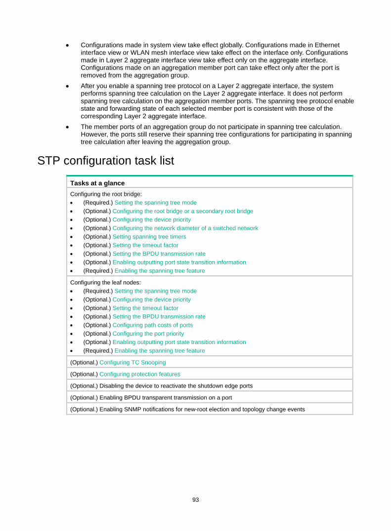
93
• Configurations made in system view take effect globally. Configurations made in Ethernet interface view or WLAN mesh interface view take effect on the interface only. Configurations made in Layer 2 aggregate interface view take effect only on the aggregate interface. Configurations made on an aggregation member port can take effect only after the port is removed from the aggregation group.
• After you enable a spanning tree protocol on a Layer 2 aggregate interface, the system performs spanning tree calculation on the Layer 2 aggregate interface. It does not perform spanning tree calculation on the aggregation member ports. The spanning tree protocol enable state and forwarding state of each selected member port is consistent with those of the corresponding Layer 2 aggregate interface.
• The member ports of an aggregation group do not participate in spanning tree calculation. However, the ports still reserve their spanning tree configurations for participating in spanning tree calculation after leaving the aggregation group.
STP configuration task list
Tasks at a glance Configuring the root bridge: • (Required.) Setting the spanning tree mode • (Optional.) Configuring the root bridge or a secondary root bridge • (Optional.) Configuring the device priority • (Optional.) Configuring the network diameter of a switched network • (Optional.) Setting spanning tree timers • (Optional.) Setting the timeout factor • (Optional.) Setting the BPDU transmission rate • (Optional.) Enabling outputting port state transition information • (Required.) Enabling the spanning tree feature
Configuring the leaf nodes: • (Required.) Setting the spanning tree mode • (Optional.) Configuring the device priority • (Optional.) Setting the timeout factor • (Optional.) Setting the BPDU transmission rate • (Optional.) Configuring path costs of ports • (Optional.) Configuring the port priority • (Optional.) Enabling outputting port state transition information • (Required.) Enabling the spanning tree feature
(Optional.) Configuring TC Snooping
(Optional.) Configuring protection features
(Optional.) Disabling the device to reactivate the shutdown edge ports
(Optional.) Enabling BPDU transparent transmission on a port
(Optional.) Enabling SNMP notifications for new-root election and topology change events

94
RSTP configuration task list
Tasks at a glance Configuring the root bridge: • (Required.) Setting the spanning tree mode • (Optional.) Configuring the root bridge or a secondary root bridge • (Optional.) Configuring the device priority • (Optional.) Configuring the network diameter of a switched network • (Optional.) Setting spanning tree timers • (Optional.) Setting the timeout factor • (Optional.) Setting the BPDU transmission rate • (Optional.) Configuring edge ports • (Optional.) Configuring the port link type • (Optional.) Enabling outputting port state transition information • (Required.) Enabling the spanning tree feature
Configuring the leaf nodes: • (Required.) Setting the spanning tree mode • (Optional.) Configuring the device priority • (Optional.) Setting the timeout factor • (Optional.) Setting the BPDU transmission rate • (Optional.) Configuring edge ports • (Optional.) Configuring path costs of ports • (Optional.) Configuring the port priority • (Optional.) Configuring the port link type • (Optional.) Enabling outputting port state transition information • (Required.) Enabling the spanning tree feature
(Optional.) Performing mCheck
(Optional.) Configuring TC Snooping
(Optional.) Configuring protection features
(Optional.) Disabling the device to reactivate the shutdown edge ports
(Optional.) Enabling BPDU transparent transmission on a port
(Optional.) Enabling SNMP notifications for new-root election and topology change events
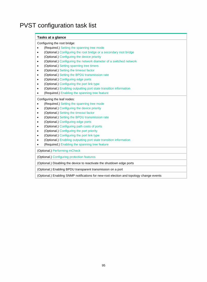
95
PVST configuration task list
Tasks at a glance Configuring the root bridge: • (Required.) Setting the spanning tree mode • (Optional.) Configuring the root bridge or a secondary root bridge • (Optional.) Configuring the device priority • (Optional.) Configuring the network diameter of a switched network • (Optional.) Setting spanning tree timers • (Optional.) Setting the timeout factor • (Optional.) Setting the BPDU transmission rate • (Optional.) Configuring edge ports • (Optional.) Configuring the port link type • (Optional.) Enabling outputting port state transition information • (Required.) Enabling the spanning tree feature
Configuring the leaf nodes: • (Required.) Setting the spanning tree mode • (Optional.) Configuring the device priority • (Optional.) Setting the timeout factor • (Optional.) Setting the BPDU transmission rate • (Optional.) Configuring edge ports • (Optional.) Configuring path costs of ports • (Optional.) Configuring the port priority • (Optional.) Configuring the port link type • (Optional.) Enabling outputting port state transition information • (Required.) Enabling the spanning tree feature
(Optional.) Performing mCheck
(Optional.) Configuring protection features
(Optional.) Disabling the device to reactivate the shutdown edge ports
(Optional.) Enabling BPDU transparent transmission on a port
(Optional.) Enabling SNMP notifications for new-root election and topology change events
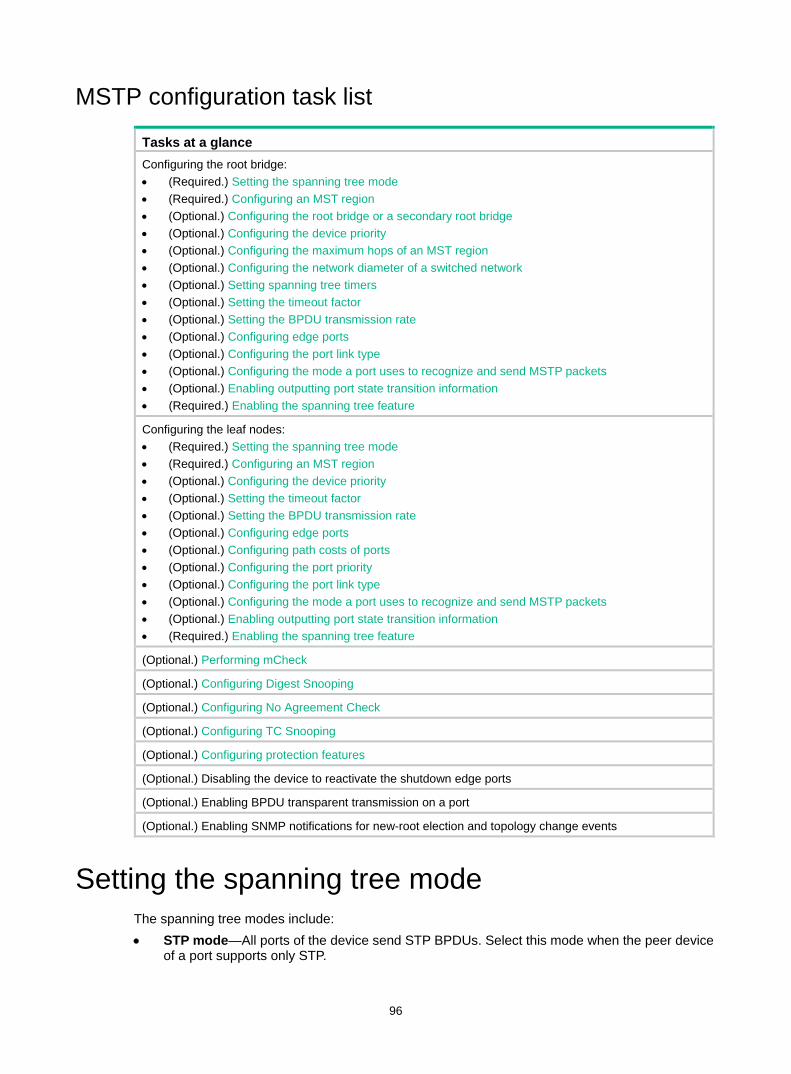
96
MSTP configuration task list
Tasks at a glance Configuring the root bridge: • (Required.) Setting the spanning tree mode • (Required.) Configuring an MST region • (Optional.) Configuring the root bridge or a secondary root bridge • (Optional.) Configuring the device priority • (Optional.) Configuring the maximum hops of an MST region • (Optional.) Configuring the network diameter of a switched network • (Optional.) Setting spanning tree timers • (Optional.) Setting the timeout factor • (Optional.) Setting the BPDU transmission rate • (Optional.) Configuring edge ports • (Optional.) Configuring the port link type • (Optional.) Configuring the mode a port uses to recognize and send MSTP packets • (Optional.) Enabling outputting port state transition information • (Required.) Enabling the spanning tree feature
Configuring the leaf nodes: • (Required.) Setting the spanning tree mode • (Required.) Configuring an MST region • (Optional.) Configuring the device priority • (Optional.) Setting the timeout factor • (Optional.) Setting the BPDU transmission rate • (Optional.) Configuring edge ports • (Optional.) Configuring path costs of ports • (Optional.) Configuring the port priority • (Optional.) Configuring the port link type • (Optional.) Configuring the mode a port uses to recognize and send MSTP packets • (Optional.) Enabling outputting port state transition information • (Required.) Enabling the spanning tree feature
(Optional.) Performing mCheck
(Optional.) Configuring Digest Snooping
(Optional.) Configuring No Agreement Check
(Optional.) Configuring TC Snooping
(Optional.) Configuring protection features
(Optional.) Disabling the device to reactivate the shutdown edge ports
(Optional.) Enabling BPDU transparent transmission on a port
(Optional.) Enabling SNMP notifications for new-root election and topology change events
Setting the spanning tree mode The spanning tree modes include: • STP mode—All ports of the device send STP BPDUs. Select this mode when the peer device
of a port supports only STP.

97
• RSTP mode—All ports of the device send RSTP BPDUs. A port in this mode automatically transits to the STP mode when it receives STP BPDUs from the peer device. A port in this mode does not transit to the MSTP mode when it receives MSTP BPDUs from the peer device.
• MSTP mode—All ports of the device send MSTP BPDUs. A port in this mode automatically transits to the STP mode when receiving STP BPDUs from the peer device. A port in this mode does not transit to the RSTP mode when receiving RSTP BPDUs from the peer device.
• PVST mode—All ports of the device send PVST BPDUs. Each VLAN maintains a spanning tree. In a network, the amount of spanning trees maintained by all devices equals the number of PVST-enabled VLANs multiplied by the number of PVST-enabled ports. If the amount of spanning trees exceeds the capacity of the network, device CPUs will be overloaded. Packet forwarding is interrupted, and the network becomes unstable. The number of PVST-enabled VLANs supported by the device is 144.
The MSTP mode is compatible with the RSTP mode, and the RSTP mode is compatible with the STP mode.
Compatibility of the PVST mode depends on the link type of a port. • On an access port, the PVST mode is compatible with other spanning tree modes in all VLANs. • On a trunk port or hybrid port, the PVST mode is compatible with other spanning tree modes
only in VLAN 1.
To set the spanning tree mode:
Step Command Remarks 1. Enter system view. system-view N/A
2. Set the spanning tree mode. stp mode { mstp |pvst | rstp | stp } The default setting is the MSTP mode.
Configuring an MST region Spanning tree devices belong to the same MST region if they are both connected through a physical link and configured with the following details: • Format selector (0 by default, not configurable). • MST region name. • MST region revision level. • VLAN-to-instance mapping entries in the MST region.
The configuration of MST region-related parameters (especially the VLAN-to-instance mapping table) might cause MSTP to begin a new spanning tree calculation. To reduce the possibility of topology instability, the MST region configuration takes effect only after you activate it by doing one of the following: • Use the active region-configuration command. • Enable a spanning tree protocol by using the stp global enable command if the spanning tree
protocol is disabled.
In STP, RSTP, or PVST mode, MST region configurations do not take effect.
To configure an MST region:
Step Command Remarks 1. Enter system view. system-view N/A
2. Enter MST region view. stp region-configuration N/A
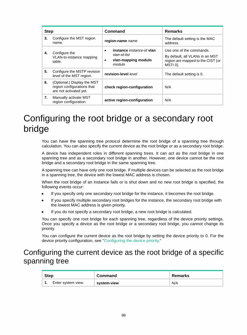
98
Step Command Remarks 3. Configure the MST region
name. region-name name The default setting is the MAC address.
4. Configure the VLAN-to-instance mapping table.
• instance instance-id vlan vlan-id-list
• vlan-mapping modulo modulo
Use one of the commands. By default, all VLANs in an MST region are mapped to the CIST (or MSTI 0).
5. Configure the MSTP revision level of the MST region. revision-level level The default setting is 0.
6. (Optional.) Display the MST region configurations that are not activated yet.
check region-configuration N/A
7. Manually activate MST region configuration. active region-configuration N/A
Configuring the root bridge or a secondary root bridge
You can have the spanning tree protocol determine the root bridge of a spanning tree through calculation. You can also specify the current device as the root bridge or as a secondary root bridge.
A device has independent roles in different spanning trees. It can act as the root bridge in one spanning tree and as a secondary root bridge in another. However, one device cannot be the root bridge and a secondary root bridge in the same spanning tree.
A spanning tree can have only one root bridge. If multiple devices can be selected as the root bridge in a spanning tree, the device with the lowest MAC address is chosen.
When the root bridge of an instance fails or is shut down and no new root bridge is specified, the following events occur: • If you specify only one secondary root bridge for the instance, it becomes the root bridge. • If you specify multiple secondary root bridges for the instance, the secondary root bridge with
the lowest MAC address is given priority. • If you do not specify a secondary root bridge, a new root bridge is calculated.
You can specify one root bridge for each spanning tree, regardless of the device priority settings. Once you specify a device as the root bridge or a secondary root bridge, you cannot change its priority.
You can configure the current device as the root bridge by setting the device priority to 0. For the device priority configuration, see "Configuring the device priority."
Configuring the current device as the root bridge of a specific spanning tree
Step Command Remarks 1. Enter system view. system-view N/A
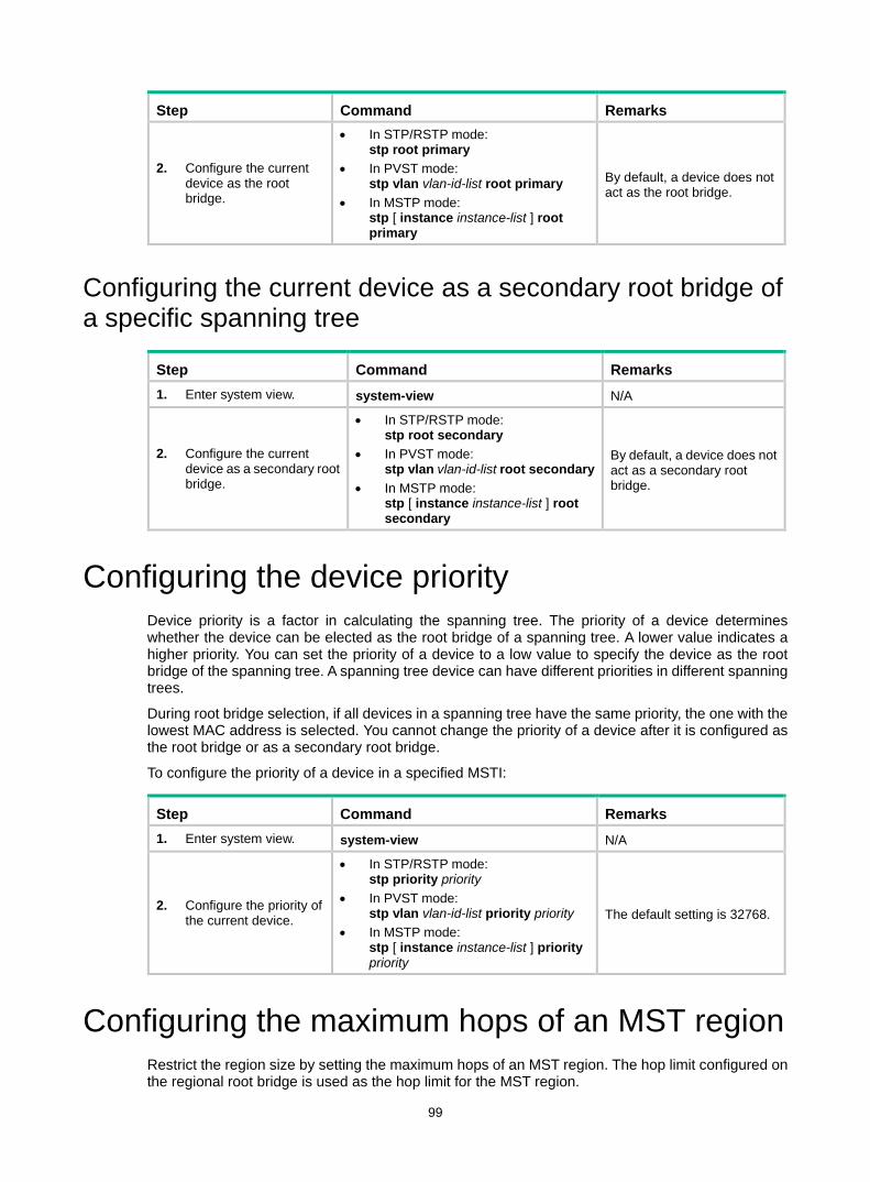
99
Step Command Remarks
2. Configure the current device as the root bridge.
• In STP/RSTP mode: stp root primary
• In PVST mode: stp vlan vlan-id-list root primary
• In MSTP mode: stp [ instance instance-list ] root primary
By default, a device does not act as the root bridge.
Configuring the current device as a secondary root bridge of a specific spanning tree
Step Command Remarks 1. Enter system view. system-view N/A
2. Configure the current device as a secondary root bridge.
• In STP/RSTP mode: stp root secondary
• In PVST mode: stp vlan vlan-id-list root secondary
• In MSTP mode: stp [ instance instance-list ] root secondary
By default, a device does not act as a secondary root bridge.
Configuring the device priority Device priority is a factor in calculating the spanning tree. The priority of a device determines whether the device can be elected as the root bridge of a spanning tree. A lower value indicates a higher priority. You can set the priority of a device to a low value to specify the device as the root bridge of the spanning tree. A spanning tree device can have different priorities in different spanning trees.
During root bridge selection, if all devices in a spanning tree have the same priority, the one with the lowest MAC address is selected. You cannot change the priority of a device after it is configured as the root bridge or as a secondary root bridge.
To configure the priority of a device in a specified MSTI:
Step Command Remarks 1. Enter system view. system-view N/A
2. Configure the priority of the current device.
• In STP/RSTP mode: stp priority priority
• In PVST mode: stp vlan vlan-id-list priority priority
• In MSTP mode: stp [ instance instance-list ] priority priority
The default setting is 32768.
Configuring the maximum hops of an MST region Restrict the region size by setting the maximum hops of an MST region. The hop limit configured on the regional root bridge is used as the hop limit for the MST region.

100
Configuration BPDUs sent by the regional root bridge always have a hop count set to the maximum value. When a device receives this configuration BPDU, it decrements the hop count by one, and uses the new hop count in the BPDUs that it propagates. When the hop count of a BPDU reaches zero, it is discarded by the device that received it. Devices beyond the reach of the maximum hops can no longer participate in spanning tree calculations, so the size of the MST region is limited.
Make this configuration only on the root bridge. All other devices in the MST region use the maximum hop value set for the root bridge.
You can configure the maximum hops of an MST region based on the STP network size. As a best practice, set the maximum hops to a value that is greater than the maximum hops of each edge device to the root bridge.
To configure the maximum number of hops of an MST region:
Step Command Remarks 1. Enter system view. system-view N/A
2. Configure the maximum hops of the MST region. stp max-hops hops The default setting is 20.
Configuring the network diameter of a switched network
Any two terminal devices in a switched network can reach each other through a specific path, and there are a series of devices on the path. The switched network diameter is the maximum number of devices on the path for an edge device to reach another one in the switched network through the root bridge. The network diameter indicates the network size. The bigger the diameter, the larger the network size.
Based on the network diameter you configured, the system automatically sets an optimal hello time, forward delay, and max age for the device.
In STP, RSTP, or MSTP mode, each MST region is considered a device. The configured network diameter takes effect only on the CIST (or the common root bridge) but not on other MSTIs.
In PVST mode, the configured network diameter takes effect only on the root bridges of the specified VLANs.
To configure the network diameter of a switched network:
Step Command Remarks 1. Enter system view. system-view N/A
2. Configure the network diameter of the switched network.
• In STP/RSTP/MSTP mode: stp bridge-diameter diameter
• In PVST mode: stp vlan vlan-id-list bridge-diameter diameter
The default setting is 7.
Setting spanning tree timers The following timers are used for spanning tree calculation: • Forward delay—Delay time for port state transition. To prevent temporary loops on a network,
the spanning tree feature sets an intermediate port state (the learning state) before it transits from the discarding state to the forwarding state. The feature also requires that the port transit
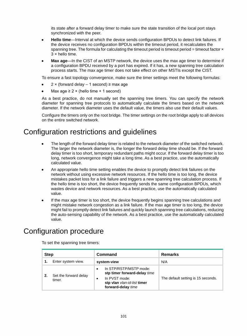
101
its state after a forward delay timer to make sure the state transition of the local port stays synchronized with the peer.
• Hello time—Interval at which the device sends configuration BPDUs to detect link failures. If the device receives no configuration BPDUs within the timeout period, it recalculates the spanning tree. The formula for calculating the timeout period is timeout period = timeout factor × 3 × hello time.
• Max age—In the CIST of an MSTP network, the device uses the max age timer to determine if a configuration BPDU received by a port has expired. If it has, a new spanning tree calculation process starts. The max age timer does not take effect on other MSTIs except the CIST.
To ensure a fast topology convergence, make sure the timer settings meet the following formulas: • 2 × (forward delay – 1 second) ≥ max age • Max age ≥ 2 × (hello time + 1 second)
As a best practice, do not manually set the spanning tree timers. You can specify the network diameter for spanning tree protocols to automatically calculate the timers based on the network diameter. If the network diameter uses the default value, the timers also use their default values.
Configure the timers only on the root bridge. The timer settings on the root bridge apply to all devices on the entire switched network.
Configuration restrictions and guidelines • The length of the forward delay timer is related to the network diameter of the switched network.
The larger the network diameter is, the longer the forward delay time should be. If the forward delay timer is too short, temporary redundant paths might occur. If the forward delay timer is too long, network convergence might take a long time. As a best practice, use the automatically calculated value.
• An appropriate hello time setting enables the device to promptly detect link failures on the network without using excessive network resources. If the hello time is too long, the device mistakes packet loss for a link failure and triggers a new spanning tree calculation process. If the hello time is too short, the device frequently sends the same configuration BPDUs, which wastes device and network resources. As a best practice, use the automatically calculated value.
• If the max age timer is too short, the device frequently begins spanning tree calculations and might mistake network congestion as a link failure. If the max age timer is too long, the device might fail to promptly detect link failures and quickly launch spanning tree calculations, reducing the auto-sensing capability of the network. As a best practice, use the automatically calculated value.
Configuration procedure To set the spanning tree timers:
Step Command Remarks 1. Enter system view. system-view N/A
2. Set the forward delay timer.
• In STP/RSTP/MSTP mode: stp timer forward-delay time
• In PVST mode: stp vlan vlan-id-list timer forward-delay time
The default setting is 15 seconds.
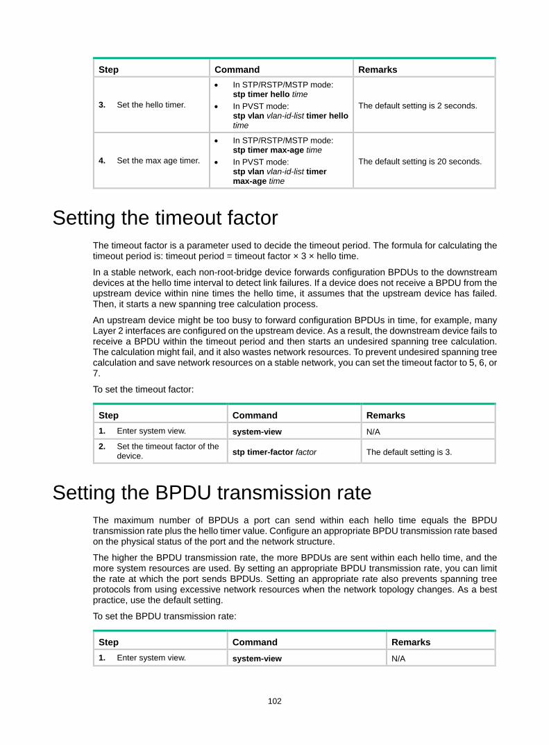
102
Step Command Remarks
3. Set the hello timer.
• In STP/RSTP/MSTP mode: stp timer hello time
• In PVST mode: stp vlan vlan-id-list timer hello time
The default setting is 2 seconds.
4. Set the max age timer.
• In STP/RSTP/MSTP mode: stp timer max-age time
• In PVST mode: stp vlan vlan-id-list timer max-age time
The default setting is 20 seconds.
Setting the timeout factor The timeout factor is a parameter used to decide the timeout period. The formula for calculating the timeout period is: timeout period = timeout factor × 3 × hello time.
In a stable network, each non-root-bridge device forwards configuration BPDUs to the downstream devices at the hello time interval to detect link failures. If a device does not receive a BPDU from the upstream device within nine times the hello time, it assumes that the upstream device has failed. Then, it starts a new spanning tree calculation process.
An upstream device might be too busy to forward configuration BPDUs in time, for example, many Layer 2 interfaces are configured on the upstream device. As a result, the downstream device fails to receive a BPDU within the timeout period and then starts an undesired spanning tree calculation. The calculation might fail, and it also wastes network resources. To prevent undesired spanning tree calculation and save network resources on a stable network, you can set the timeout factor to 5, 6, or 7.
To set the timeout factor:
Step Command Remarks 1. Enter system view. system-view N/A
2. Set the timeout factor of the device. stp timer-factor factor The default setting is 3.
Setting the BPDU transmission rate The maximum number of BPDUs a port can send within each hello time equals the BPDU transmission rate plus the hello timer value. Configure an appropriate BPDU transmission rate based on the physical status of the port and the network structure.
The higher the BPDU transmission rate, the more BPDUs are sent within each hello time, and the more system resources are used. By setting an appropriate BPDU transmission rate, you can limit the rate at which the port sends BPDUs. Setting an appropriate rate also prevents spanning tree protocols from using excessive network resources when the network topology changes. As a best practice, use the default setting.
To set the BPDU transmission rate:
Step Command Remarks 1. Enter system view. system-view N/A
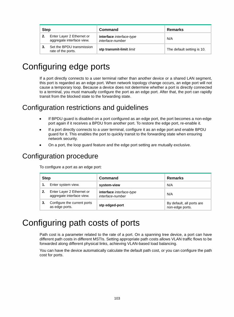
103
Step Command Remarks 2. Enter Layer 2 Ethernet or
aggregate interface view. interface interface-type interface-number N/A
3. Set the BPDU transmission rate of the ports. stp transmit-limit limit The default setting is 10.
Configuring edge ports If a port directly connects to a user terminal rather than another device or a shared LAN segment, this port is regarded as an edge port. When network topology change occurs, an edge port will not cause a temporary loop. Because a device does not determine whether a port is directly connected to a terminal, you must manually configure the port as an edge port. After that, the port can rapidly transit from the blocked state to the forwarding state.
Configuration restrictions and guidelines • If BPDU guard is disabled on a port configured as an edge port, the port becomes a non-edge
port again if it receives a BPDU from another port. To restore the edge port, re-enable it. • If a port directly connects to a user terminal, configure it as an edge port and enable BPDU
guard for it. This enables the port to quickly transit to the forwarding state when ensuring network security.
• On a port, the loop guard feature and the edge port setting are mutually exclusive.
Configuration procedure To configure a port as an edge port:
Step Command Remarks 1. Enter system view. system-view N/A
2. Enter Layer 2 Ethernet or aggregate interface view.
interface interface-type interface-number N/A
3. Configure the current ports as edge ports. stp edged-port By default, all ports are
non-edge ports.
Configuring path costs of ports Path cost is a parameter related to the rate of a port. On a spanning tree device, a port can have different path costs in different MSTIs. Setting appropriate path costs allows VLAN traffic flows to be forwarded along different physical links, achieving VLAN-based load balancing.
You can have the device automatically calculate the default path cost, or you can configure the path cost for ports.
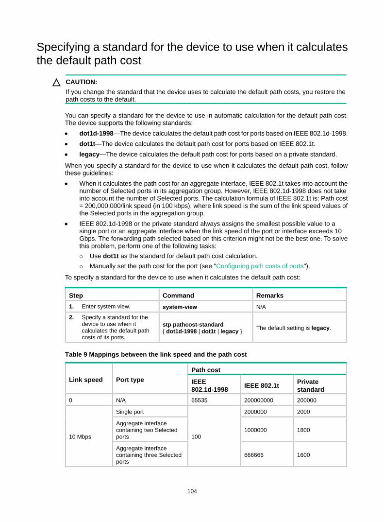
104
Specifying a standard for the device to use when it calculates the default path cost
CAUTION: If you change the standard that the device uses to calculate the default path costs, you restore the path costs to the default.
You can specify a standard for the device to use in automatic calculation for the default path cost. The device supports the following standards: • dot1d-1998—The device calculates the default path cost for ports based on IEEE 802.1d-1998. • dot1t—The device calculates the default path cost for ports based on IEEE 802.1t. • legacy—The device calculates the default path cost for ports based on a private standard.
When you specify a standard for the device to use when it calculates the default path cost, follow these guidelines: • When it calculates the path cost for an aggregate interface, IEEE 802.1t takes into account the
number of Selected ports in its aggregation group. However, IEEE 802.1d-1998 does not take into account the number of Selected ports. The calculation formula of IEEE 802.1t is: Path cost = 200,000,000/link speed (in 100 kbps), where link speed is the sum of the link speed values of the Selected ports in the aggregation group.
• IEEE 802.1d-1998 or the private standard always assigns the smallest possible value to a single port or an aggregate interface when the link speed of the port or interface exceeds 10 Gbps. The forwarding path selected based on this criterion might not be the best one. To solve this problem, perform one of the following tasks: Use dot1t as the standard for default path cost calculation. Manually set the path cost for the port (see "Configuring path costs of ports").
To specify a standard for the device to use when it calculates the default path cost:
Step Command Remarks 1. Enter system view. system-view N/A
2. Specify a standard for the device to use when it calculates the default path costs of its ports.
stp pathcost-standard { dot1d-1998 | dot1t | legacy } The default setting is legacy.
Table 9 Mappings between the link speed and the path cost
Link speed Port type Path cost
IEEE 802.1d-1998 IEEE 802.1t Private
standard 0 N/A 65535 200000000 200000
10 Mbps
Single port
100
2000000 2000
Aggregate interface containing two Selected ports
1000000 1800
Aggregate interface containing three Selected ports
666666 1600
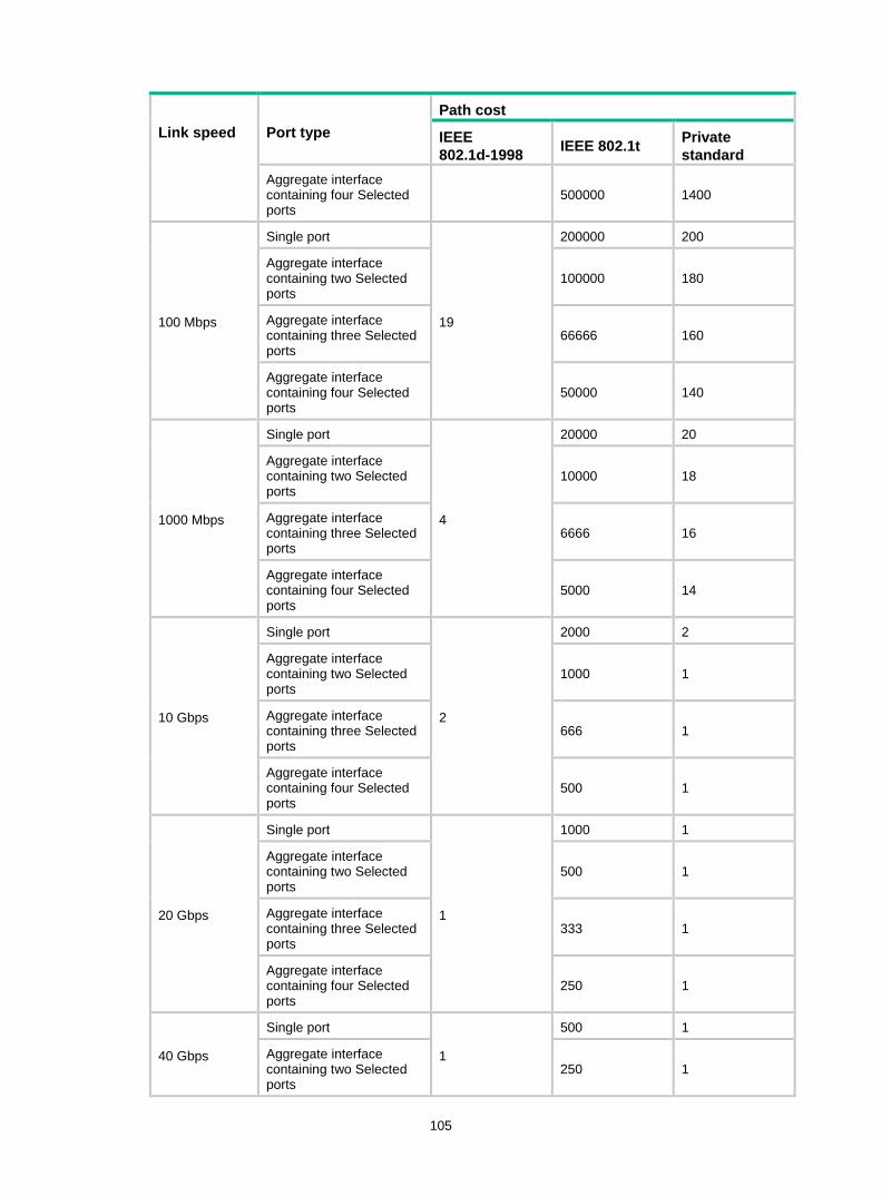
105
Link speed Port type Path cost
IEEE 802.1d-1998 IEEE 802.1t Private
standard Aggregate interface containing four Selected ports
500000 1400
100 Mbps
Single port
19
200000 200
Aggregate interface containing two Selected ports
100000 180
Aggregate interface containing three Selected ports
66666 160
Aggregate interface containing four Selected ports
50000 140
1000 Mbps
Single port
4
20000 20
Aggregate interface containing two Selected ports
10000 18
Aggregate interface containing three Selected ports
6666 16
Aggregate interface containing four Selected ports
5000 14
10 Gbps
Single port
2
2000 2
Aggregate interface containing two Selected ports
1000 1
Aggregate interface containing three Selected ports
666 1
Aggregate interface containing four Selected ports
500 1
20 Gbps
Single port
1
1000 1
Aggregate interface containing two Selected ports
500 1
Aggregate interface containing three Selected ports
333 1
Aggregate interface containing four Selected ports
250 1
40 Gbps
Single port
1
500 1
Aggregate interface containing two Selected ports
250 1

106
Link speed Port type Path cost
IEEE 802.1d-1998 IEEE 802.1t Private
standard Aggregate interface containing three Selected ports
166 1
Aggregate interface containing four Selected ports
125 1
100 Gbps
Single port
1
200 1
Aggregate interface containing two Selected ports
100 1
Aggregate interface containing three Selected ports
66 1
Aggregate interface containing four Selected ports
50 1
Configuring path costs of ports When the path cost of a port changes, the system recalculates the role of the port and initiates a state transition.
To configure the path cost of a port:
Step Command Remarks 1. Enter system view. system-view N/A
2. Enter Layer 2 Ethernet or aggregate interface view.
interface interface-type interface-number N/A
3. Configure the path cost of the ports.
• In STP/RSTP mode: stp cost cost
• In PVST mode: stp vlan vlan-id-list cost cost
• In MSTP mode: stp [ instance instance-list ] cost cost
By default, the system automatically calculates the path cost of each port.
Configuration example # In MSTP mode, perform the following tasks: • Configure the device to calculate the default path costs of its ports by using IEEE 802.1d-1998. • Set the path cost of FortyGigE 1/0/3 to 200 on MSTI 2. <Sysname> system-view
[Sysname] stp pathcost-standard dot1d-1998
Cost of every port will be reset and automatically re-calculated after you change the current pathcost standard. Continue?[Y/N]:y
Cost of every port has been re-calculated.
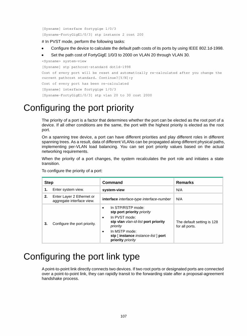
107
[Sysname] interface fortygige 1/0/3
[Sysname-FortyGigE1/0/3] stp instance 2 cost 200
# In PVST mode, perform the following tasks: • Configure the device to calculate the default path costs of its ports by using IEEE 802.1d-1998. • Set the path cost of FortyGigE 1/0/3 to 2000 on VLAN 20 through VLAN 30. <Sysname> system-view
[Sysname] stp pathcost-standard dot1d-1998
Cost of every port will be reset and automatically re-calculated after you change the current pathcost standard. Continue?[Y/N]:y
Cost of every port has been re-calculated
[Sysname] interface fortygige 1/0/3
[Sysname-FortyGigE1/0/3] stp vlan 20 to 30 cost 2000
Configuring the port priority The priority of a port is a factor that determines whether the port can be elected as the root port of a device. If all other conditions are the same, the port with the highest priority is elected as the root port.
On a spanning tree device, a port can have different priorities and play different roles in different spanning trees. As a result, data of different VLANs can be propagated along different physical paths, implementing per-VLAN load balancing. You can set port priority values based on the actual networking requirements.
When the priority of a port changes, the system recalculates the port role and initiates a state transition.
To configure the priority of a port:
Step Command Remarks 1. Enter system view. system-view N/A
2. Enter Layer 2 Ethernet or aggregate interface view. interface interface-type interface-number N/A
3. Configure the port priority.
• In STP/RSTP mode: stp port priority priority
• In PVST mode: stp vlan vlan-id-list port priority priority
• In MSTP mode: stp [ instance instance-list ] port priority priority
The default setting is 128 for all ports.
Configuring the port link type A point-to-point link directly connects two devices. If two root ports or designated ports are connected over a point-to-point link, they can rapidly transit to the forwarding state after a proposal-agreement handshake process.
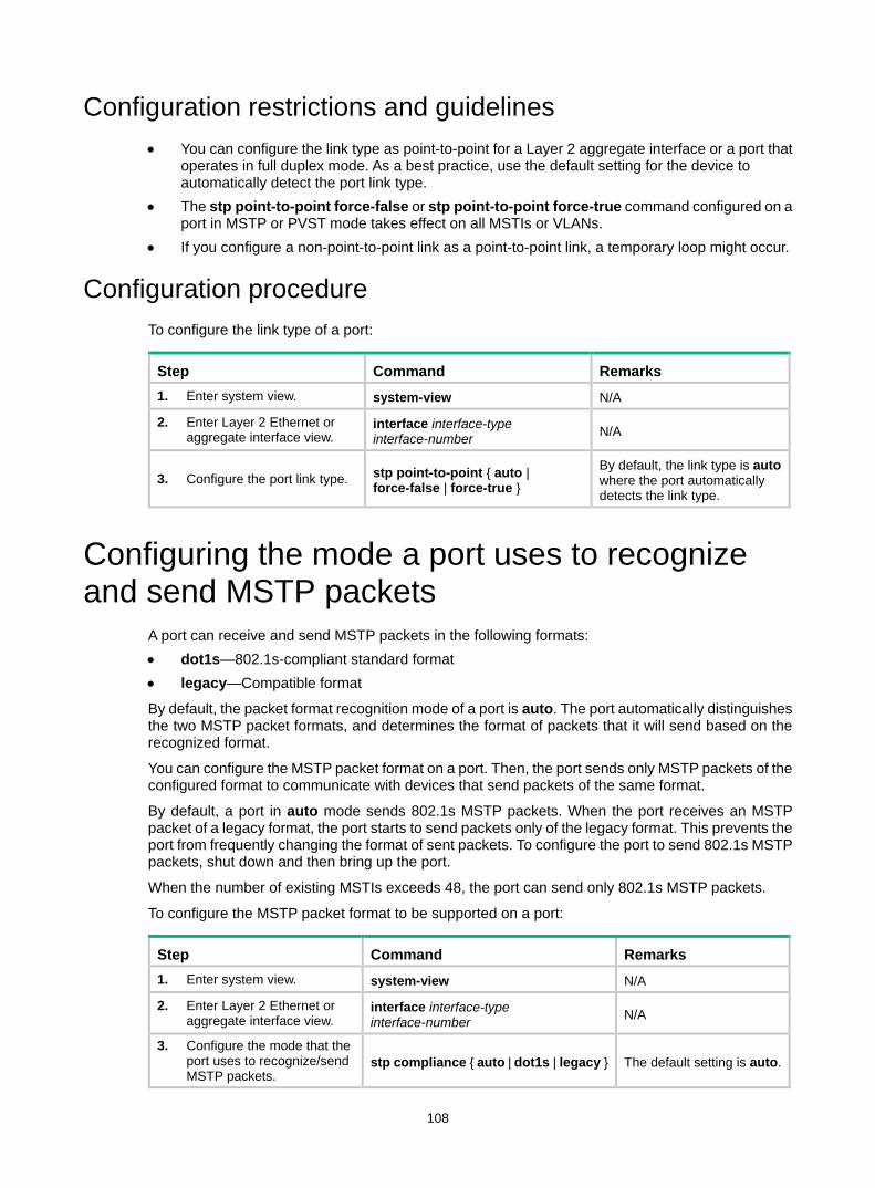
108
Configuration restrictions and guidelines • You can configure the link type as point-to-point for a Layer 2 aggregate interface or a port that
operates in full duplex mode. As a best practice, use the default setting for the device to automatically detect the port link type.
• The stp point-to-point force-false or stp point-to-point force-true command configured on a port in MSTP or PVST mode takes effect on all MSTIs or VLANs.
• If you configure a non-point-to-point link as a point-to-point link, a temporary loop might occur.
Configuration procedure To configure the link type of a port:
Step Command Remarks 1. Enter system view. system-view N/A
2. Enter Layer 2 Ethernet or aggregate interface view.
interface interface-type interface-number N/A
3. Configure the port link type. stp point-to-point { auto | force-false | force-true }
By default, the link type is auto where the port automatically detects the link type.
Configuring the mode a port uses to recognize and send MSTP packets
A port can receive and send MSTP packets in the following formats: • dot1s—802.1s-compliant standard format • legacy—Compatible format
By default, the packet format recognition mode of a port is auto. The port automatically distinguishes the two MSTP packet formats, and determines the format of packets that it will send based on the recognized format.
You can configure the MSTP packet format on a port. Then, the port sends only MSTP packets of the configured format to communicate with devices that send packets of the same format.
By default, a port in auto mode sends 802.1s MSTP packets. When the port receives an MSTP packet of a legacy format, the port starts to send packets only of the legacy format. This prevents the port from frequently changing the format of sent packets. To configure the port to send 802.1s MSTP packets, shut down and then bring up the port.
When the number of existing MSTIs exceeds 48, the port can send only 802.1s MSTP packets.
To configure the MSTP packet format to be supported on a port:
Step Command Remarks 1. Enter system view. system-view N/A
2. Enter Layer 2 Ethernet or aggregate interface view.
interface interface-type interface-number N/A
3. Configure the mode that the port uses to recognize/send MSTP packets.
stp compliance { auto | dot1s | legacy } The default setting is auto.
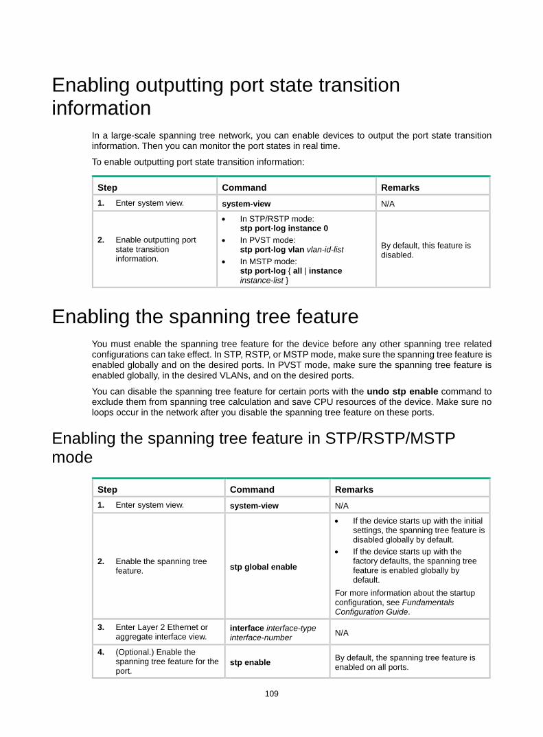
109
Enabling outputting port state transition information
In a large-scale spanning tree network, you can enable devices to output the port state transition information. Then you can monitor the port states in real time.
To enable outputting port state transition information:
Step Command Remarks 1. Enter system view. system-view N/A
2. Enable outputting port state transition information.
• In STP/RSTP mode: stp port-log instance 0
• In PVST mode: stp port-log vlan vlan-id-list
• In MSTP mode: stp port-log { all | instance instance-list }
By default, this feature is disabled.
Enabling the spanning tree feature You must enable the spanning tree feature for the device before any other spanning tree related configurations can take effect. In STP, RSTP, or MSTP mode, make sure the spanning tree feature is enabled globally and on the desired ports. In PVST mode, make sure the spanning tree feature is enabled globally, in the desired VLANs, and on the desired ports.
You can disable the spanning tree feature for certain ports with the undo stp enable command to exclude them from spanning tree calculation and save CPU resources of the device. Make sure no loops occur in the network after you disable the spanning tree feature on these ports.
Enabling the spanning tree feature in STP/RSTP/MSTP mode
Step Command Remarks 1. Enter system view. system-view N/A
2. Enable the spanning tree feature. stp global enable
• If the device starts up with the initial settings, the spanning tree feature is disabled globally by default.
• If the device starts up with the factory defaults, the spanning tree feature is enabled globally by default.
For more information about the startup configuration, see Fundamentals Configuration Guide.
3. Enter Layer 2 Ethernet or aggregate interface view.
interface interface-type interface-number N/A
4. (Optional.) Enable the spanning tree feature for the port.
stp enable By default, the spanning tree feature is enabled on all ports.
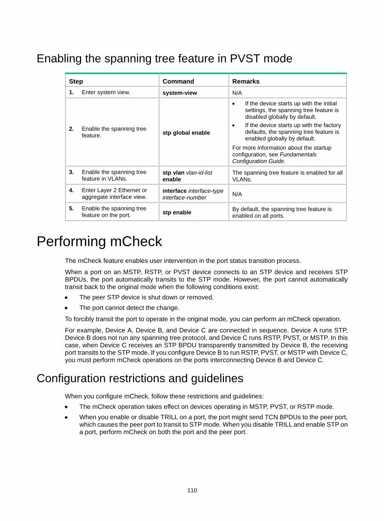
110
Enabling the spanning tree feature in PVST mode
Step Command Remarks 1. Enter system view. system-view N/A
2. Enable the spanning tree feature. stp global enable
• If the device starts up with the initial settings, the spanning tree feature is disabled globally by default.
• If the device starts up with the factory defaults, the spanning tree feature is enabled globally by default.
For more information about the startup configuration, see Fundamentals Configuration Guide.
3. Enable the spanning tree feature in VLANs.
stp vlan vlan-id-list enable
The spanning tree feature is enabled for all VLANs.
4. Enter Layer 2 Ethernet or aggregate interface view.
interface interface-type interface-number N/A
5. Enable the spanning tree feature on the port. stp enable By default, the spanning tree feature is
enabled on all ports.
Performing mCheck The mCheck feature enables user intervention in the port status transition process.
When a port on an MSTP, RSTP, or PVST device connects to an STP device and receives STP BPDUs, the port automatically transits to the STP mode. However, the port cannot automatically transit back to the original mode when the following conditions exist: • The peer STP device is shut down or removed. • The port cannot detect the change.
To forcibly transit the port to operate in the original mode, you can perform an mCheck operation.
For example, Device A, Device B, and Device C are connected in sequence. Device A runs STP, Device B does not run any spanning tree protocol, and Device C runs RSTP, PVST, or MSTP. In this case, when Device C receives an STP BPDU transparently transmitted by Device B, the receiving port transits to the STP mode. If you configure Device B to run RSTP, PVST, or MSTP with Device C, you must perform mCheck operations on the ports interconnecting Device B and Device C.
Configuration restrictions and guidelines When you configure mCheck, follow these restrictions and guidelines: • The mCheck operation takes effect on devices operating in MSTP, PVST, or RSTP mode. • When you enable or disable TRILL on a port, the port might send TCN BPDUs to the peer port,
which causes the peer port to transit to STP mode. When you disable TRILL and enable STP on a port, perform mCheck on both the port and the peer port.
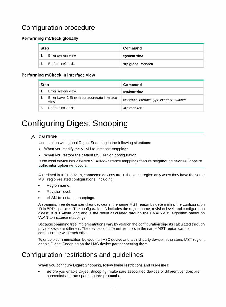
111
Configuration procedure Performing mCheck globally
Step Command
1. Enter system view. system-view
2. Perform mCheck. stp global mcheck
Performing mCheck in interface view
Step Command 1. Enter system view. system-view
2. Enter Layer 2 Ethernet or aggregate interface view. interface interface-type interface-number
3. Perform mCheck. stp mcheck
Configuring Digest Snooping CAUTION:
Use caution with global Digest Snooping in the following situations: • When you modify the VLAN-to-instance mappings. • When you restore the default MST region configuration. If the local device has different VLAN-to-instance mappings than its neighboring devices, loops or traffic interruption will occurs.
As defined in IEEE 802.1s, connected devices are in the same region only when they have the same MST region-related configurations, including: • Region name. • Revision level. • VLAN-to-instance mappings.
A spanning tree device identifies devices in the same MST region by determining the configuration ID in BPDU packets. The configuration ID includes the region name, revision level, and configuration digest. It is 16-byte long and is the result calculated through the HMAC-MD5 algorithm based on VLAN-to-instance mappings.
Because spanning tree implementations vary by vendor, the configuration digests calculated through private keys are different. The devices of different vendors in the same MST region cannot communicate with each other.
To enable communication between an H3C device and a third-party device in the same MST region, enable Digest Snooping on the H3C device port connecting them.
Configuration restrictions and guidelines When you configure Digest Snooping, follow these restrictions and guidelines: • Before you enable Digest Snooping, make sure associated devices of different vendors are
connected and run spanning tree protocols.
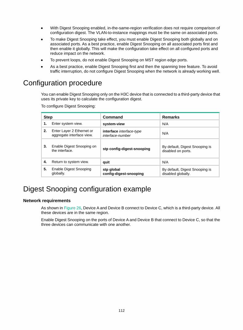
112
• With Digest Snooping enabled, in-the-same-region verification does not require comparison of configuration digest. The VLAN-to-instance mappings must be the same on associated ports.
• To make Digest Snooping take effect, you must enable Digest Snooping both globally and on associated ports. As a best practice, enable Digest Snooping on all associated ports first and then enable it globally. This will make the configuration take effect on all configured ports and reduce impact on the network.
• To prevent loops, do not enable Digest Snooping on MST region edge ports. • As a best practice, enable Digest Snooping first and then the spanning tree feature. To avoid
traffic interruption, do not configure Digest Snooping when the network is already working well.
Configuration procedure You can enable Digest Snooping only on the H3C device that is connected to a third-party device that uses its private key to calculate the configuration digest.
To configure Digest Snooping:
Step Command Remarks 1. Enter system view. system-view N/A
2. Enter Layer 2 Ethernet or aggregate interface view.
interface interface-type interface-number N/A
3. Enable Digest Snooping on the interface. stp config-digest-snooping By default, Digest Snooping is
disabled on ports.
4. Return to system view. quit N/A
5. Enable Digest Snooping globally.
stp global config-digest-snooping
By default, Digest Snooping is disabled globally.
Digest Snooping configuration example Network requirements
As shown in Figure 26, Device A and Device B connect to Device C, which is a third-party device. All these devices are in the same region.
Enable Digest Snooping on the ports of Device A and Device B that connect to Device C, so that the three devices can communicate with one another.
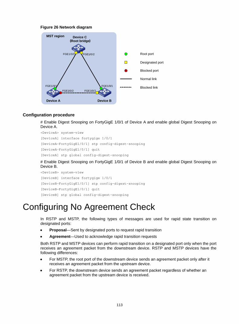
113
Figure 26 Network diagram
Configuration procedure # Enable Digest Snooping on FortyGigE 1/0/1 of Device A and enable global Digest Snooping on Device A. <DeviceA> system-view
[DeviceA] interface fortygige 1/0/1
[DeviceA-FortyGigE1/0/1] stp config-digest-snooping
[DeviceA-FortyGigE1/0/1] quit
[DeviceA] stp global config-digest-snooping
# Enable Digest Snooping on FortyGigE 1/0/1 of Device B and enable global Digest Snooping on Device B. <DeviceB> system-view
[DeviceB] interface fortygige 1/0/1
[DeviceB-FortyGigE1/0/1] stp config-digest-snooping
[DeviceB-FortyGigE1/0/1] quit
[DeviceB] stp global config-digest-snooping
Configuring No Agreement Check In RSTP and MSTP, the following types of messages are used for rapid state transition on designated ports: • Proposal—Sent by designated ports to request rapid transition • Agreement—Used to acknowledge rapid transition requests
Both RSTP and MSTP devices can perform rapid transition on a designated port only when the port receives an agreement packet from the downstream device. RSTP and MSTP devices have the following differences: • For MSTP, the root port of the downstream device sends an agreement packet only after it
receives an agreement packet from the upstream device. • For RSTP, the downstream device sends an agreement packet regardless of whether an
agreement packet from the upstream device is received.
Device C(Root bridge)
FGE1/0/1 FGE1 /0/ 2
FGE1/0/1
FGE1/0/2
FGE1/0/1
FGE1/0/2
Root port
Designated port
Normal link
Blocked link
Blocked port
Device A Device B
MST region
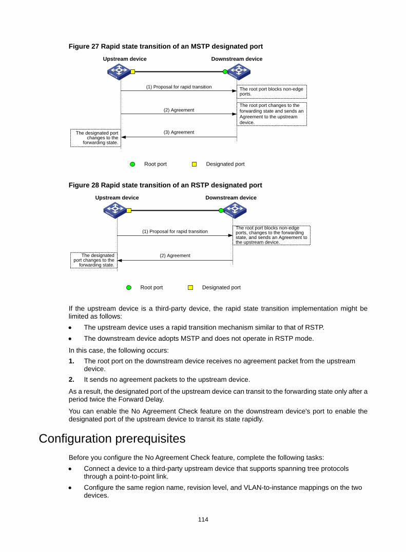
114
Figure 27 Rapid state transition of an MSTP designated port
Figure 28 Rapid state transition of an RSTP designated port
If the upstream device is a third-party device, the rapid state transition implementation might be limited as follows: • The upstream device uses a rapid transition mechanism similar to that of RSTP. • The downstream device adopts MSTP and does not operate in RSTP mode.
In this case, the following occurs: 1. The root port on the downstream device receives no agreement packet from the upstream
device. 2. It sends no agreement packets to the upstream device.
As a result, the designated port of the upstream device can transit to the forwarding state only after a period twice the Forward Delay.
You can enable the No Agreement Check feature on the downstream device's port to enable the designated port of the upstream device to transit its state rapidly.
Configuration prerequisites Before you configure the No Agreement Check feature, complete the following tasks: • Connect a device to a third-party upstream device that supports spanning tree protocols
through a point-to-point link. • Configure the same region name, revision level, and VLAN-to-instance mappings on the two
devices.
Root port Designated port
Upstream device Downstream device
(1) Proposal for rapid transition
(3) Agreement
The root port blocks non-edge ports.
The root port changes to the forwarding state and sends an Agreement to the upstream device.
(2) Agreement
The designated port changes to the
forwarding state.
Root port Designated port
Upstream device Downstream device
(1) Proposal for rapid transition
(2) Agreement
The root port blocks non-edge ports, changes to the forwarding state, and sends an Agreement to the upstream device.
The designated port changes to the
forwarding state.
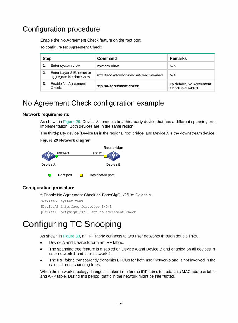
115
Configuration procedure Enable the No Agreement Check feature on the root port.
To configure No Agreement Check:
Step Command Remarks
1. Enter system view. system-view N/A
2. Enter Layer 2 Ethernet or aggregate interface view. interface interface-type interface-number N/A
3. Enable No Agreement Check. stp no-agreement-check By default, No Agreement
Check is disabled.
No Agreement Check configuration example Network requirements
As shown in Figure 29, Device A connects to a third-party device that has a different spanning tree implementation. Both devices are in the same region.
The third-party device (Device B) is the regional root bridge, and Device A is the downstream device.
Figure 29 Network diagram
Configuration procedure # Enable No Agreement Check on FortyGigE 1/0/1 of Device A. <DeviceA> system-view
[DeviceA] interface fortygige 1/0/1
[DeviceA-FortyGigE1/0/1] stp no-agreement-check
Configuring TC Snooping As shown in Figure 30, an IRF fabric connects to two user networks through double links. • Device A and Device B form an IRF fabric. • The spanning tree feature is disabled on Device A and Device B and enabled on all devices in
user network 1 and user network 2. • The IRF fabric transparently transmits BPDUs for both user networks and is not involved in the
calculation of spanning trees.
When the network topology changes, it takes time for the IRF fabric to update its MAC address table and ARP table. During this period, traffic in the network might be interrupted.
FGE1/0/1
Device A Device B
FGE1/0/1
Root port Designated port
Root bridge
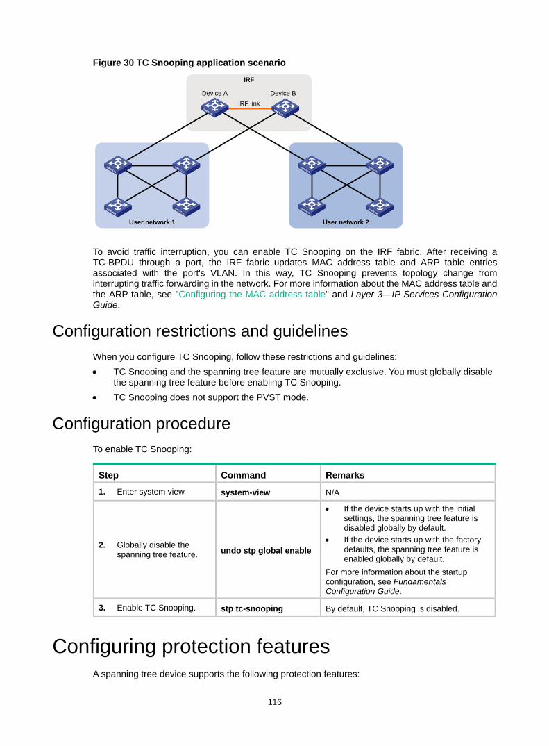
116
Figure 30 TC Snooping application scenario
To avoid traffic interruption, you can enable TC Snooping on the IRF fabric. After receiving a TC-BPDU through a port, the IRF fabric updates MAC address table and ARP table entries associated with the port's VLAN. In this way, TC Snooping prevents topology change from interrupting traffic forwarding in the network. For more information about the MAC address table and the ARP table, see "Configuring the MAC address table" and Layer 3—IP Services Configuration Guide.
Configuration restrictions and guidelines When you configure TC Snooping, follow these restrictions and guidelines: • TC Snooping and the spanning tree feature are mutually exclusive. You must globally disable
the spanning tree feature before enabling TC Snooping. • TC Snooping does not support the PVST mode.
Configuration procedure To enable TC Snooping:
Step Command Remarks 1. Enter system view. system-view N/A
2. Globally disable the spanning tree feature. undo stp global enable
• If the device starts up with the initial settings, the spanning tree feature is disabled globally by default.
• If the device starts up with the factory defaults, the spanning tree feature is enabled globally by default.
For more information about the startup configuration, see Fundamentals Configuration Guide.
3. Enable TC Snooping. stp tc-snooping By default, TC Snooping is disabled.
Configuring protection features A spanning tree device supports the following protection features:
User network 1 User network 2
IRF
Device A Device BIRF link
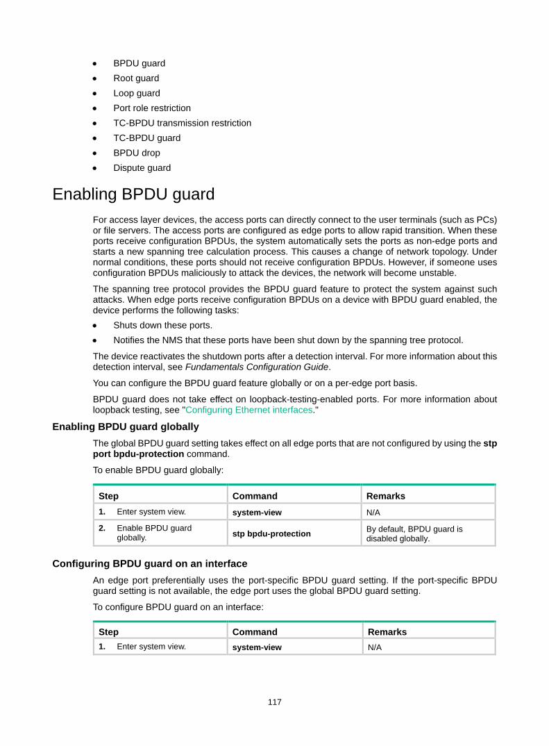
117
• BPDU guard • Root guard • Loop guard • Port role restriction • TC-BPDU transmission restriction • TC-BPDU guard • BPDU drop • Dispute guard
Enabling BPDU guard For access layer devices, the access ports can directly connect to the user terminals (such as PCs) or file servers. The access ports are configured as edge ports to allow rapid transition. When these ports receive configuration BPDUs, the system automatically sets the ports as non-edge ports and starts a new spanning tree calculation process. This causes a change of network topology. Under normal conditions, these ports should not receive configuration BPDUs. However, if someone uses configuration BPDUs maliciously to attack the devices, the network will become unstable.
The spanning tree protocol provides the BPDU guard feature to protect the system against such attacks. When edge ports receive configuration BPDUs on a device with BPDU guard enabled, the device performs the following tasks: • Shuts down these ports. • Notifies the NMS that these ports have been shut down by the spanning tree protocol.
The device reactivates the shutdown ports after a detection interval. For more information about this detection interval, see Fundamentals Configuration Guide.
You can configure the BPDU guard feature globally or on a per-edge port basis.
BPDU guard does not take effect on loopback-testing-enabled ports. For more information about loopback testing, see "Configuring Ethernet interfaces."
Enabling BPDU guard globally The global BPDU guard setting takes effect on all edge ports that are not configured by using the stp port bpdu-protection command.
To enable BPDU guard globally:
Step Command Remarks 1. Enter system view. system-view N/A
2. Enable BPDU guard globally. stp bpdu-protection By default, BPDU guard is
disabled globally.
Configuring BPDU guard on an interface An edge port preferentially uses the port-specific BPDU guard setting. If the port-specific BPDU guard setting is not available, the edge port uses the global BPDU guard setting.
To configure BPDU guard on an interface:
Step Command Remarks 1. Enter system view. system-view N/A
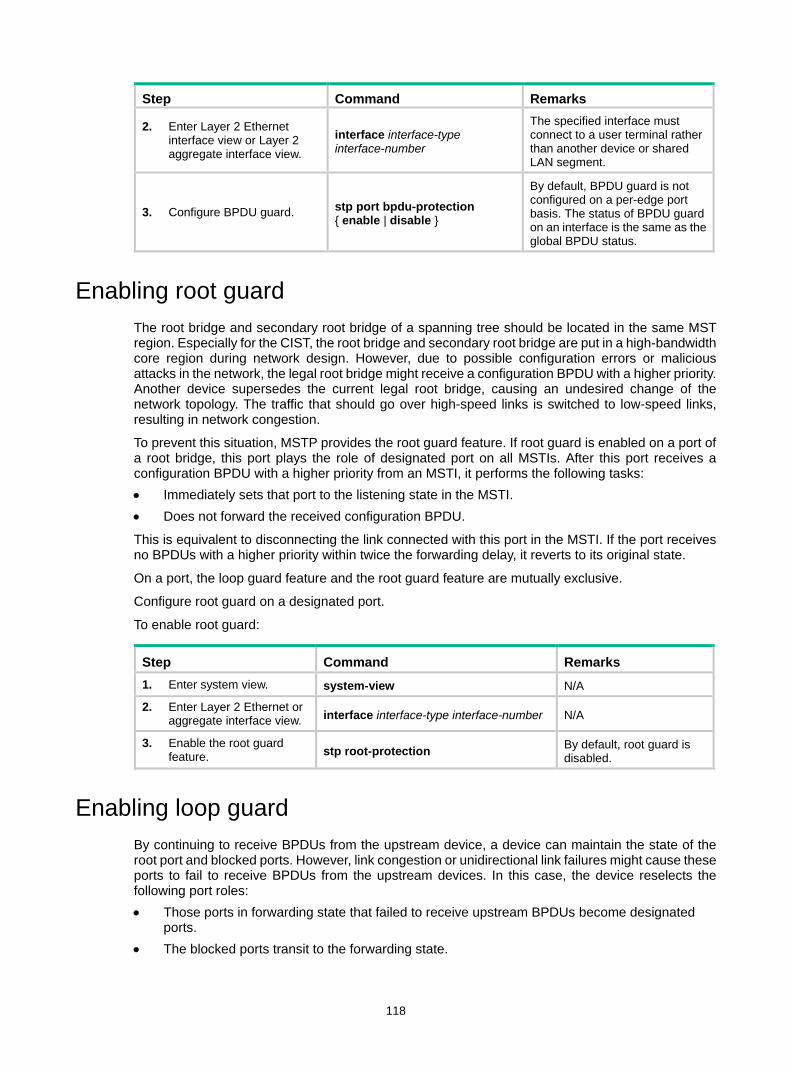
118
Step Command Remarks
2. Enter Layer 2 Ethernet interface view or Layer 2 aggregate interface view.
interface interface-type interface-number
The specified interface must connect to a user terminal rather than another device or shared LAN segment.
3. Configure BPDU guard. stp port bpdu-protection { enable | disable }
By default, BPDU guard is not configured on a per-edge port basis. The status of BPDU guard on an interface is the same as the global BPDU status.
Enabling root guard The root bridge and secondary root bridge of a spanning tree should be located in the same MST region. Especially for the CIST, the root bridge and secondary root bridge are put in a high-bandwidth core region during network design. However, due to possible configuration errors or malicious attacks in the network, the legal root bridge might receive a configuration BPDU with a higher priority. Another device supersedes the current legal root bridge, causing an undesired change of the network topology. The traffic that should go over high-speed links is switched to low-speed links, resulting in network congestion.
To prevent this situation, MSTP provides the root guard feature. If root guard is enabled on a port of a root bridge, this port plays the role of designated port on all MSTIs. After this port receives a configuration BPDU with a higher priority from an MSTI, it performs the following tasks: • Immediately sets that port to the listening state in the MSTI. • Does not forward the received configuration BPDU.
This is equivalent to disconnecting the link connected with this port in the MSTI. If the port receives no BPDUs with a higher priority within twice the forwarding delay, it reverts to its original state.
On a port, the loop guard feature and the root guard feature are mutually exclusive.
Configure root guard on a designated port.
To enable root guard:
Step Command Remarks 1. Enter system view. system-view N/A
2. Enter Layer 2 Ethernet or aggregate interface view. interface interface-type interface-number N/A
3. Enable the root guard feature. stp root-protection By default, root guard is
disabled.
Enabling loop guard By continuing to receive BPDUs from the upstream device, a device can maintain the state of the root port and blocked ports. However, link congestion or unidirectional link failures might cause these ports to fail to receive BPDUs from the upstream devices. In this case, the device reselects the following port roles: • Those ports in forwarding state that failed to receive upstream BPDUs become designated
ports. • The blocked ports transit to the forwarding state.

119
As a result, loops occur in the switched network. The loop guard feature can suppress the occurrence of such loops.
The initial state of a loop guard-enabled port is discarding in every MSTI. When the port receives BPDUs, it transits its state. Otherwise, it stays in the discarding state to prevent temporary loops.
Do not enable loop guard on a port that connects user terminals. Otherwise, the port stays in the discarding state in all MSTIs because it cannot receive BPDUs.
On a port, the loop guard feature is mutually exclusive with the root guard feature or the edge port setting.
Configure loop guard on the root port and alternate ports of a device.
To enable loop guard:
Step Command Remarks 1. Enter system view. system-view N/A
2. Enter Layer 2 Ethernet or aggregate interface view. interface interface-type interface-number N/A
3. Enable the loop guard feature for the ports. stp loop-protection By default, loop guard is
disabled.
Configuring port role restriction
CAUTION: Use this feature with caution, because enabling port role restriction on a port might affect the connectivity of the spanning tree topology.
The change to the bridge ID of a device in the user access network might cause a change to the spanning tree topology in the core network. To avoid this problem, you can enable port role restriction on a port. With this feature enabled, when the port receives a superior BPDU, it becomes an alternate port rather than a root port.
Make this configuration on the port that connects to the user access network.
To configure port role restriction:
Step Command Remarks 1. Enter system view. system-view N/A
2. Enter Layer 2 Ethernet or aggregate interface view.
interface interface-type interface-number N/A
3. Enable port role restriction. stp role-restriction By default, port role restriction is disabled.
Configuring TC-BPDU transmission restriction
CAUTION: Enabling TC-BPDU transmission restriction on a port might cause the previous forwarding address table to fail to be updated when the topology changes.
The topology change to the user access network might cause the forwarding address changes to the core network. When the user access network topology is unstable, the user access network might affect the core network. To avoid this problem, you can enable TC-BPDU transmission restriction on
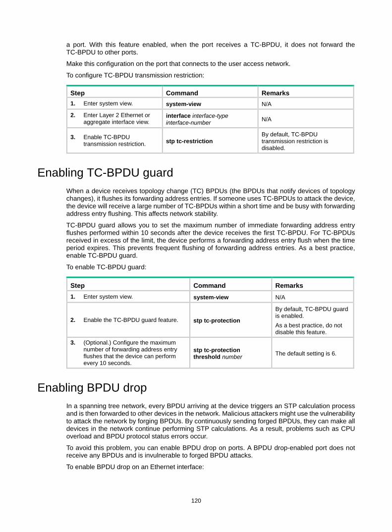
120
a port. With this feature enabled, when the port receives a TC-BPDU, it does not forward the TC-BPDU to other ports.
Make this configuration on the port that connects to the user access network.
To configure TC-BPDU transmission restriction:
Step Command Remarks 1. Enter system view. system-view N/A
2. Enter Layer 2 Ethernet or aggregate interface view.
interface interface-type interface-number N/A
3. Enable TC-BPDU transmission restriction. stp tc-restriction
By default, TC-BPDU transmission restriction is disabled.
Enabling TC-BPDU guard When a device receives topology change (TC) BPDUs (the BPDUs that notify devices of topology changes), it flushes its forwarding address entries. If someone uses TC-BPDUs to attack the device, the device will receive a large number of TC-BPDUs within a short time and be busy with forwarding address entry flushing. This affects network stability.
TC-BPDU guard allows you to set the maximum number of immediate forwarding address entry flushes performed within 10 seconds after the device receives the first TC-BPDU. For TC-BPDUs received in excess of the limit, the device performs a forwarding address entry flush when the time period expires. This prevents frequent flushing of forwarding address entries. As a best practice, enable TC-BPDU guard.
To enable TC-BPDU guard:
Step Command Remarks 1. Enter system view. system-view N/A
2. Enable the TC-BPDU guard feature. stp tc-protection
By default, TC-BPDU guard is enabled. As a best practice, do not disable this feature.
3. (Optional.) Configure the maximum number of forwarding address entry flushes that the device can perform every 10 seconds.
stp tc-protection threshold number The default setting is 6.
Enabling BPDU drop In a spanning tree network, every BPDU arriving at the device triggers an STP calculation process and is then forwarded to other devices in the network. Malicious attackers might use the vulnerability to attack the network by forging BPDUs. By continuously sending forged BPDUs, they can make all devices in the network continue performing STP calculations. As a result, problems such as CPU overload and BPDU protocol status errors occur.
To avoid this problem, you can enable BPDU drop on ports. A BPDU drop-enabled port does not receive any BPDUs and is invulnerable to forged BPDU attacks.
To enable BPDU drop on an Ethernet interface:

121
Step Command Remarks 1. Enter system view. system-view N/A
2. Enter Layer 2 Ethernet interface view.
interface interface-type interface-number N/A
3. Enable BPDU drop on the current interface. bpdu-drop any By default, BPDU drop is
disabled.
Enabling dispute guard Dispute guard can be triggered by unidirectional link failures. If an upstream port receives inferior BPDUs from a downstream designated port in forwarding or learning state because of a unidirectional link failure, a loop appears. Dispute guard blocks the upstream designated port to prevent the loop.
Dispute guard is enabled by default. You don't have to configure this feature.
As shown in Figure 31, in normal conditions, the spanning tree calculation result is as follows: • Device A is the root bridge, and Port A1 is a designated port. • Port B1 is blocked.
When the link between Port A1 and Port B1 fails in the direction of Port A1 to Port B1 and becomes unidirectional, the following events occur: 1. Port A1 can only receive BPDUs and cannot send BPDUs to Port B1. 2. Port B1 does not receive BPDUs from Port A1 for a certain period of time. 3. Device B determines itself as the root bridge. 4. Port B1 sends its BPDUs to Port A1. 5. Port A1 determines the received BPDUs are inferior to its own BPDUs. A dispute is detected. 6. Dispute guard is triggered and blocks Port A1 to prevent a loop.
Figure 31 Dispute guard triggering scenario
Device A
Device B
Root
Root port
Designated port
Normal link
Blocked link
Blocked port
Port A1 Port A2
Port B1 Port B2
Device A
Device B
Root
Port A1 Port A2
Port B1 Port B2
Normal condition Unidirectional link occurs
Device A
Device B
Root
Port A1
Port B1 Port B2
Dispute guard is triggered
Port A2
Unidirectional link

122
Disabling the device to reactivate the shutdown edge ports
A device enabled with BPDU guard shuts down edge ports that have received configuration BPDUs and notifies the NMS of the shutdown event. After a port status detection interval, the device reactivates the shutdown ports. This feature allows you to disable the device to reactivate the shutdown ports. The feature applies to edge ports that are shut down after you configure the stp port shutdown permanent command. To bring up these ports, use the undo shutdown command.
For more information about the port status detection interval, see device management configuration in Fundamentals Configuration Guide.
To disable the device to reactivate the shutdown edge ports:
Step Command Remarks 1. Enter system view. system-view N/A
2. Disable the device to reactivate the shutdown edge ports.
stp port shutdown permanent By default, a device reactivates the shutdown edge ports after a port status detection interval.
Enabling BPDU transparent transmission on a port
Perform this task to enable a port to transmit BPDUs transparently. Whether the spanning tree protocols are enabled on a port does not affect the BPDU transparent transmission feature.
When a port is enabled with BPDU transparent transmission, its downstream port can receive the BPDUs generated by that port. This might cause network flapping. Before you enable BPDU transparent transmission on a port, disable the spanning tree protocols on that port as a best practice.
To enable transparent transmission on a port:
Step Command Remarks 1. Enter system view. system-view N/A
2. Enter Layer 2 Ethernet or aggregate interface view.
interface interface-type interface-number N/A
3. Enable BPDU transparent transmission. stp transparent enable
By default, the BPDU transparent transmission feature is disabled on a port.
Enabling SNMP notifications for new-root election and topology change events
This feature enables the device to generate logs and report new-root election events or spanning tree topology changes to SNMP. For the event notifications to be sent correctly, you must also configure SNMP on the device. For more information about SNMP configuration, see the network management and monitoring configuration guide for the device.
When you use the snmp-agent trap enable stp [ new-root | tc ] command, follow these guidelines:
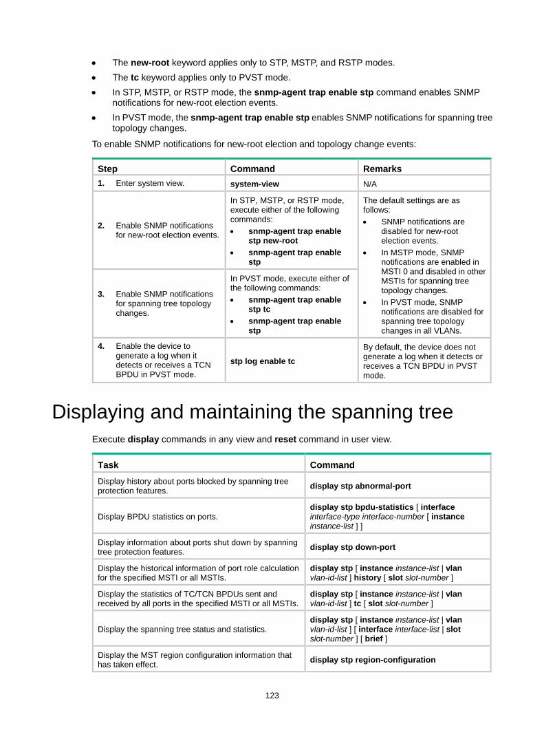
123
• The new-root keyword applies only to STP, MSTP, and RSTP modes. • The tc keyword applies only to PVST mode. • In STP, MSTP, or RSTP mode, the snmp-agent trap enable stp command enables SNMP
notifications for new-root election events. • In PVST mode, the snmp-agent trap enable stp enables SNMP notifications for spanning tree
topology changes.
To enable SNMP notifications for new-root election and topology change events:
Step Command Remarks 1. Enter system view. system-view N/A
2. Enable SNMP notifications for new-root election events.
In STP, MSTP, or RSTP mode, execute either of the following commands: • snmp-agent trap enable
stp new-root • snmp-agent trap enable
stp
The default settings are as follows: • SNMP notifications are
disabled for new-root election events.
• In MSTP mode, SNMP notifications are enabled in MSTI 0 and disabled in other MSTIs for spanning tree topology changes.
• In PVST mode, SNMP notifications are disabled for spanning tree topology changes in all VLANs.
3. Enable SNMP notifications for spanning tree topology changes.
In PVST mode, execute either of the following commands: • snmp-agent trap enable
stp tc • snmp-agent trap enable
stp
4. Enable the device to generate a log when it detects or receives a TCN BPDU in PVST mode.
stp log enable tc By default, the device does not generate a log when it detects or receives a TCN BPDU in PVST mode.
Displaying and maintaining the spanning tree Execute display commands in any view and reset command in user view.
Task Command Display history about ports blocked by spanning tree protection features. display stp abnormal-port
Display BPDU statistics on ports. display stp bpdu-statistics [ interface interface-type interface-number [ instance instance-list ] ]
Display information about ports shut down by spanning tree protection features. display stp down-port
Display the historical information of port role calculation for the specified MSTI or all MSTIs.
display stp [ instance instance-list | vlan vlan-id-list ] history [ slot slot-number ]
Display the statistics of TC/TCN BPDUs sent and received by all ports in the specified MSTI or all MSTIs.
display stp [ instance instance-list | vlan vlan-id-list ] tc [ slot slot-number ]
Display the spanning tree status and statistics. display stp [ instance instance-list | vlan vlan-id-list ] [ interface interface-list | slot slot-number ] [ brief ]
Display the MST region configuration information that has taken effect. display stp region-configuration

124
Task Command
Display the root bridge information of all MSTIs. display stp root
Clear the spanning tree statistics. reset stp [ interface interface-list ]
Spanning tree configuration example MSTP configuration example Network requirements
As shown in Figure 32, all devices on the network are in the same MST region. Device A and Device B work at the distribution layer. Device C and Device D work at the access layer.
Configure MSTP so that packets of different VLANs are forwarded along different spanning trees. • VLAN 10 packets are forwarded along MSTI 1. • VLAN 30 packets are forwarded along MSTI 3. • VLAN 40 packets are forwarded along MSTI 4. • VLAN 20 packets are forwarded along MSTI 0.
VLAN 10 and VLAN 30 are terminated on the distribution layer devices, and VLAN 40 is terminated on the access layer devices. The root bridges of MSTI 1 and MSTI 3 are Device A and Device B, respectively, and the root bridge of MSTI 4 is Device C.
Figure 32 Network diagram
Configuration procedure 1. Configure VLANs and VLAN member ports. (Details not shown.)
Create VLAN 10, VLAN 20, and VLAN 30 on both Device A and Device B. Create VLAN 10, VLAN 20, and VLAN 40 on Device C. Create VLAN 20, VLAN 30, and VLAN 40 on Device D. Configure the ports on these devices as trunk ports and assign them to related VLANs.
2. Configure Device A: # Enter MST region view, and configure the MST region name as example.
MST region
Permit: all VLANs
Permit: VLANs 20 and 30Permit: VLANs 10 and 20
Permit: VLANs 20 and 40
Permit: VLANs 20 and 30
Permit: VLANs 10 and 20
Device A Device B
Device C Device D
FGE1/0/3
FGE1/0/2
FGE1
/0/1
FGE1/0/3
FGE1/0/2
FGE1/0/1
FGE1
/0/1
FGE1/0/1
FGE1/0/3 FGE1/0/3FGE1/0/2 FGE1/0/2
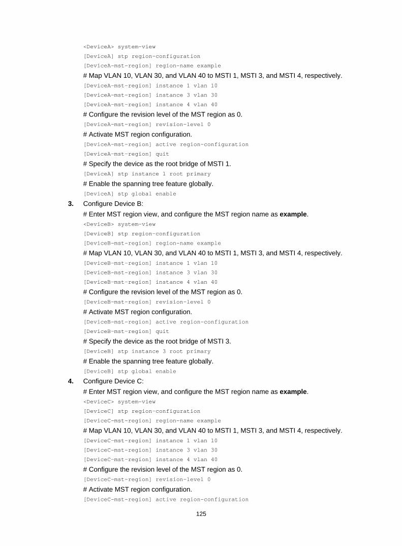
125
<DeviceA> system-view
[DeviceA] stp region-configuration
[DeviceA-mst-region] region-name example
# Map VLAN 10, VLAN 30, and VLAN 40 to MSTI 1, MSTI 3, and MSTI 4, respectively. [DeviceA-mst-region] instance 1 vlan 10
[DeviceA-mst-region] instance 3 vlan 30
[DeviceA-mst-region] instance 4 vlan 40
# Configure the revision level of the MST region as 0. [DeviceA-mst-region] revision-level 0
# Activate MST region configuration. [DeviceA-mst-region] active region-configuration
[DeviceA-mst-region] quit
# Specify the device as the root bridge of MSTI 1. [DeviceA] stp instance 1 root primary
# Enable the spanning tree feature globally. [DeviceA] stp global enable
3. Configure Device B: # Enter MST region view, and configure the MST region name as example. <DeviceB> system-view
[DeviceB] stp region-configuration
[DeviceB-mst-region] region-name example
# Map VLAN 10, VLAN 30, and VLAN 40 to MSTI 1, MSTI 3, and MSTI 4, respectively. [DeviceB-mst-region] instance 1 vlan 10
[DeviceB-mst-region] instance 3 vlan 30
[DeviceB-mst-region] instance 4 vlan 40
# Configure the revision level of the MST region as 0. [DeviceB-mst-region] revision-level 0
# Activate MST region configuration. [DeviceB-mst-region] active region-configuration
[DeviceB-mst-region] quit
# Specify the device as the root bridge of MSTI 3. [DeviceB] stp instance 3 root primary
# Enable the spanning tree feature globally. [DeviceB] stp global enable
4. Configure Device C: # Enter MST region view, and configure the MST region name as example. <DeviceC> system-view
[DeviceC] stp region-configuration
[DeviceC-mst-region] region-name example
# Map VLAN 10, VLAN 30, and VLAN 40 to MSTI 1, MSTI 3, and MSTI 4, respectively. [DeviceC-mst-region] instance 1 vlan 10
[DeviceC-mst-region] instance 3 vlan 30
[DeviceC-mst-region] instance 4 vlan 40
# Configure the revision level of the MST region as 0. [DeviceC-mst-region] revision-level 0
# Activate MST region configuration. [DeviceC-mst-region] active region-configuration
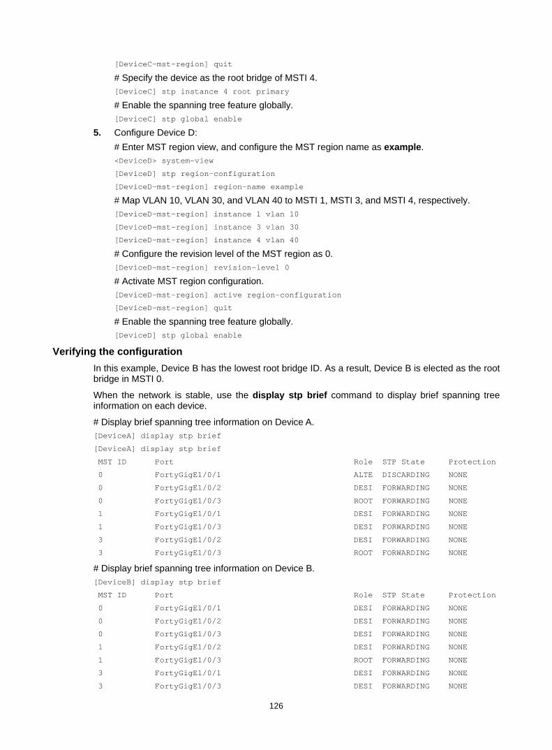
126
[DeviceC-mst-region] quit
# Specify the device as the root bridge of MSTI 4. [DeviceC] stp instance 4 root primary
# Enable the spanning tree feature globally. [DeviceC] stp global enable
5. Configure Device D: # Enter MST region view, and configure the MST region name as example. <DeviceD> system-view
[DeviceD] stp region-configuration
[DeviceD-mst-region] region-name example
# Map VLAN 10, VLAN 30, and VLAN 40 to MSTI 1, MSTI 3, and MSTI 4, respectively. [DeviceD-mst-region] instance 1 vlan 10
[DeviceD-mst-region] instance 3 vlan 30
[DeviceD-mst-region] instance 4 vlan 40
# Configure the revision level of the MST region as 0. [DeviceD-mst-region] revision-level 0
# Activate MST region configuration. [DeviceD-mst-region] active region-configuration
[DeviceD-mst-region] quit
# Enable the spanning tree feature globally. [DeviceD] stp global enable
Verifying the configuration In this example, Device B has the lowest root bridge ID. As a result, Device B is elected as the root bridge in MSTI 0.
When the network is stable, use the display stp brief command to display brief spanning tree information on each device.
# Display brief spanning tree information on Device A. [DeviceA] display stp brief
[DeviceA] display stp brief
MST ID Port Role STP State Protection
0 FortyGigE1/0/1 ALTE DISCARDING NONE
0 FortyGigE1/0/2 DESI FORWARDING NONE
0 FortyGigE1/0/3 ROOT FORWARDING NONE
1 FortyGigE1/0/1 DESI FORWARDING NONE
1 FortyGigE1/0/3 DESI FORWARDING NONE
3 FortyGigE1/0/2 DESI FORWARDING NONE
3 FortyGigE1/0/3 ROOT FORWARDING NONE
# Display brief spanning tree information on Device B. [DeviceB] display stp brief
MST ID Port Role STP State Protection
0 FortyGigE1/0/1 DESI FORWARDING NONE
0 FortyGigE1/0/2 DESI FORWARDING NONE
0 FortyGigE1/0/3 DESI FORWARDING NONE
1 FortyGigE1/0/2 DESI FORWARDING NONE
1 FortyGigE1/0/3 ROOT FORWARDING NONE
3 FortyGigE1/0/1 DESI FORWARDING NONE
3 FortyGigE1/0/3 DESI FORWARDING NONE
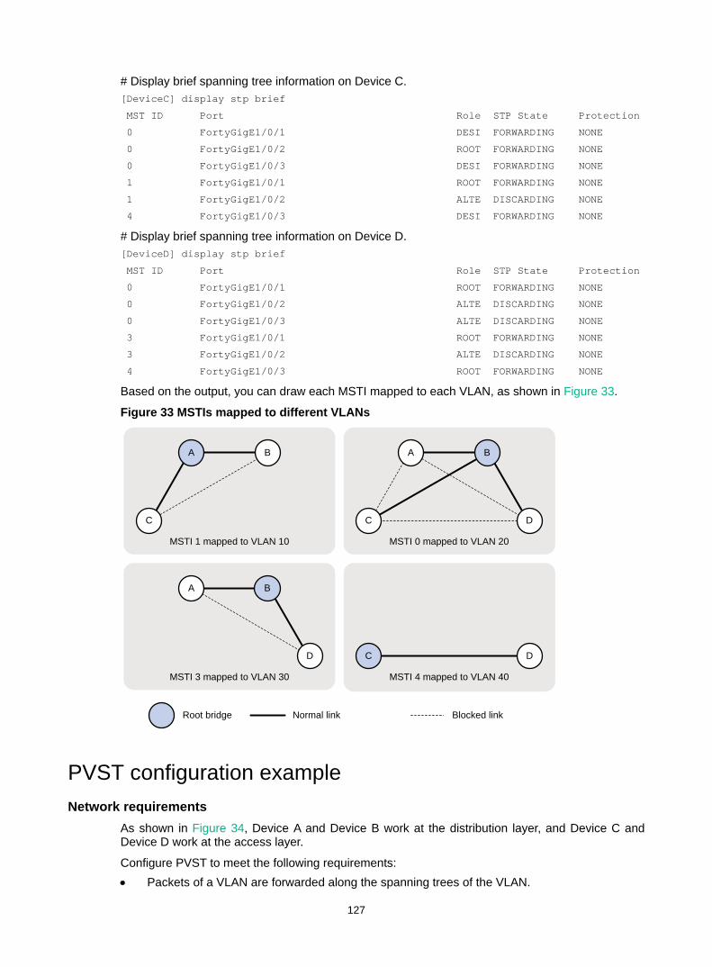
127
# Display brief spanning tree information on Device C. [DeviceC] display stp brief
MST ID Port Role STP State Protection
0 FortyGigE1/0/1 DESI FORWARDING NONE
0 FortyGigE1/0/2 ROOT FORWARDING NONE
0 FortyGigE1/0/3 DESI FORWARDING NONE
1 FortyGigE1/0/1 ROOT FORWARDING NONE
1 FortyGigE1/0/2 ALTE DISCARDING NONE
4 FortyGigE1/0/3 DESI FORWARDING NONE
# Display brief spanning tree information on Device D. [DeviceD] display stp brief
MST ID Port Role STP State Protection
0 FortyGigE1/0/1 ROOT FORWARDING NONE
0 FortyGigE1/0/2 ALTE DISCARDING NONE
0 FortyGigE1/0/3 ALTE DISCARDING NONE
3 FortyGigE1/0/1 ROOT FORWARDING NONE
3 FortyGigE1/0/2 ALTE DISCARDING NONE
4 FortyGigE1/0/3 ROOT FORWARDING NONE
Based on the output, you can draw each MSTI mapped to each VLAN, as shown in Figure 33.
Figure 33 MSTIs mapped to different VLANs
PVST configuration example Network requirements
As shown in Figure 34, Device A and Device B work at the distribution layer, and Device C and Device D work at the access layer.
Configure PVST to meet the following requirements: • Packets of a VLAN are forwarded along the spanning trees of the VLAN.
A
B
A B
C D
C
B
C
MSTI 1 mapped to VLAN 10
A
D D
Root bridge Normal link Blocked link
MSTI 3 mapped to VLAN 30
MSTI 0 mapped to VLAN 20
MSTI 4 mapped to VLAN 40
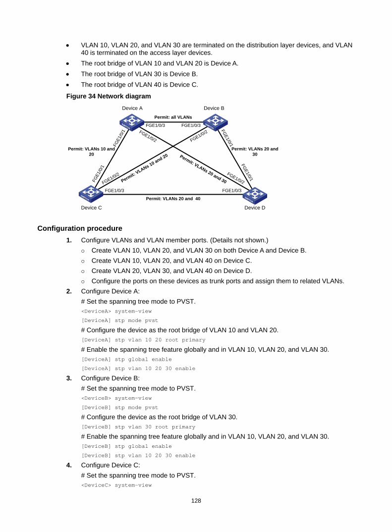
128
• VLAN 10, VLAN 20, and VLAN 30 are terminated on the distribution layer devices, and VLAN 40 is terminated on the access layer devices.
• The root bridge of VLAN 10 and VLAN 20 is Device A. • The root bridge of VLAN 30 is Device B. • The root bridge of VLAN 40 is Device C.
Figure 34 Network diagram
Configuration procedure 1. Configure VLANs and VLAN member ports. (Details not shown.)
Create VLAN 10, VLAN 20, and VLAN 30 on both Device A and Device B. Create VLAN 10, VLAN 20, and VLAN 40 on Device C. Create VLAN 20, VLAN 30, and VLAN 40 on Device D. Configure the ports on these devices as trunk ports and assign them to related VLANs.
2. Configure Device A: # Set the spanning tree mode to PVST. <DeviceA> system-view
[DeviceA] stp mode pvst
# Configure the device as the root bridge of VLAN 10 and VLAN 20. [DeviceA] stp vlan 10 20 root primary
# Enable the spanning tree feature globally and in VLAN 10, VLAN 20, and VLAN 30. [DeviceA] stp global enable
[DeviceA] stp vlan 10 20 30 enable
3. Configure Device B: # Set the spanning tree mode to PVST. <DeviceB> system-view
[DeviceB] stp mode pvst
# Configure the device as the root bridge of VLAN 30. [DeviceB] stp vlan 30 root primary
# Enable the spanning tree feature globally and in VLAN 10, VLAN 20, and VLAN 30. [DeviceB] stp global enable
[DeviceB] stp vlan 10 20 30 enable
4. Configure Device C: # Set the spanning tree mode to PVST. <DeviceC> system-view
Permit: all VLANs
Permit: VLANs 20 and 30Permit: VLANs 10 and 20
Permit: VLANs 20 and 40
Permit: VLANs 20 and 30
Permit: VLANs 10 and 20
Device A Device B
Device C Device D
FGE1/0/3
FGE1/0/2
FGE1
/0/1
FGE1/0/3
FGE1/0/2
FGE1/0/1
FGE1
/0/1
FGE1/0/1
FGE1/0/3 FGE1/0/3FGE1/0/2 FGE1/0/2
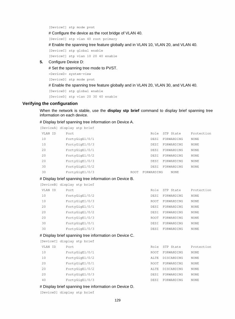
129
[DeviceC] stp mode pvst
# Configure the device as the root bridge of VLAN 40. [DeviceC] stp vlan 40 root primary
# Enable the spanning tree feature globally and in VLAN 10, VLAN 20, and VLAN 40. [DeviceC] stp global enable
[DeviceC] stp vlan 10 20 40 enable
5. Configure Device D: # Set the spanning tree mode to PVST. <DeviceD> system-view
[DeviceD] stp mode pvst
# Enable the spanning tree feature globally and in VLAN 20, VLAN 30, and VLAN 40. [DeviceD] stp global enable
[DeviceD] stp vlan 20 30 40 enable
Verifying the configuration When the network is stable, use the display stp brief command to display brief spanning tree information on each device.
# Display brief spanning tree information on Device A. [DeviceA] display stp brief
VLAN ID Port Role STP State Protection
10 FortyGigE1/0/1 DESI FORWARDING NONE
10 FortyGigE1/0/3 DESI FORWARDING NONE
20 FortyGigE1/0/1 DESI FORWARDING NONE
20 FortyGigE1/0/2 DESI FORWARDING NONE
20 FortyGigE1/0/3 DESI FORWARDING NONE
30 FortyGigE1/0/2 DESI FORWARDING NONE
30 FortyGigE1/0/3 ROOT FORWARDING NONE
# Display brief spanning tree information on Device B. [DeviceB] display stp brief
VLAN ID Port Role STP State Protection
10 FortyGigE1/0/2 DESI FORWARDING NONE
10 FortyGigE1/0/3 ROOT FORWARDING NONE
20 FortyGigE1/0/1 DESI FORWARDING NONE
20 FortyGigE1/0/2 DESI FORWARDING NONE
20 FortyGigE1/0/3 ROOT FORWARDING NONE
30 FortyGigE1/0/1 DESI FORWARDING NONE
30 FortyGigE1/0/3 DESI FORWARDING NONE
# Display brief spanning tree information on Device C. [DeviceC] display stp brief
VLAN ID Port Role STP State Protection
10 FortyGigE1/0/1 ROOT FORWARDING NONE
10 FortyGigE1/0/2 ALTE DISCARDING NONE
20 FortyGigE1/0/1 ROOT FORWARDING NONE
20 FortyGigE1/0/2 ALTE DISCARDING NONE
20 FortyGigE1/0/3 DESI FORWARDING NONE
40 FortyGigE1/0/3 DESI FORWARDING NONE
# Display brief spanning tree information on Device D. [DeviceD] display stp brief

130
VLAN ID Port Role STP State Protection
20 FortyGigE1/0/1 ALTE DISCARDING NONE
20 FortyGigE1/0/2 ROOT FORWARDING NONE
20 FortyGigE1/0/3 ALTE DISCARDING NONE
30 FortyGigE1/0/1 ROOT FORWARDING NONE
30 FortyGigE1/0/2 ALTE DISCARDING NONE
40 FortyGigE1/0/3 ROOT FORWARDING NONE
Based on the output, you can draw a topology for each VLAN spanning tree, as shown in Figure 35.
Figure 35 VLAN spanning tree topologies
A
B
B
C D
C
B
C
Spanning tree for VLAN 10
A
D D
Root bridge Normal link Blocked link
Spanning tree for VLAN 30 Spanning tree for VLAN 40
A
Spanning tree for VLAN 20
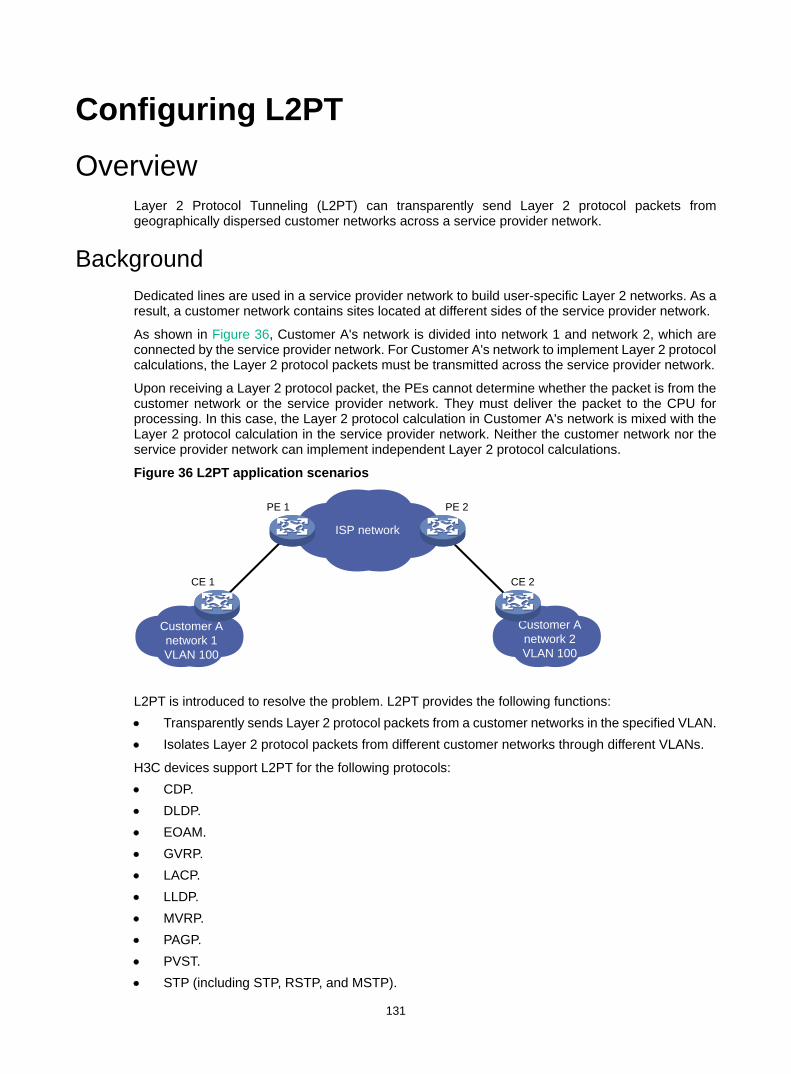
131
Configuring L2PT Overview
Layer 2 Protocol Tunneling (L2PT) can transparently send Layer 2 protocol packets from geographically dispersed customer networks across a service provider network.
Background Dedicated lines are used in a service provider network to build user-specific Layer 2 networks. As a result, a customer network contains sites located at different sides of the service provider network.
As shown in Figure 36, Customer A's network is divided into network 1 and network 2, which are connected by the service provider network. For Customer A's network to implement Layer 2 protocol calculations, the Layer 2 protocol packets must be transmitted across the service provider network.
Upon receiving a Layer 2 protocol packet, the PEs cannot determine whether the packet is from the customer network or the service provider network. They must deliver the packet to the CPU for processing. In this case, the Layer 2 protocol calculation in Customer A's network is mixed with the Layer 2 protocol calculation in the service provider network. Neither the customer network nor the service provider network can implement independent Layer 2 protocol calculations.
Figure 36 L2PT application scenarios
L2PT is introduced to resolve the problem. L2PT provides the following functions: • Transparently sends Layer 2 protocol packets from a customer networks in the specified VLAN. • Isolates Layer 2 protocol packets from different customer networks through different VLANs.
H3C devices support L2PT for the following protocols: • CDP. • DLDP. • EOAM. • GVRP. • LACP. • LLDP. • MVRP. • PAGP. • PVST. • STP (including STP, RSTP, and MSTP).
ISP network
Customer A network 1VLAN 100
Customer A network 2VLAN 100
CE 1 CE 2
PE 1 PE 2
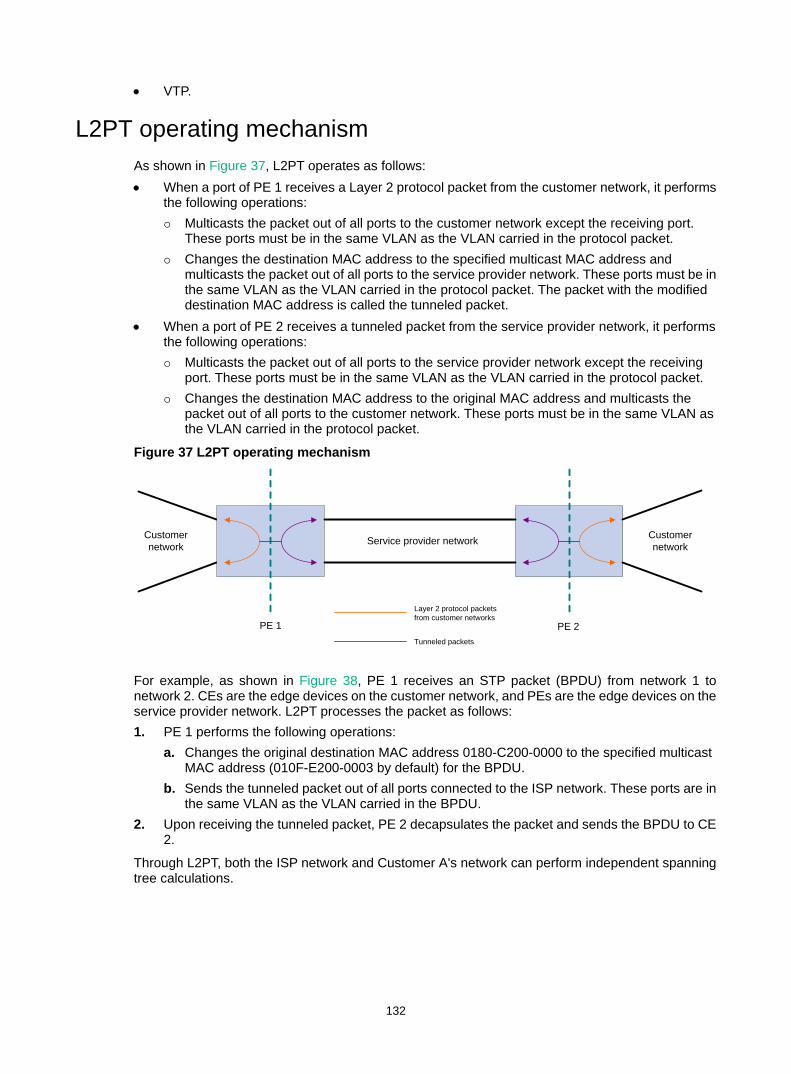
132
• VTP.
L2PT operating mechanism As shown in Figure 37, L2PT operates as follows: • When a port of PE 1 receives a Layer 2 protocol packet from the customer network, it performs
the following operations: Multicasts the packet out of all ports to the customer network except the receiving port.
These ports must be in the same VLAN as the VLAN carried in the protocol packet. Changes the destination MAC address to the specified multicast MAC address and
multicasts the packet out of all ports to the service provider network. These ports must be in the same VLAN as the VLAN carried in the protocol packet. The packet with the modified destination MAC address is called the tunneled packet.
• When a port of PE 2 receives a tunneled packet from the service provider network, it performs the following operations: Multicasts the packet out of all ports to the service provider network except the receiving
port. These ports must be in the same VLAN as the VLAN carried in the protocol packet. Changes the destination MAC address to the original MAC address and multicasts the
packet out of all ports to the customer network. These ports must be in the same VLAN as the VLAN carried in the protocol packet.
Figure 37 L2PT operating mechanism
For example, as shown in Figure 38, PE 1 receives an STP packet (BPDU) from network 1 to network 2. CEs are the edge devices on the customer network, and PEs are the edge devices on the service provider network. L2PT processes the packet as follows: 1. PE 1 performs the following operations:
a. Changes the original destination MAC address 0180-C200-0000 to the specified multicast MAC address (010F-E200-0003 by default) for the BPDU.
b. Sends the tunneled packet out of all ports connected to the ISP network. These ports are in the same VLAN as the VLAN carried in the BPDU.
2. Upon receiving the tunneled packet, PE 2 decapsulates the packet and sends the BPDU to CE 2.
Through L2PT, both the ISP network and Customer A's network can perform independent spanning tree calculations.
PE 1
Service provider network
PE 2
Customer network
Customer network
Layer 2 protocol packets from customer networks
Tunneled packets
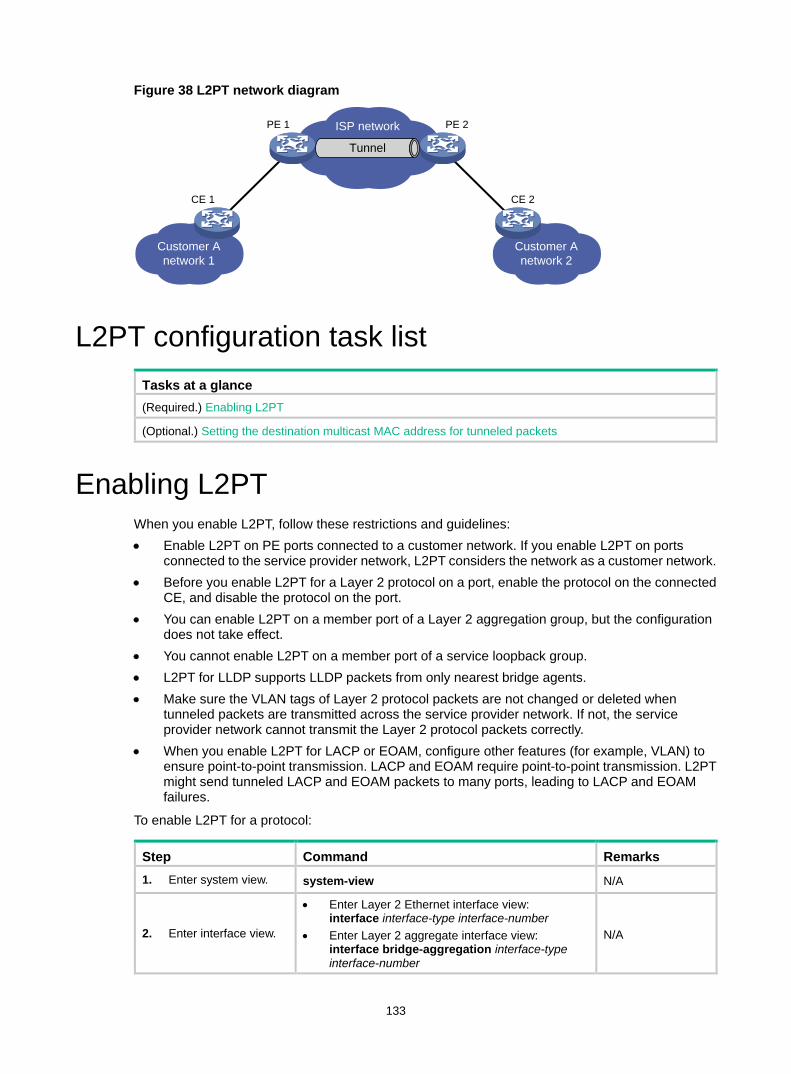
133
Figure 38 L2PT network diagram
L2PT configuration task list Tasks at a glance (Required.) Enabling L2PT
(Optional.) Setting the destination multicast MAC address for tunneled packets
Enabling L2PT When you enable L2PT, follow these restrictions and guidelines: • Enable L2PT on PE ports connected to a customer network. If you enable L2PT on ports
connected to the service provider network, L2PT considers the network as a customer network. • Before you enable L2PT for a Layer 2 protocol on a port, enable the protocol on the connected
CE, and disable the protocol on the port. • You can enable L2PT on a member port of a Layer 2 aggregation group, but the configuration
does not take effect. • You cannot enable L2PT on a member port of a service loopback group. • L2PT for LLDP supports LLDP packets from only nearest bridge agents. • Make sure the VLAN tags of Layer 2 protocol packets are not changed or deleted when
tunneled packets are transmitted across the service provider network. If not, the service provider network cannot transmit the Layer 2 protocol packets correctly.
• When you enable L2PT for LACP or EOAM, configure other features (for example, VLAN) to ensure point-to-point transmission. LACP and EOAM require point-to-point transmission. L2PT might send tunneled LACP and EOAM packets to many ports, leading to LACP and EOAM failures.
To enable L2PT for a protocol:
Step Command Remarks 1. Enter system view. system-view N/A
2. Enter interface view.
• Enter Layer 2 Ethernet interface view: interface interface-type interface-number
• Enter Layer 2 aggregate interface view: interface bridge-aggregation interface-type interface-number
N/A
ISP network
Customer A network 1
Customer A network 2
CE 1 CE 2
PE 1 PE 2
Tunnel
134
Step Command Remarks
3. Enable L2PT for a protocol.
• In Layer 2 Ethernet interface view: l2protocol { cdp | dldp | eoam | gvrp | lacp | lldp | mvrp | pagp | pvst | stp | vtp } tunnel dot1q
• In Layer 2 aggregate interface view: l2protocol { gvrp | mvrp | pvst | stp | vtp } tunnel dot1q
By default, L2PT is disabled.
Setting the destination multicast MAC address for tunneled packets
By default, the destination multicast MAC address for tunneled packets is 010F-E200-0003. You can change it to 0100-0CCD-CDD0, 0100-0CCD-CDD1, or 0100-0CCD-CDD2.
When you set the multicast destination MAC address for tunneled packets, follow these restrictions and guidelines: • For tunneled packets to be recognized, set the same destination multicast MAC addresses on
PEs that connected to the same customer network. • H3C recommends that you set different destination multicast MAC addresses on PEs
connected to different customer networks. It prevents L2PT from sending packets of a customer network to another customer network.
To set the destination multicast MAC address for tunneled packets:
Step Command Remarks 1. Enter system view. system-view N/A
2. Set the destination multicast MAC address for tunneled packets.
l2protocol tunnel-dmac mac-address By default, the multicast MAC address for tunneled packets is 010F-E200-0003.
Displaying and maintaining L2PT Execute display commands in any view and reset commands in user view.
Task Command
Display L2PT statistics. display l2protocol statistics [ interface interface-type interface-number ]
Clear L2PT statistics. reset l2protocol statistics [ interface interface-type interface-number ]
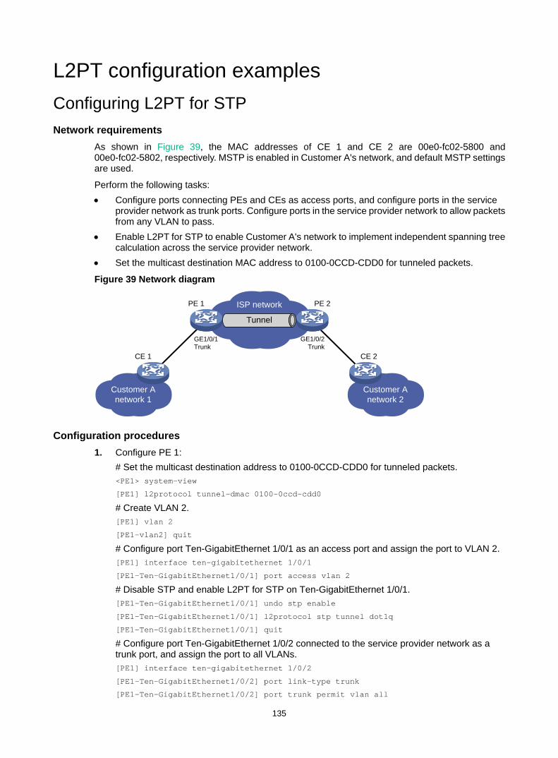
135
L2PT configuration examples Configuring L2PT for STP Network requirements
As shown in Figure 39, the MAC addresses of CE 1 and CE 2 are 00e0-fc02-5800 and 00e0-fc02-5802, respectively. MSTP is enabled in Customer A's network, and default MSTP settings are used.
Perform the following tasks: • Configure ports connecting PEs and CEs as access ports, and configure ports in the service
provider network as trunk ports. Configure ports in the service provider network to allow packets from any VLAN to pass.
• Enable L2PT for STP to enable Customer A's network to implement independent spanning tree calculation across the service provider network.
• Set the multicast destination MAC address to 0100-0CCD-CDD0 for tunneled packets.
Figure 39 Network diagram
Configuration procedures 1. Configure PE 1:
# Set the multicast destination address to 0100-0CCD-CDD0 for tunneled packets. <PE1> system-view
[PE1] l2protocol tunnel-dmac 0100-0ccd-cdd0
# Create VLAN 2. [PE1] vlan 2
[PE1-vlan2] quit
# Configure port Ten-GigabitEthernet 1/0/1 as an access port and assign the port to VLAN 2. [PE1] interface ten-gigabitethernet 1/0/1
[PE1-Ten-GigabitEthernet1/0/1] port access vlan 2
# Disable STP and enable L2PT for STP on Ten-GigabitEthernet 1/0/1. [PE1-Ten-GigabitEthernet1/0/1] undo stp enable
[PE1-Ten-GigabitEthernet1/0/1] l2protocol stp tunnel dot1q
[PE1-Ten-GigabitEthernet1/0/1] quit
# Configure port Ten-GigabitEthernet 1/0/2 connected to the service provider network as a trunk port, and assign the port to all VLANs. [PE1] interface ten-gigabitethernet 1/0/2
[PE1-Ten-GigabitEthernet1/0/2] port link-type trunk
[PE1-Ten-GigabitEthernet1/0/2] port trunk permit vlan all
ISP network
Tunnel
Customer A network 1
Customer A network 2
CE 1 CE 2
PE 1 PE 2
GE1/0/1Trunk
GE1/0/2Trunk
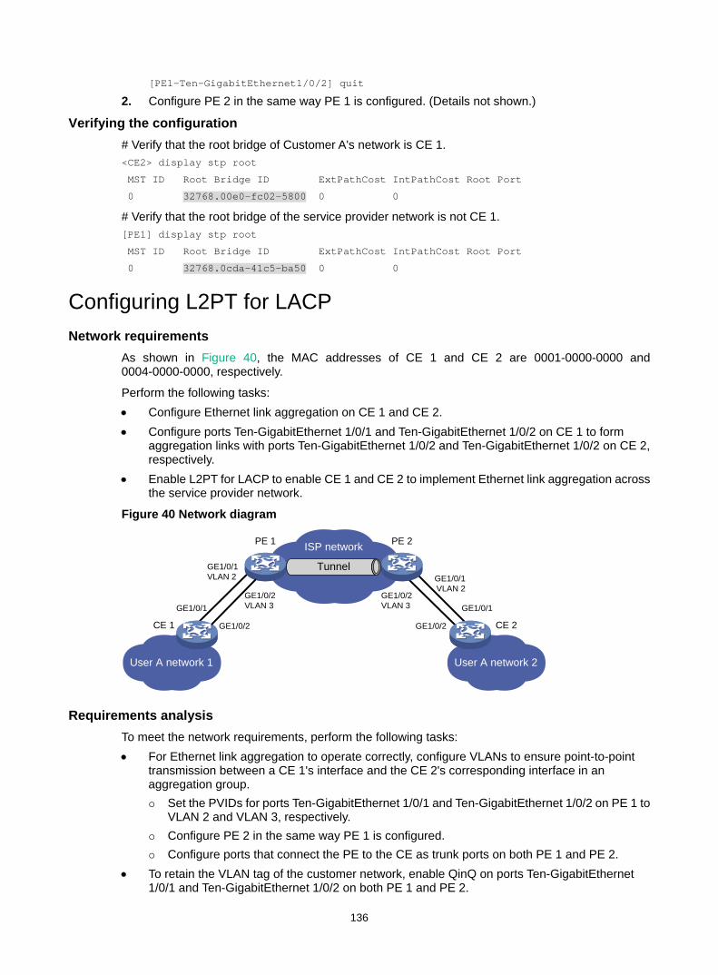
136
[PE1-Ten-GigabitEthernet1/0/2] quit
2. Configure PE 2 in the same way PE 1 is configured. (Details not shown.)
Verifying the configuration # Verify that the root bridge of Customer A's network is CE 1. <CE2> display stp root
MST ID Root Bridge ID ExtPathCost IntPathCost Root Port
0 32768.00e0-fc02-5800 0 0
# Verify that the root bridge of the service provider network is not CE 1. [PE1] display stp root
MST ID Root Bridge ID ExtPathCost IntPathCost Root Port
0 32768.0cda-41c5-ba50 0 0
Configuring L2PT for LACP Network requirements
As shown in Figure 40, the MAC addresses of CE 1 and CE 2 are 0001-0000-0000 and 0004-0000-0000, respectively.
Perform the following tasks: • Configure Ethernet link aggregation on CE 1 and CE 2. • Configure ports Ten-GigabitEthernet 1/0/1 and Ten-GigabitEthernet 1/0/2 on CE 1 to form
aggregation links with ports Ten-GigabitEthernet 1/0/2 and Ten-GigabitEthernet 1/0/2 on CE 2, respectively.
• Enable L2PT for LACP to enable CE 1 and CE 2 to implement Ethernet link aggregation across the service provider network.
Figure 40 Network diagram
Requirements analysis To meet the network requirements, perform the following tasks: • For Ethernet link aggregation to operate correctly, configure VLANs to ensure point-to-point
transmission between a CE 1's interface and the CE 2's corresponding interface in an aggregation group. Set the PVIDs for ports Ten-GigabitEthernet 1/0/1 and Ten-GigabitEthernet 1/0/2 on PE 1 to
VLAN 2 and VLAN 3, respectively. Configure PE 2 in the same way PE 1 is configured. Configure ports that connect the PE to the CE as trunk ports on both PE 1 and PE 2.
• To retain the VLAN tag of the customer network, enable QinQ on ports Ten-GigabitEthernet 1/0/1 and Ten-GigabitEthernet 1/0/2 on both PE 1 and PE 2.
ISP network
Tunnel
User A network 1 User A network 2
CE 1 CE 2
PE 1 PE 2
GE1/0/1VLAN 2 GE1/0/1
VLAN 2
GE1/0/1GE1/0/2VLAN 3
GE1/0/2VLAN 3
GE1/0/2
GE1/0/1
GE1/0/2

137
• For packets from any VLAN to be transmitted, configure all ports in the service provider network as trunk ports.
Configuration procedures 1. Configure CE 1:
# Configure Layer 2 aggregation group Bridge-Aggregation 1 to operate in dynamic aggregation mode. <CE1> system-view
[CE1] interface bridge-aggregation 1
[CE1-Bridge-Aggregation1] port link-type access
[CE1-Bridge-Aggregation1] link-aggregation mode dynamic
[CE1-Bridge-Aggregation1] quit
# Assign Ten-GigabitEthernet 1/0/1 and Ten-GigabitEthernet 1/0/2 to Bridge-Aggregation 1. [CE1] interface ten-gigabitethernet 1/0/1
[CE1-Ten-GigabitEthernet1/0/1] port link-aggregation group 1
[CE1-Ten-GigabitEthernet1/0/1] quit
[CE1] interface ten-gigabitethernet 1/0/2
[CE1-Ten-GigabitEthernet1/0/2] port link-aggregation group 1
[CE1-Ten-GigabitEthernet1/0/2] quit
2. Configure CE 2 in the same way CE 1 is configured. (Details not shown.) 3. Configure PE 1:
# Create VLANs 2 and 3. <PE1> system-view
[PE1] vlan 2
[PE1-vlan2] quit
[PE1] vlan 3
[PE1-vlan3] quit
# Configure Ten-GigabitEthernet 1/0/1 as a trunk port, assign the port to VLAN 2, and set the PVID to VLAN 2. [PE1] interface ten-gigabitethernet 1/0/1
[PE1-Ten-GigabitEthernet1/0/1] port link-mode bridge
[PE1-Ten-GigabitEthernet1/0/1] port link-type trunk
[PE1-Ten-GigabitEthernet1/0/1] port trunk permit vlan 2
[PE1-Ten-GigabitEthernet1/0/1] port trunk pvid vlan 2
# Enable QinQ on Ten-GigabitEthernet 1/0/1. [PE1-Ten-GigabitEthernet1/0/1] qinq enable
# Enable L2PT for LACP on Ten-GigabitEthernet 1/0/1. [PE1-Ten-GigabitEthernet1/0/1] l2protocol lacp tunnel dot1q
[PE1-Ten-GigabitEthernet1/0/1] quit
# Configure Ten-GigabitEthernet 1/0/2 as a trunk port, assign the port to VLAN 3, and set the PVID to VLAN 3. [PE1] interface ten-gigabitethernet 1/0/2
[PE1-Ten-GigabitEthernet1/0/2] port link-mode bridge
[PE1-Ten-GigabitEthernet1/0/2] port link-type trunk
[PE1-Ten-GigabitEthernet1/0/2] port trunk permit vlan 3
[PE1-Ten-GigabitEthernet1/0/2] port trunk pvid vlan 3
# Enable QinQ on Ten-GigabitEthernet 1/0/2. [PE1-Ten-GigabitEthernet1/0/2] qinq enable

138
# Enable L2PT for LACP on Ten-GigabitEthernet 1/0/2. [PE1-Ten-GigabitEthernet1/0/2] l2protocol lacp tunnel dot1q
[PE1-Ten-GigabitEthernet1/0/2] quit
4. Configure PE 2 in the same way PE 1 is configured. (Details not shown.)
Verifying the configuration # Verify that CE 1 and CE 2 have completed Ethernet link aggregation successfully. [CE1] display link-aggregation member-port
Flags: A -- LACP_Activity, B -- LACP_Timeout, C -- Aggregation,
D -- Synchronization, E -- Collecting, F -- Distributing,
G -- Defaulted, H -- Expired
Ten-GigabitEthernet1/0/1:
Aggregate Interface: Bridge-Aggregation1
Local:
Port Number: 3
Port Priority: 32768
Oper-Key: 1
Flag: {ACDEF}
Remote:
System ID: 0x8000, 0004-0000-0000
Port Number: 3
Port Priority: 32768
Oper-Key: 1
Flag: {ACDEF}
Received LACP Packets: 23 packet(s)
Illegal: 0 packet(s)
Sent LACP Packets: 26 packet(s)
Ten-GigabitEthernet1/0/2:
Aggregate Interface: Bridge-Aggregation1
Local:
Port Number: 4
Port Priority: 32768
Oper-Key: 1
Flag: {ACDEF}
Remote:
System ID: 0x8000, 0004-0000-0000
Port Number: 4
Port Priority: 32768
Oper-Key: 1
Flag: {ACDEF}
Received LACP Packets: 10 packet(s)
Illegal: 0 packet(s)
Sent LACP Packets: 13 packet(s)
[CE2] display link-aggregation member-port
Flags: A -- LACP_Activity, B -- LACP_Timeout, C -- Aggregation,
D -- Synchronization, E -- Collecting, F -- Distributing,
G -- Defaulted, H -- Expired
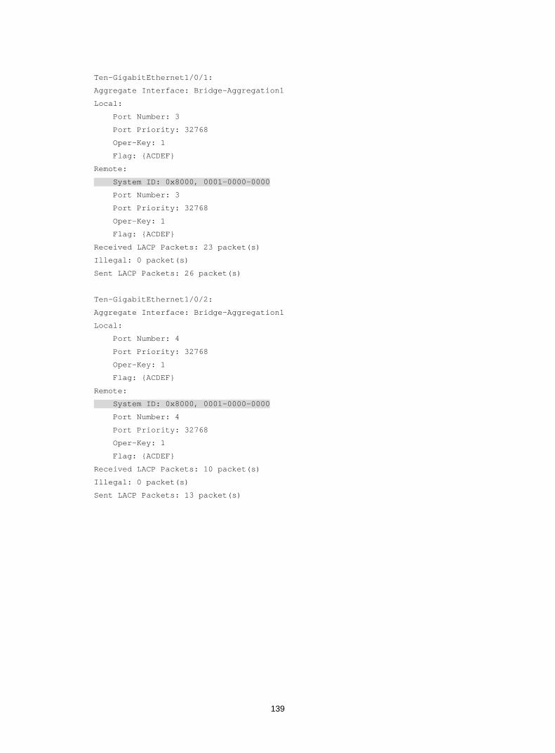
139
Ten-GigabitEthernet1/0/1:
Aggregate Interface: Bridge-Aggregation1
Local:
Port Number: 3
Port Priority: 32768
Oper-Key: 1
Flag: {ACDEF}
Remote:
System ID: 0x8000, 0001-0000-0000
Port Number: 3
Port Priority: 32768
Oper-Key: 1
Flag: {ACDEF}
Received LACP Packets: 23 packet(s)
Illegal: 0 packet(s)
Sent LACP Packets: 26 packet(s)
Ten-GigabitEthernet1/0/2:
Aggregate Interface: Bridge-Aggregation1
Local:
Port Number: 4
Port Priority: 32768
Oper-Key: 1
Flag: {ACDEF}
Remote:
System ID: 0x8000, 0001-0000-0000
Port Number: 4
Port Priority: 32768
Oper-Key: 1
Flag: {ACDEF}
Received LACP Packets: 10 packet(s)
Illegal: 0 packet(s)
Sent LACP Packets: 13 packet(s)
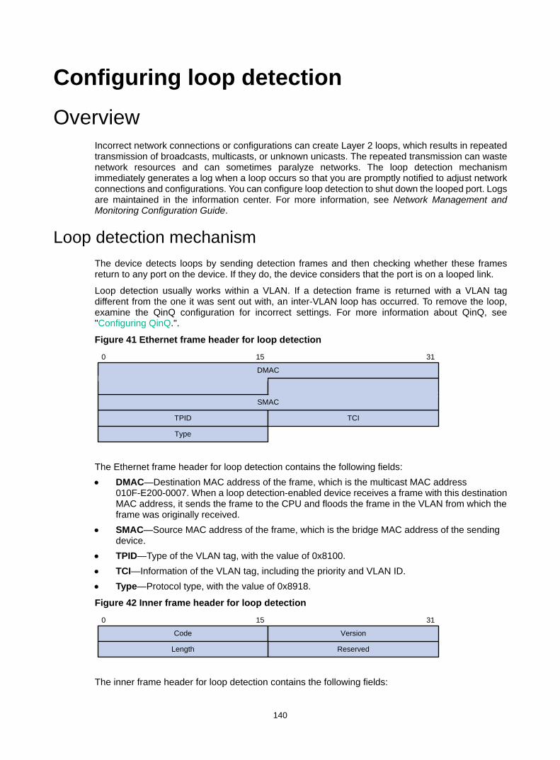
140
Configuring loop detection Overview
Incorrect network connections or configurations can create Layer 2 loops, which results in repeated transmission of broadcasts, multicasts, or unknown unicasts. The repeated transmission can waste network resources and can sometimes paralyze networks. The loop detection mechanism immediately generates a log when a loop occurs so that you are promptly notified to adjust network connections and configurations. You can configure loop detection to shut down the looped port. Logs are maintained in the information center. For more information, see Network Management and Monitoring Configuration Guide.
Loop detection mechanism The device detects loops by sending detection frames and then checking whether these frames return to any port on the device. If they do, the device considers that the port is on a looped link.
Loop detection usually works within a VLAN. If a detection frame is returned with a VLAN tag different from the one it was sent out with, an inter-VLAN loop has occurred. To remove the loop, examine the QinQ configuration for incorrect settings. For more information about QinQ, see "Configuring QinQ.".
Figure 41 Ethernet frame header for loop detection
The Ethernet frame header for loop detection contains the following fields: • DMAC—Destination MAC address of the frame, which is the multicast MAC address
010F-E200-0007. When a loop detection-enabled device receives a frame with this destination MAC address, it sends the frame to the CPU and floods the frame in the VLAN from which the frame was originally received.
• SMAC—Source MAC address of the frame, which is the bridge MAC address of the sending device.
• TPID—Type of the VLAN tag, with the value of 0x8100. • TCI—Information of the VLAN tag, including the priority and VLAN ID. • Type—Protocol type, with the value of 0x8918.
Figure 42 Inner frame header for loop detection
The inner frame header for loop detection contains the following fields:
0 15 31
DMAC
TPID TCI
SMAC
Type
0 15 31
Code
Reserved
Version
Length
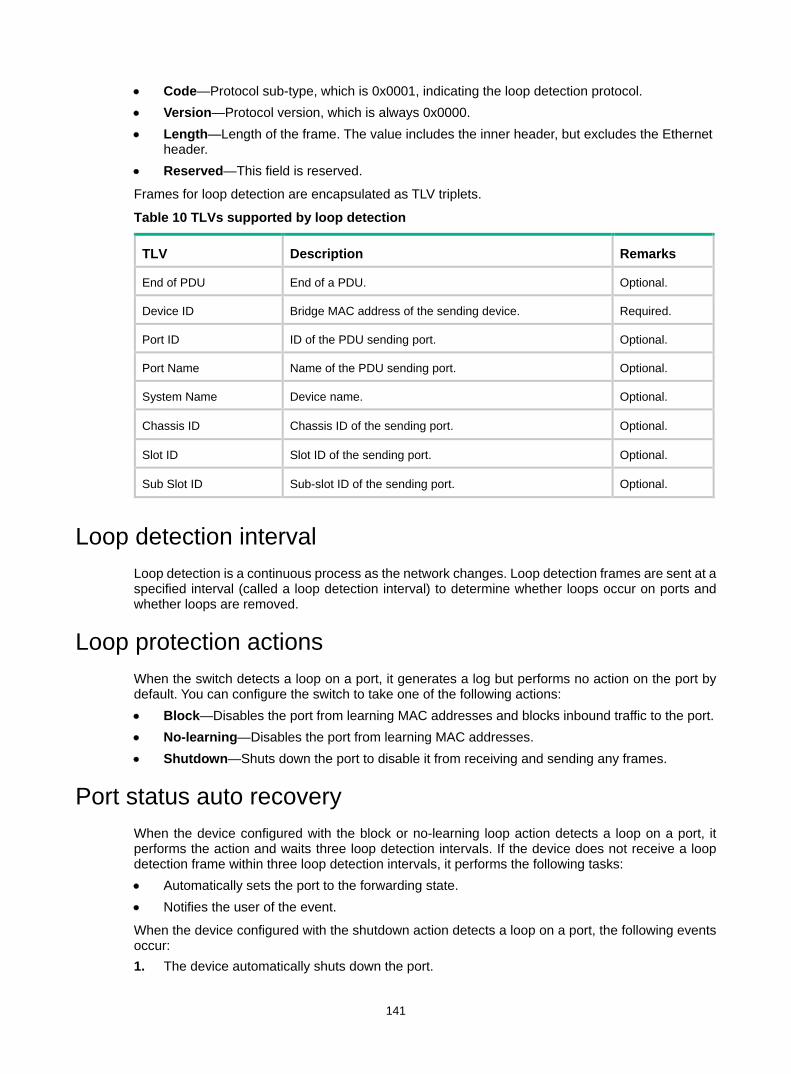
141
• Code—Protocol sub-type, which is 0x0001, indicating the loop detection protocol. • Version—Protocol version, which is always 0x0000. • Length—Length of the frame. The value includes the inner header, but excludes the Ethernet
header. • Reserved—This field is reserved.
Frames for loop detection are encapsulated as TLV triplets.
Table 10 TLVs supported by loop detection
TLV Description Remarks
End of PDU End of a PDU. Optional.
Device ID Bridge MAC address of the sending device. Required.
Port ID ID of the PDU sending port. Optional.
Port Name Name of the PDU sending port. Optional.
System Name Device name. Optional.
Chassis ID Chassis ID of the sending port. Optional.
Slot ID Slot ID of the sending port. Optional.
Sub Slot ID Sub-slot ID of the sending port. Optional.
Loop detection interval Loop detection is a continuous process as the network changes. Loop detection frames are sent at a specified interval (called a loop detection interval) to determine whether loops occur on ports and whether loops are removed.
Loop protection actions When the switch detects a loop on a port, it generates a log but performs no action on the port by default. You can configure the switch to take one of the following actions: • Block—Disables the port from learning MAC addresses and blocks inbound traffic to the port. • No-learning—Disables the port from learning MAC addresses. • Shutdown—Shuts down the port to disable it from receiving and sending any frames.
Port status auto recovery When the device configured with the block or no-learning loop action detects a loop on a port, it performs the action and waits three loop detection intervals. If the device does not receive a loop detection frame within three loop detection intervals, it performs the following tasks: • Automatically sets the port to the forwarding state. • Notifies the user of the event.
When the device configured with the shutdown action detects a loop on a port, the following events occur: 1. The device automatically shuts down the port.
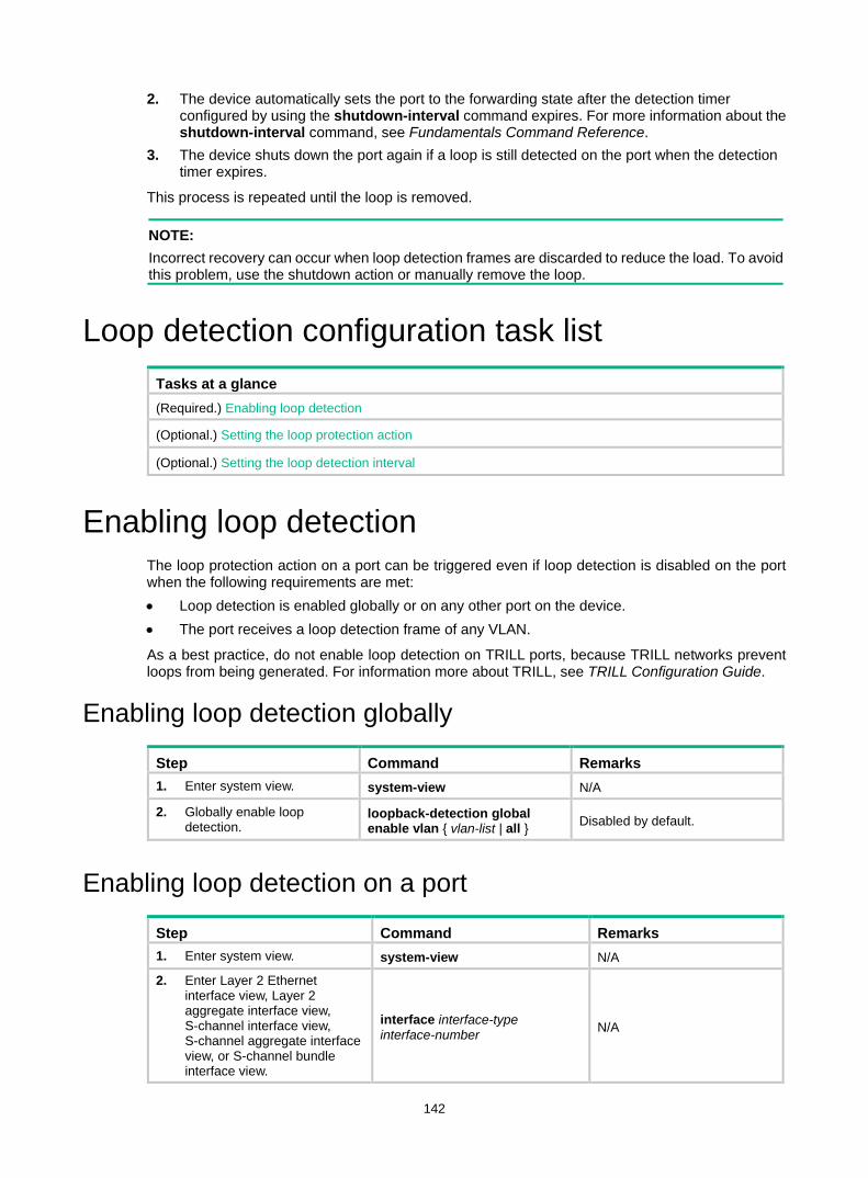
142
2. The device automatically sets the port to the forwarding state after the detection timer configured by using the shutdown-interval command expires. For more information about the shutdown-interval command, see Fundamentals Command Reference.
3. The device shuts down the port again if a loop is still detected on the port when the detection timer expires.
This process is repeated until the loop is removed.
NOTE: Incorrect recovery can occur when loop detection frames are discarded to reduce the load. To avoid this problem, use the shutdown action or manually remove the loop.
Loop detection configuration task list Tasks at a glance (Required.) Enabling loop detection
(Optional.) Setting the loop protection action
(Optional.) Setting the loop detection interval
Enabling loop detection The loop protection action on a port can be triggered even if loop detection is disabled on the port when the following requirements are met: • Loop detection is enabled globally or on any other port on the device. • The port receives a loop detection frame of any VLAN.
As a best practice, do not enable loop detection on TRILL ports, because TRILL networks prevent loops from being generated. For information more about TRILL, see TRILL Configuration Guide.
Enabling loop detection globally
Step Command Remarks 1. Enter system view. system-view N/A
2. Globally enable loop detection.
loopback-detection global enable vlan { vlan-list | all } Disabled by default.
Enabling loop detection on a port
Step Command Remarks 1. Enter system view. system-view N/A
2. Enter Layer 2 Ethernet interface view, Layer 2 aggregate interface view, S-channel interface view, S-channel aggregate interface view, or S-channel bundle interface view.
interface interface-type interface-number N/A
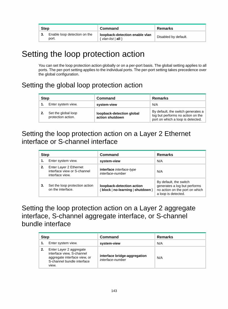
143
Step Command Remarks 3. Enable loop detection on the
port. loopback-detection enable vlan { vlan-list | all } Disabled by default.
Setting the loop protection action You can set the loop protection action globally or on a per-port basis. The global setting applies to all ports. The per-port setting applies to the individual ports. The per-port setting takes precedence over the global configuration.
Setting the global loop protection action
Step Command Remarks 1. Enter system view. system-view N/A
2. Set the global loop protection action.
loopback-detection global action shutdown
By default, the switch generates a log but performs no action on the port on which a loop is detected.
Setting the loop protection action on a Layer 2 Ethernet interface or S-channel interface
Step Command Remarks 1. Enter system view. system-view N/A
2. Enter Layer 2 Ethernet interface view or S-channel interface view.
interface interface-type interface-number N/A
3. Set the loop protection action on the interface.
loopback-detection action { block | no-learning | shutdown }
By default, the switch generates a log but performs no action on the port on which a loop is detected.
Setting the loop protection action on a Layer 2 aggregate interface, S-channel aggregate interface, or S-channel bundle interface
Step Command Remarks 1. Enter system view. system-view N/A
2. Enter Layer 2 aggregate interface view, S-channel aggregate interface view, or S-channel bundle interface view.
interface bridge-aggregation interface-number N/A
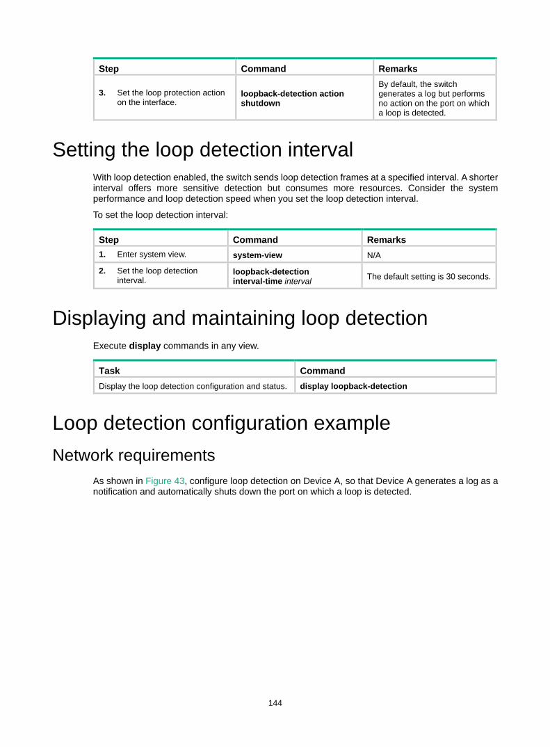
144
Step Command Remarks
3. Set the loop protection action on the interface.
loopback-detection action shutdown
By default, the switch generates a log but performs no action on the port on which a loop is detected.
Setting the loop detection interval With loop detection enabled, the switch sends loop detection frames at a specified interval. A shorter interval offers more sensitive detection but consumes more resources. Consider the system performance and loop detection speed when you set the loop detection interval.
To set the loop detection interval:
Step Command Remarks 1. Enter system view. system-view N/A
2. Set the loop detection interval.
loopback-detection interval-time interval The default setting is 30 seconds.
Displaying and maintaining loop detection Execute display commands in any view.
Task Command Display the loop detection configuration and status. display loopback-detection
Loop detection configuration example Network requirements
As shown in Figure 43, configure loop detection on Device A, so that Device A generates a log as a notification and automatically shuts down the port on which a loop is detected.
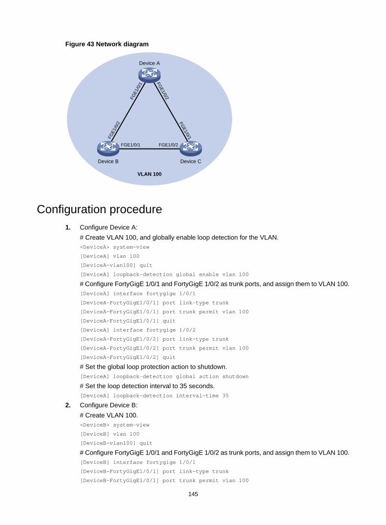
145
Figure 43 Network diagram
Configuration procedure 1. Configure Device A:
# Create VLAN 100, and globally enable loop detection for the VLAN. <DeviceA> system-view
[DeviceA] vlan 100
[DeviceA-vlan100] quit
[DeviceA] loopback-detection global enable vlan 100
# Configure FortyGigE 1/0/1 and FortyGigE 1/0/2 as trunk ports, and assign them to VLAN 100. [DeviceA] interface fortygige 1/0/1
[DeviceA-FortyGigE1/0/1] port link-type trunk
[DeviceA-FortyGigE1/0/1] port trunk permit vlan 100
[DeviceA-FortyGigE1/0/1] quit
[DeviceA] interface fortygige 1/0/2
[DeviceA-FortyGigE1/0/2] port link-type trunk
[DeviceA-FortyGigE1/0/2] port trunk permit vlan 100
[DeviceA-FortyGigE1/0/2] quit
# Set the global loop protection action to shutdown. [DeviceA] loopback-detection global action shutdown
# Set the loop detection interval to 35 seconds. [DeviceA] loopback-detection interval-time 35
2. Configure Device B: # Create VLAN 100. <DeviceB> system-view
[DeviceB] vlan 100
[DeviceB–vlan100] quit
# Configure FortyGigE 1/0/1 and FortyGigE 1/0/2 as trunk ports, and assign them to VLAN 100. [DeviceB] interface fortygige 1/0/1
[DeviceB-FortyGigE1/0/1] port link-type trunk
[DeviceB-FortyGigE1/0/1] port trunk permit vlan 100
FGE1/0/1
Device A
Device B Device C
FGE1/0/2
FGE1
/0/2
FGE1
/0/1
FGE1/0/1
FGE1/0/2
VLAN 100

146
[DeviceB-FortyGigE1/0/1] quit
[DeviceB] interface fortygige 1/0/2
[DeviceB-FortyGigE1/0/2] port link-type trunk
[DeviceB-FortyGigE1/0/2] port trunk permit vlan 100
[DeviceB-FortyGigE1/0/2] quit
3. Configure Device C: # Create VLAN 100. <DeviceC> system-view
[DeviceC] vlan 100
[DeviceC–vlan100] quit
# Configure FortyGigE 1/0/1 and FortyGigE 1/0/2 as trunk ports, and assign them to VLAN 100. [DeviceC] interface fortygige 1/0/1
[DeviceC-FortyGigE1/0/1] port link-type trunk
[DeviceC-FortyGigE1/0/1] port trunk permit vlan 100
[DeviceC-FortyGigE1/0/1] quit
[DeviceC] interface fortygige 1/0/2
[DeviceC-FortyGigE1/0/2] port link-type trunk
[DeviceC-FortyGigE1/0/2] port trunk permit vlan 100
[DeviceC-FortyGigE1/0/2] quit
Verifying the configuration # View the system logs on devices, for example, Device A. [DeviceA]
%Feb 24 15:04:29:663 2013 DeviceA LPDT/4/LPDT_LOOPED: Loopback exists on FortyGigE1/0/1.
%Feb 24 15:04:29:667 2013 DeviceA LPDT/4/LPDT_LOOPED: Loopback exists on FortyGigE1/0/2.
%Feb 24 15:04:44:243 2013 DeviceA LPDT/5/LPDT_RECOVERED: Loopback on FortyGigE1/0/1 recovered.
%Feb 24 15:04:44:248 2013 DeviceA LPDT/5/LPDT_RECOVERED: Loopback on FortyGigE1/0/2 recovered.
The output shows the following information: • Device A detects loops on ports FortyGigE 1/0/1 and FortyGigE 1/0/2 within a loop detection
interval. • Device A automatically shuts down the ports and generates log messages.
# Use the display loopback-detection command to display the loop detection configuration and status on devices, for example, Device A. [DeviceA] display loopback-detection
Loop detection is enabled.
Loop detection interval is 35 second(s).
No loopback is detected.
The output shows that the device has removed the loops from FortyGigE 1/0/1 and FortyGigE 1/0/2 according to the shutdown action.
# Display the status of FortyGigE 1/0/1 on devices, for example, Device A. [DeviceA] display interface fortygige 1/0/1
FortyGigE1/0/1 current state: DOWN (Loop detection down)
...
The output shows that FortyGigE 1/0/1 is already shut down by the loop detection module.

147
# Display the status of FortyGigE 1/0/2 on Device A. [DeviceA] display interface fortygige 1/0/2
FortyGigE1/0/2 current state: DOWN (Loop detection down)
...
The output shows that FortyGigE 1/0/2 is already shut down by the loop detection module.
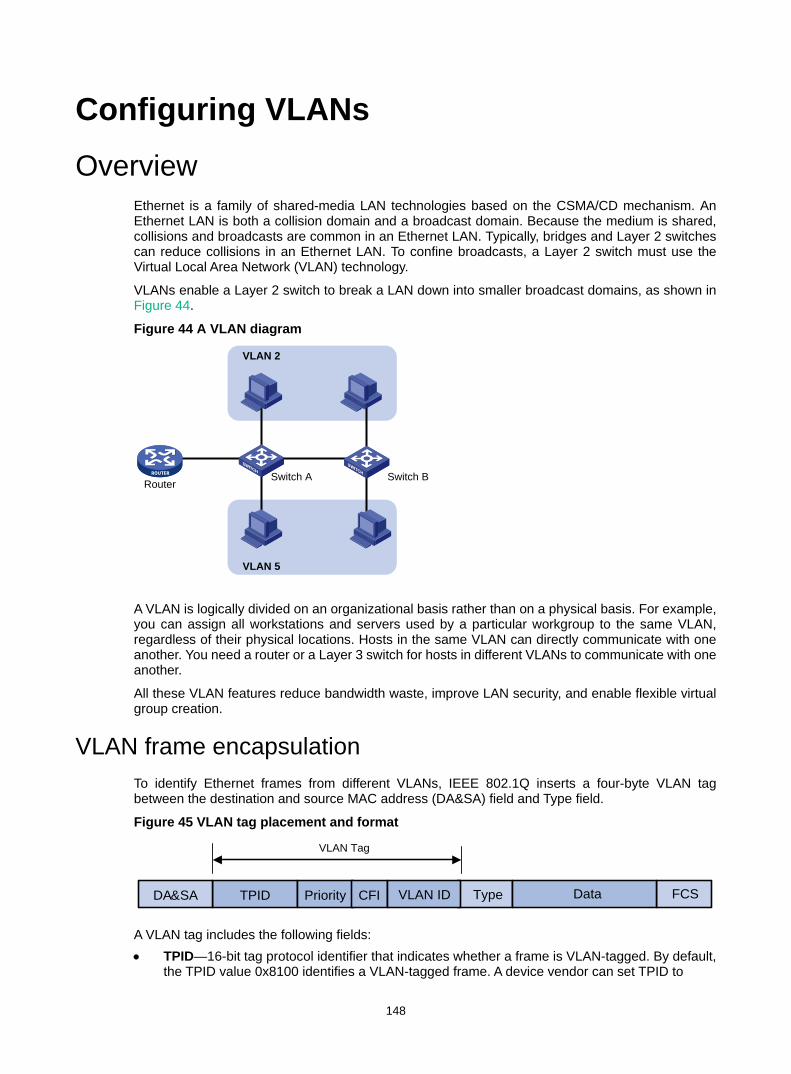
148
Configuring VLANs Overview
Ethernet is a family of shared-media LAN technologies based on the CSMA/CD mechanism. An Ethernet LAN is both a collision domain and a broadcast domain. Because the medium is shared, collisions and broadcasts are common in an Ethernet LAN. Typically, bridges and Layer 2 switches can reduce collisions in an Ethernet LAN. To confine broadcasts, a Layer 2 switch must use the Virtual Local Area Network (VLAN) technology.
VLANs enable a Layer 2 switch to break a LAN down into smaller broadcast domains, as shown in Figure 44.
Figure 44 A VLAN diagram
A VLAN is logically divided on an organizational basis rather than on a physical basis. For example, you can assign all workstations and servers used by a particular workgroup to the same VLAN, regardless of their physical locations. Hosts in the same VLAN can directly communicate with one another. You need a router or a Layer 3 switch for hosts in different VLANs to communicate with one another.
All these VLAN features reduce bandwidth waste, improve LAN security, and enable flexible virtual group creation.
VLAN frame encapsulation To identify Ethernet frames from different VLANs, IEEE 802.1Q inserts a four-byte VLAN tag between the destination and source MAC address (DA&SA) field and Type field.
Figure 45 VLAN tag placement and format
A VLAN tag includes the following fields: • TPID—16-bit tag protocol identifier that indicates whether a frame is VLAN-tagged. By default,
the TPID value 0x8100 identifies a VLAN-tagged frame. A device vendor can set TPID to
VLAN 2
VLAN 5
Switch BSwitch ARouter
TPIDDA&SA TypePriority CFI
VLAN Tag
FCSDataVLAN ID
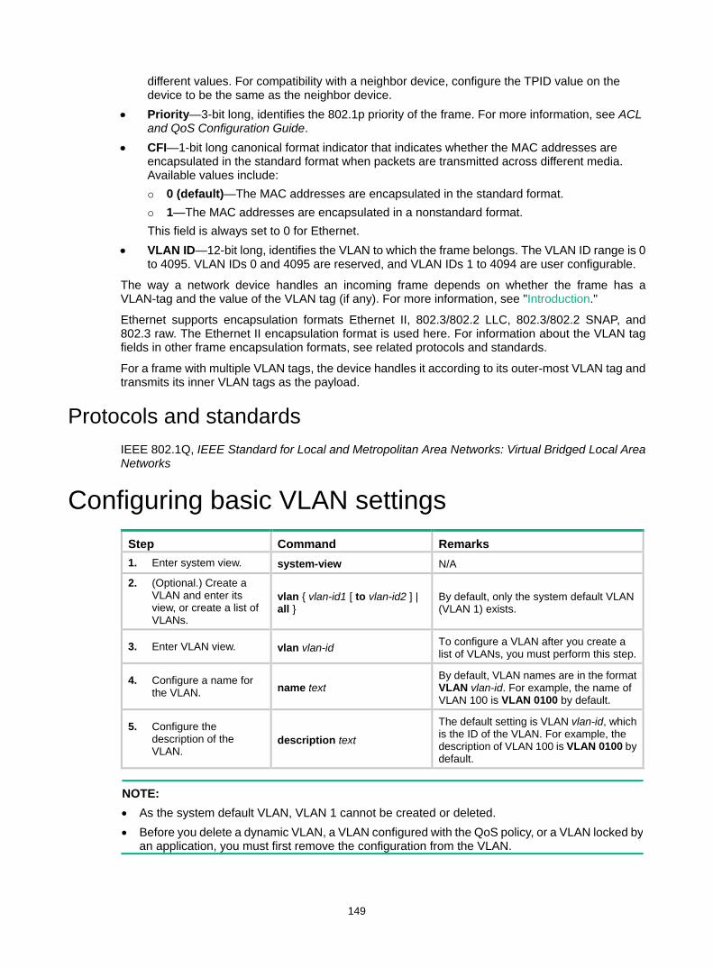
149
different values. For compatibility with a neighbor device, configure the TPID value on the device to be the same as the neighbor device.
• Priority—3-bit long, identifies the 802.1p priority of the frame. For more information, see ACL and QoS Configuration Guide.
• CFI—1-bit long canonical format indicator that indicates whether the MAC addresses are encapsulated in the standard format when packets are transmitted across different media. Available values include: 0 (default)—The MAC addresses are encapsulated in the standard format. 1—The MAC addresses are encapsulated in a nonstandard format. This field is always set to 0 for Ethernet.
• VLAN ID—12-bit long, identifies the VLAN to which the frame belongs. The VLAN ID range is 0 to 4095. VLAN IDs 0 and 4095 are reserved, and VLAN IDs 1 to 4094 are user configurable.
The way a network device handles an incoming frame depends on whether the frame has a VLAN-tag and the value of the VLAN tag (if any). For more information, see "Introduction."
Ethernet supports encapsulation formats Ethernet II, 802.3/802.2 LLC, 802.3/802.2 SNAP, and 802.3 raw. The Ethernet II encapsulation format is used here. For information about the VLAN tag fields in other frame encapsulation formats, see related protocols and standards.
For a frame with multiple VLAN tags, the device handles it according to its outer-most VLAN tag and transmits its inner VLAN tags as the payload.
Protocols and standards IEEE 802.1Q, IEEE Standard for Local and Metropolitan Area Networks: Virtual Bridged Local Area Networks
Configuring basic VLAN settings Step Command Remarks 1. Enter system view. system-view N/A
2. (Optional.) Create a VLAN and enter its view, or create a list of VLANs.
vlan { vlan-id1 [ to vlan-id2 ] | all }
By default, only the system default VLAN (VLAN 1) exists.
3. Enter VLAN view. vlan vlan-id To configure a VLAN after you create a list of VLANs, you must perform this step.
4. Configure a name for the VLAN. name text
By default, VLAN names are in the format VLAN vlan-id. For example, the name of VLAN 100 is VLAN 0100 by default.
5. Configure the description of the VLAN.
description text
The default setting is VLAN vlan-id, which is the ID of the VLAN. For example, the description of VLAN 100 is VLAN 0100 by default.
NOTE: • As the system default VLAN, VLAN 1 cannot be created or deleted. • Before you delete a dynamic VLAN, a VLAN configured with the QoS policy, or a VLAN locked by
an application, you must first remove the configuration from the VLAN.
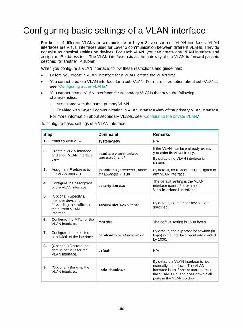
150
Configuring basic settings of a VLAN interface For hosts of different VLANs to communicate at Layer 3, you can use VLAN interfaces. VLAN interfaces are virtual interfaces used for Layer 3 communication between different VLANs. They do not exist as physical entities on devices. For each VLAN, you can create one VLAN interface and assign an IP address to it. The VLAN interface acts as the gateway of the VLAN to forward packets destined for another IP subnet.
When you configure a VLAN interface, follow these restrictions and guidelines: • Before you create a VLAN interface for a VLAN, create the VLAN first. • You cannot create a VLAN interface for a sub-VLAN. For more information about sub-VLANs,
see "Configuring super VLANs." • You cannot create VLAN interfaces for secondary VLANs that have the following
characteristics: Associated with the same primary VLAN. Enabled with Layer 3 communication in VLAN interface view of the primary VLAN interface. For more information about secondary VLANs, see "Configuring the private VLAN."
To configure basic settings of a VLAN interface:
Step Command Remarks 1. Enter system view. system-view N/A
2. Create a VLAN interface and enter VLAN interface view.
interface vlan-interface vlan-interface-id
If the VLAN interface already exists, you enter its view directly. By default, no VLAN interface is created.
3. Assign an IP address to the VLAN interface.
ip address ip-address { mask | mask-length } [ sub ]
By default, no IP address is assigned to any VLAN interface.
4. Configure the description of the VLAN interface. description text
The default setting is the VLAN interface name. For example, Vlan-interface1 Interface.
5. (Optional.) Specify a member device for forwarding the traffic on the current VLAN interface.
service slot slot-number By default, no member devices are specified.
6. Configure the MTU for the VLAN interface. mtu size The default setting is 1500 bytes.
7. Configure the expected bandwidth of the interface. bandwidth bandwidth-value
By default, the expected bandwidth (in kbps) is the interface baud rate divided by 1000.
8. (Optional.) Restore the default settings for the VLAN interface.
default N/A
9. (Optional.) Bring up the VLAN interface. undo shutdown
By default, a VLAN interface is not manually shut down. The VLAN interface is up if one or more ports in the VLAN is up, and goes down if all ports in the VLAN go down.
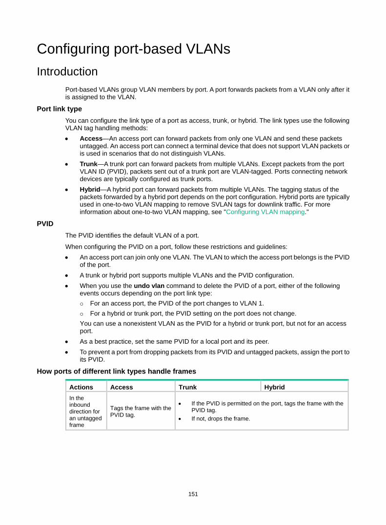
151
Configuring port-based VLANs Introduction
Port-based VLANs group VLAN members by port. A port forwards packets from a VLAN only after it is assigned to the VLAN.
Port link type You can configure the link type of a port as access, trunk, or hybrid. The link types use the following VLAN tag handling methods: • Access—An access port can forward packets from only one VLAN and send these packets
untagged. An access port can connect a terminal device that does not support VLAN packets or is used in scenarios that do not distinguish VLANs.
• Trunk—A trunk port can forward packets from multiple VLANs. Except packets from the port VLAN ID (PVID), packets sent out of a trunk port are VLAN-tagged. Ports connecting network devices are typically configured as trunk ports.
• Hybrid—A hybrid port can forward packets from multiple VLANs. The tagging status of the packets forwarded by a hybrid port depends on the port configuration. Hybrid ports are typically used in one-to-two VLAN mapping to remove SVLAN tags for downlink traffic. For more information about one-to-two VLAN mapping, see "Configuring VLAN mapping."
PVID The PVID identifies the default VLAN of a port.
When configuring the PVID on a port, follow these restrictions and guidelines: • An access port can join only one VLAN. The VLAN to which the access port belongs is the PVID
of the port. • A trunk or hybrid port supports multiple VLANs and the PVID configuration. • When you use the undo vlan command to delete the PVID of a port, either of the following
events occurs depending on the port link type: For an access port, the PVID of the port changes to VLAN 1. For a hybrid or trunk port, the PVID setting on the port does not change. You can use a nonexistent VLAN as the PVID for a hybrid or trunk port, but not for an access port.
• As a best practice, set the same PVID for a local port and its peer. • To prevent a port from dropping packets from its PVID and untagged packets, assign the port to
its PVID.
How ports of different link types handle frames
Actions Access Trunk Hybrid In the inbound direction for an untagged frame
Tags the frame with the PVID tag.
• If the PVID is permitted on the port, tags the frame with the PVID tag.
• If not, drops the frame.
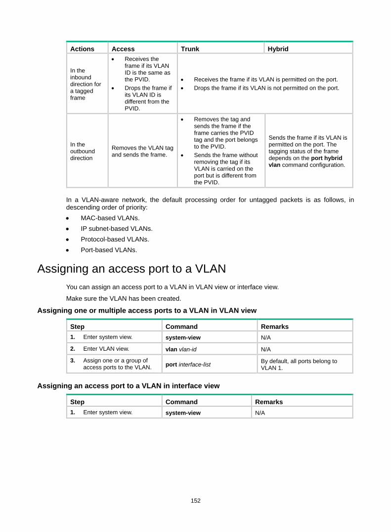
152
Actions Access Trunk Hybrid
In the inbound direction for a tagged frame
• Receives the frame if its VLAN ID is the same as the PVID.
• Drops the frame if its VLAN ID is different from the PVID.
• Receives the frame if its VLAN is permitted on the port. • Drops the frame if its VLAN is not permitted on the port.
In the outbound direction
Removes the VLAN tag and sends the frame.
• Removes the tag and sends the frame if the frame carries the PVID tag and the port belongs to the PVID.
• Sends the frame without removing the tag if its VLAN is carried on the port but is different from the PVID.
Sends the frame if its VLAN is permitted on the port. The tagging status of the frame depends on the port hybrid vlan command configuration.
In a VLAN-aware network, the default processing order for untagged packets is as follows, in descending order of priority: • MAC-based VLANs. • IP subnet-based VLANs. • Protocol-based VLANs. • Port-based VLANs.
Assigning an access port to a VLAN You can assign an access port to a VLAN in VLAN view or interface view.
Make sure the VLAN has been created.
Assigning one or multiple access ports to a VLAN in VLAN view
Step Command Remarks 1. Enter system view. system-view N/A
2. Enter VLAN view. vlan vlan-id N/A
3. Assign one or a group of access ports to the VLAN. port interface-list By default, all ports belong to
VLAN 1.
Assigning an access port to a VLAN in interface view
Step Command Remarks 1. Enter system view. system-view N/A
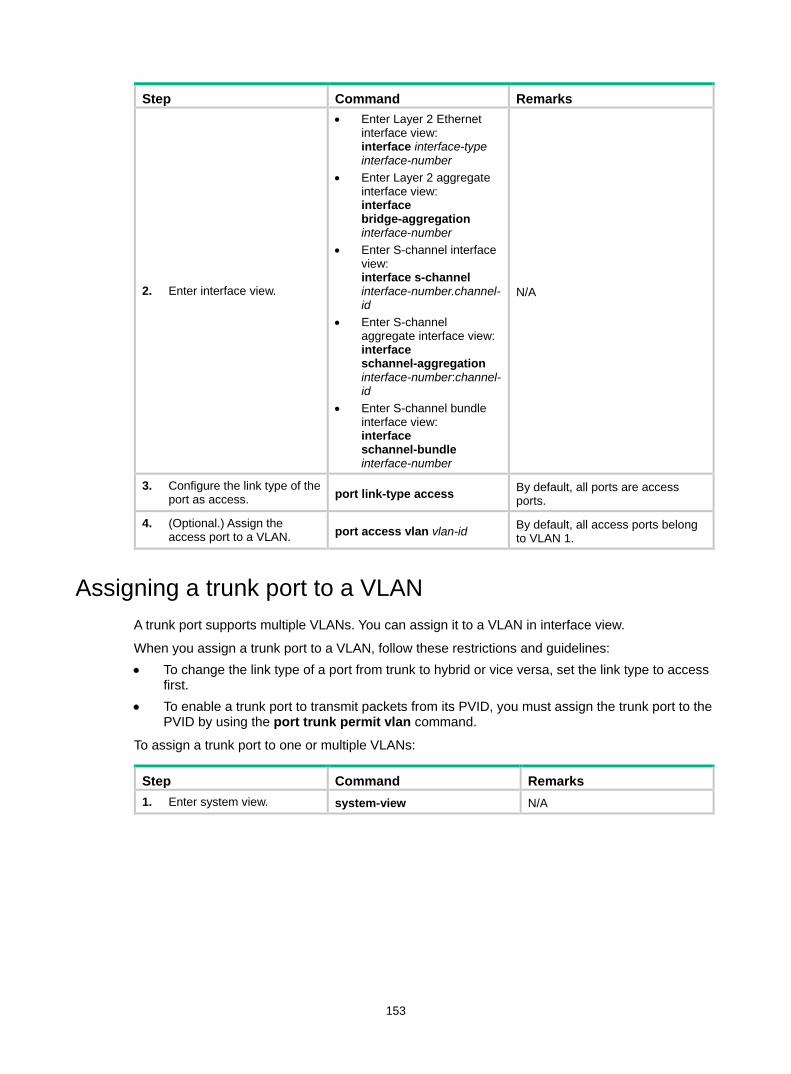
153
Step Command Remarks
2. Enter interface view.
• Enter Layer 2 Ethernet interface view: interface interface-type interface-number
• Enter Layer 2 aggregate interface view: interface bridge-aggregation interface-number
• Enter S-channel interface view: interface s-channel interface-number.channel-id
• Enter S-channel aggregate interface view: interface schannel-aggregation interface-number:channel-id
• Enter S-channel bundle interface view: interface schannel-bundle interface-number
N/A
3. Configure the link type of the port as access. port link-type access By default, all ports are access
ports.
4. (Optional.) Assign the access port to a VLAN. port access vlan vlan-id By default, all access ports belong
to VLAN 1.
Assigning a trunk port to a VLAN A trunk port supports multiple VLANs. You can assign it to a VLAN in interface view.
When you assign a trunk port to a VLAN, follow these restrictions and guidelines: • To change the link type of a port from trunk to hybrid or vice versa, set the link type to access
first. • To enable a trunk port to transmit packets from its PVID, you must assign the trunk port to the
PVID by using the port trunk permit vlan command.
To assign a trunk port to one or multiple VLANs:
Step Command Remarks 1. Enter system view. system-view N/A

154
Step Command Remarks
2. Enter interface view.
• Enter Layer 2 Ethernet interface view: interface interface-type interface-number
• Enter Layer 2 aggregate interface view: interface bridge-aggregation interface-number
• Enter S-channel interface view: interface s-channel interface-number.channel-id
• Enter S-channel aggregate interface view: interface schannel-aggregation interface-number:channel-id
• Enter S-channel bundle interface view: interface schannel-bundle interface-number
N/A
3. Configure the link type of the port as trunk. port link-type trunk By default, all ports are access
ports.
4. Assign the trunk port to the specified VLANs.
port trunk permit vlan { vlan-id-list | all }
By default, a trunk port permits only VLAN 1.
5. (Optional.) Configure the PVID of the trunk port. port trunk pvid vlan vlan-id The default setting is VLAN 1.
Assigning a hybrid port to a VLAN A hybrid port supports multiple VLANs. You can assign it to the specified VLANs in interface view. Make sure the VLANs have been created.
When you assign a hybrid port to a VLAN, follow these restrictions and guidelines: • To change the link type of a port from trunk to hybrid or vice versa, set the link type to access
first. • To enable a hybrid port to transmit packets from its PVID, you must assign the hybrid port to the
PVID by using the port hybrid vlan command.
To assign a hybrid port to one or multiple VLANs:
Step Command Remarks 1. Enter system view. system-view N/A
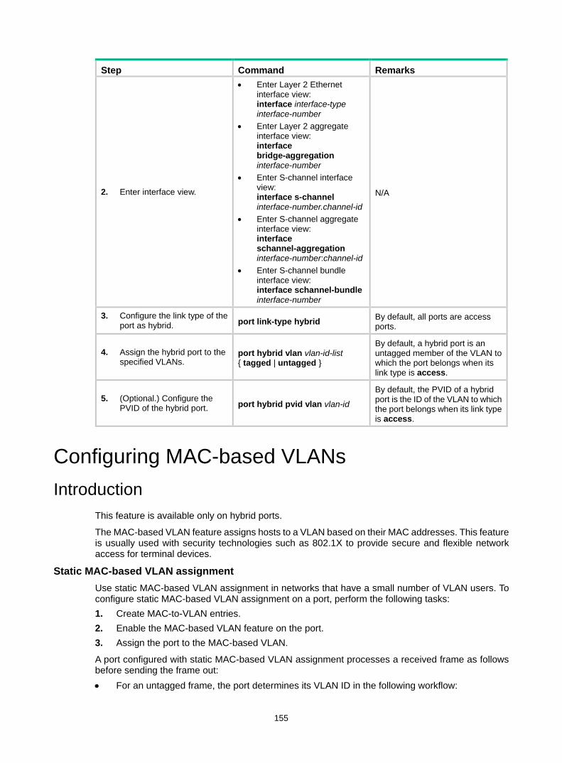
155
Step Command Remarks
2. Enter interface view.
• Enter Layer 2 Ethernet interface view: interface interface-type interface-number
• Enter Layer 2 aggregate interface view: interface bridge-aggregation interface-number
• Enter S-channel interface view: interface s-channel interface-number.channel-id
• Enter S-channel aggregate interface view: interface schannel-aggregation interface-number:channel-id
• Enter S-channel bundle interface view: interface schannel-bundle interface-number
N/A
3. Configure the link type of the port as hybrid. port link-type hybrid By default, all ports are access
ports.
4. Assign the hybrid port to the specified VLANs.
port hybrid vlan vlan-id-list { tagged | untagged }
By default, a hybrid port is an untagged member of the VLAN to which the port belongs when its link type is access.
5. (Optional.) Configure the PVID of the hybrid port. port hybrid pvid vlan vlan-id
By default, the PVID of a hybrid port is the ID of the VLAN to which the port belongs when its link type is access.
Configuring MAC-based VLANs Introduction
This feature is available only on hybrid ports.
The MAC-based VLAN feature assigns hosts to a VLAN based on their MAC addresses. This feature is usually used with security technologies such as 802.1X to provide secure and flexible network access for terminal devices.
Static MAC-based VLAN assignment Use static MAC-based VLAN assignment in networks that have a small number of VLAN users. To configure static MAC-based VLAN assignment on a port, perform the following tasks: 1. Create MAC-to-VLAN entries. 2. Enable the MAC-based VLAN feature on the port. 3. Assign the port to the MAC-based VLAN.
A port configured with static MAC-based VLAN assignment processes a received frame as follows before sending the frame out: • For an untagged frame, the port determines its VLAN ID in the following workflow:
156
a. The port first performs a fuzzy match as follows: − Searches for the MAC-to-VLAN entries whose masks are not all-Fs. − Performs a logical AND operation on the source MAC address and each of these
masks. If the result of an AND operation matches the MAC address in a MAC-to-VLAN entry, the port tags the frame with the VLAN ID specific to this entry.
b. If the fuzzy match fails, the port performs an exact match. It searches for MAC-to-VLAN entries whose masks are all-Fs. If the source MAC address of the frame matches the MAC address of a MAC-to-VLAN entry, the port tags the frame with the VLAN ID specific to this entry.
c. If no matching VLAN ID is found, other criteria, such as IP subnet or protocol, are used for VLAN assignment.
d. If no VLAN is available, the port tags the frame with its PVID. • For a tagged frame, the port determines whether the VLAN ID of the frame is permitted on the
port. If the VLAN ID of the frame is permitted on the port, the port forwards the frame. If the VLAN ID of the frame is not permitted on the port, the port drops the frame.
Dynamic MAC-based VLAN assignment When you cannot determine the target MAC-based VLANs of a port, you can use dynamic MAC-based VLAN assignment on the port. To use dynamic MAC-based VLAN assignment, perform the following tasks: 1. Create MAC-to-VLAN entries. 2. Enable the MAC-based VLAN feature on the port. 3. Enable dynamic MAC-based VLAN assignment on the port.
Dynamic MAC-based VLAN assignment uses the following workflow, as shown in Figure 46: 1. When a port receives a frame, it first determines whether the frame is tagged.
If the frame is tagged, the port reports the source MAC address of the frame. If the frame is untagged, the port selects a VLAN for the frame by using the following
matching order: − MAC-based VLAN. − IP subnet-based VLAN. − Protocol-based VLAN. − Port-based VLAN. After tagging the frame with the selected VLAN, the port reports the source MAC address of the frame.
2. The port uses the source address and VLAN of the frame to match the MAC-to VLAN entries. If the source MAC address of the frame exactly matches the MAC address in a
MAC-to-VLAN entry, the port checks whether the VLAN ID of the frame matches the VLAN in the entry. − If the two VLAN IDs match, the port joins the VLAN and forwards the frame. − If the two VLAN IDs do not match, the port drops the frame.
If the source MAC address of the frame does not match any MAC addresses in MAC-to-VLAN entries exactly, the port checks whether the VLAN ID of the frame is its PVID. − If the VLAN ID of the frame is the PVID of the port, the port determines whether it allows
the PVID. If the PVID is allowed, the port forwards the frame within the PVID. If the PVID is not allowed, the port drops the frame.
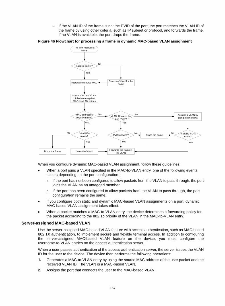
157
− If the VLAN ID of the frame is not the PVID of the port, the port matches the VLAN ID of the frame by using other criteria, such as IP subnet or protocol, and forwards the frame. If no VLAN is available, the port drops the frame.
Figure 46 Flowchart for processing a frame in dynamic MAC-based VLAN assignment
When you configure dynamic MAC-based VLAN assignment, follow these guidelines: • When a port joins a VLAN specified in the MAC-to-VLAN entry, one of the following events
occurs depending on the port configuration: If the port has not been configured to allow packets from the VLAN to pass through, the port
joins the VLAN as an untagged member. If the port has been configured to allow packets from the VLAN to pass through, the port
configuration remains the same. • If you configure both static and dynamic MAC-based VLAN assignments on a port, dynamic
MAC-based VLAN assignment takes effect. • When a packet matches a MAC-to-VLAN entry, the device determines a forwarding policy for
the packet according to the 802.1p priority of the VLAN in the MAC-to-VLAN entry.
Server-assigned MAC-based VLAN Use the server-assigned MAC-based VLAN feature with access authentication, such as MAC-based 802.1X authentication, to implement secure and flexible terminal access. In addition to configuring the server-assigned MAC-based VLAN feature on the device, you must configure the username-to-VLAN entries on the access authentication server.
When a user passes authentication of the access authentication server, the server issues the VLAN ID for the user to the device. The device then performs the following operations: 1. Generates a MAC-to-VLAN entry by using the source MAC address of the user packet and the
received VLAN ID. The VLAN is a MAC-based VLAN. 2. Assigns the port that connects the user to the MAC-based VLAN.
No
Yes
No
Yes
No
No
YesYes
No
Yes
Yes
No
Match MAC and VLAN of the frame against
MAC-to-VLAN entries
MAC addresses exactly match?
VLAN IDsmatch? Drops the frame
Joins the VLAN Forwards the frame in the VLAN
The port receives a frame
Assigns a VLAN by using other criteria
Drops the frame
VLAN ID match the port PVID?
PVID allowed? Available VLAN exists?
Tagged frame ?
Selects a VLAN for the frameReports the source MAC
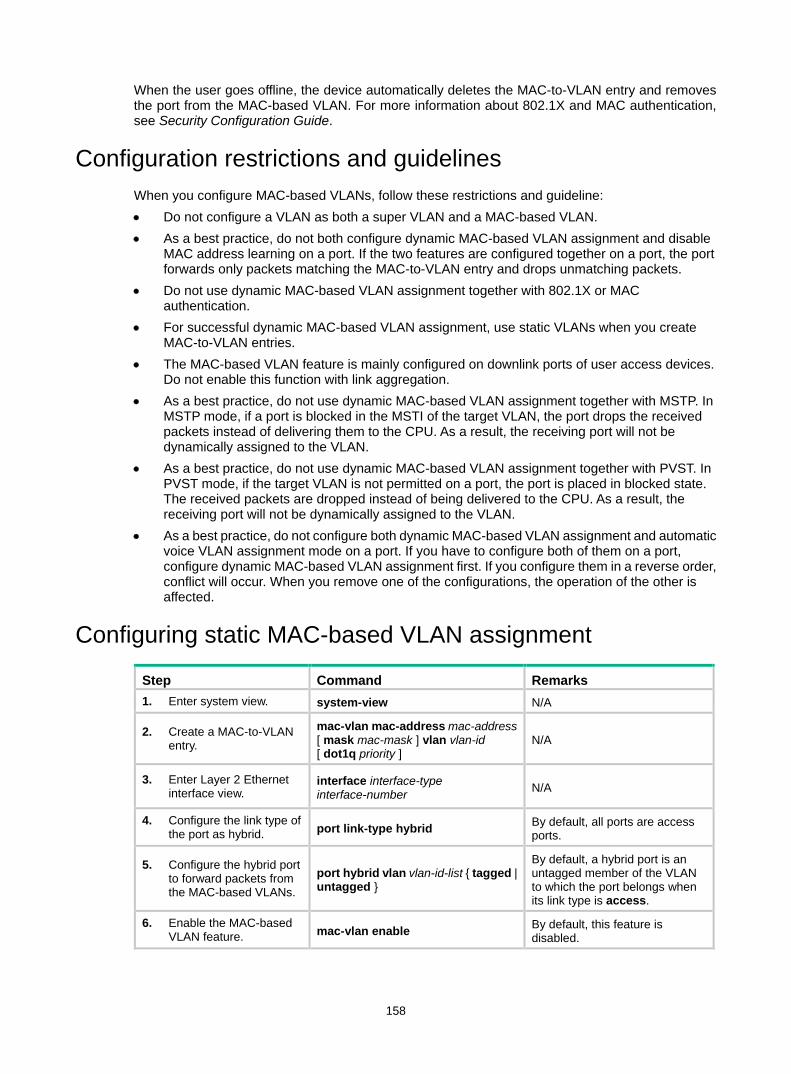
158
When the user goes offline, the device automatically deletes the MAC-to-VLAN entry and removes the port from the MAC-based VLAN. For more information about 802.1X and MAC authentication, see Security Configuration Guide.
Configuration restrictions and guidelines When you configure MAC-based VLANs, follow these restrictions and guideline: • Do not configure a VLAN as both a super VLAN and a MAC-based VLAN. • As a best practice, do not both configure dynamic MAC-based VLAN assignment and disable
MAC address learning on a port. If the two features are configured together on a port, the port forwards only packets matching the MAC-to-VLAN entry and drops unmatching packets.
• Do not use dynamic MAC-based VLAN assignment together with 802.1X or MAC authentication.
• For successful dynamic MAC-based VLAN assignment, use static VLANs when you create MAC-to-VLAN entries.
• The MAC-based VLAN feature is mainly configured on downlink ports of user access devices. Do not enable this function with link aggregation.
• As a best practice, do not use dynamic MAC-based VLAN assignment together with MSTP. In MSTP mode, if a port is blocked in the MSTI of the target VLAN, the port drops the received packets instead of delivering them to the CPU. As a result, the receiving port will not be dynamically assigned to the VLAN.
• As a best practice, do not use dynamic MAC-based VLAN assignment together with PVST. In PVST mode, if the target VLAN is not permitted on a port, the port is placed in blocked state. The received packets are dropped instead of being delivered to the CPU. As a result, the receiving port will not be dynamically assigned to the VLAN.
• As a best practice, do not configure both dynamic MAC-based VLAN assignment and automatic voice VLAN assignment mode on a port. If you have to configure both of them on a port, configure dynamic MAC-based VLAN assignment first. If you configure them in a reverse order, conflict will occur. When you remove one of the configurations, the operation of the other is affected.
Configuring static MAC-based VLAN assignment
Step Command Remarks 1. Enter system view. system-view N/A
2. Create a MAC-to-VLAN entry.
mac-vlan mac-address mac-address [ mask mac-mask ] vlan vlan-id [ dot1q priority ]
N/A
3. Enter Layer 2 Ethernet interface view.
interface interface-type interface-number N/A
4. Configure the link type of the port as hybrid. port link-type hybrid By default, all ports are access
ports.
5. Configure the hybrid port to forward packets from the MAC-based VLANs.
port hybrid vlan vlan-id-list { tagged | untagged }
By default, a hybrid port is an untagged member of the VLAN to which the port belongs when its link type is access.
6. Enable the MAC-based VLAN feature. mac-vlan enable By default, this feature is
disabled.

159
Step Command Remarks
7. (Optional.) Configure VLAN matching order.
vlan precedence { mac-vlan | ip-subnet-vlan }
By default, the system assigns VLANs based on the MAC address preferentially.
Configuring dynamic MAC-based VLAN assignment
Step Command Remarks 1. Enter system view. system-view N/A
2. Create a MAC-to-VLAN entry.
mac-vlan mac-address mac-address vlan vlan-id [ dot1q priority ]
The VLAN assignment for a port is triggered only when the source MAC address of its receiving packet exactly matches the MAC address in the MAC-to-VLAN entry.
3. Enter Layer 2 Ethernet interface view.
interface interface-type interface-number N/A
4. Configure the link type of the port as hybrid. port link-type hybrid By default, all ports are access
ports.
5. Enable the MAC-based VLAN feature. mac-vlan enable By default, MAC-based VLAN is
disabled.
6. Enable dynamic MAC-based VLAN assignment.
mac-vlan trigger enable By default, dynamic MAC-based VLAN assignment is disabled.
7. (Optional.) Configure VLAN matching order.
vlan precedence { mac-vlan | ip-subnet-vlan }
By default, the system assigns VLANs based on the MAC address preferentially.. When you enable dynamic MAC-based VLAN assignment, configure the vlan precedence mac-vlan command to ensure the priority of MAC-based VLAN matching. If you execute the vlan precedence ip-subnet-vlan command, the command will not take effect.
8. (Optional.) Disable the port from forwarding packets that fail the exact MAC address match in its PVID.
port pvid forbidden By default, when a port receives packets whose source MAC addresses fail the exact match, the port forwards them in its PVID.
Configuring server-assigned MAC-based VLAN
Step Command Remarks 1. Enter system view. system-view N/A
2. Enter Layer 2 Ethernet interface view.
interface interface-type interface-number N/A
3. Configure the link type of the ports as hybrid. port link-type hybrid By default, all ports are access
ports.
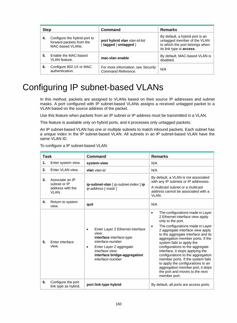
160
Step Command Remarks
4. Configure the hybrid port to forward packets from the MAC-based VLANs.
port hybrid vlan vlan-id-list { tagged | untagged }
By default, a hybrid port is an untagged member of the VLAN to which the port belongs when its link type is access.
5. Enable the MAC-based VLAN feature. mac-vlan enable By default, MAC-based VLAN is
disabled.
6. Configure 802.1X or MAC authentication.
For more information, see Security Command Reference. N/A
Configuring IP subnet-based VLANs In this method, packets are assigned to VLANs based on their source IP addresses and subnet masks. A port configured with IP subnet-based VLANs assigns a received untagged packet to a VLAN based on the source address of the packet.
Use this feature when packets from an IP subnet or IP address must be transmitted in a VLAN.
This feature is available only on hybrid ports, and it processes only untagged packets.
An IP subnet-based VLAN has one or multiple subnets to match inbound packets. Each subnet has a unique index in the IP subnet-based VLAN. All subnets in an IP subnet-based VLAN have the same VLAN ID.
To configure a IP subnet-based VLAN:
Task Command Remarks 1. Enter system view. system-view N/A
2. Enter VLAN view. vlan vlan-id N/A
3. Associate an IP subnet or IP address with the VLAN.
ip-subnet-vlan [ ip-subnet-index ] ip ip-address [ mask ]
By default, a VLAN is not associated with any IP subnets or IP addresses. A multicast subnet or a multicast address cannot be associated with a VLAN.
4. Return to system view. quit N/A
5. Enter interface view.
• Enter Layer 2 Ethernet interface view: interface interface-type interface-number
• Enter Layer 2 aggregate interface view: interface bridge-aggregation interface-number
• The configurations made in Layer 2 Ethernet interface view apply only to the port.
• The configurations made in Layer 2 aggregate interface view apply to the aggregate interface and its aggregation member ports. If the system fails to apply the configurations to the aggregate interface, it stops applying the configurations to the aggregation member ports. If the system fails to apply the configurations to an aggregation member port, it skips the port and moves to the next member port.
6. Configure the port link type as hybrid. port link-type hybrid By default, all ports are access ports.
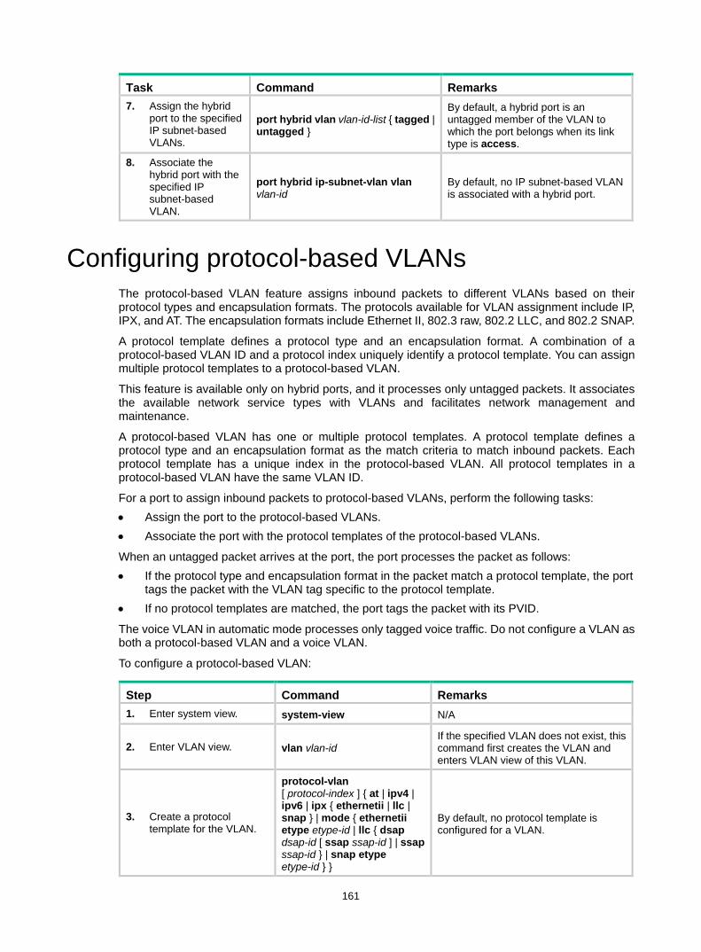
161
Task Command Remarks 7. Assign the hybrid
port to the specified IP subnet-based VLANs.
port hybrid vlan vlan-id-list { tagged | untagged }
By default, a hybrid port is an untagged member of the VLAN to which the port belongs when its link type is access.
8. Associate the hybrid port with the specified IP subnet-based VLAN.
port hybrid ip-subnet-vlan vlan vlan-id
By default, no IP subnet-based VLAN is associated with a hybrid port.
Configuring protocol-based VLANs The protocol-based VLAN feature assigns inbound packets to different VLANs based on their protocol types and encapsulation formats. The protocols available for VLAN assignment include IP, IPX, and AT. The encapsulation formats include Ethernet II, 802.3 raw, 802.2 LLC, and 802.2 SNAP.
A protocol template defines a protocol type and an encapsulation format. A combination of a protocol-based VLAN ID and a protocol index uniquely identify a protocol template. You can assign multiple protocol templates to a protocol-based VLAN.
This feature is available only on hybrid ports, and it processes only untagged packets. It associates the available network service types with VLANs and facilitates network management and maintenance.
A protocol-based VLAN has one or multiple protocol templates. A protocol template defines a protocol type and an encapsulation format as the match criteria to match inbound packets. Each protocol template has a unique index in the protocol-based VLAN. All protocol templates in a protocol-based VLAN have the same VLAN ID.
For a port to assign inbound packets to protocol-based VLANs, perform the following tasks: • Assign the port to the protocol-based VLANs. • Associate the port with the protocol templates of the protocol-based VLANs.
When an untagged packet arrives at the port, the port processes the packet as follows: • If the protocol type and encapsulation format in the packet match a protocol template, the port
tags the packet with the VLAN tag specific to the protocol template. • If no protocol templates are matched, the port tags the packet with its PVID.
The voice VLAN in automatic mode processes only tagged voice traffic. Do not configure a VLAN as both a protocol-based VLAN and a voice VLAN.
To configure a protocol-based VLAN:
Step Command Remarks 1. Enter system view. system-view N/A
2. Enter VLAN view. vlan vlan-id If the specified VLAN does not exist, this command first creates the VLAN and enters VLAN view of this VLAN.
3. Create a protocol template for the VLAN.
protocol-vlan [ protocol-index ] { at | ipv4 | ipv6 | ipx { ethernetii | llc | snap } | mode { ethernetii etype etype-id | llc { dsap dsap-id [ ssap ssap-id ] | ssap ssap-id } | snap etype etype-id } }
By default, no protocol template is configured for a VLAN.
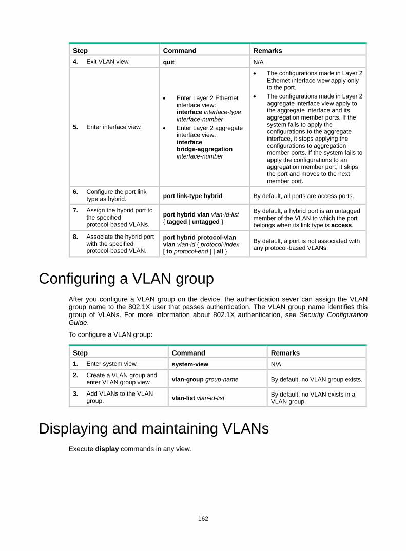
162
Step Command Remarks 4. Exit VLAN view. quit N/A
5. Enter interface view.
• Enter Layer 2 Ethernet interface view: interface interface-type interface-number
• Enter Layer 2 aggregate interface view: interface bridge-aggregation interface-number
• The configurations made in Layer 2 Ethernet interface view apply only to the port.
• The configurations made in Layer 2 aggregate interface view apply to the aggregate interface and its aggregation member ports. If the system fails to apply the configurations to the aggregate interface, it stops applying the configurations to aggregation member ports. If the system fails to apply the configurations to an aggregation member port, it skips the port and moves to the next member port.
6. Configure the port link type as hybrid. port link-type hybrid By default, all ports are access ports.
7. Assign the hybrid port to the specified protocol-based VLANs. port hybrid vlan vlan-id-list
{ tagged | untagged }
By default, a hybrid port is an untagged member of the VLAN to which the port belongs when its link type is access.
8. Associate the hybrid port with the specified protocol-based VLAN.
port hybrid protocol-vlan vlan vlan-id { protocol-index [ to protocol-end ] | all }
By default, a port is not associated with any protocol-based VLANs.
Configuring a VLAN group After you configure a VLAN group on the device, the authentication sever can assign the VLAN group name to the 802.1X user that passes authentication. The VLAN group name identifies this group of VLANs. For more information about 802.1X authentication, see Security Configuration Guide.
To configure a VLAN group:
Step Command Remarks 1. Enter system view. system-view N/A
2. Create a VLAN group and enter VLAN group view. vlan-group group-name By default, no VLAN group exists.
3. Add VLANs to the VLAN group. vlan-list vlan-id-list By default, no VLAN exists in a
VLAN group.
Displaying and maintaining VLANs Execute display commands in any view.
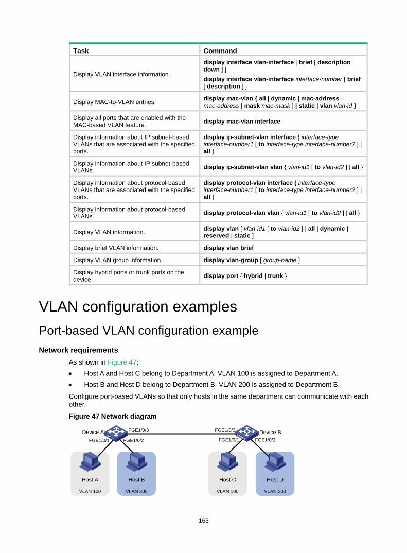
163
Task Command
Display VLAN interface information.
display interface vlan-interface [ brief [ description | down ] ] display interface vlan-interface interface-number [ brief [ description ] ]
Display MAC-to-VLAN entries. display mac-vlan { all | dynamic | mac-address mac-address [ mask mac-mask ] | static | vlan vlan-id }
Display all ports that are enabled with the MAC-based VLAN feature. display mac-vlan interface
Display information about IP subnet-based VLANs that are associated with the specified ports.
display ip-subnet-vlan interface { interface-type interface-number1 [ to interface-type interface-number2 ] | all }
Display information about IP subnet-based VLANs. display ip-subnet-vlan vlan { vlan-id1 [ to vlan-id2 ] | all }
Display information about protocol-based VLANs that are associated with the specified ports.
display protocol-vlan interface { interface-type interface-number1 [ to interface-type interface-number2 ] | all }
Display information about protocol-based VLANs. display protocol-vlan vlan { vlan-id1 [ to vlan-id2 ] | all }
Display VLAN information. display vlan [ vlan-id1 [ to vlan-id2 ] | all | dynamic | reserved | static ]
Display brief VLAN information. display vlan brief
Display VLAN group information. display vlan-group [ group-name ]
Display hybrid ports or trunk ports on the device. display port { hybrid | trunk }
VLAN configuration examples Port-based VLAN configuration example Network requirements
As shown in Figure 47: • Host A and Host C belong to Department A. VLAN 100 is assigned to Department A. • Host B and Host D belong to Department B. VLAN 200 is assigned to Department B.
Configure port-based VLANs so that only hosts in the same department can communicate with each other.
Figure 47 Network diagram
FGE1/0/2FGE1/0/1
Host A Host CHost B Host D
Device A
VLAN 100 VLAN 100VLAN 200 VLAN 200
Device BFGE1/0/1 FGE1/0/2
FGE1/0/3 FGE1/0/3
164
Configuration procedure 1. Configure Device A:
# Create VLAN 100, and assign FortyGigE 1/0/1 to VLAN 100. <DeviceA> system-view
[DeviceA] vlan 100
[DeviceA-vlan100] port fortygige 1/0/1
[DeviceA-vlan100] quit
# Create VLAN 200, and assign FortyGigE 1/0/2 to VLAN 200. [DeviceA] vlan 200
[DeviceA-vlan200] port fortygige 1/0/2
[DeviceA-vlan200] quit
# Configure FortyGigE 1/0/3 as a trunk port to forward packets from VLANs 100 and 200 to Device B. [DeviceA] interface fortygige 1/0/3
[DeviceA-FortyGigE1/0/3] port link-type trunk
[DeviceA-FortyGigE1/0/3] port trunk permit vlan 100 200
Please wait... Done.
2. Configure Device B in the same way Device A is configured. (Details not shown.) 3. Configure hosts:
Configure Host A and Host C to be on the same IP subnet. For example, 192.168.100.0/24. Configure Host B and Host D to be on the same IP subnet. For example, 192.168.200.0/24.
Verifying the configuration # Verify that Host A and Host C can ping each other, but they both fail to ping Host B. (Details not shown.)
# Verify that Host B and Host D can ping each other, but they both fail to ping Host A. (Details not shown.)
# Verify that VLANs 100 and 200 are correctly configured on devices, for example, on Device A. [DeviceA-FortyGigE1/0/3] display vlan 100
VLAN ID: 100
VLAN type: Static
Route interface: Not configured
Description: VLAN 0100
Name: VLAN 0100
Tagged ports:
FortyGigE1/0/3
Untagged ports:
FortyGigE1/0/1
[DeviceA-FortyGigE1/0/3] display vlan 200
VLAN ID: 200
VLAN type: Static
Route interface: Not configured
Description: VLAN 0200
Name: VLAN 0200
Tagged ports:
FortyGigE1/0/3
Untagged ports:
FortyGigE1/0/2
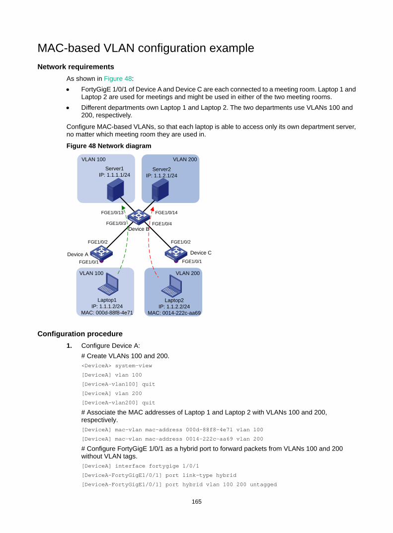
165
MAC-based VLAN configuration example Network requirements
As shown in Figure 48: • FortyGigE 1/0/1 of Device A and Device C are each connected to a meeting room. Laptop 1 and
Laptop 2 are used for meetings and might be used in either of the two meeting rooms. • Different departments own Laptop 1 and Laptop 2. The two departments use VLANs 100 and
200, respectively.
Configure MAC-based VLANs, so that each laptop is able to access only its own department server, no matter which meeting room they are used in.
Figure 48 Network diagram
Configuration procedure 1. Configure Device A:
# Create VLANs 100 and 200. <DeviceA> system-view
[DeviceA] vlan 100
[DeviceA-vlan100] quit
[DeviceA] vlan 200
[DeviceA-vlan200] quit
# Associate the MAC addresses of Laptop 1 and Laptop 2 with VLANs 100 and 200, respectively. [DeviceA] mac-vlan mac-address 000d-88f8-4e71 vlan 100
[DeviceA] mac-vlan mac-address 0014-222c-aa69 vlan 200
# Configure FortyGigE 1/0/1 as a hybrid port to forward packets from VLANs 100 and 200 without VLAN tags. [DeviceA] interface fortygige 1/0/1
[DeviceA-FortyGigE1/0/1] port link-type hybrid
[DeviceA-FortyGigE1/0/1] port hybrid vlan 100 200 untagged
Device A Device C
Device B
Server1IP: 1.1.1.1/24
Server2 IP: 1.1.2.1/24
FGE1/0/1 FGE1/0/1
Laptop1IP: 1.1.1.2/24
MAC: 000d-88f8-4e71
Laptop2 IP: 1.1.2.2/24
MAC: 0014-222c-aa69
VLAN 100 VLAN 200
FGE1/0/2 FGE1/0/2
FGE1/0/3 FGE1/0/4
FGE1/0/14FGE1/0/13
VLAN 100 VLAN 200

166
# Enable the MAC-based VLAN feature on FortyGigE 1/0/1. [DeviceA-FortyGigE1/0/1] mac-vlan enable
[DeviceA-FortyGigE1/0/1] quit
# Configure the uplink port FortyGigE 1/0/2 as a trunk port, and assign it to VLANs 100 and 200. [DeviceA] interface fortygige 1/0/2
[DeviceA-FortyGigE1/0/2] port link-type trunk
[DeviceA-FortyGigE1/0/2] port trunk permit vlan 100 200
[DeviceA-FortyGigE1/0/2] quit
2. Configure Device B: # Create VLAN 100 and assign FortyGigE 1/0/13 to VLAN 100. <DeviceB> system-view
[DeviceB] vlan 100
[DeviceB-vlan100] port fortygige 1/0/13
[DeviceB-vlan100] quit
# Create VLAN 200 and assign FortyGigE 1/0/14 to VLAN 200. [DeviceB] vlan 200
[DeviceB-vlan200] port fortygige 1/0/14
[DeviceB-vlan200] quit
# Configure FortyGigE 1/0/3 as a trunk port, and assign the port to VLANs 100 and 200. [DeviceB] interface fortygige 1/0/3
[DeviceB-FortyGigE1/0/3] port link-type trunk
[DeviceB-FortyGigE1/0/3] port trunk permit vlan 100 200
[DeviceB-FortyGigE1/0/3] quit
# Configure FortyGigE 1/0/4 as a trunk port, and assign the port to VLANs 100 and 200. [DeviceB] interface fortygige 1/0/4
[DeviceB-FortyGigE1/0/4] port link-type trunk
[DeviceB-FortyGigE1/0/4] port trunk permit vlan 100 200
[DeviceB-FortyGigE1/0/4] quit
3. Configure Device C in the same way as the Device A is configured. (Details not shown.)
Verifying the configuration # Verify that Laptop 1 can access only Server 1, and Laptop 2 can access only Server 2. (Details not shown.)
# Verify the MAC-to-VLAN entries on Device A and Device C, for example, Device A. [DeviceA] display mac-vlan all
The following MAC VLAN addresses exist:
S:Static D:Dynamic
MAC address Mask VLAN ID Dot1q State
000d-88f8-4e71 ffff-ffff-ffff 100 0 S
0014-222c-aa69 ffff-ffff-ffff 200 0 S
Total MAC VLAN address count: 2
IP subnet-based VLAN configuration example Network requirements
As shown in Figure 49, the hosts in the office belong to different IP subnets.
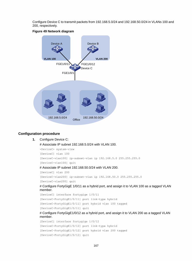
167
Configure Device C to transmit packets from 192.168.5.0/24 and 192.168.50.0/24 in VLANs 100 and 200, respectively.
Figure 49 Network diagram
Configuration procedure 1. Configure Device C:
# Associate IP subnet 192.168.5.0/24 with VLAN 100. <DeviceC> system-view
[DeviceC] vlan 100
[DeviceC-vlan100] ip-subnet-vlan ip 192.168.5.0 255.255.255.0
[DeviceC-vlan100] quit
# Associate IP subnet 192.168.50.0/24 with VLAN 200. [DeviceC] vlan 200
[DeviceC-vlan200] ip-subnet-vlan ip 192.168.50.0 255.255.255.0
[DeviceC-vlan200] quit
# Configure FortyGigE 1/0/11 as a hybrid port, and assign it to VLAN 100 as a tagged VLAN member. [DeviceC] interface fortygige 1/0/11
[DeviceC-FortyGigE1/0/11] port link-type hybrid
[DeviceC-FortyGigE1/0/11] port hybrid vlan 100 tagged
[DeviceC-FortyGigE1/0/11] quit
# Configure FortyGigE1/0/12 as a hybrid port, and assign it to VLAN 200 as a tagged VLAN member. [DeviceC] interface fortygige 1/0/12
[DeviceC-FortyGigE1/0/12] port link-type hybrid
[DeviceC-FortyGigE1/0/12] port hybrid vlan 200 tagged
[DeviceC-FortyGigE1/0/12] quit
Device A Device B
Office
Device C
VLAN 100 VLAN 200
192.168.5.0/24 192.168.50.0/24
FGE1/0/11 FGE1/0/12
FGE1/0/1
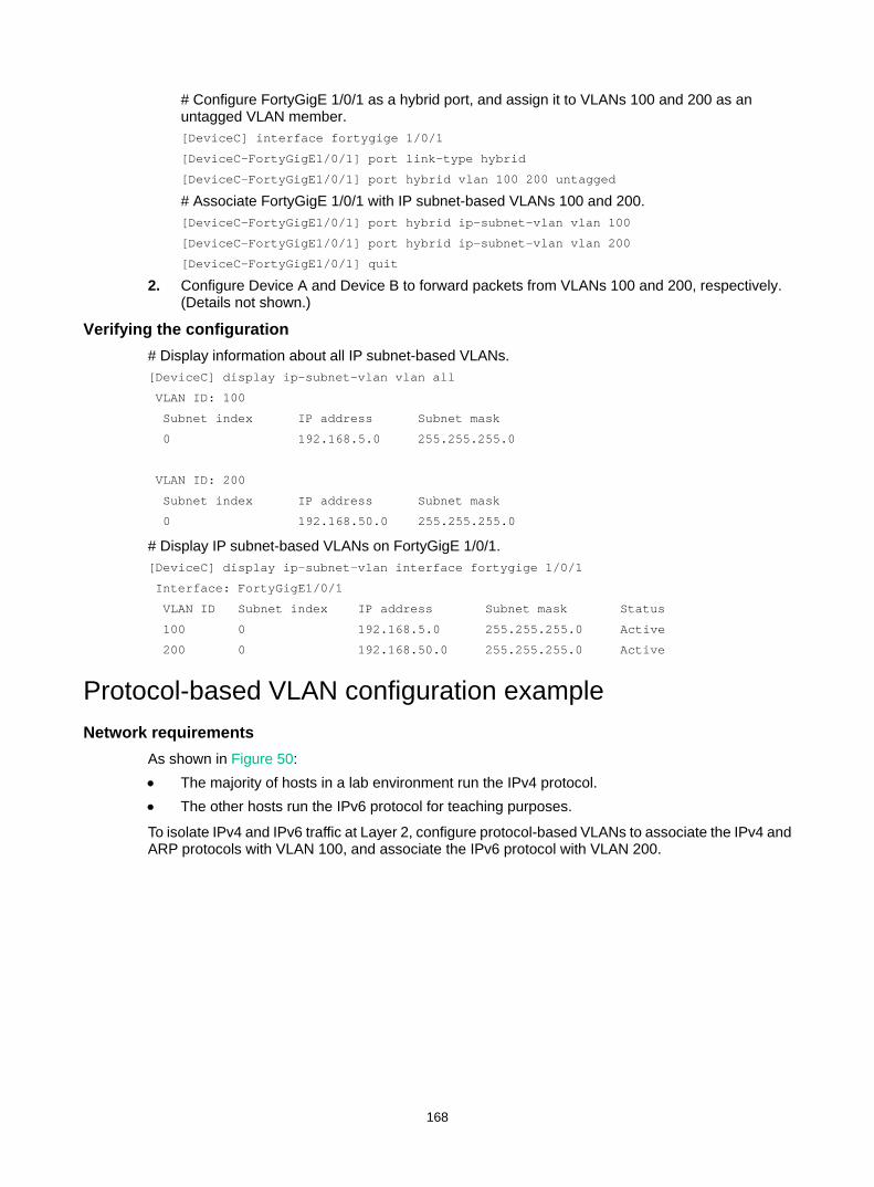
168
# Configure FortyGigE 1/0/1 as a hybrid port, and assign it to VLANs 100 and 200 as an untagged VLAN member. [DeviceC] interface fortygige 1/0/1
[DeviceC-FortyGigE1/0/1] port link-type hybrid
[DeviceC-FortyGigE1/0/1] port hybrid vlan 100 200 untagged
# Associate FortyGigE 1/0/1 with IP subnet-based VLANs 100 and 200. [DeviceC-FortyGigE1/0/1] port hybrid ip-subnet-vlan vlan 100
[DeviceC-FortyGigE1/0/1] port hybrid ip-subnet-vlan vlan 200
[DeviceC-FortyGigE1/0/1] quit
2. Configure Device A and Device B to forward packets from VLANs 100 and 200, respectively. (Details not shown.)
Verifying the configuration # Display information about all IP subnet-based VLANs. [DeviceC] display ip-subnet-vlan vlan all
VLAN ID: 100
Subnet index IP address Subnet mask
0 192.168.5.0 255.255.255.0
VLAN ID: 200
Subnet index IP address Subnet mask
0 192.168.50.0 255.255.255.0
# Display IP subnet-based VLANs on FortyGigE 1/0/1. [DeviceC] display ip-subnet-vlan interface fortygige 1/0/1
Interface: FortyGigE1/0/1
VLAN ID Subnet index IP address Subnet mask Status
100 0 192.168.5.0 255.255.255.0 Active
200 0 192.168.50.0 255.255.255.0 Active
Protocol-based VLAN configuration example Network requirements
As shown in Figure 50: • The majority of hosts in a lab environment run the IPv4 protocol. • The other hosts run the IPv6 protocol for teaching purposes.
To isolate IPv4 and IPv6 traffic at Layer 2, configure protocol-based VLANs to associate the IPv4 and ARP protocols with VLAN 100, and associate the IPv6 protocol with VLAN 200.
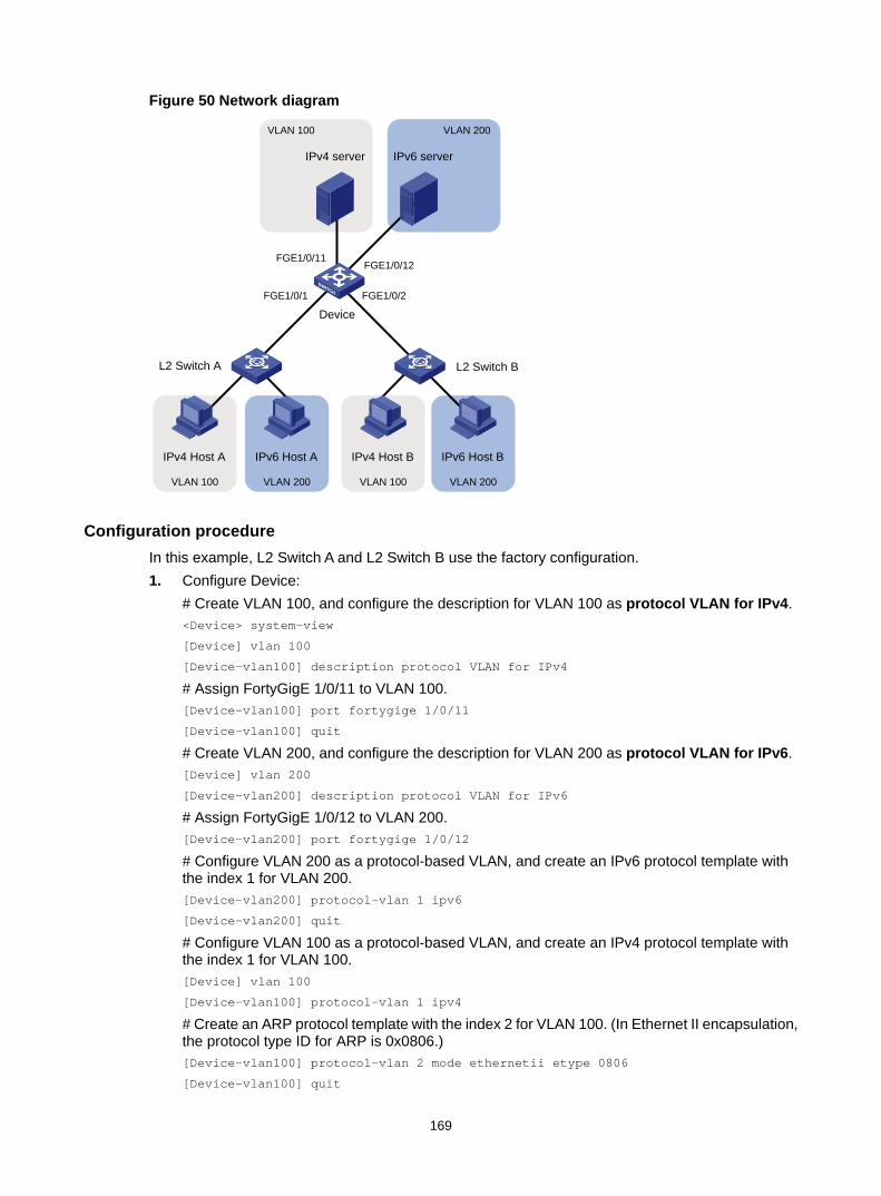
169
Figure 50 Network diagram
Configuration procedure In this example, L2 Switch A and L2 Switch B use the factory configuration. 1. Configure Device:
# Create VLAN 100, and configure the description for VLAN 100 as protocol VLAN for IPv4. <Device> system-view
[Device] vlan 100
[Device-vlan100] description protocol VLAN for IPv4
# Assign FortyGigE 1/0/11 to VLAN 100. [Device-vlan100] port fortygige 1/0/11
[Device-vlan100] quit
# Create VLAN 200, and configure the description for VLAN 200 as protocol VLAN for IPv6. [Device] vlan 200
[Device-vlan200] description protocol VLAN for IPv6
# Assign FortyGigE 1/0/12 to VLAN 200. [Device-vlan200] port fortygige 1/0/12
# Configure VLAN 200 as a protocol-based VLAN, and create an IPv6 protocol template with the index 1 for VLAN 200. [Device-vlan200] protocol-vlan 1 ipv6
[Device-vlan200] quit
# Configure VLAN 100 as a protocol-based VLAN, and create an IPv4 protocol template with the index 1 for VLAN 100. [Device] vlan 100
[Device-vlan100] protocol-vlan 1 ipv4
# Create an ARP protocol template with the index 2 for VLAN 100. (In Ethernet II encapsulation, the protocol type ID for ARP is 0x0806.) [Device-vlan100] protocol-vlan 2 mode ethernetii etype 0806
[Device-vlan100] quit
FGE1/0/2FGE1/0/1
FGE1/0/11FGE1/0/12
IPv4 Host A IPv4 Host BIPv6 Host A IPv6 Host B
IPv4 server IPv6 server
Device
L2 Switch A L2 Switch B
VLAN 100 VLAN 100
VLAN 100
VLAN 200 VLAN 200
VLAN 200

170
# Configure FortyGigE 1/0/1 as a hybrid port, and assign it to VLANs 100 and 200 as an untagged VLAN member. [Device] interface fortygige 1/0/1
[Device-FortyGigE1/0/1] port link-type hybrid
[Device-FortyGigE1/0/1] port hybrid vlan 100 200 untagged
# Associate FortyGigE 1/0/1 with the IPv4 and ARP protocol templates of VLAN 100 and the IPv6 protocol template of VLAN 200. [Device-FortyGigE1/0/1] port hybrid protocol-vlan vlan 100 1 to 2
[Device-FortyGigE1/0/1] port hybrid protocol-vlan vlan 200 1
[Device-FortyGigE1/0/1] quit
# Configure FortyGigE 1/0/2 as a hybrid port, and assign it to VLANs 100 and 200 as an untagged VLAN member. [Device] interface fortygige 1/0/2
[Device-FortyGigE1/0/2] port link-type hybrid
[Device-FortyGigE1/0/2] port hybrid vlan 100 200 untagged
# Associate FortyGigE 1/0/2 with the IPv4 and ARP protocol templates of VLAN 100 and the IPv6 protocol template of VLAN 200. [Device-FortyGigE1/0/2] port hybrid protocol-vlan vlan 100 1 to 2
[Device-FortyGigE1/0/2] port hybrid protocol-vlan vlan 200 1
[Device-FortyGigE1/0/2] quit
2. Configure hosts and servers: a. Configure IPv4 Host A, IPv4 Host B, and IPv4 server to be on the same network segment
(192.168.100.0/24, for example). (Details not shown.) b. Configure IPv6 Host A, IPv6 Host B, and IPv6 server to be on the same network segment
(2001::1/64, for example). (Details not shown.)
Verifying the configuration 1. Verify the following:
The hosts and the server in VLAN 100 can successfully ping one another. (Details not shown.)
The hosts and the server in VLAN 200 can successfully ping one another. (Details not shown.)
The hosts or the server in VLAN 100 cannot ping the hosts or server in VLAN 200. (Details not shown.)
2. Verify the protocol-based VLAN configuration: # Display protocol-based VLANs on Device. [Device] display protocol-vlan vlan all
VLAN ID: 100
Protocol index Protocol type
1 IPv4
2 Ethernet II Etype 0x0806
VLAN ID: 200
Protocol index Protocol type
1 IPv6
# Display protocol-based VLANs on the ports of Device. [Device] display protocol-vlan interface all
Interface: FortyGigE1/0/1
VLAN ID Protocol index Protocol type Status

171
100 1 IPv4 Active
100 2 Ethernet II Etype 0x0806 Active
200 1 IPv6 Active
Interface: FortyGigE 1/0/2
VLAN ID Protocol index Protocol type Status
100 1 IPv4 Active
100 2 Ethernet II Etype 0x0806 Active
200 1 IPv6 Active
172
Configuring super VLANs Hosts in a VLAN typically use IP addresses in the same subnet. For Layer 3 interoperability with other VLANs, you can create a VLAN interface for the VLAN and assign an IP address to it. This requires a large number of IP addresses.
The super VLAN feature was introduced to save IP addresses. A super VLAN is associated with multiple sub-VLANs. These sub-VLANs use the VLAN interface of the super VLAN (also known as a super VLAN interface) as the gateway for Layer 3 communication.
You can create a VLAN interface for a super VLAN and assign an IP address to it. However, you cannot create a VLAN interface for a sub-VLAN. You can assign a physical port to a sub-VLAN, but you cannot assign a physical port to a super VLAN. Sub-VLANs are isolated at Layer 2.
You can enable Layer 3 communication between sub-VLANs by performing the following tasks: 1. Create a super VLAN and the super VLAN interface. 2. Enable local proxy ARP or ND on the super VLAN interface as follows:
In an IPv4 network, enable local proxy ARP on the super VLAN interface. The super VLAN can then process ARP requests and replies sent from the sub-VLANs.
In an IPv6 network, enable local proxy ND on the super VLAN interface. The super VLAN can forward and process the NS and NA messages sent from the sub-VLANs.
Super VLAN configuration task list Tasks at a glance (Required.) Creating a sub-VLAN
(Required.) Configuring a super VLAN
(Required.) Configuring a super VLAN interface
Creating a sub-VLAN Step Command Remarks 1. Enter system view. system-view N/A
2. Create a sub-VLAN. vlan vlan-id By default, only the system default VLAN (VLAN 1) exists.
Configuring a super VLAN When you configure a super VLAN, follow these restrictions and guidelines: • Do not configure a VLAN as both a super VLAN and a guest VLAN, Auth-Fail VLAN, or critical
VLAN for a port, and vice versa. For more information about guest VLANs, Auth-Fail VLANs, and critical VLANs, see Security Configuration Guide.
• Do not configure a VLAN as both a super VLAN and a MAC-based VLAN. • Do not configure a VLAN as both a super VLAN and a sub-VLAN. • You can configure Layer 2 multicast for super VLANs. However, the configuration does not take
effect because super VLANs do not have physical ports.

173
To configure a super VLAN:
Step Command Remarks 1. Enter system view. system-view N/A
2. Enter VLAN view. vlan vlan-id N/A
3. Configure the VLAN as a super VLAN. supervlan By default, a VLAN is not a super VLAN.
4. Associate the super VLAN with the sub-VLANs.
subvlan vlan-id-list
By default, a super VLAN is not associated with any sub-VLANs. Make sure the sub-VLANs already exist before associating them with a super VLAN.
Configuring a super VLAN interface As a best practice, do not configure VRRP for the VLAN interface of a super VLAN because the configuration affects network performance. For more information about VRRP, see High Availability Configuration Guide.
To configure a super VLAN interface:
Step Command Remarks 1. Enter system view. system-view N/A
2. Create a VLAN interface and enter its view.
interface vlan-interface vlan-interface-id
The vlan-interface-id argument must be the super VLAN ID.
3. Configure an IP address for the VLAN interface of the super VLAN.
• Configure an IPv4 address: ip address ip-address { mask-length | mask } [ sub ]
• Configure an IPv6 address: ipv6 address { ipv6-address prefix-length | ipv6-address/prefix-length }
By default, no IP address is configured for a VLAN interface.
4. (Optional.) Configure Layer 3 communication between sub-VLANs.
• Enable local proxy ARP for devices that run IPv4 protocols: local-proxy-arp enable
• Enable local proxy ND for devices that run IPv6 protocols: local-proxy-nd enable
By default: • Sub-VLANs cannot
communicate with each other at Layer 3.
• Local proxy ARP or ND is disabled.
For more information about local proxy ARP and proxy ND, see Layer 3—IP Services Configuration Guide. For more information about local-proxy-arp enable and local-proxy-nd enable commands, see Layer 3—IP Services Command Reference.
Displaying and maintaining super VLANs Execute display commands in any view.
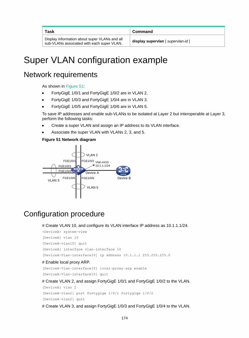
174
Task Command
Display information about super VLANs and all sub-VLANs associated with each super VLAN. display supervlan [ supervlan-id ]
Super VLAN configuration example Network requirements
As shown in Figure 51: • FortyGigE 1/0/1 and FortyGigE 1/0/2 are in VLAN 2. • FortyGigE 1/0/3 and FortyGigE 1/0/4 are in VLAN 3. • FortyGigE 1/0/5 and FortyGigE 1/0/6 are in VLAN 5.
To save IP addresses and enable sub-VLANs to be isolated at Layer 2 but interoperable at Layer 3, perform the following tasks: • Create a super VLAN and assign an IP address to its VLAN interface. • Associate the super VLAN with VLANs 2, 3, and 5.
Figure 51 Network diagram
Configuration procedure # Create VLAN 10, and configure its VLAN interface IP address as 10.1.1.1/24. <DeviceA> system-view
[DeviceA] vlan 10
[DeviceA-vlan10] quit
[DeviceA] interface vlan-interface 10
[DeviceA-Vlan-interface10] ip address 10.1.1.1 255.255.255.0
# Enable local proxy ARP. [DeviceA-Vlan-interface10] local-proxy-arp enable
[DeviceA-Vlan-interface10] quit
# Create VLAN 2, and assign FortyGigE 1/0/1 and FortyGigE 1/0/2 to the VLAN. [DeviceA] vlan 2
[DeviceA-vlan2] port fortygige 1/0/1 fortygige 1/0/2
[DeviceA-vlan2] quit
# Create VLAN 3, and assign FortyGigE 1/0/3 and FortyGigE 1/0/4 to the VLAN.
FGE1/0/1 FGE1/0/2
FGE1/0/3FGE1/0/4
FGE1/0/5 FGE1/0/6
Vlan-int1010.1.1.1/24
VLAN 2
VLAN 5
VLAN 3
Device ADevice B
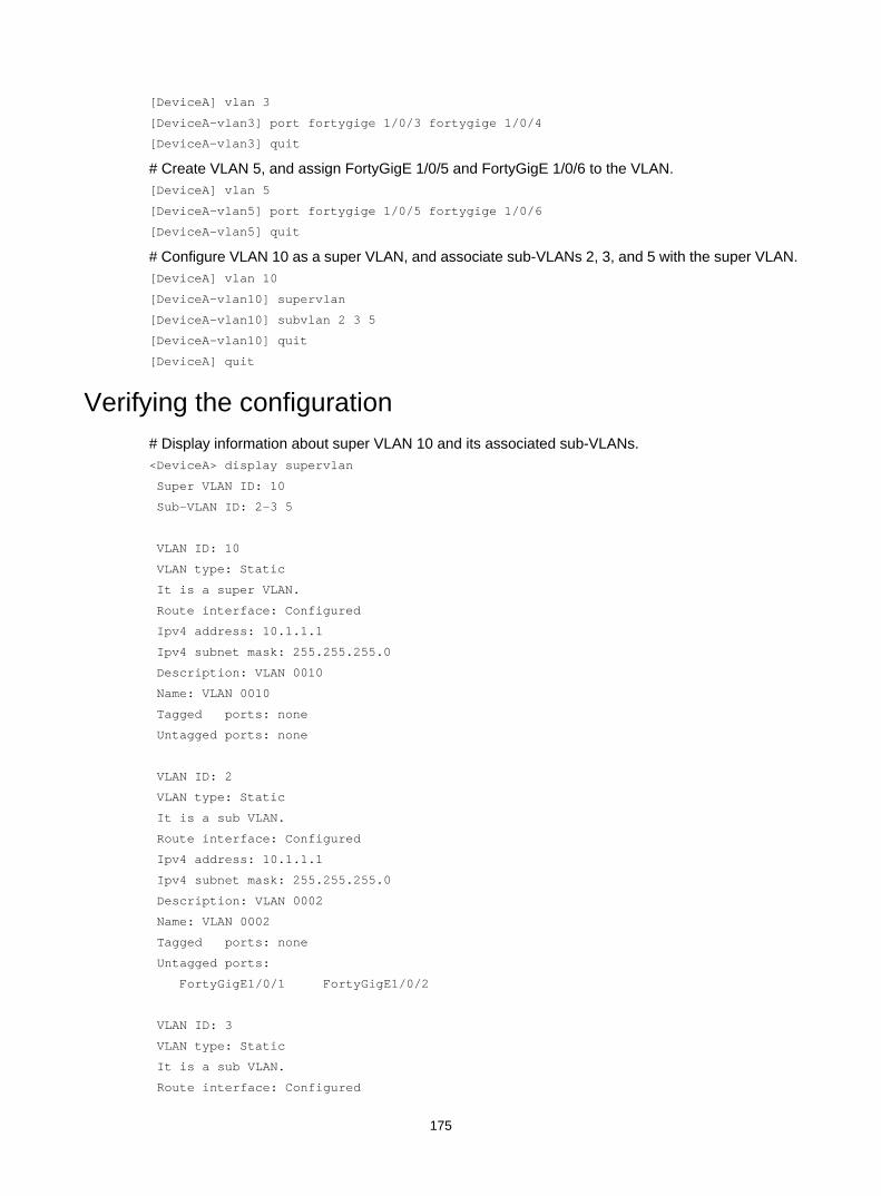
175
[DeviceA] vlan 3
[DeviceA-vlan3] port fortygige 1/0/3 fortygige 1/0/4
[DeviceA-vlan3] quit
# Create VLAN 5, and assign FortyGigE 1/0/5 and FortyGigE 1/0/6 to the VLAN. [DeviceA] vlan 5
[DeviceA-vlan5] port fortygige 1/0/5 fortygige 1/0/6
[DeviceA-vlan5] quit
# Configure VLAN 10 as a super VLAN, and associate sub-VLANs 2, 3, and 5 with the super VLAN. [DeviceA] vlan 10
[DeviceA-vlan10] supervlan
[DeviceA-vlan10] subvlan 2 3 5
[DeviceA-vlan10] quit
[DeviceA] quit
Verifying the configuration # Display information about super VLAN 10 and its associated sub-VLANs. <DeviceA> display supervlan
Super VLAN ID: 10
Sub-VLAN ID: 2-3 5
VLAN ID: 10
VLAN type: Static
It is a super VLAN.
Route interface: Configured
Ipv4 address: 10.1.1.1
Ipv4 subnet mask: 255.255.255.0
Description: VLAN 0010
Name: VLAN 0010
Tagged ports: none
Untagged ports: none
VLAN ID: 2
VLAN type: Static
It is a sub VLAN.
Route interface: Configured
Ipv4 address: 10.1.1.1
Ipv4 subnet mask: 255.255.255.0
Description: VLAN 0002
Name: VLAN 0002
Tagged ports: none
Untagged ports:
FortyGigE1/0/1 FortyGigE1/0/2
VLAN ID: 3
VLAN type: Static
It is a sub VLAN.
Route interface: Configured
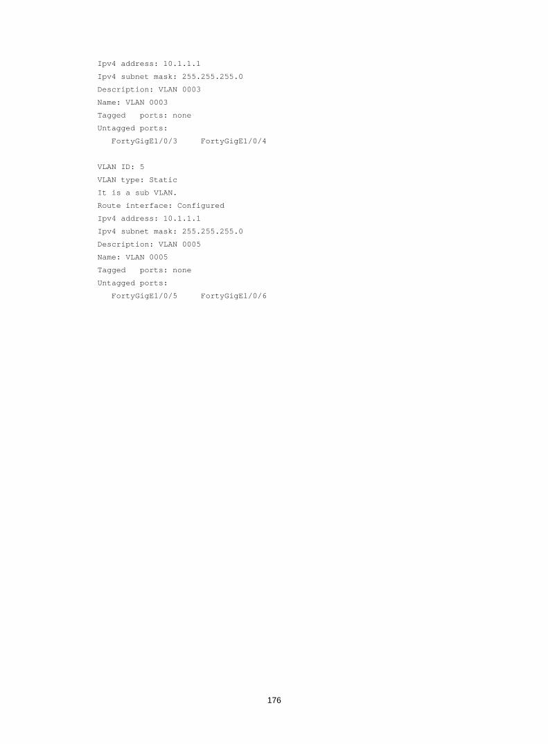
176
Ipv4 address: 10.1.1.1
Ipv4 subnet mask: 255.255.255.0
Description: VLAN 0003
Name: VLAN 0003
Tagged ports: none
Untagged ports:
FortyGigE1/0/3 FortyGigE1/0/4
VLAN ID: 5
VLAN type: Static
It is a sub VLAN.
Route interface: Configured
Ipv4 address: 10.1.1.1
Ipv4 subnet mask: 255.255.255.0
Description: VLAN 0005
Name: VLAN 0005
Tagged ports: none
Untagged ports:
FortyGigE1/0/5 FortyGigE1/0/6
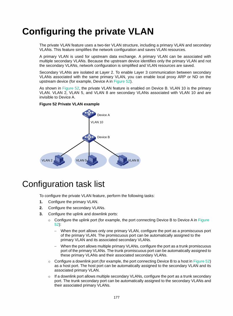
177
Configuring the private VLAN The private VLAN feature uses a two-tier VLAN structure, including a primary VLAN and secondary VLANs. This feature simplifies the network configuration and saves VLAN resources.
A primary VLAN is used for upstream data exchange. A primary VLAN can be associated with multiple secondary VLANs. Because the upstream device identifies only the primary VLAN and not the secondary VLANs, network configuration is simplified and VLAN resources are saved.
Secondary VLANs are isolated at Layer 2. To enable Layer 3 communication between secondary VLANs associated with the same primary VLAN, you can enable local proxy ARP or ND on the upstream device (for example, Device A in Figure 52).
As shown in Figure 52, the private VLAN feature is enabled on Device B. VLAN 10 is the primary VLAN. VLAN 2, VLAN 5, and VLAN 8 are secondary VLANs associated with VLAN 10 and are invisible to Device A.
Figure 52 Private VLAN example
Configuration task list To configure the private VLAN feature, perform the following tasks: 1. Configure the primary VLAN. 2. Configure the secondary VLANs. 3. Configure the uplink and downlink ports:
Configure the uplink port (for example, the port connecting Device B to Device A in Figure 52): − When the port allows only one primary VLAN, configure the port as a promiscuous port
of the primary VLAN. The promiscuous port can be automatically assigned to the primary VLAN and its associated secondary VLANs.
− When the port allows multiple primary VLANs, configure the port as a trunk promiscuous port of the primary VLANs. The trunk promiscuous port can be automatically assigned to these primary VLANs and their associated secondary VLANs.
Configure a downlink port (for example, the port connecting Device B to a host in Figure 52) as a host port. The host port can be automatically assigned to the secondary VLAN and its associated primary VLAN.
If a downlink port allows multiple secondary VLANs, configure the port as a trunk secondary port. The trunk secondary port can be automatically assigned to the secondary VLANs and their associated primary VLANs.
VLAN 2 VLAN 5 VLAN 8
VLAN 10
Device A
Device B
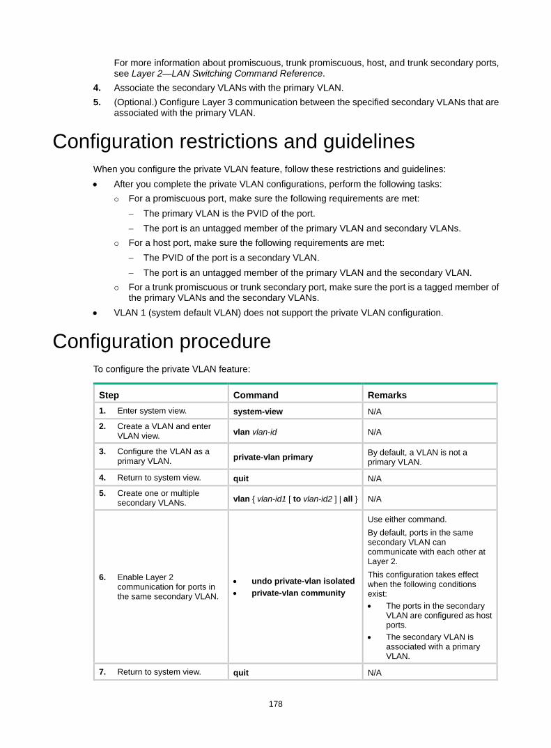
178
For more information about promiscuous, trunk promiscuous, host, and trunk secondary ports, see Layer 2—LAN Switching Command Reference.
4. Associate the secondary VLANs with the primary VLAN. 5. (Optional.) Configure Layer 3 communication between the specified secondary VLANs that are
associated with the primary VLAN.
Configuration restrictions and guidelines When you configure the private VLAN feature, follow these restrictions and guidelines: • After you complete the private VLAN configurations, perform the following tasks:
For a promiscuous port, make sure the following requirements are met: − The primary VLAN is the PVID of the port. − The port is an untagged member of the primary VLAN and secondary VLANs.
For a host port, make sure the following requirements are met: − The PVID of the port is a secondary VLAN. − The port is an untagged member of the primary VLAN and the secondary VLAN.
For a trunk promiscuous or trunk secondary port, make sure the port is a tagged member of the primary VLANs and the secondary VLANs.
• VLAN 1 (system default VLAN) does not support the private VLAN configuration.
Configuration procedure To configure the private VLAN feature:
Step Command Remarks 1. Enter system view. system-view N/A
2. Create a VLAN and enter VLAN view. vlan vlan-id N/A
3. Configure the VLAN as a primary VLAN. private-vlan primary By default, a VLAN is not a
primary VLAN.
4. Return to system view. quit N/A
5. Create one or multiple secondary VLANs. vlan { vlan-id1 [ to vlan-id2 ] | all } N/A
6. Enable Layer 2 communication for ports in the same secondary VLAN.
• undo private-vlan isolated • private-vlan community
Use either command. By default, ports in the same secondary VLAN can communicate with each other at Layer 2. This configuration takes effect when the following conditions exist: • The ports in the secondary
VLAN are configured as host ports.
• The secondary VLAN is associated with a primary VLAN.
7. Return to system view. quit N/A
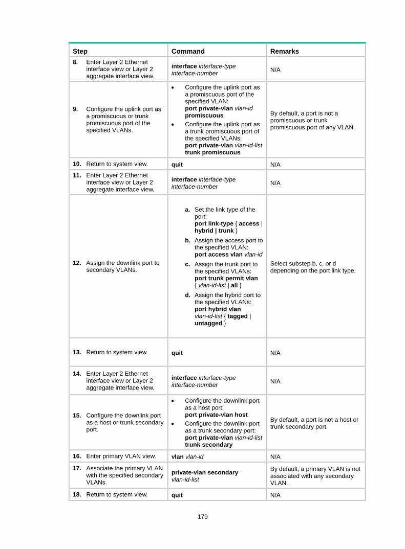
179
Step Command Remarks 8. Enter Layer 2 Ethernet
interface view or Layer 2 aggregate interface view.
interface interface-type interface-number N/A
9. Configure the uplink port as a promiscuous or trunk promiscuous port of the specified VLANs.
• Configure the uplink port as a promiscuous port of the specified VLAN: port private-vlan vlan-id promiscuous
• Configure the uplink port as a trunk promiscuous port of the specified VLANs: port private-vlan vlan-id-list trunk promiscuous
By default, a port is not a promiscuous or trunk promiscuous port of any VLAN.
10. Return to system view. quit N/A
11. Enter Layer 2 Ethernet interface view or Layer 2 aggregate interface view.
interface interface-type interface-number N/A
12. Assign the downlink port to secondary VLANs.
a. Set the link type of the port: port link-type { access | hybrid | trunk }
b. Assign the access port to the specified VLAN: port access vlan vlan-id
c. Assign the trunk port to the specified VLANs: port trunk permit vlan { vlan-id-list | all }
d. Assign the hybrid port to the specified VLANs: port hybrid vlan vlan-id-list { tagged | untagged }
Select substep b, c, or d depending on the port link type.
13. Return to system view. quit N/A
14. Enter Layer 2 Ethernet interface view or Layer 2 aggregate interface view.
interface interface-type interface-number N/A
15. Configure the downlink port as a host or trunk secondary port.
• Configure the downlink port as a host port: port private-vlan host
• Configure the downlink port as a trunk secondary port: port private-vlan vlan-id-list trunk secondary
By default, a port is not a host or trunk secondary port.
16. Enter primary VLAN view. vlan vlan-id N/A
17. Associate the primary VLAN with the specified secondary VLANs.
private-vlan secondary vlan-id-list
By default, a primary VLAN is not associated with any secondary VLAN.
18. Return to system view. quit N/A
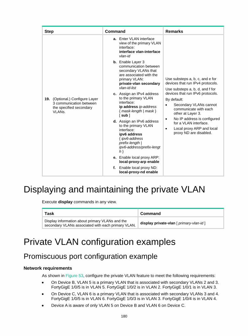
180
Step Command Remarks
19. (Optional.) Configure Layer 3 communication between the specified secondary VLANs.
a. Enter VLAN interface view of the primary VLAN interface: interface vlan-interface vlan-id
b. Enable Layer 3 communication between secondary VLANs that are associated with the primary VLAN: private-vlan secondary vlan-id-list
c. Assign an IPv4 address to the primary VLAN interface: ip address ip-address { mask-length | mask } [ sub ]
d. Assign an IPv6 address to the primary VLAN interface: ipv6 address { ipv6-address prefix-length | ipv6-address/prefix-length }
e. Enable local proxy ARP: local-proxy-arp enable
f. Enable local proxy ND: local-proxy-nd enable
Use substeps a, b, c, and e for devices that run IPv4 protocols. Use substeps a, b, d, and f for devices that run IPv6 protocols. By default: • Secondary VLANs cannot
communicate with each other at Layer 3.
• No IP address is configured for a VLAN interface.
• Local proxy ARP and local proxy ND are disabled.
Displaying and maintaining the private VLAN Execute display commands in any view.
Task Command Display information about primary VLANs and the secondary VLANs associated with each primary VLAN. display private-vlan [ primary-vlan-id ]
Private VLAN configuration examples Promiscuous port configuration example Network requirements
As shown in Figure 53, configure the private VLAN feature to meet the following requirements: • On Device B, VLAN 5 is a primary VLAN that is associated with secondary VLANs 2 and 3.
FortyGigE 1/0/5 is in VLAN 5. FortyGigE 1/0/2 is in VLAN 2. FortyGigE 1/0/1 is in VLAN 3. • On Device C, VLAN 6 is a primary VLAN that is associated with secondary VLANs 3 and 4.
FortyGigE 1/0/5 is in VLAN 6. FortyGigE 1/0/3 is in VLAN 3. FortyGigE 1/0/4 is in VLAN 4. • Device A is aware of only VLAN 5 on Device B and VLAN 6 on Device C.
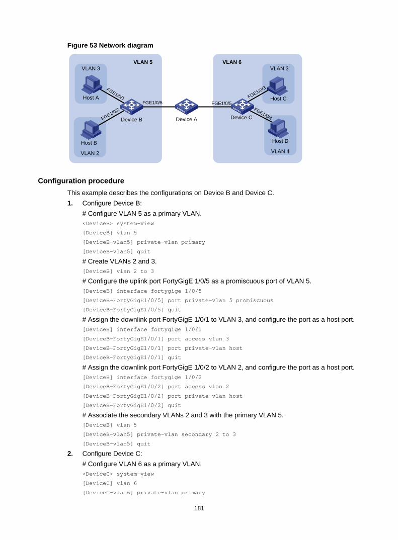
181
Figure 53 Network diagram
Configuration procedure This example describes the configurations on Device B and Device C. 1. Configure Device B:
# Configure VLAN 5 as a primary VLAN. <DeviceB> system-view
[DeviceB] vlan 5
[DeviceB-vlan5] private-vlan primary
[DeviceB-vlan5] quit
# Create VLANs 2 and 3. [DeviceB] vlan 2 to 3
# Configure the uplink port FortyGigE 1/0/5 as a promiscuous port of VLAN 5. [DeviceB] interface fortygige 1/0/5
[DeviceB-FortyGigE1/0/5] port private-vlan 5 promiscuous
[DeviceB-FortyGigE1/0/5] quit
# Assign the downlink port FortyGigE 1/0/1 to VLAN 3, and configure the port as a host port. [DeviceB] interface fortygige 1/0/1
[DeviceB-FortyGigE1/0/1] port access vlan 3
[DeviceB-FortyGigE1/0/1] port private-vlan host
[DeviceB-FortyGigE1/0/1] quit
# Assign the downlink port FortyGigE 1/0/2 to VLAN 2, and configure the port as a host port. [DeviceB] interface fortygige 1/0/2
[DeviceB-FortyGigE1/0/2] port access vlan 2
[DeviceB-FortyGigE1/0/2] port private-vlan host
[DeviceB-FortyGigE1/0/2] quit
# Associate the secondary VLANs 2 and 3 with the primary VLAN 5. [DeviceB] vlan 5
[DeviceB-vlan5] private-vlan secondary 2 to 3
[DeviceB-vlan5] quit
2. Configure Device C: # Configure VLAN 6 as a primary VLAN. <DeviceC> system-view
[DeviceC] vlan 6
[DeviceC–vlan6] private-vlan primary
FGE1/0/1
FGE1/0/2
VLAN 5
FGE1/0/3
FGE1/0/4
VLAN 6
FGE1/0/5 FGE1/0/5
Device ADevice B Device C
Host A
Host B
Host C
Host D
VLAN 3
VLAN 2
VLAN 3
VLAN 4
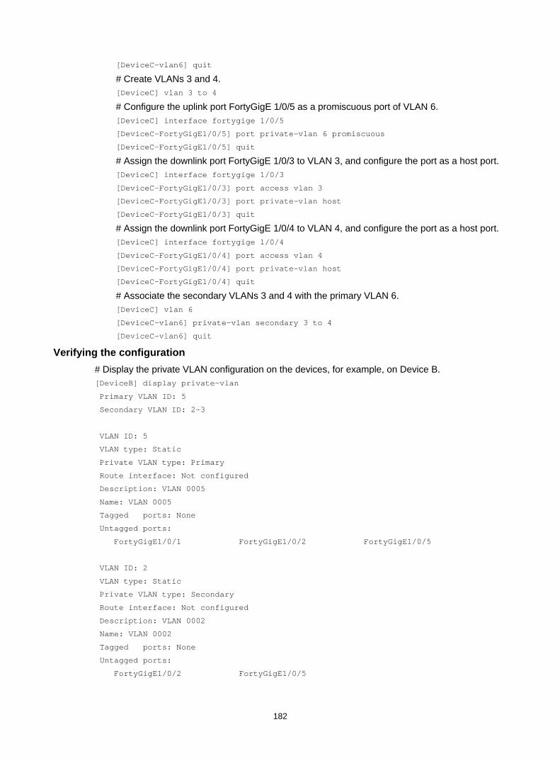
182
[DeviceC–vlan6] quit
# Create VLANs 3 and 4. [DeviceC] vlan 3 to 4
# Configure the uplink port FortyGigE 1/0/5 as a promiscuous port of VLAN 6. [DeviceC] interface fortygige 1/0/5
[DeviceC-FortyGigE1/0/5] port private-vlan 6 promiscuous
[DeviceC-FortyGigE1/0/5] quit
# Assign the downlink port FortyGigE 1/0/3 to VLAN 3, and configure the port as a host port. [DeviceC] interface fortygige 1/0/3
[DeviceC-FortyGigE1/0/3] port access vlan 3
[DeviceC-FortyGigE1/0/3] port private-vlan host
[DeviceC-FortyGigE1/0/3] quit
# Assign the downlink port FortyGigE 1/0/4 to VLAN 4, and configure the port as a host port. [DeviceC] interface fortygige 1/0/4
[DeviceC-FortyGigE1/0/4] port access vlan 4
[DeviceC-FortyGigE1/0/4] port private-vlan host
[DeviceC-FortyGigE1/0/4] quit
# Associate the secondary VLANs 3 and 4 with the primary VLAN 6. [DeviceC] vlan 6
[DeviceC-vlan6] private-vlan secondary 3 to 4
[DeviceC-vlan6] quit
Verifying the configuration # Display the private VLAN configuration on the devices, for example, on Device B. [DeviceB] display private-vlan
Primary VLAN ID: 5
Secondary VLAN ID: 2-3
VLAN ID: 5
VLAN type: Static
Private VLAN type: Primary
Route interface: Not configured
Description: VLAN 0005
Name: VLAN 0005
Tagged ports: None
Untagged ports:
FortyGigE1/0/1 FortyGigE1/0/2 FortyGigE1/0/5
VLAN ID: 2
VLAN type: Static
Private VLAN type: Secondary
Route interface: Not configured
Description: VLAN 0002
Name: VLAN 0002
Tagged ports: None
Untagged ports:
FortyGigE1/0/2 FortyGigE1/0/5
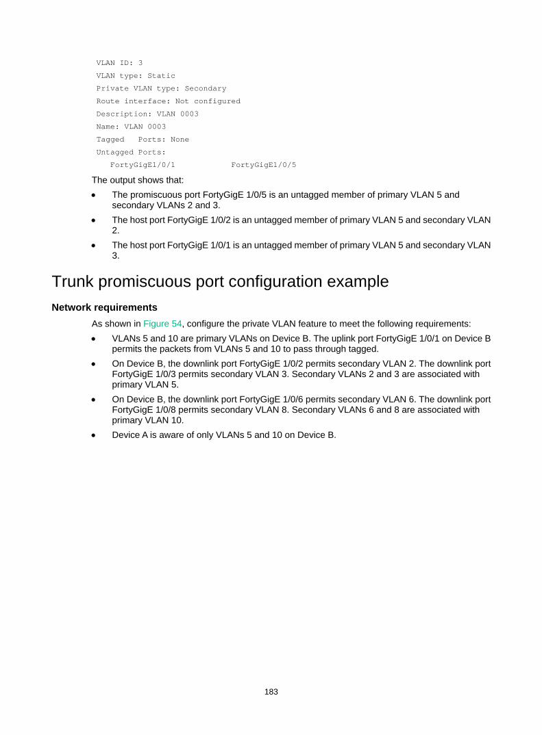
183
VLAN ID: 3
VLAN type: Static
Private VLAN type: Secondary
Route interface: Not configured
Description: VLAN 0003
Name: VLAN 0003
Tagged Ports: None
Untagged Ports:
FortyGigE1/0/1 FortyGigE1/0/5
The output shows that: • The promiscuous port FortyGigE 1/0/5 is an untagged member of primary VLAN 5 and
secondary VLANs 2 and 3. • The host port FortyGigE 1/0/2 is an untagged member of primary VLAN 5 and secondary VLAN
2. • The host port FortyGigE 1/0/1 is an untagged member of primary VLAN 5 and secondary VLAN
3.
Trunk promiscuous port configuration example Network requirements
As shown in Figure 54, configure the private VLAN feature to meet the following requirements: • VLANs 5 and 10 are primary VLANs on Device B. The uplink port FortyGigE 1/0/1 on Device B
permits the packets from VLANs 5 and 10 to pass through tagged. • On Device B, the downlink port FortyGigE 1/0/2 permits secondary VLAN 2. The downlink port
FortyGigE 1/0/3 permits secondary VLAN 3. Secondary VLANs 2 and 3 are associated with primary VLAN 5.
• On Device B, the downlink port FortyGigE 1/0/6 permits secondary VLAN 6. The downlink port FortyGigE 1/0/8 permits secondary VLAN 8. Secondary VLANs 6 and 8 are associated with primary VLAN 10.
• Device A is aware of only VLANs 5 and 10 on Device B.
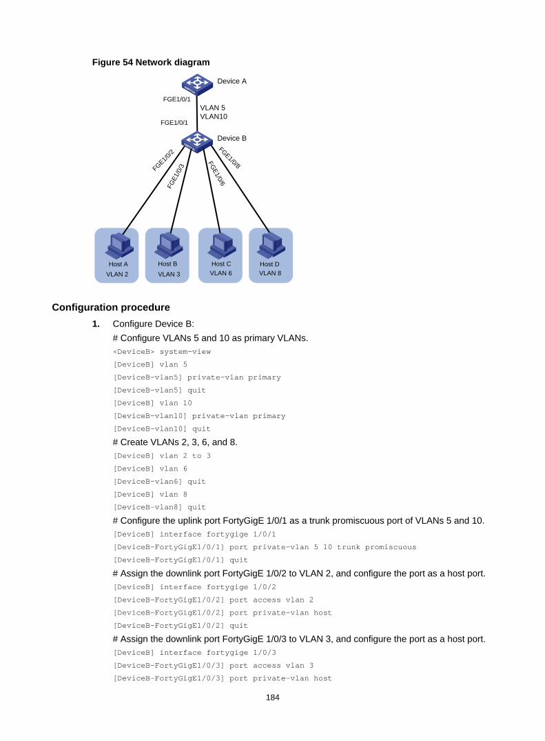
184
Figure 54 Network diagram
Configuration procedure 1. Configure Device B:
# Configure VLANs 5 and 10 as primary VLANs. <DeviceB> system-view
[DeviceB] vlan 5
[DeviceB-vlan5] private-vlan primary
[DeviceB-vlan5] quit
[DeviceB] vlan 10
[DeviceB-vlan10] private-vlan primary
[DeviceB-vlan10] quit
# Create VLANs 2, 3, 6, and 8. [DeviceB] vlan 2 to 3
[DeviceB] vlan 6
[DeviceB-vlan6] quit
[DeviceB] vlan 8
[DeviceB-vlan8] quit
# Configure the uplink port FortyGigE 1/0/1 as a trunk promiscuous port of VLANs 5 and 10. [DeviceB] interface fortygige 1/0/1
[DeviceB-FortyGigE1/0/1] port private-vlan 5 10 trunk promiscuous
[DeviceB-FortyGigE1/0/1] quit
# Assign the downlink port FortyGigE 1/0/2 to VLAN 2, and configure the port as a host port. [DeviceB] interface fortygige 1/0/2
[DeviceB-FortyGigE1/0/2] port access vlan 2
[DeviceB-FortyGigE1/0/2] port private-vlan host
[DeviceB-FortyGigE1/0/2] quit
# Assign the downlink port FortyGigE 1/0/3 to VLAN 3, and configure the port as a host port. [DeviceB] interface fortygige 1/0/3
[DeviceB-FortyGigE1/0/3] port access vlan 3
[DeviceB-FortyGigE1/0/3] port private-vlan host
VLAN 6 VLAN 8Host C Host D
Device B
Device A
VLAN 5 VLAN10
FGE1/0/1
FGE1/0/1
FGE1/0/2
FGE1
/0/3
FGE1/0/6
FGE1/0/8
VLAN 2Host A
VLAN 3Host B
185
[DeviceB-FortyGigE1/0/3] quit
# Associate the secondary VLANs 2 and 3 with the primary VLAN 5. [DeviceB] vlan 5
[DeviceB-vlan5] private-vlan secondary 2 to 3
[DeviceB-vlan5] quit
# Assign the downlink port FortyGigE 1/0/6 to VLAN 6, and configure the port as a host port. [DeviceB] interface fortygige 1/0/6
[DeviceB-FortyGigE1/0/6] port access vlan 6
[DeviceB-FortyGigE1/0/6] port private-vlan host
[DeviceB-FortyGigE1/0/6] quit
# Assign the downlink port FortyGigE 1/0/8 to VLAN 8, and configure the port as a host port. [DeviceB] interface fortygige 1/0/8
[DeviceB-FortyGigE1/0/8] port access vlan 8
[DeviceB-FortyGigE1/0/8] port private-vlan host
[DeviceB-FortyGigE1/0/8] quit
# Associate the secondary VLANs 6 and 8 with the primary VLAN 10. [DeviceB] vlan 10
[DeviceB-vlan10] private-vlan secondary 6 8
[DeviceB-vlan10] quit
2. Configure Device A: # Create VLANs 5 and 10. [DeviceA] vlan 5
[DeviceA-vlan5] quit
[DeviceA] vlan 10
[DeviceA-vlan10] quit
# Configure FortyGigE 1/0/1 as a hybrid port, and assign it to VLANs 5 and 10 as a tagged VLAN member. [DeviceA] interface fortygige 1/0/1
[DeviceA-FortyGigE1/0/1] port link-type hybrid
[DeviceA-FortyGigE1/0/1] port hybrid vlan 5 10 tagged
[DeviceA-FortyGigE1/0/1] quit
Verifying the configuration # Display primary VLAN configurations on Device B. The following output uses primary VLAN 5 as an example. [DeviceB] display private-vlan 5
Primary VLAN ID: 5
Secondary VLAN ID: 2-3
VLAN ID: 5
VLAN type: Static
Private VLAN type: Primary
Route interface: Not configured
Description: VLAN 0005
Name: VLAN 0005
Tagged ports:
FortyGigE1/0/1
Untagged ports:
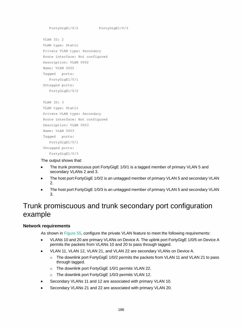
186
FortyGigE1/0/2 FortyGigE1/0/3
VLAN ID: 2
VLAN type: Static
Private VLAN type: Secondary
Route interface: Not configured
Description: VLAN 0002
Name: VLAN 0002
Tagged ports:
FortyGigE1/0/1
Untagged ports:
FortyGigE1/0/2
VLAN ID: 3
VLAN type: Static
Private VLAN type: Secondary
Route interface: Not configured
Description: VLAN 0003
Name: VLAN 0003
Tagged ports:
FortyGigE1/0/1
Untagged ports:
FortyGigE1/0/3
The output shows that: • The trunk promiscuous port FortyGigE 1/0/1 is a tagged member of primary VLAN 5 and
secondary VLANs 2 and 3. • The host port FortyGigE 1/0/2 is an untagged member of primary VLAN 5 and secondary VLAN
2. • The host port FortyGigE 1/0/3 is an untagged member of primary VLAN 5 and secondary VLAN
3.
Trunk promiscuous and trunk secondary port configuration example Network requirements
As shown in Figure 55, configure the private VLAN feature to meet the following requirements: • VLANs 10 and 20 are primary VLANs on Device A. The uplink port FortyGigE 1/0/5 on Device A
permits the packets from VLANs 10 and 20 to pass through tagged. • VLAN 11, VLAN 12, VLAN 21, and VLAN 22 are secondary VLANs on Device A.
The downlink port FortyGigE 1/0/2 permits the packets from VLAN 11 and VLAN 21 to pass through tagged.
The downlink port FortyGigE 1/0/1 permits VLAN 22. The downlink port FortyGigE 1/0/3 permits VLAN 12.
• Secondary VLANs 11 and 12 are associated with primary VLAN 10. • Secondary VLANs 21 and 22 are associated with primary VLAN 20.
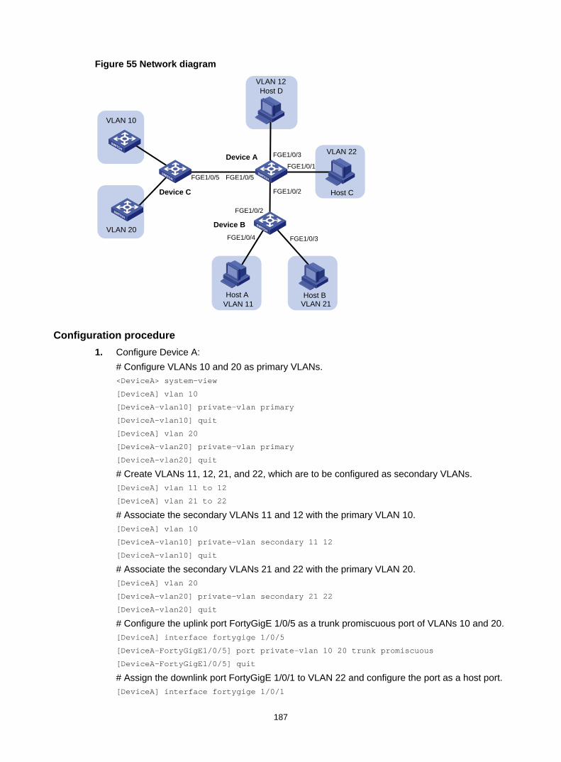
187
Figure 55 Network diagram
Configuration procedure 1. Configure Device A:
# Configure VLANs 10 and 20 as primary VLANs. <DeviceA> system-view
[DeviceA] vlan 10
[DeviceA-vlan10] private-vlan primary
[DeviceA-vlan10] quit
[DeviceA] vlan 20
[DeviceA-vlan20] private-vlan primary
[DeviceA-vlan20] quit
# Create VLANs 11, 12, 21, and 22, which are to be configured as secondary VLANs. [DeviceA] vlan 11 to 12
[DeviceA] vlan 21 to 22
# Associate the secondary VLANs 11 and 12 with the primary VLAN 10. [DeviceA] vlan 10
[DeviceA-vlan10] private-vlan secondary 11 12
[DeviceA-vlan10] quit
# Associate the secondary VLANs 21 and 22 with the primary VLAN 20. [DeviceA] vlan 20
[DeviceA-vlan20] private-vlan secondary 21 22
[DeviceA-vlan20] quit
# Configure the uplink port FortyGigE 1/0/5 as a trunk promiscuous port of VLANs 10 and 20. [DeviceA] interface fortygige 1/0/5
[DeviceA-FortyGigE1/0/5] port private-vlan 10 20 trunk promiscuous
[DeviceA-FortyGigE1/0/5] quit
# Assign the downlink port FortyGigE 1/0/1 to VLAN 22 and configure the port as a host port. [DeviceA] interface fortygige 1/0/1
VLAN 10
VLAN 20
VLAN 12
VLAN 11 VLAN 21
VLAN 22
Host A Host B
Host C
Host D
FGE1/0/5 FGE1/0/5
FGE1/0/2
FGE1/0/1
FGE1/0/3Device A
Device C
FGE1/0/2
FGE1/0/3FGE1/0/4
Device B
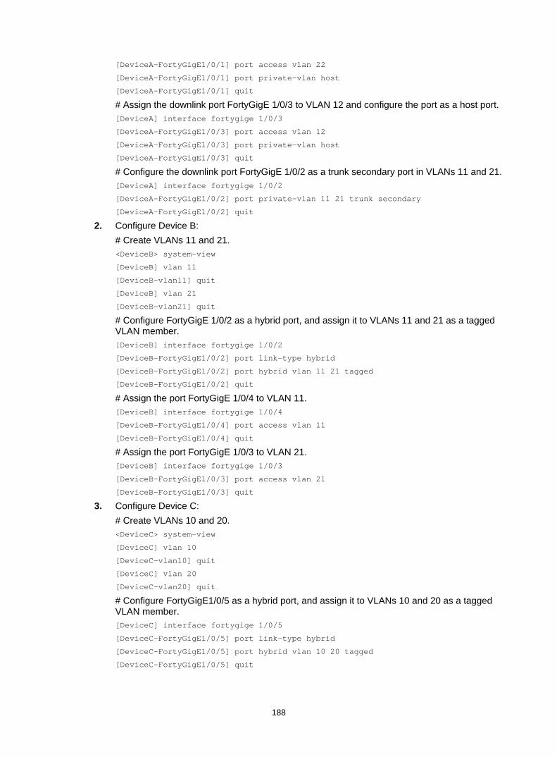
188
[DeviceA-FortyGigE1/0/1] port access vlan 22
[DeviceA-FortyGigE1/0/1] port private-vlan host
[DeviceA-FortyGigE1/0/1] quit
# Assign the downlink port FortyGigE 1/0/3 to VLAN 12 and configure the port as a host port. [DeviceA] interface fortygige 1/0/3
[DeviceA-FortyGigE1/0/3] port access vlan 12
[DeviceA-FortyGigE1/0/3] port private-vlan host
[DeviceA-FortyGigE1/0/3] quit
# Configure the downlink port FortyGigE 1/0/2 as a trunk secondary port in VLANs 11 and 21. [DeviceA] interface fortygige 1/0/2
[DeviceA-FortyGigE1/0/2] port private-vlan 11 21 trunk secondary
[DeviceA-FortyGigE1/0/2] quit
2. Configure Device B: # Create VLANs 11 and 21. <DeviceB> system-view
[DeviceB] vlan 11
[DeviceB-vlan11] quit
[DeviceB] vlan 21
[DeviceB-vlan21] quit
# Configure FortyGigE 1/0/2 as a hybrid port, and assign it to VLANs 11 and 21 as a tagged VLAN member. [DeviceB] interface fortygige 1/0/2
[DeviceB-FortyGigE1/0/2] port link-type hybrid
[DeviceB-FortyGigE1/0/2] port hybrid vlan 11 21 tagged
[DeviceB-FortyGigE1/0/2] quit
# Assign the port FortyGigE 1/0/4 to VLAN 11. [DeviceB] interface fortygige 1/0/4
[DeviceB-FortyGigE1/0/4] port access vlan 11
[DeviceB-FortyGigE1/0/4] quit
# Assign the port FortyGigE 1/0/3 to VLAN 21. [DeviceB] interface fortygige 1/0/3
[DeviceB-FortyGigE1/0/3] port access vlan 21
[DeviceB-FortyGigE1/0/3] quit
3. Configure Device C: # Create VLANs 10 and 20. <DeviceC> system-view
[DeviceC] vlan 10
[DeviceC-vlan10] quit
[DeviceC] vlan 20
[DeviceC-vlan20] quit
# Configure FortyGigE1/0/5 as a hybrid port, and assign it to VLANs 10 and 20 as a tagged VLAN member. [DeviceC] interface fortygige 1/0/5
[DeviceC-FortyGigE1/0/5] port link-type hybrid
[DeviceC-FortyGigE1/0/5] port hybrid vlan 10 20 tagged
[DeviceC-FortyGigE1/0/5] quit
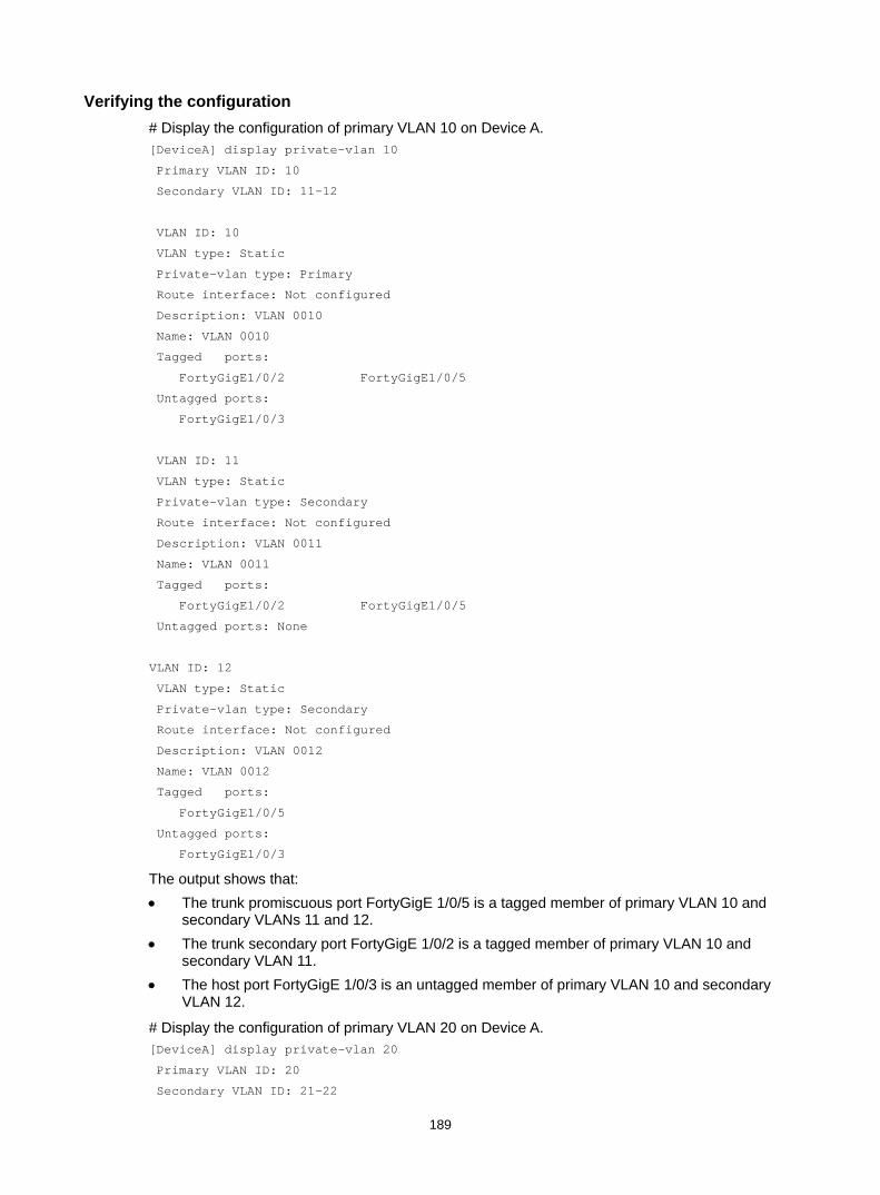
189
Verifying the configuration # Display the configuration of primary VLAN 10 on Device A. [DeviceA] display private-vlan 10
Primary VLAN ID: 10
Secondary VLAN ID: 11-12
VLAN ID: 10
VLAN type: Static
Private-vlan type: Primary
Route interface: Not configured
Description: VLAN 0010
Name: VLAN 0010
Tagged ports:
FortyGigE1/0/2 FortyGigE1/0/5
Untagged ports:
FortyGigE1/0/3
VLAN ID: 11
VLAN type: Static
Private-vlan type: Secondary
Route interface: Not configured
Description: VLAN 0011
Name: VLAN 0011
Tagged ports:
FortyGigE1/0/2 FortyGigE1/0/5
Untagged ports: None
VLAN ID: 12
VLAN type: Static
Private-vlan type: Secondary
Route interface: Not configured
Description: VLAN 0012
Name: VLAN 0012
Tagged ports:
FortyGigE1/0/5
Untagged ports:
FortyGigE1/0/3
The output shows that: • The trunk promiscuous port FortyGigE 1/0/5 is a tagged member of primary VLAN 10 and
secondary VLANs 11 and 12. • The trunk secondary port FortyGigE 1/0/2 is a tagged member of primary VLAN 10 and
secondary VLAN 11. • The host port FortyGigE 1/0/3 is an untagged member of primary VLAN 10 and secondary
VLAN 12.
# Display the configuration of primary VLAN 20 on Device A. [DeviceA] display private-vlan 20
Primary VLAN ID: 20
Secondary VLAN ID: 21-22
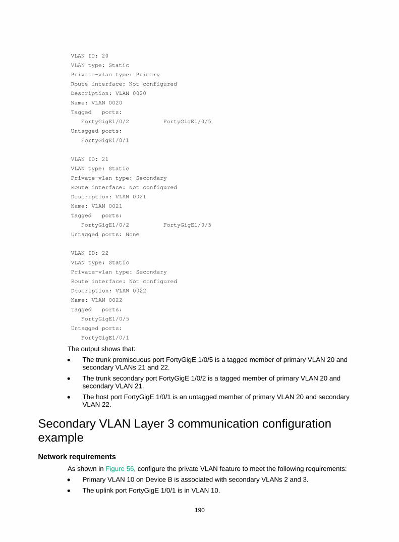
190
VLAN ID: 20
VLAN type: Static
Private-vlan type: Primary
Route interface: Not configured
Description: VLAN 0020
Name: VLAN 0020
Tagged ports:
FortyGigE1/0/2 FortyGigE1/0/5
Untagged ports:
FortyGigE1/0/1
VLAN ID: 21
VLAN type: Static
Private-vlan type: Secondary
Route interface: Not configured
Description: VLAN 0021
Name: VLAN 0021
Tagged ports:
FortyGigE1/0/2 FortyGigE1/0/5
Untagged ports: None
VLAN ID: 22
VLAN type: Static
Private-vlan type: Secondary
Route interface: Not configured
Description: VLAN 0022
Name: VLAN 0022
Tagged ports:
FortyGigE1/0/5
Untagged ports:
FortyGigE1/0/1
The output shows that: • The trunk promiscuous port FortyGigE 1/0/5 is a tagged member of primary VLAN 20 and
secondary VLANs 21 and 22. • The trunk secondary port FortyGigE 1/0/2 is a tagged member of primary VLAN 20 and
secondary VLAN 21. • The host port FortyGigE 1/0/1 is an untagged member of primary VLAN 20 and secondary
VLAN 22.
Secondary VLAN Layer 3 communication configuration example Network requirements
As shown in Figure 56, configure the private VLAN feature to meet the following requirements: • Primary VLAN 10 on Device B is associated with secondary VLANs 2 and 3. • The uplink port FortyGigE 1/0/1 is in VLAN 10.

191
• The IP address of VLAN-interface 10 is 192.168.1.1/24. • The ports FortyGigE 1/0/2 and FortyGigE 1/0/3 are in VLAN 2 and VLAN 3, respectively. • Secondary VLANs are isolated at Layer 2 but interoperable at Layer 3.
Figure 56 Network diagram
Configuration procedure # Create VLAN 2 and VLAN 3. <DeviceB> system-view
[DeviceB] vlan 2 to 3
# Configure VLAN 10 as a primary VLAN, and associate VLAN 2 and VLAN 3 with primary VLAN 10 as secondary VLANs. [DeviceB] vlan 10
[DeviceB-vlan10] private-vlan primary
[DeviceB-vlan10] private-vlan secondary 2 3
[DeviceB-vlan10] quit
# Configure the uplink port FortyGigE 1/0/1 as a promiscuous port of VLAN 10. [DeviceB] interface fortygige 1/0/1
[DeviceB-FortyGigE1/0/1] port private-vlan 10 promiscuous
[DeviceB-FortyGigE1/0/1] quit
# Assign the downlink port FortyGigE 1/0/2 to VLAN 2, and configure the port as a host port. [DeviceB] interface fortygige 1/0/2
[DeviceB-FortyGigE1/0/2] port access vlan 2
[DeviceB-FortyGigE1/0/2] port private-vlan host
[DeviceB-FortyGigE1/0/2] quit
# Assign the downlink port FortyGigE 1/0/3 to VLAN 3, and configure the port as a host port. [DeviceB] interface fortygige 1/0/3
[DeviceB-FortyGigE1/0/3] port access vlan 3
[DeviceB-FortyGigE1/0/3] port private-vlan host
[DeviceB-FortyGigE1/0/3] quit
# Enable Layer 3 communication between secondary VLANs 2 and 3 that are associated with primary VLAN 10. [DeviceB] interface vlan-interface 10
[DeviceB-Vlan-interface10] private-vlan secondary 2 3
# Assign the IP address 192.168.1.1/24 to VLAN-interface 10. [DeviceB-Vlan-interface10] ip address 192.168.1.1 255.255.255.0
VLAN 2
FGE1/0/3FGE1/0/2
Device BVlan-int10192.168.1.1/24
VLAN 3
Device A
FGE1/0/1
VLAN 10
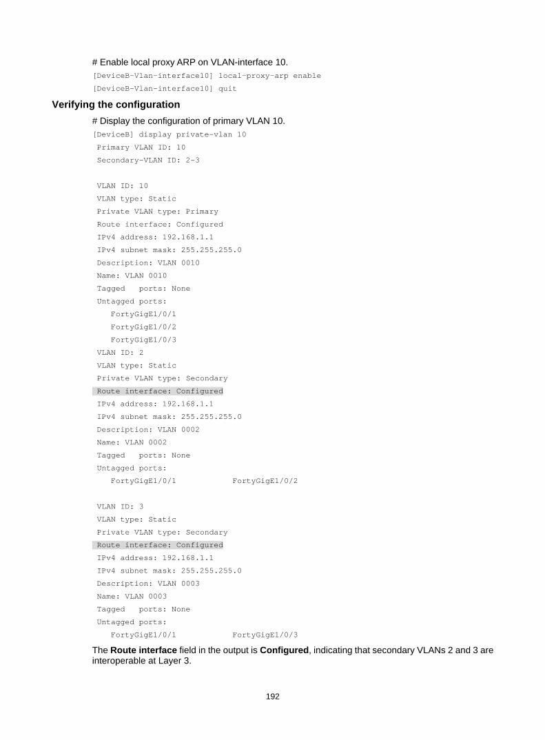
192
# Enable local proxy ARP on VLAN-interface 10. [DeviceB-Vlan-interface10] local-proxy-arp enable
[DeviceB-Vlan-interface10] quit
Verifying the configuration # Display the configuration of primary VLAN 10. [DeviceB] display private-vlan 10
Primary VLAN ID: 10
Secondary-VLAN ID: 2-3
VLAN ID: 10
VLAN type: Static
Private VLAN type: Primary
Route interface: Configured
IPv4 address: 192.168.1.1
IPv4 subnet mask: 255.255.255.0
Description: VLAN 0010
Name: VLAN 0010
Tagged ports: None
Untagged ports:
FortyGigE1/0/1
FortyGigE1/0/2
FortyGigE1/0/3
VLAN ID: 2
VLAN type: Static
Private VLAN type: Secondary
Route interface: Configured
IPv4 address: 192.168.1.1
IPv4 subnet mask: 255.255.255.0
Description: VLAN 0002
Name: VLAN 0002
Tagged ports: None
Untagged ports:
FortyGigE1/0/1 FortyGigE1/0/2
VLAN ID: 3
VLAN type: Static
Private VLAN type: Secondary
Route interface: Configured
IPv4 address: 192.168.1.1
IPv4 subnet mask: 255.255.255.0
Description: VLAN 0003
Name: VLAN 0003
Tagged ports: None
Untagged ports:
FortyGigE1/0/1 FortyGigE1/0/3
The Route interface field in the output is Configured, indicating that secondary VLANs 2 and 3 are interoperable at Layer 3.

193
Configuring voice VLANs Overview
A voice VLAN is used for transmitting voice traffic. When ports that connect to voice devices are assigned to a voice VLAN, the system can configure QoS parameters for voice packets to ensure higher transmission priority and sound voice quality.
Common voice devices include IP phones and integrated access devices (IADs). This chapter uses IP phone as an example.
For an IP phone to access a device, the device must perform the following operations: • Identify the IP phone in the network and obtain the MAC address of the IP phone. • Advertise the voice VLAN information to the IP phone.
After receiving the voice VLAN information, the IP phone can perform automatic configuration, so the voice packets sent from the IP phone can be transmitted within the voice VLAN.
Methods of identifying IP phones Devices can use the OUI addresses or LLDP to identify IP phones.
Identifying IP phones through OUI addresses A device determines whether a received packet is a voice packet based on its source MAC address. A packet whose source MAC address complies with any of the Organizationally Unique Identifier (OUI) addresses of the voice devices is regarded as voice traffic.
You can use system default OUI addresses (see Table 11) or configure OUI addresses for the device. You can manually remove or add the system default OUI addresses.
The switch supports 128 OUI addresses, including system default OUI addresses.
Table 11 Default OUI addresses
Number OUI address Vendor 1 0001-E300-0000 Siemens phone
2 0003-6B00-0000 Cisco phone
3 0004-0D00-0000 Avaya phone
4 00D0-1E00-0000 Pingtel phone
5 0060-B900-0000 Philips/NEC phone
6 00E0-7500-0000 Polycom phone
7 00E0-BB00-0000 3Com phone
Typically, an OUI address refers to the first 24 bits of a MAC address (in binary notation) and is a globally unique identifier that IEEE assigns to a vendor. However, OUI addresses in this chapter are addresses that the system uses to determine whether a received packet is a voice packet. They are the logical AND results of the mac-address and oui-mask arguments in the voice-vlan mac-address command.

194
Automatically identifying IP phones through LLDP When you use OUI addresses to identify IP phones, the number of OUI addresses that can be configured is limited. Additionally, when there are plenty of IP phones in the network, you must configure many OUI addresses. If IP phones support LLDP, configure LLDP on the device for automatic IP phone discovery. For more information, see "Enabling LLDP for automatic IP phone discovery."
Advertising the voice VLAN information to IP phones
Figure 57 shows the workflow of advertising the voice VLAN information to IP phones.
Figure 57 Workflow of advertising the voice VLAN information to IP phones
After receiving the voice VLAN information, the IP phone automatically completes the voice VLAN configuration. • If the voice VLAN configuration is based on the received LLDP-MED TLVs or CDP packets, the
IP phone will send out packets tagged with the advertised voice VLAN ID. The voice packets will be forwarded in the voice VLAN. For more information about configuring LLDP or CDP, see "Configuring LLDP or CDP to advertise a voice VLAN." For more information about LLDP and CDP compatibility, see "Configuring LLDP."
• If the voice VLAN configuration is based on the authorization VLAN information, the IP phone will send out packets tagged with the advertised authorization VLAN ID. The voice packets will be forwarded in the authorization VLAN. For more information about advertising the authorization VLAN information to IP phones, see "Dynamically advertising an authorization VLAN through LLDP or CDP." For more information about authorization VLANs, see Security Configuration Guide.
• If the voice VLAN configuration is based on the voice VLAN information of the accessing port, the voice traffic from the IP phone will be forwarded in the voice VLAN of the accessing port. Whether the voice packets are tagged depends on the voice VLAN configuration of the accessing port. For more information about configuring a voice VLAN on a port, see "Configuring a voice VLAN on a port."
Is the authorization VLAN received from the
authentication server?
Is LLDP/CDP configured to advertise the voice VLAN
ID?
Yes Advertise thevoice VLAN ID to the IP
phone
No
YesAdvertise the
authorization VLAN to to the IP phone
No
Advertise the voice VLAN configured on the port to the
IP phone
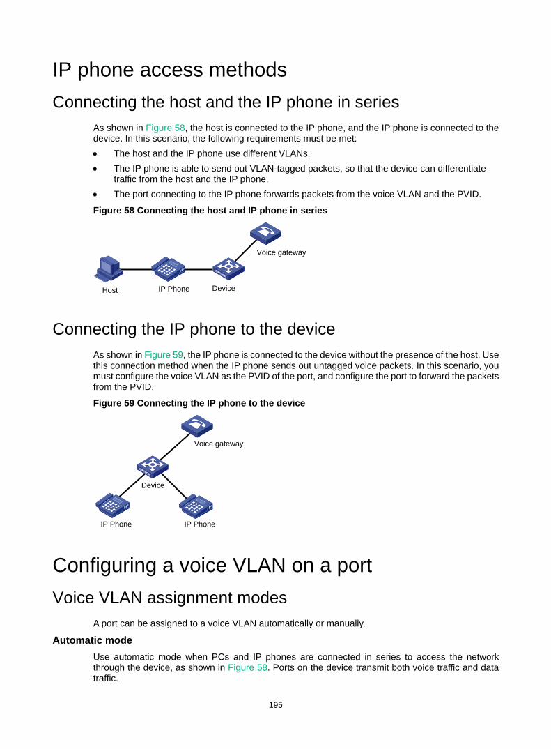
195
IP phone access methods Connecting the host and the IP phone in series
As shown in Figure 58, the host is connected to the IP phone, and the IP phone is connected to the device. In this scenario, the following requirements must be met: • The host and the IP phone use different VLANs. • The IP phone is able to send out VLAN-tagged packets, so that the device can differentiate
traffic from the host and the IP phone. • The port connecting to the IP phone forwards packets from the voice VLAN and the PVID.
Figure 58 Connecting the host and IP phone in series
Connecting the IP phone to the device As shown in Figure 59, the IP phone is connected to the device without the presence of the host. Use this connection method when the IP phone sends out untagged voice packets. In this scenario, you must configure the voice VLAN as the PVID of the port, and configure the port to forward the packets from the PVID.
Figure 59 Connecting the IP phone to the device
Configuring a voice VLAN on a port Voice VLAN assignment modes
A port can be assigned to a voice VLAN automatically or manually.
Automatic mode Use automatic mode when PCs and IP phones are connected in series to access the network through the device, as shown in Figure 58. Ports on the device transmit both voice traffic and data traffic.
Host IP Phone Device
Voice gateway
IP Phone
Device
Voice gateway
IP Phone
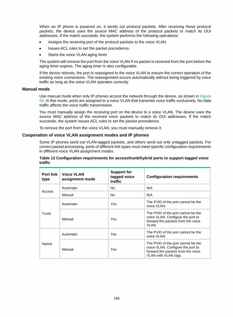
196
When an IP phone is powered on, it sends out protocol packets. After receiving these protocol packets, the device uses the source MAC address of the protocol packets to match its OUI addresses. If the match succeeds, the system performs the following operations: • Assigns the receiving port of the protocol packets to the voice VLAN. • Issues ACL rules to set the packet precedence. • Starts the voice VLAN aging timer.
The system will remove the port from the voice VLAN if no packet is received from the port before the aging timer expires. The aging timer is also configurable.
If the device reboots, the port is reassigned to the voice VLAN to ensure the correct operation of the existing voice connections. The reassignment occurs automatically without being triggered by voice traffic as long as the voice VLAN operates correctly.
Manual mode Use manual mode when only IP phones access the network through the device, as shown in Figure 59. In this mode, ports are assigned to a voice VLAN that transmits voice traffic exclusively. No data traffic affects the voice traffic transmission.
You must manually assign the receiving port on the device to a voice VLAN. The device uses the source MAC address of the received voice packets to match its OUI addresses. If the match succeeds, the system issues ACL rules to set the packet precedence.
To remove the port from the voice VLAN, you must manually remove it.
Cooperation of voice VLAN assignment modes and IP phones Some IP phones send out VLAN-tagged packets, and others send out only untagged packets. For correct packet processing, ports of different link types must meet specific configuration requirements in different voice VLAN assignment modes.
Table 12 Configuration requirements for access/trunk/hybrid ports to support tagged voice traffic
Port link type
Voice VLAN assignment mode
Support for tagged voice traffic
Configuration requirements
Access Automatic No N/A
Manual No N/A
Trunk
Automatic Yes The PVID of the port cannot be the voice VLAN.
Manual Yes
The PVID of the port cannot be the voice VLAN. Configure the port to forward the packets from the voice VLAN.
Hybrid
Automatic Yes The PVID of the port cannot be the voice VLAN.
Manual Yes
The PVID of the port cannot be the voice VLAN. Configure the port to forward the packets from the voice VLAN with VLAN tags.
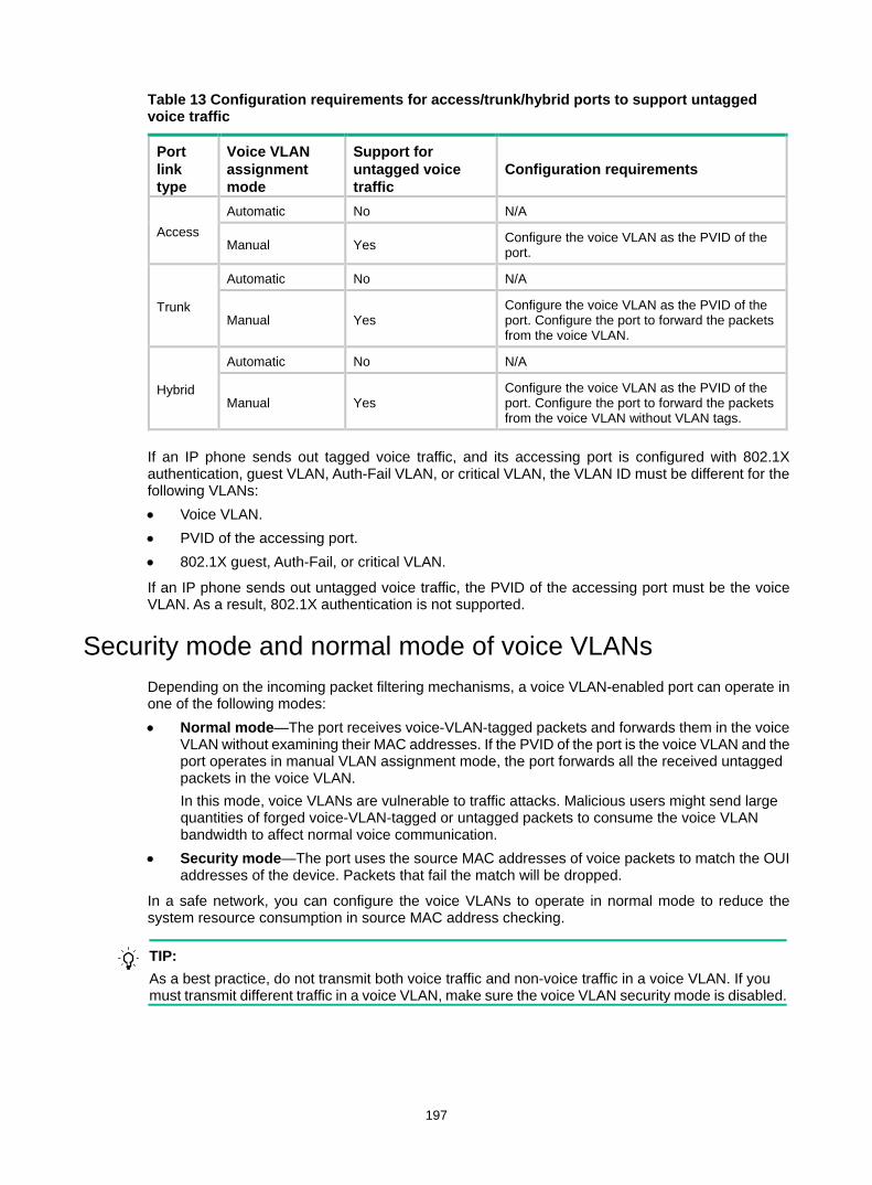
197
Table 13 Configuration requirements for access/trunk/hybrid ports to support untagged voice traffic
Port link type
Voice VLAN assignment mode
Support for untagged voice traffic
Configuration requirements
Access Automatic No N/A
Manual Yes Configure the voice VLAN as the PVID of the port.
Trunk
Automatic No N/A
Manual Yes Configure the voice VLAN as the PVID of the port. Configure the port to forward the packets from the voice VLAN.
Hybrid
Automatic No N/A
Manual Yes Configure the voice VLAN as the PVID of the port. Configure the port to forward the packets from the voice VLAN without VLAN tags.
If an IP phone sends out tagged voice traffic, and its accessing port is configured with 802.1X authentication, guest VLAN, Auth-Fail VLAN, or critical VLAN, the VLAN ID must be different for the following VLANs: • Voice VLAN. • PVID of the accessing port. • 802.1X guest, Auth-Fail, or critical VLAN.
If an IP phone sends out untagged voice traffic, the PVID of the accessing port must be the voice VLAN. As a result, 802.1X authentication is not supported.
Security mode and normal mode of voice VLANs Depending on the incoming packet filtering mechanisms, a voice VLAN-enabled port can operate in one of the following modes: • Normal mode—The port receives voice-VLAN-tagged packets and forwards them in the voice
VLAN without examining their MAC addresses. If the PVID of the port is the voice VLAN and the port operates in manual VLAN assignment mode, the port forwards all the received untagged packets in the voice VLAN. In this mode, voice VLANs are vulnerable to traffic attacks. Malicious users might send large quantities of forged voice-VLAN-tagged or untagged packets to consume the voice VLAN bandwidth to affect normal voice communication.
• Security mode—The port uses the source MAC addresses of voice packets to match the OUI addresses of the device. Packets that fail the match will be dropped.
In a safe network, you can configure the voice VLANs to operate in normal mode to reduce the system resource consumption in source MAC address checking.
TIP: As a best practice, do not transmit both voice traffic and non-voice traffic in a voice VLAN. If you must transmit different traffic in a voice VLAN, make sure the voice VLAN security mode is disabled.
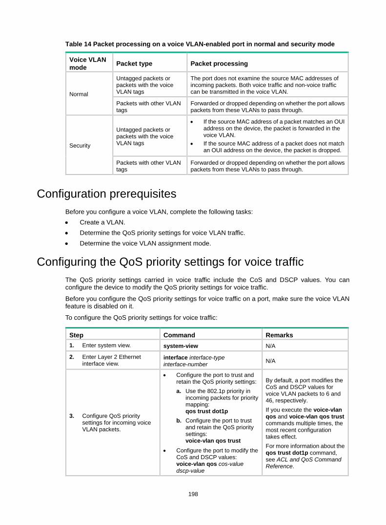
198
Table 14 Packet processing on a voice VLAN-enabled port in normal and security mode
Voice VLAN mode Packet type Packet processing
Normal
Untagged packets or packets with the voice VLAN tags
The port does not examine the source MAC addresses of incoming packets. Both voice traffic and non-voice traffic can be transmitted in the voice VLAN.
Packets with other VLAN tags
Forwarded or dropped depending on whether the port allows packets from these VLANs to pass through.
Security
Untagged packets or packets with the voice VLAN tags
• If the source MAC address of a packet matches an OUI address on the device, the packet is forwarded in the voice VLAN.
• If the source MAC address of a packet does not match an OUI address on the device, the packet is dropped.
Packets with other VLAN tags
Forwarded or dropped depending on whether the port allows packets from these VLANs to pass through.
Configuration prerequisites Before you configure a voice VLAN, complete the following tasks: • Create a VLAN. • Determine the QoS priority settings for voice VLAN traffic. • Determine the voice VLAN assignment mode.
Configuring the QoS priority settings for voice traffic The QoS priority settings carried in voice traffic include the CoS and DSCP values. You can configure the device to modify the QoS priority settings for voice traffic.
Before you configure the QoS priority settings for voice traffic on a port, make sure the voice VLAN feature is disabled on it.
To configure the QoS priority settings for voice traffic:
Step Command Remarks 1. Enter system view. system-view N/A
2. Enter Layer 2 Ethernet interface view.
interface interface-type interface-number N/A
3. Configure QoS priority settings for incoming voice VLAN packets.
• Configure the port to trust and retain the QoS priority settings: a. Use the 802.1p priority in
incoming packets for priority mapping: qos trust dot1p
b. Configure the port to trust and retain the QoS priority settings: voice-vlan qos trust
• Configure the port to modify the CoS and DSCP values: voice-vlan qos cos-value dscp-value
By default, a port modifies the CoS and DSCP values for voice VLAN packets to 6 and 46, respectively. If you execute the voice-vlan qos and voice-vlan qos trust commands multiple times, the most recent configuration takes effect. For more information about the qos trust dot1p command, see ACL and QoS Command Reference.

199
Configuring a port to operate in automatic voice VLAN assignment mode Configuration restrictions and guidelines
When you configure a port to operate in automatic voice VLAN assignment mode, follow these restrictions and guidelines: • Do not configure a VLAN as both a voice VLAN and a protocol-based VLAN. A voice VLAN in
automatic mode on a hybrid port processes only tagged incoming voice traffic. A protocol-based VLAN on a hybrid port processes only untagged incoming packets. For more information about protocol-based VLANs, see "Configuring protocol-based VLANs."
• As a best practice, do not use the automatic voice VLAN assignment mode together with MSTP. In MSTP mode, if a port is blocked in the MSTI of the target voice VLAN, the port drops the received packets instead of delivering them to the CPU. As a result, the receiving port will not be dynamically assigned to the voice VLAN.
• As a best practice, do not use the automatic voice VLAN assignment mode together with PVST. In PVST mode, if the target voice VLAN is not permitted on a port, the port is placed in blocked state. The received packets are dropped instead of being delivered to the CPU. As a result, the receiving port will not be dynamically assigned to the voice VLAN.
• As a best practice, do not configure both dynamic MAC-based VLAN assignment and automatic voice VLAN assignment mode on a port. If you have to configure both of them on a port, configure dynamic MAC-based VLAN assignment first. If you configure them in a reverse order, conflict will occur. When you remove one of the configurations, the operation of the other is affected.
Configuration procedure To configure a port to operate in automatic voice VLAN assignment mode:
Step Command Remarks 1. Enter system view. system-view N/A
2. (Optional.) Set the voice VLAN aging timer. voice-vlan aging minutes
By default, the aging timer of a voice VLAN is 1440 minutes. The voice VLAN aging timer takes effect only on ports in automatic voice VLAN assignment mode.
3. (Optional.) Enable the voice VLAN security mode. voice-vlan security enable By default, the voice VLAN
security mode is enabled.
4. (Optional.) Add an OUI address for voice packet identification.
voice-vlan mac-address oui mask oui-mask [ description text ]
By default, system default OUI addresses exist. For more information, see Table 11.
5. Enter Layer 2 Ethernet interface view.
interface interface-type interface-number N/A
6. Configure the link type of the port.
• port link-type trunk • port link-type hybrid N/A
7. (Optional.) Configure the port to operate in automatic voice VLAN assignment mode.
voice-vlan mode auto By default, the automatic voice VLAN assignment mode is enabled.
8. Enable the voice VLAN feature on the port. voice-vlan vlan-id enable By default, the voice VLAN
feature is disabled.
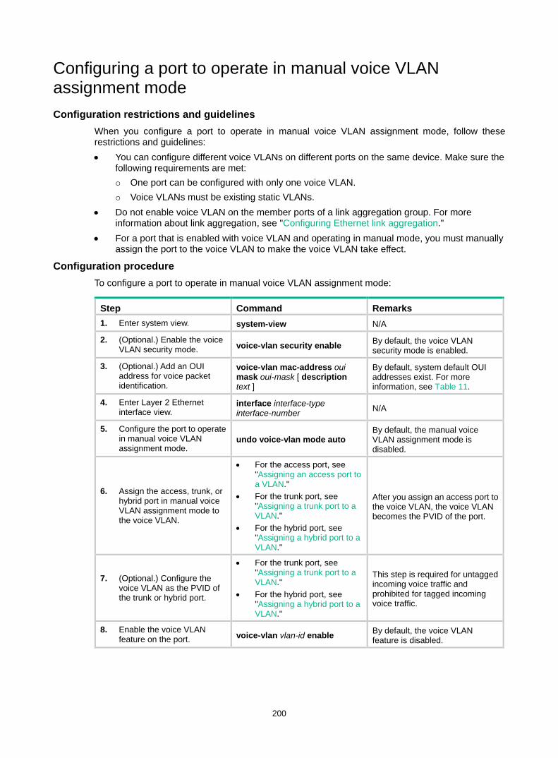
200
Configuring a port to operate in manual voice VLAN assignment mode Configuration restrictions and guidelines
When you configure a port to operate in manual voice VLAN assignment mode, follow these restrictions and guidelines: • You can configure different voice VLANs on different ports on the same device. Make sure the
following requirements are met: One port can be configured with only one voice VLAN. Voice VLANs must be existing static VLANs.
• Do not enable voice VLAN on the member ports of a link aggregation group. For more information about link aggregation, see "Configuring Ethernet link aggregation."
• For a port that is enabled with voice VLAN and operating in manual mode, you must manually assign the port to the voice VLAN to make the voice VLAN take effect.
Configuration procedure To configure a port to operate in manual voice VLAN assignment mode:
Step Command Remarks 1. Enter system view. system-view N/A
2. (Optional.) Enable the voice VLAN security mode. voice-vlan security enable By default, the voice VLAN
security mode is enabled.
3. (Optional.) Add an OUI address for voice packet identification.
voice-vlan mac-address oui mask oui-mask [ description text ]
By default, system default OUI addresses exist. For more information, see Table 11.
4. Enter Layer 2 Ethernet interface view.
interface interface-type interface-number N/A
5. Configure the port to operate in manual voice VLAN assignment mode.
undo voice-vlan mode auto By default, the manual voice VLAN assignment mode is disabled.
6. Assign the access, trunk, or hybrid port in manual voice VLAN assignment mode to the voice VLAN.
• For the access port, see "Assigning an access port to a VLAN."
• For the trunk port, see "Assigning a trunk port to a VLAN."
• For the hybrid port, see "Assigning a hybrid port to a VLAN."
After you assign an access port to the voice VLAN, the voice VLAN becomes the PVID of the port.
7. (Optional.) Configure the voice VLAN as the PVID of the trunk or hybrid port.
• For the trunk port, see "Assigning a trunk port to a VLAN."
• For the hybrid port, see "Assigning a hybrid port to a VLAN."
This step is required for untagged incoming voice traffic and prohibited for tagged incoming voice traffic.
8. Enable the voice VLAN feature on the port. voice-vlan vlan-id enable By default, the voice VLAN
feature is disabled.
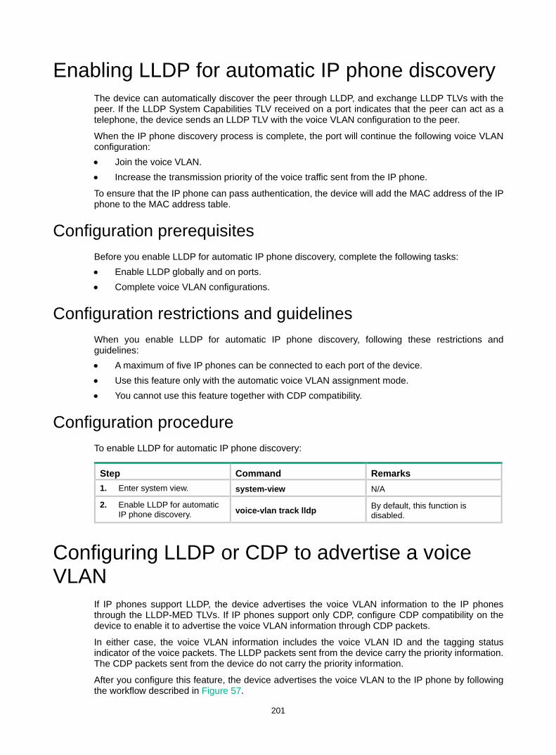
201
Enabling LLDP for automatic IP phone discovery The device can automatically discover the peer through LLDP, and exchange LLDP TLVs with the peer. If the LLDP System Capabilities TLV received on a port indicates that the peer can act as a telephone, the device sends an LLDP TLV with the voice VLAN configuration to the peer.
When the IP phone discovery process is complete, the port will continue the following voice VLAN configuration: • Join the voice VLAN. • Increase the transmission priority of the voice traffic sent from the IP phone.
To ensure that the IP phone can pass authentication, the device will add the MAC address of the IP phone to the MAC address table.
Configuration prerequisites Before you enable LLDP for automatic IP phone discovery, complete the following tasks: • Enable LLDP globally and on ports. • Complete voice VLAN configurations.
Configuration restrictions and guidelines When you enable LLDP for automatic IP phone discovery, following these restrictions and guidelines: • A maximum of five IP phones can be connected to each port of the device. • Use this feature only with the automatic voice VLAN assignment mode. • You cannot use this feature together with CDP compatibility.
Configuration procedure To enable LLDP for automatic IP phone discovery:
Step Command Remarks 1. Enter system view. system-view N/A
2. Enable LLDP for automatic IP phone discovery. voice-vlan track lldp By default, this function is
disabled.
Configuring LLDP or CDP to advertise a voice VLAN
If IP phones support LLDP, the device advertises the voice VLAN information to the IP phones through the LLDP-MED TLVs. If IP phones support only CDP, configure CDP compatibility on the device to enable it to advertise the voice VLAN information through CDP packets.
In either case, the voice VLAN information includes the voice VLAN ID and the tagging status indicator of the voice packets. The LLDP packets sent from the device carry the priority information. The CDP packets sent from the device do not carry the priority information.
After you configure this feature, the device advertises the voice VLAN to the IP phone by following the workflow described in Figure 57.
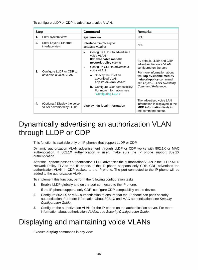
202
To configure LLDP or CDP to advertise a voice VLAN:
Step Command Remarks 1. Enter system view. system-view N/A
2. Enter Layer 2 Ethernet interface view.
interface interface-type interface-number N/A
3. Configure LLDP or CDP to advertise a voice VLAN.
• Configure LLDP to advertise a voice VLAN: lldp tlv-enable med-tlv network-policy vlan-id
• Configure CDP to advertise a voice VLAN: a. Specify the ID of an
advertised VLAN: cdp voice-vlan vlan-id
b. Configure CDP compatibility: For more information, see "Configuring LLDP."
By default, LLDP and CDP advertise the voice VLAN configured on the port. For more information about the lldp tlv-enable med-tlv network-policy command, see Layer 2—LAN Switching Command Reference.
4. (Optional.) Display the voice VLAN advertised by LLDP. display lldp local-information
The advertised voice LAN information is displayed in the MED information fields in the command output.
Dynamically advertising an authorization VLAN through LLDP or CDP
This function is available only on IP phones that support LLDP or CDP.
Dynamic authorization VLAN advertisement through LLDP or CDP works with 802.1X or MAC authentication. If 802.1X authentication is used, make sure the IP phone support 802.1X authentication.
After the IP phone passes authentication, LLDP advertises the authorization VLAN in the LLDP-MED Network Policy TLV to the IP phone. If the IP phone supports only CDP, CDP advertises the authorization VLAN in CDP packets to the IP phone. The port connected to the IP phone will be added to the authorization VLAN.
To implement this function, perform the following configuration tasks: 1. Enable LLDP globally and on the port connected to the IP phone.
If the IP phone supports only CDP, configure CDP compatibility on the device. 2. Configure 802.1X or MAC authentication to ensure that the IP phone can pass security
authentication. For more information about 802.1X and MAC authentication, see Security Configuration Guide.
3. Configure the authorization VLAN for the IP phone on the authentication server. For more information about authorization VLANs, see Security Configuration Guide.
Displaying and maintaining voice VLANs Execute display commands in any view.
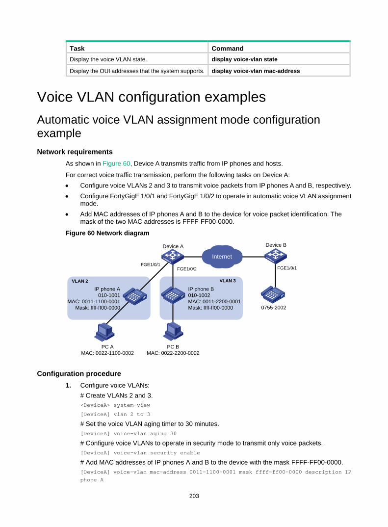
203
Task Command Display the voice VLAN state. display voice-vlan state
Display the OUI addresses that the system supports. display voice-vlan mac-address
Voice VLAN configuration examples Automatic voice VLAN assignment mode configuration example Network requirements
As shown in Figure 60, Device A transmits traffic from IP phones and hosts.
For correct voice traffic transmission, perform the following tasks on Device A: • Configure voice VLANs 2 and 3 to transmit voice packets from IP phones A and B, respectively. • Configure FortyGigE 1/0/1 and FortyGigE 1/0/2 to operate in automatic voice VLAN assignment
mode. • Add MAC addresses of IP phones A and B to the device for voice packet identification. The
mask of the two MAC addresses is FFFF-FF00-0000.
Figure 60 Network diagram
Configuration procedure 1. Configure voice VLANs:
# Create VLANs 2 and 3. <DeviceA> system-view
[DeviceA] vlan 2 to 3
# Set the voice VLAN aging timer to 30 minutes. [DeviceA] voice-vlan aging 30
# Configure voice VLANs to operate in security mode to transmit only voice packets. [DeviceA] voice-vlan security enable
# Add MAC addresses of IP phones A and B to the device with the mask FFFF-FF00-0000. [DeviceA] voice-vlan mac-address 0011-1100-0001 mask ffff-ff00-0000 description IP phone A
Device A Device B
FGE1/0/1FGE1/0/1
IP phone B010-1002MAC: 0011-2200-0001Mask: ffff-ff00-0000 0755-2002
FGE1/0/2
IP phone A010-1001
MAC: 0011-1100-0001Mask: ffff-ff00-0000
Internet
PC AMAC: 0022-1100-0002
PC BMAC: 0022-2200-0002
VLAN 3VLAN 2

204
[DeviceA] voice-vlan mac-address 0011-2200-0001 mask ffff-ff00-0000 description IP phone B
2. Configure FortyGigE 1/0/1: # Configure FortyGigE 1/0/1 as a hybrid port. [DeviceA] interface fortygige 1/0/1
[DeviceA-FortyGigE1/0/1] port link-type hybrid
# Configure FortyGigE 1/0/1 to operate in automatic voice VLAN assignment mode. [DeviceA-FortyGigE1/0/1] voice-vlan mode auto
# Enable voice VLAN on FortyGigE 1/0/1 and configure VLAN 2 as the voice VLAN for it. [DeviceA-FortyGigE1/0/1] voice-vlan 2 enable
[DeviceA-FortyGigE1/0/1] quit
3. Configure FortyGigE 1/0/2: # Configure FortyGigE 1/0/2 as a hybrid port. [DeviceA] interface fortygige 1/0/2
[DeviceA-FortyGigE1/0/2] port link-type hybrid
# Configure FortyGigE 1/0/2 to operate in automatic voice VLAN assignment mode. [DeviceA-FortyGigE1/0/2] voice-vlan mode auto
# Enable voice VLAN on FortyGigE 1/0/2 and configure VLAN 3 as the voice VLAN for it. [DeviceA-FortyGigE1/0/2] voice-vlan 3 enable
[DeviceA-FortyGigE1/0/2] quit
Verifying the configuration # Display the OUI addresses and their masks and descriptions. [DeviceA] display voice-vlan mac-address
OUI Address Mask Description
0001-e300-0000 ffff-ff00-0000 Siemens phone
0003-6b00-0000 ffff-ff00-0000 Cisco phone
0004-0d00-0000 ffff-ff00-0000 Avaya phone
000f-e200-0000 ffff-ff00-0000 H3C Aolynk phone
0060-b900-0000 ffff-ff00-0000 Philips/NEC phone
00d0-1e00-0000 ffff-ff00-0000 Pingtel phone
00e0-7500-0000 ffff-ff00-0000 Polycom phone
00e0-bb00-0000 ffff-ff00-0000 3Com phone
# Display the voice VLAN state. [DeviceA] display voice-vlan state
Current Voice VLANs: 2
Voice VLAN security mode: Security
Voice VLAN aging time: 30 minutes
Voice VLAN enabled ports and their modes:
Port VLAN Mode COS DSCP
FGE1/0/1 2 AUTO 6 46
FGE1/0/2 3 AUTO 6 46
Manual voice VLAN assignment mode configuration example Network requirements
As shown in Figure 61:

205
• Device A transmits only voice traffic. • IP phone A send untagged voice traffic.
For correct voice traffic transmission, perform the following tasks on Device A: • Configure a voice VLAN to transmit voice traffic. • Configure FortyGigE 1/0/1 to operate in manual voice VLAN assignment mode. • Add the MAC address of IP phone A to the device for voice packet identification. The mask is
FFFF-FF00-0000.
Figure 61 Network diagram
Configuration procedure # Configure the voice VLAN to operate in security mode. <DeviceA> system-view
[DeviceA] voice-vlan security enable
# Add a MAC address 0011-2200-0000 with the mask FFFF-FF00-0000. [DeviceA] voice-vlan mac-address 0011-2200-0000 mask ffff-ff00-0000 description test
# Create VLAN 2. [DeviceA] vlan 2
[DeviceA-vlan2] quit
# Configure FortyGigE 1/0/1 to operate in manual voice VLAN assignment mode. [DeviceA] interface fortygige 1/0/1
[DeviceA-FortyGigE1/0/1] undo voice-vlan mode auto
# Configure FortyGigE 1/0/1 as a hybrid port. [DeviceA-FortyGigE1/0/1] port link-type hybrid
# Configure VLAN 2 as the PVID of FortyGigE 1/0/1. [DeviceA-FortyGigE1/0/1] port hybrid pvid vlan 2
# Configure FortyGigE 1/0/1 to forward the voice traffic from VLAN 2 without VLAN tags. [DeviceA-FortyGigE1/0/1] port hybrid vlan 2 untagged
# Enable voice VLAN and configure VLAN 2 as the voice VLAN on FortyGigE 1/0/1. [DeviceA-FortyGigE1/0/1] voice-vlan 2 enable
[DeviceA-FortyGigE1/0/1] quit
Verifying the configuration # Display the OUI addresses and their masks and descriptions. [DeviceA] display voice-vlan mac-address
OUI Address Mask Description
0001-e300-0000 ffff-ff00-0000 Siemens phone
Device A Device B
FGE1/0/1VLAN 2
IP phone A010-1001OUI: 0011-2200-0000Mask: ffff-ff00-0000
IP phone B0755-2002
Internet
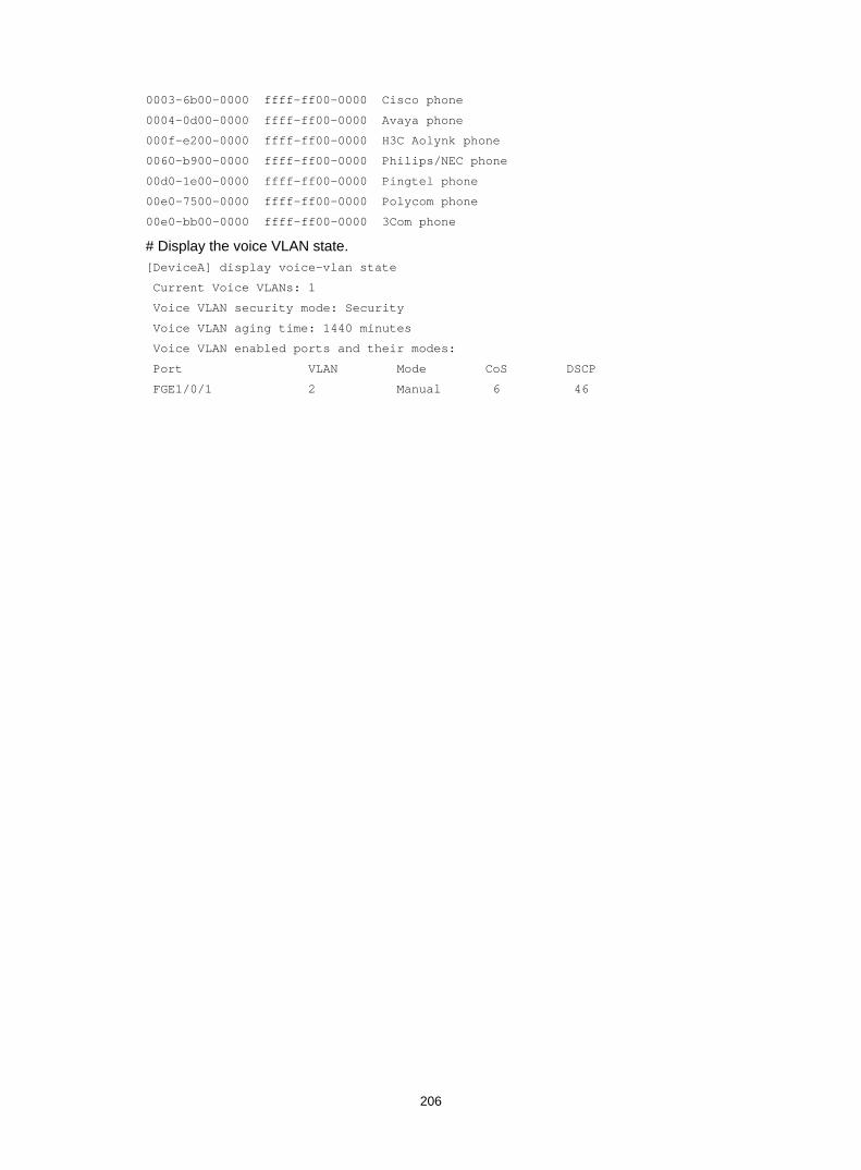
206
0003-6b00-0000 ffff-ff00-0000 Cisco phone
0004-0d00-0000 ffff-ff00-0000 Avaya phone
000f-e200-0000 ffff-ff00-0000 H3C Aolynk phone
0060-b900-0000 ffff-ff00-0000 Philips/NEC phone
00d0-1e00-0000 ffff-ff00-0000 Pingtel phone
00e0-7500-0000 ffff-ff00-0000 Polycom phone
00e0-bb00-0000 ffff-ff00-0000 3Com phone
# Display the voice VLAN state. [DeviceA] display voice-vlan state
Current Voice VLANs: 1
Voice VLAN security mode: Security
Voice VLAN aging time: 1440 minutes
Voice VLAN enabled ports and their modes:
Port VLAN Mode CoS DSCP
FGE1/0/1 2 Manual 6 46
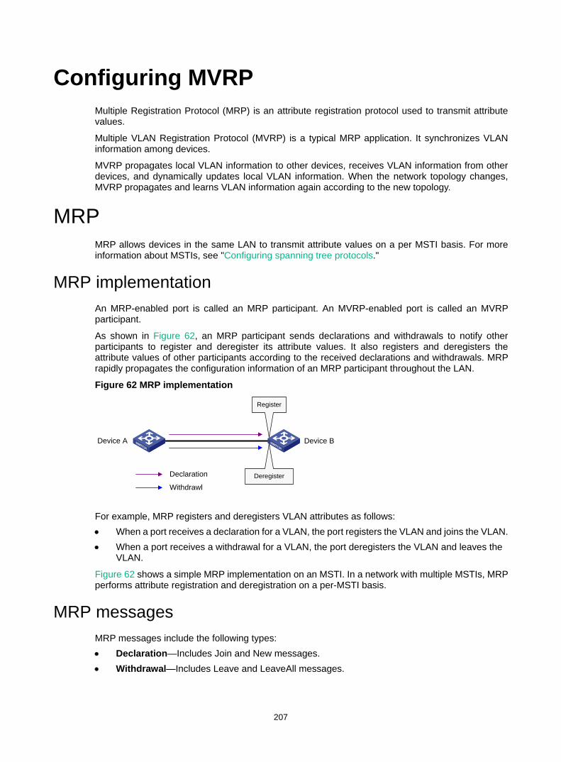
207
Configuring MVRP Multiple Registration Protocol (MRP) is an attribute registration protocol used to transmit attribute values.
Multiple VLAN Registration Protocol (MVRP) is a typical MRP application. It synchronizes VLAN information among devices.
MVRP propagates local VLAN information to other devices, receives VLAN information from other devices, and dynamically updates local VLAN information. When the network topology changes, MVRP propagates and learns VLAN information again according to the new topology.
MRP MRP allows devices in the same LAN to transmit attribute values on a per MSTI basis. For more information about MSTIs, see "Configuring spanning tree protocols."
MRP implementation An MRP-enabled port is called an MRP participant. An MVRP-enabled port is called an MVRP participant.
As shown in Figure 62, an MRP participant sends declarations and withdrawals to notify other participants to register and deregister its attribute values. It also registers and deregisters the attribute values of other participants according to the received declarations and withdrawals. MRP rapidly propagates the configuration information of an MRP participant throughout the LAN.
Figure 62 MRP implementation
For example, MRP registers and deregisters VLAN attributes as follows: • When a port receives a declaration for a VLAN, the port registers the VLAN and joins the VLAN. • When a port receives a withdrawal for a VLAN, the port deregisters the VLAN and leaves the
VLAN.
Figure 62 shows a simple MRP implementation on an MSTI. In a network with multiple MSTIs, MRP performs attribute registration and deregistration on a per-MSTI basis.
MRP messages MRP messages include the following types: • Declaration—Includes Join and New messages. • Withdrawal—Includes Leave and LeaveAll messages.
Device A Device B
Declaration Deregister
Register
Withdrawl
208
Join message An MRP participant sends a Join message to request the peer participant to register attributes in the Join message.
When receiving a Join message from the peer participant, an MRP participant performs the following tasks: • Registers the attributes in the Join message. • Propagates the Join message to all other participants on the device.
After receiving the Join message, other participants send the Join message to their respective peer participants.
Join messages sent from a local participant to its peer participant include the following types: • JoinEmpty—Declares an unregistered attribute. For example, when an MRP participant joins
an unregistered static VLAN, it sends a JoinEmpty message. VLANs created manually and locally are called static VLANs. VLANs learned through MRP are called dynamic VLANs.
• JoinIn—Declares a registered attribute. A JoinIn message is used in one of the following situations: An MRP participant joins an existing static VLAN and sends a JoinIn message after
registering the VLAN. The MRP participant receives a Join message propagated by another participant on the
device and sends a JoinIn message after registering the VLAN.
New message Similar to a Join message, a New message enables MRP participants to register attributes.
When the MSTP topology changes, an MRP participant sends a New message to the peer participant to declare the topology change.
Upon receiving a New message from the peer participant, an MRP participant performs the following tasks: • Registers the attributes in the message. • Propagates the New message to all other participants on the device.
After receiving the New message, other participants send the New message to their respective peer participants.
Leave message An MRP participant sends a Leave message to the peer participant when it wants the peer participant to deregister attributes that it has deregistered.
When the peer participant receives the Leave message, it performs the following tasks: • Deregisters the attribute in the Leave message. • Propagates the Leave message to all other participants on the device.
After a participant on the device receives the Leave message, it determines whether to send the Leave message to its peer participant depending on the attribute status on the device. • If the VLAN in the Leave message is a dynamic VLAN not registered by any participants on the
device, both of the following events occur: The VLAN is deleted on the device. The participant sends the Leave message to its peer participant.
• If the VLAN in the a Leave message is a static VLAN, the participant will not send the Leave message to its peer participant.
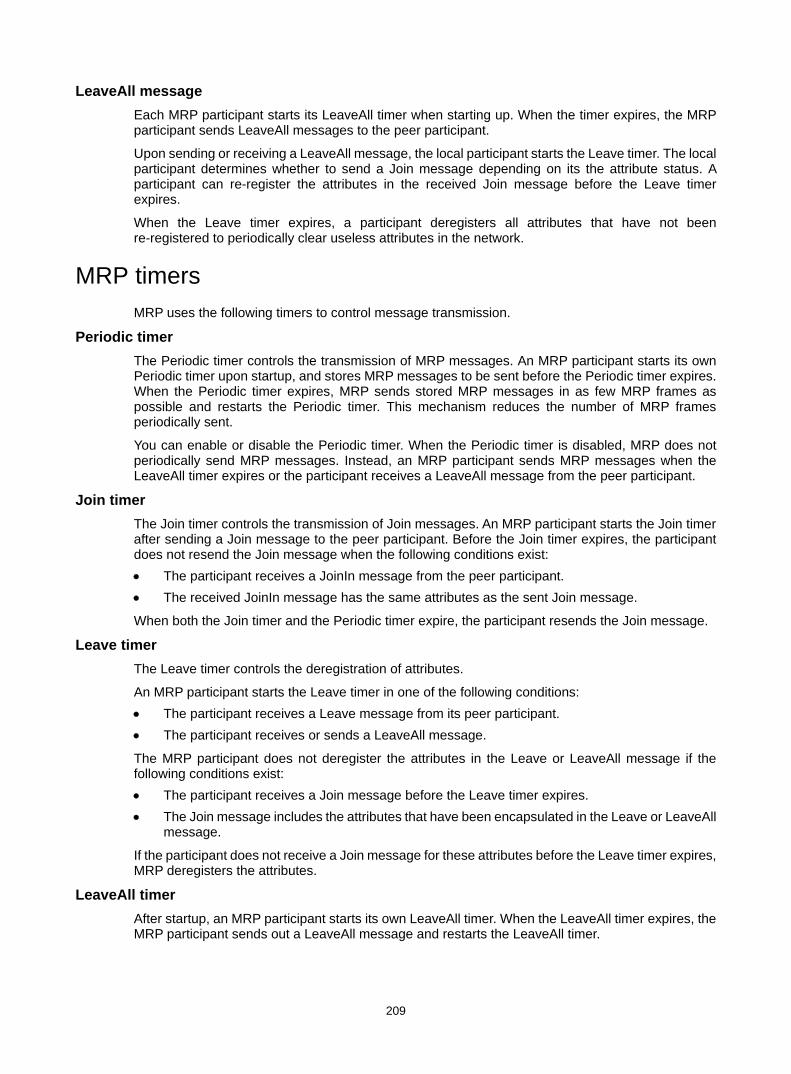
209
LeaveAll message Each MRP participant starts its LeaveAll timer when starting up. When the timer expires, the MRP participant sends LeaveAll messages to the peer participant.
Upon sending or receiving a LeaveAll message, the local participant starts the Leave timer. The local participant determines whether to send a Join message depending on its the attribute status. A participant can re-register the attributes in the received Join message before the Leave timer expires.
When the Leave timer expires, a participant deregisters all attributes that have not been re-registered to periodically clear useless attributes in the network.
MRP timers MRP uses the following timers to control message transmission.
Periodic timer The Periodic timer controls the transmission of MRP messages. An MRP participant starts its own Periodic timer upon startup, and stores MRP messages to be sent before the Periodic timer expires. When the Periodic timer expires, MRP sends stored MRP messages in as few MRP frames as possible and restarts the Periodic timer. This mechanism reduces the number of MRP frames periodically sent.
You can enable or disable the Periodic timer. When the Periodic timer is disabled, MRP does not periodically send MRP messages. Instead, an MRP participant sends MRP messages when the LeaveAll timer expires or the participant receives a LeaveAll message from the peer participant.
Join timer The Join timer controls the transmission of Join messages. An MRP participant starts the Join timer after sending a Join message to the peer participant. Before the Join timer expires, the participant does not resend the Join message when the following conditions exist: • The participant receives a JoinIn message from the peer participant. • The received JoinIn message has the same attributes as the sent Join message.
When both the Join timer and the Periodic timer expire, the participant resends the Join message.
Leave timer The Leave timer controls the deregistration of attributes.
An MRP participant starts the Leave timer in one of the following conditions: • The participant receives a Leave message from its peer participant. • The participant receives or sends a LeaveAll message.
The MRP participant does not deregister the attributes in the Leave or LeaveAll message if the following conditions exist: • The participant receives a Join message before the Leave timer expires. • The Join message includes the attributes that have been encapsulated in the Leave or LeaveAll
message.
If the participant does not receive a Join message for these attributes before the Leave timer expires, MRP deregisters the attributes.
LeaveAll timer After startup, an MRP participant starts its own LeaveAll timer. When the LeaveAll timer expires, the MRP participant sends out a LeaveAll message and restarts the LeaveAll timer.
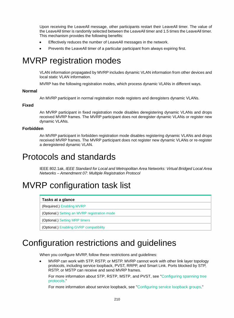
210
Upon receiving the LeaveAll message, other participants restart their LeaveAll timer. The value of the LeaveAll timer is randomly selected between the LeaveAll timer and 1.5 times the LeaveAll timer. This mechanism provides the following benefits: • Effectively reduces the number of LeaveAll messages in the network. • Prevents the LeaveAll timer of a particular participant from always expiring first.
MVRP registration modes VLAN information propagated by MVRP includes dynamic VLAN information from other devices and local static VLAN information.
MVRP has the following registration modes, which process dynamic VLANs in different ways.
Normal An MVRP participant in normal registration mode registers and deregisters dynamic VLANs.
Fixed An MVRP participant in fixed registration mode disables deregistering dynamic VLANs and drops received MVRP frames. The MVRP participant does not deregister dynamic VLANs or register new dynamic VLANs.
Forbidden An MVRP participant in forbidden registration mode disables registering dynamic VLANs and drops received MVRP frames. The MVRP participant does not register new dynamic VLANs or re-register a deregistered dynamic VLAN.
Protocols and standards IEEE 802.1ak, IEEE Standard for Local and Metropolitan Area Networks: Virtual Bridged Local Area Networks – Amendment 07: Multiple Registration Protocol
MVRP configuration task list Tasks at a glance (Required.) Enabling MVRP
(Optional.) Setting an MVRP registration mode
(Optional.) Setting MRP timers
(Optional.) Enabling GVRP compatibility
Configuration restrictions and guidelines When you configure MVRP, follow these restrictions and guidelines: • MVRP can work with STP, RSTP, or MSTP. MVRP cannot work with other link layer topology
protocols, including service loopback, PVST, RRPP, and Smart Link. Ports blocked by STP, RSTP, or MSTP can receive and send MVRP frames. For more information about STP, RSTP, MSTP, and PVST, see "Configuring spanning tree protocols." For more information about service loopback, see "Configuring service loopback groups."

211
For more information about RRPP and Smart Link, see High Availability Configuration Guide. • Do not configure both MVRP and remote port mirroring on a port. Otherwise, MVRP might
register the remote probe VLAN with incorrect ports, which would cause the monitor port to receive undesired copies. For more information about port mirroring, see Network Management and Monitoring Configuration Guide.
• MVRP takes effect only on trunk ports. For more information about trunk ports, see "Configuring VLANs."
• Enabling MVRP on a Layer 2 aggregate interface takes effect on the aggregate interface and all Selected member ports in the link aggregation group.
• MVRP configuration made on an aggregation group member port takes effect only after the port is removed from the aggregation group.
Configuration prerequisites Before configuring MVRP, make sure each MSTI is mapped to an existing VLAN on each device in the network.
Enabling MVRP Step Command Remarks 1. Enter system view. system-view N/A
2. Enable MVRP globally. mvrp global enable
By default, MVRP is globally disabled. To make MVRP take effect on a port, enable MVRP both on the port and globally.
3. Enter Layer 2 Ethernet interface view or Layer 2 aggregate interface view.
interface interface-type interface-number N/A
4. Configure the port as a trunk port. port link-type trunk
By default, any port is an access port. For more information about the port link-type trunk command, see Layer 2—LAN Switching Command Reference.
5. Configure the trunk port to permit the specified VLANs.
port trunk permit vlan { vlan-id-list | all }
By default, a trunk port permits only VLAN 1. Make sure the trunk port permits all registered VLANs. For more information about the port trunk permit vlan command, see Layer 2—LAN Switching Command Reference.
6. Enable MVRP on the port. mvrp enable By default, MVRP is disabled on a port.
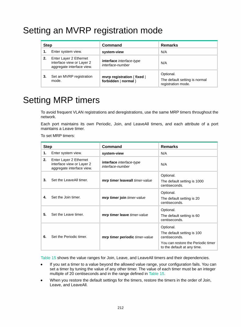
212
Setting an MVRP registration mode Step Command Remarks 1. Enter system view. system-view N/A
2. Enter Layer 2 Ethernet interface view or Layer 2 aggregate interface view.
interface interface-type interface-number N/A
3. Set an MVRP registration mode.
mvrp registration { fixed | forbidden | normal }
Optional. The default setting is normal registration mode.
Setting MRP timers To avoid frequent VLAN registrations and deregistrations, use the same MRP timers throughout the network.
Each port maintains its own Periodic, Join, and LeaveAll timers, and each attribute of a port maintains a Leave timer.
To set MRP timers:
Step Command Remarks 1. Enter system view. system-view N/A
2. Enter Layer 2 Ethernet interface view or Layer 2 aggregate interface view.
interface interface-type interface-number N/A
3. Set the LeaveAll timer. mrp timer leaveall timer-value Optional. The default setting is 1000 centiseconds.
4. Set the Join timer. mrp timer join timer-value Optional. The default setting is 20 centiseconds.
5. Set the Leave timer. mrp timer leave timer-value Optional. The default setting is 60 centiseconds.
6. Set the Periodic timer. mrp timer periodic timer-value
Optional. The default setting is 100 centiseconds. You can restore the Periodic timer to the default at any time.
Table 15 shows the value ranges for Join, Leave, and LeaveAll timers and their dependencies. • If you set a timer to a value beyond the allowed value range, your configuration fails. You can
set a timer by tuning the value of any other timer. The value of each timer must be an integer multiple of 20 centiseconds and in the range defined in Table 15.
• When you restore the default settings for the timers, restore the timers in the order of Join, Leave, and LeaveAll.
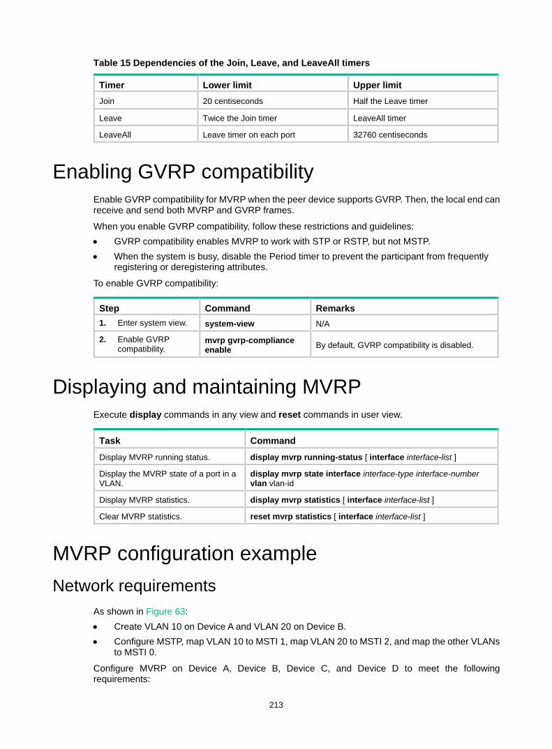
213
Table 15 Dependencies of the Join, Leave, and LeaveAll timers
Timer Lower limit Upper limit Join 20 centiseconds Half the Leave timer
Leave Twice the Join timer LeaveAll timer
LeaveAll Leave timer on each port 32760 centiseconds
Enabling GVRP compatibility Enable GVRP compatibility for MVRP when the peer device supports GVRP. Then, the local end can receive and send both MVRP and GVRP frames.
When you enable GVRP compatibility, follow these restrictions and guidelines: • GVRP compatibility enables MVRP to work with STP or RSTP, but not MSTP. • When the system is busy, disable the Period timer to prevent the participant from frequently
registering or deregistering attributes.
To enable GVRP compatibility:
Step Command Remarks 1. Enter system view. system-view N/A
2. Enable GVRP compatibility.
mvrp gvrp-compliance enable By default, GVRP compatibility is disabled.
Displaying and maintaining MVRP Execute display commands in any view and reset commands in user view.
Task Command Display MVRP running status. display mvrp running-status [ interface interface-list ]
Display the MVRP state of a port in a VLAN.
display mvrp state interface interface-type interface-number vlan vlan-id
Display MVRP statistics. display mvrp statistics [ interface interface-list ]
Clear MVRP statistics. reset mvrp statistics [ interface interface-list ]
MVRP configuration example Network requirements
As shown in Figure 63: • Create VLAN 10 on Device A and VLAN 20 on Device B. • Configure MSTP, map VLAN 10 to MSTI 1, map VLAN 20 to MSTI 2, and map the other VLANs
to MSTI 0.
Configure MVRP on Device A, Device B, Device C, and Device D to meet the following requirements:
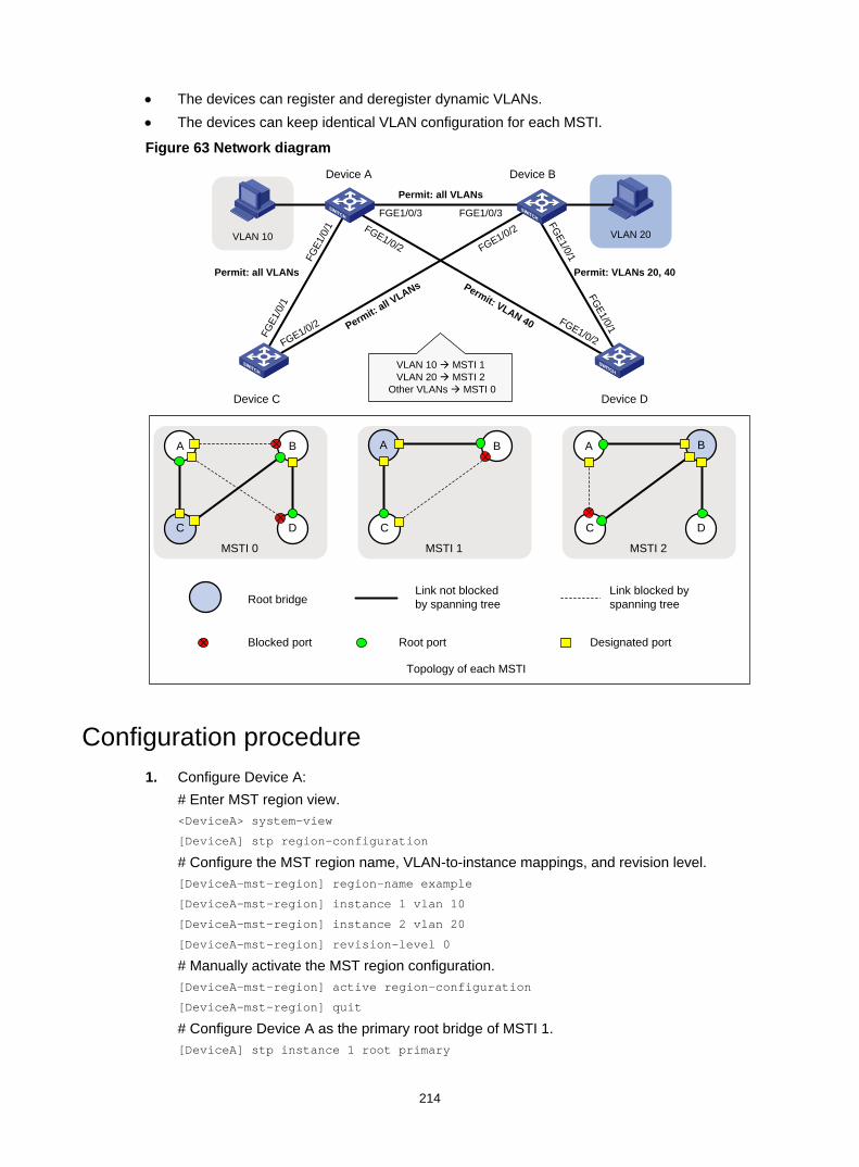
214
• The devices can register and deregister dynamic VLANs. • The devices can keep identical VLAN configuration for each MSTI.
Figure 63 Network diagram
Configuration procedure 1. Configure Device A:
# Enter MST region view. <DeviceA> system-view
[DeviceA] stp region-configuration
# Configure the MST region name, VLAN-to-instance mappings, and revision level. [DeviceA-mst-region] region-name example
[DeviceA-mst-region] instance 1 vlan 10
[DeviceA-mst-region] instance 2 vlan 20
[DeviceA-mst-region] revision-level 0
# Manually activate the MST region configuration. [DeviceA-mst-region] active region-configuration
[DeviceA-mst-region] quit
# Configure Device A as the primary root bridge of MSTI 1. [DeviceA] stp instance 1 root primary
VLAN 20
Permit: all VLANs
Permit: VLAN 40Permit: all V
LANsPermit: VLANs 20, 40Permit: all VLANs
Device A Device B
Device C Device D
FGE1/0/2
FGE1
/0/1
FGE1/0/2
FGE1/0/1
FGE1
/0/1
FGE1/0/1
FGE1/0/3 FGE1/0/3FGE1/0/2 FGE1/0/2
VLAN 10 à MSTI 1VLAN 20 à MSTI 2
Other VLANs à MSTI 0
VLAN 10
MSTI 2
A
D
Blocked port
Root bridge
MSTI 1
B
MSTI 0
A
C
B
D
A
C
B
C
Topology of each MSTI
Root port Designated port
Link not blocked by spanning tree
Link blocked by spanning tree
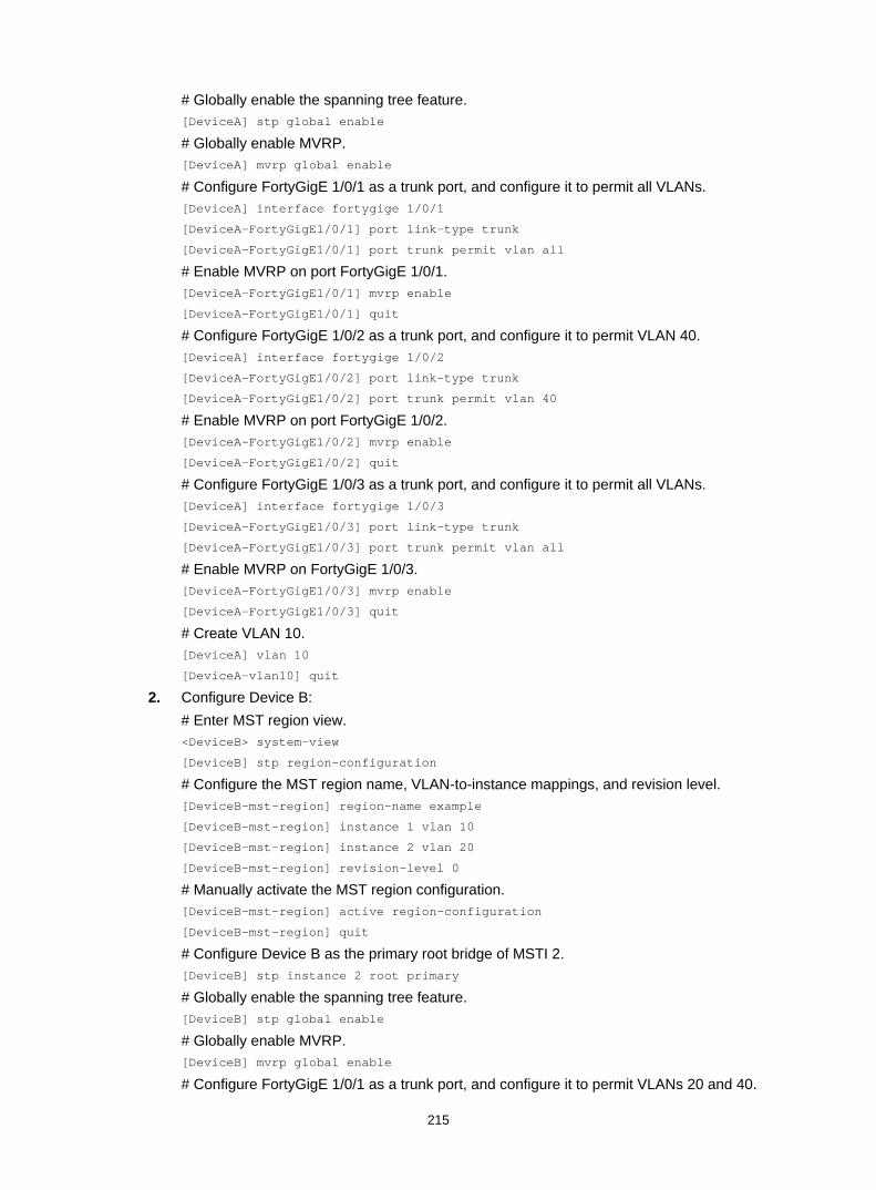
215
# Globally enable the spanning tree feature. [DeviceA] stp global enable
# Globally enable MVRP. [DeviceA] mvrp global enable
# Configure FortyGigE 1/0/1 as a trunk port, and configure it to permit all VLANs. [DeviceA] interface fortygige 1/0/1
[DeviceA-FortyGigE1/0/1] port link-type trunk
[DeviceA-FortyGigE1/0/1] port trunk permit vlan all
# Enable MVRP on port FortyGigE 1/0/1. [DeviceA-FortyGigE1/0/1] mvrp enable
[DeviceA-FortyGigE1/0/1] quit
# Configure FortyGigE 1/0/2 as a trunk port, and configure it to permit VLAN 40. [DeviceA] interface fortygige 1/0/2
[DeviceA-FortyGigE1/0/2] port link-type trunk
[DeviceA-FortyGigE1/0/2] port trunk permit vlan 40
# Enable MVRP on port FortyGigE 1/0/2. [DeviceA-FortyGigE1/0/2] mvrp enable
[DeviceA-FortyGigE1/0/2] quit
# Configure FortyGigE 1/0/3 as a trunk port, and configure it to permit all VLANs. [DeviceA] interface fortygige 1/0/3
[DeviceA-FortyGigE1/0/3] port link-type trunk
[DeviceA-FortyGigE1/0/3] port trunk permit vlan all
# Enable MVRP on FortyGigE 1/0/3. [DeviceA-FortyGigE1/0/3] mvrp enable
[DeviceA-FortyGigE1/0/3] quit
# Create VLAN 10. [DeviceA] vlan 10
[DeviceA-vlan10] quit
2. Configure Device B: # Enter MST region view. <DeviceB> system-view
[DeviceB] stp region-configuration
# Configure the MST region name, VLAN-to-instance mappings, and revision level. [DeviceB-mst-region] region-name example
[DeviceB-mst-region] instance 1 vlan 10
[DeviceB-mst-region] instance 2 vlan 20
[DeviceB-mst-region] revision-level 0
# Manually activate the MST region configuration. [DeviceB-mst-region] active region-configuration
[DeviceB-mst-region] quit
# Configure Device B as the primary root bridge of MSTI 2. [DeviceB] stp instance 2 root primary
# Globally enable the spanning tree feature. [DeviceB] stp global enable
# Globally enable MVRP. [DeviceB] mvrp global enable
# Configure FortyGigE 1/0/1 as a trunk port, and configure it to permit VLANs 20 and 40.

216
[DeviceB] interface fortygige 1/0/1
[DeviceB-FortyGigE1/0/1] port link-type trunk
[DeviceB-FortyGigE1/0/1] port trunk permit vlan 20 40
# Enable MVRP on FortyGigE 1/0/1. [DeviceB-FortyGigE1/0/1] mvrp enable
[DeviceB-FortyGigE1/0/1] quit
# Configure FortyGigE 1/0/2 as a trunk port, and configure it to permit all VLANs. [DeviceB] interface fortygige 1/0/2
[DeviceB-FortyGigE1/0/2] port link-type trunk
[DeviceB-FortyGigE1/0/2] port trunk permit vlan all
# Enable MVRP on FortyGigE 1/0/2. [DeviceB-FortyGigE1/0/2] mvrp enable
[DeviceB-FortyGigE1/0/2] quit
# Configure FortyGigE 1/0/3 as a trunk port, and configure it to permit all VLANs. [DeviceB] interface fortygige 1/0/3
[DeviceB-FortyGigE1/0/3] port link-type trunk
[DeviceB-FortyGigE1/0/3] port trunk permit vlan all
# Enable MVRP on FortyGigE 1/0/3. [DeviceB-FortyGigE1/0/3] mvrp enable
[DeviceB-FortyGigE1/0/3] quit
# Create VLAN 20. [DeviceB] vlan 20
[DeviceB-vlan20] quit
3. Configure Device C: # Enter MST region view. <DeviceC> system-view
[DeviceC] stp region-configuration
# Configure the MST region name, VLAN-to-instance mappings, and revision level. [DeviceC-mst-region] region-name example
[DeviceC-mst-region] instance 1 vlan 10
[DeviceC-mst-region] instance 2 vlan 20
[DeviceC-mst-region] revision-level 0
# Manually activate the MST region configuration. [DeviceC-mst-region] active region-configuration
[DeviceC-mst-region] quit
# Configure Device C as the root bridge of MSTI 0. [DeviceC] stp instance 0 root primary
# Globally enable the spanning tree feature. [DeviceC] stp global enable
# Globally enable MVRP. [DeviceC] mvrp global enable
# Configure FortyGigE 1/0/1 as a trunk port, and configure it to permit all VLANs. [DeviceC] interface fortygige 1/0/1
[DeviceC-FortyGigE1/0/1] port link-type trunk
[DeviceC-FortyGigE1/0/1] port trunk permit vlan all
# Enable MVRP on FortyGigE 1/0/1. [DeviceC-FortyGigE1/0/1] mvrp enable
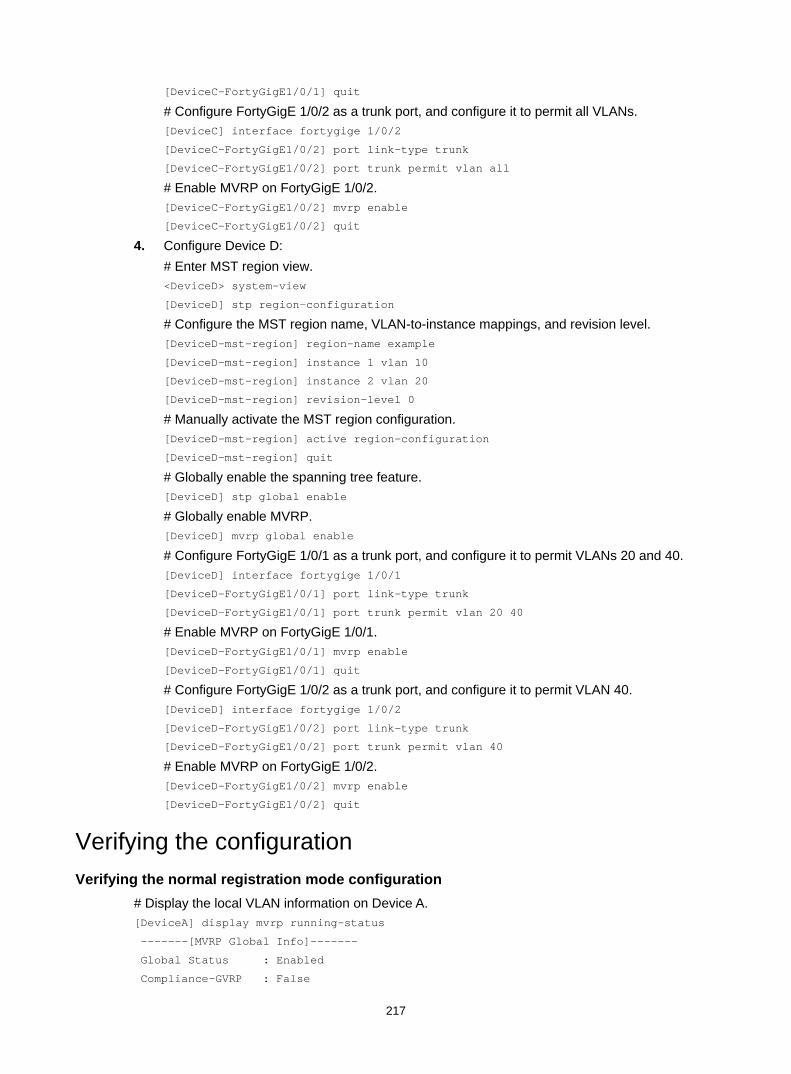
217
[DeviceC-FortyGigE1/0/1] quit
# Configure FortyGigE 1/0/2 as a trunk port, and configure it to permit all VLANs. [DeviceC] interface fortygige 1/0/2
[DeviceC-FortyGigE1/0/2] port link-type trunk
[DeviceC-FortyGigE1/0/2] port trunk permit vlan all
# Enable MVRP on FortyGigE 1/0/2. [DeviceC-FortyGigE1/0/2] mvrp enable
[DeviceC-FortyGigE1/0/2] quit
4. Configure Device D: # Enter MST region view. <DeviceD> system-view
[DeviceD] stp region-configuration
# Configure the MST region name, VLAN-to-instance mappings, and revision level. [DeviceD-mst-region] region-name example
[DeviceD-mst-region] instance 1 vlan 10
[DeviceD-mst-region] instance 2 vlan 20
[DeviceD-mst-region] revision-level 0
# Manually activate the MST region configuration. [DeviceD-mst-region] active region-configuration
[DeviceD-mst-region] quit
# Globally enable the spanning tree feature. [DeviceD] stp global enable
# Globally enable MVRP. [DeviceD] mvrp global enable
# Configure FortyGigE 1/0/1 as a trunk port, and configure it to permit VLANs 20 and 40. [DeviceD] interface fortygige 1/0/1
[DeviceD-FortyGigE1/0/1] port link-type trunk
[DeviceD-FortyGigE1/0/1] port trunk permit vlan 20 40
# Enable MVRP on FortyGigE 1/0/1. [DeviceD-FortyGigE1/0/1] mvrp enable
[DeviceD-FortyGigE1/0/1] quit
# Configure FortyGigE 1/0/2 as a trunk port, and configure it to permit VLAN 40. [DeviceD] interface fortygige 1/0/2
[DeviceD-FortyGigE1/0/2] port link-type trunk
[DeviceD-FortyGigE1/0/2] port trunk permit vlan 40
# Enable MVRP on FortyGigE 1/0/2. [DeviceD-FortyGigE1/0/2] mvrp enable
[DeviceD-FortyGigE1/0/2] quit
Verifying the configuration Verifying the normal registration mode configuration
# Display the local VLAN information on Device A. [DeviceA] display mvrp running-status
-------[MVRP Global Info]-------
Global Status : Enabled
Compliance-GVRP : False
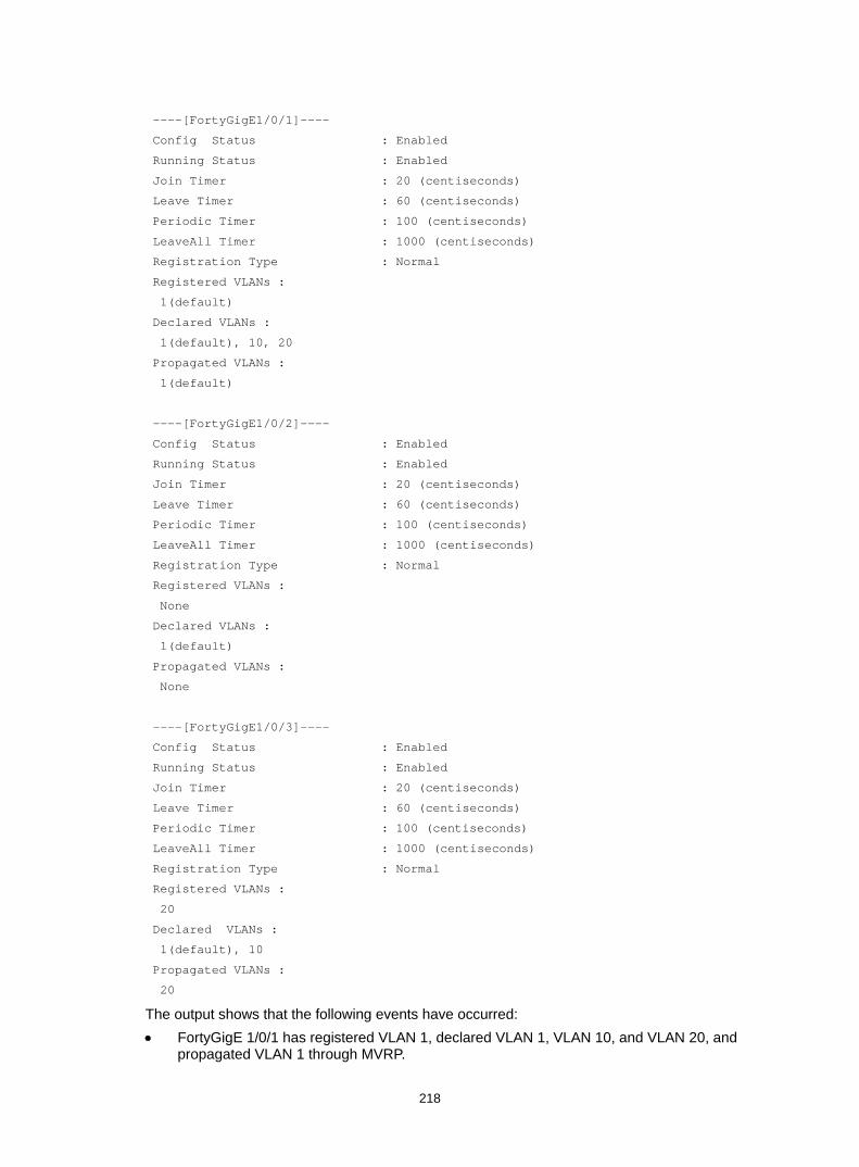
218
----[FortyGigE1/0/1]----
Config Status : Enabled
Running Status : Enabled
Join Timer : 20 (centiseconds)
Leave Timer : 60 (centiseconds)
Periodic Timer : 100 (centiseconds)
LeaveAll Timer : 1000 (centiseconds)
Registration Type : Normal
Registered VLANs :
1(default)
Declared VLANs :
1(default), 10, 20
Propagated VLANs :
1(default)
----[FortyGigE1/0/2]----
Config Status : Enabled
Running Status : Enabled
Join Timer : 20 (centiseconds)
Leave Timer : 60 (centiseconds)
Periodic Timer : 100 (centiseconds)
LeaveAll Timer : 1000 (centiseconds)
Registration Type : Normal
Registered VLANs :
None
Declared VLANs :
1(default)
Propagated VLANs :
None
----[FortyGigE1/0/3]----
Config Status : Enabled
Running Status : Enabled
Join Timer : 20 (centiseconds)
Leave Timer : 60 (centiseconds)
Periodic Timer : 100 (centiseconds)
LeaveAll Timer : 1000 (centiseconds)
Registration Type : Normal
Registered VLANs :
20
Declared VLANs :
1(default), 10
Propagated VLANs :
20
The output shows that the following events have occurred: • FortyGigE 1/0/1 has registered VLAN 1, declared VLAN 1, VLAN 10, and VLAN 20, and
propagated VLAN 1 through MVRP.

219
• FortyGigE 1/0/2 has declared VLAN 1, and registered and propagated no VLANs. • FortyGigE 1/0/3 has registered VLAN 20, declared VLAN 1 and VLAN 10, and propagated
VLAN 20 through MVRP.
# Display the local VLAN information on Device B. [DeviceB] display mvrp running-status
-------[MVRP Global Info]-------
Global Status : Enabled
Compliance-GVRP : False
----[FortyGigE1/0/1]----
Config Status : Enabled
Running Status : Enabled
Join Timer : 20 (centiseconds)
Leave Timer : 60 (centiseconds)
Periodic Timer : 100 (centiseconds)
LeaveAll Timer : 1000 (centiseconds)
Registration Type : Normal
Registered VLANs :
1(default)
Declared VLANs :
1(default), 20
Propagated VLANs :
1(default)
----[FortyGigE1/0/2]----
Config Status : Enabled
Running Status : Enabled
Join Timer : 20 (centiseconds)
Leave Timer : 60 (centiseconds)
Periodic Timer : 100 (centiseconds)
LeaveAll Timer : 1000 (centiseconds)
Registration Type : Normal
Registered VLANs :
1(default), 10
Declared VLANs :
1(default), 20
Propagated VLANs :
1(default)
----[FortyGigE1/0/3]----
Config Status : Enabled
Running Status : Enabled
Join Timer : 20 (centiseconds)
Leave Timer : 60 (centiseconds)
Periodic Timer : 100 (centiseconds)
LeaveAll Timer : 1000 (centiseconds)
Registration Type : Normal
Registered VLANs :
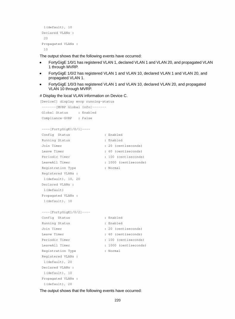
220
1(default), 10
Declared VLANs :
20
Propagated VLANs :
10
The output shows that the following events have occurred: • FortyGigE 1/0/1 has registered VLAN 1, declared VLAN 1 and VLAN 20, and propagated VLAN
1 through MVRP. • FortyGigE 1/0/2 has registered VLAN 1 and VLAN 10, declared VLAN 1 and VLAN 20, and
propagated VLAN 1. • FortyGigE 1/0/3 has registered VLAN 1 and VLAN 10, declared VLAN 20, and propagated
VLAN 10 through MVRP.
# Display the local VLAN information on Device C. [DeviceC] display mvrp running-status
-------[MVRP Global Info]-------
Global Status : Enabled
Compliance-GVRP : False
----[FortyGigE1/0/1]----
Config Status : Enabled
Running Status : Enabled
Join Timer : 20 (centiseconds)
Leave Timer : 60 (centiseconds)
Periodic Timer : 100 (centiseconds)
LeaveAll Timer : 1000 (centiseconds)
Registration Type : Normal
Registered VLANs :
1(default), 10, 20
Declared VLANs :
1(default)
Propagated VLANs :
1(default), 10
----[FortyGigE1/0/2]----
Config Status : Enabled
Running Status : Enabled
Join Timer : 20 (centiseconds)
Leave Timer : 60 (centiseconds)
Periodic Timer : 100 (centiseconds)
LeaveAll Timer : 1000 (centiseconds)
Registration Type : Normal
Registered VLANs :
1(default), 20
Declared VLANs :
1(default), 10
Propagated VLANs :
1(default), 20
The output shows that the following events have occurred:

221
• FortyGigE 1/0/1 has registered VLAN 1, VLAN 10, and VLAN 20, declared VLAN 1, and propagated VLAN 1 and VLAN 10 through MVRP.
• FortyGigE 1/0/2 has registered VLAN 1 and VLAN 20, declared VLAN 1 and VLAN 10, and propagated VLAN 1 and VLAN 20 through MVRP.
# Display the local VLAN information on Device D. [DeviceD] display mvrp running-status
-------[MVRP Global Info]-------
Global Status : Enabled
Compliance-GVRP : False
----[FortyGigE1/0/1]----
Config Status : Enabled
Running Status : Enabled
Join Timer : 20 (centiseconds)
Leave Timer : 60 (centiseconds)
Periodic Timer : 100 (centiseconds)
LeaveAll Timer : 1000 (centiseconds)
Registration Type : Normal
Registered VLANs :
1(default), 20
Declared VLANs :
1(default)
Propagated VLANs :
1(default), 20
----[FortyGigE1/0/2]----
Config Status : Enabled
Running Status : Enabled
Join Timer : 20 (centiseconds)
Leave Timer : 60 (centiseconds)
Periodic Timer : 100 (centiseconds)
LeaveAll Timer : 1000 (centiseconds)
Registration Type : Normal
Registered VLANs :
1(default)
Declared VLANs :
None
Propagated VLANs :
None
The output shows that the following events have occurred: • FortyGigE 1/0/1 has registered and propagated VLAN 10 and VLAN 20, and declared VLAN 1
through MVRP. • Port FortyGigE 1/0/2 has registered VLAN 1, and declared and propagated no VLANs through
MVRP.
Verifying the configuration after changing the registration mode When the network is stable, set the MVRP registration mode to fixed on the port of Device B connected to Device A. Then, verify that dynamic VLANs on the port will not be deregistered.
# Set the MVRP registration mode to fixed on FortyGigE 1/0/3 of Device B.
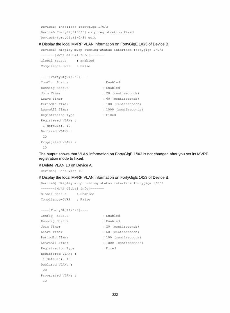
222
[DeviceB] interface fortygige 1/0/3
[DeviceB-FortyGigE1/0/3] mvrp registration fixed
[DeviceB-FortyGigE1/0/3] quit
# Display the local MVRP VLAN information on FortyGigE 1/0/3 of Device B. [DeviceB] display mvrp running-status interface fortygige 1/0/3
-------[MVRP Global Info]-------
Global Status : Enabled
Compliance-GVRP : False
----[FortyGigE1/0/3]----
Config Status : Enabled
Running Status : Enabled
Join Timer : 20 (centiseconds)
Leave Timer : 60 (centiseconds)
Periodic Timer : 100 (centiseconds)
LeaveAll Timer : 1000 (centiseconds)
Registration Type : Fixed
Registered VLANs :
1(default), 10
Declared VLANs :
20
Propagated VLANs :
10
The output shows that VLAN information on FortyGigE 1/0/3 is not changed after you set its MVRP registration mode to fixed.
# Delete VLAN 10 on Device A. [DeviceA] undo vlan 10
# Display the local MVRP VLAN information on FortyGigE 1/0/3 of Device B. [DeviceB] display mvrp running-status interface fortygige 1/0/3
-------[MVRP Global Info]-------
Global Status : Enabled
Compliance-GVRP : False
----[FortyGigE1/0/3]----
Config Status : Enabled
Running Status : Enabled
Join Timer : 20 (centiseconds)
Leave Timer : 60 (centiseconds)
Periodic Timer : 100 (centiseconds)
LeaveAll Timer : 1000 (centiseconds)
Registration Type : Fixed
Registered VLANs :
1(default), 10
Declared VLANs :
20
Propagated VLANs :
10

223
The output shows that the dynamic VLAN information on FortyGigE 1/0/3 is not changed after you set its MVRP registration mode to fixed.
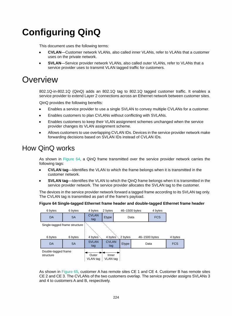
224
Configuring QinQ This document uses the following terms: • CVLAN—Customer network VLANs, also called inner VLANs, refer to VLANs that a customer
uses on the private network. • SVLAN—Service provider network VLANs, also called outer VLANs, refer to VLANs that a
service provider uses to transmit VLAN tagged traffic for customers.
Overview 802.1Q-in-802.1Q (QinQ) adds an 802.1Q tag to 802.1Q tagged customer traffic. It enables a service provider to extend Layer 2 connections across an Ethernet network between customer sites.
QinQ provides the following benefits: • Enables a service provider to use a single SVLAN to convey multiple CVLANs for a customer. • Enables customers to plan CVLANs without conflicting with SVLANs. • Enables customers to keep their VLAN assignment schemes unchanged when the service
provider changes its VLAN assignment scheme. • Allows customers to use overlapping CVLAN IDs. Devices in the service provider network make
forwarding decisions based on SVLAN IDs instead of CVLAN IDs.
How QinQ works As shown in Figure 64, a QinQ frame transmitted over the service provider network carries the following tags: • CVLAN tag—Identifies the VLAN to which the frame belongs when it is transmitted in the
customer network. • SVLAN tag—Identifies the VLAN to which the QinQ frame belongs when it is transmitted in the
service provider network. The service provider allocates the SVLAN tag to the customer.
The devices in the service provider network forward a tagged frame according to its SVLAN tag only. The CVLAN tag is transmitted as part of the frame's payload.
Figure 64 Single-tagged Ethernet frame header and double-tagged Ethernet frame header
As shown in Figure 65, customer A has remote sites CE 1 and CE 4. Customer B has remote sites CE 2 and CE 3. The CVLANs of the two customers overlap. The service provider assigns SVLANs 3 and 4 to customers A and B, respectively.
Etype
DA SA CVLANtag Etype Data FCS
DA SA SVLAN tag Data FCSCVLAN
tag
6 bytes 6 bytes
Single-tagged frame structure
Double-tagged frame structure
4 bytes
6 bytes 6 bytes 4 bytes 4 bytes
4 bytes
4 bytes
2 bytes
2 bytes
46–1500 bytes
46–1500 bytes
Outer VLAN tag
Inner VLAN tag

225
When a tagged frame from CE 1 arrives, PE 1 tags the frame with SVLAN 3. The double-tagged frame travels over the service provider network until it arrives at PE 2. PE 2 removes the SVLAN tag of the frame, and then sends the frame to CE 4.
Figure 65 Typical QinQ application scenario
QinQ implementations QinQ is enabled on a per-port basis. The link type of a QinQ-enabled port can be access, hybrid, or trunk. The QinQ tagging behaviors are the same across these types of ports.
A QinQ-enabled port tags all incoming frames (tagged or untagged) with the PVID tag. • If an incoming frame already has one tag, it becomes a double-tagged frame. • If the frame does not have any 802.1Q tags, it becomes a frame tagged with the PVID.
QinQ provides the most basic VLAN manipulation method to tag all incoming frames (tagged or untagged) with the PVID tag. To perform advanced VLAN manipulations, use VLAN mapping (see "Configuring VLAN mapping") or QoS policies. For example: • To use different SVLANs for different CVLAN tags, use one-to-two VLAN mapping. • To replace the SVLAN ID, CVLAN ID, or both IDs for an incoming double-tagged frame, use
two-to-two VLAN mapping. • To set the 802.1p priority in SVLAN tags, configure a QoS policy as described in "Setting the
802.1p priority in SVLAN tags."
Protocols and standards • IEEE 802.1Q, IEEE Standard for Local and Metropolitan Area Networks-Virtual Bridged Local
Area Networks • IEEE 802.1ad, IEEE Standard for Local and Metropolitan Area Networks-Virtual Bridged Local
Area Networks-Amendment 4: Provider Bridges
PE 1
Service provider network
PE 2
VLANs 1 to 20
Customernetwork B
Customernetwork A
VLANs 1 to 10
VLANs 1 to 10
Customernetwork A
VLANs 1 to 20
Customernetwork B
DataSVLAN 4 CVLAN B
DataSVLAN 3 CVLAN A DataSVLAN 4 CVLAN B
DataSVLAN 3 CVLAN A
DataCVLAN B
DataCVLAN BDataCVLAN A
DataCVLAN A
CE 3 CE 4
CE 1 CE 2
Network
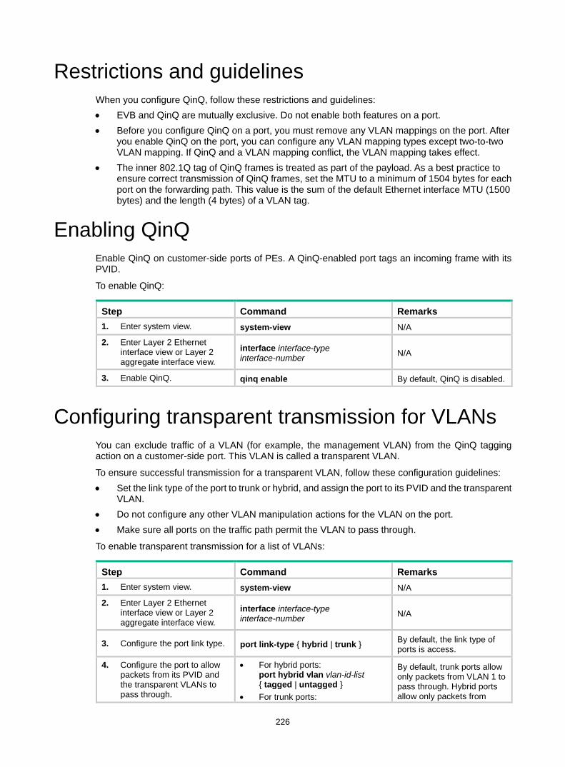
226
Restrictions and guidelines When you configure QinQ, follow these restrictions and guidelines: • EVB and QinQ are mutually exclusive. Do not enable both features on a port. • Before you configure QinQ on a port, you must remove any VLAN mappings on the port. After
you enable QinQ on the port, you can configure any VLAN mapping types except two-to-two VLAN mapping. If QinQ and a VLAN mapping conflict, the VLAN mapping takes effect.
• The inner 802.1Q tag of QinQ frames is treated as part of the payload. As a best practice to ensure correct transmission of QinQ frames, set the MTU to a minimum of 1504 bytes for each port on the forwarding path. This value is the sum of the default Ethernet interface MTU (1500 bytes) and the length (4 bytes) of a VLAN tag.
Enabling QinQ Enable QinQ on customer-side ports of PEs. A QinQ-enabled port tags an incoming frame with its PVID.
To enable QinQ:
Step Command Remarks 1. Enter system view. system-view N/A
2. Enter Layer 2 Ethernet interface view or Layer 2 aggregate interface view.
interface interface-type interface-number N/A
3. Enable QinQ. qinq enable By default, QinQ is disabled.
Configuring transparent transmission for VLANs You can exclude traffic of a VLAN (for example, the management VLAN) from the QinQ tagging action on a customer-side port. This VLAN is called a transparent VLAN.
To ensure successful transmission for a transparent VLAN, follow these configuration guidelines: • Set the link type of the port to trunk or hybrid, and assign the port to its PVID and the transparent
VLAN. • Do not configure any other VLAN manipulation actions for the VLAN on the port. • Make sure all ports on the traffic path permit the VLAN to pass through.
To enable transparent transmission for a list of VLANs:
Step Command Remarks 1. Enter system view. system-view N/A
2. Enter Layer 2 Ethernet interface view or Layer 2 aggregate interface view.
interface interface-type interface-number N/A
3. Configure the port link type. port link-type { hybrid | trunk } By default, the link type of ports is access.
4. Configure the port to allow packets from its PVID and the transparent VLANs to pass through.
• For hybrid ports: port hybrid vlan vlan-id-list { tagged | untagged }
• For trunk ports:
By default, trunk ports allow only packets from VLAN 1 to pass through. Hybrid ports allow only packets from
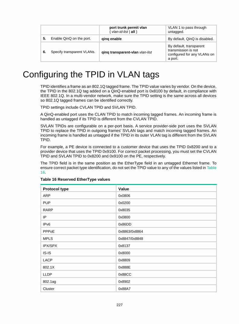
227
port trunk permit vlan { vlan-id-list | all }
VLAN 1 to pass through untagged.
5. Enable QinQ on the port. qinq enable By default, QinQ is disabled.
6. Specify transparent VLANs. qinq transparent-vlan vlan-list By default, transparent transmission is not configured for any VLANs on a port.
Configuring the TPID in VLAN tags TPID identifies a frame as an 802.1Q tagged frame. The TPID value varies by vendor. On the device, the TPID in the 802.1Q tag added on a QinQ-enabled port is 0x8100 by default, in compliance with IEEE 802.1Q. In a multi-vendor network, make sure the TPID setting is the same across all devices so 802.1Q tagged frames can be identified correctly.
TPID settings include CVLAN TPID and SVLAN TPID.
A QinQ-enabled port uses the CLAN TPID to match incoming tagged frames. An incoming frame is handled as untagged if its TPID is different from the CVLAN TPID.
SVLAN TPIDs are configurable on a per-port basis. A service provider-side port uses the SVLAN TPID to replace the TPID in outgoing frames' SVLAN tags and match incoming tagged frames. An incoming frame is handled as untagged if the TPID in its outer VLAN tag is different from the SVLAN TPID.
For example, a PE device is connected to a customer device that uses the TPID 0x8200 and to a provider device that uses the TPID 0x9100. For correct packet processing, you must set the CVLAN TPID and SVLAN TPID to 0x8200 and 0x9100 on the PE, respectively.
The TPID field is in the same position as the EtherType field in an untagged Ethernet frame. To ensure correct packet type identification, do not set the TPID value to any of the values listed in Table 16.
Table 16 Reserved EtherType values
Protocol type Value ARP 0x0806
PUP 0x0200
RARP 0x8035
IP 0x0800
IPv6 0x86DD
PPPoE 0x8863/0x8864
MPLS 0x8847/0x8848
IPX/SPX 0x8137
IS-IS 0x8000
LACP 0x8809
802.1X 0x888E
LLDP 0x88CC
802.1ag 0x8902
Cluster 0x88A7
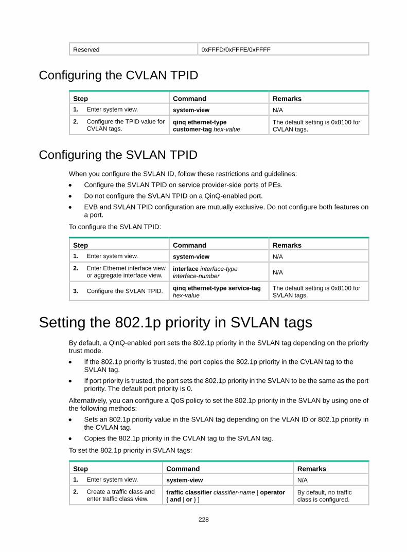
228
Reserved 0xFFFD/0xFFFE/0xFFFF
Configuring the CVLAN TPID
Step Command Remarks 1. Enter system view. system-view N/A
2. Configure the TPID value for CVLAN tags.
qinq ethernet-type customer-tag hex-value
The default setting is 0x8100 for CVLAN tags.
Configuring the SVLAN TPID When you configure the SVLAN ID, follow these restrictions and guidelines: • Configure the SVLAN TPID on service provider-side ports of PEs. • Do not configure the SVLAN TPID on a QinQ-enabled port. • EVB and SVLAN TPID configuration are mutually exclusive. Do not configure both features on
a port.
To configure the SVLAN TPID:
Step Command Remarks 1. Enter system view. system-view N/A
2. Enter Ethernet interface view or aggregate interface view.
interface interface-type interface-number N/A
3. Configure the SVLAN TPID. qinq ethernet-type service-tag hex-value
The default setting is 0x8100 for SVLAN tags.
Setting the 802.1p priority in SVLAN tags By default, a QinQ-enabled port sets the 802.1p priority in the SVLAN tag depending on the priority trust mode. • If the 802.1p priority is trusted, the port copies the 802.1p priority in the CVLAN tag to the
SVLAN tag. • If port priority is trusted, the port sets the 802.1p priority in the SVLAN to be the same as the port
priority. The default port priority is 0.
Alternatively, you can configure a QoS policy to set the 802.1p priority in the SVLAN by using one of the following methods: • Sets an 802.1p priority value in the SVLAN tag depending on the VLAN ID or 802.1p priority in
the CVLAN tag. • Copies the 802.1p priority in the CVLAN tag to the SVLAN tag.
To set the 802.1p priority in SVLAN tags:
Step Command Remarks 1. Enter system view. system-view N/A
2. Create a traffic class and enter traffic class view.
traffic classifier classifier-name [ operator { and | or } ]
By default, no traffic class is configured.
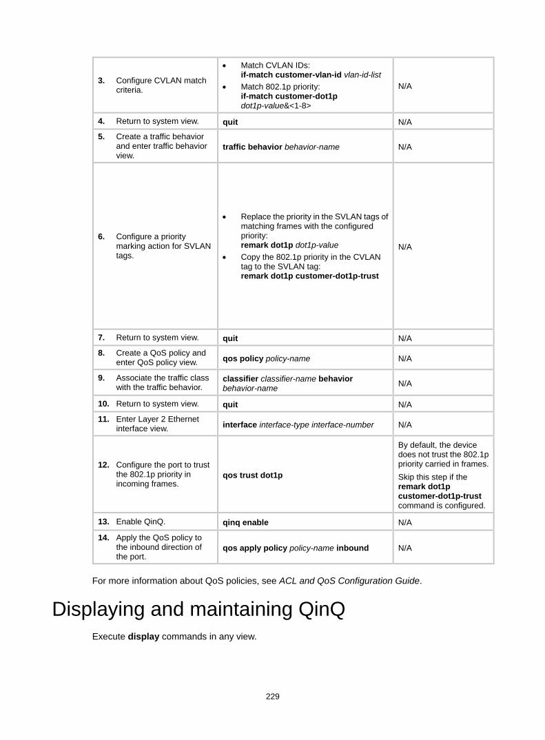
229
3. Configure CVLAN match criteria.
• Match CVLAN IDs: if-match customer-vlan-id vlan-id-list
• Match 802.1p priority: if-match customer-dot1p dot1p-value&<1-8>
N/A
4. Return to system view. quit N/A
5. Create a traffic behavior and enter traffic behavior view.
traffic behavior behavior-name N/A
6. Configure a priority marking action for SVLAN tags.
• Replace the priority in the SVLAN tags of matching frames with the configured priority: remark dot1p dot1p-value
• Copy the 802.1p priority in the CVLAN tag to the SVLAN tag: remark dot1p customer-dot1p-trust
N/A
7. Return to system view. quit N/A
8. Create a QoS policy and enter QoS policy view. qos policy policy-name N/A
9. Associate the traffic class with the traffic behavior.
classifier classifier-name behavior behavior-name N/A
10. Return to system view. quit N/A
11. Enter Layer 2 Ethernet interface view. interface interface-type interface-number N/A
12. Configure the port to trust the 802.1p priority in incoming frames.
qos trust dot1p
By default, the device does not trust the 802.1p priority carried in frames. Skip this step if the remark dot1p customer-dot1p-trust command is configured.
13. Enable QinQ. qinq enable N/A
14. Apply the QoS policy to the inbound direction of the port.
qos apply policy policy-name inbound N/A
For more information about QoS policies, see ACL and QoS Configuration Guide.
Displaying and maintaining QinQ Execute display commands in any view.
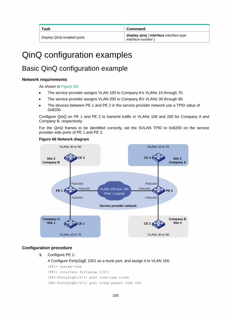
230
Task Command
Display QinQ-enabled ports. display qinq [ interface interface-type interface-number ]
QinQ configuration examples Basic QinQ configuration example Network requirements
As shown in Figure 66: • The service provider assigns VLAN 100 to Company A's VLANs 10 through 70. • The service provider assigns VLAN 200 to Company B's VLANs 30 through 90. • The devices between PE 1 and PE 2 in the service provider network use a TPID value of
0x8200.
Configure QinQ on PE 1 and PE 2 to transmit traffic in VLANs 100 and 200 for Company A and Company B, respectively.
For the QinQ frames to be identified correctly, set the SVLAN TPID to 0x8200 on the service provider-side ports of PE 1 and PE 2.
Figure 66 Network diagram
Configuration procedure 1. Configure PE 1:
# Configure FortyGigE 1/0/1 as a trunk port, and assign it to VLAN 100. <PE1> system-view
[PE1] interface fortygige 1/0/1
[PE1-FortyGigE1/0/1] port link-type trunk
[PE1-FortyGigE1/0/1] port trunk permit vlan 100
CE 1Company A
Site 1
PE 1
Service provider network
VLANs 100 and 200TPID = 0x8200
PE 2
FGE1/0/1
FGE1/0/2
FGE1/0/1
FGE1/0/2
CE 2
VLANs 10 to 70
VLANs 30 to 90
Site 3Company B
CE 3
Company BSite 4
VLANs 30 to 90
Site 2Company A
VLANs 10 to 70
FGE1/0/3 FGE1/0/3
CE 4
231
# Configure VLAN 100 as the PVID for FortyGigE 1/0/1. [PE1-FortyGigE1/0/1] port trunk pvid vlan 100
# Enable QinQ on FortyGigE 1/0/1. [PE1-FortyGigE1/0/1] qinq enable
[PE1-FortyGigE1/0/1] quit
# Configure FortyGigE 1/0/2 as a trunk port, and assign it to VLANs 100 and 200. [PE1] interface fortygige 1/0/2
[PE1-FortyGigE1/0/2] port link-type trunk
[PE1-FortyGigE1/0/2] port trunk permit vlan 100 200
# Set the TPID value in the SVLAN tags to 0x8200 on FortyGigE 1/0/2. [PE1-FortyGigE1/0/2] qinq ethernet-type service-tag 8200
[PE1-FortyGigE1/0/2] quit
# Configure FortyGigE 1/0/3 as a trunk port, and assign it to VLAN 200. [PE1] interface fortygige 1/0/3
[PE1-FortyGigE1/0/3] port link-type trunk
[PE1-FortyGigE1/0/3] port trunk permit vlan 200
# Configure VLAN 200 as the PVID for FortyGigE 1/0/3. [PE1-FortyGigE1/0/3] port trunk pvid vlan 200
# Enable QinQ on FortyGigE 1/0/3. [PE1-FortyGigE1/0/3] qinq enable
[PE1-FortyGigE1/0/3] quit
2. Configure PE 2: # Configure FortyGigE 1/0/1 as a trunk port, and assign it to VLAN 200. <PE2> system-view
[PE2] interface fortygige 1/0/1
[PE2-FortyGigE1/0/1] port link-type trunk
[PE2-FortyGigE1/0/1] port trunk permit vlan 200
# Configure VLAN 200 as the PVID for FortyGigE 1/0/1. [PE2-FortyGigE1/0/1] port trunk pvid vlan 200
# Enable QinQ on FortyGigE 1/0/1. [PE2-FortyGigE1/0/1] qinq enable
[PE2-FortyGigE1/0/1] quit
# Configure FortyGigE 1/0/2 as a trunk port, and assign it to VLANs 100 and 200. [PE2] interface fortygige 1/0/2
[PE2-FortyGigE1/0/2] port link-type trunk
[PE2-FortyGigE1/0/2] port trunk permit vlan 100 200
# Set the TPID value in the SVLAN tags to 0x8200 on FortyGigE 1/0/2. [PE2-FortyGigE1/0/2] qinq ethernet-type service-tag 8200
[PE2-FortyGigE1/0/2] quit
# Configure FortyGigE 1/0/3 as a trunk port, and assign it to VLAN 100. [PE2] interface fortygige 1/0/3
[PE2-FortyGigE1/0/3] port link-type trunk
[PE2-FortyGigE1/0/3] port trunk permit vlan 100
# Configure VLAN 100 as the PVID for FortyGigE 1/0/3. [PE2-FortyGigE1/0/3] port trunk pvid vlan 100
# Enable QinQ on FortyGigE 1/0/3. [PE2-FortyGigE1/0/3] qinq enable
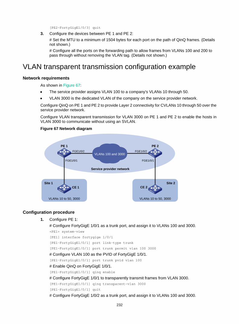
232
[PE2-FortyGigE1/0/3] quit
3. Configure the devices between PE 1 and PE 2: # Set the MTU to a minimum of 1504 bytes for each port on the path of QinQ frames. (Details not shown.) # Configure all the ports on the forwarding path to allow frames from VLANs 100 and 200 to pass through without removing the VLAN tag. (Details not shown.)
VLAN transparent transmission configuration example Network requirements
As shown in Figure 67: • The service provider assigns VLAN 100 to a company's VLANs 10 through 50. • VLAN 3000 is the dedicated VLAN of the company on the service provider network.
Configure QinQ on PE 1 and PE 2 to provide Layer 2 connectivity for CVLANs 10 through 50 over the service provider network.
Configure VLAN transparent transmission for VLAN 3000 on PE 1 and PE 2 to enable the hosts in VLAN 3000 to communicate without using an SVLAN.
Figure 67 Network diagram
Configuration procedure 1. Configure PE 1:
# Configure FortyGigE 1/0/1 as a trunk port, and assign it to VLANs 100 and 3000. <PE1> system-view
[PE1] interface fortygige 1/0/1
[PE1-FortyGigE1/0/1] port link-type trunk
[PE1-FortyGigE1/0/1] port trunk permit vlan 100 3000
# Configure VLAN 100 as the PVID of FortyGigE 1/0/1. [PE1-FortyGigE1/0/1] port trunk pvid vlan 100
# Enable QinQ on FortyGigE 1/0/1. [PE1-FortyGigE1/0/1] qinq enable
# Configure FortyGigE 1/0/1 to transparently transmit frames from VLAN 3000. [PE1-FortyGigE1/0/1] qinq transparent-vlan 3000
[PE1-FortyGigE1/0/1] quit
# Configure FortyGigE 1/0/2 as a trunk port, and assign it to VLANs 100 and 3000.
CE 1
PE 1
Service provider network
VLANs 100 and 3000
PE 2
FGE1/0/1
FGE1/0/2
FGE1/0/1
FGE1/0/2
CE 2
VLANs 10 to 50, 3000 VLANs 10 to 50, 3000
Site 1 Site 2
233
[PE1] interface fortygige 1/0/2
[PE1-FortyGigE1/0/2] port link-type trunk
[PE1-FortyGigE1/0/2] port trunk permit vlan 100 3000
[PE1-FortyGigE1/0/2] quit
2. Configure PE 2: # Configure FortyGigE 1/0/1 as a trunk port, and assign it to VLANs 100 and 3000. <PE2> system-view
[PE2] interface fortygige 1/0/1
[PE2-FortyGigE1/0/1] port link-type trunk
[PE2-FortyGigE1/0/1] port trunk permit vlan 100 3000
# Configure VLAN 100 as the PVID of FortyGigE 1/0/1. [PE1-FortyGigE1/0/1] port trunk pvid vlan 100
# Enable QinQ on FortyGigE 1/0/1. [PE2-FortyGigE1/0/1] qinq enable
# Configure FortyGigE 1/0/1 to transparently transmit frames from VLAN 3000. [PE2-FortyGigE1/0/1] qinq transparent-vlan 3000
[PE2-FortyGigE1/0/1] quit
# Configure FortyGigE 1/0/2 as a trunk port, and assign it to VLANs 100 and 3000. [PE2] interface fortygige 1/0/2
[PE2-FortyGigE1/0/2] port link-type trunk
[PE2-FortyGigE1/0/2] port trunk permit vlan 100 3000
3. Configure the devices between PE 1 and PE 2: # Set the MTU to a minimum of 1504 bytes for each port on the path of QinQ frames. (Details not shown.) # Configure all the ports on the forwarding path to allow frames from VLANs 100 and 3000 to pass through without removing the VLAN tag. (Details not shown.)
234
Configuring VLAN mapping Overview
VLAN mapping re-marks VLAN tagged traffic with new VLAN IDs. H3C provides the following types of VLAN mapping: • One-to-one VLAN mapping—Replaces one VLAN tag with another. • Many-to-one VLAN mapping—Replaces multiple VLAN tags with the same VLAN tag. • One-to-two VLAN mapping—Tags single-tagged packets with an outer VLAN tag. • Two-to-two VLAN mapping—Replaces the SVLAN ID, CVLAN ID, or both IDs for an incoming
double-tagged frame.
Application scenario of one-to-one and many-to-one VLAN mapping
Figure 68 shows a typical application scenario of one-to-one and many-to-one VLAN mapping. The scenario implements broadband Internet access for a community.
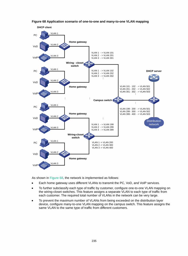
235
Figure 68 Application scenario of one-to-one and many-to-one VLAN mapping
As shown in Figure 68, the network is implemented as follows: • Each home gateway uses different VLANs to transmit the PC, VoD, and VoIP services. • To further subclassify each type of traffic by customer, configure one-to-one VLAN mapping on
the wiring-closet switches. This feature assigns a separate VLAN to each type of traffic from each customer. The required total number of VLANs in the network can be very large.
• To prevent the maximum number of VLANs from being exceeded on the distribution layer device, configure many-to-one VLAN mapping on the campus switch. This feature assigns the same VLAN to the same type of traffic from different customers.
VLAN 101 - 102 - > VLAN 501VLAN 201 - 202 - > VLAN 502VLAN 301 - 302 - > VLAN 503
...Campus switch
Distribution network
DHCP client
DHCP server
...
Wiring - closet switch
VLAN 1 - > VLAN 101VLAN 2 - > VLAN 201VLAN 3 - > VLAN 301
VLAN 1 - > VLAN 102VLAN 2 - > VLAN 202VLAN 3 - > VLAN 302
PC
VoD
VoIP
VLAN 2Home gateway
VLAN 1
VLAN 3
PC
VoD
VoIP
VLAN 2
Home gateway
VLAN 1
VLAN 3
Wiring-closet switch
VLAN 1 - > VLAN 199VLAN 2 - > VLAN 299VLAN 3 - > VLAN 399
VLAN 1 -> VLAN 200VLAN 2 -> VLAN 300VLAN 3 -> VLAN 400
PC
VoD
VoIP
VLAN 2Home gateway
VLAN 1
VLAN 3
PC
VoD
VoIP
VLAN 2
Home gateway
VLAN 1
VLAN 3
...
VLAN 199 - 200 - > VLAN 501VLAN 299 - 300 - > VLAN 502VLAN 399 - 400 - > VLAN 503
...
...
...
...

236
Application scenario of one-to-two and two-to-two VLAN mapping
Figure 69 shows a typical application scenario of one-to-two and two-to-two VLAN mapping. In this scenario, the remote sites of the same VPN must communicate across two SP networks.
Figure 69 Application scenario of one-to-two and two-to-two VLAN mapping
Site 1 and Site 2 are in VLAN 2 and VLAN 3, respectively. The SP 1 network assigns SVLAN 10 to Site 1. The SP 2 network assigns SVLAN 20 to Site 2. When the packet from Site 1 arrives at PE 1, PE 1 tags the packet with SVLAN 10 by using one-to-two VLAN mapping.
When the double-tagged packet from the SP 1 network arrives at the SP 2 network interface, PE 3 processes the packet as follows: • Replaces SVLAN tag 10 with SVLAN tag 20. • Replaces CVLAN tag 2 with CVLAN tag 3.
One-to-two VLAN mapping provides the following benefits: • Enables a customer network to plan its CVLAN assignment without conflicting with SVLANs. • Adds a VLAN tag to a tagged packet and expands the number of available VLANs to 4094 ×
4094. • Reduces the stress on the SVLAN resources, which were 4094 VLANs in the SP network
before the mapping process was initiated.
VLAN mapping implementations Figure 70 shows a simplified network that illustrates basic VLAN mapping terms.
Basic VLAN mapping terms include the following: • Uplink traffic—Traffic transmitted from the customer network to the service provider network. • Downlink traffic—Traffic transmitted from the service provider network to the customer
network. • Network-side port—A port connected to or closer to the service provider network. • Customer-side port—A port connected to or closer to the customer network.
PE 1
VPN ASite 1
SP 1
CE 1VPN ASite 2
SP 2
CE 2
DataVLAN 2
DataVLAN 10 VLAN 2 DataVLAN 20 VLAN 3
DataVLAN 3
Traffic
One-to-two VLAN mapping
PE 2 PE 3 PE 4
Two-to-two VLAN mapping
One-to-two VLAN mapping
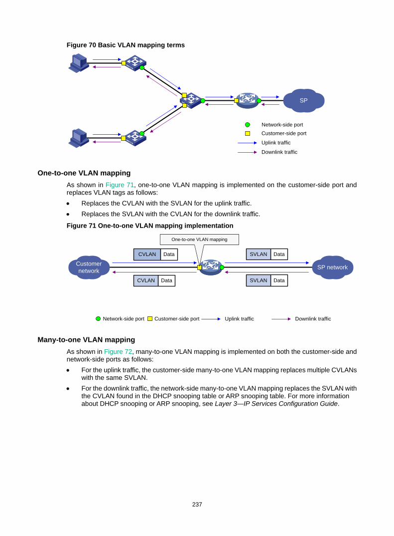
237
Figure 70 Basic VLAN mapping terms
One-to-one VLAN mapping As shown in Figure 71, one-to-one VLAN mapping is implemented on the customer-side port and replaces VLAN tags as follows: • Replaces the CVLAN with the SVLAN for the uplink traffic. • Replaces the SVLAN with the CVLAN for the downlink traffic.
Figure 71 One-to-one VLAN mapping implementation
Many-to-one VLAN mapping As shown in Figure 72, many-to-one VLAN mapping is implemented on both the customer-side and network-side ports as follows: • For the uplink traffic, the customer-side many-to-one VLAN mapping replaces multiple CVLANs
with the same SVLAN. • For the downlink traffic, the network-side many-to-one VLAN mapping replaces the SVLAN with
the CVLAN found in the DHCP snooping table or ARP snooping table. For more information about DHCP snooping or ARP snooping, see Layer 3—IP Services Configuration Guide.
SP
Network-side portCustomer-side port
Uplink traffic
Downlink traffic
Customer network SP network
DataSVLAN
DataSVLANDataCVLAN
One-to-one VLAN mapping
CVLAN Data
Network-side port Customer-side port Uplink traffic Downlink traffic
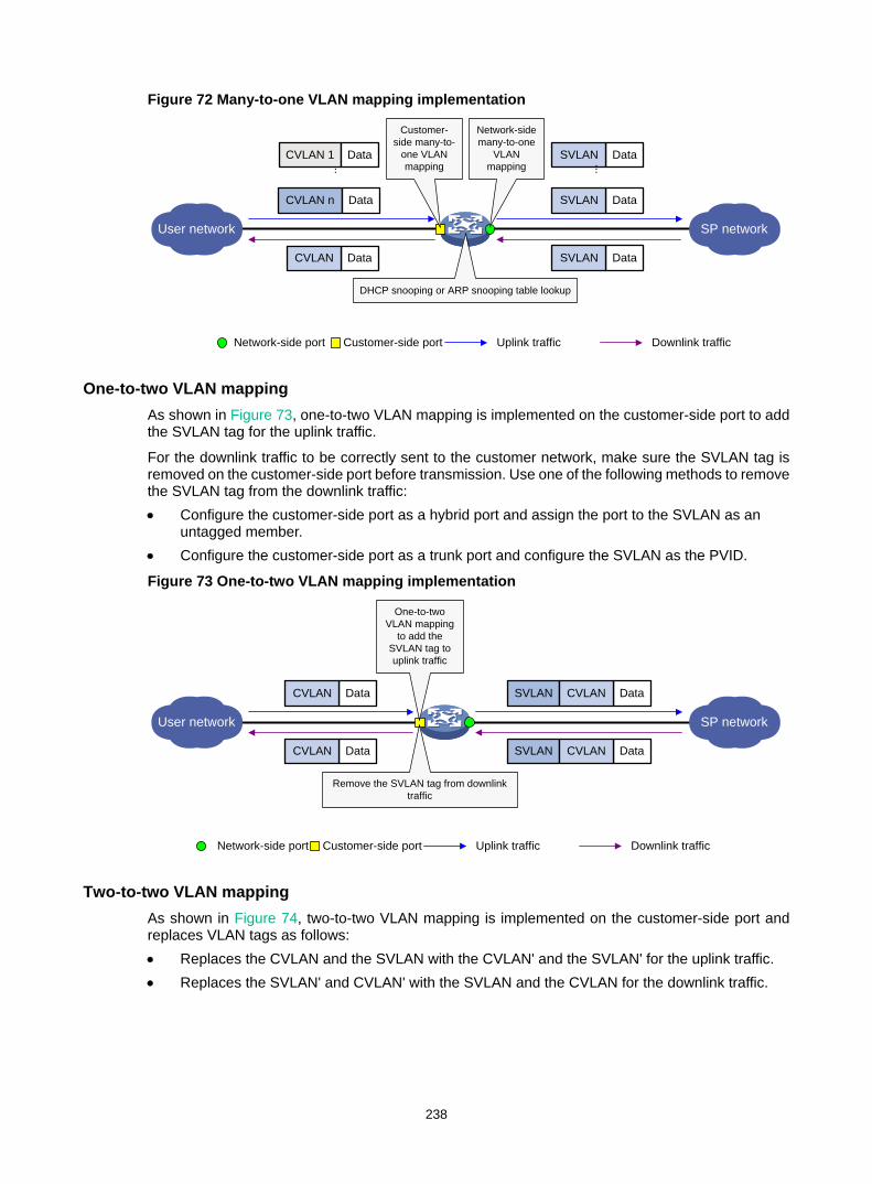
238
Figure 72 Many-to-one VLAN mapping implementation
One-to-two VLAN mapping As shown in Figure 73, one-to-two VLAN mapping is implemented on the customer-side port to add the SVLAN tag for the uplink traffic.
For the downlink traffic to be correctly sent to the customer network, make sure the SVLAN tag is removed on the customer-side port before transmission. Use one of the following methods to remove the SVLAN tag from the downlink traffic: • Configure the customer-side port as a hybrid port and assign the port to the SVLAN as an
untagged member. • Configure the customer-side port as a trunk port and configure the SVLAN as the PVID.
Figure 73 One-to-two VLAN mapping implementation
Two-to-two VLAN mapping As shown in Figure 74, two-to-two VLAN mapping is implemented on the customer-side port and replaces VLAN tags as follows: • Replaces the CVLAN and the SVLAN with the CVLAN' and the SVLAN' for the uplink traffic. • Replaces the SVLAN' and CVLAN' with the SVLAN and the CVLAN for the downlink traffic.
User network SP network
DataSVLAN
DataSVLAN
DHCP snooping or ARP snooping table lookup
Network-side port Customer-side port Uplink traffic Downlink traffic
DataSVLAN...
Network-side many-to-one
VLAN mapping
Customer-side many-to-
one VLAN mapping
DataCVLAN
CVLAN n Data
...CVLAN 1 Data
User network SP network
DataCVLAN
DataCVLAN
One-to-two VLAN mapping
to add the SVLAN tag to uplink traffic
Remove the SVLAN tag from downlink traffic
SVLAN DataCVLAN
SVLAN DataCVLAN
Network-side port Customer-side port Uplink traffic Downlink traffic
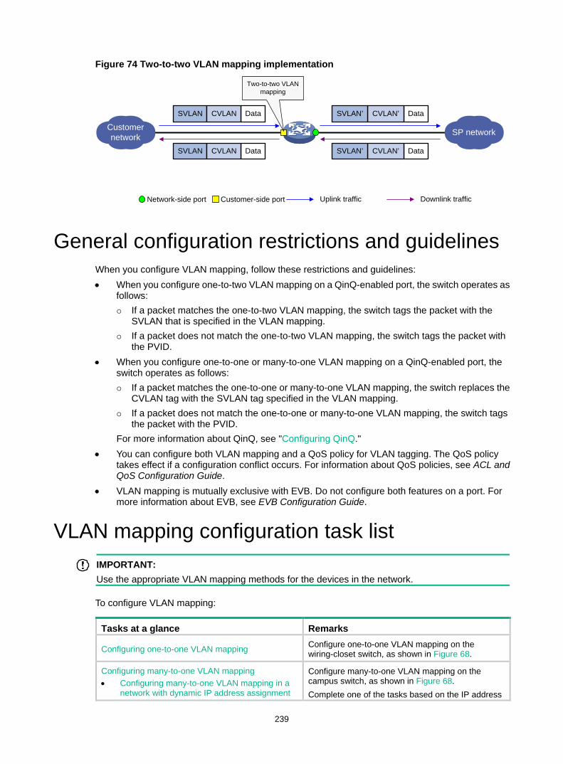
239
Figure 74 Two-to-two VLAN mapping implementation
General configuration restrictions and guidelines When you configure VLAN mapping, follow these restrictions and guidelines: • When you configure one-to-two VLAN mapping on a QinQ-enabled port, the switch operates as
follows: If a packet matches the one-to-two VLAN mapping, the switch tags the packet with the
SVLAN that is specified in the VLAN mapping. If a packet does not match the one-to-two VLAN mapping, the switch tags the packet with
the PVID. • When you configure one-to-one or many-to-one VLAN mapping on a QinQ-enabled port, the
switch operates as follows: If a packet matches the one-to-one or many-to-one VLAN mapping, the switch replaces the
CVLAN tag with the SVLAN tag specified in the VLAN mapping. If a packet does not match the one-to-one or many-to-one VLAN mapping, the switch tags
the packet with the PVID. For more information about QinQ, see "Configuring QinQ."
• You can configure both VLAN mapping and a QoS policy for VLAN tagging. The QoS policy takes effect if a configuration conflict occurs. For information about QoS policies, see ACL and QoS Configuration Guide.
• VLAN mapping is mutually exclusive with EVB. Do not configure both features on a port. For more information about EVB, see EVB Configuration Guide.
VLAN mapping configuration task list IMPORTANT:
Use the appropriate VLAN mapping methods for the devices in the network.
To configure VLAN mapping:
Tasks at a glance Remarks
Configuring one-to-one VLAN mapping Configure one-to-one VLAN mapping on the wiring-closet switch, as shown in Figure 68.
Configuring many-to-one VLAN mapping • Configuring many-to-one VLAN mapping in a
network with dynamic IP address assignment
Configure many-to-one VLAN mapping on the campus switch, as shown in Figure 68. Complete one of the tasks based on the IP address
Network-side port Customer-side port Uplink traffic Downlink traffic
Customer network SP network
SVLAN DataCVLAN
SVLAN DataCVLAN
Two-to-two VLAN mapping
DataCVLAN’SVLAN’
DataCVLAN’SVLAN’
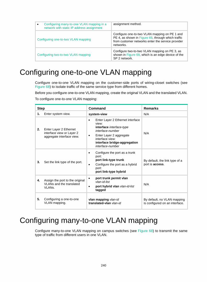
240
• Configuring many-to-one VLAN mapping in a network with static IP address assignment
assignment method.
Configuring one-to-two VLAN mapping
Configure one-to-two VLAN mapping on PE 1 and PE 4, as shown in Figure 69, through which traffic from customer networks enter the service provider networks.
Configuring two-to-two VLAN mapping Configure two-to-two VLAN mapping on PE 3, as shown in Figure 69, which is an edge device of the SP 2 network.
Configuring one-to-one VLAN mapping Configure one-to-one VLAN mapping on the customer-side ports of wiring-closet switches (see Figure 68) to isolate traffic of the same service type from different homes.
Before you configure one-to-one VLAN mapping, create the original VLAN and the translated VLAN.
To configure one-to-one VLAN mapping:
Step Command Remarks 1. Enter system view. system-view N/A
2. Enter Layer 2 Ethernet interface view or Layer 2 aggregate interface view.
• Enter Layer 2 Ethernet interface view: interface interface-type interface-number
• Enter Layer 2 aggregate interface view: interface bridge-aggregation interface-number
N/A
3. Set the link type of the port.
• Configure the port as a trunk port: port link-type trunk
• Configure the port as a hybrid port: port link-type hybrid
By default, the link type of a port is access.
4. Assign the port to the original VLANs and the translated VLANs.
• port trunk permit vlan vlan-id-list
• port hybrid vlan vlan-id-list tagged
N/A
5. Configuring a one-to-one VLAN mapping.
vlan mapping vlan-id translated-vlan vlan-id
By default, no VLAN mapping is configured on an interface.
Configuring many-to-one VLAN mapping Configure many-to-one VLAN mapping on campus switches (see Figure 68) to transmit the same type of traffic from different users in one VLAN.
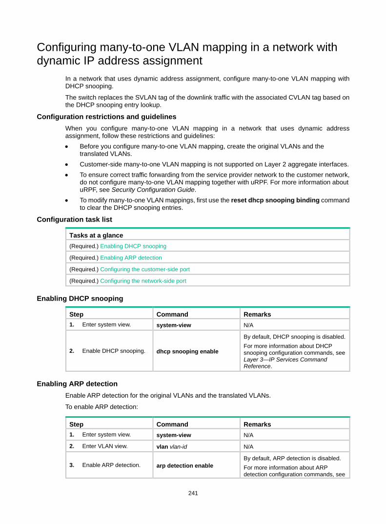
241
Configuring many-to-one VLAN mapping in a network with dynamic IP address assignment
In a network that uses dynamic address assignment, configure many-to-one VLAN mapping with DHCP snooping.
The switch replaces the SVLAN tag of the downlink traffic with the associated CVLAN tag based on the DHCP snooping entry lookup.
Configuration restrictions and guidelines When you configure many-to-one VLAN mapping in a network that uses dynamic address assignment, follow these restrictions and guidelines: • Before you configure many-to-one VLAN mapping, create the original VLANs and the
translated VLANs. • Customer-side many-to-one VLAN mapping is not supported on Layer 2 aggregate interfaces. • To ensure correct traffic forwarding from the service provider network to the customer network,
do not configure many-to-one VLAN mapping together with uRPF. For more information about uRPF, see Security Configuration Guide.
• To modify many-to-one VLAN mappings, first use the reset dhcp snooping binding command to clear the DHCP snooping entries.
Configuration task list
Tasks at a glance (Required.) Enabling DHCP snooping
(Required.) Enabling ARP detection
(Required.) Configuring the customer-side port
(Required.) Configuring the network-side port
Enabling DHCP snooping
Step Command Remarks 1. Enter system view. system-view N/A
2. Enable DHCP snooping. dhcp snooping enable
By default, DHCP snooping is disabled. For more information about DHCP snooping configuration commands, see Layer 3—IP Services Command Reference.
Enabling ARP detection Enable ARP detection for the original VLANs and the translated VLANs.
To enable ARP detection:
Step Command Remarks 1. Enter system view. system-view N/A
2. Enter VLAN view. vlan vlan-id N/A
3. Enable ARP detection. arp detection enable By default, ARP detection is disabled. For more information about ARP detection configuration commands, see
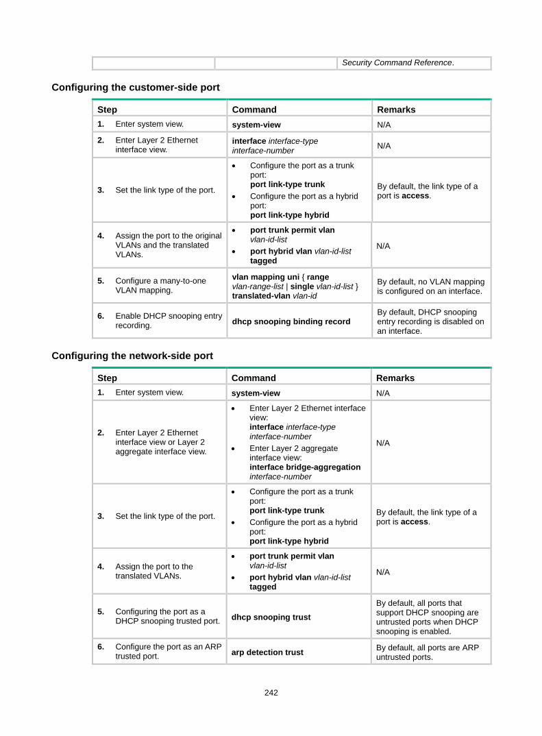
242
Security Command Reference.
Configuring the customer-side port
Step Command Remarks 1. Enter system view. system-view N/A
2. Enter Layer 2 Ethernet interface view.
interface interface-type interface-number N/A
3. Set the link type of the port.
• Configure the port as a trunk port: port link-type trunk
• Configure the port as a hybrid port: port link-type hybrid
By default, the link type of a port is access.
4. Assign the port to the original VLANs and the translated VLANs.
• port trunk permit vlan vlan-id-list
• port hybrid vlan vlan-id-list tagged
N/A
5. Configure a many-to-one VLAN mapping.
vlan mapping uni { range vlan-range-list | single vlan-id-list } translated-vlan vlan-id
By default, no VLAN mapping is configured on an interface.
6. Enable DHCP snooping entry recording. dhcp snooping binding record
By default, DHCP snooping entry recording is disabled on an interface.
Configuring the network-side port
Step Command Remarks 1. Enter system view. system-view N/A
2. Enter Layer 2 Ethernet interface view or Layer 2 aggregate interface view.
• Enter Layer 2 Ethernet interface view: interface interface-type interface-number
• Enter Layer 2 aggregate interface view: interface bridge-aggregation interface-number
N/A
3. Set the link type of the port.
• Configure the port as a trunk port: port link-type trunk
• Configure the port as a hybrid port: port link-type hybrid
By default, the link type of a port is access.
4. Assign the port to the translated VLANs.
• port trunk permit vlan vlan-id-list
• port hybrid vlan vlan-id-list tagged
N/A
5. Configuring the port as a DHCP snooping trusted port. dhcp snooping trust
By default, all ports that support DHCP snooping are untrusted ports when DHCP snooping is enabled.
6. Configure the port as an ARP trusted port. arp detection trust By default, all ports are ARP
untrusted ports.
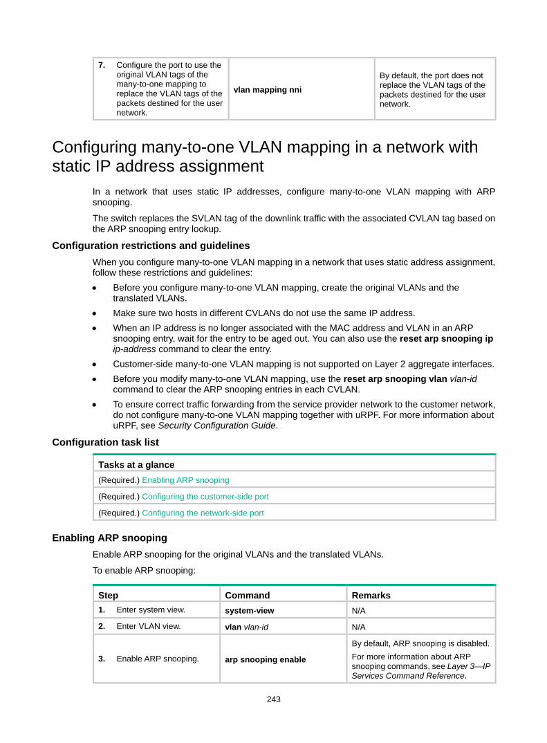
243
7. Configure the port to use the original VLAN tags of the many-to-one mapping to replace the VLAN tags of the packets destined for the user network.
vlan mapping nni By default, the port does not replace the VLAN tags of the packets destined for the user network.
Configuring many-to-one VLAN mapping in a network with static IP address assignment
In a network that uses static IP addresses, configure many-to-one VLAN mapping with ARP snooping.
The switch replaces the SVLAN tag of the downlink traffic with the associated CVLAN tag based on the ARP snooping entry lookup.
Configuration restrictions and guidelines When you configure many-to-one VLAN mapping in a network that uses static address assignment, follow these restrictions and guidelines: • Before you configure many-to-one VLAN mapping, create the original VLANs and the
translated VLANs. • Make sure two hosts in different CVLANs do not use the same IP address. • When an IP address is no longer associated with the MAC address and VLAN in an ARP
snooping entry, wait for the entry to be aged out. You can also use the reset arp snooping ip ip-address command to clear the entry.
• Customer-side many-to-one VLAN mapping is not supported on Layer 2 aggregate interfaces. • Before you modify many-to-one VLAN mapping, use the reset arp snooping vlan vlan-id
command to clear the ARP snooping entries in each CVLAN. • To ensure correct traffic forwarding from the service provider network to the customer network,
do not configure many-to-one VLAN mapping together with uRPF. For more information about uRPF, see Security Configuration Guide.
Configuration task list
Tasks at a glance (Required.) Enabling ARP snooping
(Required.) Configuring the customer-side port
(Required.) Configuring the network-side port
Enabling ARP snooping Enable ARP snooping for the original VLANs and the translated VLANs.
To enable ARP snooping:
Step Command Remarks 1. Enter system view. system-view N/A
2. Enter VLAN view. vlan vlan-id N/A
3. Enable ARP snooping. arp snooping enable
By default, ARP snooping is disabled. For more information about ARP snooping commands, see Layer 3—IP Services Command Reference.
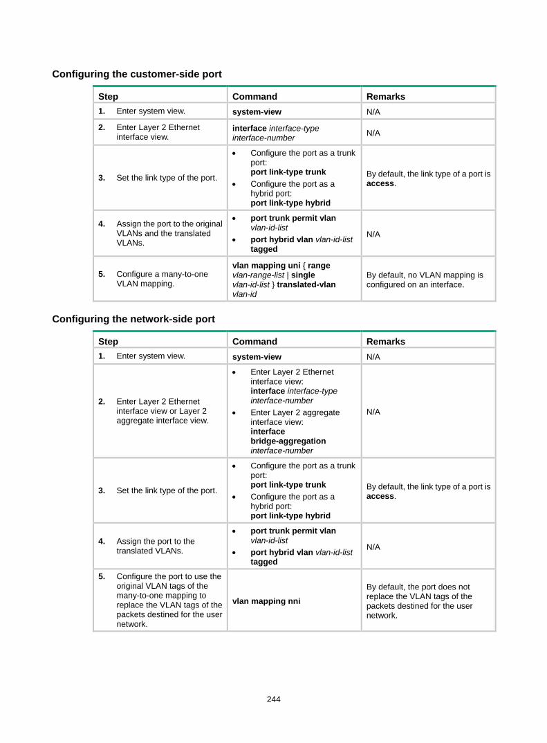
244
Configuring the customer-side port
Step Command Remarks 1. Enter system view. system-view N/A
2. Enter Layer 2 Ethernet interface view.
interface interface-type interface-number N/A
3. Set the link type of the port.
• Configure the port as a trunk port: port link-type trunk
• Configure the port as a hybrid port: port link-type hybrid
By default, the link type of a port is access.
4. Assign the port to the original VLANs and the translated VLANs.
• port trunk permit vlan vlan-id-list
• port hybrid vlan vlan-id-list tagged
N/A
5. Configure a many-to-one VLAN mapping.
vlan mapping uni { range vlan-range-list | single vlan-id-list } translated-vlan vlan-id
By default, no VLAN mapping is configured on an interface.
Configuring the network-side port
Step Command Remarks 1. Enter system view. system-view N/A
2. Enter Layer 2 Ethernet interface view or Layer 2 aggregate interface view.
• Enter Layer 2 Ethernet interface view: interface interface-type interface-number
• Enter Layer 2 aggregate interface view: interface bridge-aggregation interface-number
N/A
3. Set the link type of the port.
• Configure the port as a trunk port: port link-type trunk
• Configure the port as a hybrid port: port link-type hybrid
By default, the link type of a port is access.
4. Assign the port to the translated VLANs.
• port trunk permit vlan vlan-id-list
• port hybrid vlan vlan-id-list tagged
N/A 5. Configure the port to use the
original VLAN tags of the many-to-one mapping to replace the VLAN tags of the packets destined for the user network.
vlan mapping nni By default, the port does not replace the VLAN tags of the packets destined for the user network.
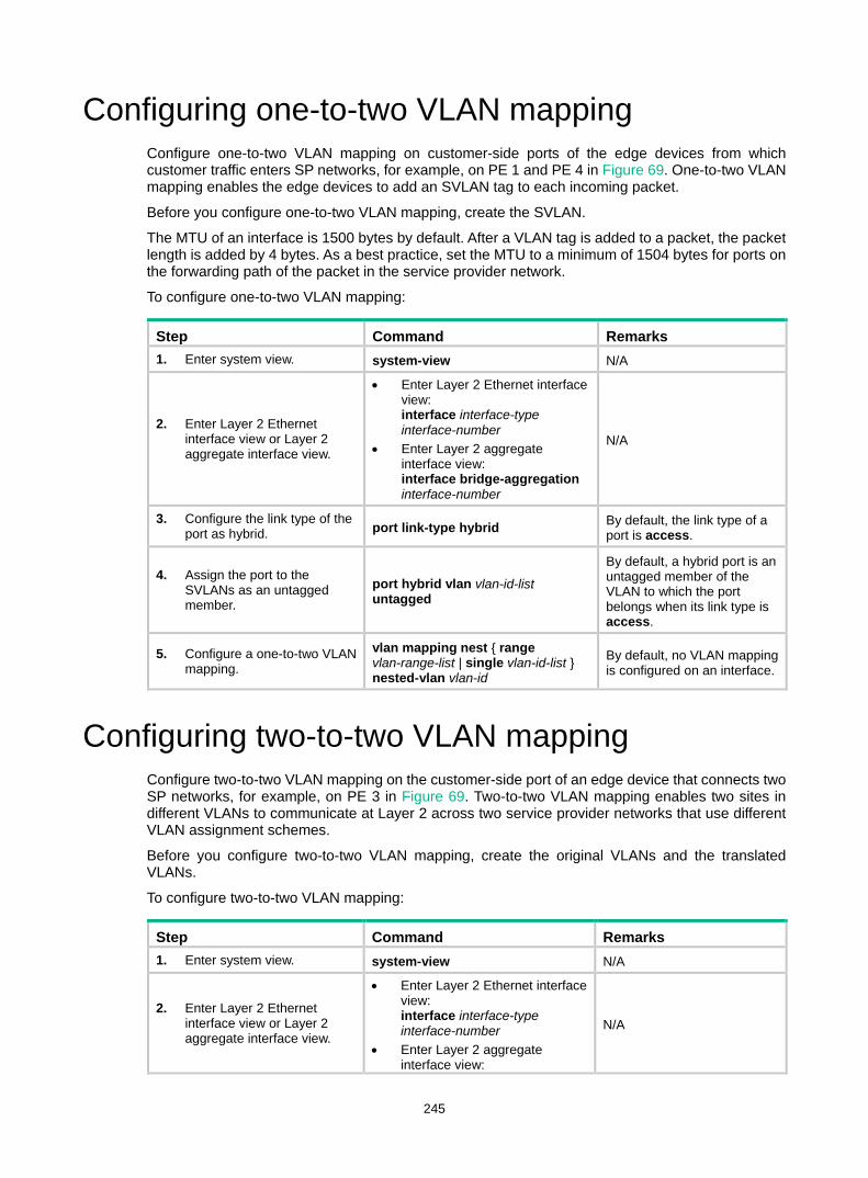
245
Configuring one-to-two VLAN mapping Configure one-to-two VLAN mapping on customer-side ports of the edge devices from which customer traffic enters SP networks, for example, on PE 1 and PE 4 in Figure 69. One-to-two VLAN mapping enables the edge devices to add an SVLAN tag to each incoming packet.
Before you configure one-to-two VLAN mapping, create the SVLAN.
The MTU of an interface is 1500 bytes by default. After a VLAN tag is added to a packet, the packet length is added by 4 bytes. As a best practice, set the MTU to a minimum of 1504 bytes for ports on the forwarding path of the packet in the service provider network.
To configure one-to-two VLAN mapping:
Step Command Remarks 1. Enter system view. system-view N/A
2. Enter Layer 2 Ethernet interface view or Layer 2 aggregate interface view.
• Enter Layer 2 Ethernet interface view: interface interface-type interface-number
• Enter Layer 2 aggregate interface view: interface bridge-aggregation interface-number
N/A
3. Configure the link type of the port as hybrid. port link-type hybrid By default, the link type of a
port is access.
4. Assign the port to the SVLANs as an untagged member.
port hybrid vlan vlan-id-list untagged
By default, a hybrid port is an untagged member of the VLAN to which the port belongs when its link type is access.
5. Configure a one-to-two VLAN mapping.
vlan mapping nest { range vlan-range-list | single vlan-id-list } nested-vlan vlan-id
By default, no VLAN mapping is configured on an interface.
Configuring two-to-two VLAN mapping Configure two-to-two VLAN mapping on the customer-side port of an edge device that connects two SP networks, for example, on PE 3 in Figure 69. Two-to-two VLAN mapping enables two sites in different VLANs to communicate at Layer 2 across two service provider networks that use different VLAN assignment schemes.
Before you configure two-to-two VLAN mapping, create the original VLANs and the translated VLANs.
To configure two-to-two VLAN mapping:
Step Command Remarks 1. Enter system view. system-view N/A
2. Enter Layer 2 Ethernet interface view or Layer 2 aggregate interface view.
• Enter Layer 2 Ethernet interface view: interface interface-type interface-number
• Enter Layer 2 aggregate interface view:
N/A
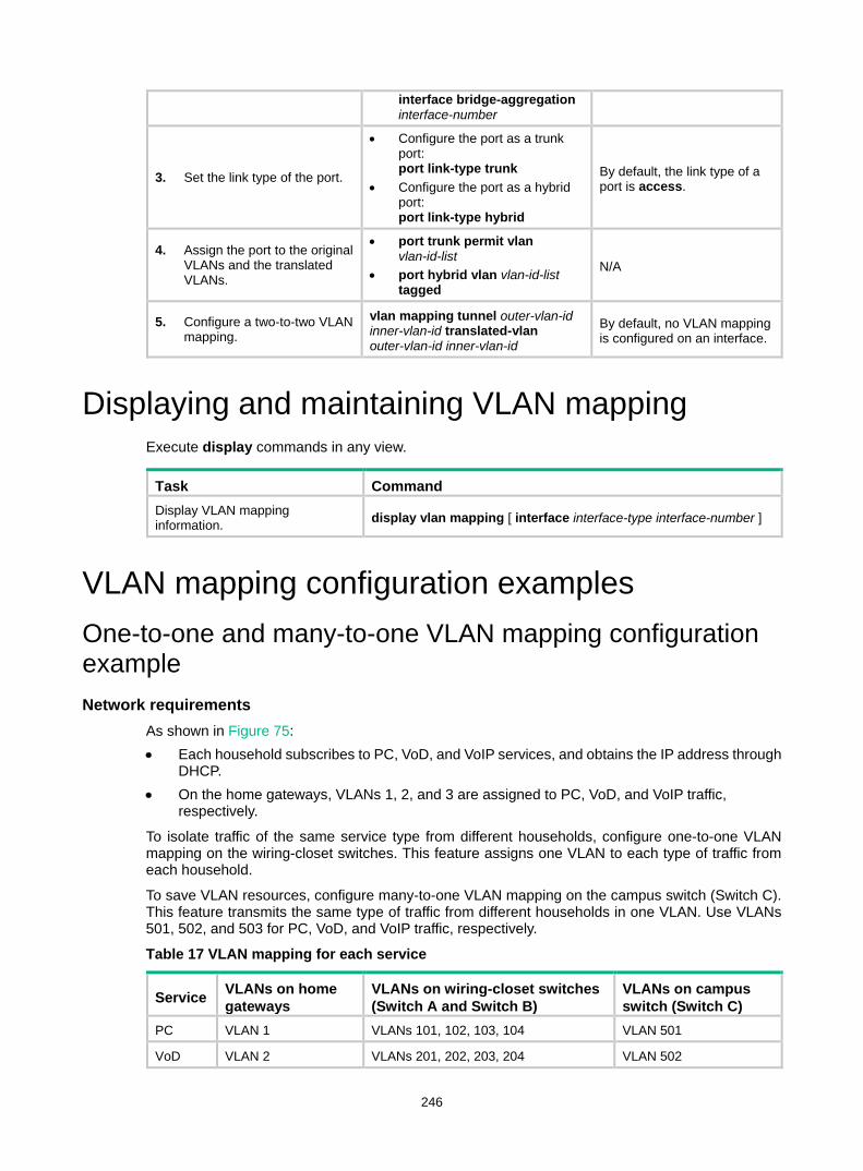
246
interface bridge-aggregation interface-number
3. Set the link type of the port.
• Configure the port as a trunk port: port link-type trunk
• Configure the port as a hybrid port: port link-type hybrid
By default, the link type of a port is access.
4. Assign the port to the original VLANs and the translated VLANs.
• port trunk permit vlan vlan-id-list
• port hybrid vlan vlan-id-list tagged
N/A
5. Configure a two-to-two VLAN mapping.
vlan mapping tunnel outer-vlan-id inner-vlan-id translated-vlan outer-vlan-id inner-vlan-id
By default, no VLAN mapping is configured on an interface.
Displaying and maintaining VLAN mapping Execute display commands in any view.
Task Command Display VLAN mapping information. display vlan mapping [ interface interface-type interface-number ]
VLAN mapping configuration examples One-to-one and many-to-one VLAN mapping configuration example Network requirements
As shown in Figure 75: • Each household subscribes to PC, VoD, and VoIP services, and obtains the IP address through
DHCP. • On the home gateways, VLANs 1, 2, and 3 are assigned to PC, VoD, and VoIP traffic,
respectively.
To isolate traffic of the same service type from different households, configure one-to-one VLAN mapping on the wiring-closet switches. This feature assigns one VLAN to each type of traffic from each household.
To save VLAN resources, configure many-to-one VLAN mapping on the campus switch (Switch C). This feature transmits the same type of traffic from different households in one VLAN. Use VLANs 501, 502, and 503 for PC, VoD, and VoIP traffic, respectively.
Table 17 VLAN mapping for each service
Service VLANs on home gateways
VLANs on wiring-closet switches (Switch A and Switch B)
VLANs on campus switch (Switch C)
PC VLAN 1 VLANs 101, 102, 103, 104 VLAN 501
VoD VLAN 2 VLANs 201, 202, 203, 204 VLAN 502
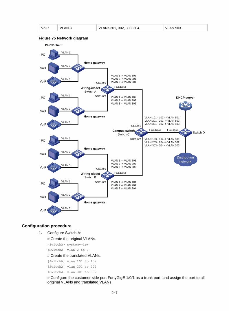
247
VoIP VLAN 3 VLANs 301, 302, 303, 304 VLAN 503
Figure 75 Network diagram
Configuration procedure 1. Configure Switch A:
# Create the original VLANs. <SwitchA> system-view
[SwitchA] vlan 2 to 3
# Create the translated VLANs. [SwitchA] vlan 101 to 102
[SwitchA] vlan 201 to 202
[SwitchA] vlan 301 to 302
# Configure the customer-side port FortyGigE 1/0/1 as a trunk port, and assign the port to all original VLANs and translated VLANs.
Campus switchSwitch C
Distribution network
DHCP client
DHCP server
Wiring-closetSwitch A
VLAN 1 -> VLAN 101VLAN 2 -> VLAN 201VLAN 3 -> VLAN 301
VLAN 1 -> VLAN 102VLAN 2 -> VLAN 202VLAN 3 -> VLAN 302
PC
VoD
VoIP
VLAN 2Home gateway
VLAN 1
VLAN 3
PC
VoD
VoIP
VLAN 2
Home gateway
VLAN 1
VLAN 3
VLAN 1 -> VLAN 103VLAN 2 -> VLAN 203VLAN 3 -> VLAN 303
VLAN 1 -> VLAN 104VLAN 2 -> VLAN 204VLAN 3 -> VLAN 304
PC
VoD
VoIP
VLAN 2Home gateway
VLAN 1
VLAN 3
PC
VoD
VoIP
VLAN 2
Home gateway
VLAN 1
VLAN 3
Wiring-closetSwitch B
FGE1/0/1
FGE1/0/2
FGE1/0/1
FGE1/0/2
FGE1/0/1
FGE1/0/2
FGE1/0/3
FGE1/0/3
FGE1/0/3
FGE1/0/1Switch D
VLAN 103 - 104 -> VLAN 501VLAN 203 - 204 -> VLAN 502VLAN 303 - 304 -> VLAN 503
VLAN 101 - 102 -> VLAN 501VLAN 201 - 202 -> VLAN 502VLAN 301 - 302 -> VLAN 503
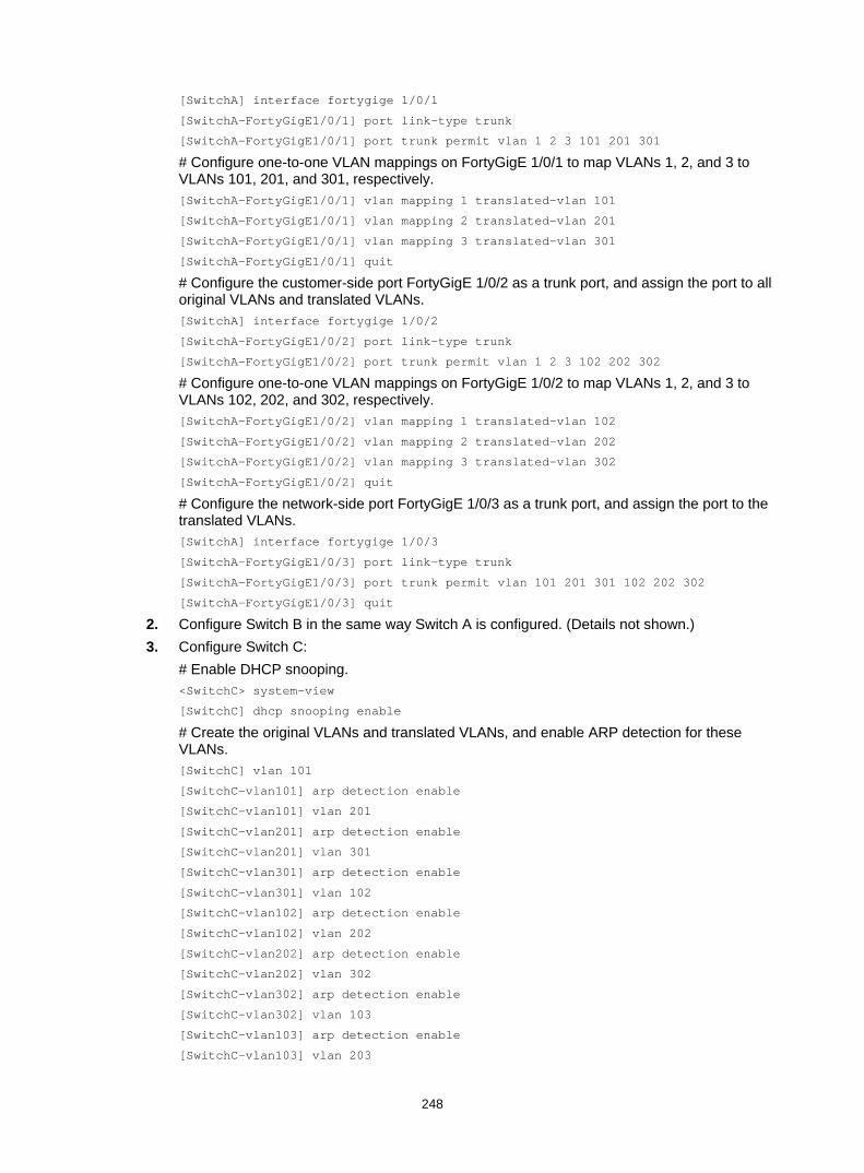
248
[SwitchA] interface fortygige 1/0/1
[SwitchA-FortyGigE1/0/1] port link-type trunk
[SwitchA-FortyGigE1/0/1] port trunk permit vlan 1 2 3 101 201 301
# Configure one-to-one VLAN mappings on FortyGigE 1/0/1 to map VLANs 1, 2, and 3 to VLANs 101, 201, and 301, respectively. [SwitchA-FortyGigE1/0/1] vlan mapping 1 translated-vlan 101
[SwitchA-FortyGigE1/0/1] vlan mapping 2 translated-vlan 201
[SwitchA-FortyGigE1/0/1] vlan mapping 3 translated-vlan 301
[SwitchA-FortyGigE1/0/1] quit
# Configure the customer-side port FortyGigE 1/0/2 as a trunk port, and assign the port to all original VLANs and translated VLANs. [SwitchA] interface fortygige 1/0/2
[SwitchA-FortyGigE1/0/2] port link-type trunk
[SwitchA-FortyGigE1/0/2] port trunk permit vlan 1 2 3 102 202 302
# Configure one-to-one VLAN mappings on FortyGigE 1/0/2 to map VLANs 1, 2, and 3 to VLANs 102, 202, and 302, respectively. [SwitchA-FortyGigE1/0/2] vlan mapping 1 translated-vlan 102
[SwitchA-FortyGigE1/0/2] vlan mapping 2 translated-vlan 202
[SwitchA-FortyGigE1/0/2] vlan mapping 3 translated-vlan 302
[SwitchA-FortyGigE1/0/2] quit
# Configure the network-side port FortyGigE 1/0/3 as a trunk port, and assign the port to the translated VLANs. [SwitchA] interface fortygige 1/0/3
[SwitchA-FortyGigE1/0/3] port link-type trunk
[SwitchA-FortyGigE1/0/3] port trunk permit vlan 101 201 301 102 202 302
[SwitchA-FortyGigE1/0/3] quit
2. Configure Switch B in the same way Switch A is configured. (Details not shown.) 3. Configure Switch C:
# Enable DHCP snooping. <SwitchC> system-view
[SwitchC] dhcp snooping enable
# Create the original VLANs and translated VLANs, and enable ARP detection for these VLANs. [SwitchC] vlan 101
[SwitchC-vlan101] arp detection enable
[SwitchC-vlan101] vlan 201
[SwitchC-vlan201] arp detection enable
[SwitchC-vlan201] vlan 301
[SwitchC-vlan301] arp detection enable
[SwitchC-vlan301] vlan 102
[SwitchC-vlan102] arp detection enable
[SwitchC-vlan102] vlan 202
[SwitchC-vlan202] arp detection enable
[SwitchC-vlan202] vlan 302
[SwitchC-vlan302] arp detection enable
[SwitchC-vlan302] vlan 103
[SwitchC-vlan103] arp detection enable
[SwitchC-vlan103] vlan 203

249
[SwitchC-vlan203] arp detection enable
[SwitchC-vlan203] vlan 303
[SwitchC-vlan303] arp detection enable
[SwitchC-vlan303] vlan 104
[SwitchC-vlan104] arp detection enable
[SwitchC-vlan104] vlan 204
[SwitchC-vlan204] arp detection enable
[SwitchC-vlan204] vlan 304
[SwitchC-vlan304] arp detection enable
[SwitchC-vlan304] vlan 501
[SwitchC-vlan501] arp detection enable
[SwitchC-vlan501] vlan 502
[SwitchC-vlan502] arp detection enable
[SwitchC-vlan502] vlan 503
[SwitchC-vlan503] arp detection enable
[SwitchC-vlan503] quit
# Configure the customer-side port FortyGigE 1/0/1 as a trunk port, and assign the port to original VLANs and translated VLANs. [SwitchC] interface fortygige 1/0/1
[SwitchC-FortyGigE1/0/1] port link-type trunk
[SwitchC-FortyGigE1/0/1] port trunk permit vlan 101 102 201 202 301 302 501 to 503
# Configure many-to-one VLAN mappings on the customer-side port FortyGigE 1/0/1 to map VLANs for PC, VoD, and VoIP traffic to VLANs 501, 502, and 503, respectively. [SwitchC-FortyGigE1/0/1] vlan mapping uni range 101 to 102 translated-vlan 501
[SwitchC-FortyGigE1/0/1] vlan mapping uni range 201 to 202 translated-vlan 502
[SwitchC-FortyGigE1/0/1] vlan mapping uni range 301 to 302 translated-vlan 503
# Enable DHCP snooping entry recording on FortyGigE 1/0/1. [SwitchC-FortyGigE1/0/1] dhcp snooping binding record
[SwitchC-FortyGigE1/0/1] quit
# Configure the customer-side port FortyGigE 1/0/2 as a trunk port, and assign the port to original VLANs and translated VLANs. [SwitchC] interface fortygige 1/0/2
[SwitchC-FortyGigE1/0/2] port link-type trunk
[SwitchC-FortyGigE1/0/2] port trunk permit vlan 103 104 203 204 303 304 501 to 503
# Configure many-to-one VLAN mappings on the customer-side port FortyGigE 1/0/2 to map VLANs for PC, VoD, and VoIP traffic to VLANs 501, 502, and 503, respectively. [SwitchC-FortyGigE1/0/2] vlan mapping uni range 103 to 104 translated-vlan 501
[SwitchC-FortyGigE1/0/2] vlan mapping uni range 203 to 204 translated-vlan 502
[SwitchC-FortyGigE1/0/2] vlan mapping uni range 303 to 304 translated-vlan 503
# Enable DHCP snooping entry recording on FortyGigE 1/0/2. [SwitchC-FortyGigE1/0/2] dhcp snooping binding record
[SwitchC-FortyGigE1/0/2] quit
# Configure the network-side port FortyGigE 1/0/3 to use the original VLAN tags of the many-to-one mappings to replace the VLAN tags of the packets destined for the user network. [SwitchC] interface fortygige 1/0/3
[SwitchC-FortyGigE1/0/3] vlan mapping nni
# Configure FortyGigE 1/0/3 as a trunk port, and assign the port to the translated VLANs. [SwitchC-FortyGigE1/0/3] port link-type trunk

250
[SwitchC-FortyGigE1/0/3] port trunk permit vlan 501 to 503
# Configure FortyGigE 1/0/3 as a DHCP snooping trusted and ARP trusted port. [SwitchC-FortyGigE1/0/3] dhcp snooping trust
[SwitchC-FortyGigE1/0/3] arp detection trust
[SwitchC-FortyGigE1/0/3] quit
4. Configure Switch D: # Create the translated VLANs. <SwitchD> system-view
[SwitchD] vlan 501 to 503
# Configure FortyGigE 1/0/1 as a trunk port, and assign the port to the translated VLANs 501 through 503. [SwitchD] interface fortygige 1/0/1
[SwitchD-FortyGigE1/0/1] port link-type trunk
[SwitchD-FortyGigE1/0/1] port trunk permit vlan 501 to 503
[SwitchD-FortyGigE1/0/1] quit
Verifying the configuration # Verify VLAN mapping information on the wiring-closet switches, for example, Switch A. [SwitchA] display vlan mapping
Interface FortyGigE1/0/1:
Outer VLAN Inner VLAN Translated Outer VLAN Translated Inner VLAN
1 N/A 101 N/A
2 N/A 201 N/A
3 N/A 301 N/A
Interface FortyGigE1/0/2:
Outer VLAN Inner VLAN Translated Outer VLAN Translated Inner VLAN
1 N/A 102 N/A
2 N/A 202 N/A
3 N/A 302 N/A
# Verify VLAN mapping information on Switch C. [SwitchC] display vlan mapping
Interface FortyGigE1/0/1:
Outer VLAN Inner VLAN Translated Outer VLAN Translated Inner VLAN
101-102 N/A 501 N/A
201-202 N/A 502 N/A
301-302 N/A 503 N/A
Interface FortyGigE1/0/2:
Outer VLAN Inner VLAN Translated Outer VLAN Translated Inner VLAN
103-104 N/A 501 N/A
203-204 N/A 502 N/A
303-304 N/A 503 N/A
One-to-two and two-to-two VLAN mapping configuration example Network requirements
As shown in Figure 76:
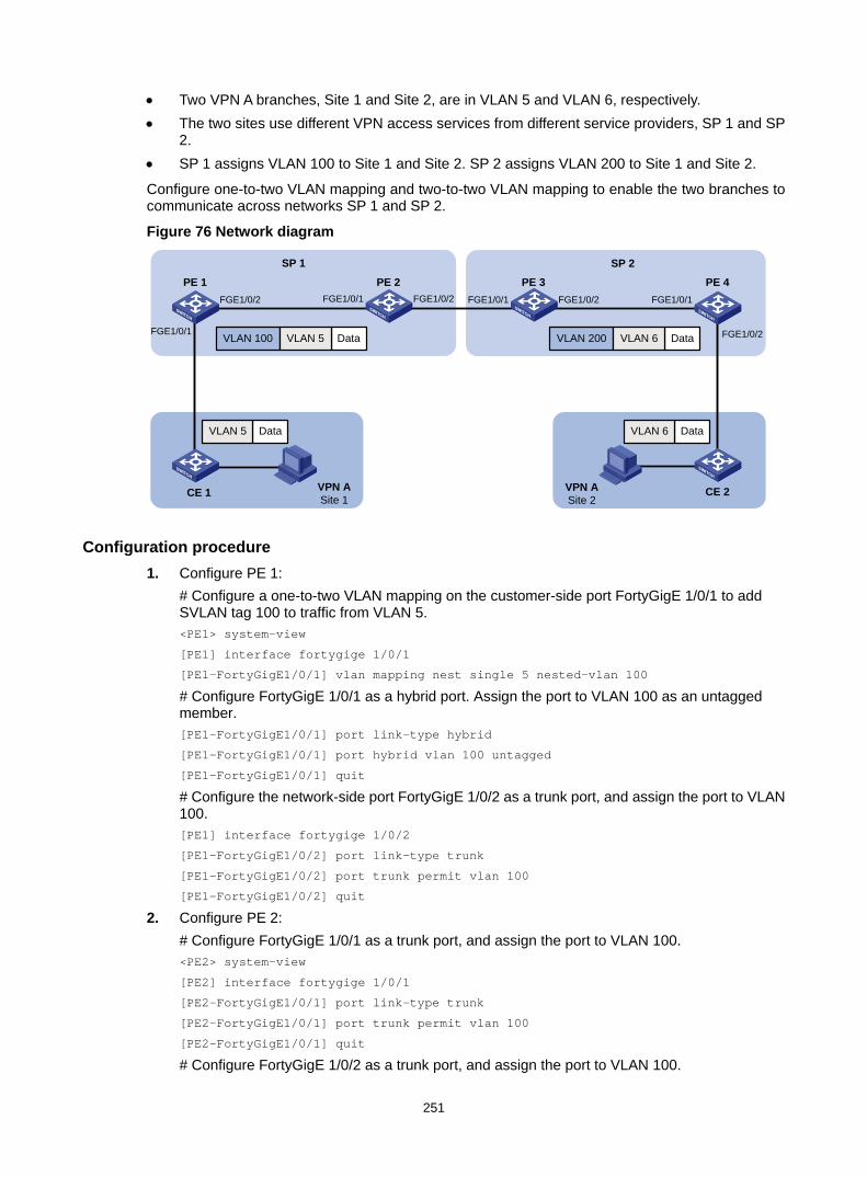
251
• Two VPN A branches, Site 1 and Site 2, are in VLAN 5 and VLAN 6, respectively. • The two sites use different VPN access services from different service providers, SP 1 and SP
2. • SP 1 assigns VLAN 100 to Site 1 and Site 2. SP 2 assigns VLAN 200 to Site 1 and Site 2.
Configure one-to-two VLAN mapping and two-to-two VLAN mapping to enable the two branches to communicate across networks SP 1 and SP 2.
Figure 76 Network diagram
Configuration procedure 1. Configure PE 1:
# Configure a one-to-two VLAN mapping on the customer-side port FortyGigE 1/0/1 to add SVLAN tag 100 to traffic from VLAN 5. <PE1> system-view
[PE1] interface fortygige 1/0/1
[PE1-FortyGigE1/0/1] vlan mapping nest single 5 nested-vlan 100
# Configure FortyGigE 1/0/1 as a hybrid port. Assign the port to VLAN 100 as an untagged member. [PE1-FortyGigE1/0/1] port link-type hybrid
[PE1-FortyGigE1/0/1] port hybrid vlan 100 untagged
[PE1-FortyGigE1/0/1] quit
# Configure the network-side port FortyGigE 1/0/2 as a trunk port, and assign the port to VLAN 100. [PE1] interface fortygige 1/0/2
[PE1-FortyGigE1/0/2] port link-type trunk
[PE1-FortyGigE1/0/2] port trunk permit vlan 100
[PE1-FortyGigE1/0/2] quit
2. Configure PE 2: # Configure FortyGigE 1/0/1 as a trunk port, and assign the port to VLAN 100. <PE2> system-view
[PE2] interface fortygige 1/0/1
[PE2-FortyGigE1/0/1] port link-type trunk
[PE2-FortyGigE1/0/1] port trunk permit vlan 100
[PE2-FortyGigE1/0/1] quit
# Configure FortyGigE 1/0/2 as a trunk port, and assign the port to VLAN 100.
PE 1
SP 1 SP 2PE 2 PE 3 PE 4
FGE1/0/1
FGE1/0/2 FGE1/0/1 FGE1/0/2 FGE1/0/1 FGE1/0/2 FGE1/0/1
FGE1/0/2
VPN ASite 1
CE 1 CE 2VPN ASite 2
DataVLAN 5
DataVLAN 100 VLAN 5 DataVLAN 200 VLAN 6
DataVLAN 6
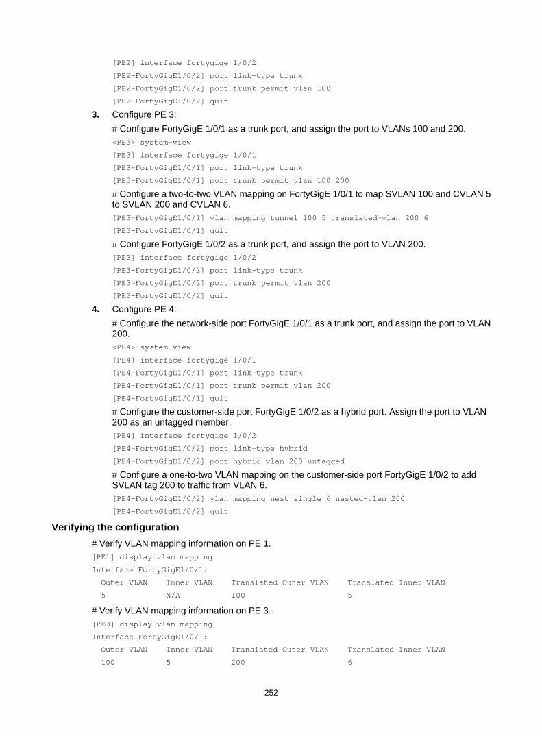
252
[PE2] interface fortygige 1/0/2
[PE2-FortyGigE1/0/2] port link-type trunk
[PE2-FortyGigE1/0/2] port trunk permit vlan 100
[PE2-FortyGigE1/0/2] quit
3. Configure PE 3: # Configure FortyGigE 1/0/1 as a trunk port, and assign the port to VLANs 100 and 200. <PE3> system-view
[PE3] interface fortygige 1/0/1
[PE3-FortyGigE1/0/1] port link-type trunk
[PE3-FortyGigE1/0/1] port trunk permit vlan 100 200
# Configure a two-to-two VLAN mapping on FortyGigE 1/0/1 to map SVLAN 100 and CVLAN 5 to SVLAN 200 and CVLAN 6. [PE3-FortyGigE1/0/1] vlan mapping tunnel 100 5 translated-vlan 200 6
[PE3-FortyGigE1/0/1] quit
# Configure FortyGigE 1/0/2 as a trunk port, and assign the port to VLAN 200. [PE3] interface fortygige 1/0/2
[PE3-FortyGigE1/0/2] port link-type trunk
[PE3-FortyGigE1/0/2] port trunk permit vlan 200
[PE3-FortyGigE1/0/2] quit
4. Configure PE 4: # Configure the network-side port FortyGigE 1/0/1 as a trunk port, and assign the port to VLAN 200. <PE4> system-view
[PE4] interface fortygige 1/0/1
[PE4-FortyGigE1/0/1] port link-type trunk
[PE4-FortyGigE1/0/1] port trunk permit vlan 200
[PE4-FortyGigE1/0/1] quit
# Configure the customer-side port FortyGigE 1/0/2 as a hybrid port. Assign the port to VLAN 200 as an untagged member. [PE4] interface fortygige 1/0/2
[PE4-FortyGigE1/0/2] port link-type hybrid
[PE4-FortyGigE1/0/2] port hybrid vlan 200 untagged
# Configure a one-to-two VLAN mapping on the customer-side port FortyGigE 1/0/2 to add SVLAN tag 200 to traffic from VLAN 6. [PE4-FortyGigE1/0/2] vlan mapping nest single 6 nested-vlan 200
[PE4-FortyGigE1/0/2] quit
Verifying the configuration # Verify VLAN mapping information on PE 1. [PE1] display vlan mapping
Interface FortyGigE1/0/1:
Outer VLAN Inner VLAN Translated Outer VLAN Translated Inner VLAN
5 N/A 100 5
# Verify VLAN mapping information on PE 3. [PE3] display vlan mapping
Interface FortyGigE1/0/1:
Outer VLAN Inner VLAN Translated Outer VLAN Translated Inner VLAN
100 5 200 6

253
# Verify VLAN mapping information on PE 4. [PE4] display vlan mapping
Interface FortyGigE1/0/2:
Outer VLAN Inner VLAN Translated Outer VLAN Translated Inner VLAN
6 N/A 200 6
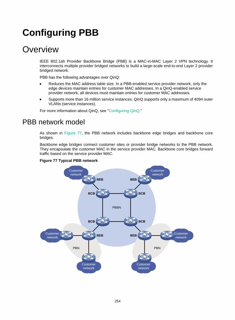
254
Configuring PBB Overview
IEEE 802.1ah Provider Backbone Bridge (PBB) is a MAC-in-MAC Layer 2 VPN technology. It interconnects multiple provider bridged networks to build a large-scale end-to-end Layer 2 provider bridged network.
PBB has the following advantages over QinQ: • Reduces the MAC address table size. In a PBB-enabled service provider network, only the
edge devices maintain entries for customer MAC addresses. In a QinQ-enabled service provider network, all devices must maintain entries for customer MAC addresses.
• Supports more than 16 million service instances. QinQ supports only a maximum of 4094 outer VLANs (service instances).
For more information about QinQ, see "Configuring QinQ."
PBB network model As shown in Figure 77, the PBB network includes backbone edge bridges and backbone core bridges.
Backbone edge bridges connect customer sites or provider bridge networks to the PBB network. They encapsulate the customer MAC in the service provider MAC. Backbone core bridges forward traffic based on the service provider MAC.
Figure 77 Typical PBB network
Customernetwork
Customernetwork
Customernetwork
Customernetwork
Customernetwork
Customernetwork
PBBN
PBN PBN
BCB BCB
BCBBCB
BEB BEB
BEB BEB

255
Terminology PBBN
A network using PBB is a provider backbone bridge network (PBBN). A PBBN is a Layer 2 switching network where Layer 2 connections are established between different nodes.
PBN A provider bridge network (PBN) connects a PBBN to a customer network. A customer network can connect to a PBBN directly or through a PBN.
BEB A backbone edge bridge (BEB) is an edge device in a PBBN. A BEB encapsulates frames from a customer network by using PBB. It decapsulates PBB frames from a PBBN and forwards them to a customer network. The BEB learns customer MAC addresses.
BCB A backbone core bridge (BCB) is a core device in a PBBN. It forwards a PBB frame according to its B-MAC and B-VLAN. A BCB only forwards frames and learns MAC addresses within the PBBN. It does not learn a large number of customer MAC addresses. This reduces network deployment costs, and the PBBN is more expandable.
B-MAC and B-VLAN A backbone MAC address (B-MAC) is a bridge MAC address associated with a PBB bridge. A backbone VLAN (B-VLAN) is a VLAN assigned by the service provider for transmitting customer traffic on the PBBN.
For customer frames to be transmitted across a PBBN, the ingress BEB encapsulates them in MAC-in-MAC format. In the outer frame header, the source MAC address is a B-MAC of the ingress BEB, and the destination MAC is a B-MAC of the egress BEB. All devices in the PBBN forward the PBB frames based on the destination B-MAC and B-VLAN.
Uplink port and downlink port A port that connects a BEB to a PBBN is an uplink port, and a port that connects a BEB to a customer network is a downlink port. After frames from the customer network are encapsulated in PBB frames, they are forwarded out of the corresponding uplink ports on the BEB. After PBB frames from the PBBN are decapsulated, they are forwarded out of the corresponding downlink ports on the BEB according to the customer MAC addresses.
PBB VSI and I-SID In a PBBN, a PBB VSI is a virtual switch provided by the service provider, and it is uniquely identified by a backbone service instance identifier (I-SID). A VSI acts as a virtual switch with all conventional Ethernet switch functions, including source MAC address learning, MAC address aging, and flooding.
PBB frame format Figure 78 shows the format of a PBB frame.

256
Figure 78 PBB frame format
Table 18 describes key fields in the frame.
Table 18 PBB frame fields
Field Full name Description
B-DA Backbone destination MAC address
Destination B-MAC, outer destination MAC address in a PBB frame. It is the MAC address of the BEB at the destination end of the PBBN tunnel. The combination of B-DA and B-SA is B-MAC.
B-SA Backbone source MAC address Source B-MAC, outer source MAC address in a PBB frame. It is the MAC address of the BEB at the source end of the PBBN tunnel. The combination of B-DA and B-SA is B-MAC.
B-Tag Backbone VLAN tag B-VLAN tag, outer VLAN tag in a PBB frame. It indicates the VLAN information and priority information of the frame within the PBBN. The TPID in a B-Tag is 0x8100.
I-Tag Backbone service instance tag
Service identifier of a PBB frame. The I-Tag contains the following fields: • TPID—The TPID in an I-Tag is 0x88E7. • I-PCP—Backbone service instance priority code point. • I-DEI—Backbone service instance drop eligibility
indicator. • I-SID—Backbone service instance identifier. • C-DA—Destination MAC address of the customer
frame. • C-SA—Source MAC address of the customer frame.
S-Tag Service provider VLAN tag Outer VLAN tag of the frame in the PBN, which indicates the VLAN and priority information of the frame within the PBN.
C-Tag Customer VLAN tag Inner VLAN tag of the frame in the PBN, which indicates the VLAN and priority information of the frame within the customer network.
For more information about TPID, see "Configuring VLANs."
B-Tag I-Tag Ethernet type Data
CFI B-VLANPRITPID
Res1UCA Res2I-PCP I-DEI I-SID C-DA C-SA
B-DA B-SA C-TagS-Tag
TPID
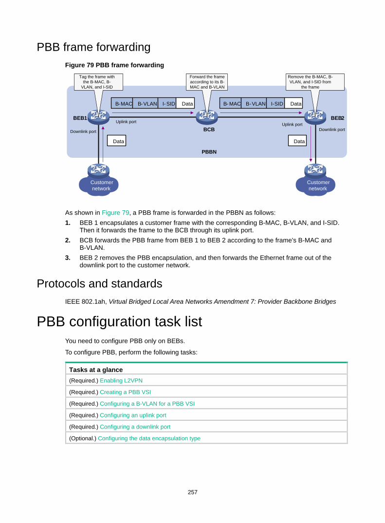
257
PBB frame forwarding Figure 79 PBB frame forwarding
As shown in Figure 79, a PBB frame is forwarded in the PBBN as follows: 1. BEB 1 encapsulates a customer frame with the corresponding B-MAC, B-VLAN, and I-SID.
Then it forwards the frame to the BCB through its uplink port. 2. BCB forwards the PBB frame from BEB 1 to BEB 2 according to the frame's B-MAC and
B-VLAN. 3. BEB 2 removes the PBB encapsulation, and then forwards the Ethernet frame out of the
downlink port to the customer network.
Protocols and standards IEEE 802.1ah, Virtual Bridged Local Area Networks Amendment 7: Provider Backbone Bridges
PBB configuration task list You need to configure PBB only on BEBs.
To configure PBB, perform the following tasks:
Tasks at a glance (Required.) Enabling L2VPN
(Required.) Creating a PBB VSI
(Required.) Configuring a B-VLAN for a PBB VSI
(Required.) Configuring an uplink port
(Required.) Configuring a downlink port
(Optional.) Configuring the data encapsulation type
Customernetwork
Customernetwork
BCB
BEB 1 BEB 2
PBBN
Forward the frame according to its B-MAC and B-VLAN
Uplink port
Downlink portUplink port
Downlink port
B-MAC B-VLAN DataI-SID B- MAC B-VLAN DataI-SID
Data Data
Tag the frame with the B-MAC, B-
VLAN, and I-SID
Remove the B-MAC, B-VLAN, and I-SID from
the frame
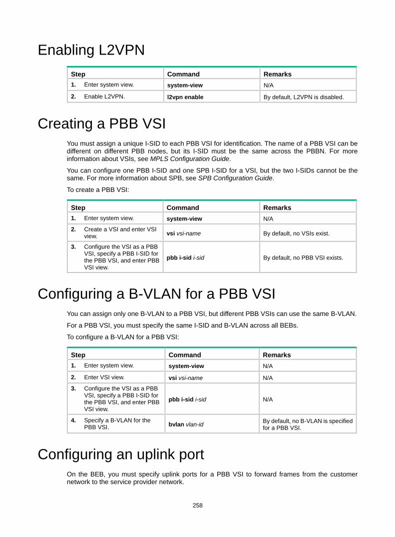
258
Enabling L2VPN Step Command Remarks 1. Enter system view. system-view N/A
2. Enable L2VPN. l2vpn enable By default, L2VPN is disabled.
Creating a PBB VSI You must assign a unique I-SID to each PBB VSI for identification. The name of a PBB VSI can be different on different PBB nodes, but its I-SID must be the same across the PBBN. For more information about VSIs, see MPLS Configuration Guide.
You can configure one PBB I-SID and one SPB I-SID for a VSI, but the two I-SIDs cannot be the same. For more information about SPB, see SPB Configuration Guide.
To create a PBB VSI:
Step Command Remarks 1. Enter system view. system-view N/A
2. Create a VSI and enter VSI view. vsi vsi-name By default, no VSIs exist.
3. Configure the VSI as a PBB VSI, specify a PBB I-SID for the PBB VSI, and enter PBB VSI view.
pbb i-sid i-sid By default, no PBB VSI exists.
Configuring a B-VLAN for a PBB VSI You can assign only one B-VLAN to a PBB VSI, but different PBB VSIs can use the same B-VLAN.
For a PBB VSI, you must specify the same I-SID and B-VLAN across all BEBs.
To configure a B-VLAN for a PBB VSI:
Step Command Remarks 1. Enter system view. system-view N/A
2. Enter VSI view. vsi vsi-name N/A
3. Configure the VSI as a PBB VSI, specify a PBB I-SID for the PBB VSI, and enter PBB VSI view.
pbb i-sid i-sid N/A
4. Specify a B-VLAN for the PBB VSI. bvlan vlan-id By default, no B-VLAN is specified
for a PBB VSI.
Configuring an uplink port On the BEB, you must specify uplink ports for a PBB VSI to forward frames from the customer network to the service provider network.
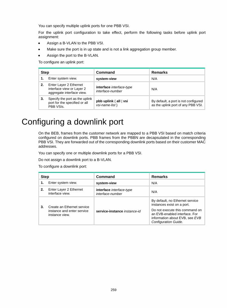
259
You can specify multiple uplink ports for one PBB VSI.
For the uplink port configuration to take effect, perform the following tasks before uplink port assignment: • Assign a B-VLAN to the PBB VSI. • Make sure the port is in up state and is not a link aggregation group member. • Assign the port to the B-VLAN.
To configure an uplink port:
Step Command Remarks 1. Enter system view. system-view N/A
2. Enter Layer 2 Ethernet interface view or Layer 2 aggregate interface view.
interface interface-type interface-number N/A
3. Specify the port as the uplink port for the specified or all PBB VSIs.
pbb uplink { all | vsi vsi-name-list }
By default, a port is not configured as the uplink port of any PBB VSI.
Configuring a downlink port On the BEB, frames from the customer network are mapped to a PBB VSI based on match criteria configured on downlink ports. PBB frames from the PBBN are decapsulated in the corresponding PBB VSI. They are forwarded out of the corresponding downlink ports based on their customer MAC addresses.
You can specify one or multiple downlink ports for a PBB VSI.
Do not assign a downlink port to a B-VLAN.
To configure a downlink port:
Step Command Remarks 1. Enter system view. system-view N/A
2. Enter Layer 2 Ethernet interface view.
interface interface-type interface-number N/A
3. Create an Ethernet service instance and enter service instance view.
service-instance instance-id
By default, no Ethernet service instances exist on a port. Do not execute this command on an EVB-enabled interface. For information about EVB, see EVB Configuration Guide.
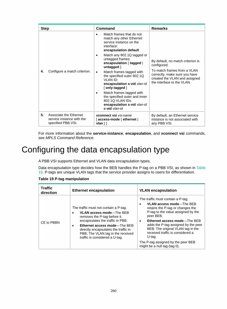
260
Step Command Remarks
4. Configure a match criterion.
• Match frames that do not match any other Ethernet service instance on the interface: encapsulation default
• Match any 802.1Q tagged or untagged frames: encapsulation { tagged | untagged }
• Match frames tagged with the specified outer 802.1Q VLAN ID: encapsulation s-vid vlan-id [ only-tagged ]
• Match frames tagged with the specified outer and inner 802.1Q VLAN IDs: encapsulation s-vid vlan-id c-vid vlan-id
By default, no match criterion is configured. To match frames from a VLAN correctly, make sure you have created the VLAN and assigned the interface to the VLAN.
5. Associate the Ethernet service instance with the specified PBB VSI.
xconnect vsi vsi-name [ access-mode { ethernet | vlan } ]
By default, an Ethernet service instance is not associated with any PBB VSI.
For more information about the service-instance, encapsulation, and xconnect vsi commands, see MPLS Command Reference.
Configuring the data encapsulation type A PBB VSI supports Ethernet and VLAN data encapsulation types.
Data encapsulation type decides how the BEB handles the P-tag on a PBB VSI, as shown in Table 19. P-tags are unique VLAN tags that the service provider assigns to users for differentiation.
Table 19 P-tag manipulation
Traffic direction Ethernet encapsulation VLAN encapsulation
CE to PBBN
The traffic must not contain a P-tag. • VLAN access mode—The BEB
removes the P-tag before it encapsulates the traffic in PBB.
• Ethernet access mode—The BEB directly encapsulates the traffic in PBB. The VLAN tag in the received traffic is considered a U-tag.
The traffic must contain a P-tag. • VLAN access mode—The BEB
retains the P-tag or changes the P-tag to the value assigned by the peer BEB.
• Ethernet access mode—The BEB adds the P-tag assigned by the peer BEB. The original VLAN tag in the received traffic is considered a U-tag.
The P-tag assigned by the peer BEB might be a null tag (tag 0).
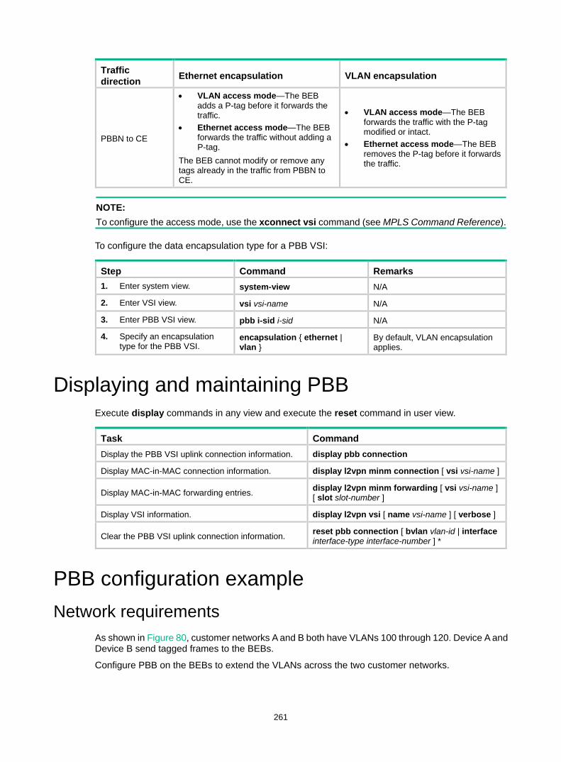
261
Traffic direction Ethernet encapsulation VLAN encapsulation
PBBN to CE
• VLAN access mode—The BEB adds a P-tag before it forwards the traffic.
• Ethernet access mode—The BEB forwards the traffic without adding a P-tag.
The BEB cannot modify or remove any tags already in the traffic from PBBN to CE.
• VLAN access mode—The BEB forwards the traffic with the P-tag modified or intact.
• Ethernet access mode—The BEB removes the P-tag before it forwards the traffic.
NOTE: To configure the access mode, use the xconnect vsi command (see MPLS Command Reference).
To configure the data encapsulation type for a PBB VSI:
Step Command Remarks 1. Enter system view. system-view N/A
2. Enter VSI view. vsi vsi-name N/A
3. Enter PBB VSI view. pbb i-sid i-sid N/A
4. Specify an encapsulation type for the PBB VSI.
encapsulation { ethernet | vlan }
By default, VLAN encapsulation applies.
Displaying and maintaining PBB Execute display commands in any view and execute the reset command in user view.
Task Command Display the PBB VSI uplink connection information. display pbb connection
Display MAC-in-MAC connection information. display l2vpn minm connection [ vsi vsi-name ]
Display MAC-in-MAC forwarding entries. display l2vpn minm forwarding [ vsi vsi-name ] [ slot slot-number ]
Display VSI information. display l2vpn vsi [ name vsi-name ] [ verbose ]
Clear the PBB VSI uplink connection information. reset pbb connection [ bvlan vlan-id | interface interface-type interface-number ] *
PBB configuration example Network requirements
As shown in Figure 80, customer networks A and B both have VLANs 100 through 120. Device A and Device B send tagged frames to the BEBs.
Configure PBB on the BEBs to extend the VLANs across the two customer networks.
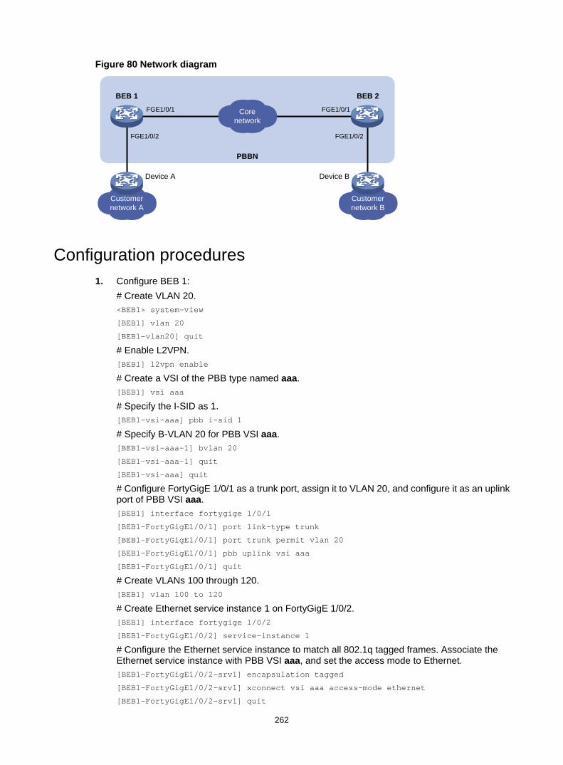
262
Figure 80 Network diagram
Configuration procedures 1. Configure BEB 1:
# Create VLAN 20. <BEB1> system-view
[BEB1] vlan 20
[BEB1-vlan20] quit
# Enable L2VPN. [BEB1] l2vpn enable
# Create a VSI of the PBB type named aaa. [BEB1] vsi aaa
# Specify the I-SID as 1. [BEB1-vsi-aaa] pbb i-sid 1
# Specify B-VLAN 20 for PBB VSI aaa. [BEB1-vsi-aaa-1] bvlan 20
[BEB1-vsi-aaa-1] quit
[BEB1-vsi-aaa] quit
# Configure FortyGigE 1/0/1 as a trunk port, assign it to VLAN 20, and configure it as an uplink port of PBB VSI aaa. [BEB1] interface fortygige 1/0/1
[BEB1-FortyGigE1/0/1] port link-type trunk
[BEB1-FortyGigE1/0/1] port trunk permit vlan 20
[BEB1-FortyGigE1/0/1] pbb uplink vsi aaa
[BEB1-FortyGigE1/0/1] quit
# Create VLANs 100 through 120. [BEB1] vlan 100 to 120
# Create Ethernet service instance 1 on FortyGigE 1/0/2. [BEB1] interface fortygige 1/0/2
[BEB1-FortyGigE1/0/2] service-instance 1
# Configure the Ethernet service instance to match all 802.1q tagged frames. Associate the Ethernet service instance with PBB VSI aaa, and set the access mode to Ethernet. [BEB1-FortyGigE1/0/2-srv1] encapsulation tagged
[BEB1-FortyGigE1/0/2-srv1] xconnect vsi aaa access-mode ethernet
[BEB1-FortyGigE1/0/2-srv1] quit
Customernetwork A
Corenetwork
Customernetwork B
FGE1/0/1 FGE1/0/1
FGE1/0/2 FGE1/0/2
PBBN
BEB 1 BEB 2
Device A Device B

263
[BEB1-FortyGigE1/0/2] quit
# Configure Ethernet encapsulation for the PBB VSI. [BEB1] vsi aaa
[BEB1-vsi-aaa] pbb i-sid 1
[BEB1-vsi-aaa-1] encapsulation ethernet
[BEB1-vsi-aaa-1] quit
2. Configure BEB 2 in the same way BEB 1 is configured. (Details not shown.)
Verifying the configuration # Display PBB VSI uplink connection information on BEB 1. [BEB1] display pbb connection
BMAC BVLAN Port Type Aging
011e-8300-0001 20 FGE1/0/1 MC N
000f-e200-0001 20 FGE1/0/1 UC Y
# Verify that Device A and Device B can ping each other. (Details not shown.)
Troubleshooting Symptom
Customer frames cannot be transmitted to the peer network by using PBB.
Analysis • No PBB VSI is configured on the BEB, or the configured VSI is down. • PBB configurations on the BEBs are inconsistent. • The B-VLAN in the BEB is not created on the BCB, or ports connecting the BEB and BCB are
not both assigned to the B-VLAN.
Solution To resolve the problem: 1. Use the display l2vpn vsi verbose command to display the PBB configuration of the VSI.
If the VSI is not configured as a PBB VSI, configure the VSI as a PBB VSI. If the VSI is down, use the undo shutdown command to bring the VSI up. For more information about the display l2vpn vsi verbose command, see MPLS Command Reference.
2. Use the display l2vpn vsi verbose command to verify that the VSI's PBB settings are consistent across BEBs, especially the I-SID and B-VLAN settings.
3. Use the display vlan all command to verify that the following settings are configured on all BCBs: The B-VLAN is created on each BCB. All ports on the path between the BEBs are assigned to the B-VLAN.
4. If the problem persists, contact H3C Support.
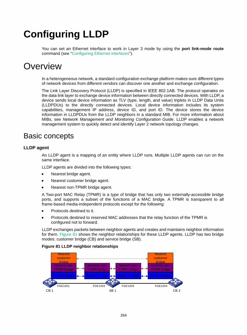
264
Configuring LLDP You can set an Ethernet interface to work in Layer 3 mode by using the port link-mode route command (see "Configuring Ethernet interfaces").
Overview In a heterogeneous network, a standard configuration exchange platform makes sure different types of network devices from different vendors can discover one another and exchange configuration.
The Link Layer Discovery Protocol (LLDP) is specified in IEEE 802.1AB. The protocol operates on the data link layer to exchange device information between directly connected devices. With LLDP, a device sends local device information as TLV (type, length, and value) triplets in LLDP Data Units (LLDPDUs) to the directly connected devices. Local device information includes its system capabilities, management IP address, device ID, and port ID. The device stores the device information in LLDPDUs from the LLDP neighbors in a standard MIB. For more information about MIBs, see Network Management and Monitoring Configuration Guide. LLDP enables a network management system to quickly detect and identify Layer 2 network topology changes.
Basic concepts LLDP agent
An LLDP agent is a mapping of an entity where LLDP runs. Multiple LLDP agents can run on the same interface.
LLDP agents are divided into the following types: • Nearest bridge agent. • Nearest customer bridge agent. • Nearest non-TPMR bridge agent.
A Two-port MAC Relay (TPMR) is a type of bridge that has only two externally-accessible bridge ports, and supports a subset of the functions of a MAC bridge. A TPMR is transparent to all frame-based media-independent protocols except for the following: • Protocols destined to it. • Protocols destined to reserved MAC addresses that the relay function of the TPMR is
configured not to forward.
LLDP exchanges packets between neighbor agents and creates and maintains neighbor information for them. Figure 81 shows the neighbor relationships for these LLDP agents. LLDP has two bridge modes: customer bridge (CB) and service bridge (SB).
Figure 81 LLDP neighbor relationships
FGE1/0/2 FGE1/0/3CB 1 SB 1 CB 2
FGE1/0/4FGE1/0/1
Nearest customer
bridge
Nearest customer
bridgeNearest non-TPMR bridge
Nearest bridge
Nearest non-TPMR bridge
Nearest bridge
Nearest non-TPMR bridge
Nearest bridge
Nearest non-TPMR bridge
Nearest bridge
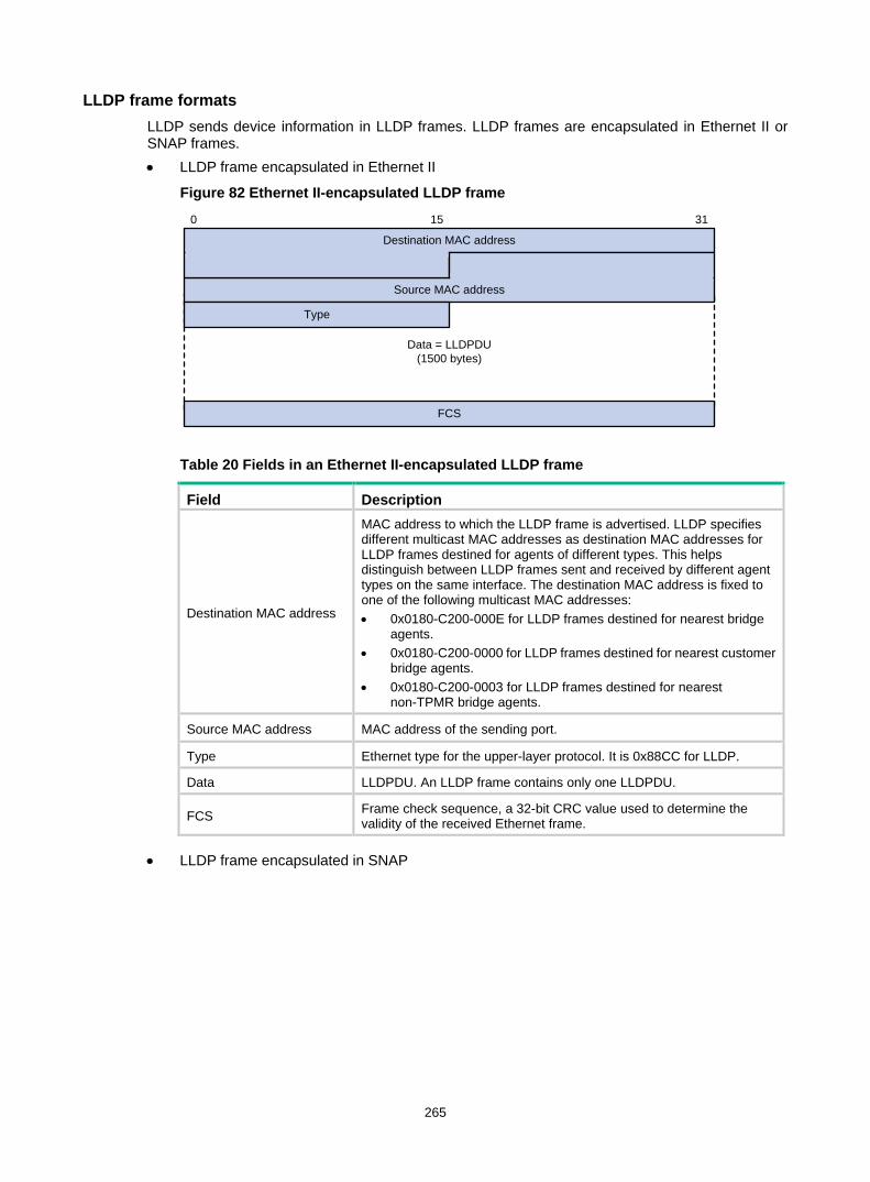
265
LLDP frame formats LLDP sends device information in LLDP frames. LLDP frames are encapsulated in Ethernet II or SNAP frames. • LLDP frame encapsulated in Ethernet II
Figure 82 Ethernet II-encapsulated LLDP frame
Table 20 Fields in an Ethernet II-encapsulated LLDP frame
Field Description
Destination MAC address
MAC address to which the LLDP frame is advertised. LLDP specifies different multicast MAC addresses as destination MAC addresses for LLDP frames destined for agents of different types. This helps distinguish between LLDP frames sent and received by different agent types on the same interface. The destination MAC address is fixed to one of the following multicast MAC addresses: • 0x0180-C200-000E for LLDP frames destined for nearest bridge
agents. • 0x0180-C200-0000 for LLDP frames destined for nearest customer
bridge agents. • 0x0180-C200-0003 for LLDP frames destined for nearest
non-TPMR bridge agents.
Source MAC address MAC address of the sending port.
Type Ethernet type for the upper-layer protocol. It is 0x88CC for LLDP.
Data LLDPDU. An LLDP frame contains only one LLDPDU.
FCS Frame check sequence, a 32-bit CRC value used to determine the validity of the received Ethernet frame.
• LLDP frame encapsulated in SNAP
Data = LLDPDU(1500 bytes)
0
Destination MAC address
Source MAC address
Type
15 31
FCS
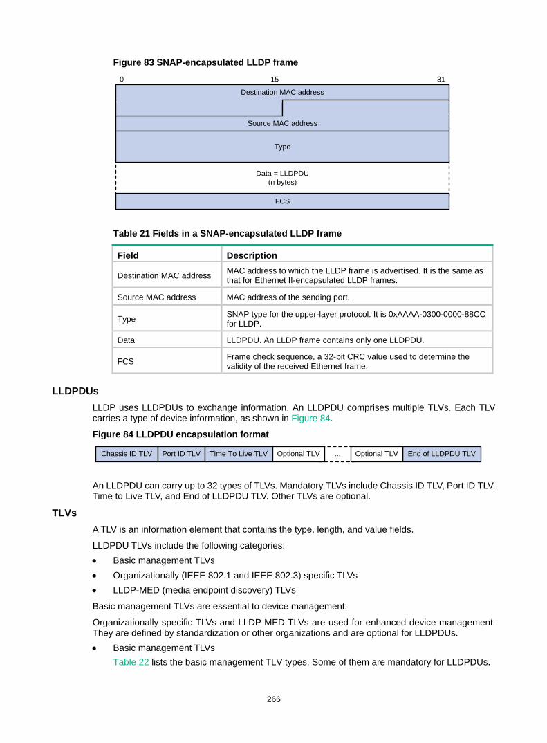
266
Figure 83 SNAP-encapsulated LLDP frame
Table 21 Fields in a SNAP-encapsulated LLDP frame
Field Description Destination MAC address MAC address to which the LLDP frame is advertised. It is the same as
that for Ethernet II-encapsulated LLDP frames.
Source MAC address MAC address of the sending port.
Type SNAP type for the upper-layer protocol. It is 0xAAAA-0300-0000-88CC for LLDP.
Data LLDPDU. An LLDP frame contains only one LLDPDU.
FCS Frame check sequence, a 32-bit CRC value used to determine the validity of the received Ethernet frame.
LLDPDUs LLDP uses LLDPDUs to exchange information. An LLDPDU comprises multiple TLVs. Each TLV carries a type of device information, as shown in Figure 84.
Figure 84 LLDPDU encapsulation format
An LLDPDU can carry up to 32 types of TLVs. Mandatory TLVs include Chassis ID TLV, Port ID TLV, Time to Live TLV, and End of LLDPDU TLV. Other TLVs are optional.
TLVs A TLV is an information element that contains the type, length, and value fields.
LLDPDU TLVs include the following categories: • Basic management TLVs • Organizationally (IEEE 802.1 and IEEE 802.3) specific TLVs • LLDP-MED (media endpoint discovery) TLVs
Basic management TLVs are essential to device management.
Organizationally specific TLVs and LLDP-MED TLVs are used for enhanced device management. They are defined by standardization or other organizations and are optional for LLDPDUs. • Basic management TLVs
Table 22 lists the basic management TLV types. Some of them are mandatory for LLDPDUs.
Data = LLDPDU(n bytes)
0
Destination MAC address
Source MAC address
Type
15 31
FCS
Chassis ID TLV Port ID TLV Time To Live TLV End of LLDPDU TLV...Optional TLV Optional TLV
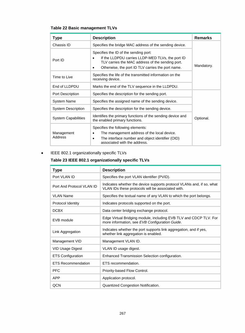
267
Table 22 Basic management TLVs
Type Description Remarks Chassis ID Specifies the bridge MAC address of the sending device.
Mandatory. Port ID
Specifies the ID of the sending port: • If the LLDPDU carries LLDP-MED TLVs, the port ID
TLV carries the MAC address of the sending port. • Otherwise, the port ID TLV carries the port name.
Time to Live Specifies the life of the transmitted information on the receiving device.
End of LLDPDU Marks the end of the TLV sequence in the LLDPDU.
Port Description Specifies the description for the sending port.
Optional.
System Name Specifies the assigned name of the sending device.
System Description Specifies the description for the sending device.
System Capabilities Identifies the primary functions of the sending device and the enabled primary functions.
Management Address
Specifies the following elements: • The management address of the local device. • The interface number and object identifier (OID)
associated with the address.
• IEEE 802.1 organizationally specific TLVs
Table 23 IEEE 802.1 organizationally specific TLVs
Type Description Port VLAN ID Specifies the port VLAN identifier (PVID).
Port And Protocol VLAN ID Indicates whether the device supports protocol VLANs and, if so, what VLAN IDs these protocols will be associated with.
VLAN Name Specifies the textual name of any VLAN to which the port belongs.
Protocol Identity Indicates protocols supported on the port.
DCBX Data center bridging exchange protocol.
EVB module Edge Virtual Bridging module, including EVB TLV and CDCP TLV. For more information, see EVB Configuration Guide.
Link Aggregation Indicates whether the port supports link aggregation, and if yes, whether link aggregation is enabled.
Management VID Management VLAN ID.
VID Usage Digest VLAN ID usage digest.
ETS Configuration Enhanced Transmission Selection configuration.
ETS Recommendation ETS recommendation.
PFC Priority-based Flow Control.
APP Application protocol.
QCN Quantized Congestion Notification.
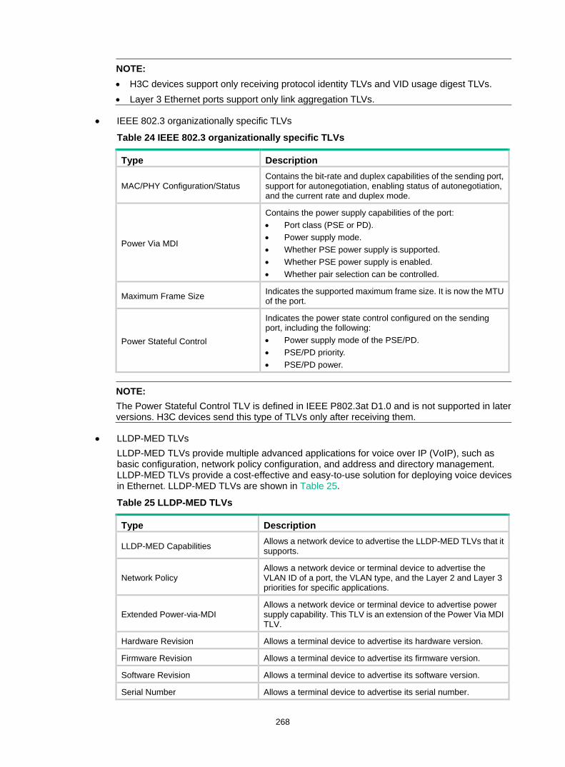
268
NOTE: • H3C devices support only receiving protocol identity TLVs and VID usage digest TLVs. • Layer 3 Ethernet ports support only link aggregation TLVs.
• IEEE 802.3 organizationally specific TLVs
Table 24 IEEE 802.3 organizationally specific TLVs
Type Description
MAC/PHY Configuration/Status Contains the bit-rate and duplex capabilities of the sending port, support for autonegotiation, enabling status of autonegotiation, and the current rate and duplex mode.
Power Via MDI
Contains the power supply capabilities of the port: • Port class (PSE or PD). • Power supply mode. • Whether PSE power supply is supported. • Whether PSE power supply is enabled. • Whether pair selection can be controlled.
Maximum Frame Size Indicates the supported maximum frame size. It is now the MTU of the port.
Power Stateful Control
Indicates the power state control configured on the sending port, including the following: • Power supply mode of the PSE/PD. • PSE/PD priority. • PSE/PD power.
NOTE: The Power Stateful Control TLV is defined in IEEE P802.3at D1.0 and is not supported in later versions. H3C devices send this type of TLVs only after receiving them.
• LLDP-MED TLVs LLDP-MED TLVs provide multiple advanced applications for voice over IP (VoIP), such as basic configuration, network policy configuration, and address and directory management. LLDP-MED TLVs provide a cost-effective and easy-to-use solution for deploying voice devices in Ethernet. LLDP-MED TLVs are shown in Table 25.
Table 25 LLDP-MED TLVs
Type Description
LLDP-MED Capabilities Allows a network device to advertise the LLDP-MED TLVs that it supports.
Network Policy Allows a network device or terminal device to advertise the VLAN ID of a port, the VLAN type, and the Layer 2 and Layer 3 priorities for specific applications.
Extended Power-via-MDI Allows a network device or terminal device to advertise power supply capability. This TLV is an extension of the Power Via MDI TLV.
Hardware Revision Allows a terminal device to advertise its hardware version.
Firmware Revision Allows a terminal device to advertise its firmware version.
Software Revision Allows a terminal device to advertise its software version.
Serial Number Allows a terminal device to advertise its serial number.
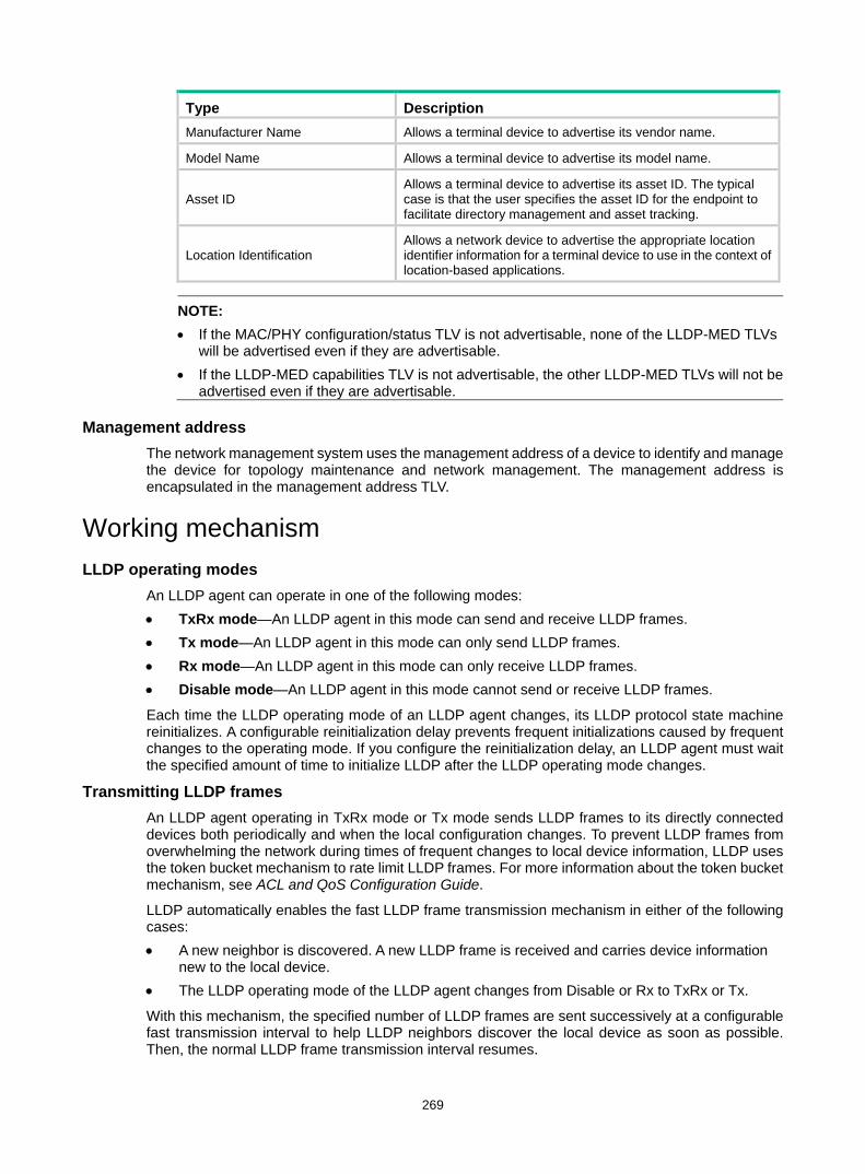
269
Type Description Manufacturer Name Allows a terminal device to advertise its vendor name.
Model Name Allows a terminal device to advertise its model name.
Asset ID Allows a terminal device to advertise its asset ID. The typical case is that the user specifies the asset ID for the endpoint to facilitate directory management and asset tracking.
Location Identification Allows a network device to advertise the appropriate location identifier information for a terminal device to use in the context of location-based applications.
NOTE: • If the MAC/PHY configuration/status TLV is not advertisable, none of the LLDP-MED TLVs
will be advertised even if they are advertisable. • If the LLDP-MED capabilities TLV is not advertisable, the other LLDP-MED TLVs will not be
advertised even if they are advertisable.
Management address The network management system uses the management address of a device to identify and manage the device for topology maintenance and network management. The management address is encapsulated in the management address TLV.
Working mechanism LLDP operating modes
An LLDP agent can operate in one of the following modes: • TxRx mode—An LLDP agent in this mode can send and receive LLDP frames. • Tx mode—An LLDP agent in this mode can only send LLDP frames. • Rx mode—An LLDP agent in this mode can only receive LLDP frames. • Disable mode—An LLDP agent in this mode cannot send or receive LLDP frames.
Each time the LLDP operating mode of an LLDP agent changes, its LLDP protocol state machine reinitializes. A configurable reinitialization delay prevents frequent initializations caused by frequent changes to the operating mode. If you configure the reinitialization delay, an LLDP agent must wait the specified amount of time to initialize LLDP after the LLDP operating mode changes.
Transmitting LLDP frames An LLDP agent operating in TxRx mode or Tx mode sends LLDP frames to its directly connected devices both periodically and when the local configuration changes. To prevent LLDP frames from overwhelming the network during times of frequent changes to local device information, LLDP uses the token bucket mechanism to rate limit LLDP frames. For more information about the token bucket mechanism, see ACL and QoS Configuration Guide.
LLDP automatically enables the fast LLDP frame transmission mechanism in either of the following cases: • A new neighbor is discovered. A new LLDP frame is received and carries device information
new to the local device. • The LLDP operating mode of the LLDP agent changes from Disable or Rx to TxRx or Tx.
With this mechanism, the specified number of LLDP frames are sent successively at a configurable fast transmission interval to help LLDP neighbors discover the local device as soon as possible. Then, the normal LLDP frame transmission interval resumes.
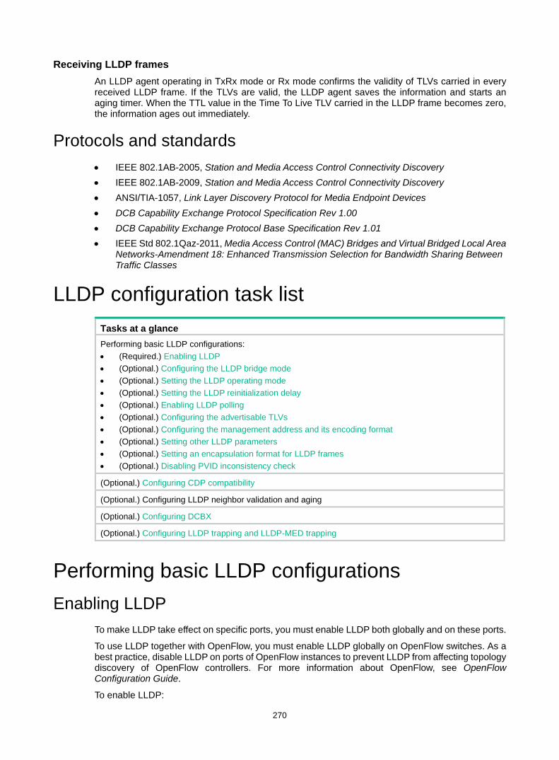
270
Receiving LLDP frames An LLDP agent operating in TxRx mode or Rx mode confirms the validity of TLVs carried in every received LLDP frame. If the TLVs are valid, the LLDP agent saves the information and starts an aging timer. When the TTL value in the Time To Live TLV carried in the LLDP frame becomes zero, the information ages out immediately.
Protocols and standards • IEEE 802.1AB-2005, Station and Media Access Control Connectivity Discovery • IEEE 802.1AB-2009, Station and Media Access Control Connectivity Discovery • ANSI/TIA-1057, Link Layer Discovery Protocol for Media Endpoint Devices • DCB Capability Exchange Protocol Specification Rev 1.00 • DCB Capability Exchange Protocol Base Specification Rev 1.01 • IEEE Std 802.1Qaz-2011, Media Access Control (MAC) Bridges and Virtual Bridged Local Area
Networks-Amendment 18: Enhanced Transmission Selection for Bandwidth Sharing Between Traffic Classes
LLDP configuration task list Tasks at a glance Performing basic LLDP configurations: • (Required.) Enabling LLDP • (Optional.) Configuring the LLDP bridge mode • (Optional.) Setting the LLDP operating mode • (Optional.) Setting the LLDP reinitialization delay • (Optional.) Enabling LLDP polling • (Optional.) Configuring the advertisable TLVs • (Optional.) Configuring the management address and its encoding format • (Optional.) Setting other LLDP parameters • (Optional.) Setting an encapsulation format for LLDP frames • (Optional.) Disabling PVID inconsistency check
(Optional.) Configuring CDP compatibility
(Optional.) Configuring LLDP neighbor validation and aging
(Optional.) Configuring DCBX
(Optional.) Configuring LLDP trapping and LLDP-MED trapping
Performing basic LLDP configurations Enabling LLDP
To make LLDP take effect on specific ports, you must enable LLDP both globally and on these ports.
To use LLDP together with OpenFlow, you must enable LLDP globally on OpenFlow switches. As a best practice, disable LLDP on ports of OpenFlow instances to prevent LLDP from affecting topology discovery of OpenFlow controllers. For more information about OpenFlow, see OpenFlow Configuration Guide.
To enable LLDP:
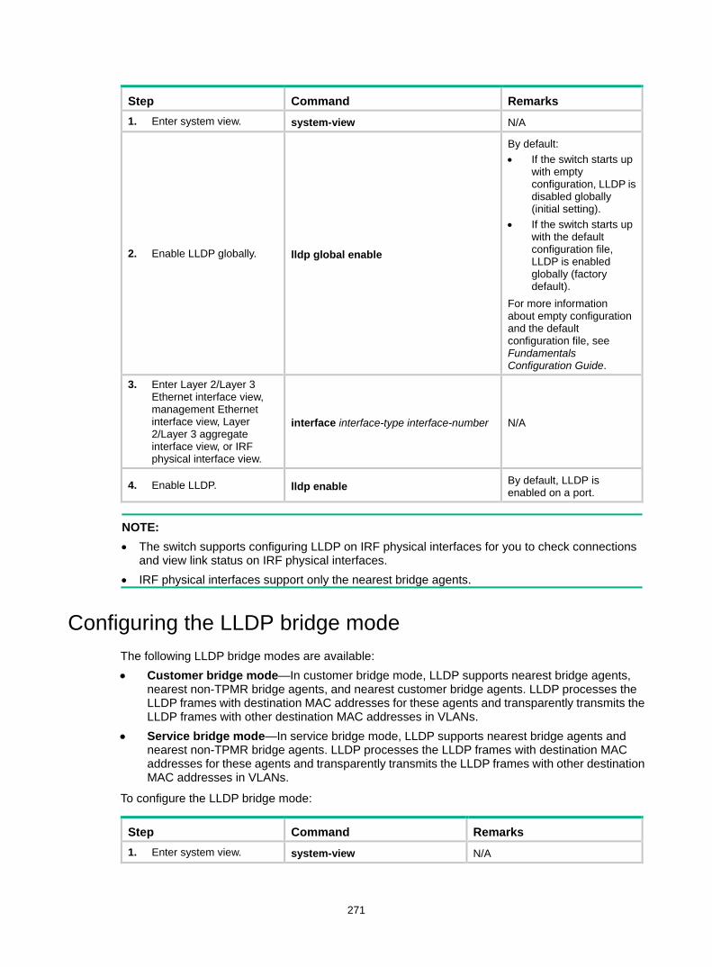
271
Step Command Remarks 1. Enter system view. system-view N/A
2. Enable LLDP globally. lldp global enable
By default: • If the switch starts up
with empty configuration, LLDP is disabled globally (initial setting).
• If the switch starts up with the default configuration file, LLDP is enabled globally (factory default).
For more information about empty configuration and the default configuration file, see Fundamentals Configuration Guide.
3. Enter Layer 2/Layer 3 Ethernet interface view, management Ethernet interface view, Layer 2/Layer 3 aggregate interface view, or IRF physical interface view.
interface interface-type interface-number N/A
4. Enable LLDP. lldp enable By default, LLDP is enabled on a port.
NOTE: • The switch supports configuring LLDP on IRF physical interfaces for you to check connections
and view link status on IRF physical interfaces. • IRF physical interfaces support only the nearest bridge agents.
Configuring the LLDP bridge mode The following LLDP bridge modes are available: • Customer bridge mode—In customer bridge mode, LLDP supports nearest bridge agents,
nearest non-TPMR bridge agents, and nearest customer bridge agents. LLDP processes the LLDP frames with destination MAC addresses for these agents and transparently transmits the LLDP frames with other destination MAC addresses in VLANs.
• Service bridge mode—In service bridge mode, LLDP supports nearest bridge agents and nearest non-TPMR bridge agents. LLDP processes the LLDP frames with destination MAC addresses for these agents and transparently transmits the LLDP frames with other destination MAC addresses in VLANs.
To configure the LLDP bridge mode:
Step Command Remarks 1. Enter system view. system-view N/A
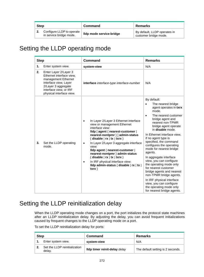
272
Step Command Remarks 2. Configure LLDP to operate
in service bridge mode. lldp mode service-bridge By default, LLDP operates in customer bridge mode.
Setting the LLDP operating mode
Step Command Remarks 1. Enter system view. system-view N/A
2. Enter Layer 2/Layer 3 Ethernet interface view, management Ethernet interface view, Layer 2/Layer 3 aggregate interface view, or IRF physical interface view.
interface interface-type interface-number N/A
3. Set the LLDP operating mode.
• In Layer 2/Layer 3 Ethernet interface view or management Ethernet interface view: lldp [ agent { nearest-customer | nearest-nontpmr } ] admin-status { disable | rx | tx | txrx }
• In Layer 2/Layer 3 aggregate interface view: lldp agent { nearest-customer | nearest-nontpmr } admin-status { disable | rx | tx | txrx }
• In IRF physical interface view: lldp admin-status { disable | rx | tx | txrx }
By default: • The nearest bridge
agent operates in txrx mode.
• The nearest customer bridge agent and nearest non-TPMR bridge agent operate in disable mode.
In Ethernet interface view, if no agent type is specified, the command configures the operating mode for nearest bridge agents. In aggregate interface view, you can configure the operating mode only for nearest customer bridge agents and nearest non-TPMR bridge agents. In IRF physical interface view, you can configure the operating mode only for nearest bridge agents.
Setting the LLDP reinitialization delay When the LLDP operating mode changes on a port, the port initializes the protocol state machines after an LLDP reinitialization delay. By adjusting the delay, you can avoid frequent initializations caused by frequent changes to the LLDP operating mode on a port.
To set the LLDP reinitialization delay for ports:
Step Command Remarks 1. Enter system view. system-view N/A
2. Set the LLDP reinitialization delay. lldp timer reinit-delay delay The default setting is 2 seconds.
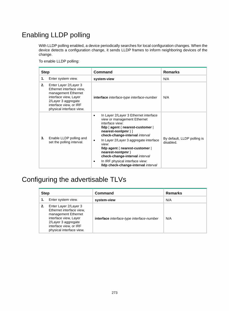
273
Enabling LLDP polling With LLDP polling enabled, a device periodically searches for local configuration changes. When the device detects a configuration change, it sends LLDP frames to inform neighboring devices of the change.
To enable LLDP polling:
Step Command Remarks 1. Enter system view. system-view N/A
2. Enter Layer 2/Layer 3 Ethernet interface view, management Ethernet interface view, Layer 2/Layer 3 aggregate interface view, or IRF physical interface view.
interface interface-type interface-number N/A
3. Enable LLDP polling and set the polling interval.
• In Layer 2/Layer 3 Ethernet interface view or management Ethernet interface view: lldp [ agent { nearest-customer | nearest-nontpmr } ] check-change-interval interval
• In Layer 2/Layer 3 aggregate interface view: lldp agent { nearest-customer | nearest-nontpmr } check-change-interval interval
• In IRF physical interface view: lldp check-change-interval interval
By default, LLDP polling is disabled.
Configuring the advertisable TLVs
Step Command Remarks 1. Enter system view. system-view N/A
2. Enter Layer 2/Layer 3 Ethernet interface view, management Ethernet interface view, Layer 2/Layer 3 aggregate interface view, or IRF physical interface view.
interface interface-type interface-number N/A
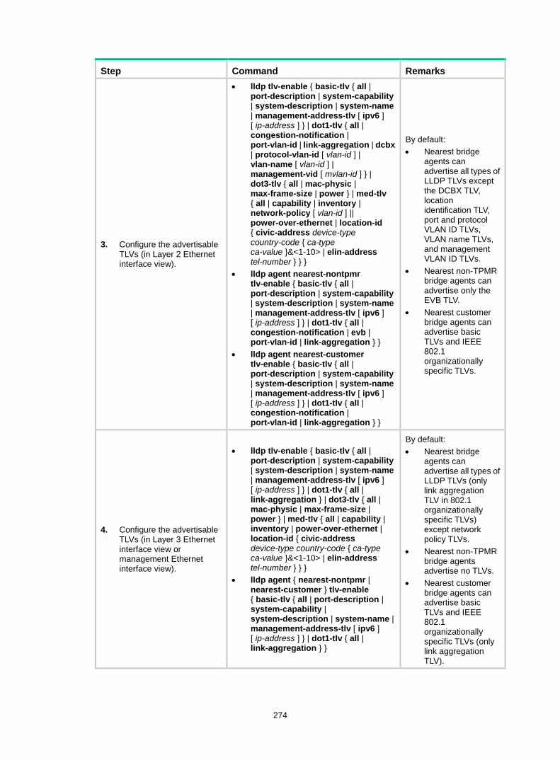
274
Step Command Remarks
3. Configure the advertisable TLVs (in Layer 2 Ethernet interface view).
• lldp tlv-enable { basic-tlv { all | port-description | system-capability | system-description | system-name | management-address-tlv [ ipv6 ] [ ip-address ] } | dot1-tlv { all | congestion-notification | port-vlan-id | link-aggregation | dcbx | protocol-vlan-id [ vlan-id ] | vlan-name [ vlan-id ] | management-vid [ mvlan-id ] } | dot3-tlv { all | mac-physic | max-frame-size | power } | med-tlv { all | capability | inventory | network-policy [ vlan-id ] || power-over-ethernet | location-id { civic-address device-type country-code { ca-type ca-value }&<1-10> | elin-address tel-number } } }
• lldp agent nearest-nontpmr tlv-enable { basic-tlv { all | port-description | system-capability | system-description | system-name | management-address-tlv [ ipv6 ] [ ip-address ] } | dot1-tlv { all | congestion-notification | evb | port-vlan-id | link-aggregation } }
• lldp agent nearest-customer tlv-enable { basic-tlv { all | port-description | system-capability | system-description | system-name | management-address-tlv [ ipv6 ] [ ip-address ] } | dot1-tlv { all | congestion-notification | port-vlan-id | link-aggregation } }
By default: • Nearest bridge
agents can advertise all types of LLDP TLVs except the DCBX TLV, location identification TLV, port and protocol VLAN ID TLVs, VLAN name TLVs, and management VLAN ID TLVs.
• Nearest non-TPMR bridge agents can advertise only the EVB TLV.
• Nearest customer bridge agents can advertise basic TLVs and IEEE 802.1 organizationally specific TLVs.
4. Configure the advertisable TLVs (in Layer 3 Ethernet interface view or management Ethernet interface view).
• lldp tlv-enable { basic-tlv { all | port-description | system-capability | system-description | system-name | management-address-tlv [ ipv6 ] [ ip-address ] } | dot1-tlv { all | link-aggregation } | dot3-tlv { all | mac-physic | max-frame-size | power } | med-tlv { all | capability | inventory | power-over-ethernet | location-id { civic-address device-type country-code { ca-type ca-value }&<1-10> | elin-address tel-number } } }
• lldp agent { nearest-nontpmr | nearest-customer } tlv-enable { basic-tlv { all | port-description | system-capability | system-description | system-name | management-address-tlv [ ipv6 ] [ ip-address ] } | dot1-tlv { all | link-aggregation } }
By default: • Nearest bridge
agents can advertise all types of LLDP TLVs (only link aggregation TLV in 802.1 organizationally specific TLVs) except network policy TLVs.
• Nearest non-TPMR bridge agents advertise no TLVs.
• Nearest customer bridge agents can advertise basic TLVs and IEEE 802.1 organizationally specific TLVs (only link aggregation TLV).
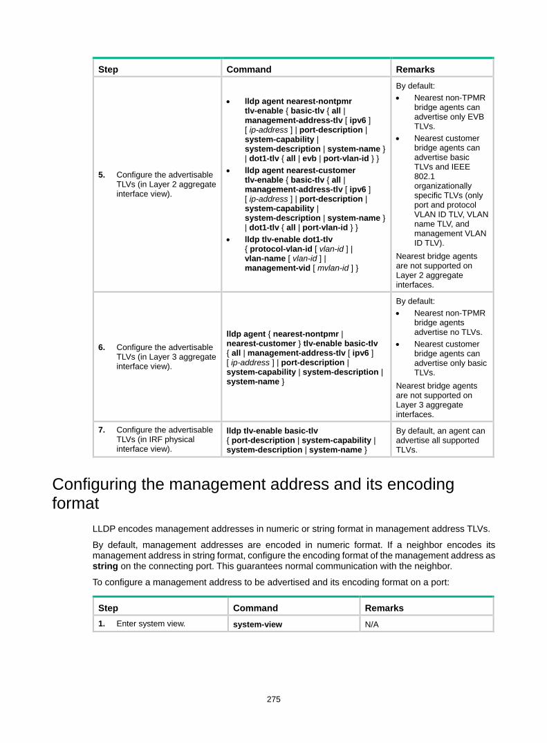
275
Step Command Remarks
5. Configure the advertisable TLVs (in Layer 2 aggregate interface view).
• lldp agent nearest-nontpmr tlv-enable { basic-tlv { all | management-address-tlv [ ipv6 ] [ ip-address ] | port-description | system-capability | system-description | system-name } | dot1-tlv { all | evb | port-vlan-id } }
• lldp agent nearest-customer tlv-enable { basic-tlv { all | management-address-tlv [ ipv6 ] [ ip-address ] | port-description | system-capability | system-description | system-name } | dot1-tlv { all | port-vlan-id } }
• lldp tlv-enable dot1-tlv { protocol-vlan-id [ vlan-id ] | vlan-name [ vlan-id ] | management-vid [ mvlan-id ] }
By default: • Nearest non-TPMR
bridge agents can advertise only EVB TLVs.
• Nearest customer bridge agents can advertise basic TLVs and IEEE 802.1 organizationally specific TLVs (only port and protocol VLAN ID TLV, VLAN name TLV, and management VLAN ID TLV).
Nearest bridge agents are not supported on Layer 2 aggregate interfaces.
6. Configure the advertisable TLVs (in Layer 3 aggregate interface view).
lldp agent { nearest-nontpmr | nearest-customer } tlv-enable basic-tlv { all | management-address-tlv [ ipv6 ] [ ip-address ] | port-description | system-capability | system-description | system-name }
By default: • Nearest non-TPMR
bridge agents advertise no TLVs.
• Nearest customer bridge agents can advertise only basic TLVs.
Nearest bridge agents are not supported on Layer 3 aggregate interfaces.
7. Configure the advertisable TLVs (in IRF physical interface view).
lldp tlv-enable basic-tlv { port-description | system-capability | system-description | system-name }
By default, an agent can advertise all supported TLVs.
Configuring the management address and its encoding format
LLDP encodes management addresses in numeric or string format in management address TLVs.
By default, management addresses are encoded in numeric format. If a neighbor encodes its management address in string format, configure the encoding format of the management address as string on the connecting port. This guarantees normal communication with the neighbor.
To configure a management address to be advertised and its encoding format on a port:
Step Command Remarks 1. Enter system view. system-view N/A
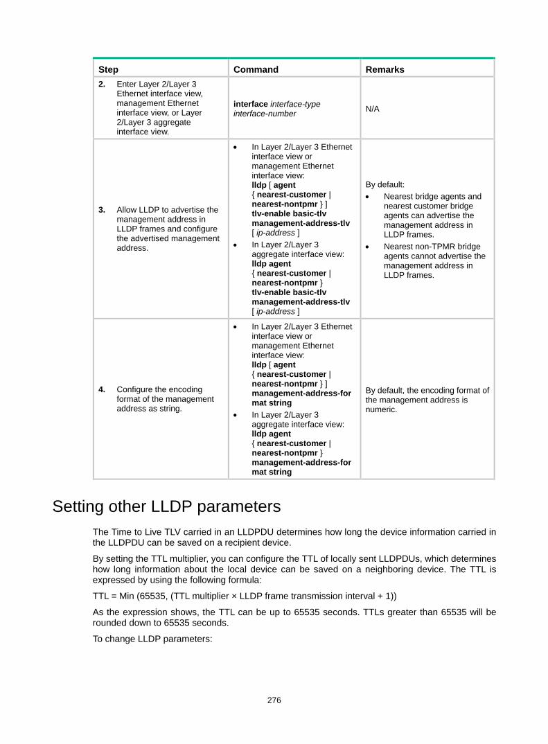
276
Step Command Remarks 2. Enter Layer 2/Layer 3
Ethernet interface view, management Ethernet interface view, or Layer 2/Layer 3 aggregate interface view.
interface interface-type interface-number N/A
3. Allow LLDP to advertise the management address in LLDP frames and configure the advertised management address.
• In Layer 2/Layer 3 Ethernet interface view or management Ethernet interface view: lldp [ agent { nearest-customer | nearest-nontpmr } ] tlv-enable basic-tlv management-address-tlv [ ip-address ]
• In Layer 2/Layer 3 aggregate interface view: lldp agent { nearest-customer | nearest-nontpmr } tlv-enable basic-tlv management-address-tlv [ ip-address ]
By default: • Nearest bridge agents and
nearest customer bridge agents can advertise the management address in LLDP frames.
• Nearest non-TPMR bridge agents cannot advertise the management address in LLDP frames.
4. Configure the encoding format of the management address as string.
• In Layer 2/Layer 3 Ethernet interface view or management Ethernet interface view: lldp [ agent { nearest-customer | nearest-nontpmr } ] management-address-format string
• In Layer 2/Layer 3 aggregate interface view: lldp agent { nearest-customer | nearest-nontpmr } management-address-format string
By default, the encoding format of the management address is numeric.
Setting other LLDP parameters The Time to Live TLV carried in an LLDPDU determines how long the device information carried in the LLDPDU can be saved on a recipient device.
By setting the TTL multiplier, you can configure the TTL of locally sent LLDPDUs, which determines how long information about the local device can be saved on a neighboring device. The TTL is expressed by using the following formula:
TTL = Min (65535, (TTL multiplier × LLDP frame transmission interval + 1))
As the expression shows, the TTL can be up to 65535 seconds. TTLs greater than 65535 will be rounded down to 65535 seconds.
To change LLDP parameters:

277
Step Command Remarks 1. Enter system view. system-view N/A
2. Set the TTL multiplier. lldp hold-multiplier value The default setting is 4.
3. Set the LLDP frame transmission interval. lldp timer tx-interval interval The default setting is 30
seconds.
4. Set the token bucket size for sending LLDP frames. lldp max-credit credit-value The default setting is 5.
5. Set the number of LLDP frames sent each time fast LLDP frame transmission is triggered.
lldp fast-count count The default setting is 4.
6. Set the interval for fast LLDP frame transmission. lldp timer fast-interval interval The default setting is 1 second.
Setting an encapsulation format for LLDP frames LLDP frames can be encapsulated in the following formats: • Ethernet II—With Ethernet II encapsulation configured, an LLDP port sends LLDP frames in
Ethernet II frames. • SNAP—With SNAP encapsulation configured, an LLDP port sends LLDP frames in SNAP
frames.
LLDP of earlier versions requires the same encapsulation format on both ends to process LLDP frames. To successfully communicate with a neighboring device running LLDP of earlier versions, the local device must be configured with the same encapsulation format.
To set the encapsulation format for LLDP frames to SNAP:
Step Command Remarks 1. Enter system view. system-view N/A
2. Enter Layer 2/Layer 3 Ethernet interface view, management Ethernet interface view, Layer 2/Layer 3 aggregate interface view, or IRF physical interface view.
interface interface-type interface-number N/A
3. Set the encapsulation format for LLDP frames to SNAP.
• In Layer 2/Layer 3 Ethernet interface view or management Ethernet interface view: lldp [ agent { nearest-customer | nearest-nontpmr } ] encapsulation snap
• In Layer 2/Layer 3 aggregate interface view: lldp agent { nearest-customer | nearest-nontpmr } encapsulation snap
• In IRF physical interface view: lldp encapsulation snap
By default, Ethernet II encapsulation format applies.
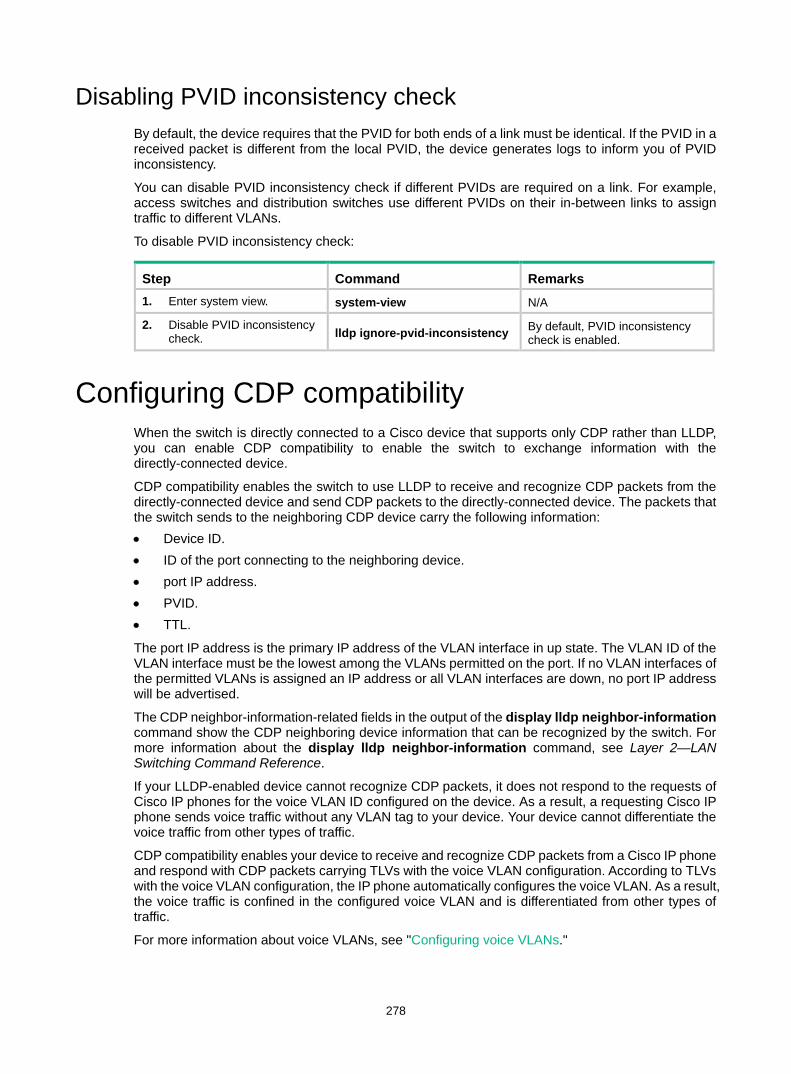
278
Disabling PVID inconsistency check By default, the device requires that the PVID for both ends of a link must be identical. If the PVID in a received packet is different from the local PVID, the device generates logs to inform you of PVID inconsistency.
You can disable PVID inconsistency check if different PVIDs are required on a link. For example, access switches and distribution switches use different PVIDs on their in-between links to assign traffic to different VLANs.
To disable PVID inconsistency check:
Step Command Remarks 1. Enter system view. system-view N/A
2. Disable PVID inconsistency check. lldp ignore-pvid-inconsistency By default, PVID inconsistency
check is enabled.
Configuring CDP compatibility When the switch is directly connected to a Cisco device that supports only CDP rather than LLDP, you can enable CDP compatibility to enable the switch to exchange information with the directly-connected device.
CDP compatibility enables the switch to use LLDP to receive and recognize CDP packets from the directly-connected device and send CDP packets to the directly-connected device. The packets that the switch sends to the neighboring CDP device carry the following information: • Device ID. • ID of the port connecting to the neighboring device. • port IP address. • PVID. • TTL.
The port IP address is the primary IP address of the VLAN interface in up state. The VLAN ID of the VLAN interface must be the lowest among the VLANs permitted on the port. If no VLAN interfaces of the permitted VLANs is assigned an IP address or all VLAN interfaces are down, no port IP address will be advertised.
The CDP neighbor-information-related fields in the output of the display lldp neighbor-information command show the CDP neighboring device information that can be recognized by the switch. For more information about the display lldp neighbor-information command, see Layer 2—LAN Switching Command Reference.
If your LLDP-enabled device cannot recognize CDP packets, it does not respond to the requests of Cisco IP phones for the voice VLAN ID configured on the device. As a result, a requesting Cisco IP phone sends voice traffic without any VLAN tag to your device. Your device cannot differentiate the voice traffic from other types of traffic.
CDP compatibility enables your device to receive and recognize CDP packets from a Cisco IP phone and respond with CDP packets carrying TLVs with the voice VLAN configuration. According to TLVs with the voice VLAN configuration, the IP phone automatically configures the voice VLAN. As a result, the voice traffic is confined in the configured voice VLAN and is differentiated from other types of traffic.
For more information about voice VLANs, see "Configuring voice VLANs."
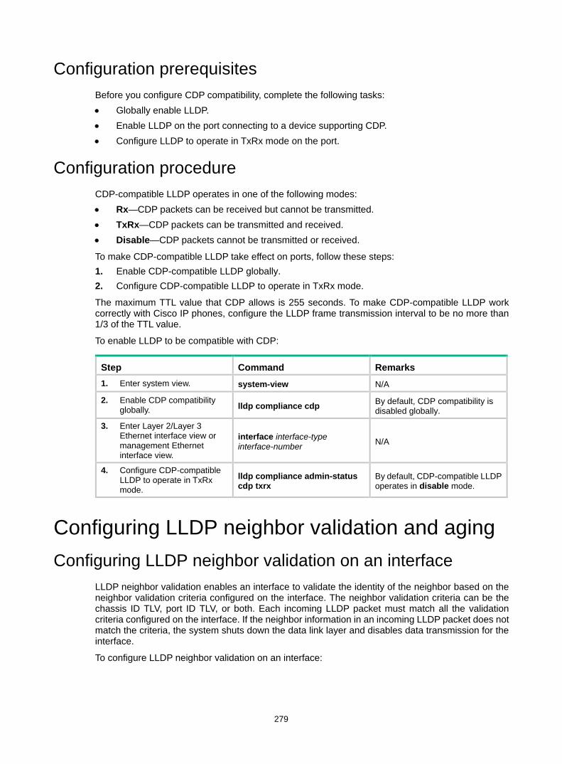
279
Configuration prerequisites Before you configure CDP compatibility, complete the following tasks: • Globally enable LLDP. • Enable LLDP on the port connecting to a device supporting CDP. • Configure LLDP to operate in TxRx mode on the port.
Configuration procedure CDP-compatible LLDP operates in one of the following modes: • Rx—CDP packets can be received but cannot be transmitted. • TxRx—CDP packets can be transmitted and received. • Disable—CDP packets cannot be transmitted or received.
To make CDP-compatible LLDP take effect on ports, follow these steps: 1. Enable CDP-compatible LLDP globally. 2. Configure CDP-compatible LLDP to operate in TxRx mode.
The maximum TTL value that CDP allows is 255 seconds. To make CDP-compatible LLDP work correctly with Cisco IP phones, configure the LLDP frame transmission interval to be no more than 1/3 of the TTL value.
To enable LLDP to be compatible with CDP:
Step Command Remarks 1. Enter system view. system-view N/A
2. Enable CDP compatibility globally. lldp compliance cdp By default, CDP compatibility is
disabled globally.
3. Enter Layer 2/Layer 3 Ethernet interface view or management Ethernet interface view.
interface interface-type interface-number N/A
4. Configure CDP-compatible LLDP to operate in TxRx mode.
lldp compliance admin-status cdp txrx
By default, CDP-compatible LLDP operates in disable mode.
Configuring LLDP neighbor validation and aging Configuring LLDP neighbor validation on an interface
LLDP neighbor validation enables an interface to validate the identity of the neighbor based on the neighbor validation criteria configured on the interface. The neighbor validation criteria can be the chassis ID TLV, port ID TLV, or both. Each incoming LLDP packet must match all the validation criteria configured on the interface. If the neighbor information in an incoming LLDP packet does not match the criteria, the system shuts down the data link layer and disables data transmission for the interface.
To configure LLDP neighbor validation on an interface:
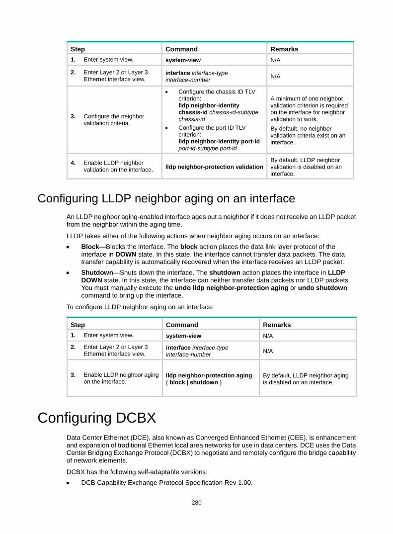
280
Step Command Remarks 1. Enter system view. system-view N/A
2. Enter Layer 2 or Layer 3 Ethernet interface view.
interface interface-type interface-number N/A
3. Configure the neighbor validation criteria.
• Configure the chassis ID TLV criterion: lldp neighbor-identity chassis-id chassis-id-subtype chassis-id
• Configure the port ID TLV criterion: lldp neighbor-identity port-id port-id-subtype port-id
A minimum of one neighbor validation criterion is required on the interface for neighbor validation to work. By default, no neighbor validation criteria exist on an interface.
4. Enable LLDP neighbor validation on the interface. lldp neighbor-protection validation
By default, LLDP neighbor validation is disabled on an interface.
Configuring LLDP neighbor aging on an interface An LLDP neighbor aging-enabled interface ages out a neighbor if it does not receive an LLDP packet from the neighbor within the aging time.
LLDP takes either of the following actions when neighbor aging occurs on an interface: • Block—Blocks the interface. The block action places the data link layer protocol of the
interface in DOWN state. In this state, the interface cannot transfer data packets. The data transfer capability is automatically recovered when the interface receives an LLDP packet.
• Shutdown—Shuts down the interface. The shutdown action places the interface in LLDP DOWN state. In this state, the interface can neither transfer data packets nor LLDP packets. You must manually execute the undo lldp neighbor-protection aging or undo shutdown command to bring up the interface.
To configure LLDP neighbor aging on an interface:
Step Command Remarks 1. Enter system view. system-view N/A
2. Enter Layer 2 or Layer 3 Ethernet interface view.
interface interface-type interface-number N/A
3. Enable LLDP neighbor aging on the interface.
lldp neighbor-protection aging { block | shutdown }
By default, LLDP neighbor aging is disabled on an interface.
Configuring DCBX Data Center Ethernet (DCE), also known as Converged Enhanced Ethernet (CEE), is enhancement and expansion of traditional Ethernet local area networks for use in data centers. DCE uses the Data Center Bridging Exchange Protocol (DCBX) to negotiate and remotely configure the bridge capability of network elements.
DCBX has the following self-adaptable versions: • DCB Capability Exchange Protocol Specification Rev 1.00.
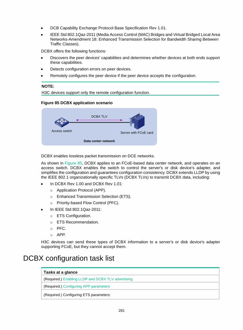
281
• DCB Capability Exchange Protocol Base Specification Rev 1.01. • IEEE Std 802.1Qaz-2011 (Media Access Control (MAC) Bridges and Virtual Bridged Local Area
Networks-Amendment 18: Enhanced Transmission Selection for Bandwidth Sharing Between Traffic Classes).
DCBX offers the following functions: • Discovers the peer devices' capabilities and determines whether devices at both ends support
these capabilities. • Detects configuration errors on peer devices. • Remotely configures the peer device if the peer device accepts the configuration.
NOTE: H3C devices support only the remote configuration function.
Figure 85 DCBX application scenario
DCBX enables lossless packet transmission on DCE networks.
As shown in Figure 85, DCBX applies to an FCoE-based data center network, and operates on an access switch. DCBX enables the switch to control the server's or disk device's adapter, and simplifies the configuration and guarantees configuration consistency. DCBX extends LLDP by using the IEEE 802.1 organizationally specific TLVs (DCBX TLVs) to transmit DCBX data, including: • In DCBX Rev 1.00 and DCBX Rev 1.01:
Application Protocol (APP). Enhanced Transmission Selection (ETS). Priority-based Flow Control (PFC).
• In IEEE Std 802.1Qaz-2011: ETS Configuration. ETS Recommendation. PFC. APP.
H3C devices can send these types of DCBX information to a server's or disk device's adapter supporting FCoE, but they cannot accept them.
DCBX configuration task list
Tasks at a glance (Required.) Enabling LLDP and DCBX TLV advertising
(Required.) Configuring APP parameters
(Required.) Configuring ETS parameters:
Data center network
Server with FCoE cardAccess switch
DCBX TLV
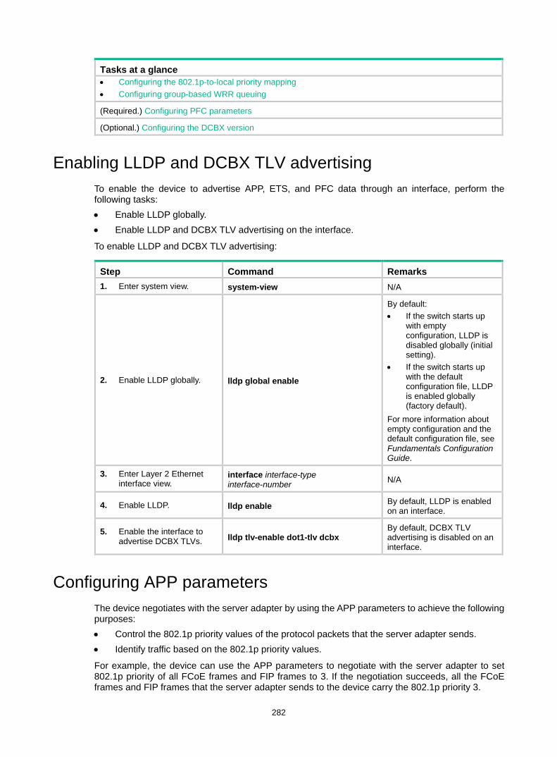
282
Tasks at a glance • Configuring the 802.1p-to-local priority mapping • Configuring group-based WRR queuing
(Required.) Configuring PFC parameters
(Optional.) Configuring the DCBX version
Enabling LLDP and DCBX TLV advertising To enable the device to advertise APP, ETS, and PFC data through an interface, perform the following tasks: • Enable LLDP globally. • Enable LLDP and DCBX TLV advertising on the interface.
To enable LLDP and DCBX TLV advertising:
Step Command Remarks 1. Enter system view. system-view N/A
2. Enable LLDP globally. lldp global enable
By default: • If the switch starts up
with empty configuration, LLDP is disabled globally (initial setting).
• If the switch starts up with the default configuration file, LLDP is enabled globally (factory default).
For more information about empty configuration and the default configuration file, see Fundamentals Configuration Guide.
3. Enter Layer 2 Ethernet interface view.
interface interface-type interface-number N/A
4. Enable LLDP. lldp enable By default, LLDP is enabled on an interface.
5. Enable the interface to advertise DCBX TLVs. lldp tlv-enable dot1-tlv dcbx
By default, DCBX TLV advertising is disabled on an interface.
Configuring APP parameters The device negotiates with the server adapter by using the APP parameters to achieve the following purposes: • Control the 802.1p priority values of the protocol packets that the server adapter sends. • Identify traffic based on the 802.1p priority values.
For example, the device can use the APP parameters to negotiate with the server adapter to set 802.1p priority of all FCoE frames and FIP frames to 3. If the negotiation succeeds, all the FCoE frames and FIP frames that the server adapter sends to the device carry the 802.1p priority 3.
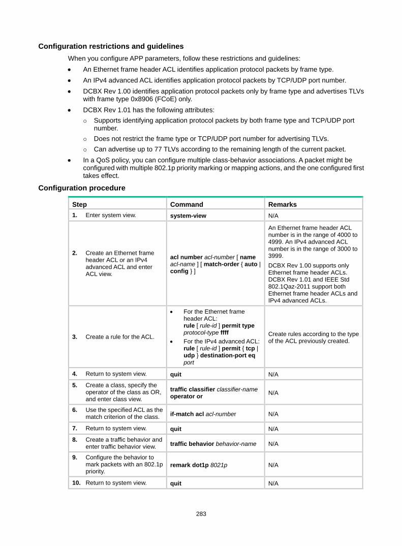
283
Configuration restrictions and guidelines When you configure APP parameters, follow these restrictions and guidelines: • An Ethernet frame header ACL identifies application protocol packets by frame type. • An IPv4 advanced ACL identifies application protocol packets by TCP/UDP port number. • DCBX Rev 1.00 identifies application protocol packets only by frame type and advertises TLVs
with frame type 0x8906 (FCoE) only. • DCBX Rev 1.01 has the following attributes:
Supports identifying application protocol packets by both frame type and TCP/UDP port number.
Does not restrict the frame type or TCP/UDP port number for advertising TLVs. Can advertise up to 77 TLVs according to the remaining length of the current packet.
• In a QoS policy, you can configure multiple class-behavior associations. A packet might be configured with multiple 802.1p priority marking or mapping actions, and the one configured first takes effect.
Configuration procedure
Step Command Remarks 1. Enter system view. system-view N/A
2. Create an Ethernet frame header ACL or an IPv4 advanced ACL and enter ACL view.
acl number acl-number [ name acl-name ] [ match-order { auto | config } ]
An Ethernet frame header ACL number is in the range of 4000 to 4999. An IPv4 advanced ACL number is in the range of 3000 to 3999. DCBX Rev 1.00 supports only Ethernet frame header ACLs. DCBX Rev 1.01 and IEEE Std 802.1Qaz-2011 support both Ethernet frame header ACLs and IPv4 advanced ACLs.
3. Create a rule for the ACL.
• For the Ethernet frame header ACL: rule [ rule-id ] permit type protocol-type ffff
• For the IPv4 advanced ACL: rule [ rule-id ] permit { tcp | udp } destination-port eq port
Create rules according to the type of the ACL previously created.
4. Return to system view. quit N/A
5. Create a class, specify the operator of the class as OR, and enter class view.
traffic classifier classifier-name operator or N/A
6. Use the specified ACL as the match criterion of the class. if-match acl acl-number N/A
7. Return to system view. quit N/A
8. Create a traffic behavior and enter traffic behavior view. traffic behavior behavior-name N/A
9. Configure the behavior to mark packets with an 802.1p priority.
remark dot1p 8021p N/A
10. Return to system view. quit N/A
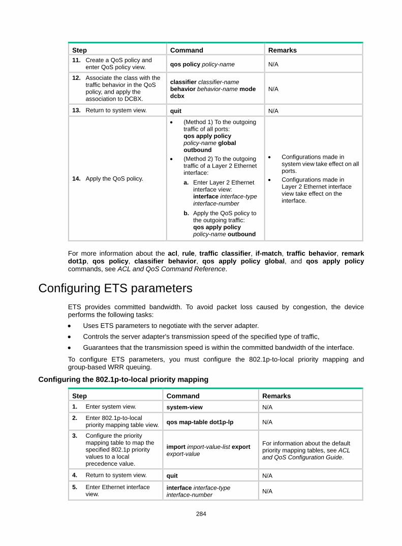
284
Step Command Remarks 11. Create a QoS policy and
enter QoS policy view. qos policy policy-name N/A
12. Associate the class with the traffic behavior in the QoS policy, and apply the association to DCBX.
classifier classifier-name behavior behavior-name mode dcbx
N/A
13. Return to system view. quit N/A
14. Apply the QoS policy.
• (Method 1) To the outgoing traffic of all ports: qos apply policy policy-name global outbound
• (Method 2) To the outgoing traffic of a Layer 2 Ethernet interface: a. Enter Layer 2 Ethernet
interface view: interface interface-type interface-number
b. Apply the QoS policy to the outgoing traffic: qos apply policy policy-name outbound
• Configurations made in system view take effect on all ports.
• Configurations made in Layer 2 Ethernet interface view take effect on the interface.
For more information about the acl, rule, traffic classifier, if-match, traffic behavior, remark dot1p, qos policy, classifier behavior, qos apply policy global, and qos apply policy commands, see ACL and QoS Command Reference.
Configuring ETS parameters ETS provides committed bandwidth. To avoid packet loss caused by congestion, the device performs the following tasks: • Uses ETS parameters to negotiate with the server adapter. • Controls the server adapter's transmission speed of the specified type of traffic, • Guarantees that the transmission speed is within the committed bandwidth of the interface.
To configure ETS parameters, you must configure the 802.1p-to-local priority mapping and group-based WRR queuing.
Configuring the 802.1p-to-local priority mapping
Step Command Remarks 1. Enter system view. system-view N/A
2. Enter 802.1p-to-local priority mapping table view. qos map-table dot1p-lp N/A
3. Configure the priority mapping table to map the specified 802.1p priority values to a local precedence value.
import import-value-list export export-value
For information about the default priority mapping tables, see ACL and QoS Configuration Guide.
4. Return to system view. quit N/A
5. Enter Ethernet interface view.
interface interface-type interface-number N/A
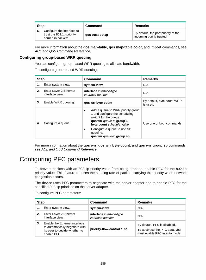
285
Step Command Remarks 6. Configure the interface to
trust the 802.1p priority carried in packets.
qos trust dot1p By default, the port priority of the incoming port is trusted.
For more information about the qos map-table, qos map-table color, and import commands, see ACL and QoS Command Reference.
Configuring group-based WRR queuing You can configure group-based WRR queuing to allocate bandwidth.
To configure group-based WRR queuing:
Step Command Remarks 1. Enter system view. system-view N/A
2. Enter Layer 2 Ethernet interface view.
interface interface-type interface-number N/A
3. Enable WRR queuing. qos wrr byte-count By default, byte-count WRR is used.
4. Configure a queue.
• Add a queue to WRR priority group 1 and configure the scheduling weight for the queue: qos wrr queue-id group 1 byte-count schedule-value
• Configure a queue to use SP queuing: qos wrr queue-id group sp
Use one or both commands.
For more information about the qos wrr, qos wrr byte-count, and qos wrr group sp commands, see ACL and QoS Command Reference.
Configuring PFC parameters To prevent packets with an 802.1p priority value from being dropped, enable PFC for the 802.1p priority value. This feature reduces the sending rate of packets carrying this priority when network congestion occurs.
The device uses PFC parameters to negotiate with the server adapter and to enable PFC for the specified 802.1p priorities on the server adapter.
To configure PFC parameters:
Step Command Remarks 1. Enter system view. system-view N/A
2. Enter Layer 2 Ethernet interface view.
interface interface-type interface-number N/A
3. Enable the Ethernet interface to automatically negotiate with its peer to decide whether to enable PFC.
priority-flow-control auto By default, PFC is disabled. To advertise the PFC data, you must enable PFC in auto mode.

286
Step Command Remarks
4. Enable PFC for the specified 802.1p priorities.
priority-flow-control no-drop dot1p dot1p-list
By default, PFC is disabled for all 802.1p priorities. As a best practice, enable PFC for the 802.1p priority of FCoE traffic. If you enable PFC for multiple 802.1p priorities, packet loss might occur during periods of congestion.
5. Configure the interface to trust the 802.1p priority carried in packets.
qos trust dot1p By default, the port priority of the incoming port is trusted.
For more information about the priority-flow-control and priority-flow-control no-drop dot1p commands, see Interface Command Reference.
Configuring the DCBX version When you configure the DCBX version, follow these restrictions and guidelines: • For DCBX to work correctly, configure the same DCBX version on the local port and peer port.
As a best practice, configure the highest version supported on both ends. IEEE Std 802.1Qaz-2011, DCBX Rev 1.01, and DCBX Rev 1.00 are in descending order.
• After the configuration, LLDP frames sent by the local port carry information about the configured DCBX version. The local port and peer port do not negotiate the DCBX version.
• If the DCBX version is autonegotiated, the version IEEE Std 802.1Qaz-2011 is preferably negotiated.
To configure the DCBX version:
Step Command Remarks 1. Enter system view. system-view N/A
2. Enter Layer 2 Ethernet interface view.
interface interface-type interface-number N/A
3. Configure the DCBX version.
dcbx version { rev100 | rev101 | standard }
By default, the DCBX version is not configured. It is autonegotiated by the local port and peer port.
Configuring LLDP trapping and LLDP-MED trapping
LLDP trapping or LLDP-MED trapping notifies the network management system of events such as newly detected neighboring devices and link failures.
To prevent excessive LLDP traps from being sent when the topology is unstable, set a trap transmission interval for LLDP.
To configure LLDP trapping and LLDP-MED trapping:
Step Command Remarks 1. Enter system view. system-view N/A
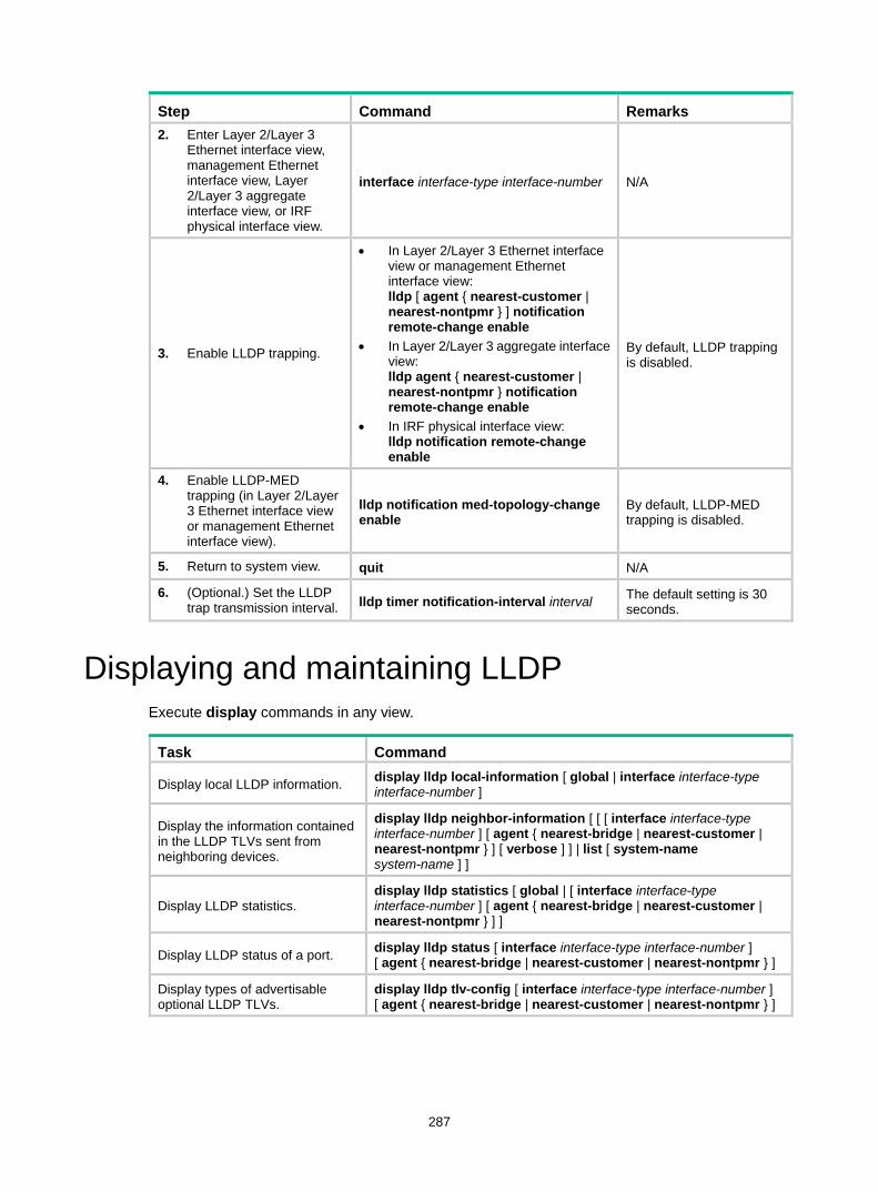
287
Step Command Remarks 2. Enter Layer 2/Layer 3
Ethernet interface view, management Ethernet interface view, Layer 2/Layer 3 aggregate interface view, or IRF physical interface view.
interface interface-type interface-number N/A
3. Enable LLDP trapping.
• In Layer 2/Layer 3 Ethernet interface view or management Ethernet interface view: lldp [ agent { nearest-customer | nearest-nontpmr } ] notification remote-change enable
• In Layer 2/Layer 3 aggregate interface view: lldp agent { nearest-customer | nearest-nontpmr } notification remote-change enable
• In IRF physical interface view: lldp notification remote-change enable
By default, LLDP trapping is disabled.
4. Enable LLDP-MED trapping (in Layer 2/Layer 3 Ethernet interface view or management Ethernet interface view).
lldp notification med-topology-change enable
By default, LLDP-MED trapping is disabled.
5. Return to system view. quit N/A
6. (Optional.) Set the LLDP trap transmission interval. lldp timer notification-interval interval The default setting is 30
seconds.
Displaying and maintaining LLDP Execute display commands in any view.
Task Command
Display local LLDP information. display lldp local-information [ global | interface interface-type interface-number ]
Display the information contained in the LLDP TLVs sent from neighboring devices.
display lldp neighbor-information [ [ [ interface interface-type interface-number ] [ agent { nearest-bridge | nearest-customer | nearest-nontpmr } ] [ verbose ] ] | list [ system-name system-name ] ]
Display LLDP statistics. display lldp statistics [ global | [ interface interface-type interface-number ] [ agent { nearest-bridge | nearest-customer | nearest-nontpmr } ] ]
Display LLDP status of a port. display lldp status [ interface interface-type interface-number ] [ agent { nearest-bridge | nearest-customer | nearest-nontpmr } ]
Display types of advertisable optional LLDP TLVs.
display lldp tlv-config [ interface interface-type interface-number ] [ agent { nearest-bridge | nearest-customer | nearest-nontpmr } ]

288
LLDP configuration examples Basic LLDP configuration example Network requirements
As shown in Figure 86, the NMS and Switch A are located in the same Ethernet network. A MED device and Switch B are connected to FortyGigE 1/0/1 and FortyGigE 1/0/2 of Switch A.
Enable LLDP globally on Switch A and Switch B to perform the following tasks: • Monitor the link between Switch A and Switch B. • Monitor the link between Switch A and the MED device on the NMS.
Figure 86 Network diagram
Configuration procedure 1. Configure Switch A:
# Enable LLDP globally. <SwitchA> system-view
[SwitchA] lldp global enable
# Enable LLDP on FortyGigE 1/0/1. By default, LLDP is enabled on ports. [SwitchA] interface fortygige 1/0/1
[SwitchA-FortyGigE1/0/1] lldp enable
# Set the LLDP operating mode to Rx. [SwitchA-FortyGigE1/0/1] lldp admin-status rx
[SwitchA-FortyGigE1/0/1] quit
# Enable LLDP on FortyGigE 1/0/2. By default, LLDP is enabled on ports. [SwitchA] interface fortygige 1/0/2
[SwitchA-FortyGigE1/0/2] lldp enable
# Set the LLDP operating mode to Rx. [SwitchA-FortyGigE1/0/2] lldp admin-status rx
[SwitchA-FortyGigE1/0/2] quit
2. Configure Switch B: # Enable LLDP globally. <SwitchB> system-view
[SwitchB] lldp global enable
# Enable LLDP on FortyGigE 1/0/1. By default, LLDP is enabled on ports. [SwitchB] interface fortygige 1/0/1
[SwitchB-FortyGigE1/0/1] lldp enable
# Set the LLDP operating mode to Tx.
NMS
Switch A
MED
Switch B
FGE1/0/2 FGE1/0/1
FGE1/0/1
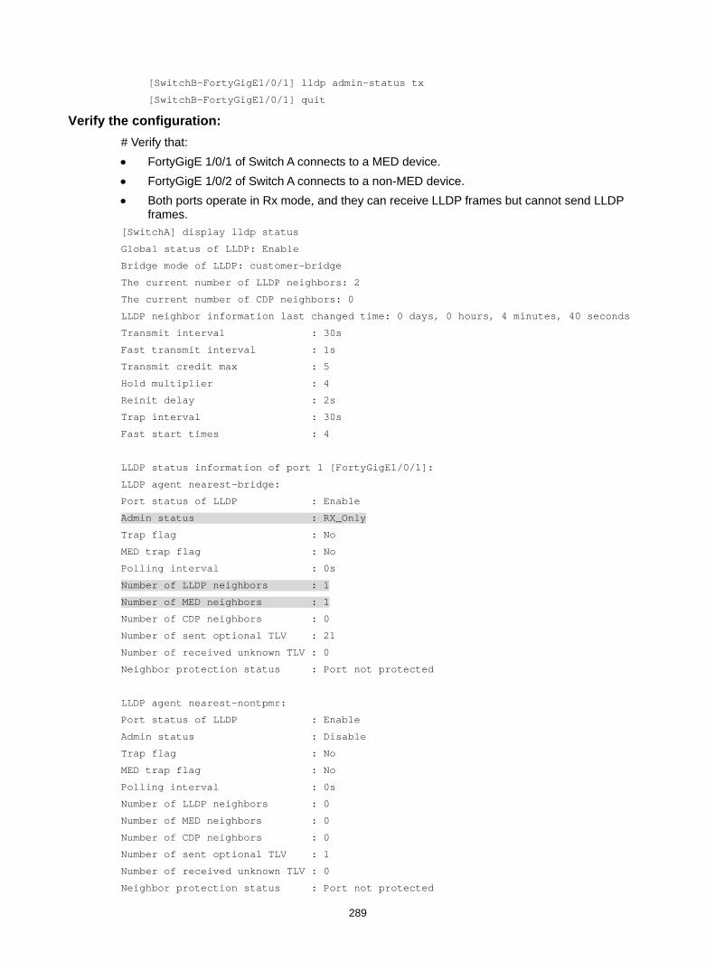
289
[SwitchB-FortyGigE1/0/1] lldp admin-status tx
[SwitchB-FortyGigE1/0/1] quit
Verify the configuration: # Verify that: • FortyGigE 1/0/1 of Switch A connects to a MED device. • FortyGigE 1/0/2 of Switch A connects to a non-MED device. • Both ports operate in Rx mode, and they can receive LLDP frames but cannot send LLDP
frames. [SwitchA] display lldp status
Global status of LLDP: Enable
Bridge mode of LLDP: customer-bridge
The current number of LLDP neighbors: 2
The current number of CDP neighbors: 0
LLDP neighbor information last changed time: 0 days, 0 hours, 4 minutes, 40 seconds
Transmit interval : 30s
Fast transmit interval : 1s
Transmit credit max : 5
Hold multiplier : 4
Reinit delay : 2s
Trap interval : 30s
Fast start times : 4
LLDP status information of port 1 [FortyGigE1/0/1]:
LLDP agent nearest-bridge:
Port status of LLDP : Enable
Admin status : RX_Only
Trap flag : No
MED trap flag : No
Polling interval : 0s
Number of LLDP neighbors : 1
Number of MED neighbors : 1
Number of CDP neighbors : 0
Number of sent optional TLV : 21
Number of received unknown TLV : 0
Neighbor protection status : Port not protected
LLDP agent nearest-nontpmr:
Port status of LLDP : Enable
Admin status : Disable
Trap flag : No
MED trap flag : No
Polling interval : 0s
Number of LLDP neighbors : 0
Number of MED neighbors : 0
Number of CDP neighbors : 0
Number of sent optional TLV : 1
Number of received unknown TLV : 0
Neighbor protection status : Port not protected
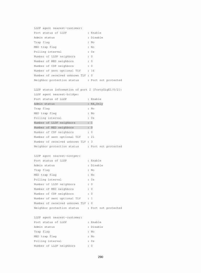
290
LLDP agent nearest-customer:
Port status of LLDP : Enable
Admin status : Disable
Trap flag : No
MED trap flag : No
Polling interval : 0s
Number of LLDP neighbors : 0
Number of MED neighbors : 0
Number of CDP neighbors : 0
Number of sent optional TLV : 16
Number of received unknown TLV : 0
Neighbor protection status : Port not protected
LLDP status information of port 2 [FortyGigE1/0/2]:
LLDP agent nearest-bridge:
Port status of LLDP : Enable
Admin status : RX_Only
Trap flag : No
MED trap flag : No
Polling interval : 0s
Number of LLDP neighbors : 1
Number of MED neighbors : 0
Number of CDP neighbors : 0
Number of sent optional TLV : 21
Number of received unknown TLV : 3
Neighbor protection status : Port not protected
LLDP agent nearest-nontpmr:
Port status of LLDP : Enable
Admin status : Disable
Trap flag : No
MED trap flag : No
Polling interval : 0s
Number of LLDP neighbors : 0
Number of MED neighbors : 0
Number of CDP neighbors : 0
Number of sent optional TLV : 1
Number of received unknown TLV : 0
Neighbor protection status : Port not protected
LLDP agent nearest-customer:
Port status of LLDP : Enable
Admin status : Disable
Trap flag : No
MED trap flag : No
Polling interval : 0s
Number of LLDP neighbors : 0
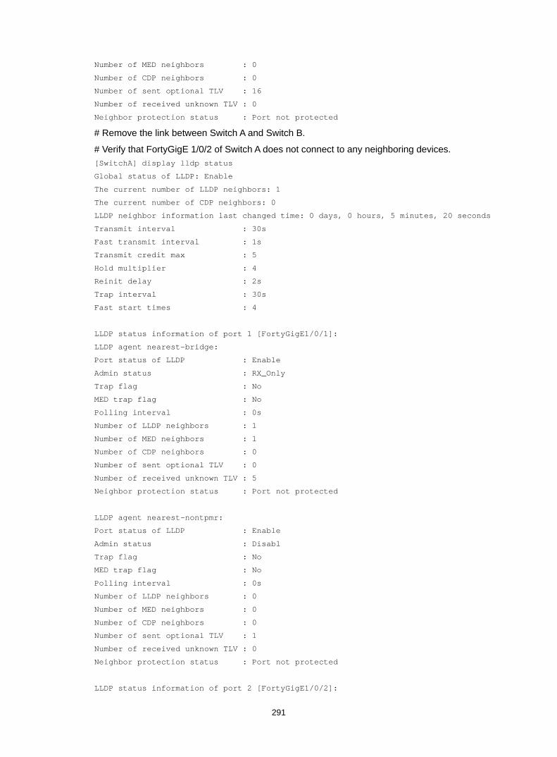
291
Number of MED neighbors : 0
Number of CDP neighbors : 0
Number of sent optional TLV : 16
Number of received unknown TLV : 0
Neighbor protection status : Port not protected
# Remove the link between Switch A and Switch B.
# Verify that FortyGigE 1/0/2 of Switch A does not connect to any neighboring devices. [SwitchA] display lldp status
Global status of LLDP: Enable
The current number of LLDP neighbors: 1
The current number of CDP neighbors: 0
LLDP neighbor information last changed time: 0 days, 0 hours, 5 minutes, 20 seconds
Transmit interval : 30s
Fast transmit interval : 1s
Transmit credit max : 5
Hold multiplier : 4
Reinit delay : 2s
Trap interval : 30s
Fast start times : 4
LLDP status information of port 1 [FortyGigE1/0/1]:
LLDP agent nearest-bridge:
Port status of LLDP : Enable
Admin status : RX_Only
Trap flag : No
MED trap flag : No
Polling interval : 0s
Number of LLDP neighbors : 1
Number of MED neighbors : 1
Number of CDP neighbors : 0
Number of sent optional TLV : 0
Number of received unknown TLV : 5
Neighbor protection status : Port not protected
LLDP agent nearest-nontpmr:
Port status of LLDP : Enable
Admin status : Disabl
Trap flag : No
MED trap flag : No
Polling interval : 0s
Number of LLDP neighbors : 0
Number of MED neighbors : 0
Number of CDP neighbors : 0
Number of sent optional TLV : 1
Number of received unknown TLV : 0
Neighbor protection status : Port not protected
LLDP status information of port 2 [FortyGigE1/0/2]:
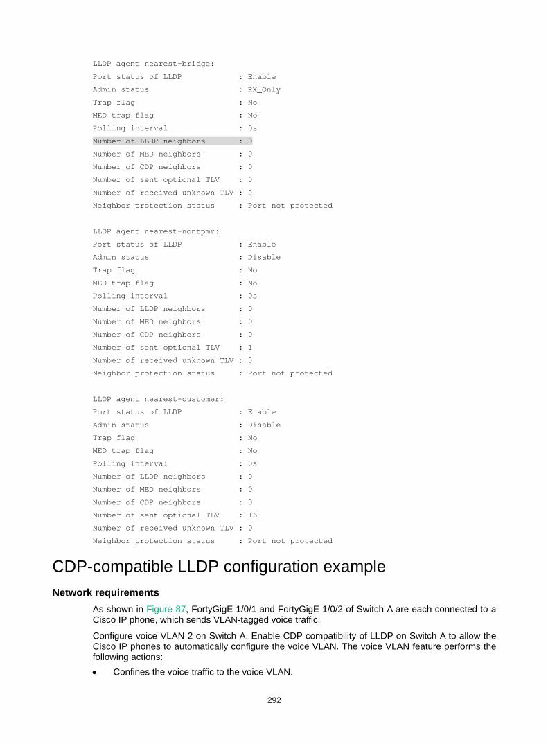
292
LLDP agent nearest-bridge:
Port status of LLDP : Enable
Admin status : RX_Only
Trap flag : No
MED trap flag : No
Polling interval : 0s
Number of LLDP neighbors : 0
Number of MED neighbors : 0
Number of CDP neighbors : 0
Number of sent optional TLV : 0
Number of received unknown TLV : 0
Neighbor protection status : Port not protected
LLDP agent nearest-nontpmr:
Port status of LLDP : Enable
Admin status : Disable
Trap flag : No
MED trap flag : No
Polling interval : 0s
Number of LLDP neighbors : 0
Number of MED neighbors : 0
Number of CDP neighbors : 0
Number of sent optional TLV : 1
Number of received unknown TLV : 0
Neighbor protection status : Port not protected
LLDP agent nearest-customer:
Port status of LLDP : Enable
Admin status : Disable
Trap flag : No
MED trap flag : No
Polling interval : 0s
Number of LLDP neighbors : 0
Number of MED neighbors : 0
Number of CDP neighbors : 0
Number of sent optional TLV : 16
Number of received unknown TLV : 0
Neighbor protection status : Port not protected
CDP-compatible LLDP configuration example Network requirements
As shown in Figure 87, FortyGigE 1/0/1 and FortyGigE 1/0/2 of Switch A are each connected to a Cisco IP phone, which sends VLAN-tagged voice traffic.
Configure voice VLAN 2 on Switch A. Enable CDP compatibility of LLDP on Switch A to allow the Cisco IP phones to automatically configure the voice VLAN. The voice VLAN feature performs the following actions: • Confines the voice traffic to the voice VLAN.

293
• Isolates the voice traffic from other types of traffic.
Figure 87 Network diagram
Configuration procedure 1. Configure a voice VLAN on Switch A:
# Create VLAN 2. <SwitchA> system-view
[SwitchA] vlan 2
[SwitchA-vlan2] quit
# Set the link type of FortyGigE 1/0/1 and FortyGigE 1/0/2 to trunk, and enable voice VLAN on them. [SwitchA] interface fortygige 1/0/1
[SwitchA-FortyGigE1/0/1] port link-type trunk
[SwitchA-FortyGigE1/0/1] voice-vlan 2 enable
[SwitchA-FortyGigE1/0/1] quit
[SwitchA] interface fortygige 1/0/2
[SwitchA-FortyGigE1/0/2] port link-type trunk
[SwitchA-FortyGigE1/0/2] voice-vlan 2 enable
[SwitchA-FortyGigE1/0/2] quit
2. Configure CDP-compatible LLDP on Switch A: # Enable LLDP globally, and enable CDP compatibility globally. [SwitchA] lldp global enable
[SwitchA] lldp compliance cdp
# Enable LLDP on FortyGigE 1/0/1. By default, LLDP is enabled on ports. [SwitchA] interface fortygige 1/0/1
[SwitchA-FortyGigE1/0/1] lldp enable
# Configure LLDP to operate in TxRx mode on FortyGigE 1/0/1. [SwitchA-FortyGigE1/0/1] lldp admin-status txrx
# Configure CDP-compatible LLDP to operate in TxRx mode on FortyGigE 1/0/1. [SwitchA-FortyGigE1/0/1] lldp compliance admin-status cdp txrx
[SwitchA-FortyGigE1/0/1] quit
# Enable LLDP on FortyGigE 1/0/2. By default, LLDP is enabled on ports. [SwitchA] interface fortygige 1/0/2
[SwitchA-FortyGigE1/0/2] lldp enable
# Configure LLDP to operate in TxRx mode on FortyGigE 1/0/2. [SwitchA-FortyGigE1/0/2] lldp admin-status txrx
# Configure CDP-compatible LLDP to operate in TxRx mode on FortyGigE 1/0/2. [SwitchA-FortyGigE1/0/2] lldp compliance admin-status cdp txrx
[SwitchA-FortyGigE1/0/2] quit
Verifying the configuration # Verify that Switch A has completed the following tasks: • Discovering the IP phones connected to FortyGigE 1/0/1 and FortyGigE 1/0/2. • Obtaining IP phone information.
Switch A
FGE1/0/2FGE1/0/1
Cisco IP phone 1 Cisco IP phone 2
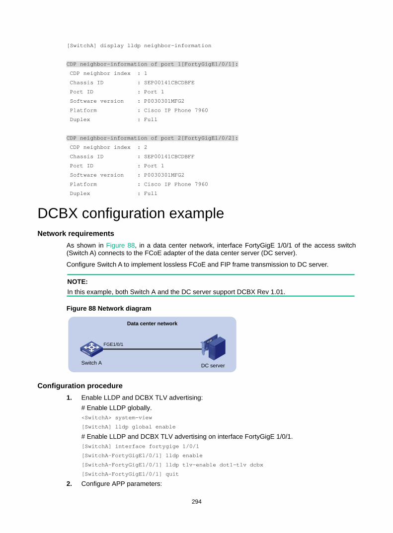
294
[SwitchA] display lldp neighbor-information
CDP neighbor-information of port 1[FortyGigE1/0/1]:
CDP neighbor index : 1
Chassis ID : SEP00141CBCDBFE
Port ID : Port 1
Software version : P0030301MFG2
Platform : Cisco IP Phone 7960
Duplex : Full
CDP neighbor-information of port 2[FortyGigE1/0/2]:
CDP neighbor index : 2
Chassis ID : SEP00141CBCDBFF
Port ID : Port 1
Software version : P0030301MFG2
Platform : Cisco IP Phone 7960
Duplex : Full
DCBX configuration example Network requirements
As shown in Figure 88, in a data center network, interface FortyGigE 1/0/1 of the access switch (Switch A) connects to the FCoE adapter of the data center server (DC server).
Configure Switch A to implement lossless FCoE and FIP frame transmission to DC server.
NOTE: In this example, both Switch A and the DC server support DCBX Rev 1.01.
Figure 88 Network diagram
Configuration procedure 1. Enable LLDP and DCBX TLV advertising:
# Enable LLDP globally. <SwitchA> system-view
[SwitchA] lldp global enable
# Enable LLDP and DCBX TLV advertising on interface FortyGigE 1/0/1. [SwitchA] interface fortygige 1/0/1
[SwitchA-FortyGigE1/0/1] lldp enable
[SwitchA-FortyGigE1/0/1] lldp tlv-enable dot1-tlv dcbx
[SwitchA-FortyGigE1/0/1] quit
2. Configure APP parameters:
Switch A DC server
FGE1/0/1
Data center network
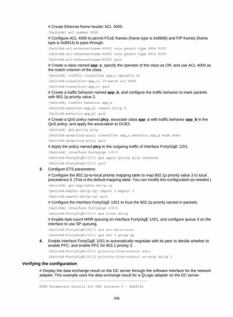
295
# Create Ethernet frame header ACL 4000. [SwitchA] acl number 4000
# Configure ACL 4000 to permit FCoE frames (frame type is 0x8906) and FIP frames (frame type is 0x8914) to pass through. [SwitchA-acl-ethernetframe-4000] rule permit type 8906 ffff
[SwitchA-acl-ethernetframe-4000] rule permit type 8914 ffff
[SwitchA-acl-ethernetframe-4000] quit
# Create a class named app_c, specify the operator of the class as OR, and use ACL 4000 as the match criterion of the class. [SwitchA] traffic classifier app_c operator or
[SwitchA-classifier-app_c] if-match acl 4000
[SwitchA-classifier-app_c] quit
# Create a traffic behavior named app_b, and configure the traffic behavior to mark packets with 802.1p priority value 3. [SwitchA] traffic behavior app_b
[SwitchA-behavior-app_b] remark dot1p 3
[SwitchA-behavior-app_b] quit
# Create a QoS policy named plcy, associate class app_c with traffic behavior app_b in the QoS policy, and apply the association to DCBX. [SwitchA] qos policy plcy
[SwitchA-qospolicy-plcy] classifier app_c behavior app_b mode dcbx
[SwitchA-qospolicy-plcy] quit
# Apply the policy named plcy to the outgoing traffic of interface FortyGigE 1/0/1. [SwitchA] interface fortygige 1/0/1
[SwitchA-FortyGigE1/0/1] qos apply policy plcy outbound
[SwitchA-FortyGigE1/0/1] quit
3. Configure ETS parameters: # Configure the 802.1p-to-local priority mapping table to map 802.1p priority value 3 to local precedence 3. (This is the default mapping table. You can modify this configuration as needed.) [SwitchA] qos map-table dot1p-lp
[SwitchA-maptbl-dot1p-lp] import 3 export 3
[SwitchA-maptbl-dot1p-lp] quit
# Configure the interface FortyGigE 1/0/1 to trust the 802.1p priority carried in packets. [SwitchA] interface fortygige 1/0/1
[SwitchA-FortyGigE1/0/1] qos trust dot1p
# Enable byte-count WRR queuing on interface FortyGigE 1/0/1, and configure queue 3 on the interface to use SP queuing. [SwitchA-FortyGigE1/0/1] qos wrr byte-count
[SwitchA-FortyGigE1/0/1] qos wrr 3 group sp
4. Enable interface FortyGigE 1/0/1 to automatically negotiate with its peer to decide whether to enable PFC, and enable PFC for 802.1 priority 3. [SwitchA-FortyGigE1/0/1] priority-flow-control auto
[SwitchA-FortyGigE1/0/1] priority-flow-control no-drop dot1p 3
Verifying the configuration # Display the data exchange result on the DC server through the software interface for the network adapter. This example uses the data exchange result for a QLogic adapter on the DC server. ------------------------------------------------------
DCBX Parameters Details for CNA Instance 0 - QLE8142
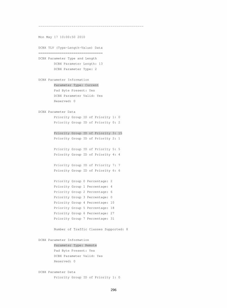
296
------------------------------------------------------
Mon May 17 10:00:50 2010
DCBX TLV (Type-Length-Value) Data
=================================
DCBX Parameter Type and Length
DCBX Parameter Length: 13
DCBX Parameter Type: 2
DCBX Parameter Information
Parameter Type: Current
Pad Byte Present: Yes
DCBX Parameter Valid: Yes
Reserved: 0
DCBX Parameter Data
Priority Group ID of Priority 1: 0
Priority Group ID of Priority 0: 2
Priority Group ID of Priority 3: 15
Priority Group ID of Priority 2: 1
Priority Group ID of Priority 5: 5
Priority Group ID of Priority 4: 4
Priority Group ID of Priority 7: 7
Priority Group ID of Priority 6: 6
Priority Group 0 Percentage: 2
Priority Group 1 Percentage: 4
Priority Group 2 Percentage: 6
Priority Group 3 Percentage: 0
Priority Group 4 Percentage: 10
Priority Group 5 Percentage: 18
Priority Group 6 Percentage: 27
Priority Group 7 Percentage: 31
Number of Traffic Classes Supported: 8
DCBX Parameter Information
Parameter Type: Remote
Pad Byte Present: Yes
DCBX Parameter Valid: Yes
Reserved: 0
DCBX Parameter Data
Priority Group ID of Priority 1: 0

297
Priority Group ID of Priority 0: 2
Priority Group ID of Priority 3: 15
Priority Group ID of Priority 2: 1
Priority Group ID of Priority 5: 5
Priority Group ID of Priority 4: 4
Priority Group ID of Priority 7: 7
Priority Group ID of Priority 6: 6
Priority Group 0 Percentage: 2
Priority Group 1 Percentage: 4
Priority Group 2 Percentage: 6
Priority Group 3 Percentage: 0
Priority Group 4 Percentage: 10
Priority Group 5 Percentage: 18
Priority Group 6 Percentage: 27
Priority Group 7 Percentage: 31
Number of Traffic Classes Supported: 8
DCBX Parameter Information
Parameter Type: Local
Pad Byte Present: Yes
DCBX Parameter Valid: Yes
Reserved: 0
DCBX Parameter Data
Priority Group ID of Priority 1: 0
Priority Group ID of Priority 0: 0
Priority Group ID of Priority 3: 1
Priority Group ID of Priority 2: 0
Priority Group ID of Priority 5: 0
Priority Group ID of Priority 4: 0
Priority Group ID of Priority 7: 0
Priority Group ID of Priority 6: 0
Priority Group 0 Percentage: 50
Priority Group 1 Percentage: 50
Priority Group 2 Percentage: 0
Priority Group 3 Percentage: 0
Priority Group 4 Percentage: 0
Priority Group 5 Percentage: 0
Priority Group 6 Percentage: 0
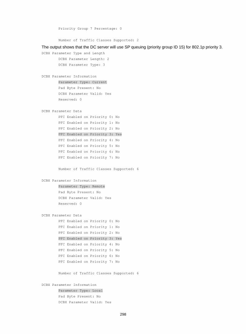
298
Priority Group 7 Percentage: 0
Number of Traffic Classes Supported: 2
The output shows that the DC server will use SP queuing (priority group ID 15) for 802.1p priority 3. DCBX Parameter Type and Length
DCBX Parameter Length: 2
DCBX Parameter Type: 3
DCBX Parameter Information
Parameter Type: Current
Pad Byte Present: No
DCBX Parameter Valid: Yes
Reserved: 0
DCBX Parameter Data
PFC Enabled on Priority 0: No
PFC Enabled on Priority 1: No
PFC Enabled on Priority 2: No
PFC Enabled on Priority 3: Yes
PFC Enabled on Priority 4: No
PFC Enabled on Priority 5: No
PFC Enabled on Priority 6: No
PFC Enabled on Priority 7: No
Number of Traffic Classes Supported: 6
DCBX Parameter Information
Parameter Type: Remote
Pad Byte Present: No
DCBX Parameter Valid: Yes
Reserved: 0
DCBX Parameter Data
PFC Enabled on Priority 0: No
PFC Enabled on Priority 1: No
PFC Enabled on Priority 2: No
PFC Enabled on Priority 3: Yes
PFC Enabled on Priority 4: No
PFC Enabled on Priority 5: No
PFC Enabled on Priority 6: No
PFC Enabled on Priority 7: No
Number of Traffic Classes Supported: 6
DCBX Parameter Information
Parameter Type: Local
Pad Byte Present: No
DCBX Parameter Valid: Yes

299
Reserved: 0
DCBX Parameter Data
PFC Enabled on Priority 0: No
PFC Enabled on Priority 1: No
PFC Enabled on Priority 2: No
PFC Enabled on Priority 3: Yes
PFC Enabled on Priority 4: No
PFC Enabled on Priority 5: No
PFC Enabled on Priority 6: No
PFC Enabled on Priority 7: No
Number of Traffic Classes Supported: 1
The output shows that the DC server will use PFC for 802.1p priority 3.

300
Configuring service loopback groups A service loopback group contains one or multiple Ethernet ports for looping packets sent out by the device back to the device. This feature must work with other features, such as GRE.
A service loopback group provides one of the following services: • Tunnel—Supports unicast tunnel traffic. • Multicast tunnel—Supports multicast tunnel traffic. • Multiport—Supports multiport ARP traffic.
The device supports only one service loopback group for each service type. You can use a service loopback group with multiple features.
Member ports in a service loopback group are load balanced.
Configuration procedure Follow these guidelines when you configure a service loopback group: • Make sure the ports you are assigning to a service loopback group meet the following
requirements: The ports are not used for any other purposes. The configuration on a port is removed when
it is assigned to a service loopback group. The ports support the service type of the service loopback group and are not members of
any other service loopback group. • You cannot change the service type of a service loopback group. • For correct traffic processing, make sure a service loopback group has a minimum of one
member port when it is being used by a feature.
To configure a service loopback group:
Step Command Remarks 1. Enter system view. system-view N/A
2. Create a service loopback group and specify its service type.
service-loopback group number type { { multicast-tunnel | tunnel } * | multiport }
N/A
3. Enter Layer 2 Ethernet interface view.
interface interface-type interface-number N/A
4. Assign the port to the service loopback group.
port service-loopback group number
By default, a service loopback group does not contain ports. You can assign a maximum of 32 ports to a service loopback group.
Displaying and maintaining service loopback groups
Execute display commands in any view.
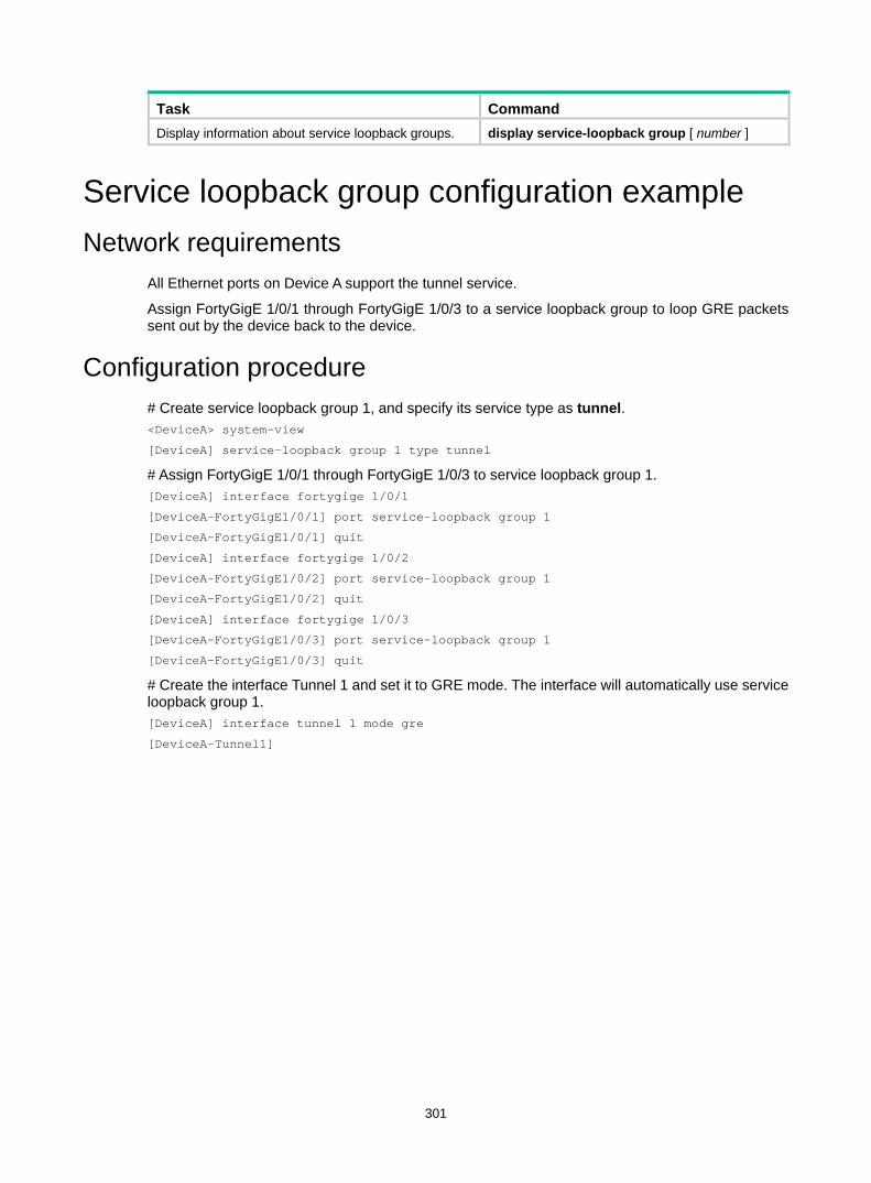
301
Task Command Display information about service loopback groups. display service-loopback group [ number ]
Service loopback group configuration example Network requirements
All Ethernet ports on Device A support the tunnel service.
Assign FortyGigE 1/0/1 through FortyGigE 1/0/3 to a service loopback group to loop GRE packets sent out by the device back to the device.
Configuration procedure # Create service loopback group 1, and specify its service type as tunnel. <DeviceA> system-view
[DeviceA] service-loopback group 1 type tunnel
# Assign FortyGigE 1/0/1 through FortyGigE 1/0/3 to service loopback group 1. [DeviceA] interface fortygige 1/0/1
[DeviceA-FortyGigE1/0/1] port service-loopback group 1
[DeviceA-FortyGigE1/0/1] quit
[DeviceA] interface fortygige 1/0/2
[DeviceA-FortyGigE1/0/2] port service-loopback group 1
[DeviceA-FortyGigE1/0/2] quit
[DeviceA] interface fortygige 1/0/3
[DeviceA-FortyGigE1/0/3] port service-loopback group 1
[DeviceA-FortyGigE1/0/3] quit
# Create the interface Tunnel 1 and set it to GRE mode. The interface will automatically use service loopback group 1. [DeviceA] interface tunnel 1 mode gre
[DeviceA-Tunnel1]
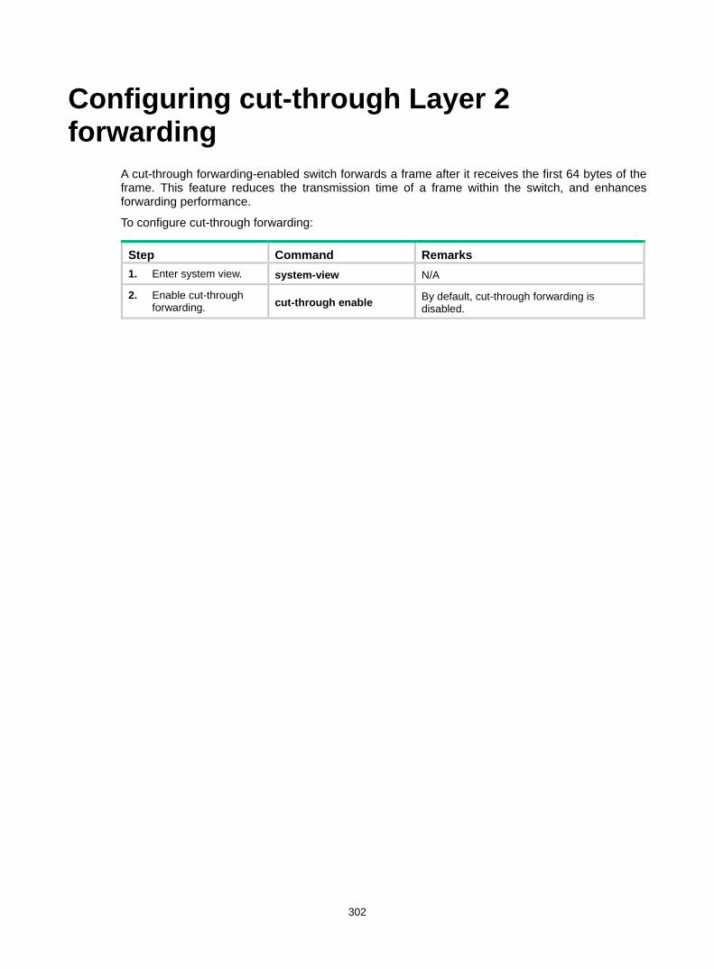
302
Configuring cut-through Layer 2 forwarding
A cut-through forwarding-enabled switch forwards a frame after it receives the first 64 bytes of the frame. This feature reduces the transmission time of a frame within the switch, and enhances forwarding performance.
To configure cut-through forwarding:
Step Command Remarks 1. Enter system view. system-view N/A
2. Enable cut-through forwarding. cut-through enable By default, cut-through forwarding is
disabled.
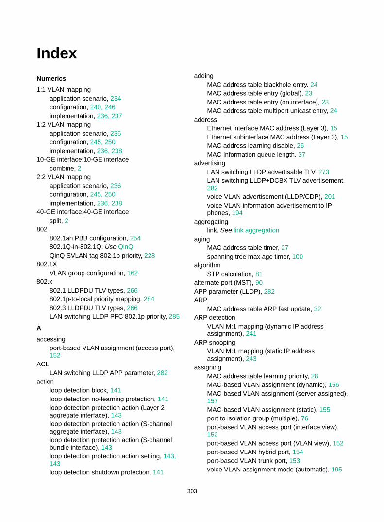
303
Index Numerics 1:1 VLAN mapping
application scenario, 234 configuration, 240, 246 implementation, 236, 237
1:2 VLAN mapping application scenario, 236 configuration, 245, 250 implementation, 236, 238
10-GE interface;10-GE interface combine, 2
2:2 VLAN mapping application scenario, 236 configuration, 245, 250 implementation, 236, 238
40-GE interface;40-GE interface split, 2
802 802.1ah PBB configuration, 254 802.1Q-in-802.1Q. Use QinQ QinQ SVLAN tag 802.1p priority, 228
802.1X VLAN group configuration, 162
802.x 802.1 LLDPDU TLV types, 266 802.1p-to-local priority mapping, 284 802.3 LLDPDU TLV types, 266 LAN switching LLDP PFC 802.1p priority, 285
A accessing
port-based VLAN assignment (access port), 152
ACL LAN switching LLDP APP parameter, 282
action loop detection block, 141 loop detection no-learning protection, 141 loop detection protection action (Layer 2 aggregate interface), 143 loop detection protection action (S-channel aggregate interface), 143 loop detection protection action (S-channel bundle interface), 143 loop detection protection action setting, 143, 143 loop detection shutdown protection, 141
adding MAC address table blackhole entry, 24 MAC address table entry (global), 23 MAC address table entry (on interface), 23 MAC address table multiport unicast entry, 24
address Ethernet interface MAC address (Layer 3), 15 Ethernet subinterface MAC address (Layer 3), 15 MAC address learning disable, 26 MAC Information queue length, 37
advertising LAN switching LLDP advertisable TLV, 273 LAN switching LLDP+DCBX TLV advertisement, 282 voice VLAN advertisement (LLDP/CDP), 201 voice VLAN information advertisement to IP phones, 194
aggregating link. See link aggregation
aging MAC address table timer, 27 spanning tree max age timer, 100
algorithm STP calculation, 81
alternate port (MST), 90 APP parameter (LLDP), 282 ARP
MAC address table ARP fast update, 32 ARP detection
VLAN M:1 mapping (dynamic IP address assignment), 241
ARP snooping VLAN M:1 mapping (static IP address assignment), 243
assigning MAC address table learning priority, 28 MAC-based VLAN assignment (dynamic), 156 MAC-based VLAN assignment (server-assigned), 157 MAC-based VLAN assignment (static), 155 port to isolation group (multiple), 76 port-based VLAN access port (interface view), 152 port-based VLAN access port (VLAN view), 152 port-based VLAN hybrid port, 154 port-based VLAN trunk port, 153 voice VLAN assignment mode (automatic), 195
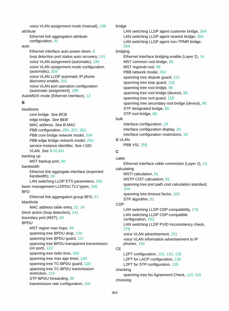
304
voice VLAN assignment mode (manual), 196 attribute
Ethernet link aggregation attribute configuration, 41
auto Ethernet interface auto power-down, 8 loop detection port status auto recovery, 141 voice VLAN assignment (automatic), 195 voice VLAN assignment mode configuration (automatic), 203 voice VLAN LLDP automatic IP phone discovery enable, 201 voice VLAN port operation configuration (automatic assignment), 199
AutoMDIX mode (Ethernet interface), 13
B backbone
core bridge. See BCB edge bridge. See BEB MAC address. See B-MAC PBB configuration, 254, 257, 261 PBB core bridge network model, 254 PBB edge bridge network model, 254 service instance identifier. See I-SID VLAN. See B-VLAN
backing up MST backup port, 90
bandwidth Ethernet link aggregate interface (expected bandwidth), 56 LAN switching LLDP ETS parameters, 284
basic management LLDPDU TLV types, 266 BFD
Ethernet link aggregation group BFD, 57 blackhole
MAC address table entry, 21, 24 block action (loop detection), 141 boundary port (MST), 90 BPDU
MST region max hops, 99 spanning tree BPDU drop, 120 spanning tree BPDU guard, 117 spanning tree BPDU transparent transmission (on port), 122 spanning tree hello time, 100 spanning tree max age timer, 100 spanning tree TC-BPDU guard, 120 spanning tree TC-BPDU transmission restriction, 119 STP BPDU forwarding, 85 transmission rate configuration, 102
bridge LAN switching LLDP agent customer bridge, 264 LAN switching LLDP agent nearest bridge, 264 LAN switching LLDP agent non-TPMR bridge, 264
bridging Ethernet interface bridging enable (Layer 2), 14 MST common root bridge, 90 MST regional root, 89 PBB network model, 254 spanning tree dispute guard, 121 spanning tree loop guard, 118 spanning tree root bridge, 98 spanning tree root bridge (device), 98 spanning tree root guard, 118 spanning tree secondary root bridge (device), 99 STP designated bridge, 80 STP root bridge, 80
bulk interface configuration, 19 interface configuration display, 20 interface configuration restrictions, 19
B-VLAN PBB VSI, 258
C
cable Ethernet interface cable connection (Layer 2), 13
calculating MSTI calculation, 91 MSTP CIST calculation, 91 spanning tree port path cost calculation standard, 104 spanning tree timeout factor, 102 STP algorithm, 81
CDP LAN switching LLDP CDP compatibility, 278 LAN switching LLDP CDP-compatible configuration, 292 LAN switching LLDP PVID inconsistency check, 278 voice VLAN advertisement, 201 voice VLAN information advertisement to IP phones, 194
CE L2PT configuration, 131, 133, 135 L2PT for LACP configuration, 136 L2PT for STP configuration, 135
checking spanning tree No Agreement Check, 113, 115
choosing
305
Ethernet link aggregation reference port, 42, 45
Cisco LAN switching LLDP CDP compatibility, 278 LAN switching LLDP configuration (CDP-compatible), 292 LAN switching LLDP PVID inconsistency check, 278
CIST calculation, 91 network device connection, 89 spanning tree max age timer, 100
combining Ethernet interfaces (10-GE into 40-GE), 2
common root bridge, 90 configuring
common Ethernet interface settings, 1 Ethernet aggregate interface, 53 Ethernet aggregate interface (description), 53 Ethernet aggregate interface (Layer 3 edge), 74 Ethernet interface, 1 Ethernet interface (Layer 2), 11 Ethernet interface (Layer 3), 14 Ethernet interface basic settings, 3 Ethernet interface generic flow control, 6 Ethernet interface jumbo frame support, 4 Ethernet interface link mode, 4 Ethernet interface PFC, 7 Ethernet interface physical state change suppression, 5 Ethernet interface storm control (Layer 2), 11 Ethernet interface storm suppression, 10 Ethernet link aggregate interface (Layer 2 edge), 70 Ethernet link aggregation, 40, 47, 64 Ethernet link aggregation (Layer 2 dynamic), 66 Ethernet link aggregation (Layer 2 static), 64 Ethernet link aggregation (Layer 3 dynamic), 73 Ethernet link aggregation (Layer 3 static), 72 Ethernet link aggregation edge aggregate interface, 56 Ethernet link aggregation group, 48 Ethernet link aggregation group (Layer 2 dynamic), 49 Ethernet link aggregation group (Layer 2 static), 49 Ethernet link aggregation group (Layer 3 dynamic), 51
Ethernet link aggregation group (Layer 3 static), 50 Ethernet link aggregation group BFD, 57 Ethernet link aggregation group load sharing, 58 Ethernet link aggregation load sharing (Layer 2), 68 Ethernet subinterface (Layer 3), 14 ignored field for load sharing, 59 interface (inloopback), 18 interface (loopback), 17 interface (null), 17 IP subnet-based VLAN, 160, 166 L2PT, 131, 133, 135 L2PT for LACP, 136 L2PT for STP, 135 LAN switching LLDP, 264, 270, 288 LAN switching LLDP (CDP-compatible), 292 LAN switching LLDP 802.1p-to-local priority mapping, 284 LAN switching LLDP advertisable TLVs, 273 LAN switching LLDP APP parameter, 282 LAN switching LLDP basics, 270, 288 LAN switching LLDP bridge mode, 271 LAN switching LLDP CDP compatibility, 278 LAN switching LLDP DCBX, 280, 294 LAN switching LLDP ETS parameter, 284 LAN switching LLDP group-based WRR queuing, 285 LAN switching LLDP management address, 275 LAN switching LLDP management address encoding format, 275 LAN switching LLDP PFC parameter, 285 LAN switching LLDP PVID inconsistency check, 278 LAN switching LLDP trapping, 286 LAN switching LLDP-MED trapping, 286 Layer 2 cut-through forwarding, 302 loop detection, 140, 142, 144 MAC address table, 21, 22, 35 MAC address table frame forwarding rule, 28 MAC address table multiport unicast entry (global), 25 MAC address table multiport unicast entry (on interface), 25 MAC Information, 36, 37 MAC Information mode, 37 MAC-based VLAN, 155, 165 MAC-based VLAN (server-assigned), 159 MAC-based VLAN assignment (dynamic), 159 MAC-based VLAN assignment (static), 158 management Ethernet interface, 1
306
MST region, 97 MST region max hops, 99 MSTP, 96, 124 MVRP, 210, 213 PBB, 254, 257, 261 PBB data encapsulation type, 260 PBB downlink port, 259 PBB uplink port, 258 PBB VSI B-VLAN, 258 port isolation, 76 port isolation (multiple isolation groups), 77 port-based VLAN, 151, 163 private VLAN, 177, 178, 180 private VLAN promiscuous port, 180 private VLAN trunk promiscuous port, 183 private VLAN trunk promiscuous+secondary port, 186 protocol-based VLAN, 161, 168 PVST, 95, 127 QinQ, 224, 230 QinQ basics, 230 QinQ CVLAN tag TPID value, 228 QinQ SVLAN tag TPID value, 228 QinQ VLAN tag TPID value, 227 QinQ VLAN transparent transmission, 226, 232 RSTP, 94 S-channel bundle group (dynamic), 52 S-channel bundle group (static), 52 secondary VLAN Layer 3 communication, 190 service loopback group, 300, 301 spanning tree, 79, 92, 124 spanning tree BPDU transmission rate, 102 spanning tree device priority, 99 spanning tree Digest Snooping, 111, 112 spanning tree edge port, 103 spanning tree No Agreement Check, 113, 115 spanning tree port link type, 107 spanning tree port mode, 108 spanning tree port path cost, 103, 106 spanning tree port priority, 107 spanning tree port role restriction, 119 spanning tree protection features, 116 spanning tree root bridge, 98 spanning tree root bridge (device), 98 spanning tree secondary root bridge, 98 spanning tree secondary root bridge (device), 99 spanning tree switched network diameter, 100 spanning tree TC Snooping, 115
spanning tree TC-BPDU transmission restriction, 119 spanning tree timeout factor, 102 spanning tree timer, 100 STP, 93 super VLAN, 172, 172, 174 super VLAN interface, 173 VLAN, 148, 163 VLAN basic settings, 149 VLAN group, 162 VLAN interface, 150 VLAN mapping, 234, 239, 246 VLAN mapping (1:1), 240, 246 VLAN mapping (1:2), 245, 250 VLAN mapping (2:2), 245, 250 VLAN mapping (M:1), 240, 246 VLAN mapping (M:1) (static IP address assignment), 243 VLAN mapping (M:1)(dynamic IP address assignment), 241 VLAN mapping M:1 customer-side port (dynamic IP address assignment), 242 VLAN mapping M:1 customer-side port (static IP address assignment), 244 VLAN mapping M:1 network-side port (dynamic IP address assignment), 242 VLAN mapping M:1 network-side port (static IP address assignment), 244 voice VLAN, 193, 203 voice VLAN advertisement (LLDP/CDP), 201 voice VLAN assignment mode (automatic), 203 voice VLAN assignment mode (manual), 204 voice VLAN port operation (automatic assignment), 199 voice VLAN port operation (manual assignment), 200 voice VLAN traffic QoS priority settings, 198
connecting Ethernet interface cable connection (Layer 2), 13 voice VLAN host+IP phone connection (in series), 195 voice VLAN IP phone+device, 195
Converged Enhanced Ethernet. Use CEE CoS
voice VLAN traffic QoS priority settings, 198 cost
spanning tree port path cost calculation standard, 104 spanning tree port path cost configuration, 103, 106 STP path cost, 81
creating
307
PBB VSI, 258 super VLAN sub-VLAN, 172
CST MST region connection, 89
customer LAN switching LLDP customer bridge mode, 271
cut-through Layer 2 forwarding, 302 CVLAN
QinQ basic configuration, 230 QinQ configuration, 224, 230 QinQ VLAN transparent transmission configuration, 232 VLAN mapping configuration, 234, 239, 246 VLAN mapping implementation, 236
D
data PBB data encapsulation, 260
Data Center Bridging Exchange Protocol. Use DCBX Ethernet. Use DCE
DCBX configuration, 280, 294 LAN switching LLDP APP parameter configuration, 282 LAN switching LLDP ETS parameter configuration, 284 LAN switching LLDP PFC parameter configuration, 285 LAN switching LLDP+DCBX TLV advertisement, 282
default Ethernet link aggregate interface default settings, 58
designated MST port, 90 STP bridge, 80 STP port, 80
detecting Ethernet link aggregation group BFD, 57
device disabling the device to reactivate the shutdown edge ports, 122 Ethernet interface configuration, 1 LAN switching LLDP basic configuration, 270, 288 LAN switching LLDP CDP compatibility, 278 LAN switching LLDP configuration, 264, 270, 288 LAN switching LLDP configuration (CDP-compatible), 292
LAN switching LLDP DCBX configuration, 280, 294, 294 LAN switching LLDP parameters, 276 LAN switching LLDP PVID inconsistency check, 278 Layer 2 cut-through forwarding configuration, 302 loop protection actions, 141 MSTP implementation, 92 MVRP configuration, 207, 210, 213 spanning tree BPDU drop, 120 spanning tree BPDU guard, 117 spanning tree Digest Snooping, 111, 112 spanning tree dispute guard, 121 spanning tree loop guard, 118 spanning tree No Agreement Check, 113, 115 spanning tree port role restriction, 119 spanning tree priority, 99 spanning tree protection features, 116 spanning tree root guard, 118 spanning tree SNMP notification (new-root election, topology change events), 122 spanning tree TC Snooping, 115 spanning tree TC-BPDU guard, 120 spanning tree TC-BPDU transmission restriction, 119 voice VLAN IP phone+device connection, 195
DHCP snooping VLAN M:1 mapping (dynamic IP address assignment), 241
Digest Snooping (spanning tree), 111, 112 directing
Ethernet link aggregation traffic redirection, 61 disabling
MAC address learning (global), 26 MAC address learning (on interface), 26 MAC address learning (on VLAN), 27 static source check, 33
discarding MST discarding port state, 91
displaying bulk interface configuration, 20 Ethernet interface, 15 Ethernet link aggregation, 63 Ethernet subinterface, 15 interface, 18 L2PT, 134 LAN switching LLDP, 287 loop detection, 144 MAC address table, 34 MVRP, 213 PBB, 261
308
port isolation, 76 private VLAN, 180 QinQ, 229 service loopback group, 300 spanning tree, 123 super VLAN, 173 VLAN, 162 VLAN mapping, 246 voice VLAN, 202
dispute spanning tree dispute guard, 121
distance Ethernet interface connection distance (Layer 2), 14
dot1d-1998 (STP port path cost calculation), 104 dot1s (STP port mode), 108 dot1t (STP port path cost calculation), 104 downlink port
PBB configuration, 259 DSCP
voice VLAN traffic QoS priority settings, 198 dynamic
Ethernet link aggregation (dynamic mode), 43 Ethernet link aggregation (Layer 2), 66 Ethernet link aggregation (Layer 3), 73 Ethernet link aggregation edge aggregate interface, 47 Ethernet link aggregation group, 49, 50 Ethernet link aggregation group BFD, 57 Ethernet link aggregation mode, 42 Layer 2 Ethernet link aggregation group, 49 Layer 3 Ethernet link aggregation group, 51 MAC address table dynamic aging timer, 27 MAC address table entry, 21 MAC address table entry configuration (global), 23 MAC address table entry configuration (on interface), 23 MAC-based VLAN assignment, 156, 159 S-channel bundle group, 52
E
edge Ethernet aggregate interface (Layer 3 edge), 74 Ethernet link aggregate interface (Layer 2 edge), 70
edge port MST, 90 spanning tree, 103
EEE energy saving, 9 enabling
BPDU guard on an interface, 117 Ethernet interface auto power-down, 8 Ethernet interface bridging (Layer 2), 14 Ethernet interface EEE energy saving, 9 Ethernet interface energy-saving features, 8 Ethernet link aggregation traffic redirection, 61 global BPDU guard, 117 L2PT, 133 LAN switching LLDP, 270 LAN switching LLDP polling, 273 LAN switching LLDP+DCBX TLV advertisement, 282 loop detection, 142 loop detection (global), 142 loop detection (port-specific), 142 MAC address move notification, 31 MAC address synchronization, 29 MAC address table ARP fast update, 32 MAC address table SNMP notification, 33 MAC Information, 36 MVRP, 211 MVRP GVRP compatibility, 213 PBB L2VPN, 258 QinQ, 226 spanning tree BPDU drop, 120 spanning tree BPDU guard, 117 spanning tree BPDU transparent transmission (on port), 122 spanning tree dispute guard, 121 spanning tree feature, 109 spanning tree loop guard, 118 spanning tree port state transition information output, 109 spanning tree root guard, 118 spanning tree SNMP notification (new-root election, topology change events), 122 spanning tree TC-BPDU guard, 120 VLAN mapping M:1 ARP detection (dynamic IP address assignment), 241 VLAN mapping M:1 ARP snooping (static IP address assignment), 243 VLAN mapping M:1 DHCP snooping (dynamic IP address assignment), 241 voice VLAN LLDP automatic IP phone discovery, 201
encapsulating L2PT configuration, 131, 133, 135 L2PT for LACP configuration, 136 L2PT for STP configuration, 135 LAN switching LLDP frame encapsulated in Ethernet II, 265
309
LAN switching LLDP frame encapsulated in SNAP format, 265 LAN switching LLDP frame encapsulation format, 277 PBB data encapsulation, 260 VLAN frame encapsulation, 148
Energy Efficient Ethernet. See EEE Ethernet
interface. See Ethernet interface LAN switching LLDP APP parameters, 282 LAN switching LLDP DCBX configuration, 280, 294 LAN switching LLDP ETS parameters, 284 LAN switching LLDP frame encapsulated in Ethernet II, 265 LAN switching LLDP group-based WRR queuing, 285 LAN switching LLDP PFC parameters, 285 LAN switching LLDP trapping, 286 LAN switching LLDP+DCBX TLV advertisement, 282 LAN switching LLDP-MED trapping, 286 link aggregation. See Ethernet link aggregation loop detection configuration, 140, 144 loop detection protection action (Layer 2 Ethernet interface), 143 MAC address table configuration, 21, 22, 35 MAC Information configuration, 36, 37 PBB data encapsulation, 260 port isolation configuration, 76 port isolation configuration (multiple isolation groups), 77 port-based VLAN assignment (access port), 152 port-based VLAN assignment (hybrid port), 154 port-based VLAN assignment (trunk port), 153 port-based VLAN configuration, 151 private VLAN configuration, 177, 178, 180 private VLAN promiscuous port configuration, 180 private VLAN trunk promiscuous port configuration, 183 private VLAN trunk promiscuous+secondary port configuration, 186 QinQ CVLAN frame header tag, 224 QinQ SVLAN frame header tag, 224 secondary VLAN Layer 3 communication configuration, 190 service loopback group configuration, 300, 301
subinterface. See Ethernet interface, Ethernet subinterface, subinterface super VLAN configuration, 172, 172, 174 super VLAN sub-VLAN creation, 172 VLAN basic configuration, 149 VLAN configuration, 148, 163 VLAN frame encapsulation, 148 VLAN interface, 150 VLAN port-based configuration, 163 voice VLAN configuration, 193, 203
Ethernet interface 10-GE into 40-GE interface combine;10-GE into 40-GE interface combine, 2 40-GE interface split;40-GE interface split, 2 auto power-down enable, 8 basic settings configuration, 3 bridging enable (Layer 2), 14 cable connection (Layer 2), 13 common settings configuration, 1 configuration, 1 configuration (Layer 2), 11 configuration (Layer 3), 14 connection distance (Layer 2), 14 display, 15 EEE energy saving enable, 9 energy-saving features, 8 fiber port (Layer 2), 9 fiber port restrictions (Layer 2), 10 generic flow control, 6 jumbo frame support configuration, 4 link mode, 4 loopback test, 6 loopback test restrictions, 6 MAC address (Layer 3), 15 maintain, 15 management interface configuration, 1 MDIX mode (Layer 2), 13 MTU setting (Layer 3), 14 naming conventions, 1 physical state change suppression, 5 statistics polling interval, 9 storm control (Layer 2), 11 storm suppression, 10 storm suppression restrictions, 11
Ethernet link aggregation aggregate group Selected ports min/max, 55 aggregate interface, 40 aggregate interface (description), 53 aggregate interface configuration, 53 aggregate interface default settings, 58 aggregate interface shutdown, 57
310
aggregation group, 40 aggregation group restrictions, 48 basic concepts, 40 BFD configuration, 57 configuration, 40, 47, 64 configuration types, 41 display, 63 dynamic mode, 43 edge aggregate interface, 47, 56 group (Layer 3 dynamic), 51 group (Layer 3 static), 50 group configuration, 48 group configuration (Layer 2), 49 group configuration (Layer 3), 50 group load sharing configuration, 58 group load sharing mode, 58 how dynamic link aggregation works, 45 interface configuration (expected bandwidth), 56 LACP, 44 Layer 2 aggregate interface (ignored VLAN), 53, 53 Layer 2 aggregate interface (Layer 2 edge), 70 Layer 2 aggregation configuration (dynamic), 66 Layer 2 aggregation configuration (static), 64 Layer 2 aggregation load sharing (Layer 2), 68 Layer 2 group (dynamic), 49 Layer 2 group (static), 49 Layer 3 aggregate interface (Layer 3 edge), 74 Layer 3 aggregate interface configuration (MAC address), 54 Layer 3 aggregate interface configuration (MTU), 54 Layer 3 aggregation configuration (dynamic), 73 Layer 3 aggregation configuration (static), 72 load sharing mode, 47 local-first load sharing, 59 maintain, 63 management subnet, 63 management VLAN+management port, 62 member port, 40 member port state, 41, 43, 45 modes, 42 operational key, 41 per-flow load sharing algorithm settings, 60 reference port, 45 reference port choice, 42
S-channel bundle group (dynamic), 52 S-channel bundle group (static), 52 S-channel bundle group configuration, 52 static mode, 42 traffic redirection, 61 traffic redirection restrictions, 61
Ethernet subinterface, 1, See also Ethernet interface, Layer 2 Ethernet subinterface, Layer 3 Ethernet subinterface
display, 15 MAC address (Layer 3), 15 maintain, 15 MTU setting (Layer 3), 14
ETS parameter (LLDP), 284 EVB
loop detection protection action (S-channel interface), 143
external Ethernet interface external loopback test, 6
F fast
MAC address table ARP fast update, 32 FCoE
LAN switching LLDP APP parameters, 282 LAN switching LLDP DCBX configuration, 294
fiber port Ethernet interface fiber port (Layer 2), 9
flow control Ethernet interface generic flow control, 6 Ethernet interface PFC, 7
forcing Ethernet interface fiber port (Layer 2), 9
format LAN switching LLDP frame encapsulated in Ethernet II, 265 LAN switching LLDP frame encapsulated in SNAP format, 265 LAN switching LLDP frame encapsulation format, 277 LAN switching LLDP management address encoding format, 275 PBB frame format, 255
forwarding Layer 2 cut-through forwarding configuration, 302 MAC address table frame forwarding rule, 28 MST forwarding port state, 91 spanning tree forward delay timer, 100 STP BPDU forwarding, 85 STP forward delay timer, 86
frame Ethernet interface jumbo frame support, 4

311
Layer 2 cut-through forwarding configuration, 302 loop detection (Ethernet frame header), 140 loop detection (inner frame header), 140 loop detection interval, 141 MAC address learning, 21 MAC address table blackhole entry, 24 MAC address table configuration, 21, 22, 35 MAC address table entry configuration, 23 MAC address table frame forwarding rule, 28 MAC address table multiport unicast entry, 24 MAC Information configuration, 36, 37 port-based VLAN frame handling, 151 QinQ CVLAN Ethernet frame header tag, 224 QinQ implementation, 225 QinQ SVLAN Ethernet frame header tag, 224 VLAN frame encapsulation, 148
G GARP
VLAN Registration Protocol. Use GVRP generic flow control (Ethernet interface), 6 Generic VLAN Registration Protocol. Use GVRP global
Ethernet link aggregation load sharing mode set, 58 loop detection enable, 142 loop detection protection action, 143 MAC address learning disable, 26 MAC address table multiport unicast entry configuration, 25
group Ethernet link aggregate group Selected ports min/max, 55 Ethernet link aggregation, 48 Ethernet link aggregation group, 40 Ethernet link aggregation group (Layer 2 static), 49, 49 Ethernet link aggregation group (Layer 2), 49 Ethernet link aggregation group (Layer 3 dynamic), 51 Ethernet link aggregation group (Layer 3 static), 50 Ethernet link aggregation group (Layer 3), 50 Ethernet link aggregation group load sharing, 58 Ethernet link aggregation LACP, 44 Ethernet link aggregation load sharing mode, 47, 58 Ethernet link aggregation member port state, 41 S-channel bundle group (dynamic), 52
S-channel bundle group (static), 52 VLAN group configuration, 162
GVRP MVRP compatibility, 213
H hello
spanning tree timer, 100 STP timer, 86
host voice VLAN host+IP phone connection (in series), 195 voice VLAN IP phone+device connection, 195
hybrid port port-based VLAN assignment (hybrid port), 154
I identifying
voice VLAN IP phone identification (LLDP), 194 voice VLAN IP phone identification (OUI address), 193
ignored VLAN Layer 2 aggregate interface, 53
implementing 1:1 VLAN mapping, 236, 237 1:2 VLAN mapping, 236, 238 2:2 VLAN mapping, 236, 238 M:1 VLAN mapping, 236, 237 MSTP device implementation, 92 QinQ, 225
inloopback interface configuration, 18 display, 18 maintain, 18
interface bulk configuration, 19 configuration (inloopback), 17, 18 configuration (loopback), 17, 17 configuration (null), 17, 17 Ethernet aggregate interface, 53 Ethernet aggregate interface (description), 53 Ethernet link aggregate interface default settings, 58 Ethernet link aggregate interface shutdown, 57 Ethernet link aggregation edge aggregate interface, 47, 56 Layer 2 Ethernet aggregate interface (ignored VLAN), 53 Layer 3 aggregate interface configuration (MAC address), 54 Layer 3 aggregate interface configuration (MTU), 54
312
LLDP neighbor aging configuration, 280 LLDP neighbor validation configuration, 279
internal Ethernet interface internal loopback test, 6
interval Ethernet link aggregation LACP long timeout, 44 Ethernet link aggregation LACP short timeout, 44 loop detection, 141, 144 MAC change notification interval, 37
IP addressing IP subnet-based VLAN configuration, 160, 166 super VLAN configuration, 172, 172, 174 super VLAN interface configuration, 173 voice VLAN configuration, 193, 203
IP phone voice VLAN assignment mode+IP phone cooperation, 196 voice VLAN host+IP phone connection (in series), 195 voice VLAN identification (LLDP), 194 voice VLAN identification (OUI address), 193 voice VLAN information advertisement, 194 voice VLAN IP phone access method, 195 voice VLAN IP phone+device connection, 195
IP subnet-based VLAN configuration, 160, 166
isolating ports. See port isolation
IST MST region, 89
J jumbo frame support (Ethernet interface), 4
K
key Ethernet link aggregation operational key, 41
L L2PT
configuration, 131, 133, 135 destination multicast MAC address, 134 display, 134 enable, 133 LACP configuration, 136 maintain, 134 operation, 132 STP configuration, 135
L2VPN
PBB enable, 258 LACP
Ethernet link aggregation, 44 L2PT for LACP configuration, 136
LAN Virtual Local Area Network. Use VLAN
LAN switching configuring ignored field for load sharing, 59 displaying LLDP, 287 Ethernet aggregate interface, 53 Ethernet aggregate interface (description), 53 Ethernet aggregate interface (ignored VLAN), 53 Ethernet aggregate interface (Layer 3 edge), 74 Ethernet link aggregate group Selected ports min/max, 55 Ethernet link aggregate interface (expected bandwidth), 56 Ethernet link aggregate interface (Layer 2 edge), 70 Ethernet link aggregate interface default settings, 58 Ethernet link aggregate interface shutdown, 57 Ethernet link aggregation (dynamic mode), 43 Ethernet link aggregation (Layer 2 dynamic), 66 Ethernet link aggregation (Layer 2 static), 64 Ethernet link aggregation (Layer 3 dynamic), 73 Ethernet link aggregation (Layer 3 static), 72 Ethernet link aggregation (static mode), 42 Ethernet link aggregation basic concepts, 40 Ethernet link aggregation configuration, 40, 47, 64 Ethernet link aggregation display, 63 Ethernet link aggregation edge aggregate interface, 47, 56 Ethernet link aggregation group, 48 Ethernet link aggregation group (dynamic dynamic), 49 Ethernet link aggregation group (Layer 2 static), 49 Ethernet link aggregation group (Layer 2), 49 Ethernet link aggregation group (Layer 3 dynamic), 51 Ethernet link aggregation group (Layer 3 static), 50 Ethernet link aggregation group load sharing, 58 Ethernet link aggregation group load sharing mode, 58 Ethernet link aggregation group restrictions, 48 Ethernet link aggregation LACP, 44 Ethernet link aggregation load sharing (Layer 2), 68 Ethernet link aggregation load sharing mode, 47
313
Ethernet link aggregation local-first load sharing, 59 Ethernet link aggregation maintain, 63 Ethernet link aggregation traffic redirection, 61 Ethernet link aggregation traffic redirection restrictions, 61 IP subnet-based VLAN configuration, 160, 166 L2PT configuration, 131, 133, 133, 135 L2PT display, 134 L2PT for LACP configuration, 136 L2PT for STP configuration, 135 L2PT maintain, 134 LLDP basic concepts, 264 LLDP basic configuration, 270, 288 LLDP CDP compatibility, 278 LLDP configuration, 264, 270, 288 LLDP configuration (CDP-compatible), 292 LLDP DCBX configuration, 294 LLDP PVID inconsistency check, 278 MAC address table configuration, 21, 22, 35 MAC Information configuration, 36, 37 MAC-based VLAN assignment (dynamic), 159 MAC-based VLAN assignment (static), 158 MAC-based VLAN configuration, 155, 165 MAC-based VLAN configuration (server-assigned), 159 MAC-based VLAN configuration restrictions, 158 MRP implementation, 207 MVRP configuration, 207, 210, 213 MVRP configuration restrictions, 210 MVRP display, 213 MVRP GVRP compatibility, 213 MVRP maintain, 213 MVRP protocols and standards, 210 MVRP registration mode setting, 212 MVRP timer set, 212 PBB configuration, 254, 257, 261 PBB data encapsulation type configuration, 260 PBB display, 261 PBB downlink port, 259 PBB frame format, 255 PBB frame forwarding, 257 PBB L2VPN enable, 258 PBB maintain, 261 PBB protocols and standards, 257 PBB uplink port, 258 PBB VSI B-VLAN configuration, 258 PBB VSI creation, 258
port isolation configuration, 76 port isolation configuration (multiple isolation groups), 77 port isolation display, 76 port isolation group assignment (multiple), 76 port-based VLAN assignment (access port), 152 port-based VLAN assignment (hybrid port), 154 port-based VLAN assignment (trunk port), 153 port-based VLAN configuration, 151 private VLAN configuration, 178, 180 private VLAN configuration restrictions, 178 private VLAN display, 180 private VLAN promiscuous port configuration, 180 private VLAN trunk promiscuous port configuration, 183 private VLAN trunk promiscuous+secondary port configuration, 186 protocol-based VLAN configuration, 161, 168 QinQ basic configuration, 230 QinQ configuration, 224, 230 QinQ configuration restrictions, 226 QinQ CVLAN tag TPID value, 228 QinQ implementation, 225 QinQ protocols and standards, 225 QinQ SVLAN tag 802.1p priority, 228 QinQ SVLAN tag TPID value, 228 QinQ VLAN tag TPID value, 227 QinQ VLAN transparent transmission configuration, 232 secondary VLAN Layer 3 communication configuration, 190 service loopback group configuration, 300, 301 service loopback group display, 300 super VLAN configuration, 172, 172, 174 super VLAN display, 173 super VLAN interface configuration, 173 super VLAN sub-VLAN creation, 172 troubleshooting PBB, 263 troubleshooting PBB customer frames cannot be transmitted, 263 VLAN basic configuration, 149 VLAN configuration, 148, 163 VLAN display, 162 VLAN group configuration, 162 VLAN interface, 150 VLAN maintain, 162 VLAN port-based configuration, 163 VLAN protocols and standards, 149 voice VLAN advertisement (LLDP/CDP), 201 voice VLAN assignment mode configuration (automatic), 203
314
voice VLAN assignment mode configuration (manual), 204 voice VLAN display, 202 voice VLAN LLDP automatic IP phone discovery enable, 201 voice VLAN port operation configuration (automatic assignment), 199 voice VLAN port operation configuration (manual assignment), 200 voice VLAN port operation configuration restrictions (automatic assignment), 199 voice VLAN port operation configuration restrictions (manual assignment), 200
Layer 2 Ethernet interface bridging enable, 14 Ethernet interface cable connection, 13 Ethernet interface configuration, 1, 11 Ethernet interface connection distance, 14 Ethernet interface fiber port restrictions, 10 Ethernet interface MDIX mode, 13 Ethernet interface storm control configuration, 11 Ethernet link aggregate interface (Layer 2 edge), 70 Ethernet link aggregation (Layer 2 dynamic), 66 Ethernet link aggregation (Layer 2 static), 64 Ethernet link aggregation load sharing, 68 LAN switching LLDP basic configuration, 288 LAN switching LLDP configuration, 288 LAN switching LLDP group-based WRR queuing, 285 LAN switching LLDP trapping, 286 LAN switching LLDP+DCBX TLV advertisement, 282 LAN switching LLDP-MED trapping, 286 loop detection configuration, 140, 142, 144 loop detection protection action (Layer 2 aggregate interface), 143 loop detection protection action (Layer 2 Ethernet interface), 143 loop detection protection action (S-channel aggregate interface), 143 loop detection protection action (S-channel bundle interface), 143 loop detection protection action (S-channel interface), 143 PBB configuration, 254, 257, 261 PBB data encapsulation type configuration, 260 PBB downlink port, 259 PBB frame format, 255 PBB frame forwarding, 257
PBB L2VPN enable, 258 PBB uplink port, 258 PBB VSI B-VLAN configuration, 258 PBB VSI creation, 258 VLAN basic configuration, 149 VLAN configuration, 148, 163 voice VLAN configuration, 193, 203
Layer 2 Ethernet interface fiber port, 9
Layer 2 LAN switching cut-through forwarding configuration, 302 displaying spanning tree, 123 maintaining spanning tree, 123 MST region, 97 MSTP configuration, 124 private VLAN configuration, 177 PVST configuration, 127 spanning tree configuration, 79, 124 spanning tree Digest Snooping, 111, 112 VLAN mapping configuration, 234, 239, 246 VLAN mapping configuration (1:1), 240, 246 VLAN mapping configuration (1:2), 245, 250 VLAN mapping configuration (2:2), 245, 250 VLAN mapping configuration (M:1), 240, 246
Layer 2 Protocol Tunneling. Use L2PT Layer 3
aggregate interface configuration (MAC address), 54 aggregate interface configuration (MTU), 54 Ethernet aggregate interface, 53 Ethernet aggregate interface (description), 53 Ethernet aggregate interface (Layer 3 edge), 74 Ethernet interface configuration, 1, 14 Ethernet interface MAC address, 15 Ethernet interface MTU setting, 14 Ethernet link aggregate group Selected ports min/max, 55 Ethernet link aggregate interface (expected bandwidth), 56 Ethernet link aggregate interface default settings, 58 Ethernet link aggregate interface shutdown, 57 Ethernet link aggregation (Layer 3 dynamic), 73 Ethernet link aggregation (Layer 3 static), 72 Ethernet link aggregation configuration, 40, 47, 64 Ethernet link aggregation edge aggregate interface, 47, 56 Ethernet link aggregation group, 48, 50 Ethernet link aggregation group load sharing, 58 Ethernet link aggregation group load sharing mode, 58

315
Ethernet link aggregation local-first load sharing, 59 Ethernet link aggregation traffic redirection, 61 Ethernet subinterface configuration, 14 Ethernet subinterface MAC address, 15 Ethernet subinterface MTU setting, 14 IP subnet-based VLAN configuration, 160 LAN switching LAN switching VLAN interface, 150 LAN switching LLDP basic configuration, 288 LAN switching LLDP configuration, 288 LAN switching LLDP trapping, 286 LAN switching LLDP-MED trapping, 286 port-based VLAN assignment (access port), 152 port-based VLAN assignment (hybrid port), 154 port-based VLAN assignment (trunk port), 153 port-based VLAN configuration, 151 private VLAN configuration, 180 private VLAN promiscuous port configuration, 180 private VLAN trunk promiscuous port configuration, 183 private VLAN trunk promiscuous+secondary port configuration, 186 protocol-based VLAN configuration, 161 secondary VLAN Layer 3 communication configuration, 190 super VLAN configuration, 174 voice VLAN configuration, 193, 203
learning loop detection no-learning action, 141 MAC address, 21 MAC address learning disable, 26 MAC address table learning limit, 28 MAC address table learning priority, 28 MST learning port state, 91
legacy spanning tree port mode, 108 spanning tree port path cost calculation, 104
link aggregation. See link aggregation Ethernet interface link mode, 4 link layer discovery protocol. Use LLDP MSTP configuration, 124 PVST configuration, 127 spanning tree configuration, 79, 92, 124 spanning tree hello time, 100 spanning tree port link type configuration, 107
link aggregation
Ethernet link aggregation. See Ethernet link aggregation
LLDP 802.1p-to-local priority mapping, 284 advertisable TLV configuration, 273 agent, 264 APP parameter configuration, 282 basic concepts, 264 basic configuration, 270, 288 bridge mode configuration, 271 CDP compatibility configuration, 278 CDP-compatible configuration, 292 configuration, 264, 270, 288 DCBX configuration, 280, 294 disabling PVID inconsistency check, 278 displaying, 287 enable, 270 ETS parameter configuration, 284 group-based WRR queuing, 285 how it works, 269 LAN switching LLDP+DCBX TLV advertisement, 282 LAN switching LLDP-MED trapping configuration, 286 LLDP frame encapsulation format, 277 LLDP frame format, 265 LLDP frame reception, 270 LLDP frame transmission, 269 LLDPDU management address TLV, 269 LLDPDU TLV types, 266 LLDPDU TLVs, 266 management address configuration, 275 management address encoding format, 275 neighbor aging configuration, 279, 280 neighbor validation and aging, 279 neighbor validation configuration, 279, 279 operating mode (disable), 269 operating mode (Rx), 269 operating mode (Tx), 269 operating mode (TxRx), 269 operating mode set, 272 parameter set, 276 PFC parameter configuration, 285 polling enable, 273 protocols and standards, 270 reinitialization delay, 272 trapping configuration, 286 voice VLAN advertisement, 201 voice VLAN information advertisement to IP phones, 194 voice VLAN IP phone identification, 194
316
voice VLAN IP phone identification method, 193 voice VLAN LLDP automatic IP phone discovery enable, 201
LLDP frame encapsulated in Ethernet II format, 265 encapsulated in SNAP format, 265 encapsulation format, 277 receiving, 270 transmitting, 269
LLDPDU LAN switching LLDP basic configuration, 288 LAN switching LLDP configuration, 270, 288 LLDP basic configuration, 270 LLDP configuration, 264 LLDP parameters, 276 management address configuration, 275 management address encoding format, 275 management address TLV, 269 TLV basic management types, 266 TLV LLDP-MED types, 266 TLV organization-specific types, 266
load balancing service loopback group configuration, 300, 301
load sharing configuring ignored field for load sharing, 59 Ethernet link aggregation group configuration, 58 Ethernet link aggregation group load sharing, 47 Ethernet link aggregation load sharing (Layer 2), 68 Ethernet link aggregation load sharing mode, 58 Ethernet link aggregation load sharing mode for MAC-in-MAC traffic (global), 61 Ethernet link aggregation local-first load sharing, 59 Ethernet link aggregation packet type-based load sharing, 47 Ethernet link aggregation per-flow load sharing, 47 Ethernet link aggregation per-flow load sharing algorithm settings, 60 Ethernet link aggregation per-packet load sharing, 47
local Ethernet link aggregation local-first load sharing, 59 Ethernet link aggregation per-flow load sharing algorithm settings, 60
loop MSTP configuration, 124 PVST configuration, 127 spanning tree configuration, 79, 92, 124 spanning tree loop guard, 118
loop detection configuration, 140, 142, 144 display, 144 interval, 141 interval setting, 144 mechanisms, 140 port status auto recovery, 141 protection action setting, 143, 143 protection action setting (Layer 2 aggregate interface), 143 protection action setting (S-channel aggregate interface), 143 protection action setting (S-channel bundle interface), 143 protection actions, 141
loopback Ethernet interface loopback test, 6
loopback interface configuration, 17 display, 18 maintain, 18
M M:1 VLAN mapping
application scenario, 234 ARP detection (dynamic IP address assignment), 241 ARP snooping (static IP address assignment), 243 configuration, 240, 246 configuration (dynamic IP address assignment), 241 configuration (static IP address assignment), 243 customer-side port (dynamic IP address assignment), 242 customer-side port (static IP address assignment), 244 DHCP snooping (dynamic IP address assignment), 241 implementation, 236, 237 network-side port (dynamic IP address assignment), 242 network-side port (static IP address assignment), 244
MAC PBB configuration, 257, 261
MAC address
317
Layer 3 Ethernet aggregate interface, 54 MAC address table
address learning, 21 address synchronization, 29 ARP fast update enable, 32 blackhole entry, 24 configuration, 21, 22, 35 display, 34 dynamic aging timer, 27 entry configuration, 23 entry configuration (global), 23 entry configuration (on interface), 23 entry creation, 21 entry types, 21 frame forwarding rule, 28 learning limit set, 28 learning priority assignment, 28 MAC address learning disable, 26 MAC address move notification, 31 manual entries, 21 multiport unicast entry, 24 SNMP notification enable, 33 static source check disable, 33
MAC addressing Ethernet interface MAC address (Layer 3), 15 Ethernet subinterface MAC address (Layer 3), 15 L2PT destination multicast MAC address, 134 MAC-based VLAN assignment (dynamic), 156, 159 MAC-based VLAN assignment (server-assigned), 157 MAC-based VLAN assignment (static), 155, 158 MAC-based VLAN configuration, 155, 165 MAC-based VLAN configuration (server-assigned), 159 VLAN frame encapsulation, 148
MAC authentication VLAN group configuration, 162
MAC Information change notification interval, 37 configuration, 36, 37 configuration restrictions, 38 enable, 36 mode configuration, 37 queue length setting, 37
MAC relay (LLDP agent), 264 MAC-based VLAN
assignment (dynamic), 159 assignment (static), 158
configuration, 155, 165 configuration (server-assigned), 159 configuration restrictions, 158 dynamic assignment, 156 server-assigned, 157 static assignment, 155
MAC-in-MAC Ethernet link aggregation group load sharing mode for MAC-in-MAC traffic, 61 PBB configuration, 254
maintaining Ethernet interface, 15 Ethernet link aggregation, 63 Ethernet subinterface, 15 interface, 18 L2PT, 134 MVRP, 213 PBB, 261 spanning tree, 123 VLAN, 162
management address LAN switching LLDP encoding format, 275
manual voice VLAN assignment mode, 196 voice VLAN assignment mode configuration, 204 voice VLAN port operation configuration, 200
mapping 1:1 VLAN mapping, 234 1:2 VLAN mapping, 236 2:2 VLAN mapping, 236 M:1 VLAN mapping, 234 MSTP VLAN-to-instance mapping table, 89
master MSTP master port, 90
max age timer (STP), 86 maximum transmission unit. Use MTU mCheck
spanning tree, 110 MDI mode (Ethernet interface), 13 MDIX mode (Ethernet interface), 13 MED (LLDP-MED trapping), 286 message
MRP JoinEmpty, 207 MRP JoinIn, 207 MRP Leave, 207 MRP LeaveAll, 207 MRP New, 207 MRP timers, 209
MIB LAN switching LLDP basic configuration, 270, 288
318
LAN switching LLDP configuration, 264, 270, 288
mode Ethernet interface Auto MDIX (Layer 2), 13 Ethernet interface link mode, 4 Ethernet interface MDI (Layer 2), 13 Ethernet interface MDIX (Layer 2), 13 Ethernet link aggregation dynamic, 42, 43 Ethernet link aggregation LACP operation active, 44 Ethernet link aggregation LACP operation passive, 44 Ethernet link aggregation load sharing, 47 Ethernet link aggregation static, 42, 42 LAN switching LLDP customer bridge mode, 271 LAN switching LLDP disable, 269, 272 LAN switching LLDP Rx, 269, 272 LAN switching LLDP service bridge mode, 271 LAN switching LLDP Tx, 269, 272 LAN switching LLDP TxRx, 269, 272 MAC Information syslog, 37 MAC Information trap, 37 MVRP registration, 212 MVRP registration fixed, 210 MVRP registration forbidden, 210 MVRP registration normal, 210 spanning tree mCheck, 110 spanning tree MSTP, 96 spanning tree PVST, 96 spanning tree RSTP, 96 spanning tree STP, 96 voice VLAN assignment automatic, 195 voice VLAN assignment manual, 196 voice VLAN port operation normal, 197 voice VLAN port operation security, 197
modifying MAC address table blackhole entry, 24 MAC address table entry (global), 23 MAC address table entry (on interface), 23 MAC address table multiport unicast entry, 24
MRP implementation, 207 messages, 207 MVRP configuration, 207, 210, 213 timers, 209
MST region max hops, 99
MSTI calculation, 91
MRP, 207 MST instance, 89
MSTP, 79, See also STP basic concepts, 88 CIST, 89 CIST calculation, 91 common root bridge, 90 configuration, 96, 124 CST, 89 device implementation, 92 feature enable, 109 features, 87 how it works, 91 IST, 89 mode set, 96 MST region, 89 MST region configuration, 97 MSTI, 89 MSTI calculation, 91 port roles, 90 port states, 91 protocols and standards, 92 regional root, 89 relationships, 87 spanning tree max age timer, 100 spanning tree port mode configuration, 108 VLAN-to-instance mapping table, 89
MTU Ethernet subinterface MTU setting (Layer 3), 14 Layer 3 Ethernet aggregate interface, 54
multicast L2PT destination multicast MAC address, 134
multiple Multiple VLAN Registration Protocol. Use MVRP Registration Protocol. Use MRP
Multiple Spanning Tree Protocol. Use MSTP multiport unicast entry (MAC address table), 21, 24 MVRP
configuration, 207, 210, 213 configuration restrictions, 210 display, 213 enable, 211 GVRP compatibility, 213 maintain, 213 MRP implementation, 207 protocols and standards, 210 registration mode setting, 212 registration modes, 210 timer set, 212
N
319
network common Ethernet interface settings configuration, 1 disabling the device to reactivate the shutdown edge ports, 122 Ethernet aggregate interface (Layer 3 edge), 74 Ethernet interface auto power-down, 8 Ethernet interface basic settings, 3 Ethernet interface bridging enable (Layer 2), 14 Ethernet interface cable connection (Layer 2), 13 Ethernet interface configuration (Layer 2), 11 Ethernet interface configuration (Layer 3), 14 Ethernet interface connection distance (Layer 2), 14 Ethernet interface EEE energy saving, 9 Ethernet interface energy-saving features, 8 Ethernet interface fiber port (Layer 2), 9 Ethernet interface generic flow control, 6 Ethernet interface jumbo frame support, 4 Ethernet interface link mode, 4 Ethernet interface loopback test, 6 Ethernet interface MAC address (Layer 3), 15 Ethernet interface MDIX mode (Layer 2), 13 Ethernet interface MTU setting (Layer 3), 14 Ethernet interface PFC, 7 Ethernet interface physical state change suppression, 5 Ethernet interface split (40-GE), 2 Ethernet interface statistics polling interval, 9 Ethernet interface storm control (Layer 2), 11 Ethernet interface storm suppression, 10 Ethernet interfaces combine (10-GE into 40-GE), 2 Ethernet link aggregate interface (Layer 2 edge), 70 Ethernet link aggregation (dynamic mode), 43 Ethernet link aggregation (Layer 2 dynamic), 66 Ethernet link aggregation (Layer 2 static), 64 Ethernet link aggregation (Layer 3 dynamic), 73 Ethernet link aggregation (Layer 3 static), 72 Ethernet link aggregation (static mode), 42 Ethernet link aggregation configuration types, 41 Ethernet link aggregation edge aggregate interface, 47 Ethernet link aggregation LACP, 44
Ethernet link aggregation load sharing (Layer 2), 68 Ethernet link aggregation member port state, 43, 45 Ethernet link aggregation modes, 42 Ethernet link aggregation operational key, 41 Ethernet link aggregation reference port, 45 Ethernet link aggregation reference port choice, 42 Ethernet subinterface configuration (Layer 3), 14 Ethernet subinterface MAC address (Layer 3), 15 Ethernet subinterface MTU setting (Layer 3), 14 interface configuration (inloopback), 18 interface configuration (loopback), 17 interface configuration (null), 17 IP subnet-based VLAN configuration, 160, 166 L2PT for LACP configuration, 136 L2PT for STP configuration, 135 L2PT operation, 132 LAN switching LLDP basic configuration, 270 loop detection enable, 142 loop detection interval, 141, 144 loop detection protection action setting, 143, 143 loop protection actions, 141 MAC address move notification, 31 MAC address table address synchronization, 29 MAC address table ARP fast update, 32 MAC address table blackhole entry, 24 MAC address table dynamic aging timer, 27 MAC address table entry configuration, 23 MAC address table entry types, 21 MAC address table learning limit, 28 MAC address table learning priority, 28 MAC address table multiport unicast entry, 24 MAC address table SNMP notification, 33 MAC Information configuration, 37 MAC-based VLAN assignment (dynamic), 159 MAC-based VLAN assignment (server-assigned), 157 MAC-based VLAN assignment (static), 158 MAC-based VLAN configuration, 155, 165 MAC-based VLAN configuration (server-assigned), 159 management Ethernet interface configuration, 1 MRP timers, 209 MST region configuration, 97 MVRP timer set, 212 PBB frame format, 255 PBB frame forwarding, 257 port isolation group assignment (multiple), 76 port-based VLAN assignment (access port), 152

320
port-based VLAN assignment (hybrid port), 154 port-based VLAN assignment (trunk port), 153 port-based VLAN configuration, 151 private VLAN promiscuous port configuration, 180 private VLAN trunk promiscuous port configuration, 183 private VLAN trunk promiscuous+secondary port configuration, 186 protocol-based VLAN configuration, 161, 168 QinQ basic configuration, 230 QinQ CVLAN tag TPID value, 228 QinQ SVLAN tag TPID value, 228 QinQ VLAN tag TPID value, 227 QinQ VLAN transparent transmission, 226 QinQ VLAN transparent transmission configuration, 232 RSTP network convergence, 86 secondary VLAN Layer 3 communication configuration, 190 service loopback group configuration, 301 spanning tree BPDU drop, 120 spanning tree BPDU guard, 117 spanning tree BPDU transmission rate, 102 spanning tree BPDU transparent transmission (on port), 122 spanning tree Digest Snooping, 111, 112 spanning tree dispute guard, 121 spanning tree edge port, 103 spanning tree loop guard, 118 spanning tree mode set, 96 spanning tree No Agreement Check, 113, 115 spanning tree port link type, 107 spanning tree port mode, 108 spanning tree port path cost, 103, 106 spanning tree port priority, 107 spanning tree port role restriction, 119 spanning tree port state transition, 109 spanning tree priority, 99 spanning tree protection features, 116 spanning tree root bridge, 98 spanning tree root bridge (device), 98 spanning tree root guard, 118 spanning tree secondary root bridge (device), 99 spanning tree SNMP notification (new-root election, topology change events), 122 spanning tree switched network diameter, 100 spanning tree TC Snooping, 115 spanning tree TC-BPDU guard, 120
spanning tree TC-BPDU transmission restriction, 119 STP algorithm calculation, 81 STP designated bridge, 80 STP designated port, 80 STP path cost, 81 STP root bridge, 80 STP root port, 80 super VLAN configuration, 172, 174 super VLAN interface configuration, 173 super VLAN sub-VLAN creation, 172 VLAN basic configuration, 149 VLAN group configuration, 162 VLAN interface, 150 VLAN mapping 1:1 implementation, 237 VLAN mapping 1:2 implementation, 238 VLAN mapping 2:2 implementation, 238 VLAN mapping configuration (1:1), 240 VLAN mapping configuration (1:2), 245 VLAN mapping configuration (2:2), 245 VLAN mapping configuration (M:1), 240 VLAN mapping configuration (M:1) (dynamic IP address assignment), 241 VLAN mapping configuration (M:1) (static IP address assignment), 243 VLAN mapping M:1 customer-side port (dynamic IP address assignment), 242 VLAN mapping M:1 customer-side port (static IP address assignment), 244 VLAN mapping M:1 implementation, 237 VLAN mapping M:1 network-side port (dynamic IP address assignment), 242 VLAN mapping M:1 network-side port (static IP address assignment), 244 VLAN port-based configuration, 163 voice VLAN advertisement (LLDP/CDP), 201 voice VLAN assignment mode, 195 voice VLAN assignment mode configuration (automatic), 203 voice VLAN assignment mode configuration (manual), 204 voice VLAN configuration, 203 voice VLAN host+IP phone connection (in series), 195 voice VLAN information advertisement to IP phones, 194 voice VLAN IP phone access method, 195 voice VLAN IP phone identification (LLDP), 194 voice VLAN IP phone identification (OUI address), 193 voice VLAN IP phone+device connection, 195

321
voice VLAN LLDP automatic IP phone discovery enable, 201 voice VLAN port operation configuration (automatic assignment), 199 voice VLAN port operation configuration (manual assignment), 200 voice VLAN port operation mode, 197 voice VLAN traffic QoS priority settings, 198
network management Ethernet interface configuration, 1 Ethernet link aggregation basic concepts, 40 Ethernet link aggregation configuration, 40, 47, 64 interface bulk configuration, 19 interface configuration (inloopback), 17 interface configuration (loopback), 17 interface configuration (null), 17 L2PT configuration, 131, 133, 135 LAN switching LLDP basic concepts, 264 LAN switching LLDP basic configuration, 288 LAN switching LLDP configuration, 264, 270, 288 LAN switching LLDP configuration (CDP-compatible), 292 LAN switching LLDP DCBX configuration, 280, 294 Layer 2 cut-through forwarding configuration, 302 loop detection, 140 loop detection configuration, 142, 144 MAC address table configuration, 21, 22, 35 MAC Information configuration, 36 MSTP configuration, 124 MVRP, 207, 210, 213 PBB configuration, 254, 257, 261 PBB network model, 254 port isolation configuration, 76 port isolation configuration (multiple isolation groups), 77 private VLAN configuration, 177, 178, 180 PVST configuration, 127 QinQ configuration, 224, 230 service loopback group configuration, 300 spanning tree configuration, 79, 92, 124 super VLAN configuration, 172 VLAN configuration, 148, 163 VLAN mapping configuration, 234, 239, 246 VLAN mapping configuration (1:1), 246 VLAN mapping configuration (1:2), 250 VLAN mapping configuration (2:2), 250 VLAN mapping configuration (M:1), 246 voice VLAN configuration, 193
No Agreement Check (spanning tree), 113, 115 no-learning action (loop detection), 141 normal
voice VLAN operation mode, 197 notification
MAC address move, 31 notifying
MAC address table SNMP notification, 33 MAC Information change notification interval, 37
null interface configuration, 17, 17 display, 18 maintain, 18
O operational key (Ethernet link aggregation), 41 organization-specific LLDPDU TLV types, 266 OUI
voice VLAN IP phone identification (OUI address), 193 voice VLAN IP phone identification method, 193
outputting spanning tree port state transition information, 109
P
packet Ethernet link aggregation group BFD, 57 Ethernet link aggregation packet type-based load sharing, 47 L2PT configuration, 131, 133, 135 L2PT for LACP configuration, 136 L2PT for STP configuration, 135 L2PT operation, 132 LAN switching LLDP CDP compatibility, 278 LAN switching LLDP DCBX configuration, 294 LAN switching LLDP PFC parameters, 285 LAN switching LLDP PVID inconsistency check, 278 service loopback group configuration, 300, 301 spanning tree port mode configuration, 108 STP BPDU protocol packets, 79 STP TCN BPDU protocol packets, 79 VLAN mapping configuration, 234, 239, 246 VLAN mapping configuration (1:1), 240, 246 VLAN mapping configuration (1:2), 245, 250 VLAN mapping configuration (2:2), 245, 250 VLAN mapping configuration (M:1), 240, 246 VLAN mapping configuration (M:1) (dynamic IP address assignment), 241 VLAN mapping configuration (M:1) (static IP address assignment), 243
322
parameter LAN switching LLDP APP configuration, 282 LAN switching LLDP ETS configuration, 284 LAN switching LLDP PFC configuration, 285 spanning tree timeout factor, 102
PBB configuration, 254, 257, 261 data encapsulation type configuration, 260 display, 261 downlink port configuration, 259 frame format, 255 frame forwarding, 257 L2VPN enable, 258 maintain, 261 network model, 254 protocols and standards, 257 terminology, 255 troubleshoot, 263 troubleshooting customer frames cannot be transmitted, 263 uplink port configuration, 258 VSI B-VLAN configuration, 258 VSI creation, 258
PE L2PT configuration, 131, 133, 135 L2PT for LACP configuration, 136 L2PT for STP configuration, 135
per-flow load sharing, 47, 60 performing
Ethernet interface loopback test, 6 spanning tree mCheck, 110
per-packet load sharing, 47 Per-VLAN Spanning Tree Protocol. Use PVST PFC (Ethernet interface), 7 PFC priority (LLDP), 285 physical
Ethernet interface physical state change suppression, 5
polling Ethernet interface statistics polling interval, 9 LAN switching LLDP enable, 273
port Ethernet aggregate interface, 53 Ethernet aggregate interface (description), 53 Ethernet aggregate interface (Layer 3 edge), 74 Ethernet interface fiber port (Layer 2), 9 Ethernet link aggregate group Selected ports min/max, 55 Ethernet link aggregate interface (expected bandwidth), 56
Ethernet link aggregate interface (Layer 2 edge), 70 Ethernet link aggregate interface default settings, 58 Ethernet link aggregate interface shutdown, 57 Ethernet link aggregation (dynamic mode), 43 Ethernet link aggregation (Layer 2 dynamic), 66 Ethernet link aggregation (Layer 2 static), 64 Ethernet link aggregation (Layer 3 dynamic), 73 Ethernet link aggregation (Layer 3 static), 72 Ethernet link aggregation (static mode), 42 Ethernet link aggregation configuration, 40, 47, 64 Ethernet link aggregation configuration types, 41 Ethernet link aggregation edge aggregate interface, 47, 56 Ethernet link aggregation group, 48 Ethernet link aggregation group (Layer 2 static), 49, 49 Ethernet link aggregation group (Layer 2), 49 Ethernet link aggregation group (Layer 3 dynamic), 51 Ethernet link aggregation group (Layer 3 static), 50 Ethernet link aggregation group (Layer 3), 50 Ethernet link aggregation group load sharing, 58 Ethernet link aggregation LACP, 44 Ethernet link aggregation LACP port priority, 44 Ethernet link aggregation load sharing (Layer 2), 68 Ethernet link aggregation load sharing mode, 47 Ethernet link aggregation local-first load sharing, 59 Ethernet link aggregation member port, 40 Ethernet link aggregation member port state, 41, 43, 45 Ethernet link aggregation modes, 42 Ethernet link aggregation operational key, 41 Ethernet link aggregation per-flow load sharing algorithm settings, 60 Ethernet link aggregation reference port, 45 Ethernet link aggregation reference port choice, 42 Ethernet link aggregation traffic redirection, 61 isolation. See port isolation LAN switching LLDP basic configuration, 270, 288 LAN switching LLDP configuration, 264, 270, 288 LAN switching LLDP disable operating mode, 269 LAN switching LLDP enable, 270 LAN switching LLDP frame encapsulation format, 277 LAN switching LLDP frame reception, 270
323
LAN switching LLDP frame transmission, 269 LAN switching LLDP operating mode, 272 LAN switching LLDP polling, 273 LAN switching LLDP reinitialization delay, 272 LAN switching LLDP Rx operating mode, 269 LAN switching LLDP Tx operating mode, 269 LAN switching LLDP TxRx operating mode, 269 Layer 2 aggregate interface (ignored VLAN), 53 Layer 3 aggregate interface configuration (MAC address), 54 Layer 3 aggregate interface configuration (MTU), 54 link aggregation management VLAN+management port, 62 loop detection configuration, 140, 142, 144 loop detection enable (port-specific), 142 loop detection interval, 141, 144 loop detection protection action setting, 143, 143 loop detection protection actions, 141 loop detection status auto recovery, 141 MAC address learning, 21 MAC address table blackhole entry, 24 MAC address table configuration, 21, 22, 35 MAC address table entry configuration, 23 MAC address table multiport unicast entry, 24 MAC Information configuration, 36, 37 MST port roles, 90 MST port states, 91 MVRP application, 207, 210, 213 MVRP timer set, 212 PBB downlink port, 259 PBB uplink port, 258 QinQ implementation, 225 RSTP network convergence, 86 S-channel bundle group, 52 S-channel bundle group (dynamic), 52 S-channel bundle group (static), 52 service loopback group configuration, 300, 301 spanning tree BPDU drop, 120 spanning tree BPDU guard, 117 spanning tree BPDU transmission rate, 102 spanning tree BPDU transparent transmission (on port), 122 spanning tree dispute guard, 121 spanning tree edge port configuration, 103 spanning tree forward delay timer, 100 spanning tree loop guard, 118
spanning tree path cost calculation standard, 104 spanning tree path cost configuration, 103, 106 spanning tree port link type configuration, 107 spanning tree port mode configuration, 108 spanning tree port priority configuration, 107 spanning tree port role restriction, 119 spanning tree port state transition output, 109 spanning tree root guard, 118 spanning tree TC-BPDU guard, 120 spanning tree TC-BPDU transmission restriction, 119 STP designated port, 80 STP root port, 80 VLAN mapping M:1 customer-side port (dynamic IP address assignment), 242 VLAN mapping M:1 customer-side port (static IP address assignment), 244 VLAN mapping M:1 network-side port (dynamic IP address assignment), 242 VLAN mapping M:1 network-side port (static IP address assignment), 244 VLAN port link type, 151 voice VLAN port operation configuration (automatic assignment), 199 voice VLAN port operation configuration (manual assignment), 200 voice VLAN port operation mode, 197
port isolation configuration, 76 configuration (multiple isolation groups), 77 display, 76 port assignment to group (multiple), 76
port-based VLAN assignment (access port), 152 assignment (hybrid port), 154 assignment (trunk port), 153 configuration, 151, 163 port frame handling, 151 port link type, 151 PVID, 151
power Ethernet interface auto power-down, 8 Ethernet interface EEE energy saving, 9 Ethernet interface energy-saving features, 8, 8
priority 802.1p-to-local priority mapping, 284 Ethernet link aggregation LACP, 44 Ethernet link aggregation LACP port priority, 44 Ethernet link aggregation LACP system priority, 44 LAN switching LLDP PFC 802.1p priority, 285
324
MAC address table learning priority, 28 priority-based flow control. Use PFC QinQ SVLAN tag 802.1p priority, 228 spanning tree device priority, 99 spanning tree port priority configuration, 107
private VLAN configuration, 177, 178, 180 configuration restrictions, 178 display, 180 promiscuous port configuration, 180 secondary VLAN Layer 3 communication configuration, 190 trunk promiscuous port configuration, 183 trunk promiscuous+secondary port configuration, 186
procedure adding MAC address table blackhole entry, 24 adding MAC address table entry (global), 23 adding MAC address table entry (on interface), 23 adding MAC address table multiport unicast entry, 24 assigning MAC address table learning priority to interface, 28 assigning port isolation group (multiple), 76 assigning port-based VLAN access port (interface view), 152 assigning port-based VLAN access port (VLAN view), 152 assigning port-based VLAN hybrid port, 154 assigning port-based VLAN trunk port, 153 bulk configuring interfaces, 19 combining Ethernet interfaces (10-GE into 40-GE), 2 configuring common Ethernet interface settings, 1 configuring Ethernet aggregate interface, 53 configuring Ethernet aggregate interface (description), 53 configuring Ethernet aggregate interface (Layer 3 edge), 74 configuring Ethernet interface (Layer 2), 11 configuring Ethernet interface (Layer 3), 14 configuring Ethernet interface auto power-down, 8 configuring Ethernet interface basic settings, 3 configuring Ethernet interface EEE energy saving, 9 configuring Ethernet interface energy-saving features, 8 configuring Ethernet interface generic flow control, 6
configuring Ethernet interface jumbo frame support, 4 configuring Ethernet interface link mode, 4 configuring Ethernet interface PFC, 7 configuring Ethernet interface physical state change suppression, 5 configuring Ethernet interface storm control (Layer 2), 11 configuring Ethernet interface storm suppression, 10 configuring Ethernet link aggregate interface (Layer 2 edge), 70 configuring Ethernet link aggregation, 47 configuring Ethernet link aggregation (Layer 2 dynamic), 66 configuring Ethernet link aggregation (Layer 2 static), 64 configuring Ethernet link aggregation (Layer 3 dynamic), 73 configuring Ethernet link aggregation (Layer 3 static), 72 configuring Ethernet link aggregation edge aggregate interface, 56 configuring Ethernet link aggregation group, 48 configuring Ethernet link aggregation group (Layer 2 dynamic), 49 configuring Ethernet link aggregation group (Layer 2 static), 49 configuring Ethernet link aggregation group (Layer 3 dynamic), 51 configuring Ethernet link aggregation group (Layer 3 static), 50 configuring Ethernet link aggregation group BFD, 57 configuring Ethernet link aggregation group load sharing, 58 configuring Ethernet link aggregation load sharing (Layer 2), 68 configuring Ethernet link aggregation per-flow load sharing algorithm settings, 60 configuring Ethernet subinterface (Layer 3), 14 configuring ignored field for load sharing, 59 configuring interface (inloopback), 18 configuring interface (loopback), 17 configuring interface (null), 17 configuring IP subnet-based VLAN, 160, 166 configuring L2PT, 133 configuring L2PT for LACP, 136 configuring L2PT for STP, 135 configuring LAN switching LLDP, 270, 288 configuring LAN switching LLDP (CDP-compatible), 292
325
configuring LAN switching LLDP 802.1p-to-local priority mapping, 284 configuring LAN switching LLDP advertisable TLVs, 273 configuring LAN switching LLDP APP parameters, 282 configuring LAN switching LLDP basics, 270, 288 configuring LAN switching LLDP bridge mode, 271 configuring LAN switching LLDP CDP compatibility, 278 configuring LAN switching LLDP DCBX, 280, 294 configuring LAN switching LLDP ETS parameters, 284 configuring LAN switching LLDP group-based WRR queuing, 285 configuring LAN switching LLDP management address, 275 configuring LAN switching LLDP management address encoding format, 275 configuring LAN switching LLDP PFC parameters, 285 configuring LAN switching LLDP trapping, 286 configuring LAN switching LLDP-MED trapping, 286 configuring LAN switching QinQ CVLAN tag TPID value, 228 configuring LAN switching QinQ SVLAN tag TPID value, 228 configuring LAN switching QinQ VLAN tag TPID value, 227 configuring Layer 2 cut-through forwarding, 302 configuring LLDP neighbor aging, 280 configuring LLDP neighbor validation, 279 configuring LLDP neighbor validation and aging, 279 configuring loop detection, 142, 144 configuring MAC address table, 22, 35 configuring MAC address table frame forwarding rule, 28 configuring MAC address table multiport unicast entry (global), 25 configuring MAC address table multiport unicast entry (on interface), 25 configuring MAC Information, 37 configuring MAC Information mode, 37 configuring MAC-based VLAN, 155, 165 configuring MAC-based VLAN (server-assigned), 159 configuring MAC-based VLAN assignment (dynamic), 159
configuring MAC-based VLAN assignment (static), 158 configuring management Ethernet interface, 1 configuring MST region, 97 configuring MST region max hops, 99 configuring MSTP, 96, 124 configuring MVRP, 210, 213 configuring PBB, 257, 261 configuring PBB data encapsulation type, 260, 260 configuring PBB downlink port, 259 configuring PBB uplink port, 258 configuring PBB VSI B-VLAN, 258 configuring port isolation (multiple isolation groups), 77 configuring port-based VLAN, 151, 163 configuring private VLAN, 177, 178 configuring private VLAN promiscuous port, 180 configuring private VLAN trunk promiscuous port, 183 configuring private VLAN trunk promiscuous+secondary port, 186 configuring protocol-based VLAN, 161, 168 configuring PVST, 95, 127 configuring QinQ, 230 configuring QinQ basics, 230 configuring QinQ VLAN transparent transmission, 226, 232 configuring RSTP, 94 configuring S-channel bundle group (dynamic), 52 configuring S-channel bundle group (static), 52 configuring secondary VLAN Layer 3 communication, 190 configuring service loopback group, 300, 301 configuring spanning tree, 92, 124 configuring spanning tree BPDU transmission rate, 102 configuring spanning tree device priority, 99 configuring spanning tree Digest Snooping, 111, 112 configuring spanning tree edge port, 103 configuring spanning tree No Agreement Check, 113, 115 configuring spanning tree port link type, 107 configuring spanning tree port mode for MSTP packets, 108 configuring spanning tree port path cost, 103, 106 configuring spanning tree port priority, 107 configuring spanning tree port role restriction, 119 configuring spanning tree protection features, 116 configuring spanning tree root bridge, 98
326
configuring spanning tree root bridge (device), 98 configuring spanning tree secondary root bridge, 98 configuring spanning tree secondary root bridge (device), 99 configuring spanning tree switched network diameter, 100 configuring spanning tree TC Snooping, 115 configuring spanning tree TC-BPDU transmission restriction, 119 configuring spanning tree timeout factor, 102 configuring spanning tree timer, 100 configuring STP, 93 configuring super VLAN, 172, 172, 174 configuring super VLAN interface, 173 configuring VLAN basic settings, 149 configuring VLAN group, 162 configuring VLAN interface, 150 configuring VLAN mapping, 239, 246 configuring VLAN mapping (1:1), 240, 246 configuring VLAN mapping (1:2), 245, 250 configuring VLAN mapping (2:2), 245, 250 configuring VLAN mapping (M:1), 240, 246 configuring VLAN mapping (M:1) (dynamic IP address assignment), 241 configuring VLAN mapping (M:1) (static IP address assignment), 243 configuring VLAN mapping M:1 customer-side port (dynamic IP address assignment), 242 configuring VLAN mapping M:1 customer-side port (static IP address assignment), 244 configuring VLAN mapping M:1 network-side port (dynamic IP address assignment), 242 configuring VLAN mapping M:1 network-side port (static IP address assignment), 244 configuring voice VLAN advertisement (LLDP/CDP), 201 configuring voice VLAN assignment mode (automatic), 203 configuring voice VLAN assignment mode (manual), 204 configuring voice VLAN port operation (automatic assignment), 199 configuring voice VLAN port operation (manual assignment), 200 configuring voice VLAN traffic QoS priority settings, 198 creating PBB VSI, 258 creating super VLAN sub-VLAN, 172 disabling LAN switching LLDP PVID inconsistency check, 278 disabling MAC address learning (global), 26
disabling MAC address learning (on interface), 26 disabling MAC address learning (on VLAN), 27 disabling static source check, 33 disabling the device to reactivate the shutdown edge ports, 122 displaying bulk interface configuration, 20 displaying Ethernet interface, 15 displaying Ethernet link aggregation, 63 displaying Ethernet subinterface, 15 displaying interface, 18 displaying L2PT, 134 displaying LAN switching LLDP, 287 displaying loop detection, 144 displaying MAC address table, 34 displaying MVRP, 213 displaying PBB, 261 displaying port isolation, 76 displaying private VLAN, 180 displaying QinQ, 229 displaying service loopback group, 300 displaying spanning tree, 123 displaying super VLAN, 173 displaying VLAN, 162 displaying VLAN mapping, 246 displaying voice VLAN, 202 enable Ethernet interface bridging (Layer 2), 14 enabling BPDU guard on an interface, 117 enabling Ethernet link aggregation local-first load sharing, 59 enabling Ethernet link aggregation traffic redirection, 61 enabling global BPDU guard, 117 enabling L2PT, 133 enabling LAN switching LLDP, 270 enabling LAN switching LLDP polling, 273 enabling LAN switching LLDP+DCBX TLV advertisement, 282 enabling loop detection (global), 142 enabling loop detection (port-specific), 142 enabling MAC address move notification, 31 enabling MAC address synchronization, 29 enabling MAC address table ARP fast update, 32 enabling MAC address table SNMP notification, 33 enabling MAC Information, 36 enabling MVRP, 211 enabling MVRP GVRP compatibility, 213 enabling PBB L2VPN, 258 enabling QinQ, 226 enabling spanning tree BPDU drop, 120 enabling spanning tree BPDU guard, 117
327
enabling spanning tree BPDU transparent transmission (on port), 122 enabling spanning tree dispute guard, 121 enabling spanning tree feature, 109 enabling spanning tree loop guard, 118 enabling spanning tree port state transition information output, 109 enabling spanning tree root guard, 118 enabling spanning tree SNMP notification (new-root election, topology change events), 122 enabling spanning tree TC-BPDU guard, 120 enabling VLAN mapping M:1 ARP detection (dynamic IP address assignment), 241 enabling VLAN mapping M:1 ARP snooping (static IP address assignment), 243 enabling VLAN mapping M:1 DHCP snooping (dynamic IP address assignment), 241 enabling voice VLAN LLDP automatic IP phone discovery, 201 forcing Ethernet interface fiber port (Layer 2), 9 maintaining Ethernet interface, 15 maintaining Ethernet link aggregation, 63 maintaining Ethernet subinterface, 15 maintaining interface, 18 maintaining L2PT, 134 maintaining MVRP, 213 maintaining PBB, 261 maintaining spanning tree, 123 maintaining VLAN, 162 modifying MAC address table blackhole entry, 24 modifying MAC address table entry (global), 23 modifying MAC address table entry (on interface), 23 modifying MAC address table multiport unicast entry, 24 performing Ethernet interface loopback test, 6 performing spanning tree mCheck, 110 restoring Ethernet link aggregate interface default settings, 58 setting Ethernet interface connection distance (Layer 2), 14 setting Ethernet interface MAC address (Layer 3), 15 setting Ethernet interface MDIX mode (Layer 2), 13 setting Ethernet interface MTU (Layer 3), 14 setting Ethernet interface statistics polling interval, 9
setting Ethernet link aggregate group Selected ports min/max, 55 setting Ethernet link aggregate interface (expected bandwidth), 56 setting Ethernet link aggregation load sharing mode (global), 58 setting Ethernet link aggregation load sharing mode (group-specific), 59 setting Ethernet link aggregation load sharing mode for MAC-in-MAC traffic (global), 61 setting Ethernet subinterface MAC address (Layer 3), 15 setting Ethernet subinterface MTU (Layer 3), 14 setting LAN switching LLDP frame encapsulation format, 277 setting LAN switching LLDP operating mode, 272 setting LAN switching LLDP parameters, 276 setting LAN switching LLDP reinitialization delay, 272 setting Layer 3 aggregate interface (MAC address), 54 setting Layer 3 aggregate interface (MTU), 54 setting loop detection interval, 144 setting loop detection protection action (Layer 2 aggregate interface), 143 setting loop detection protection action (Layer 2 Ethernet interface), 143 setting loop detection protection action (S-channel aggregate interface), 143 setting loop detection protection action (S-channel bundle interface), 143 setting loop detection protection action (S-channel interface), 143 setting MAC address table dynamic aging timer, 27 setting MAC address table learning limit, 28 setting MAC Information change notification interval, 37 setting MAC Information queue length, 37 setting MVRP registration mode, 212 setting MVRP timer, 212 setting QinQ SVLAN tag 802.1p priority, 228 setting spanning tree mode, 96 shutting down Ethernet link aggregate interface, 57 specifying L2PT destination multicast MAC address, 134 specifying Layer 2 aggregate interface (ignored VLAN), 53 specifying link aggregation management subnet, 63 specifying link aggregation management VLAN+management port, 62, 62
328
specifying spanning tree port path cost calculation standard, 104 splitting Ethernet interface (40-GE), 2 testing Ethernet interface cable connection (Layer 2), 13 troubleshooting PBB customer frames cannot be transmitted, 263
promiscuous private VLAN promiscuous port configuration, 180 private VLAN trunk promiscuous port configuration, 183 private VLAN trunk promiscuous+secondary port configuration, 186
protecting disabling the device to reactivate the shutdown edge ports, 122 loop detection protection action setting, 143, 143 spanning tree protection features, 116 spanning tree SNMP notification (new-root election, topology change events), 122
protocol-based VLAN configuration, 161, 168
protocols and standards Ethernet link aggregation protocol configuration, 41 LAN switching LLDP, 270 MSTP, 92 MVRP, 210 PBB, 257 QinQ, 225 STP protocol packets, 79 VLAN, 149
provider backbone bridge. Use PBB backbone bridge network. See PBBN backbone network. See PBN
PVID (port-based VLAN), 151 PVST, 79, See also STP
configuration, 95, 127 feature enable, 110 mode set, 96 port links, 87
Q QinQ
basic configuration, 230 configuration, 224, 230 configuration restrictions, 226 CVLAN tag, 224 CVLAN tag TPID value, 228
display, 229 enable, 226 how it works, 224 implementation, 225 loop detection configuration, 140, 142, 144 protocols and standards, 225 SVLAN tag, 224 SVLAN tag 802.1p priority, 228 SVLAN tag TPID value, 228 VLAN tag TPID value, 227 VLAN transparent transmission, 226 VLAN transparent transmission configuration, 232
QoS LAN switching LLDP 802.1p-to-local priority mapping, 284 LAN switching LLDP APP parameters, 282 LAN switching LLDP ETS parameters, 284 LAN switching LLDP group-based WRR queuing, 285 LAN switching LLDP PFC parameters, 285 QinQ SVLAN tag 802.1p priority, 228 voice VLAN traffic QoS priority settings, 198
queuing MAC Information queue length, 37
R Rapid Spanning Tree Protocol. Use RSTP rate
spanning tree BPDU transmission rate, 102 receiving
LAN switching LLDP frames, 270 recovering
loop detection port status auto recovery, 141 redirecting
Ethernet link aggregation traffic redirection, 61 reference port (Ethernet link aggregation), 42, 45 region
MST, 89 MST region configuration, 97 MST region max hops, 99 MST regional root, 89
registering MVRP registration fixed mode, 210 MVRP registration forbidden mode, 210 MVRP registration mode, 212 MVRP registration normal mode, 210
reinitialization delay (LLDP), 272 restoring
Ethernet link aggregate interface default settings, 58
329
restrictions bulk interface configuration, 19 Ethernet interface loopback test, 6 Ethernet interface storm suppression, 11 Ethernet link aggregation group, 48 Ethernet link aggregation traffic redirection, 61 LAN switching STP Digest Snooping configuration, 111 LAN switching STP edge port configuration, 103 LAN switching STP mCheck configuration, 110 LAN switching STP port link type configuration, 108 LAN switching STP TC Snooping configuration, 116 LAN switching STP timer configuration, 101 Layer 2 Ethernet interface fiber port, 10 MAC Information configuration, 38 MAC-based VLAN configuration, 158 MVRP configuration, 210 private VLAN configuration, 178 QinQ configuration, 226 spanning tree port role restriction, 119 spanning tree TC-BPDU transmission restriction, 119 voice VLAN LLDP automatic IP phone discovery enable, 201 voice VLAN port operation configuration (automatic assignment), 199 voice VLAN port operation configuration restrictions (manual assignment), 200
root MST common root bridge, 90 MST regional root, 89 MST root port role, 90 spanning tree root bridge, 98 spanning tree root bridge (device), 98 spanning tree root guard, 118 spanning tree secondary root bridge (device), 99 STP algorithm calculation, 81 STP root bridge, 80 STP root port, 80
routing IP subnet-based VLAN configuration, 160, 166 MAC-based VLAN assignment (dynamic), 159 MAC-based VLAN assignment (static), 158 MAC-based VLAN configuration, 155, 165 MAC-based VLAN configuration (server-assigned), 159
protocol-based VLAN configuration, 161, 168 voice VLAN configuration, 193, 203 voice VLAN IP phone access method, 195
RSTP, 79, See also STP configuration, 94 feature enable, 109 mode set, 96 MSTP device implementation, 92 network convergence, 86
rule MAC address table frame forwarding, 28
S S-channel
bundle group (dynamic), 52 bundle group (static), 52 bundle group configuration, 52
security voice VLAN operation mode, 197
selecting Ethernet link aggregation Selected ports min/max, 55 Ethernet link aggregation selected state, 41 Ethernet link aggregation unselected state, 41
series voice VLAN host+IP phone connection (in series), 195
server MAC-based VLAN assignment (server-assigned), 157 MAC-based VLAN configuration (server-assigned), 159
service LAN switching LLDP service bridge mode, 271
service loopback group configuration, 300, 301 display, 300
setting Ethernet interface connection distance (Layer 2), 14 Ethernet interface MAC address (Layer 3), 15 Ethernet interface MDIX mode (Layer 2), 13 Ethernet interface MTU (Layer 3), 14 Ethernet interface statistics polling interval, 9 Ethernet link aggregate group Selected ports min/max, 55 Ethernet link aggregate interface (expected bandwidth), 56 Ethernet link aggregation load sharing mode (global), 58 Ethernet link aggregation load sharing mode (group-specific), 59

330
Ethernet link aggregation load sharing mode for MAC-in-MAC traffic (global), 61 Ethernet link aggregation member port state, 43, 45 Ethernet subinterface MAC address (Layer 3), 15 Ethernet subinterface MTU (Layer 3), 14 LAN switching LLDP frame encapsulation format, 277 LAN switching LLDP operating mode, 272 LAN switching LLDP parameters, 276 LAN switching LLDP reinitialization delay, 272 Layer 3 aggregate interface (MAC address), 54 Layer 3 aggregate interface (MTU), 54 loop detection interval, 144 loop detection protection action (Layer 2 aggregate interface), 143 loop detection protection action (Layer 2 Ethernet interface), 143 loop detection protection action (S-channel aggregate interface), 143 loop detection protection action (S-channel bundle interface), 143 loop detection protection action (S-channel interface), 143 MAC address table dynamic aging timer, 27 MAC address table learning limit, 28 MAC Information change notification interval, 37 MAC Information queue length, 37 MVRP registration mode, 212 MVRP timer, 212 QinQ SVLAN tag 802.1p priority, 228 spanning tree mode, 96
shutting down Ethernet link aggregate interface, 57 loop detection shutdown action, 141
SNAP LAN switching LLDP frame encapsulated in SNAP format, 265 LAN switching LLDP frame encapsulation format, 277
SNMP MAC address table SNMP notification, 33 MAC Information configuration, 36, 37
snooping spanning tree Digest Snooping, 111, 112 spanning tree TC Snooping, 115
spanning tree, 79, See also STP, RSTP, PVST, MSTP
BPDU drop, 120
BPDU guard enable, 117 BPDU transmission rate configuration, 102 BPDU transparent transmission (on port), 122 configuration, 79, 92, 124 device priority configuration, 99 Digest Snooping, 111, 112 disabling the device to reactivate the shutdown edge ports, 122 displaying, 123 dispute guard enable, 121 edge port configuration, 103 feature enable, 109 loop guard enable, 118 maintaining, 123 mCheck, 110 mode set, 96 MST region max hops, 99 MSTP, 87, See also MSTP No Agreement Check, 113, 115 port link type configuration, 107 port mode configuration, 108 port path cost calculation standard, 104 port path cost configuration, 103, 106 port priority configuration, 107 port role restriction, 119 port state transition output, 109 protection features, 116 PVST, 87, See also PVST root bridge configuration, 98 root bridge configuration (device), 98 root guard enable, 118 RSTP, 86, See also RSTP secondary root bridge configuration (device), 99 SNMP notification enable (new-root election, topology change events), 122 switched network diameter, 100 TC Snooping, 115 TC-BPDU guard, 120 TC-BPDU transmission restriction, 119 timeout factor configuration, 102 timer configuration, 100
specifying L2PT destination multicast MAC address, 134 Layer 2 aggregate interface (ignored VLAN), 53 link aggregation management subnet, 63, 63 link aggregation management VLAN+management port, 62 spanning tree port path cost calculation standard, 104
splitting Ethernet interface (40-GE), 2

331
state Ethernet interface state change suppression, 5 Ethernet link aggregation member port state, 41, 43, 45
static Ethernet link aggregation (Layer 2), 64 Ethernet link aggregation (Layer 3), 72 Ethernet link aggregation (static mode), 42 Ethernet link aggregation group, 49, 50 Ethernet link aggregation group BFD, 57 Ethernet link aggregation mode, 42 Layer 2 Ethernet link aggregation group, 49 Layer 3 Ethernet link aggregation group, 50 MAC address table entry, 21 MAC address table entry configuration (global), 23 MAC address table entry configuration (on interface), 23 MAC-based VLAN assignment, 155, 158 S-channel bundle group, 52
static MAC address entry static source check disable, 33
statistics Ethernet interface statistics polling interval, 9
storm Ethernet interface storm control (Layer 2), 11 Ethernet interface storm suppression, 10
STP algorithm calculation, 81 basic concepts, 80 BPDU forwarding, 85 configuration, 93 designated bridge, 80 designated port, 80 Digest Snooping configuration restrictions, 111 edge port configuration restrictions, 103 feature enable, 109 L2PT for STP configuration, 135 loop detection, 79 mCheck configuration restrictions, 110 mode set, 96 MSTP device implementation, 92 path cost, 81 port link type configuration restrictions, 108 protocol packets, 79 root bridge, 80 root port, 80 TC Snooping configuration restrictions, 116 timer configuration restrictions, 101
timers, 86 subinterface. See Ethernet subinterface subnet
link aggregation management subnet, 63 subnetting
IP subnet-based VLAN configuration, 160, 166 sub-VLAN
creation, 172 super VLAN
configuration, 172, 172, 174 display, 173 interface configuration, 173 sub-VLAN creation, 172
suppressing Ethernet interface physical state change suppression, 5 Ethernet interface storm control configuration (Layer 2), 11 Ethernet interface storm suppression, 10
SVLAN QinQ basic configuration, 230 QinQ configuration, 224, 230 QinQ SVLAN tag 802.1p priority, 228 QinQ VLAN transparent transmission configuration, 232 VLAN mapping configuration, 234, 239, 246 VLAN mapping implementation, 236
switching Ethernet interface configuration, 1 interface configuration (inloopback), 17, 18 interface configuration (loopback), 17, 17 interface configuration (null), 17, 17 spanning tree switched network diameter, 100
synchronizing MAC addresses, 29
syslog MAC Information configuration, 36, 37 MAC Information mode configuration, 37
system interface bulk configuration, 19
T table
LAN switching LLDP priority mapping table, 284 MAC address, 21, 22, 35 MAC address table learning limit, 28 MSTP VLAN-to-instance mapping table, 89
tag QinQ CVLAN, 224 QinQ CVLAN tag TPID value, 228 QinQ SVLAN, 224

332
QinQ SVLAN tag 802.1p priority, 228 QinQ SVLAN tag TPID value, 228 QinQ VLAN tag TPID value, 227 VLAN mapping configuration, 234, 239, 246 VLAN mapping configuration (1:1), 240, 246 VLAN mapping configuration (1:2), 245, 250 VLAN mapping configuration (2:2), 245, 250 VLAN mapping configuration (M:1), 240, 246 VLAN mapping configuration (M:1) (dynamic IP address assignment), 241 VLAN mapping configuration (M:1) (static IP address assignment), 243
TC Snooping (spanning tree), 115 TC-BPDU
spanning tree TC-BPDU guard, 120 spanning tree TC-BPDU transmission restriction, 119
testing Ethernet interface cable connection (Layer 2), 13
time Ethernet link aggregation LACP timeout interval, 44
timeout Ethernet link aggregation LACP long timeout interval, 44 Ethernet link aggregation LACP short timeout interval, 44 spanning tree timeout factor, 102
timer LAN switching LLDP reinitialization delay, 272 MAC address table dynamic aging, 27 MRP Join, 209 MRP Leave, 209 MRP LeaveAll, 209 MRP Periodic, 209 MVRP set, 212 spanning tree forward delay, 100 spanning tree hello, 100 spanning tree max age, 100 STP forward delay, 86 STP hello, 86 STP max age, 86
TLV LAN switching LLDP advertisable TLV configuration, 273 LAN switching LLDP management address configuration, 275 LAN switching LLDP management address encoding format, 275 LAN switching LLDP parameters, 276
LAN switching LLDP+DCBX TLV advertisement, 282 LAN switching LLDPDU basic management types, 266 LAN switching LLDPDU LLDP-MED types, 266 LAN switching LLDPDU management address TLV, 269 LAN switching LLDPDU organization-specific types, 266
topology STP TCN BPDU protocol packets, 79
traffic Ethernet link aggregation traffic redirection, 61 PBB configuration, 254, 257, 261 private VLAN configuration, 178, 180 voice VLAN traffic QoS priority settings, 198
transmitting LAN switching LLDP frames, 269 QinQ VLAN transparent transmission, 226, 232 spanning tree TC-BPDU transmission restriction, 119
transparent transmission (QinQ for VLAN), 226, 232 trapping
LAN switching LLDP configuration, 286 LAN switching LLDP-MED configuration, 286 MAC address table SNMP notification, 33 MAC Information configuration, 36, 37 MAC Information mode configuration, 37
troubleshooting PBB, 263 PBB customer frames cannot be transmitted, 263
trunk port port-based VLAN assignment (trunk port), 153 private VLAN trunk promiscuous port configuration, 183 private VLAN trunk promiscuous+secondary port configuration, 186
tunneling L2PT configuration, 131, 133, 135 L2PT destination multicast MAC address, 134 L2PT for LACP configuration, 136 L2PT for STP configuration, 135 L2PT operation, 132
U unicast
MAC address table configuration, 21, 22, 35 MAC address table multiport unicast entry, 21
uplink port PBB configuration, 258
V
333
virtual Virtual Local Area Network. Use VLAN
VLAN basic configuration, 149 configuration, 148, 163 display, 162 frame encapsulation, 148 group configuration, 162 interface configuration, 150 IP subnet-based VLAN configuration, 160, 166 L2PT configuration, 131, 133, 135 L2PT for LACP configuration, 136 L2PT for STP configuration, 135 L2PT operation, 132 LAN switching LLDP CDP compatibility, 278 LAN switching LLDP configuration (CDP-compatible), 292 LAN switching LLDP PVID inconsistency check, 278 Layer 2 Ethernet aggregate interface (ignored VLAN), 53 link aggregation management VLAN+management port, 62 loop detection configuration, 140, 142, 144 MAC address learning disable, 27 MAC-based assignment (dynamic), 159 MAC-based assignment (static), 158 MAC-based configuration, 165 MAC-based VLAN configuration, 155 MAC-based VLAN configuration (server-assigned), 159 maintain, 162 mapping. See VLAN mapping MRP implementation, 207 MSTP VLAN-to-instance mapping table, 89 MVRP configuration, 207, 210, 213 MVRP GVRP compatibility, 213 PBB data encapsulation, 260 port isolation configuration, 76 port link type, 151 port-based configuration, 151, 163 port-based VLAN assignment (access port), 152 port-based VLAN assignment (hybrid port), 154 port-based VLAN assignment (trunk port), 153 port-based VLAN frame handling, 151 private VLAN configuration, 177, 178 private VLAN configuration restrictions, 178 protocol-based VLAN configuration, 161, 168
protocols and standards, 149 PVID, 151 PVST, 87 QinQ basic configuration, 230 QinQ configuration, 224, 230 QinQ CVLAN tag, 224 QinQ CVLAN tag TPID value, 228 QinQ implementation, 225 QinQ SVLAN tag, 224 QinQ SVLAN tag 802.1p priority, 228 QinQ SVLAN tag TPID value, 228 QinQ transparent transmission, 226 QinQ VLAN tag TPID value, 227 QinQ VLAN transparent transmission configuration, 232 super VLAN configuration, 172, 172, 174 super VLAN interface configuration, 173 voice VLAN advertisement (LLDP/CDP), 201 voice VLAN assignment mode, 195 voice VLAN assignment mode configuration (automatic), 203 voice VLAN assignment mode configuration (manual), 204 voice VLAN configuration, 193, 203 voice VLAN host+IP phone connection (in series), 195 voice VLAN IP phone access method, 195 voice VLAN IP phone+device connection, 195 voice VLAN LLDP automatic IP phone discovery enable, 201 voice VLAN port operation configuration (automatic assignment), 199 voice VLAN port operation configuration (manual assignment), 200 voice VLAN port operation configuration restrictions (automatic assignment), 199 voice VLAN port operation configuration restrictions (manual assignment), 200 voice VLAN port operation mode, 197 voice VLAN traffic QoS priority settings, 198
VLAN mapping 1:1 application scenario, 234 1:1 configuration, 240, 246 1:1 implementation, 236, 237 1:2 application scenario, 236 1:2 configuration, 245, 250 1:2 implementation, 236, 238 2:2 application scenario, 236 2:2 configuration, 245, 250 2:2 implementation, 236, 238 ARP detection (M:1) (dynamic IP address assignment), 241
334
ARP snooping (M:1) (static IP address assignment), 243 configuration, 234, 239, 246 DHCP snooping (M:1) (dynamic IP address assignment), 241 displaying, 246 M:1 application scenario, 234 M:1 configuration, 240, 246 M:1 configuration (dynamic IP address assignment), 241 M:1 configuration (static IP address assignment), 243 M:1 customer-side port (dynamic IP address assignment), 242 M:1 customer-side port (static IP address assignment), 244 M:1 implementation, 236, 237 M:1 network-side port (dynamic IP address assignment), 242 M:1 network-side port (static IP address assignment), 244
voice traffic LAN switching LLDP CDP compatibility, 278 LAN switching LLDP configuration (CDP-compatible), 292 LAN switching LLDP PVID inconsistency check, 278
voice VLAN advertisement configuration (LLDP/CDP), 201 assignment mode, 195 assignment mode (automatic), 195 assignment mode (manual), 196 assignment mode configuration (automatic), 203 assignment mode configuration (manual), 204 assignment mode+IP phone cooperation, 196 configuration, 193, 203 display, 202 host+IP phone connection (in series), 195 information advertisement to IP phone, 194 IP phone access method, 195 IP phone identification (LLDP), 194 IP phone identification (OUI address), 193 IP phone identification method, 193 IP phone+device connection, 195 LLDP automatic IP phone discovery enable, 201 LLDP automatic IP phone discovery enable restrictions, 201 port operation configuration (automatic assignment), 199
port operation configuration (manual assignment), 200 port operation configuration restrictions (automatic assignment), 199 port operation configuration restrictions (manual assignment), 200 port operation mode, 197 traffic QoS priority setting configuration, 198
VoIP voice VLAN configuration, 193, 203 voice VLAN information advertisement to IP phones, 194 voice VLAN IP phone access method, 195 voice VLAN IP phone identification (LLDP), 194 voice VLAN IP phone identification (OUI address), 193
VPN PBB configuration, 254, 257, 261 QinQ basic configuration, 230 QinQ configuration, 224, 230 QinQ VLAN transparent transmission configuration, 232
VSI PBB B-VLAN configuration, 258 PBB creation, 258
W WRR queuing
LAN switching LLDP group-based WRR queuing, 285