Laurent Tavian Thanks to contribution and helpful ... · S2-3 X R R M M R R A L L X I1 M4 D6 D7 M1...
21
Laurent Tavian Thanks to contribution and helpful discussions with M. Jimenez, V. Parma, F. Bertinelli, J.Ph. Tock, R. van weelderen, S. Claudet, A. Perin, C. Garion, R. Schmidt
Transcript of Laurent Tavian Thanks to contribution and helpful ... · S2-3 X R R M M R R A L L X I1 M4 D6 D7 M1...

Laurent Tavian
Thanks to contribution and helpful discussions withM. Jimenez, V. Parma, F. Bertinelli, J.Ph. Tock,
R. van weelderen, S. Claudet, A. Perin, C. Garion, R. Schmidt

• Introduction– Recall of the 19th Sept’08 fault tree– Recall of sector consolidation status for 2011/12
operation
• Updated fault trees and consequences in case of:– A hypothetical electrical arc in a cryo-magnet
interconnect for beam energy up to 5 TeV– A hypothetical electrical arc in a magnet cold-mass for
beam energy up to 5 TeV
• Conclusion

Electrical arc
Beam pipe perforationHe vessel perforation Soot
He discharge in insulation vacuum
Contamination by sootInadequate sizing of relief devices (MCI)
Pressurization of vacuum enclosures
Mechanical damage to MLI
Contamination by MLI
ODH in tunnelBlast
Trip AUG
Loss of beam vacuum
Break vent door
Ph. Lebrun
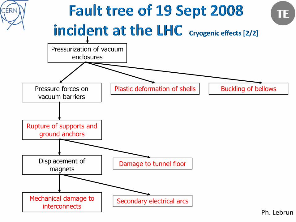
Pressurization of vacuum enclosures
Pressure forces on vacuum barriers
Plastic deformation of shells Buckling of bellows
Rupture of supports and ground anchors
Displacement of magnets
Mechanical damage to interconnects
Secondary electrical arcs
Damage to tunnel floor
Ph. Lebrun

Q1_R Q7_R Q11_R Q15_R Q19_R Q23_R Q27_R Q31_R Q33_R Q31_L Q27_L Q23_L Q19_L Q15_L Q11_L Q3_L
--> --> --> --> --> --> --> --> --> --> --> --> --> --> --> -->
Q3_R Q10_R Q14_R Q18_R Q22_R Q26_R Q30_R Q32_R Q32_L Q28_L Q24_L Q20_L Q16_L Q12_L Q7_L Q1_L
D1 A1 A1 A1 A1 A1 A2 A1 A1 A1 A1 A1 A1 D2
Q1_R Q7_R Q11_R Q15_R Q19_R Q23_R Q27_R Q31_R Q33_R Q31_L Q27_L Q23_L Q19_L Q15_L Q11_L
--> --> --> --> --> --> --> --> --> --> --> --> --> --> -->
Q3_R Q10_R Q14_R Q18_R Q22_R Q26_R Q30_R Q32_R Q32_L Q28_L Q24_L Q20_L Q16_L Q12_L Q7_L
D1 A1 A1 A1 A1 A1 A2 A1 A1 A1 A1 A1 A1 D2 D5
Q7_R Q11_R Q15_R Q19_R Q23_R Q27_R Q31_R Q33_R Q31_L Q27_L Q23_L Q19_L Q15_L Q11_L
--> --> --> --> --> --> --> --> --> --> --> --> --> -->
Q10_R Q14_R Q18_R Q22_R Q26_R Q30_R Q32_R Q32_L Q28_L Q24_L Q20_L Q16_L Q12_L Q7_L
D5 D1 A1 A1 A1 A1 A1 A2 A1 A1 A1 A1 A1 A1 D2
Q7_R Q11_R Q15_R Q19_R Q23_R Q27_R Q31_R Q33_R Q31_L Q27_L Q23_L Q19_L Q15_L Q11_L Q3_L
--> --> --> --> --> --> --> --> --> --> --> --> --> --> -->
Q10_R Q14_R Q18_R Q22_R Q26_R Q30_R Q32_R Q32_L Q28_L Q24_L Q20_L Q16_L Q12_L Q7_L Q1_L
D1 A1 A1 A1 A1 A1 A2 A1 A1 A1 A1 A1 A1 D2
Q1_R Q7_R Q11_R Q15_R Q19_R Q23_R Q27_R Q31_R Q33_R Q31_L Q27_L Q23_L Q19_L Q15_L Q11_L
--> --> --> --> --> --> --> --> --> --> --> --> --> --> -->
Q3_R Q10_R Q14_R Q18_R Q22_R Q26_R Q30_R Q32_R Q32_L Q28_L Q24_L Q20_L Q16_L Q12_L Q8_L
D1 A1 A1 A1 A1 A1 A2 A1 A1 A1 A1 A1 A1 D3
Q8_R Q11_R Q15_R Q19_R Q23_R Q27_R Q31_R Q33_R Q31_L Q27_L Q23_L Q19_L Q15_L Q11_L
--> --> --> --> --> --> --> --> --> --> --> --> --> -->
Q10_R Q14_R Q18_R Q22_R Q26_R Q30_R Q32_R Q32_L Q28_L Q24_L Q20_L Q16_L Q12_L Q7_L
D4 A1 A1 A1 A1 A1 A2 A1 A1 A1 A1 A1 A1 D2 D5
Q7_R Q11_R Q15_R Q19_R Q23_R Q27_R Q31_R Q33_R Q31_L Q27_L Q23_L Q19_L Q15_L Q11_L Q3_L
--> --> --> --> --> --> --> --> --> --> --> --> --> --> -->
Q10_R Q14_R Q18_R Q22_R Q26_R Q30_R Q32_R Q32_L Q28_L Q24_L Q20_L Q16_L Q12_L Q7_L Q1_L
D5 D1 A1 A1 A1 A1 A1 A2 A1 A1 A1 A1 A1 A1 D2
Q1_R Q7_R Q11_R Q15_R Q19_R Q23_R Q27_R Q31_R Q33_R Q31_L Q27_L Q23_L Q19_L Q15_L Q11_L Q3_L
--> --> --> --> --> --> --> --> --> --> --> --> --> --> --> -->
Q3_R Q10_R Q14_R Q18_R Q22_R Q26_R Q30_R Q32_R Q32_L Q28_L Q24_L Q20_L Q16_L Q12_L Q7_L Q1_L
D1 A1 A1 A1 A1 A1 A2 A1 A1 A1 A1 A1 A1 D2
DF
BX
I2 M3 M1 M1 D6 D6 M4 I1
DF
BA
DF
BA
DF
BL
Q6_L
Q5_L
Q4D
2_L
S8-1
DF
BX
D1_R
D2Q
4_R
DF
BM
DF
BM
Q5_R
DF
BM
Q6_R
DF
BX
M2 D7 M1 M3 I2
Q6_L
DF
BM
Q5_L
DF
BM
Q4D
2_L
D1_L
S7-8
DF
BM
Q6_R
DF
BA
DF
BA
DF
BA
DF
BM
Q6_L
M1 M1 D6 M2
S6-7
DF
BM
Q4_R
DF
BM
Q5_R
DF
BA
I1 M4 D6 D6 M1 M1
DF
BA
DF
BA
DF
BM
Q5_L
DF
BM
Q4_L
S5-6
DF
BX
D2Q
4_R
Q5_R
Q6_R
DF
BL
I1M1 M3 M1 D6 D6 M4
DF
BA
DF
BL
Q6_L
Q5_L
Q4D
2_L
DF
BX
S4-5
DF
BM
D3_R
D4Q
5_R
DF
BM
DF
BM
Q6_R
DF
BA
D3_L
M2 D8 D6 M1 M3 M1
DF
BA
DF
BM
Q6_L
DF
BM
Q5D
4_L
DF
BM
S3-4
DF
BM
Q6_R
DF
BLC
DS
LC
DF
BA
DF
BA
Q6_L
DF
BM
I2 M3 M1 D7 M2
S2-3
DF
BX
D1_R
D2Q
4_R
DF
BM
DF
BM
Q5_R
Q6_R
DF
BA
Q4D
2_L
D1_L
DF
BX
I1 M4 D6 D7 M1 M3 I2
DF
BA
DF
BA
Q6_L
DF
BM
Q5_L
DF
BM
S1-2
DF
BX
D2Q
4_R
Q5_R
Q6_R
DF
BL
Inner tripletInner triplet Maching sectionDispersion
suppressorArc
Dispersion
suppressorMatching section

080919 accident(~ 5 TeV)
With “smaller” electrical arc (i.e. lower magnetic stored energy and/or lower discharge time constant), perforation of the beam pipe can not be excluded with the present consolidation status. (Electrical insulation of the beam pipe interconnect foreseen in 2013/12)

• Mass flow MCI flow (already at 3.5 TeV, an electrical arc is able to create the MCI breaches ( 2 x 60 cm2)), e.g. 30 kg/s in the continuous cryostat.
0
10
20
30
40
50
60
70
80
90
100
0
200
400
600
800
1000
1200
1400
0 1 2 3 4 5 6 7 8
Dis
cha
rge
d h
eli
um
te
mp
era
ture
[K
]
Sto
red
ma
gne
tic
en
erg
y [M
J]
Beam energy [TeV]
Stored energy
Discharge temperature• Temperature of helium heated
by the electrical arc power and discharged through the safety devices depends on:• the stored magnetic
energy• The current discharge time
constant• The heat transferred by
convection from the environment.

Q6
R2
Lin
k Q
6R
2D
FBA
Mid
-arc
su
b-se
cto
r
DS
& D
FBA
DFB
AM
id-a
rc s
ub-
sect
or
DS
& D
FBA
Lin
k Q
6L8
Q6L
8
DFB
AM
id-a
rc s
ub-
sect
or
DS
& D
FBA
1
1.5
2
2.5
3
3.5
4
4.5
5
5.5
S1-2 S2-3 S3-4 S4-5 S5-6 S6-7 S7-8 S8-1
Max
imu
m v
acu
um
-en
clo
sure
pre
ssu
re [
bar
]
3.5 TeV
5 TeV
Maximum pressure of re-enforced fixed points
Vacuum-enclosure design pressure

Vacuum sub-sectorP max [bar]
Remarks3.5 TeV 5 TeV
Link Q6R2 & Q6L85.1 5.1
Compatible with vacuum enclosure design margin (DN200 link)
Q6R2 & Q6L8 1.8 1.8 Compatible with vacuum enclosure design margin
Mid-arc S2-3, S7-8 & S8-11.8 2.3*
Compatible with vacuum enclosure design margin and re-enforced fixed points on SSS
DFBA HCM R2, L3, R7 & L81.6 2.0
Compatible with vacuum enclosure design margin and re-enforced fixed points on DFBA
DFBA HCM R8 & L11.4 1.7
Compatible with vacuum enclosure design margin and re-enforced fixed points on DFBA
DS L3, L8 & L11.4 1.6
Compatible with vacuum enclosure design margin and re-enforced fixed points on SSS and DFBA
Conclusion: Up to 5 TeV, no longer mechanical collateral damages in adjacent sub-sectors!
*: Above 1.9 bar, plastic deformation of SSS vacuum barrier could occur(pressure test under preparation)

Electrical arc
Beam pipe perforationHe vessel perforation Soot
He discharge in insulation vacuum
Contamination by sootInadequate sizing of relief devices (MCI)
Pressurization of vacuum enclosures
Mechanical damage to MLI
Contamination by MLI
ODH in tunnelBlast
Trip AUG
Loss of beam vacuum
Break vent door
Ph. LebrunInstrumentation flange opening on
temporary consolidated sectors
Mechanical damage of instrumentation cabling

• Sept’08 damages which are mitigated by the 2009 consolidations:– Plastic deformation of shells– Buckling of bellows– Rupture of supports and ground anchors– Damage to tunnel floor– Mechanical damage to interconnects– Secondary electrical arcs
• Damages still present up to 5 TeV– He vessel and beam pipe perforation– Mechanical damage of MLI– Contamination by soot of MLI and beam pipes– Contamination by MLI of vacuum enclosure and beam pipes– Mechanical damage of BPM cabling

PTQVQV QVQV SVSV
Cold-massVacuum vesselLine ECold support postWarm JackCompensator/BellowsVacuum barrier
Q D D QD D D QD D D QD D D QD
PTQVQV SV
Q D D QD D D QD
He vessel perforation
Mechanical damage of MLI
Contamination of MLI by soot & of vacuum enclosure by MLI
Contamination of beam pipe(s) by soot
BD
Contamination of beam pipe(s) by MLI(over the whole continuous cryostat length)Length to be removed and re-installed (~12 dipoles + ~4 SSS)
BDBD BD BD BD BD BD BD BD BD BD BD BD BD BD BD BD
PTQVQV QVQV SVSV
Q D D QD D D QD D D QD D D QD
PTQVQV SV
Q D D QD D D QD
He vessel perforation
Mechanical damage of MLI
Contamination of MLI by soot & of vacuum enclosure by MLI
Contamination of beam pipe(s) by soot
BD
Contamination of beam pipe(s) by MLI(over the whole continuous cryostat length)
Length to be removed and re-installed (~14 dipoles + ~4 SSS)
BDBD BD BD BD BD BD BD BD BD BD BD BD BD BD BD BD
To be exchanged or repaired (surface) before operation restart
To be repaired in-situ before operation restart
Consolidation can wait the next long shut-down
Electrical arc position
Electrical arc in the middle of a subsector
Electrical arc closed to a vacuum barrier
Mechanical damage of instrumentation cabling
Mechanical damage of instrumentation cabling

• Without MLI, cold mass enclosure are not protected against pressure build-up in case of break of the insulation vacuum with air.
Heat transfer by condensation of air on cold wall
• From a calculation by Nusselt
– h ≈ 0.943 (r2 g k3 Lv/h x DT)0.25
• Assimilating air to nitrogen
– h ≈ 680 W/m2 K
– heat flux h DT ≈ 50’000 W/m2
– average thickness of film ≈ 0.2 mm
• Multi-layer insulation
– take e = 10 mm
• Conduction in solid nitrogen
– conductivity integral from 77 to 4 K ≈ 50 W/m
– Heat flux h DT ≈ 5’000 W/m2
LHeAir
Liquid air film, falling
x
Heat transport limited by conduction across falling film
LHeAir
Liquid air film, falling
Solid air trapped between MLI layers
e
Heat transport limited by conduction across solid air
Bare wall with MLI
Not compatible with the cold-mass pressure relief system !
Ph. Lebrun

• S3-4 incident: ~ 2/3 of the total affected length (22 cryo-magnets over 2 sub-sectors)
• New incident ?:– MLI damage goes with rv2 or m2/r or m2T/P
• S3-4 incident 30 kg/s – 6 bar – 70 K• New incident 3.5 TeV: 30 kg/s – 1.1 to 1.3 bar – 40 K factor 3 to 2.6• New incident 5 TeV: 30 kg/s – 1.1 to 1.5 bar – 60 K factor 4.5 to 3.5
– But the distribution of the safety devices allows a faster decrease of the flow along the length
– Let’s assume the same damage ratio (2/3) for a new incident i.e.: • ~ 10/16 cryo-magnets to be repaired use of spares for dipoles re-cryostating of SSS (no spare)
– Question: Can we safely operate with only missing MLI on SSS? (if yes, the heavy SSS re-cryostating could wait the next long shutdown!)

• Experience return from S3-4– V1 more representative (not burst disk opening)– In V1 about 600 m contaminated with soot– Pressurization: up to 3.5 bar
V1V2
~600 m
~400 m
• New incident expectation: Affected length is assumed to be proportional to the quantity of soot introduced:• For most sub-sectors, pressurization limited to 1.1-1.5 bar: quantity of soot introduced in the beam pipes divided by 2.3 to 3 250 to 200 m of magnet could be affected
• For the specific mid-arc subsectors (3/8), pressurization limited to 1.8 -2.3 bar: quantity of soot introduced in the beam pipe divided by 2 to 1.5 300 to 400 m of magnet could be affected
M. Jimenez

months
weeks 1 2 3 4 5 6 7 8 9 10 11 12 13 14 15 16 17 18 19 20 21 22 23 24 25 26 27 28 29 30 31 32
Sector warm-up (4 weeks)
Prepare spare dipoles (12 to 14) (1 week of preparation + 2 dipoles per week)
removal of SSS (4) (2 weeks of preparation + 2 SSS per week)
removal of dipole (12 to 14) (3 dipoles per week)
Recryostating of SSS for MLI(2 to 3) (4 weeks per SSS with overlap of 2 weeks)
Beam tube and BS cleaning of SSS (3 to 4) (1 SSS per week)
New SSS assembly (0 to 1) (2 weeks of preparation + 3 months)
Reinstallation (12-14 dipoles + 4 SSS) (3 months)
Opening of IC and PIMS (sector wide) (4 weeks)
BS MLI cleaning (1 shift) (3 months)
Reclosing of IC (sector wide) (4 weeks)
Sector recooldown (including cryo-tunning) (6 weeks)
Sector ELQA and HWC (4 weeks)
New DFBA assembly
7 81 2 3 4 5 6
Remark: In case of a hypothetical electrical arc in an Inner Triplet, soot contamination of the detector beam pipe cannot be excluded (Fast shutter valves installation only in 2013/12 long shutdown) Long and heavy repair work if NEG coatings are damaged! (4 to 6 months)

Electrical arc in a magnet cold mass
Beam pipe perforationMagnet quench Soot ?*
Pressurization of CM
Contamination by soot ?*
ODH in tunnel
Pressurization of beamvacuum
Beam pipe rupture disk opening
Mechanical damage of bellows (Nested & PIMs)
*Not seen during the “Noell 4”Incident in SM18

Complementary solutions to improve the beam vacuum protection and to protect sensitive
equipments (RF, kickers, experiments,…) J.M. Jimenez – LHC MAC April’10.
Mitigation solutions
Rupture disks (3/4)
Max. pressure (quench valve)
Adjusted level at 10 bars (quench valve)
Nested bellows buckling
PIM bellows buckling
C. Garion

0
2
4
6
8
10
12
14
16
18
0 1 2 3 4 5
Ma
xim
um
pre
ssu
re [b
ar]
Beam energy [TeV]
tc - 100 s
tc - 50 sNested bellows buckling
PIM bellows buckling
Working line ?
KC. WuR. van Weelderen
S. Claudet

• Beam pipe perforation of a single magnet (Reminder: the downtime for a single dipole exchange is about 4 months)
• Plastic deformation (rupture ?) of nested & PIM bellows:– No damage at 3.5 TeV (with 50 s time constant)
– Could become critical above 3.5 TeV especially if we increase the discharge time constant.• PIMs can be repaired in-situ
• Nested bellow repair requires magnet removal.

• Electrical arc in an interconnect:– The present consolidation, up to 5 TeV, will suppress mechanical
collateral damages in adjacent sub-sectors.– Nevertheless, mechanical damage of the MLI in the concerned sub-
sector as well as contamination of the beam pipe(s) could require heavy repair work.
– With the present consolidation status, a new incident will still have big impact on the machine down time (8 to 12 months)
• Electrical arc in a dipole coil:– Limited impact at 3.5 TeV (but at least 4 months of downtime to
exchange one dipole)– Could be more critical above 3.5 TeV (damage of bellows over several
sub-sectors)
• A hypothetical incident caused by an electrical arc during the 2011/12 operation could seriously impact the LHC physics program: Corresponding risks must be carefully assessed.