Launch Vehicle Avionics Passive Thermal … International Conference on Environmental Systems Paper...
12
44th International Conference on Environmental Systems Paper Number ICES-2014-262 13-17 July 2014, Tucson, Arizona Launch Vehicle Avionics Passive Thermal Management William G. Anderson 1 , Cameron Corday 2 , Mike DeChristopher 3 , John R. Hartenstine 4 , Taylor Maxwell 5 , Carl Schwendeman 6 , and Calin Tarau 7 Advanced Cooling Technologies, Inc., Lancaster, PA 17601 U.S.A. A passive thermal management system was designed to cool avionics on a launch vehicle for 3 different thermal modes. Prior to launch, the heat sink for the avionics is purge duct flow. During the 10 minute launch period, the thermal energy is stored in phase change material (PCM). On orbit, the heat sink is a radiator. The system consists of 1. A high conductivity thermal shelf, 2. A PCM thermal storage system, 3. Heat pipes to conduct the heat from the shelf to the heat sinks, 4. Fins to reject the heat to the purge duct, and 5. A radiator to reject the heat on orbit. A unique aspect of the system design is the avionics shelf, which contains embedded heat pipes. While the electronics locations are fixed before manufacturing with encapsulated high conductivity material, this design allows the avionics boxes to be positioned anywhere. A second benefit is the much higher thermal effective thermal conductivity, which can approach 2500 W/m K in long systems. A low-cost, simplified version of the system to fabricated to verify the design during ground testing, consisting of the high conductivity plate, the heat pipe, and the purge duct sink. The general performance matched expectations, except that the overall ΔT was higher than expected, due to the thermal interface materials. This can be improved with a better material. I. Introduction ASA Marshall Space Flight Center requested a design for a passive thermal management system to cool avionics on a launch vehicle. As shown in Figure 1 and Figure 2, there are a series of aluminum shelves with avionics boxes. Parameters for the system are shown in Table 1. Any combination of minimum, average, and maximum size boxes can be placed anywhere on the shelf, as long as the maximum power (500 W) for the shelf is not exceeded. There are three different thermal modes: 1. Cooling for avionics while on ground prior to launch (indefinitely) 2. Cooling for avionics during launch (~10min) 3. Cooling on-orbit (indefinitely) In pre-launch a nitrogen purge duct serves as the heat sink (~19.4°C) for the thermal control device. The purge duct is located above the avionics, and along with the passive thermal system, must maintain the avionics boxes within the safe operating temperature range (-6.6 to 25.5°C). At lift-off the nitrogen purge ceases. The energy produced by the electronics during the ascent period of ~10 minutes must be stored. Finally, the heat generated on orbit must be rejected to space using an external radiator. II. Thermal Management Subsystems The thermal management system has 4 distinct subsystems: 1 Chief Engineer, 1046 New Holland Ave. [email protected] 2 Engineer, Defense Aerospace Group, 1046 New Holland Ave. 3 Lead Engineer, Defense Aerospace Group, 1046 New Holland Ave. 4 Vice President, Operations, 1046 New Holland Ave. 5 Engineer, Defense Aerospace Group, 1046 New Holland Ave. 6 Engineer, Defense Aerospace Group, 1046 New Holland Ave. 7 Lead Engineer, Defense Aerospace Group, 1046 New Holland Ave. N
Transcript of Launch Vehicle Avionics Passive Thermal … International Conference on Environmental Systems Paper...
44th International Conference on Environmental Systems Paper Number ICES-2014-262 13-17 July 2014, Tucson, Arizona
Launch Vehicle Avionics Passive Thermal Management
William G. Anderson1, Cameron Corday2, Mike DeChristopher 3, John R. Hartenstine 4, Taylor Maxwell5, Carl Schwendeman 6, and Calin Tarau7
Advanced Cooling Technologies, Inc., Lancaster, PA 17601 U.S.A.
A passive thermal management system was designed to cool avionics on a launch vehicle for 3 different thermal modes. Prior to launch, the heat sink for the avionics is purge duct flow. During the 10 minute launch period, the thermal energy is stored in phase change material (PCM). On orbit, the heat sink is a radiator. The system consists of 1. A high conductivity thermal shelf, 2. A PCM thermal storage system, 3. Heat pipes to conduct the heat from the shelf to the heat sinks, 4. Fins to reject the heat to the purge duct, and 5. A radiator to reject the heat on orbit. A unique aspect of the system design is the avionics shelf, which contains embedded heat pipes. While the electronics locations are fixed before manufacturing with encapsulated high conductivity material, this design allows the avionics boxes to be positioned anywhere. A second benefit is the much higher thermal effective thermal conductivity, which can approach 2500 W/m K in long systems. A low-cost, simplified version of the system to fabricated to verify the design during ground testing, consisting of the high conductivity plate, the heat pipe, and the purge duct sink. The general performance matched expectations, except that the overall ΔT was higher than expected, due to the thermal interface materials. This can be improved with a better material.
I. Introduction ASA Marshall Space Flight Center requested a design for a passive thermal management system to cool avionics on a launch vehicle. As shown in Figure 1 and Figure 2, there are a series of aluminum shelves with
avionics boxes. Parameters for the system are shown in Table 1. Any combination of minimum, average, and maximum size boxes can be placed anywhere on the shelf, as long as the maximum power (500 W) for the shelf is not exceeded. There are three different thermal modes:
1. Cooling for avionics while on ground prior to launch (indefinitely) 2. Cooling for avionics during launch (~10min) 3. Cooling on-orbit (indefinitely)
In pre-launch a nitrogen purge duct serves as the heat sink (~19.4°C) for the thermal control device. The purge duct is located above the avionics, and along with the passive thermal system, must maintain the avionics boxes within the safe operating temperature range (-6.6 to 25.5°C). At lift-off the nitrogen purge ceases. The energy produced by the electronics during the ascent period of ~10 minutes must be stored. Finally, the heat generated on orbit must be rejected to space using an external radiator.
II. Thermal Management Subsystems The thermal management system has 4 distinct subsystems:
1 Chief Engineer, 1046 New Holland Ave. [email protected] 2 Engineer, Defense Aerospace Group, 1046 New Holland Ave. 3 Lead Engineer, Defense Aerospace Group, 1046 New Holland Ave. 4 Vice President, Operations, 1046 New Holland Ave. 5 Engineer, Defense Aerospace Group, 1046 New Holland Ave. 6 Engineer, Defense Aerospace Group, 1046 New Holland Ave. 7 Lead Engineer, Defense Aerospace Group, 1046 New Holland Ave.
N

International Conference on Environmental Systems
2
1. A heat collection system to collect the heat from the electronics boxes, and deliver it to a heat pipe 2. A thermal storage system, to accept the heat generated during ascent 3. A heat rejection system. On the ground, the heat is rejected through a series of fins to the purge air. On
orbit, the heat is rejected with a radiator. 4. A heat transport system, consisting of riser heat pipes that transfer heat from the avionics shelf to the heat
sink.
Figure 1: Purge Duct and Avionics Boxes
Figure 2: Purge duct routing concept
A. Heat Collection If the heat source locations are known, then heat pipes could be designed to carry heat directly from the heat
sources to the riser heat pipes. However, the electronics boxes (and heat sources) can be located anywhere on the shelves. In this case, the shelf must be designed with a high effective thermal conductivity. There are two options:
1. Encapsulated conduction cooling plates 2. High conductivity plates with embedded heat pipes.
1. Encapsulated Conduction Cooling Plates The thermal conductivity of aluminum is about 200 W/m K. While copper has double the thermal conductivity,
it is not used because its specific thermal conductivity is less than aluminum. Some metal composites and pyrolytic graphite have higher conductivities, but cannot be used by themselves, since they are often brittle, hygroscopic, and/or have relatively low strength. To minimize these problems, encapsulated conduction cooling plates have been
International Conference on Environmental Systems
3
developed. A core of high conductivity material is encapsulated in a metallic shell to provide protection and strength.
Table 1. Global Design Goals.
Temperatures Baseplate Allowable Temperature Range -6.6 to 25.5°C Purge Duct Nitrogen Sink 19.4 °C
Purge Duct Aluminum, wall thickness: 1.6 mm (0.063 in.) Purge Duct Diameter 10 to 25 cm (4 to 10 in.) Purge Duct Length 20 to 96 cm (12 to 48 in.)
Purge Duct Flow 8.5 to 51 m3/min (300 to 1800 cfm)
Purge Flow Pressure Drop in Fin Stack 690 Pa (0.1 psid)/per shelf Avionics Shelf
Maximum power per shelf 500 W Shelf Length 152 cm (60 in.) Shelf Width 46 cm (18 in.) Shelf Thickness 3.8 cm (1.5 in.)
Avionics Boxes Maximum Power per box 175 W Maximum (Width x Depth x Height) 50 x 30 x 30 cm (20 x 12 x 12 in.) Average 30 x 30 x 30 cm (12 x 12 x 12 in.) Minimum 15 x 25 x 15 cm (6 x 10 x 6 in.)
Encapsulated pyrolytic graphite plates have been used in spacecraft applications. While the in-plane thermal
conductivity of pyrolytic graphite is 1000 to 1500 W/m K, the out-of-plane thermal conductivity is only 10 W/m K. Aluminum thermal vias are required to provide an interface between high heat flux components and the pyrolytic graphite. These locations are fixed during encapsulation, and lower the effective thermal conductivity. Due to the effects of the thermal vias, independent measurements have documented thermal conductivities around 550W/m-K with an aluminum encapsulant (Kugler, 2008). Encapsulated pyrolytic graphite is also expensive to manufacture, and the thermal conductivity drops after several hundred thermal cycles, as the encapsulant moves relative to the thermal vias. One set of tests reported that the effective conductance dropped by up to 12% (8% average) after ~220 thermal cycles between 100°C and -40°C. (Montesano, 2005)
Encapsulated pyrolytic graphite plates were dropped from further consideration due to: • Expense. The parts must be hot isostatically pressed. • Thermal conductivity: 550 W/m K is much lower than can be achieved with embedded heat pipes • Fixed heat source locations. The via locations must be chosen prior to fabrication, which conflicts with
the requirement to locate the boxes anywhere on the shelf.
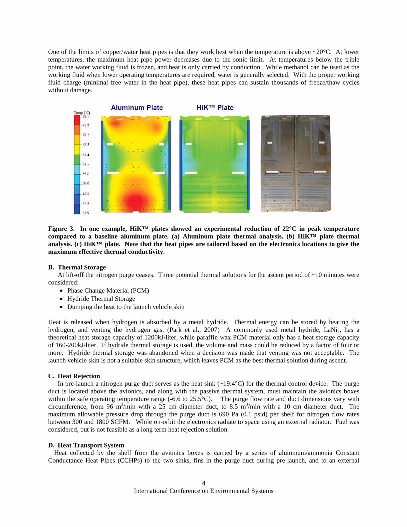
2. High Conductivity (Hi-K) Plates with Embedded Heat Pipes High conductivity (HiK™) plates are aluminum plates with embedded heat pipes to increase the effective
thermal Conductivity (Advanced Cooling Technologies, 2014) They are used in terrestrial cooling systems to collect heat from electronics, and either spread the heat or conduct it to a cold rail for cooling. A typical HiK plate has copper/water heat pipes embedded in a standard aluminum plate, using epoxy or solder; see Figure 3. The heat pipes are strategically placed to get good thermal results while not affecting current geometry or mounting features. The heat pipes and solder weigh slightly more than an aluminum baseplate (1.1 to 1.2 times more), but have effective thermal conductivities of 600 to 1200 W/m K for terrestrial systems, which is 3 to 6 times higher than aluminum. For longer, spaced-based systems, the effective thermal conductivity can be as high as 2500 W/m K, which is better than diamond. HiK™ plates can also be used as structural components within systems.
International Conference on Environmental Systems
4
One of the limits of copper/water heat pipes is that they work best when the temperature is above ~20°C. At lower temperatures, the maximum heat pipe power decreases due to the sonic limit. At temperatures below the triple point, the water working fluid is frozen, and heat is only carried by conduction. While methanol can be used as the working fluid when lower operating temperatures are required, water is generally selected. With the proper working fluid charge (minimal free water in the heat pipe), these heat pipes can sustain thousands of freeze/thaw cycles without damage.
Figure 3. In one example, HiK™ plates showed an experimental reduction of 22°C in peak temperature compared to a baseline aluminum plate. (a) Aluminum plate thermal analysis. (b) HiK™ plate thermal analysis. (c) HiK™ plate. Note that the heat pipes are tailored based on the electronics locations to give the maximum effective thermal conductivity.
B. Thermal Storage At lift-off the nitrogen purge ceases. Three potential thermal solutions for the ascent period of ~10 minutes were considered:
• Phase Change Material (PCM) • Hydride Thermal Storage • Dumping the heat to the launch vehicle skin
Heat is released when hydrogen is absorbed by a metal hydride. Thermal energy can be stored by heating the hydrogen, and venting the hydrogen gas. (Park et al., 2007) A commonly used metal hydride, LaNi5, has a theoretical heat storage capacity of 1200kJ/liter, while paraffin wax PCM material only has a heat storage capacity of 160-200kJ/liter. If hydride thermal storage is used, the volume and mass could be reduced by a factor of four or more. Hydride thermal storage was abandoned when a decision was made that venting was not acceptable. The launch vehicle skin is not a suitable skin structure, which leaves PCM as the best thermal solution during ascent.
C. Heat Rejection In pre-launch a nitrogen purge duct serves as the heat sink (~19.4°C) for the thermal control device. The purge
duct is located above the avionics, and along with the passive thermal system, must maintain the avionics boxes within the safe operating temperature range (-6.6 to 25.5°C). The purge flow rate and duct dimensions vary with circumference, from 96 m3/min with a 25 cm diameter duct, to 8.5 m3/min with a 10 cm diameter duct. The maximum allowable pressure drop through the purge duct is 690 Pa (0.1 psid) per shelf for nitrogen flow rates between 300 and 1800 SCFM. While on-orbit the electronics radiate to space using an external radiator. Fuel was considered, but is not feasible as a long term heat rejection solution.
D. Heat Transport System Heat collected by the shelf from the avionics boxes is carried by a series of aluminum/ammonia Constant
Conductance Heat Pipes (CCHPs) to the two sinks, fins in the purge duct during pre-launch, and to an external

International Conference on Environmental Systems
5
radiator on orbit. Depending on the mission, it may be necessary to use Variable Conductance Heat Pipes (VCHPs) to keep the electronics above 6.6°C in certain orbits.
III. System Design The overall thermal management system, shown in Figure 4, has the following components: • High Conductivity (HiK™) Plate, where the avionics are mounted • Three Constant Conductance Heat Pipe (CCHP) Header Heat Pipes • Finned Heat Exchanger, the designated heat sink during pre-launch. • Phase Change Material, the designated heat sink during ascent. • Radiator, the designated heat sink on orbit.
Figure 4. Thermal management system for a single avionics shelf.
The purge duct temperature would need to be reduced slightly for this concept, since it requires the avionics boxes
to operate below the melting temperature of the PCM during pre-launch and then rise above the melting temperature during launch. With the current ΔT of ~6.1°C between the maximum allowable electronics temperature and the purge flow sink, this is difficult to achieve. The problem can be alleviated by slightly reducing the purge sink temperature during pre-launch, and/or operating the avionics slightly above their maximum allowable temperature during the 10 minute launch period. Since cost and feasibility were considered dominant factors of the design, a request for such changes in the design requirements was considered reasonable.
Figure 5: Partial Hi-K plate model used in thermal analysis
International Conference on Environmental Systems
6
E. Avionics Shelf Design The Hi-K plate geometry used throughout the thermal analysis consisted of a 50.8 x 45.7 x 0.64 cm (20 x 18 x
0.25 in.) 6061 aluminum plate. The one-third plate module has a total of 51 fully embedded copper/water heat pipes (OD = 0.635 cm (0.25 in), average length = 28.6 cm (11.25 in), wall thickness = 0.51 mm (0.02 in)) in a spreading pattern. The partial assembly also has an aluminum/ammonia CCHP header (OD = 2.54 cm (1in)) with flange width of 6.35 cm (2.5 in) and a flange thickness of 3.2 mm (0.125 in.).
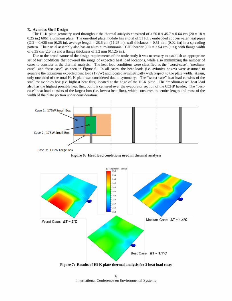
Due to the broad nature of the design requirements of the trade study it was necessary to establish an appropriate set of test conditions that covered the range of expected heat load locations, while also minimizing the number of cases to consider in the thermal analysis. The heat load conditions were classified as the “worst-case”, “medium-case”, and “best case”, as seen in Figure 6. In all cases, the heat loads (i.e. avionics boxes) were assumed to generate the maximum expected heat load (175W) and located symmetrically with respect to the plate width. Again, only one third of the total Hi-K plate was considered due to symmetry. The “worst-case” heat load consists of the smallest avionics box (i.e. highest heat flux) located at the edge of the Hi-K plate. The “medium-case” heat load also has the highest possible heat flux, but it is centered over the evaporator section of the CCHP header. The “best-case” heat load consists of the largest box (i.e. lowest heat flux), which consumes the entire length and most of the width of the plate portion under consideration.
Figure 6: Heat load conditions used in thermal analysis
Figure 7: Results of Hi-K plate thermal analysis for 3 heat load cases

International Conference on Environmental Systems
7
Figure 7 shows the results of the numerical analysis performed with Autodesk CFD Simulation for the three heat load scenarios for the optimized Hi-K plate design. The low temperature boundary condition (represented as the vapor temperature of the CCHP header) was assumed to be at ~23.3°C and located at the cut surface of the CCHP header.
The primary interest of this analysis was the temperature differences between the heat loads and the CCHP vapor; since this quantity dictates the remaining delta T that will be available to transport the heat load to the purge duct sink. The temperature difference was ~2.0°C for the “worst-case” scenario, ~1.4°C for the “medium-case” scenario, and ~1.1°C for the “best-case” scenario. These results indicate that there will be at least a ~4.1°C temperature difference to facilitate heat transfer from the CCHP header to the purge duct sink using the most conservative estimate.
F. Heat Sink during Launch – Phase Change Materials (PCM) In order to prevent the avionics from over-heating during launch a heat sink must be able to accept 500W of heat
from a shelf for ~10 minutes (i.e. 300kJ). PCM was selected as the heat sink during launch. A trade study on various phase change materials was conducted to help with the material selection process. The salt hydrate material (Rubitherm, SP25A08) was chosen primarily because the melting temperature of the material (25°C)was near the avionics operating temperature and the latent heat of fusion was reasonably large (160 kJ/kg).
The PCM mass is relatively small and the PCM was spread over half of the bottom of each one-third of the shelf, centered around the header heat pipes. The conductivity was enhanced with aluminum fins, each 0.5 mm (0.020 in.) thick, 5.7 mm (0.225 in.) with a PCM thickness of 2 mm (0.080 in.).
G. System Mass The mass breakdown for a single avionics shelf is given in Table 2.
Table 2. System mass for a single avionics shelf.
Component Description Component Mass (kg) Quantity
Mass (kg)
Al Hi-K Plate (0.25") 7.38 1 7.38 Embedded Cu Pipes 0.06 153 9.18 Embedded Ti Pipes 0.02 153 3.06 Al/NH3 CCHP Header 1.09 3 3.27 Total PCM Package 0.93 3 2.80 Al Finned Stack (for duct) 300CFM 0.40 3 1.21 Al Finned Stack (for duct) 1800CFM 0.49 3 1.48 Radiator Panel 13.50 1 13.50 Embedded Al Pipes for Radiator NA 20 3.60 Total Mass w/ Cu Pipes (kg) 42.42 Total Mass w/ Ti Pipes (kg) 36.30
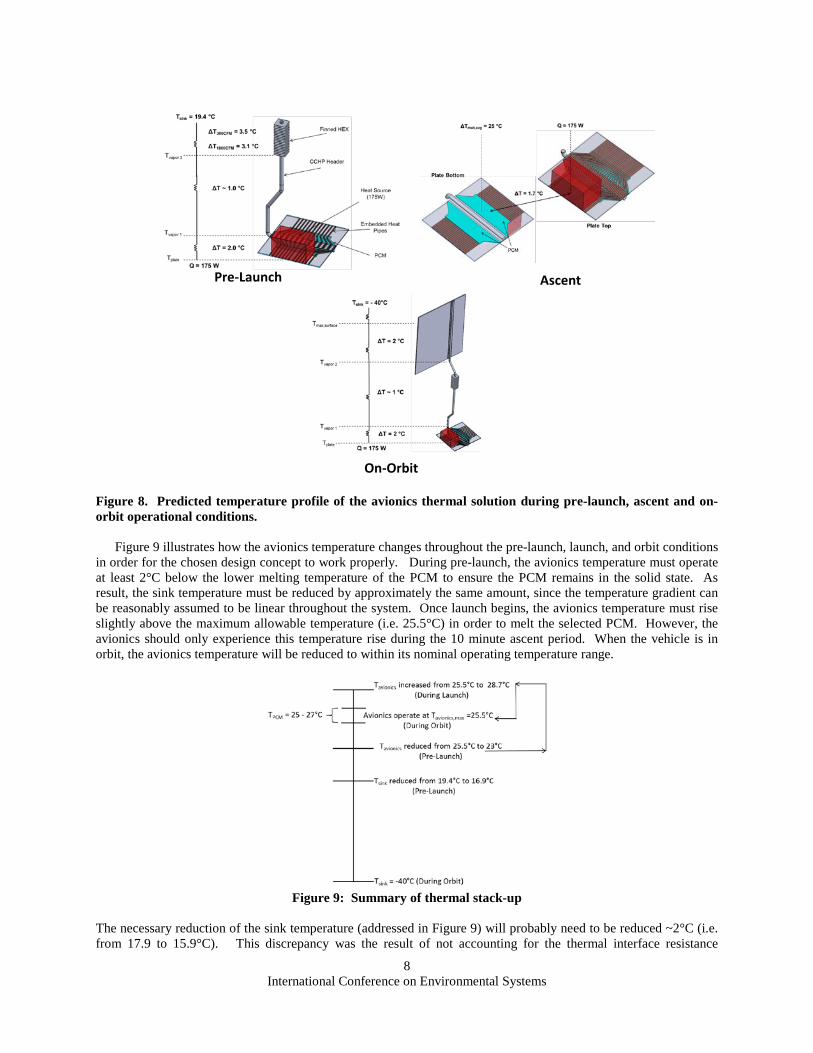
IV. Thermal Stackup The thermal stackup of the system during pre-launch, launch, and on-orbit is shown in Figure 8. The pre-launch
ΔT stackup is for the “worse-case” heat loading condition. For this case, the ΔTs for both the 300 and 1800CFM purge flow conditions are included. A temperature drop of 1°C was assumed for the vapor within the CCHP header; however, this was a conservative estimate since the heat pipe vapor is usually considered isothermal.
The upper right area of Figure 8 shows the layout of the PCM and the corresponding temperature drop between the avionics and PCM for the “worse-case” heat loading condition. This figure indicates that the avionics operating temperature would need to exceed the maximum allowable temperature (~25.5°C) in order to completely melt the selected PCM. The lower section of Figure 8 shows the thermal stack-up for on orbit conditions. The stack-up is based on the “worse-case” heat load condition and the highest expected sink temperature.
International Conference on Environmental Systems
8
Pre-Launch Ascent
On-Orbit
Figure 8. Predicted temperature profile of the avionics thermal solution during pre-launch, ascent and on-orbit operational conditions.
Figure 9 illustrates how the avionics temperature changes throughout the pre-launch, launch, and orbit conditions in order for the chosen design concept to work properly. During pre-launch, the avionics temperature must operate at least 2°C below the lower melting temperature of the PCM to ensure the PCM remains in the solid state. As result, the sink temperature must be reduced by approximately the same amount, since the temperature gradient can be reasonably assumed to be linear throughout the system. Once launch begins, the avionics temperature must rise slightly above the maximum allowable temperature (i.e. 25.5°C) in order to melt the selected PCM. However, the avionics should only experience this temperature rise during the 10 minute ascent period. When the vehicle is in orbit, the avionics temperature will be reduced to within its nominal operating temperature range.
Figure 9: Summary of thermal stack-up
The necessary reduction of the sink temperature (addressed in Figure 9) will probably need to be reduced ~2°C (i.e. from 17.9 to 15.9°C). This discrepancy was the result of not accounting for the thermal interface resistance

International Conference on Environmental Systems
9
between the CCHP header flange and the Hi-K plate in the thermal analysis of the Hi-K plate. The requirement for the increase in avionics temperature during launch should not be affected by this discrepancy, since the CCHP header can be assumed to be inactive during this time; hence the delta T of the interface will be insignificant.
V. Experimental Design and Fabrication A low-cost, simplified version of the system was fabricated to verify the design during ground testing. It
consisted of: • High Conductivity Plate, or embedded heat pipe HiK plate. • Associated header heat pipe with appropriate interfaces on the condenser end to transport collected heat to
externally provided heat sinks that simulate either ground cooling or in-space cooling. • Removable Purge Flow Fin Heat Exchanger (ranging from modular fins for duct cooling with a flange for
attachment to a radiator to a flange only to support a variety of heat rejection methods). Design requirements for the system are given in Table 3. It is one-third of the complete avionics shelf, with one heat pipe.
Figure 10. Heat Sink in Duct.
Table 3. Test Rig Design Requirements.
Avionics HiK Shelf Heat Load 175 W Avionics Max. Heat Flux Density 0.51 W/cm2 (3.3 W/in2) Maximum Avionics Surface Temperature 26°C Avionics Shelf 50.8 x 45.7 cm (20 x 18 in.) Bolt hole pattern for avionics boxes 2 in. x 2 in. bolt hole pattern
Heat Sink
Flow Rate 8.5 m3/min (300 scfm) Purge Flow Temperature 18 C Duct Diameter 10.2 cm (4 inch) Maximum pressure drop 690 Pa (0.1 psid) Heat Exchanger (Duct Length) Less than 30.5 cm (12 in.) Vertical Distance for Heat Transport 122 cm (48 in.)

International Conference on Environmental Systems
10
The HiK plate has 36 embedded heat pipes. The copper/water heat pipes were flattened to fit in the plate, with an
initial O.D. of 6.35 mm (0.25 in.) As shown in Figure 11, the heat pipes are laid out to avoid the mounting bolt holes.
Figure 11. HiK Plate Instrumentation. The locations of the straight heat pipes embedded in the plate can be seen.
VI. Preliminary Testing Preliminary tests were conducted at ACT to verify functionality and to correlate the experimental data with the models. The experimental test setup is shown in Figure 12 and Figure 12. Electrical heaters applied 175 W (0.51 W/cm2) over a 7.6 x 35.7 cm (3 x 18 in.) strip at the edge of the plates (worst case).
TC 19
TC 21
TC 12
TC 22
Figure 12. HiK Plate/CCHP/Heat Sink/Duct test set-up.

International Conference on Environmental Systems
11
Figure 13. With the CCHP evaporator located in the center of the plate. 175 W (0.51 W/cm2) was applied over a 7.6 x 35.7 cm (3 x 18 in.) strip at the edge of the plates.
Table 4. Preliminary Experimental Test Results.
Test 1 Test 2 HiK Plate to Heat Pipe 5.87°C 5.58°C Heat Pipe Length 2.69°C 2.56°C Heat Pipe to Air 6.58°C 6.34°C Overall, Plate Surface to Air 15.13°C 14.40°C
Tests results are shown in Table 4. The high level goal for this program is to develop an avionics thermal
management system with an overall thermal gradient of near 6°C. The low-cost proof of concept system developed under this program demonstrated that certain elements of the total system stack up are conducive to a 6°C system. The header CCHP performed in both the reflux and 0.1” adverse tilt orientation with only a 2.7°C gradient. Much of the overall ΔT is due to the thermal interface materials (TIMs), between the HiK plate and the CCHP, and the CCHP and the Heat Sink.
The TIM was Nusil CV2-2646 for all the make/break joints. This is a low outgassing RTV silicone, with a thermal conductivity of 1.50 W/m K. The measured ΔT of roughly 15°C was above the predicted value of 13.5°C.
For this assembly, the individual components were designed to be disconnected readily from one another. Alternate thermal interface materials are commercially available that would result in a higher thermally conductive interface with added difficultly for disassembly. A common flight adhesive is Eccobond 56C with Cat 9. This product is a two part silver filled epoxy. The finned heat exchanger was designed based on commercially available off the shelf extrusion stock. A higher efficiency, custom design could be developed and machined to reduce the gradient between the nitrogen and the header heat pipe. An optimized fin thickness, fin height, and fin length could be developed to improve the efficiency of the heat exchanger. Additionally, embedded heat pipe technology could also be employed to further isothermalize the heat exchanger.
After preliminary testing at ACT for functional testing and model correlation, the assembly was delivered to Marshall Space Flight Center for subsequent integrated system level testing in ambient and thermal vacuum conditions at MSFC.
VII. Conclusion A passive thermal management system was designed to cool avionics on a launch vehicle for 3 different thermal
modes 1. Cooling for avionics while on ground prior to launch (indefinitely), dumping the heat to flow in a purge duct. 2. Cooling for avionics during launch (~10min), storing the heat in a PCM module 3. Cooling on-orbit (indefinitely), with a radiator.
The system has the following components
• High Conductivity (HiK™) Plate with embedded heat pipes, where the avionics are mounted • Three Constant Conductance Heat Pipe (CCHP) Header Heat Pipes, that transfer heat to the purge duct of the
radiator

International Conference on Environmental Systems
12
• Finned Heat Exchangers, the designated heat sink during pre-launch. • PCM modules, the designated heat sink during ascent. • Radiator, the designated heat sink on orbit.
A unique aspect of the system design is the avionics shelf, which contains embedded heat pipes. While the electronics locations are fixed before manufacturing with encapsulated high conductivity material, this design allows the avionics boxes to be positioned anywhere. A second benefit is the much higher thermal effective thermal conductivity, which can approach 2500 W/m K in long systems. A low-cost, simplified version of the system (one of three modules) was designed and fabricated to verify the design during ground testing. It consisted of the HiK plate, the heat pipe from the plate to the simulated duct, and a simple, low cost heat sink inside of the simulated duct. The measured ΔT of roughly 15°C was above the predicted value of 13.5°C, due to the thermal interface material, which was chosen for easy disassembly. The overall thermal performance can be improved with a better interface material.
Acknowledgments This project was sponsored by NASA Marshall Space Flight Center under Purchase Order Numbers 00096797
and NNM13AE60P. The Technical Monitor was Dr. Jeffery T. Farmer.
References 1Advanced Cooling Technologies, Inc., “High Conductivity, or HiK™ Plates”, http://www.1-act.com/hik-plates-2/, accessed
March 10, 2014. S. Kugler, “Aluminum Encapsulated APG High Conductivity Thermal Doubler” Spacecraft Thermal Control Workshop, El
Segundo, CA, March 11-13, 2008. M. Montesano, “Conduction Cooled Module Trade-off Study and Qualification,” Spacecraft Thermal Control Workshop, El
Segundo, CA, March 9-11, 2005. C. Park, X. Tang, K. J. Kim, J. Gottschlich and Q. Leland, Metal Hydride Heat Storage Technology for Directed Energy
Weapon Systems, 2007 ASME International Mechanical Engineering Congress & Exhibition, Seattle, Washington, November 2007. http://www.1-act.com/wp-content/uploads/2013/01/ASME-IMECE-2007-Metal-Hydride-Heat-Storage-for-Directed-Energy-Weapon-Systems.pdf