Launch Conditions Deviations of Reusable Vehicle
39
NASA/TM-2003-212023 Launch Condition Deviations of Reusable Launch Vehicle Simulations in Exo-Atmospheric Zoom Climbs Peter H. Urschel and Timothy H. Cox NASA Dryden Flight Research Center Edwards, California September 2003
Transcript of Launch Conditions Deviations of Reusable Vehicle
8/6/2019 Launch Conditions Deviations of Reusable Vehicle
http://slidepdf.com/reader/full/launch-conditions-deviations-of-reusable-vehicle 1/39
NASA/TM-2003-212023
Launch Condition Deviations of ReusableLaunch Vehicle Simulations inExo-Atmospheric Zoom Climbs
Peter H. Urschel and Timothy H. Cox NASA Dryden Flight Research Center Edwards, California
September 2003
8/6/2019 Launch Conditions Deviations of Reusable Vehicle
http://slidepdf.com/reader/full/launch-conditions-deviations-of-reusable-vehicle 2/39
The NASA STI Program Office…in Profile
Since its founding, NASA has been dedicatedto the advancement of aeronautics and spacescience. The NASA Scientic and TechnicalInformation (STI) Program Ofce plays a keypart in helping NASA maintain thisimportant role.
The NASA STI Program Ofce is operated byLangley Research Center, the lead center forNASA’s scientic and technical information.The NASA STI Program Ofce provides accessto the NASA STI Database, the largest collectionof aeronautical and space science STI in theworld. The Program Ofce is also NASA’sinstitutional mechanism for disseminating the
results of its research and development activities.These results are published by NASA in theNASA STI Report Series, which includes thefollowing report types:
• TECHNICAL PUBLICATION. Reports of completed research or a major signicantphase of research that present the results of NASA programs and include extensive dataor theoretical analysis. Includes compilationsof signicant scientic and technical dataand information deemed to be of continuingreference value. NASA’s counterpart of peer-reviewed formal professional papers buthas less stringent limitations on manuscriptlength and extent of graphic presentations.
• TECHNICAL MEMORANDUM. Scienticand technical ndings that are preliminary orof specialized interest, e.g., quick releasereports, working papers, and bibliographiesthat contain minimal annotation. Does notcontain extensive analysis.
• CONTRACTOR REPORT. Scientic andtechnical ndings by NASA-sponsoredcontractors and grantees.
• CONFERENCE PUBLICATION.Collected papers from scientic andtechnical conferences, symposia, seminars,or other meetings sponsored or cosponsoredby NASA.
• SPECIAL PUBLICATION. Scientic,technical, or historical information fromNASA programs, projects, and mission,often concerned with subjects havingsubstantial public interest.
• TECHNICAL TRANSLATION. English-language translations of foreign scienticand technical material pertinent to
NASA’s mission.Specialized services that complement the STIProgram Ofce’s diverse offerings includecreating custom thesauri, building customizeddatabases, organizing and publishing researchresults…even providing videos.
For more information about the NASA STIProgram Ofce, see the following:
• Access the NASA STI Program Home Page
at http://www.sti.nasa.gov
• E-mail your question via the Internet [email protected]
• Fax your question to the NASA Access HelpDesk at (301) 621-0134
• Telephone the NASA Access Help Desk at(301) 621-0390
• Write to:NASA Access Help Desk NASA Center for AeroSpace Information7121 Standard DriveHanover, MD 21076-1320
8/6/2019 Launch Conditions Deviations of Reusable Vehicle
http://slidepdf.com/reader/full/launch-conditions-deviations-of-reusable-vehicle 3/39
8/6/2019 Launch Conditions Deviations of Reusable Vehicle
http://slidepdf.com/reader/full/launch-conditions-deviations-of-reusable-vehicle 4/39
NOTICE
Use of trade names or names of manufacturers in this document does not constitute an official endorsementof such products or manufacturers, either expressed or implied, by the National Aeronautics andSpace Administration.
Available from the following:
NASA Center for AeroSpace Information (CASI) National Technical Information Service (NTIS)7121 Standard Drive 5285 Port Royal RoadHanover, MD 21076-1320 Springfield, VA 22161-2171(301) 621-0390 (703) 487-4650
8/6/2019 Launch Conditions Deviations of Reusable Vehicle
http://slidepdf.com/reader/full/launch-conditions-deviations-of-reusable-vehicle 5/39
ABSTRACT
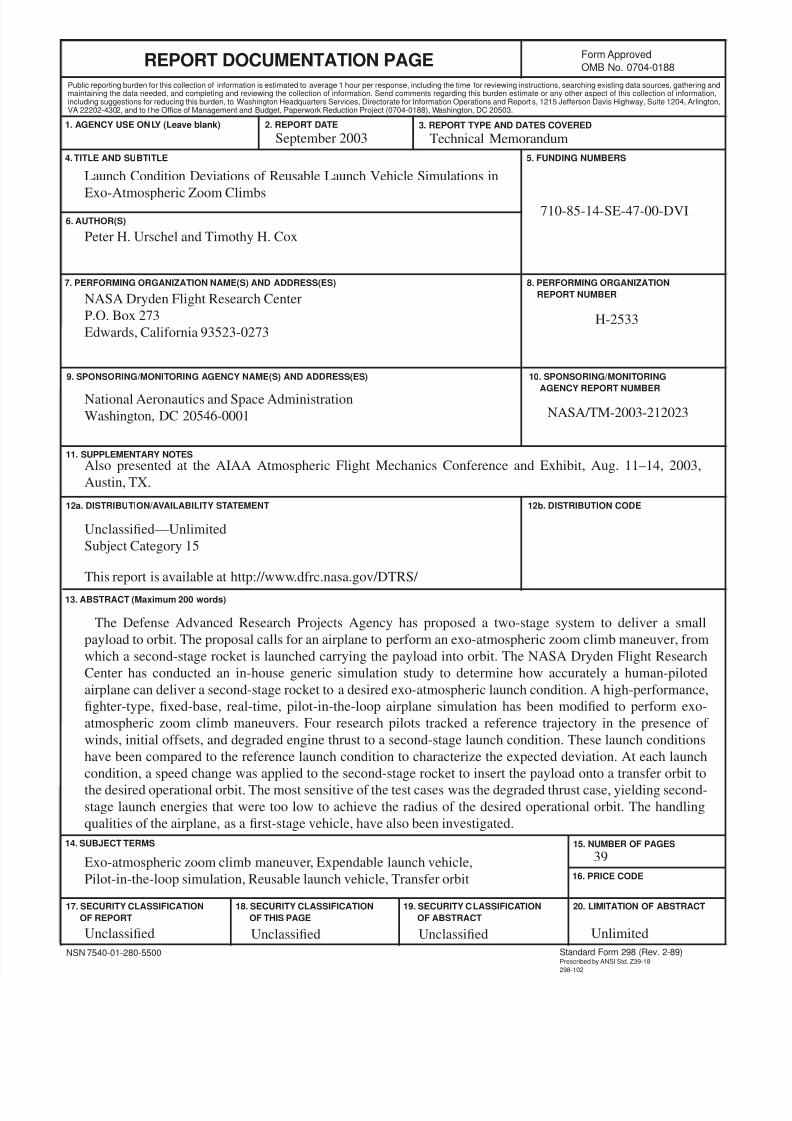
The Defense Advanced Research Projects Agency has proposed a two-stage system to deliver a smallpayload to orbit. The proposal calls for an airplane to perform an exo-atmospheric zoom climb maneuver,from which a second-stage rocket is launched carrying the payload into orbit. The NASA Dryden FlightResearch Center has conducted an in-house generic simulation study to determine how accurately ahuman-piloted airplane can deliver a second-stage rocket to a desired exo-atmospheric launch condition.A high-performance, fighter-type, fixed-base, real-time, pilot-in-the-loop airplane simulation has beenmodified to perform exo-atmospheric zoom climb maneuvers. Four research pilots tracked a referencetrajectory in the presence of winds, initial offsets, and degraded engine thrust to a second-stage launchcondition. These launch conditions have been compared to the reference launch condition to characterizethe expected deviation. At each launch condition, a speed change was applied to the second-stage rocketto insert the payload onto a transfer orbit to the desired operational orbit. The most sensitive of the testcases was the degraded thrust case, yielding second-stage launch energies that were too low to achievethe radius of the desired operational orbit. The handling qualities of the airplane, as a first-stage vehicle,have also been investigated.
NOMENCLATURE
Acronyms
CHR Cooper-Harper rating
DARPA Defense Advanced Research Projects Agency
ELV expendable launch vehicle
HUD head-up display
ILS instrument landing system
MIPCC mass injection pre-compressor cooling
RASCAL Responsive Access, Small Cargo, and Affordable Launch
RCS reaction control system
RLV reusable launch vehicle
VVS velocity vector symbol
Symbols
a
semimajor axis length of operational orbit, nmi
CAP
control anticipation parameter, g
-1
sec
-2
coefficient of yaw due to sideslip, per deg
d/dt time rate of change (first derivative with respect to time)
Cnβ
8/6/2019 Launch Conditions Deviations of Reusable Vehicle
http://slidepdf.com/reader/full/launch-conditions-deviations-of-reusable-vehicle 6/39
2
e eccentricity
g
gravitational acceleration
Η
altitude, ft
i
inclination of the operational orbit, deg
J
2
geopotential coefficient
Κ
ctrk
gain on crosstrack error
Κ
ctrkrt
gain on crosstrack rate
Κ
H
gain on altitude error
Κ
hor
gain on horizontal needle
Κ
vert
gain on vertical needle
Κα
gain on angle-of-attack error
Κθ
gain on pitch attitude error
Κφ
gain on bank angle error
Μ
Mach number
q
dynamic pressure, lb/ ft
2
R
lnch
geocentric radius of launch condition, nmi
R
op
geocentric radius of operational orbit, nmi
R
⊕
Earth’s equatorial radius, nmi
TC
azimuth of the launch condition in the rotating Earth reference frame (true course), deg
UT
universal time, sec
V
true airspeed, ft/sec
V
i
geocentric, inertial reference frame launch speed, nmi/sec
V
ix
horizontal component of geocentric, inertial speed, nmi/sec
V
iy
vertical component of geocentric, inertial speed, nmi/sec
V
op
geocentric speed required to be on circular operational orbit, nmi/sec
V
sound
speed of sound, ft/sec
V
T
geocentric transfer orbit speed at launch point (inertial frame), nmi/sec
α
angle of attack, deg
β
angle of sideslip, deg
γ
flightpath angle in rotating Earth reference frame, deg
8/6/2019 Launch Conditions Deviations of Reusable Vehicle
http://slidepdf.com/reader/full/launch-conditions-deviations-of-reusable-vehicle 7/39
3
γ
i
launch flightpath angle in nonrotating geocentric inertial frame, deg
γ
o
flighpath angle on operational orbit, deg
γ
op
flightpath angle on circular operational orbit, deg
∆
change in a parameter
∆
V
pc
geocentric speed change required to complete a plane change maneuver, nmi/sec
∆
V
tot
total geocentric speed change required to insert ELV onto transfer orbit and onto operational
orbit, nmi/sec
(
i.e., ∆
V
tot
=
∆
V
1
+ ∆
V
2
)
∆
V
1
speed change required to insert ELV onto transfer orbit from launch flight condition, nmi/sec
∆
V
2
speed change required to insert ELV onto operational orbit from transfer orbit, nmi/sec
ε
specific mechanical energy of the transfer orbit, nmi
2
/
sec
2
η
auxiliary angle, deg
θ
pitch attitude, deg
ι
longitude of launch condition, deg
λ
gc
geocentric latitude of the launch condition, deg
µ
⊕
gravitational parameter of Earth
τ
GST
Greenwich sidereal time, sec
τ
GST0
Greenwich sidereal time at zero hours on launch day, sec
φ
bank angle, deg
χ specific angular momentum of the transfer orbit, nmi
2
/ sec
ψ
inertial launch azimuth measured from true north, deg
ω
⊕
Earth’s rotational rate, rad/sec
Ω
longitude of the ascending node, deg
INTRODUCTION
Reliable, flexible, and low-cost access to space is becoming increasingly important for bothcommercial and military programs. Although many dedicated, flight-proven launch vehicles are currentlyavailable, a gap exists in the dedicated launch capability for payloads less than 220 lb. Current trendsindicate that payload size is decreasing and potential uses of low Earth orbit satellite constellations arebeing evaluated, thereby increasing the need for dedicated launch capability for payloads less than 220 lb.
1
8/6/2019 Launch Conditions Deviations of Reusable Vehicle
http://slidepdf.com/reader/full/launch-conditions-deviations-of-reusable-vehicle 8/39
4
Most launch vehicle systems are optimized for payloads much larger than 220 lb. They require largeteams of highly trained personnel, dedicated launch ranges, and, with the exception of Sea Launch (SeaLaunch Company, LLC, Long Beach, California) and the air-launched Pegasus ® (Orbital SciencesCorporation, Dulles, Virginia), large and complex land-based launch facilities. They also have lengthyprelaunch payload processing and launch vehicle integration flows, and have launch windows that arelimited by the fixed geographic location of the launch site on the surface of the Earth (with the exception
of Pegasus). Additionally, because payloads less than 220 lb must be launched into orbit by means of piggybacking onto larger payloads available on current launch vehicles, the orbit injection requirementsof the larger payload generally take precedence over those of the smaller payload, thereby restricting oreliminating access to the desired operational orbit.
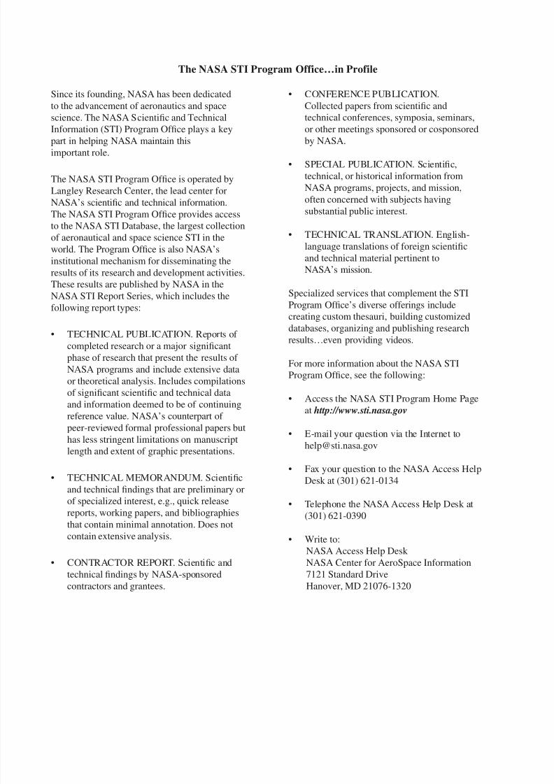
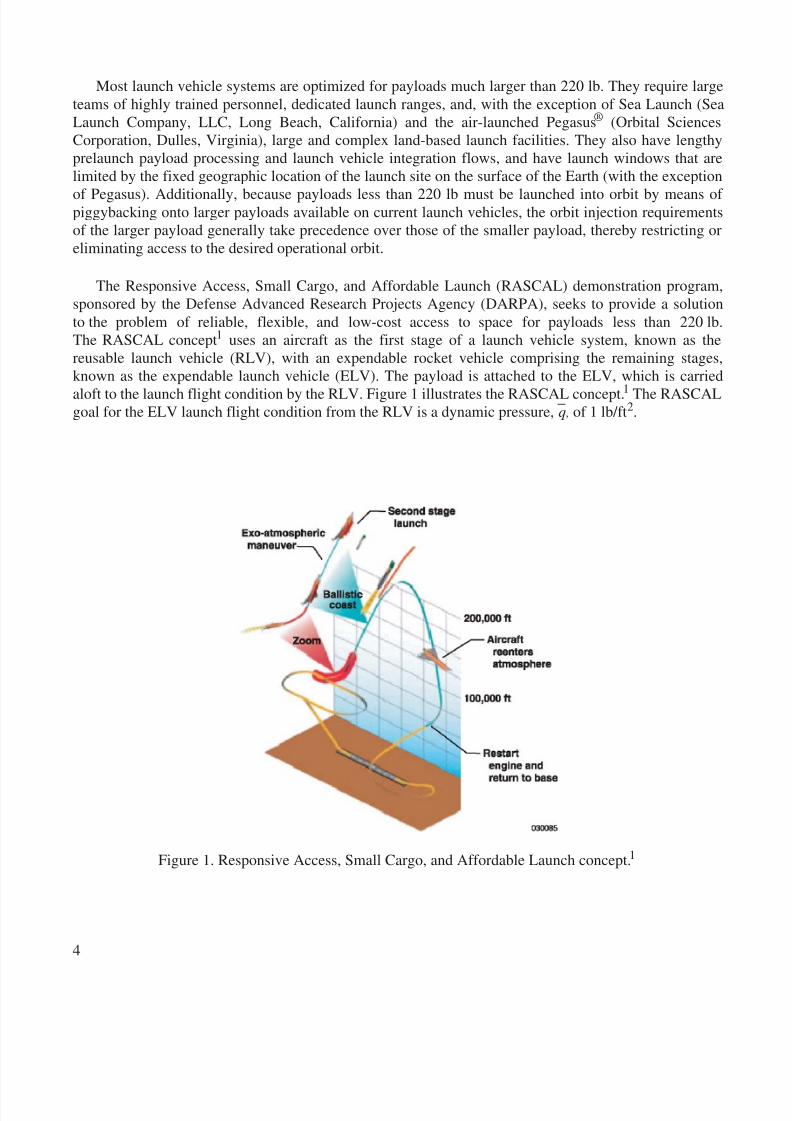
The Responsive Access, Small Cargo, and Affordable Launch (RASCAL) demonstration program,sponsored by the Defense Advanced Research Projects Agency (DARPA), seeks to provide a solutionto the problem of reliable, flexible, and low-cost access to space for payloads less than 220 lb.The RASCAL concept 1 uses an aircraft as the first stage of a launch vehicle system, known as thereusable launch vehicle (RLV), with an expendable rocket vehicle comprising the remaining stages,known as the expendable launch vehicle (ELV). The payload is attached to the ELV, which is carriedaloft to the launch flight condition by the RLV. Figure 1 illustrates the RASCAL concept. 1 The RASCALgoal for the ELV launch flight condition from the RLV is a dynamic pressure, q , of 1 lb/ft 2.
Figure 1. Responsive Access, Small Cargo, and Affordable Launch concept. 1
8/6/2019 Launch Conditions Deviations of Reusable Vehicle
http://slidepdf.com/reader/full/launch-conditions-deviations-of-reusable-vehicle 9/39
5
The following is a direct quote from reference 1:
Aircraft operations are a good example of operations that are exible and adaptable towards evolving and emergingmissions. Aircraft operations are also affordable, in part, because an extensive and highly developed infrastructure andtechnology base exist. The development of a successful RASCAL system will use aircraft operations as a stronginuence in its concept of operations and will take as much advantage as possible of existing aircraft infrastructure andtechnology. 1
Based on this assessment, DARPA has proposed an extension of military aircraft operations for the RLVto meet the following objectives:
1. Demonstrate mission turnaround time within a 24-hour period after payload arrival (at RLV sortiepoint of origin)
2. Deliver a 165-lb payload into a 270-nmi (altitude) sun synchronous orbit
3. Demonstrate, through a credible cost estimating model, that recurring launch costs can convergeon the goal of $750,000 per launch of a 165-lb payload for the RASCAL operating system (notincluding the cost of the satellite payload)
4. Validate the ability to operate from an 8200-ft runway with minimal peculiar support equipment,independent of test ranges for telemetry and tracking support
5. Demonstrate mission scramble capability within 1 hour of notication, after ELV integration
6. Demonstrate the ability to loiter and adjust the ightpath to accommodate dynamic missionplanning
Additionally, the RASCAL concept requires that the RLV achieve the launch flight condition bymeans of conventional airbreathing jet engines, without the use of rocket engines. For the RLV to achievethe desired ELV launch flight condition without the use of rocket engines, the RASCAL concept calls forthe development of mass injection pre-compressor cooling (MIPCC) systems for use with conventional
jet engines. The MIPCC systems provide thrust augmentation and extended engine operation into flightregimes beyond the operating envelope of conventional airbreathing engines.
Few research efforts have employed a concept similar to that of the RASCAL program. Of allprevious research programs, the X-15 and NF-104 programs 2 are the most similar (conceptually) toRASCAL. The X-15 aircraft reached altitudes exceeding 350,000 ft and apogee speeds of approximately4500 ft/sec, 3 necessitating piloting techniques and guidance and control strategies 4,5 similar to thoserequired by RASCAL. Significant differences exist, however, between the RASCAL requirements andthose upon which the X-15 aircraft was designed, built, and operated. One of the main differences is thatthe RASCAL RLV must carry an ELV to a tightly constrained launch flight condition, at which time theELV separates from the RLV and ignites its own rocket engine(s) for insertion of the satellite payloadinto orbit.
The NASA Dryden Flight Research Center (Edwards, California) has participated in the RASCALphase I program and performed a generic RASCAL simulation study. The main objectives of the studywere to quantify deviations expected in the ELV launch condition and examine how these deviationspropagate through the subsequent ELV transfer orbit. Consistent with the RASCAL concept, a real-time,fixed-base, pilot-in-the-loop simulation of a fighter aircraft, complete with pilot controls and externalvisual imagery, was modified and used as a generic RLV. A reference zoom climb maneuver, consistentwith DARPA objectives, was generated ad hoc and implemented into the simulation to drive guidance
8/6/2019 Launch Conditions Deviations of Reusable Vehicle
http://slidepdf.com/reader/full/launch-conditions-deviations-of-reusable-vehicle 10/39
6
displays. Four NASA Dryden research pilots flew the simulation and tracked the reference trajectory todocument the ELV launch condition deviations from the reference launch condition. In addition to thenominal case, the pilots tracked the reference trajectory in the presence of winds, with reduced thrust, andwith initial condition offsets at the start of the maneuver. Handling qualities and guidance displayconcepts, which are significant factors in the pilot’s ability to track the reference trajectory, have beendocumented and discussed. Although an autopilot probably would be used to fly this type of maneuver,
the use of a human pilot-in-the-loop simulation has facilitated insight into the design of the maneuver,facilitated the identification of problems in the dynamics during the maneuver, and utilized the humanpilot’s inherent adaptability and insight to more efficiently develop the guidance concept. Under theassumption that an autopilot can track more precisely than a human pilot can, this process should result ina worst-case set of ELV launch deviations. A conceptual ELV transfer orbit was developed, and thelaunch conditions from each trajectory have been applied to examine the effects on the final ELV orbitalstate. Correlations between the ELV launch condition and the final ELV orbital states have been made,and the most sensitive launch condition parameters have been identified. The objective of these data is toprovide insight to those who must design the size of the ELV to account for ELV launch and transferorbit errors.
TEST SETUP
This section discusses the setup for the test simulation. The aircraft, simulation facility, referenceRLV trajectory, pilot guidance and display, wind profile variations, and ELV transfer orbit are describedin detail.
Aircraft
A fighter-type aircraft was chosen for use as the RLV in this study. This aircraft, with the addition of MIPCC augmentation, best represents the capabilities required by the RASCAL RLV concept. It is ahigh-performance, twin-engine, tactical jet fighter airplane with a maximum design Mach number of 2.5without MIPCC. It possesses the airframe geometric configuration, area, and payload capability requiredto carry an ELV-class payload. Another factor for choosing this aircraft is the availability of a real-time,pilot-in-the-loop simulation capability.
The aircraft is controlled by stabilators, which are symmetrically and differentially deflected,ailerons, and rudders. A control augmentation system drives the surfaces, using rates, accelerations, andangle-of-attack feedbacks. With the control augmentation system active, the control system providesnormal acceleration command in the pitch axis and roll rate in the lateral axis.
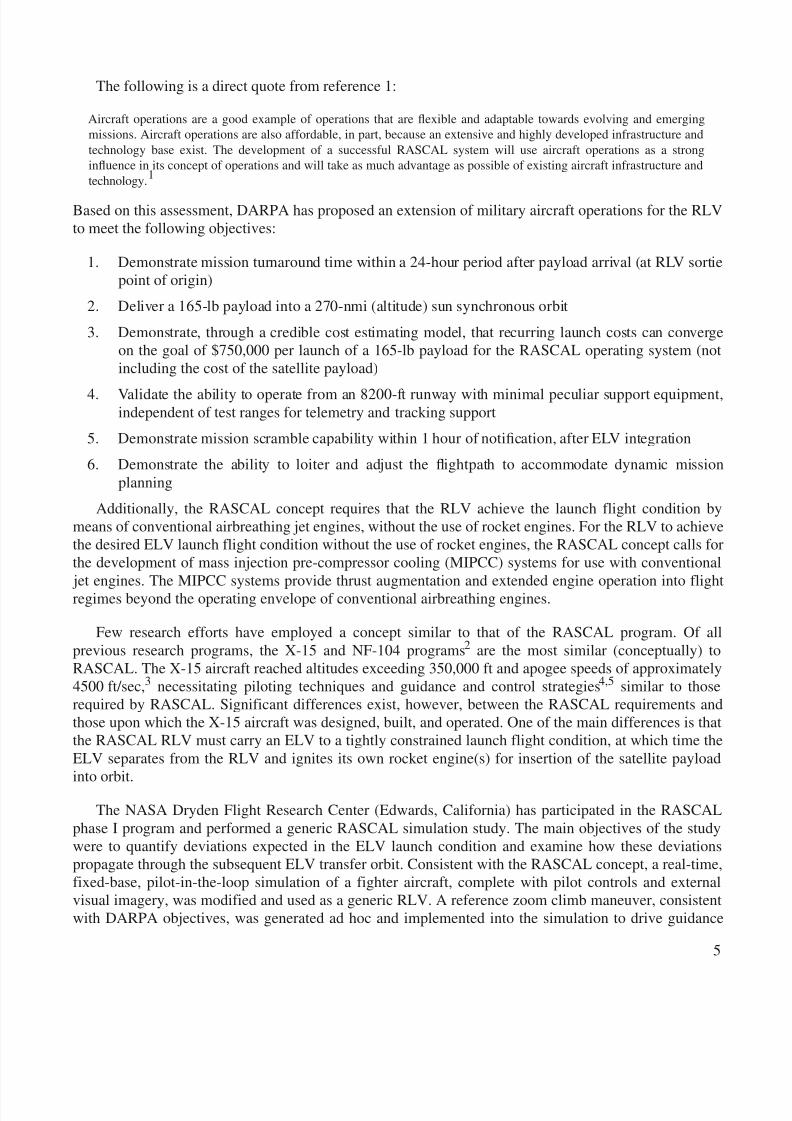
Simulation FacilityThe NASA Dryden simulation facility (fig. 2) is a fixed-base, real-time, pilot-in-the-loop,
six-degree-of- freedom simulation with a standard stick and rudder pedal for pilot controls, head-updisplay (HUD) and cockpit flight instruments, and external real-time visual imagery. Oblate Earthnonlinear equations of motion are used. High-fidelity propulsion and aerodynamic models were alsoimplemented and considered valid to Mach 2.5 and altitudes of 70,000 ft. For the RASCAL study,modifications to the simulation included the implementation of a reaction control system (RCS);
8/6/2019 Launch Conditions Deviations of Reusable Vehicle
http://slidepdf.com/reader/full/launch-conditions-deviations-of-reusable-vehicle 11/39
7
an extension of the aerodynamic model in Mach number and altitude; the implementation of a simpleMIPCC thrust augmentation model; the development of a guidance algorithm that generates commandsto instrument landing system (ILS) type needles; and fine-tuning of the control system. Thesemodifications, discussed in detail in the remainder of this section, were considered reasonable estimatesbased on the conceptual nature of the study.
RCS Design and Flight Control System Modification
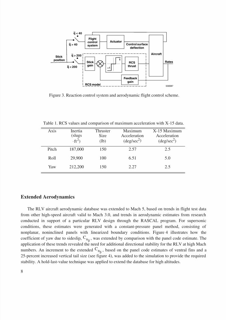
The RCS has been designed to be similar to the proportional, rate command system of the X-15aircraft. 6,7 Dead bands were used on the error signals and stick position but were not fine-tuned for fuelusage or to minimize rocket fire time. A set of pitch and yaw thrusters were modeled on the nose and thetail of the aircraft, and a set of roll axis thrusters were modeled on each wingtip. As shown in figure 3, thesame stick and rudder pedals used for atmospheric flight were used to activate the RCS inexo-atmospheric flight. For dynamic pressure greater than 200 lb/ft 2, pure aerodynamic control was used.For dynamic pressure less than 200 lb/ft 2, the RCS switched on to supplement the aerodynamic control.For dynamic pressure less than 40 lb/ft 2, the control surfaces were frozen and control was exclusivelymaintained by the RCS. These dynamic pressure values were not optimal but were chosen to avoidpotential handling qualities problems during the zoom climb. Table 1 lists the inertias and thruster sizeand shows that the resultant maximum acceleration compares well to that of the X-15 design.
Initial investigations revealed that the aircraft exhibited a wallowing characteristic as it entered theupper end of the atmosphere during the zoom climb. This wallowing characteristic was traced to areduction in damping during the climb in all three axes. During this portion of the flight, the dimensionaldamping derivatives, a function of q / V , decreased by a factor of 10 because of a rapid decrease indynamic pressure. To provide increased aerodynamic damping, rate feedback gains in the control systemwere ramped from the nominal gain at the start of the pullup to a factor of 10 according to dynamicpressure variation. Stability was validated through the pilot-in-the-loop simulation, and robustness of thecontrol laws was not analyzed.
Figure 2. The NASA Dryden simulation facility.
8/6/2019 Launch Conditions Deviations of Reusable Vehicle
http://slidepdf.com/reader/full/launch-conditions-deviations-of-reusable-vehicle 12/39
8
Extended Aerodynamics
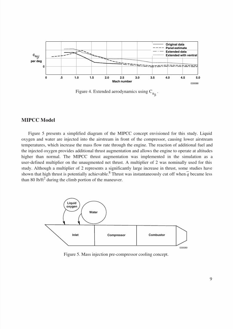
The RLV aircraft aerodynamic database was extended to Mach 5, based on trends in flight test datafrom other high-speed aircraft valid to Mach 3.0, and trends in aerodynamic estimates from researchconducted in support of a particular RLV design through the RASCAL program. For supersonicconditions, these estimates were generated with a constant-pressure panel method, consisting of nonplanar, noninclined panels with linearized boundary conditions. Figure 4 illustrates how thecoefficient of yaw due to sideslip, , was extended by comparison with the panel code estimate. Theapplication of these trends revealed the need for additional directional stability for the RLV at high Machnumbers. An increment to the extended , based on the panel code estimates of ventral fins and a25-percent increased vertical tail size (see figure 4), was added to the simulation to provide the requiredstability. A hold-last-value technique was applied to extend the database for high altitudes.
Table 1. RCS values and comparison of maximum acceleration with X-15 data.
Axis Inertia(slugs⋅ft 2)
ThrusterSize(lb)
MaximumAcceleration
(deg/sec 2)
X-15 MaximumAcceleration
(deg/sec 2)
Pitch 187,000 150 2.57 2.5
Roll 29,900 100 6.51 5.0
Yaw 212,200 150 2.27 2.5
Rates
Stick position
q > 200
q < 200
q > 40
q < 40
Flightcontrolsystem
Actuator
Aircraft
Control surfacedeflection
–1
1
RCS model
–
–
–
–Stick gain
RCSthrust
Feedback gain
030087
Figure 3. Reaction control system and aerodynamic flight control scheme.
Cnβ
Cnβ
8/6/2019 Launch Conditions Deviations of Reusable Vehicle
http://slidepdf.com/reader/full/launch-conditions-deviations-of-reusable-vehicle 13/39
9
MIPCC Model
Figure 5 presents a simplified diagram of the MIPCC concept envisioned for this study. Liquidoxygen and water are injected into the airstream in front of the compressor, causing lower airstreamtemperatures, which increase the mass flow rate through the engine. The reaction of additional fuel andthe injected oxygen provides additional thrust augmentation and allows the engine to operate at altitudeshigher than normal. The MIPCC thrust augmentation was implemented in the simulation as auser-defined multiplier on the unaugmented net thrust. A multiplier of 2 was nominally used for thisstudy. Although a multiplier of 2 represents a significantly large increase in thrust, some studies haveshown that high thrust is potentially achievable. 8 Thrust was instantaneously cut off when q became lessthan 80 lb/ft 2 during the climb portion of the maneuver.
0
0 1.0 1.5.5 2.0 2.5Mach number
3.0 3.5 4.0 4.5 5.0
030088
Cnβ
,
per deg
Original dataPanel estimateExtended dataExtended with ventral
Figure 4. Extended aerodynamics using .Cnβ
Compressor Combustor
030089
Inlet
Liquidoxygen
Water
Figure 5. Mass injection pre-compressor cooling concept.
8/6/2019 Launch Conditions Deviations of Reusable Vehicle
http://slidepdf.com/reader/full/launch-conditions-deviations-of-reusable-vehicle 14/39
10
Control Power Modification
Initial trajectory investigations indicated the control power of the original RLV configuration wasmarginally acceptable, and the stick occasionally was reaching the aft limit. A 20-percent increase in the
deflection of the stabilators and a 1-in. increase in aft stick deflection corrected this problem. A slightreduction in the force gradient of the stick allowed stick force per g to remain the same as the originalconfiguration.
Reference RLV Trajectory
The design operational orbit was assumed to be a geocentric, circular, 270-nmi altitude, sun
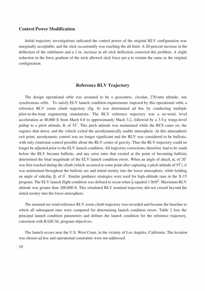
synchronous orbit. To satisfy ELV launch condition requirements imposed by this operational orbit, areference RLV zoom climb trajectory (fig. 6) was determined ad hoc by conducting multiplepilot-in-the-loop engineering simulations. The RLV reference trajectory was a no-wind, levelacceleration at 40,000 ft from Mach 0.8 to approximately Mach 3.2, followed by a 3.5- g wings-levelpullup to a pitch attitude, θ, of 55 °. This pitch attitude was maintained while the RCS came on, theengines shut down, and the vehicle exited the aerodynamically usable atmosphere. At this atmosphericexit point, aerodynamic control was no longer significant and the RLV was considered to be ballistic,with only rotational control possible about the RLV center of gravity. Thus the RLV trajectory could nolonger be adjusted prior to the ELV launch condition. All trajectory corrections, therefore, had to be made
before the RLV became ballistic, and any error rates that existed at the point of becoming ballisticdetermined the final magnitude of the ELV launch condition errors. When an angle of attack, α , of 20 °
was first reached during the climb (which occurred at some point after capturing a pitch attitude of 55 °), itwas maintained throughout the ballistic arc and initial reentry into the lower atmosphere, while holdingan angle of sideslip, β, of 0 °. Similar guidance strategies were used for high-altitude runs in the X-15program. The ELV launch flight condition was defined to occur when q equaled 1 lb/ft 2. Maximum RLValtitude was greater than 200,000 ft. This simulated RLV nominal trajectory did not extend beyond theinitial reentry into the lower atmosphere.
The nominal no-wind reference RLV zoom climb trajectory was recorded and became the baseline towhich all subsequent runs were compared for determining launch condition errors. Table 2 lists theprincipal launch condition parameters and defines the launch condition for the reference trajectory,consistent with RASCAL program objectives.
The launch occurs near the U.S. West Coast, in the vicinity of Los Angeles, California. The locationwas chosen ad hoc and operational constraints were not addressed.
8/6/2019 Launch Conditions Deviations of Reusable Vehicle
http://slidepdf.com/reader/full/launch-conditions-deviations-of-reusable-vehicle 15/39
11
Figure 6. Reference trajectory.
Table 2. Launch condition for the reference trajectory.
Parameter Value
Altitude, H 202,760 ft
Mach number, Μ 2.00Time from start of level acceleration 181.9 secFlightpath angle, γ 18.2°
Inertial launch, azimuth, Ψ 188.8 °
Geocentric latitude, λgc 34.0°
Longitude, ι –118.9 °
Altitude,ft
2
x 10 5
Mach
Angulardisplacement,
deg
Flightpathangle,
deg
Time, sec
q,lb/ft 2
θα
Launch (q = 1 lb/ft 2)
RCS on
Level accelerationNonballistic
pullup Ballistic
3.5 g pull
1
0
4
3
2
1
60
40
20
0
604020
0–20
–40
3000
2000
1000
50
–
–
Engineshutdown
Constant θ
Constant α
0 100 150 200
030090
250
8/6/2019 Launch Conditions Deviations of Reusable Vehicle
http://slidepdf.com/reader/full/launch-conditions-deviations-of-reusable-vehicle 16/39
12
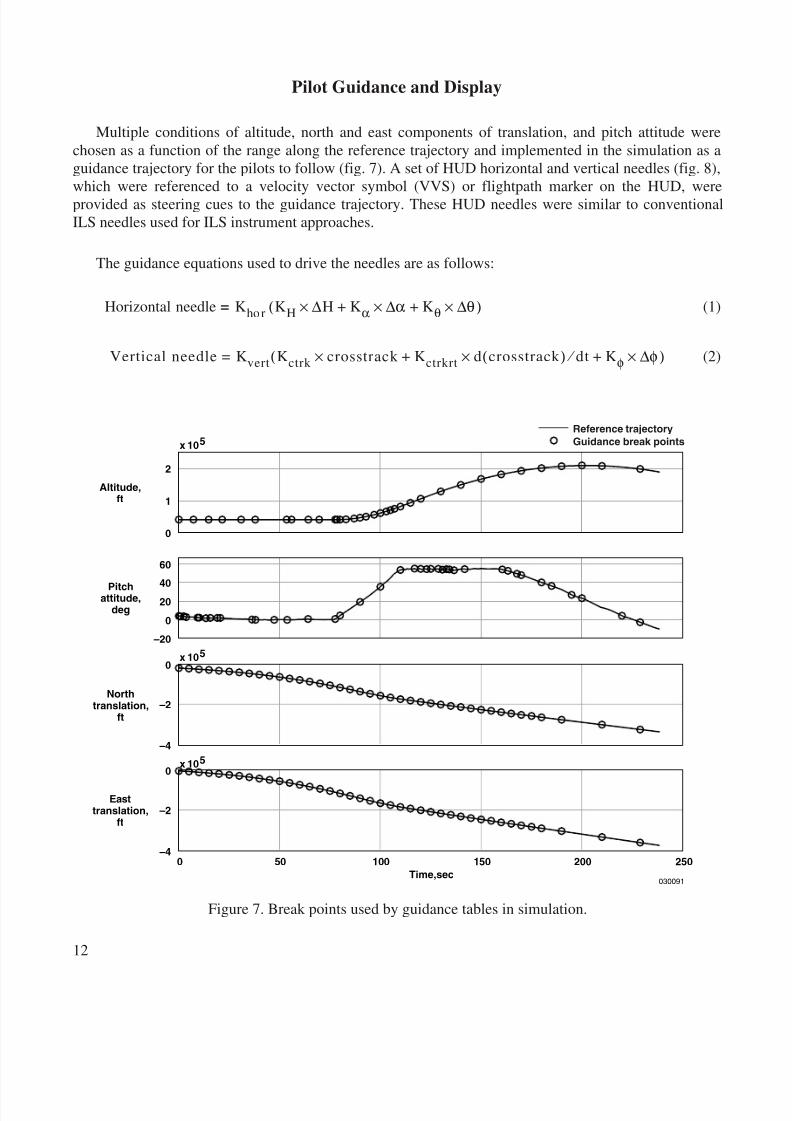
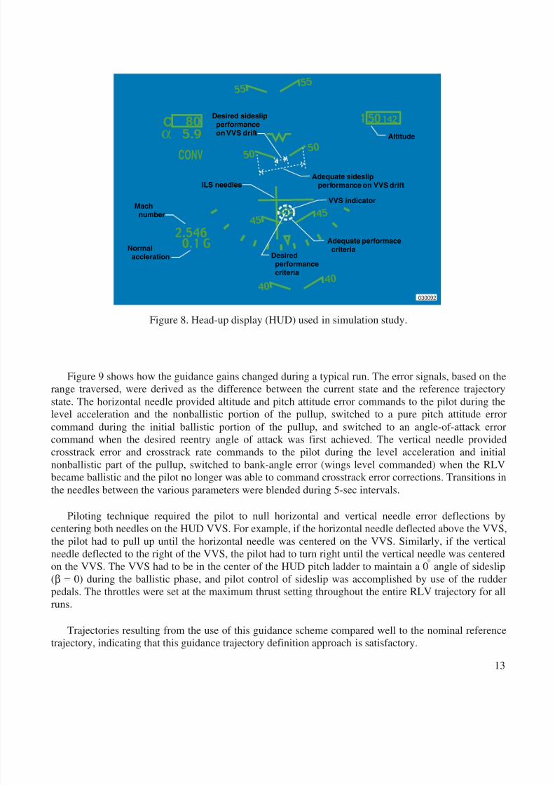
Pilot Guidance and Display
Multiple conditions of altitude, north and east components of translation, and pitch attitude werechosen as a function of the range along the reference trajectory and implemented in the simulation as aguidance trajectory for the pilots to follow (fig. 7). A set of HUD horizontal and vertical needles (fig. 8),which were referenced to a velocity vector symbol (VVS) or flightpath marker on the HUD, wereprovided as steering cues to the guidance trajectory. These HUD needles were similar to conventionalILS needles used for ILS instrument approaches.
The guidance equations used to drive the needles are as follows:
(1)
(2)
Horizontal needle = Khor KH ∆× H Kα ∆α Kθ ∆θ×+×+( )
Vertical needle K vert= Kctrk crosstrack K ctrkrt d×+× crosstrack ( ) dt K φ ∆φ×+ ⁄ ( )
0
Altitude,ft
Pitchattitude,deg
Northtranslation,
ft
Easttranslation,
ft
Time,sec
Reference trajectoryGuidance break pointsx 10 5
2
50 100 150 200 250
030091
1
0
60
40
20
0
–20
0
–2
–4
0
–2
–4
x 10 5
x 10 5
Figure 7. Break points used by guidance tables in simulation.
8/6/2019 Launch Conditions Deviations of Reusable Vehicle
http://slidepdf.com/reader/full/launch-conditions-deviations-of-reusable-vehicle 17/39
13
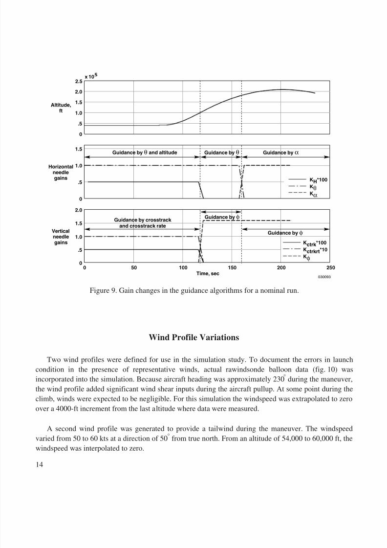
Figure 9 shows how the guidance gains changed during a typical run. The error signals, based on therange traversed, were derived as the difference between the current state and the reference trajectorystate. The horizontal needle provided altitude and pitch attitude error commands to the pilot during thelevel acceleration and the nonballistic portion of the pullup, switched to a pure pitch attitude errorcommand during the initial ballistic portion of the pullup, and switched to an angle-of-attack errorcommand when the desired reentry angle of attack was first achieved. The vertical needle providedcrosstrack error and crosstrack rate commands to the pilot during the level acceleration and initialnonballistic part of the pullup, switched to bank-angle error (wings level commanded) when the RLVbecame ballistic and the pilot no longer was able to command crosstrack error corrections. Transitions inthe needles between the various parameters were blended during 5-sec intervals.
Piloting technique required the pilot to null horizontal and vertical needle error deflections bycentering both needles on the HUD VVS. For example, if the horizontal needle deflected above the VVS,the pilot had to pull up until the horizontal needle was centered on the VVS. Similarly, if the verticalneedle deflected to the right of the VVS, the pilot had to turn right until the vertical needle was centeredon the VVS. The VVS had to be in the center of the HUD pitch ladder to maintain a 0
°
angle of sideslip(
β
=
0) during the ballistic phase, and pilot control of sideslip was accomplished by use of the rudderpedals. The throttles were set at the maximum thrust setting throughout the entire RLV trajectory for allruns.
Trajectories resulting from the use of this guidance scheme compared well to the nominal referencetrajectory, indicating that this guidance trajectory definition approach is satisfactory.
C
5 0
4 54 5
5 0
80 501 142
5.9
2.5460.1 G
αCONV
4 04 0
5 55 5
Machnumber
ILS needles
VVS indicator
Altitude
Desiredperformance
criteria
Adequate performacecriteriaNormal
accleration
Desired sideslipperformanceon VVS drift
Adequate sideslipperformance on VVS drift
030092
Figure 8. Head-up display (HUD) used in simulation study.
8/6/2019 Launch Conditions Deviations of Reusable Vehicle
http://slidepdf.com/reader/full/launch-conditions-deviations-of-reusable-vehicle 18/39
14
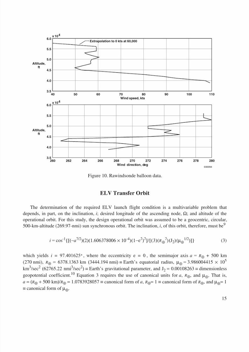
Wind Profile Variations
Two wind profiles were defined for use in the simulation study. To document the errors in launchcondition in the presence of representative winds, actual rawindsonde balloon data (fig. 10) wasincorporated into the simulation. Because aircraft heading was approximately 230
°
during the maneuver,the wind profile added significant wind shear inputs during the aircraft pullup. At some point during theclimb, winds were expected to be negligible. For this simulation the windspeed was extrapolated to zeroover a 4000-ft increment from the last altitude where data were measured.
A second wind profile was generated to provide a tailwind during the maneuver. The windspeedvaried from 50 to 60 kts at a direction of 50
°
from true north. From an altitude of 54,000 to 60,000 ft, thewindspeed was interpolated to zero.
Altitude,ft
Horizontalneedlegains
Verticalneedlegains
Time, sec
Guidance by θ and altitude
Guidance by crosstrack and crosstrack rate
Guidance by θ Guidance by α
Guidance by φ
Guidance by φ
KH*100KθKα
Kctrk *100Kctrkrt *10Kφ
x 10 52.5
2.0
1.5
1.0
.5
0
1.5
1.0
.5
0
2.0
1.5
1.0
.5
00 50 100 150 200 250
030093
Figure 9. Gain changes in the guidance algorithms for a nominal run.
8/6/2019 Launch Conditions Deviations of Reusable Vehicle
http://slidepdf.com/reader/full/launch-conditions-deviations-of-reusable-vehicle 19/39
15
ELV Transfer Orbit
The determination of the required ELV launch flight condition is a multivariable problem thatdepends, in part, on the inclination, i
; desired longitude of the ascending node, Ω
; and altitude of theoperational orbit. For this study, the design operational orbit was assumed to be a geocentric, circular,500-km-altitude (269.97-nmi) sun synchronous orbit. The inclination, i
, of this orbit, therefore, must be
9
i
= cos
-1
[(−
a
7/2
)(2)(1.606378006 × 10
-4
)(1−
e
2
)
2
]/[(3)(
R
⊕
2
)(
J
2
)(µ
⊕
1/2
)]
(3)
which yields , where the eccentricity , the semimajor axis a
=
R
⊕
+ 500 km(270 nmi), R
⊕ = 6378.1363 km (
3444.194 nmi
)
≡ Earth’s equatorial radius, µ
⊕
=
3.986004415 ×
10
5
km
3
/
sec
2
(
62765.22 nmi
3
/sec
2
)
≡
Earth’s gravitational parameter, and J
2
=
0.00108263
≡
dimensionlessgeopotential coefficient.
10
Equation 3 requires the use of canonical units for
a
, R
⊕
, and µ
⊕
. That is,
a
= (
R
⊕
+
500 km
)/
R
⊕
= 1.0783928057 ≡
canonical form of a
, R
⊕
= 1
≡ canonical form of R
⊕
, and µ
⊕
= 1≡ canonical form of µ
⊕.
Altitude,ft
x 10 46.0
Wind speed, kts
5.5
5.0
4.5
Altitude,ft
4.0
3.550
x 10 46.0
5.5
5.0
4.5
4.0
3.5262
40 60 70 80 90 100 110
260 264 266 268 270Wind direction, deg
272 274 276 278
030094
280
Extrapolation to 0 kts at 60,000
Figure 10. Rawindsonde balloon data.
i 97.401625 °= e 0=
8/6/2019 Launch Conditions Deviations of Reusable Vehicle
http://slidepdf.com/reader/full/launch-conditions-deviations-of-reusable-vehicle 20/39
16
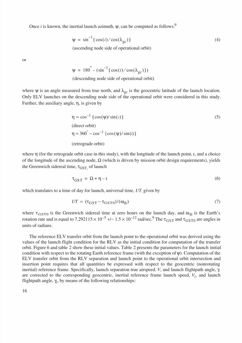
Once i is known, the inertial launch azimuth, ψ, can be computed as follows: 9
(4)
or
where ψ is an angle measured from true north, and λgc is the geocentric latitude of the launch location.Only ELV launches on the descending node side of the operational orbit were considered in this study.Further, the auxiliary angle, η, is given by
η = cos –1 cos (ψ)/ sin ( i) (5)
(direct orbit)
η = 360° − cos –1 cos (ψ)/ sin (i)
(retrograde orbit)
where η (for the retrograde orbit case in this study), with the longitude of the launch point, ι, and a choiceof the longitude of the ascending node, Ω (which is driven by mission orbit design requirements), yieldsthe Greenwich sidereal time, τGST, of launch
(6)
which translates to a time of day for launch, universal time, UT , given by
UT = (τ GST − τ GST0 )/(ω⊕) (7)
where τ GST0 is the Greenwich sidereal time at zero hours on the launch day, and ω⊕ is the Earth’srotation rate and is equal to 7.292115 × 10 –5 +/− 1.5 × 10 –12 rad/sec. 9 The τ GST and τ GST0 are angles inunits of radians.
The reference ELV transfer orbit from the launch point to the operational orbit was derived using thevalues of the launch flight condition for the RLV as the initial condition for computation of the transferorbit. Figure 6 and table 2 show these initial values. Table 2 presents the parameters for the launch initialcondition with respect to the rotating Earth reference frame (with the exception of ψ ). Computation of theELV transfer orbit from the RLV separation and launch point to the operational orbit intersection andinsertion point requires that all quantities be expressed with respect to the geocentric (nonrotatinginertial) reference frame. Specifically, launch separation true airspeed, V , and launch flightpath angle, γ ,are corrected to the corresponding geocentric, inertial reference frame launch speed, V i, and launchflightpath angle, γ i, by means of the following relationships:
ψ sin1–
i( ) λ gc( )cos ⁄ cos
(ascending node side of operational orbit)
=
ψ 180 ° sin1–
i( ) λ gc( )cos ⁄ cos ( )–
descending node side of operational orbit( )
=
τGST Ω η ι–+=
8/6/2019 Launch Conditions Deviations of Reusable Vehicle
http://slidepdf.com/reader/full/launch-conditions-deviations-of-reusable-vehicle 21/39
17
V ix2 = (V 2) (cos2(γ)) + (ω⊕
2)( R lnch2)(cos 2(λgc )) − 2V ω⊕ Rlnch cos (γ) cos (λgc) cos (270° − TC ) (8)
where Rlnch ≡ geocentric radius of RLV at launch, TC ≡ launch azimuth in the rotating Earth referenceframe (RLV true course at launch), and V ix ≡ horizontal component of geocentric, inertial speed.Continuing,
(9)
where V iy is the vertical component of geocentric, inertial speed. Therefore,
(10)
and
(11)
which applies for a no-wind condition at the launch point in a standard atmosphere. All cases were set upso that the launch point flight condition occurred with zero wind (no winds were inserted into thesimulation above 60,000 ft). The launch separation true airspeed, V , is obtained from the relationshipM = V / V sound , where V sound ≡ the speed of sound at the launch flight condition in a standard atmosphere.
The quantities of launch condition V i and γ i, computed in equations 10 and 11, respectively, wereused with the other launch condition parameters to compute a transfer orbit using standard two-body
astrodynamic analysis techniques. A geocentric speed of V T = 6 km/sec (3.239 nmi/sec), required to beon the transfer orbit at the launch point, was iteratively selected, and the ELV was assumed to have thelaunch condition values of V i, γ i, and ψ at separation from the RLV. An impulsive (zero time) rocketengine burn was assumed to have occurred at the launch point. The burn provided the ∆V 1 = V T −V irequired to insert the ELV into the transfer orbit at the launch point, with a flightpath angle of γ i, speed of V T, and launch azimuth of ψ . The specific mechanical energy of the ELV transfer orbit, ε, is given by
ε = (V T2 /2 ) − (µ
⊕/ R lnch ) (12)
and the specific angular momentum of the ELV transfer orbit, χ , is given by
(13)
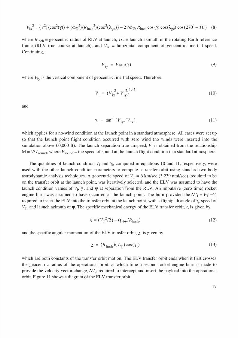
which are both constants of the transfer orbit motion. The ELV transfer orbit ends when it first crossesthe geocentric radius of the operational orbit, at which time a second rocket engine burn is made toprovide the velocity vector change, ∆V 2 , required to intercept and insert the payload into the operationalorbit. Figure 11 shows a diagram of the ELV transfer orbit.
V iy V γ ( )sin=
V i V ix2
V iy2
+( )1 2 ⁄
=
γ i tan 1– V iy V ix ⁄ ( )=
χ R chln( ) V T( ) γ i( )cos=
8/6/2019 Launch Conditions Deviations of Reusable Vehicle
http://slidepdf.com/reader/full/launch-conditions-deviations-of-reusable-vehicle 22/39
18
As previously stated, to compute the transfer orbit parameters, standard two-body astrodynamicanalysis techniques with impulsive velocity vector changes were used with the forementioned equations.To accomplish the ELV transfer to the operational orbit, the nominal transfer orbit was computed usingthe forementioned algorithms with the nominal RLV launch flight condition parameters as inputs. Anyvariations from the nominal values in the RLV launch flight condition parameters propagate through thesubsequent ELV transfer orbit, causing errors with respect to the nominal transfer orbit.
TEST METHOD
Four research pilots flew the following five test cases:
1. Nominal case
2. Initial offset case of 0.5-mile crosstrack and 500-ft altitude (inserted at the beginning of levelacceleration)
3. Tailwind case
4. Actual wind prole case with wind shear5. Thrust multiplier case of –3 percent to the unaugmented engine (approximating the effect of a
nonstandard hot day on a high-performance jet engine)
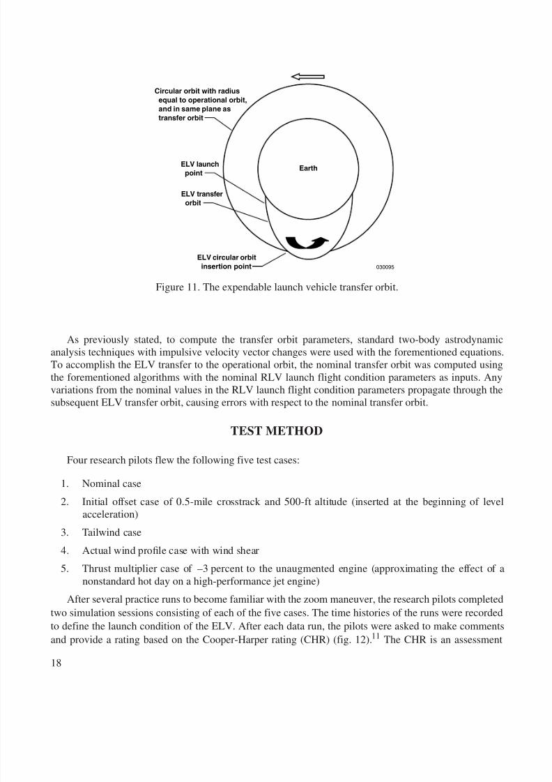
After several practice runs to become familiar with the zoom maneuver, the research pilots completedtwo simulation sessions consisting of each of the five cases. The time histories of the runs were recordedto define the launch condition of the ELV. After each data run, the pilots were asked to make commentsand provide a rating based on the Cooper-Harper rating (CHR) (fig. 12). 11 The CHR is an assessment
Circular orbit with radiusequal to operational orbit,and in same plane astransfer orbit
ELV launchpoint
ELV transferorbit
ELV circular orbitinsertion point
Earth
030095
Figure 11. The expendable launch vehicle transfer orbit.
8/6/2019 Launch Conditions Deviations of Reusable Vehicle
http://slidepdf.com/reader/full/launch-conditions-deviations-of-reusable-vehicle 23/39
19
tool for evaluating the ease and precision with which a pilot performs a defined task. The scale requiresthat a desired and adequate level of task performance be defined. The pilot performs the tasks and thenworks through the decision tree (fig. 12). A CHR is identified based on the level of performance achievedand the degree of difficulty in achieving it. Many of the handling qualities criteria defined in theMIL-STD 12 specify three levels of handling qualities, which are mapped into the CHRs as shown infigure 12 and table 3:
CHRs were obtained for the lateral and longitudinal axes for three segments of the zoom maneuver:the level acceleration, nonballistic pullup, and ballistic segments. Desired and adequate performance forthe zoom climb task is described in table 4 and shown in figure 8:
Good - negligibledeficiencies
Excellent - highlydesirable
Minor but annoyingdeficiencies
Moderatelyobjectionabledeficiencies
Very objectionablebut tolerabledeficiencies
Major deficiencies
Major deficiencies
Major deficiencies
Major deficienciesIs it controllable?
Pilot decisions
Aircraftcharacteristics
Demands on the pilot inselected task or requiredoperation
No
Yes
Level 1
Level 2
Level 3
Fair - some mildlyunpleasantdeficiencies
Pilot compensation nota factor for desiredperformance
Pilot compensation nota factor for desiredperformance
Minimal pilot compensationrequired for desiredperformance
Pilotrating
Desired performancerequires moderate pilotcompensation
Adequate performancerequires considerablepilot compensation
Adequate performance
requires extensive pilotcompensation
Adequate performance notobtainable with maximumtolerable pilot compensation
Controllability not in question
Considerable pilotcompensation isrequired for control
Intense pilot compensationis required to retain control
Deficiencieswarrant
improvement
Improvementmandatory
Control will be lost duringsome portion of
required operation
Is it satisfactorywithout improvement?
Is adequateperformance attainable with a
tolerable pilotworkload?
Deficienciesrequire
improvement
Yes
Yes
No
No
030096
7
8
9
10
6
4
5
1
2
3
Figure 12. Cooper-Harper rating.
8/6/2019 Launch Conditions Deviations of Reusable Vehicle
http://slidepdf.com/reader/full/launch-conditions-deviations-of-reusable-vehicle 24/39
20
Specific comments were requested concerning the simulation setup, HUD, and ease and precisionwith which the needles could be tracked. In addition, the pilots were asked to identify the most difficultpart of the maneuver.
The corresponding ELV launch flight condition for each run was then inserted into the ELV transferorbit algorithm to determine the resulting ELV transfer orbit. The ELV launch condition errors in H , V ,M, ψ , and γ occurring between each run and the reference RLV trajectory were calculated. The ELVlaunch flight condition errors were propagated through the ELV transfer orbit computations to determineELV transfer orbit errors.
RESULTS
This section discusses the simulation test results. The ELV launch condition error and handlingqualities in the zoom maneuver, and ELV transfer orbit effects are described in detail.
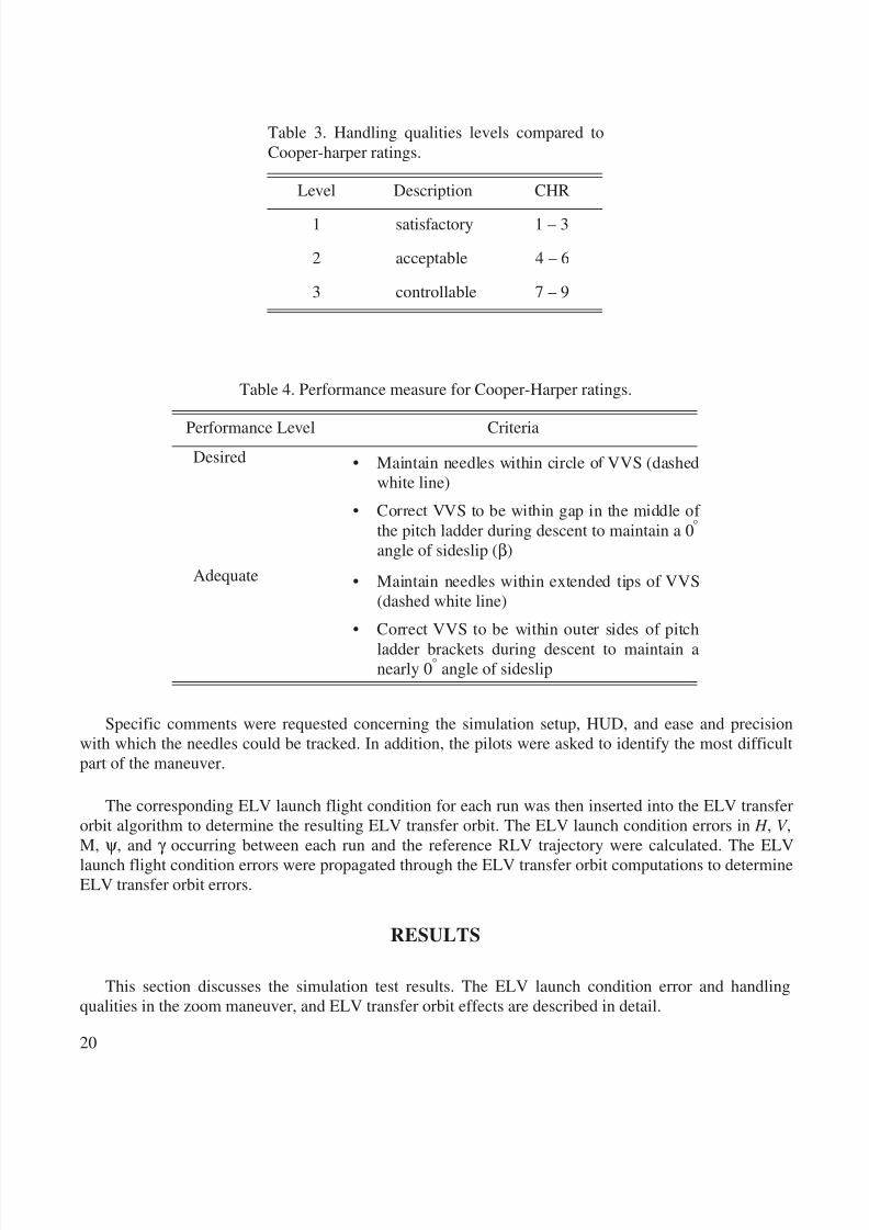
Table 3. Handling qualities levels compared toCooper-harper ratings.
Level Description CHR
1 satisfactory 1 – 3
2 acceptable 4 – 6
3 controllable 7 – 9
Table 4. Performance measure for Cooper-Harper ratings.
Performance Level CriteriaDesired • Maintain needles within circle of VVS (dashed
white line)
• Correct VVS to be within gap in the middle of the pitch ladder during descent to maintain a 0 °
angle of sideslip ( β)Adequate • Maintain needles within extended tips of VVS
(dashed white line)
• Correct VVS to be within outer sides of pitchladder brackets during descent to maintain anearly 0 ° angle of sideslip
8/6/2019 Launch Conditions Deviations of Reusable Vehicle
http://slidepdf.com/reader/full/launch-conditions-deviations-of-reusable-vehicle 25/39
21
ELV Launch Condition Error and Handling Qualities in the Zoom Maneuver
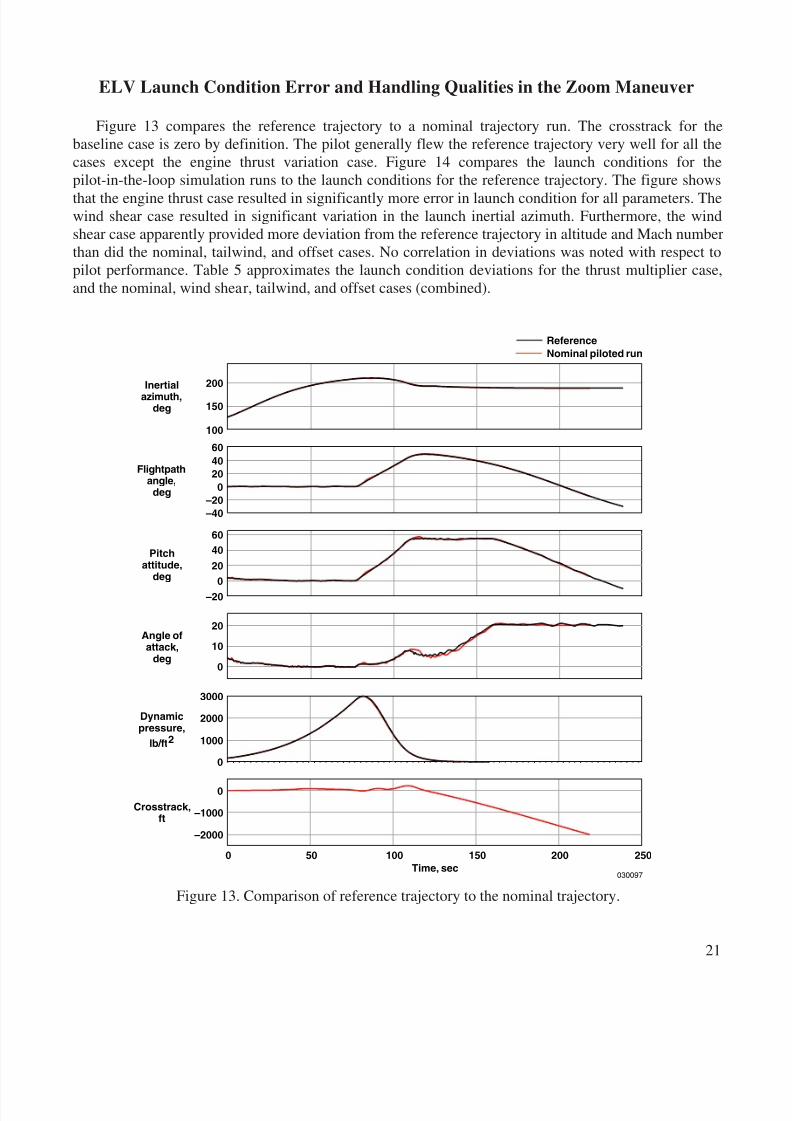
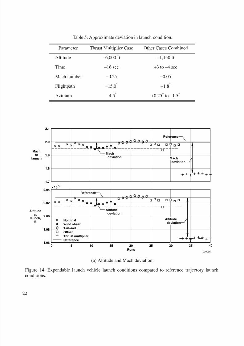
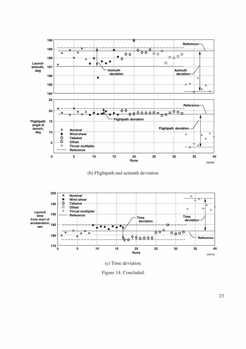
Figure 13 compares the reference trajectory to a nominal trajectory run. The crosstrack for thebaseline case is zero by definition. The pilot generally flew the reference trajectory very well for all thecases except the engine thrust variation case. Figure 14 compares the launch conditions for thepilot-in-the-loop simulation runs to the launch conditions for the reference trajectory. The figure showsthat the engine thrust case resulted in significantly more error in launch condition for all parameters. Thewind shear case resulted in significant variation in the launch inertial azimuth. Furthermore, the windshear case apparently provided more deviation from the reference trajectory in altitude and Mach numberthan did the nominal, tailwind, and offset cases. No correlation in deviations was noted with respect topilot performance. Table 5 approximates the launch condition deviations for the thrust multiplier case,and the nominal, wind shear, tailwind, and offset cases (combined).
ReferenceNominal piloted run
Inertialazimuth,
deg
Flightpathangle,
deg
Pitchattitude,
deg
Angle ofattack,
deg
Dynamicpressure,
lb/ft 2
Crosstrack,ft
200
150
100
604020
0
–40
604020
0–20
20
10
0
3000
2000
1000
0
0
0
–1000
–2000
–20
50 100 150Time, sec
200 250
030097
Figure 13. Comparison of reference trajectory to the nominal trajectory.
8/6/2019 Launch Conditions Deviations of Reusable Vehicle
http://slidepdf.com/reader/full/launch-conditions-deviations-of-reusable-vehicle 26/39
22
Table 5. Approximate deviation in launch condition.
Parameter Thrust Multiplier Case Other Cases Combined
Altitude −6,000 ft −1,150 ft
Time −16 sec +3 to −4 sec
Mach number −0.25 −0.05
Flightpath −15.0° +1.8°
Azimuth −4.5° +0.25° to −1.5°
2.1
Machat
launch
0
Altitudeat
launch,ft
Reference
Reference
5 10 15 20Runs
25 30 35 40
030098
NominalWind shearTailwindOffsetThrust multiplierReference
2.0
1.9
1.8
1.7x 10 5
2.04
2.02
2.00
1.98
1.96
Machdeviation
Altitudedeviation
Altitudedeviation
Machdeviation
(a) Altitude and Mach deviation.
Figure 14. Expendable launch vehicle launch conditions compared to reference trajectory launchconditions.
8/6/2019 Launch Conditions Deviations of Reusable Vehicle
http://slidepdf.com/reader/full/launch-conditions-deviations-of-reusable-vehicle 27/39
23
Launchazimuth,
deg
Flightpathangle atlaunch,
deg
0
Reference
5 10 15 20Runs
25 30 35 40
030099
Azimuthdeviation
Azimuthdeviation
Reference190
189
188
187
186
185
184
25
20
15
10
5
Flightpath deviation
Flightpath deviationNominalWind shearTailwindOffsetThrust multiplierReference
(b) Flightpath and azimuth deviation.
Launchtime
from start ofacceleration,
sec
0
Reference
5 10 15 20Runs
25 30 35 40
030100
Timedeviation
Timedeviation
200
195
190
185
180
175
NominalWind shearTailwindOffsetThrust multiplierReference
(c) Time deviation.
Figure 14. Concluded.
8/6/2019 Launch Conditions Deviations of Reusable Vehicle
http://slidepdf.com/reader/full/launch-conditions-deviations-of-reusable-vehicle 28/39
24
For comparison, deviations in the X-15 program were documented in reference 5 as 2 percent inaltitude, corresponding to approximately 4000 ft for the profile in this study, and 2 °– 3° in heading.
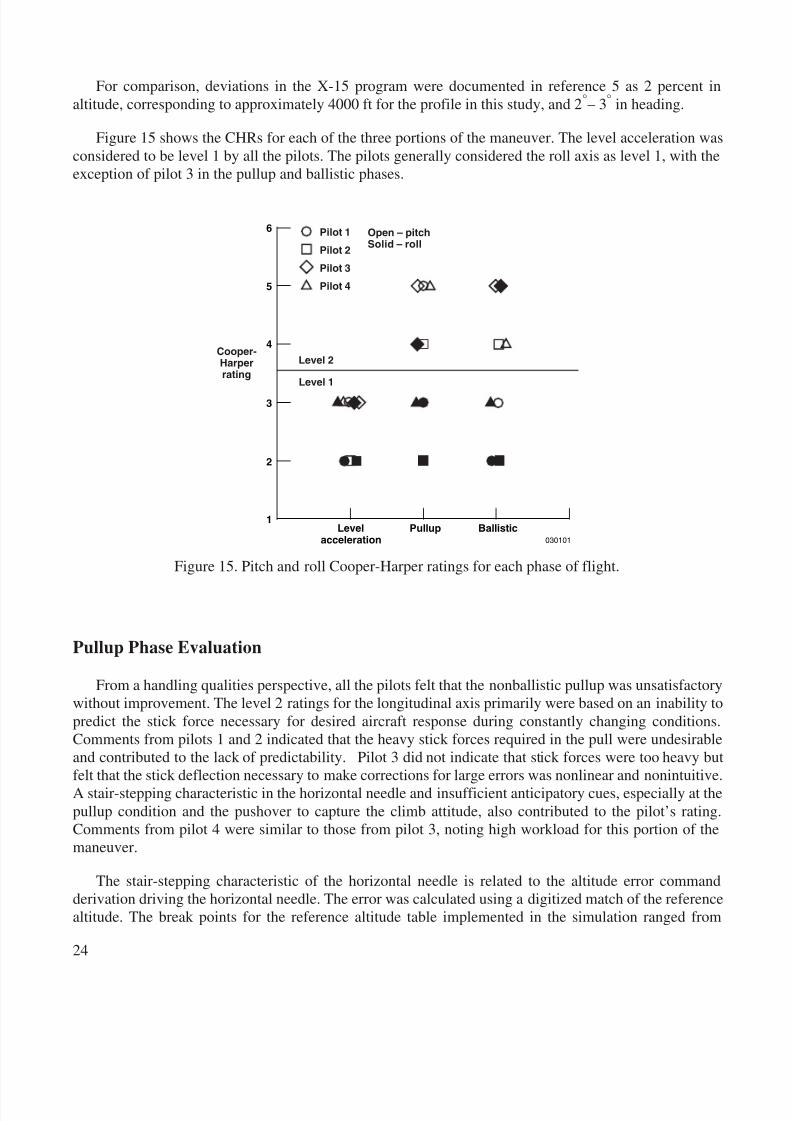
Figure 15 shows the CHRs for each of the three portions of the maneuver. The level acceleration wasconsidered to be level 1 by all the pilots. The pilots generally considered the roll axis as level 1, with theexception of pilot 3 in the pullup and ballistic phases.
Pullup Phase Evaluation
From a handling qualities perspective, all the pilots felt that the nonballistic pullup was unsatisfactorywithout improvement. The level 2 ratings for the longitudinal axis primarily were based on an inability topredict the stick force necessary for desired aircraft response during constantly changing conditions.Comments from pilots 1 and 2 indicated that the heavy stick forces required in the pull were undesirableand contributed to the lack of predictability. Pilot 3 did not indicate that stick forces were too heavy butfelt that the stick deflection necessary to make corrections for large errors was nonlinear and nonintuitive.A stair-stepping characteristic in the horizontal needle and insufficient anticipatory cues, especially at thepullup condition and the pushover to capture the climb attitude, also contributed to the pilot’s rating.Comments from pilot 4 were similar to those from pilot 3, noting high workload for this portion of themaneuver.
The stair-stepping characteristic of the horizontal needle is related to the altitude error commandderivation driving the horizontal needle. The error was calculated using a digitized match of the referencealtitude. The break points for the reference altitude table implemented in the simulation ranged from
1
2
3
4
5
6
Levelacceleration
Pullup Ballistic030101
Open – pitchSolid – roll
Level 2
Level 1
Cooper-Harperrating
Pilot 1
Pilot 2
Pilot 3
Pilot 4
Figure 15. Pitch and roll Cooper-Harper ratings for each phase of flight.
8/6/2019 Launch Conditions Deviations of Reusable Vehicle
http://slidepdf.com/reader/full/launch-conditions-deviations-of-reusable-vehicle 29/39
25
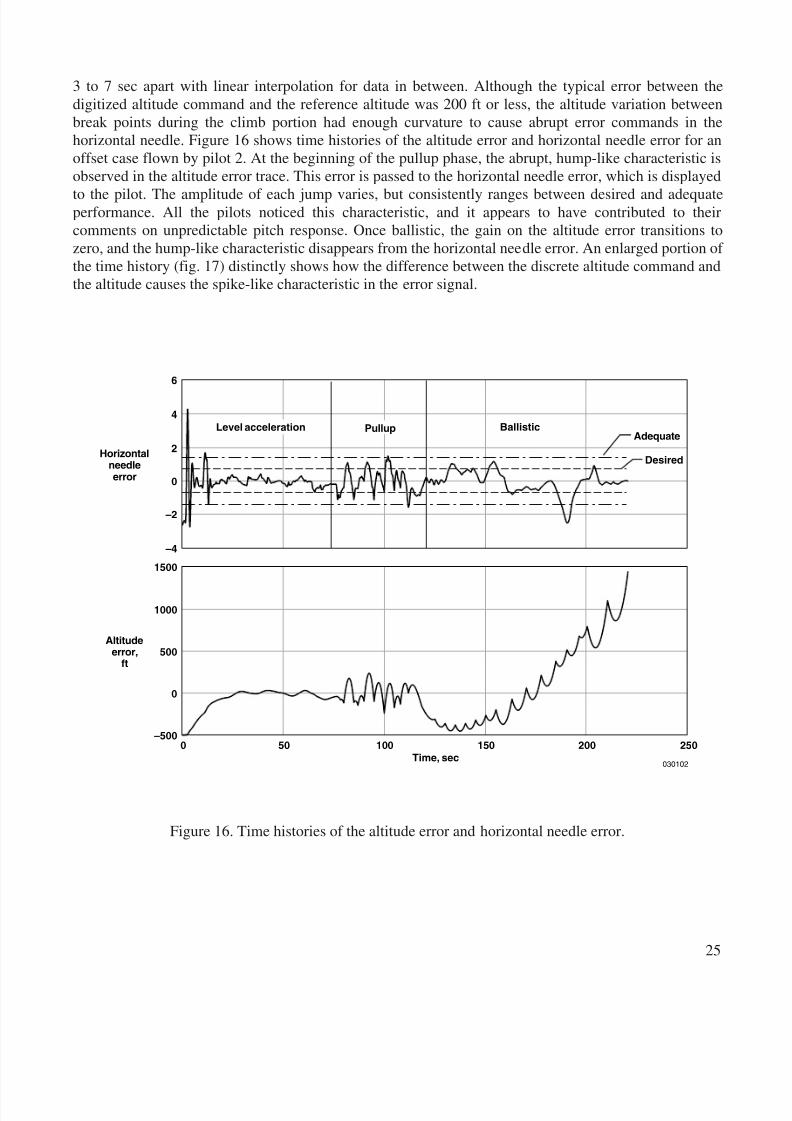
3 to 7 sec apart with linear interpolation for data in between. Although the typical error between thedigitized altitude command and the reference altitude was 200 ft or less, the altitude variation betweenbreak points during the climb portion had enough curvature to cause abrupt error commands in thehorizontal needle. Figure 16 shows time histories of the altitude error and horizontal needle error for anoffset case flown by pilot 2. At the beginning of the pullup phase, the abrupt, hump-like characteristic isobserved in the altitude error trace. This error is passed to the horizontal needle error, which is displayed
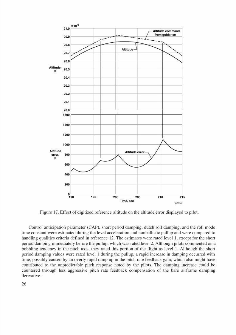
to the pilot. The amplitude of each jump varies, but consistently ranges between desired and adequateperformance. All the pilots noticed this characteristic, and it appears to have contributed to theircomments on unpredictable pitch response. Once ballistic, the gain on the altitude error transitions tozero, and the hump-like characteristic disappears from the horizontal needle error. An enlarged portion of the time history (fig. 17) distinctly shows how the difference between the discrete altitude command andthe altitude causes the spike-like characteristic in the error signal.
Ballistic
50 100Time, sec
030102
6
4
2
0
Horizontalneedleerror
Altitudeerror,
ft
–2
–4
1500
1000
500
0
–5000 150 200 250
Adequate
Desired
Level acceleration Pullup
Figure 16. Time histories of the altitude error and horizontal needle error.
8/6/2019 Launch Conditions Deviations of Reusable Vehicle
http://slidepdf.com/reader/full/launch-conditions-deviations-of-reusable-vehicle 30/39
26
Control anticipation parameter (CAP), short period damping, dutch roll damping, and the roll mode
time constant were estimated during the level acceleration and nonballistic pullup and were compared tohandling qualities criteria defined in reference 12. The estimates were rated level 1, except for the shortperiod damping immediately before the pullup, which was rated level 2. Although pilots commented on abobbling tendency in the pitch axis, they rated this portion of the flight as level 1. Although the shortperiod damping values were rated level 1 during the pullup, a rapid increase in damping occurred withtime, possibly caused by an overly rapid ramp up in the pitch rate feedback gain, which also might havecontributed to the unpredictable pitch response noted by the pilots. The damping increase could becountered through less aggressive pitch rate feedback compensation of the bare airframe dampingderivative.
Altitude commandfrom guidance
Altitude
Altitude error
21.0x 10 4
20.9
20.8
20.7
20.6
20.5Altitude,ft
20.4
20.3
20.2
20.1
20.01600
1400
1200
1000
800Altitude
error,ft
Time, sec
600
400
200
0195190 200 205 210
030103
215
Figure 17. Effect of digitized reference altitude on the altitude error displayed to pilot.
8/6/2019 Launch Conditions Deviations of Reusable Vehicle
http://slidepdf.com/reader/full/launch-conditions-deviations-of-reusable-vehicle 31/39
27
Ballistic Phase Evaluation
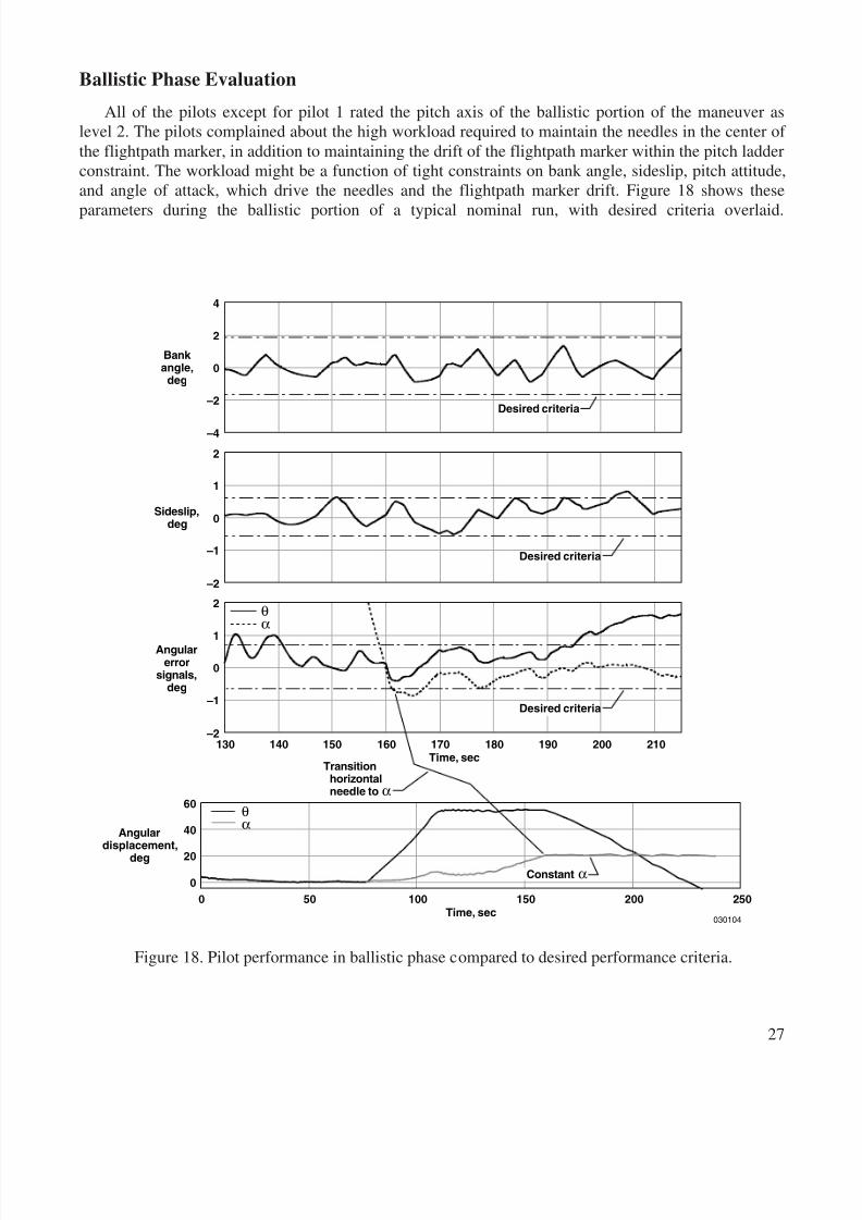
All of the pilots except for pilot 1 rated the pitch axis of the ballistic portion of the maneuver aslevel 2. The pilots complained about the high workload required to maintain the needles in the center of the flightpath marker, in addition to maintaining the drift of the flightpath marker within the pitch ladderconstraint. The workload might be a function of tight constraints on bank angle, sideslip, pitch attitude,and angle of attack, which drive the needles and the flightpath marker drift. Figure 18 shows these
parameters during the ballistic portion of a typical nominal run, with desired criteria overlaid.
140130 160 180 200
Transitionhorizontalneedle to α
500 100 150 200 250
030104
θα
Time, sec
Time, sec
Angulardisplacement,
deg
Angularerror
signals,deg
4
2
0
–2
–4
2
1
0
–1
–2
2
1
0
–1
–2
Bank angle,
deg
Sideslip,deg
150 170 190 210
Desired criteria
Desired criteria
θα
60
40
20
0Constant α
Desired criteria
Figure 18. Pilot performance in ballistic phase compared to desired performance criteria.
8/6/2019 Launch Conditions Deviations of Reusable Vehicle
http://slidepdf.com/reader/full/launch-conditions-deviations-of-reusable-vehicle 32/39
28
The constraints show that desired criteria translate to be less than a 2 ° bank-angle deviation, 0.7 °
pitch-attitude and angle-of-attack deviations, and a 0.6 ° sideslip deviation. The performance levels weremet but required a lot of concentration. Although tight constraints on these parameters probably arenecessary until after the launch occurs, whether or not the constraints in this study are too restrictive isunclear. After the ELV launch occurs, some of these constraints might be relaxed. Pilots 2 and 4 notedsome lag in the horizontal needle, although this factor did not significantly influence the ratings. Pilot 3
indicated that the stick input required to correct large errors in the needles was not intuitively obvious.
Most Difficult Phase
The pilots disagreed on the most difficult phase of the maneuver. The majority of the pilots identifiedthe pullup portion as the most difficult, whereas pilot 2 felt that it was the ballistic portion. No adversecharacteristics were noted for the transitions in the needles generated within the guidance algorithm.
Display Comments
All the pilots commented on issues related to the display. Most felt that the display for controllingsideslip on the ballistic portion was inadequate. They felt corrections to maintain performance levelswere nonintuitive and required more concentration than was desired. In addition, pilots 1 and 4mentioned that a launch condition predictor from the current state would be advantageous in determiningif the current error state was acceptable. Pilots 2 and 4 felt that a pitch pullup cue would help avoid lagson the pullup and reduce the compensation required during the nonballistic climb. Pilot 3, in addition toexpressing the same opinions as those of pilots 1 and 2, favored a flight director type of display asopposed to the ILS-type needles.
ELV Transfer Orbit Effects
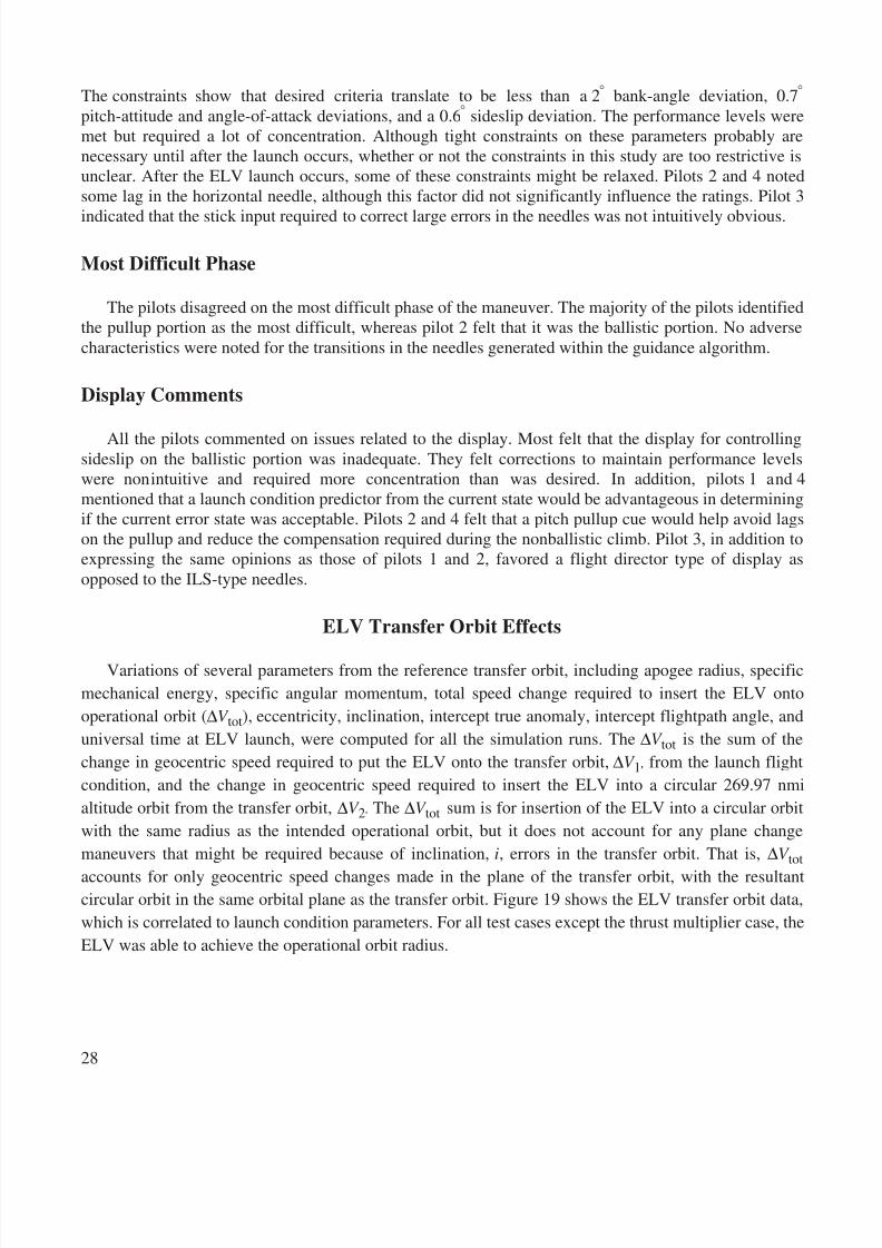
Variations of several parameters from the reference transfer orbit, including apogee radius, specificmechanical energy, specific angular momentum, total speed change required to insert the ELV ontooperational orbit ( ∆V tot), eccentricity, inclination, intercept true anomaly, intercept flightpath angle, anduniversal time at ELV launch, were computed for all the simulation runs. The ∆V tot is the sum of thechange in geocentric speed required to put the ELV onto the transfer orbit, ∆V 1 , from the launch flightcondition, and the change in geocentric speed required to insert the ELV into a circular 269.97 nmialtitude orbit from the transfer orbit, ∆V 2. The ∆V tot sum is for insertion of the ELV into a circular orbitwith the same radius as the intended operational orbit, but it does not account for any plane changemaneuvers that might be required because of inclination, i, errors in the transfer orbit. That is, ∆V tot
accounts for only geocentric speed changes made in the plane of the transfer orbit, with the resultantcircular orbit in the same orbital plane as the transfer orbit. Figure 19 shows the ELV transfer orbit data,which is correlated to launch condition parameters. For all test cases except the thrust multiplier case, theELV was able to achieve the operational orbit radius.
8/6/2019 Launch Conditions Deviations of Reusable Vehicle
http://slidepdf.com/reader/full/launch-conditions-deviations-of-reusable-vehicle 33/39
29
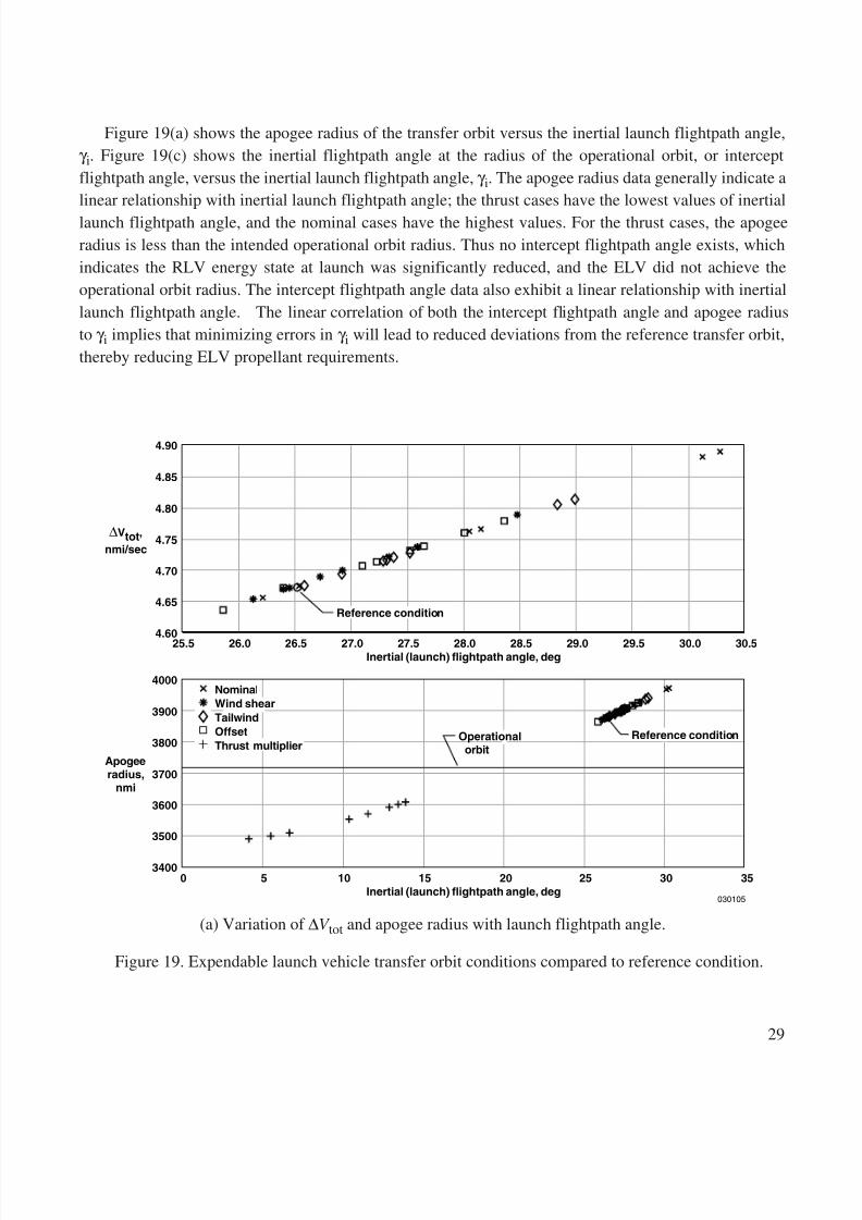
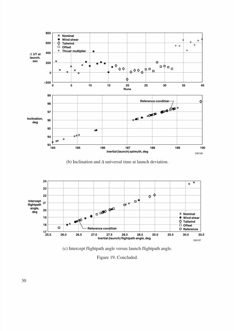
Figure 19(a) shows the apogee radius of the transfer orbit versus the inertial launch flightpath angle,γ i. Figure 19(c) shows the inertial flightpath angle at the radius of the operational orbit, or interceptflightpath angle, versus the inertial launch flightpath angle, γ i. The apogee radius data generally indicate alinear relationship with inertial launch flightpath angle; the thrust cases have the lowest values of inertiallaunch flightpath angle, and the nominal cases have the highest values. For the thrust cases, the apogeeradius is less than the intended operational orbit radius. Thus no intercept flightpath angle exists, whichindicates the RLV energy state at launch was significantly reduced, and the ELV did not achieve theoperational orbit radius. The intercept flightpath angle data also exhibit a linear relationship with inertiallaunch flightpath angle. The linear correlation of both the intercept flightpath angle and apogee radiusto γ i implies that minimizing errors in γ i will lead to reduced deviations from the reference transfer orbit,thereby reducing ELV propellant requirements.
Figure 19. Expendable launch vehicle transfer orbit conditions compared to reference condition.
(a) Variation of ∆V tot and apogee radius with launch flightpath angle.
Apogeeradius,
nmi
∆ Vtot ,nmi/sec
Inertial (launch) flightpath angle, deg0 5 10 15 20 25 30 35
030105
Inertial (launch) flightpath angle, deg
Reference condition
4.90
4.85
4.80
4.75
4.70
4.65
4.6026.0
4000
3900
3800
3700
3600
3500
3400
26.5 27.0 27.5 28.0 28.5 29.0 29.5 30.0 30.525.5
Reference condition
NominalWind shearTailwindOffsetThrust multiplier
Operationalorbit
8/6/2019 Launch Conditions Deviations of Reusable Vehicle
http://slidepdf.com/reader/full/launch-conditions-deviations-of-reusable-vehicle 34/39
30
∆ UT at
launch,sec
184
94
0 5 10 15 20Runs
25 3530 40
030106
185 186 187Inertial (launch) azimuth, deg
188 189 19093
95
96Inclination,deg
97
98
99
800
600
400
200
0
–200
Reference condition
NominalWind shearTailwindOffsetThrust multiplier
(b) Inclination and ∆ universal time at launch deviation.
Interceptflightpath
angle,deg
Inertial (launch) flightpath angle, deg25.5
030107
26.0 26.5 27.0 27.5 28.0 28.5 29.0 29.5 30.0 30.5
Reference condition18
17
19
20
21
22
23
24
NominalWind shearTailwindOffsetReference
(c) Intercept flightpath angle versus launch flightpath angle.
Figure 19. Concluded.
8/6/2019 Launch Conditions Deviations of Reusable Vehicle
http://slidepdf.com/reader/full/launch-conditions-deviations-of-reusable-vehicle 35/39
31
The ∆V tot required for the ELV transfer orbit versus launch inertial flightpath angle (fig. 19(a)) showsthat more ∆V tot was required for most of the runs than was required for the reference trajectory. Thesetrends indicate that in most cases energy deficits were greater than those of the reference trajectory casebecause of variations in the wind vector field, initial offset error at the start of the level acceleration, andpiloting technique for reference trajectory tracking. A few of the runs resulted in less ∆V tot than that of
the reference condition, however, which implies that a more optimal trajectory is possible. Also, therequired ∆V tot apparently is proportional to the launch flightpath angle. Because propellant requirementsare proportional to total ∆V tot, this correlation corroborates the observations of data in the previousparagraph. Minimizing ELV launch errors in γ i is important in reducing the amount of propellantrequired, which impacts ELV sizing requirements.
The importance of controlling inertial launch azimuth is observed in the following results of a planechange maneuver example, and from examination of figure 19(b). This figure shows that the dispersionin launch azimuth causes the transfer orbit inclination, i, to vary between approximately +93.3° and+98.2°. This variation of inclination, compared to the operational orbit inclination ( i = 97.401625 °),would require the ELV to perform an orbit plane change maneuver to achieve the inclination, i, requiredfor the operational orbit. This orbit plane change maneuver would require an additional speed changeincrement, ∆V pc, in addition to the ∆V tot given for each corresponding case (fig. 19(a)), necessitatingadditional propellant, thereby increasing ELV mass and/or reducing the mass available for the payload.
As an example of the geocentric speed change capability required to change the transfer orbitinclination to the intended operational orbit inclination, the data value of ∆i = 1.4° was selected fromtable 6. In the following analysis, the plane change maneuver is assumed to be initiated from the circularorbit with the radius of the intended operational orbit and inclination equal to the inclination of thetransfer orbit. As such, the magnitude of the geocentric speed change required to complete the planechange maneuver, ∆V pc, is given by 9
(14)
where ∆V pc = 0.186 km/sec (.1 nmi/sec), γ op = 0 ≡ flightpath angle on the circular orbit, andV op = 7.6126 km/sec (4.11 nmi/sec) ≡ the geocentric speed required to be on the circular operational orbit
and is given by9
V op = (µ⊕ / Rop )1/2 (15)
where Rop = R⊕ + 500 km ≡ geocentric radius of the operational circular orbit. The magnitude of thespeed change required to change the orbital plane is comparable to the deviation of ∆V tot from thereference condition.
∆V pc2 V op γ op( )sin ∆i 2 ⁄ ( )cos=
8/6/2019 Launch Conditions Deviations of Reusable Vehicle
http://slidepdf.com/reader/full/launch-conditions-deviations-of-reusable-vehicle 36/39
32
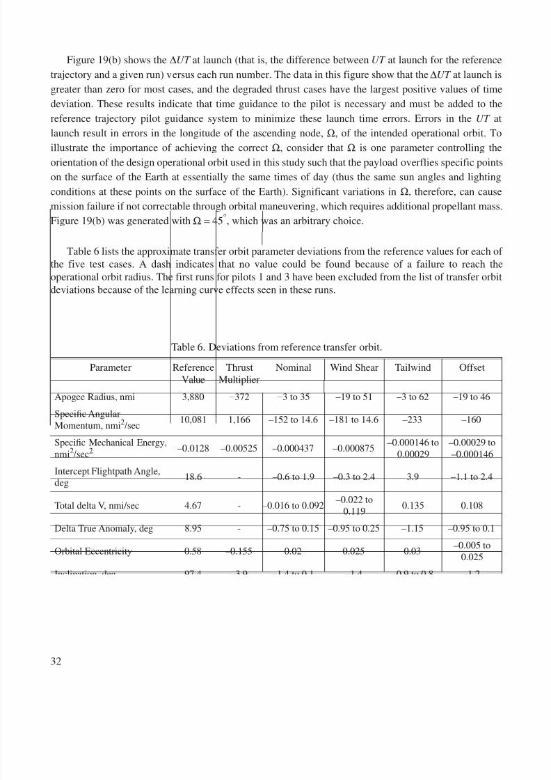
Figure 19(b) shows the ∆UT at launch (that is, the difference between UT at launch for the referencetrajectory and a given run) versus each run number. The data in this figure show that the ∆UT at launch isgreater than zero for most cases, and the degraded thrust cases have the largest positive values of timedeviation. These results indicate that time guidance to the pilot is necessary and must be added to thereference trajectory pilot guidance system to minimize these launch time errors. Errors in the UT at
launch result in errors in the longitude of the ascending node, Ω, of the intended operational orbit. Toillustrate the importance of achieving the correct Ω, consider that Ω is one parameter controlling theorientation of the design operational orbit used in this study such that the payload overflies specific pointson the surface of the Earth at essentially the same times of day (thus the same sun angles and lightingconditions at these points on the surface of the Earth). Significant variations in Ω, therefore, can causemission failure if not correctable through orbital maneuvering, which requires additional propellant mass.Figure 19(b) was generated with Ω = 45°, which was an arbitrary choice.
Table 6 lists the approximate transfer orbit parameter deviations from the reference values for each of the five test cases. A dash indicates that no value could be found because of a failure to reach theoperational orbit radius. The first runs for pilots 1 and 3 have been excluded from the list of transfer orbitdeviations because of the learning curve effects seen in these runs.
Table 6. Deviations from reference transfer orbit.
Parameter ReferenceValue
ThrustMultiplier
Nominal Wind Shear Tailwind Offset
Apogee Radius, nmi 3,880 −372 −3 to 35 –19 to 51 –3 to 62 –19 to 46
Specic AngularMomentum, nmi 2/sec 10,081 1,166 –152 to 14.6 –181 to 14.6 –233 –160
Specic Mechanical Energy,nmi2/sec2 –0.0128 –0.00525 –0.000437 –0.000875 –0.000146 to
0.00029–0.00029 to–0.000146
Intercept Flightpath Angle,deg 18.6 - –0.6 to 1.9 –0.3 to 2.4 3.9 –1.1 to 2.4
Total delta V, nmi/sec 4.67 - –0.016 to 0.092 –0.022 to0.119 0.135 0.108
Delta True Anomaly, deg 8.95 - –0.75 to 0.15 –0.95 to 0.25 –1.15 –0.95 to 0.1
Orbital Eccentricity 0.58 –0.155 0.02 0.025 0.03 –0.005 to0.025
Inclination, deg 97.4 –3.9 –1.4 to 0.1 –1.4 –0.9 to 0.8 –1.2
Time of Flight, sec 201 - –15 to 4 –17 to 5 –21 –17 to 1
Intercept True Anomaly, deg 165.45 - –1 to 0.25 –1.3 to 0.4 –1.6 –1.2 to 0.1
Delta Universal Time atLaunch, sec - 680 220 210 160 203
8/6/2019 Launch Conditions Deviations of Reusable Vehicle
http://slidepdf.com/reader/full/launch-conditions-deviations-of-reusable-vehicle 37/39
33
FUTURE RESEARCH
Improving the handling qualities during the zoom maneuver potentially could improve pilotperformance. Based on the results of this study, the following improvements are suggested:
1. Implement display modications on pullup, pushover, and launch cues.2. Implement less aggressive rate feedback gain increases during the climb portion.
3. Smooth the digitized altitude used in the guidance algorithm by either decreasing the time intervalbetween break points during the climb and ballistic portions, or using a curved t instead of alinear t between break points.
Some additional research not covered in this study would be beneficial to the RASCAL concept.Development of a simple autopilot to perform the trajectory (described in this study) could be used tocompare the ELV launch condition deviation with the pilot-in-the-loop deviation. As previously stated,the RASCAL proposal calls for the ELV to deliver a payload to a sun synchronous orbit, which results inan RLV time constraint. The investigation of guidance concepts, which result in the ELV launch at agiven time, as well as a position and azimuth in space, would be beneficial. Results from this study implythat atmospheric temperature variations and their influence on thrust must be accounted for within theguidance algorithm. The investigation of guidance algorithms, which make real-time adjustments duringthe level acceleration and climb to minimize launch condition errors based on reduced thrust levels,would also be of interest. Use of trajectory optimization algorithms would be beneficial to thedevelopment of these guidance concepts.
CONCLUSIONS
An existing Mach-2.5, fighter-type simulation at the NASA Dryden Flight Research Center wasmodified to simulate a reusable launch vehicle (RLV) in support of the Responsive Access, Small Cargo,and Affordable Launch (RASCAL) program. This simulation was used to quickly evaluateexo-atmospheric zoom climb profiles flown by four research pilots. Guidance was displayed to the pilotsby means of a horizontal and vertical instrument landing system (ILS) type needle. The guidance schemedriving these needles was a function of a reference altitude, pitch attitude, and angle of attack for thehorizontal needle, and a function of crosstrack error, crosstrack rate, and bank angle for the verticalneedle. Differences in Mach, flightpath angle, altitude, and inertial azimuth of a projected launch pointbetween the reference trajectory and the pilot-flown trajectory were documented. Of the five test cases
flown—nominal, wind shear, tailwind, initial altitude and crosstrack offset, and thrust multiplier(–3-percent reduced net thrust)—only the thrust multiplier case generated significant deviations from thereference trajectory. These deviations were caused by the reduced energy state of the RLV. The pitchaxis handling qualities during the maneuver generally were rated level 1 for the level acceleration, andlevel 2 for the pullup and ballistic portions of the maneuver. The roll axis generally was rated level 1 forall phases of the maneuver. Suggestions for improving the pilot displays include a pitch pullup cue,which would allow pilots to anticipate when the pullup begins, and a launch cue, which would allowpilots to minimize errors while establishing a steady-state condition at launch.
8/6/2019 Launch Conditions Deviations of Reusable Vehicle
http://slidepdf.com/reader/full/launch-conditions-deviations-of-reusable-vehicle 38/39
34
At the conditions of the projected expendable launch vehicle (ELV) launch for each run, a rocket burnwas applied to transfer the ELV to a desired operational orbit. Differences between the transfer orbitresulting from a given run and the transfer orbit resulting from a launch at the reference trajectory launchflight condition were calculated. These differences form a basis for bounding the sizing of thesecond-stage ELV design. For the thrust multiplier case, the most sensitive of the test cases investigated,the ELV launch energy was too low for the ELV to reach the operational orbit radius. For the remainingtest cases, the errors in the ELV launch condition were small enough to provide a transfer orbit to thegeocentric radius of the operational orbit for the payload. The most sensitive and critical RLV parametersat the ELV launch were inertial flightpath angle and inertial azimuth.
REFERENCES
1. Defense Advanced Research Projects Agency, Responsive Access, Small Cargo, & Affordable Launch (RASCAL) Demonstration Program , Phase I, Program Solicitation 02–02, Dec. 10, 2001.
2. Plattner, C. M., “Space Training Flights in NF-104A Near,” Aviation Week & Space Technology ,August 9, 1965, pp. 80–85.
3. Holleman, Euclid C., and Elmor J. Adkins, “Contributions of the X-15 Program to Lifting EntryTechnology,” Journal of Aircraft , vol. 1, no. 6, Nov.–Dec. 1964, pp. 360–366.
4. Fischel, Jack, and Lannie D. Webb, Flight-Informational Sensors, Display, and Space Control of the X-15 Airplane for Atmospheric and Near-Space Flight Missions , NASA TN D-2407, Aug. 1964.
5. Holleman, Euclid C., Piloting Performance During the Boost of the X-15 Airplane to High Altitude ,NASA TN D-2289, April 1964.
6. Jarvis, Calvin R., and Elmor J. Adkins, Operational Experience With X-15 Reaction Controls ,NASA TM X-56002, April 21, 1964.
7. Jarvis, Calvin R., and Wilton P. Lock, Operational Experience With the X-15 Reaction Control and Reaction Augmentation Systems , NASA TN D-2864, June 1965.
8. Henneberry, Hugh M., and Christopher A. Snyder, Analysis of Gas Turbine Engines Using Water and Oxygen Injection to Achieve High Mach Numbers and High Thrust , NASA TM 106270, July1993.
9. Vallado, David A., and Wayne D. McClain, Fundamentals of Astrodynamics and Applications ,
Space Technology Series, Wiley J. Larson, ed., The McGraw-Hill Companies, Inc., 1997.10. Wertz, James R., and Wiley J. Larson, eds., Space Mission Analysis and Design , Third Edition,
Space Technology Series, Microcosm Press and Kluwer Academic Publishers, 1999.
11. Cooper, George E., and Robert P. Harper, Jr., The Use of Pilot Rating in the Evaluation of Aircraft Handling Qualities , NASA TN D-5153, April 1969.
12. Flying Qualities of Piloted Vehicles , U. S. Department of Defense, MIL-STD 1797, March 31, 1987.
8/6/2019 Launch Conditions Deviations of Reusable Vehicle
http://slidepdf.com/reader/full/launch-conditions-deviations-of-reusable-vehicle 39/39
REPORT DOCUMENTATION PAGE Form ApprovedOMB No. 0704-0188
Public reporting burden for this collection of information is estimated to average 1 hour per response, including the time for reviewing instructions, searching existing data sources, gathering andmaintaining the data needed, and completing and reviewing the collection of information. Send comments regarding this burden estimate or any other aspect of this collection of information,including suggestions for reducing this burden, to Washington Headquarters Services, Directorate for Information Operations and Report s, 1215 Jefferson Davis Highway, Suite 1204, Arlington,VA 22202-4302, and to t he Ofce of Management and Budget, Paperwork Reduction Project (0704-0188), Washington, DC 20503.
1. AGENCY USE ONLY (Leave blank) 2. REPORT DATE 3. REPORT TYPE AND DATES COVERED
4. TITLE AND SUBTITLE 5. FUNDING NUMBERS
6. AUTHOR(S)
8. PERFORMING ORGANIZATIONREPORT NUMBER
7. PERFORMING ORGANIZATION NAME(S) AND ADDRESS(ES)
9. SPONSORING/MONITORING AGENCY NAME(S) AND ADDRESS(ES) 10. SPONSORING/MONITORING
AGENCY REPORT NUMBER
11. SUPPLEMENTARY NOTES
12a. DISTRIBUTION/AVAILABILITY STATEMENT 12b. DISTRIBUTION CODE
13. ABSTRACT (Maximum 200 words)
14. SUBJECT TERMS 15. NUMBER OF PAGES
16. PRICE CODE
Launch Condition Deviations of Reusable Launch Vehicle Simulations in
Exo-Atmospheric Zoom Climbs710-85-14-SE-47-00-DVI
Peter H. Urschel and Timothy H. Cox
NASA Dryden Flight Research CenterP.O. Box 273Edwards, California 93523-0273
H-2533
National Aeronautics and Space AdministrationWashington, DC 20546-0001 NASA/TM-2003-212023
The Defense Advanced Research Projects Agency has proposed a two-stage system to deliver a smallpayload to orbit. The proposal calls for an airplane to perform an exo-atmospheric zoom climb maneuver, fromwhich a second-stage rocket is launched carrying the payload into orbit. The NASA Dryden Flight ResearchCenter has conducted an in-house generic simulation study to determine how accurately a human-pilotedairplane can deliver a second-stage rocket to a desired exo-atmospheric launch condition. A high-performance,ghter-type, xed-base, real-time, pilot-in-the-loop airplane simulation has been modied to perform exo-atmospheric zoom climb maneuvers. Four research pilots tracked a reference trajectory in the presence of winds, initial offsets, and degraded engine thrust to a second-stage launch condition. These launch conditionshave been compared to the reference launch condition to characterize the expected deviation. At each launchcondition, a speed change was applied to the second-stage rocket to insert the payload onto a transfer orbit tothe desired operational orbit. The most sensitive of the test cases was the degraded thrust case, yielding second-stage launch energies that were too low to achieve the radius of the desired operational orbit. The handlingqualities of the airplane, as a rst-stage vehicle, have also been investigated.
Exo-atmospheric zoom climb maneuver, Expendable launch vehicle,Pilot-in-the-loop simulation, Reusable launch vehicle, Transfer orbit
39
September 2003 Technical Memorandum
Also presented at the AIAA Atmospheric Flight Mechanics Conference and Exhibit, Aug. 11–14, 2003,Austin, TX.
Unclassied—UnlimitedSubject Category 15
This report is available at http://www.dfrc.nasa.gov/DTRS/