Lattice Tower Design of Offshore Wind Turbine Support Structures
135
Wei Gong Lattice Tower Design of Offshore Wind Turbine Support Structures Trondheim, June/2011 Master´s thesis NTNU Norwegian University of Science and Technology Faculty of Engineering Science and Technology Department of Civil and Transport Engineering
Transcript of Lattice Tower Design of Offshore Wind Turbine Support Structures

Wei Gong
Lattice Tower Design of Offshore Wind Turbine Support Structures Trondheim, June/2011
Mas
ter´s
thes
is
NT
NU
Nor
weg
ian
Uni
vers
ity o
f Sc
ienc
e an
d Te
chno
logy
Facu
lty o
f Eng
inee
ring
Scie
nce
and
Tech
nolo
gyD
epar
tmen
t of C
ivil
and
Tran
spor
t Eng
inee
ring

ii
NORWEGIAN UNIVERSITY OF SCIENCE AND TECHNOLOGY
DEPARTMENT OF CIVIL AND TRANSPORT ENGINEERING
Report Title:
Lattice Tower Design of Offshore Wind Turbine Support Structures
Date: 14/JUNE/2011
Number of pages (incl. appendices):
Master Thesis × Project Work
Name: Wei Gong
Professor in charge/supervisor: Geir Moe, Daniel Zwick
Other external professional contacts/supervisors:
Abstract:
Optimal design of support structure including foundation and turbine tower is among the most critical
challenges for offshore wind turbine. With development of offshore wind industry heading for deeper ocean
areas, new support structural concept such as a full lattice tower could be proven to be more advantageous than
others when consideration of cost, safety and even environment aspects, etc are taken into.
This thesis first gave introduction of present industrial applications of hybrid support structural concept
combing a lattice foundation and monotower in relatively deep water areas before the presenting and
introduction of challenges with the transition piece component. Conceptual model of transition piece design
for a full lattice tower support structure proposal was discussed extensively which included consideration of
structural form, functional requirement, mechanical condition, etc. A mechanical model of transition piece
with regards to boundary condition and load conditions was also provided. Design and analysis of two
different types of transition piece models under various load conditions were performed during preliminary
design and with conclusion drawn, a refined final design of transition piece model for the full lattice tower
support structural concept which has also included more practical aspects was assessed through investigation
of its performance under varying load conditions and different load cases. This refined final design was found
to be the most optimal design fulfilling all relevant requirements at a comparable structural cost. Conclusion
and recommendation was therefore given in the last part.
This thesis work is serving for a novel proposal of support structural concept for future offshore wind industry
and relevant present experience is in fact nonexistent. The work applied present industrial information of
hybrid support structure as basis along with consideration of offshore wind turbine structural and operational
mechanism and their respective requirement. Structural analysis of transition piece design was conducted by
means of finite element analysis technique and structural load conditions were simulated through up-to-date
numerical modeling code for offshore wind turbine structure. Due to absence of relevant verification sources,
advice and correction of the thesis content is much appreciated.
Keywords:
1. Offshore Wind Turbine
2. Wind Turbine Support Structure
3. Transition Piece
4. Lattice Tower
_________________________________________
(signature)

iii
Faculty of Engineering Science and Technology Department of Civil and Transport Engineering
Date:
page 1 of 3 pages
MASTER THESIS (TBA4920 Marin Byggteknikk, master thesis)
Spring 2011
for
Wei Gong
Lattice Tower Design of Offshore Wind Turbine Support Structures
BACKGROUND
For offshore wind turbines to be installed in less than 70m water depth, bottom-fixed
support structures will probably be used. Nearly all bottom fixed turbines have up to
now been installed in moderate water depth, say 10-25m and then usually a monopile
foundation has been preferred, but in a depth of 30-70m lattice tower geometry will
probably turn out to be advantageous. A lattice topology could be used for the entire
support structure between sea bottom and turbine nacelle or for the lower part of the
tower only. So far, only the latter, so-called hybrid concepts have been installed
offshore. These concept permits the use of a standard tubular tower for the upper part
but a complicated transition piece is needed at the intersection to the lattice. The fully
lattice tower concept is a relatively new proposal for support structures and one critical
question in the design of such a structure is the design of the tower top and the
interaction between it and the nacelle.
TASK DESCRIPTION
The student shall give a brief overview over existing support structure designs based on
space frame/lattice tower topology and define the functional requirements for features
installed or occurring at the intersection between the tower and nacelle, typically for
transmission of electrical energy, structural loads and yaw control.
Then one or a few tower top designs should be analyzed in detail for the most critical
cases to estimate stresses and deflections. Also attention should be paid to fatigue and if
feasible some fatigue life estimates made. Abaqus might be a suitable computational
tool for the job, but the student is free to make other choices.
iv
GENERAL ABOUT CONTENT, WORK AND PRESENTATION
The task description for the master thesis is meant as a framework for the work of the
candidate. Adjustments might be done as the work progresses. Tentative changes must
be done in cooperation and agreement with the supervisor and professor in charge at the
Department. (Also including external cooperative partners where this is applicable).
In the evaluation thoroughness in the work will be emphasized, as will be
documentation of independence in assessments and conclusions. Furthermore the
presentation (report) should be well organized and edited; providing clear, precise and
orderly descriptions without being unnecessary voluminous.
The report shall include: (templates are found on http://www.ntnu.no/bat/skjemabank)
Standard report front page.
Title page with abstract and keywords (signed by the student).
Summary and acknowledgement. Table of content including list of symbols,
figures, tables and enclosures. If useful and applicable a list of important terms
and abbreviations should be included.
The main text.
Clear and complete references to material used, both in text and figures/tables.
This also applies for personal and/or oral communication and information.
Text of the Thesis (these pages) signed by the professor in charge.
The report must have a complete page numbering.
The thesis may possibly be written as a scientific article. The report must come
with report front and title pages and, if necessary, with appendices that
document the work performed in the process of writing of the article.
Submission procedure
The complete, original report (un-bounded).
Two copies (bounded).
If applicable: X additional copies if agreed upon for instance with external
partner (to be paid for by the Department or the external partner)
CD with the complete report (pdf-format) and all assisting or underlying
material.
A brief (one to two A4 pages including possible illustrations) popular science
summary of the work, aiming at publication on the Department’s web-site.
Include a copy of this html document on the CD. Template is found on:
http://www.ntnu.no/bat/skjemabank
The summary shall include the objectives of the work, explain how the work has been
conducted, present the main results achieved and give the main conclusions of the work.
Advice and guidelines for writing of the report is given in: “Writing Reports” by Øivind
Arntsen. Additional information on report writing is found in “Råd og retningslinjer for
rapportskriving ved prosjekt og masteroppgave ved Institutt for bygg, anlegg og
transport” (In Norwegian). Both are posted on http://www.ntnu.no/bat/skjemabank
TBA4920 Marin Byggteknikk, Master Thesis 2 Master thesis for Wei Gong, Spring 2011

v
Documentation collected during the work, with support from the Department, shall be
handed in to the Department together with the report.
According to the current laws and regulations at NTNU, the report is the property of
NTNU. The report and associated results can only be used following approval from
NTNU (and external cooperation partner if applicable). The Department has the right to
make use of the results from the work as if conducted by a Department employee, as
long as other arrangements are not agreed upon beforehand.
Tentative agreement on external supervision, work outside NTNU, economic
support etc
Separate description to be developed, if and when applicable.
Health, safety and environment (HSE)
The health, safety and environmental (HSE) work at NTNU shall constitute continuous
and systematic efforts that are integrated into the primary activities. NTNU emphasizes
the safety for the individual employee and student. The individual safety shall be in the
forefront and no one shall take unnecessary chances in carrying out the work.
Information in English on HSE is given on: http://www.ntnu.no/hse. In particular, if the
student is to participate in field work, visits, field courses, excursions etc. during the
Master Thesis work, he/she shall make himself/herself familiar with the Fieldwork
HSE Guidelines http://www.ntnu.no/hms/retningslinjer/HMSR07E.doc. General HSE
provisions that apply in all laboratories and workshops are given on:
http://www.ntnu.no/hse/labhandbook.
The students do not have a full insurance coverage as a student at NTNU. If a student
wants the same insurance coverage as the employees at the university, he/she must
establish an individual travel and personal injury insurance. More information about
students and insurance is found on the faculty HSE page on:
http://www.ntnu.no/ivt/adm/hms/. (Documents are in Norwegian only, ask the
supervisor to explain).
Start and submission deadlines
The work on the Master Thesis starts on January 17, 2011
The thesis report original (not bounded) and 2 bounded copies and the CD as described
above shall be submitted at the latest on June 14, 2010 at 1500 hrs.
Professor in charge: Geir Moe
Other supervisors: Daniel Zwick
Department of Civil and Transport Engineering, NTNU
Date:
Signature
Professor in charge
TBA4920 Marin Byggteknikk, Master Thesis 3 Master thesis for Wei Gong, Spring 2011

vi
DEDICATION
Upon completion of my master study of Coastal and Marine Engineering and
Mangement (CoMEM) under Erasmus Mundus programme funded by European
Parliament, this thesis is dedicated to all those who have helped, supported, shared joy
and gone through difficulties with me during the last two-year period of study. It is also
hoped that this thesis will be able to provide useful information to the exciting offshore
wind industry of my great enthusiasm.
ACKNOWLEDGEMENT
This thesis work was completed within Marine Civil Engineering Group, Department of
Civil and Transport Engineering, NTNU from where a lot of assistance and help is
received. Professor Geir Moe’s approval of this thesis task assignment to me as well as
his guidance, explanation and clarification provided during the period of this work is
very much appreciated. Mr. Daniel Zwick’s fulfillment of supervision of this thesis has
helped proceeding the thesis progress. In addition, Professor Øivind Asgeir Arntsen has
provided much practical help without which the thesis could not be completed in a
smooth progress. Support from the Marine Civil Engineering Group for my
participation of OMAE2011, Rotterdam is also indeed thanked.

vii
PREFACE
By the time being of this thesis work, offshore wind industry is undergoing prosperous
development and advancement which comes out as a call of global energy strategy and
environment issue. One of the most critical challenges for offshore wind turbine
involves the optimal design of support structure including foundation and turbine tower.
With development of offshore wind industry heading for deeper ocean areas, new
support structural concept might be proven to be more advantageous than conventional
types when consideration of cost, safety and even environment aspects, etc are taken
into. This thesis is therefore aiming to support optimal novel support structural design
of future deep water bottom fixed offshore wind turbine.
A full lattice support structure concept ranging from seabed to nacelle assembly has
been proposed for relatively deep water areas, e.g. 30m-70m. This new concept might
be able to provide a better solution for deep water fixed offshore wind turbine but a
critical component connecting this full lattice structure and the upper nacelle assembly,
namely transition piece, has become another critical challenge which has not been
studied so far. This thesis first gave introduction of present industrial applications of
hybrid support structural concept combing a lattice foundation and monotower before
the presenting and introduction of challenges with the transition piece component.
Conceptual model of transition piece design for a full lattice support structure proposal
was discussed extensively later. A mechanical model of transition piece with regards to
boundary condition and load conditions was provided for structural analysis and
numerical modeling purpose. Based on experience from hybrid support structural
concept, design and analysis of two different types of transition piece models under
various load conditions were performed during preliminary design and with conclusion
drawn from this preliminary design phase, a refined final design of transition piece
model for the full lattice support structural concept which has also included more
practical aspects was assessed through investigation of its performance under varying
load conditions and different load cases. This refined final design was found to be the
most optimal design fulfilling all relevant requirements at a comparable structural cost.
Conclusion and recommendation was therefore given in the last part.
viii
TABLE OF CONTENT
1 INTRODUCTION .................................................................................................................................. 1
1.1 Introduction of offshore wind turbine ............................................................................................. 1
1.1.1 Offshore wind development and wind turbine system ............................................................. 1
1.1.2 Wind turbine support structure ................................................................................................ 1
1.1.3 Wind turbine control system .................................................................................................... 2
1.2 Background and content of this work ............................................................................................. 2
1.2.1 Background .............................................................................................................................. 2
1.2.2 Content..................................................................................................................................... 3
1.3 Scope and limitation ........................................................................................................................ 3
2 LATTICE SUPPORT STRUCTURE FOR OFFSHORE WIND TURBINE ......................................... 5
2.1 Introduction of lattice structure ....................................................................................................... 5
2.2 History of lattice tower for onshore wind turbine ........................................................................... 5
2.3 Current application of lattice support structure for offshore wind turbine ...................................... 6
2.3.1 OWEC jacket quattropod for Beatrice demo wind farm .......................................................... 6
2.3.2 OWEC jacket quattropod for Alpha Ventus offshore wind farm ............................................. 7
2.3.3 RAMBØLL jacket for the Upwind project .............................................................................. 8
2.3.4 RAMBØLL jacket for the OC4 project ................................................................................... 8
2.3.5 REpower jacket ........................................................................................................................ 8
2.4 Summary of lattice as support structure for offshore wind turbine ................................................. 9
2.5 Introduction of transition piece ....................................................................................................... 9
2.6 Transition piece for early onshore wind turbine supported by lattice tower ................................. 10
2.7 Transition piece for hybrid offshore wind turbine support structures ........................................... 10
2.7.1 Transition piece for Beatrice demo wind farm ...................................................................... 10
2.7.2 Transition piece for Alpha Ventus offshore wind farm ......................................................... 11
2.7.3 Transition piece for the Upwind and OC4 project ................................................................. 11
2.7.4 Transition piece for REpower jacket in Bremerhaven ........................................................... 11
2.8 Summary of transition piece designs ............................................................................................ 12
3 CONCEPTUAL MODEL OF TRANSITION PIECE .......................................................................... 15
3.1 Geometrical requirement ............................................................................................................... 15
3.2 Functional requirement ................................................................................................................. 16
3.2.1 Power transmission equipment .............................................................................................. 16
3.2.2 Yaw system ............................................................................................................................ 19
3.3 Mechanical requirement ................................................................................................................ 23
3.3.1 Connection with the lattice support structure ........................................................................ 23
3.3.2 Connection with the nacelle assembly ................................................................................... 23
3.4 Mechanical model of transition piece ........................................................................................... 24
3.4.1 Boundary condition ............................................................................................................... 25
3.4.2 Analysis of a full lattice support structure concept ................................................................ 25
3.4.3 Load condition ....................................................................................................................... 31
4 PRELIMINARY DESIGN OF TRANSITION PIECE ........................................................................ 39
4.1 Proposed model ............................................................................................................................. 39
4.1.1 Frame-cylinder model ............................................................................................................ 40
4.1.2 Cone-strut model ................................................................................................................... 41
4.2 Finite element model ..................................................................................................................... 41
4.2.1 Model introduction ................................................................................................................ 41

ix
4.2.2 Boundary condition ............................................................................................................... 42
4.2.3 Loading .................................................................................................................................. 42
4.3 Finite element analysis result ........................................................................................................ 43
4.3.1 Modal analysis ....................................................................................................................... 43
4.3.2 RNA weight ........................................................................................................................... 44
4.3.3 Rotor thrust ............................................................................................................................ 46
4.3.4 Hydrodynamic load ............................................................................................................... 55
4.3.5 Drive train vibration .............................................................................................................. 59
4.3.6 Rotor torque ........................................................................................................................... 59
4.3.7 Yaw moment .......................................................................................................................... 62
4.4 Conclusion .................................................................................................................................... 66
5 FINAL DESIGN OF TRANSITION PIECE ........................................................................................ 69
5.1 Model geometry ............................................................................................................................ 69
5.2 Structural dimension ..................................................................................................................... 70
5.3 Model selection ............................................................................................................................. 72
5.4 Functional fulfillment ................................................................................................................... 73
5.5 Load analysis................................................................................................................................. 73
5.5.1 RNA load ............................................................................................................................... 74
5.5.2 Operation under aero load ...................................................................................................... 76
5.5.3 Operation under aero load with yaw motion .......................................................................... 81
5.5.4 Operation under aero & hydro load at identical wind wave direction ................................... 86
5.5.5 Operation under aero & hydro load with unidentical wind wave direction ........................... 90
5.6 Investigation on more compact design .......................................................................................... 95
5.7 Fatigue ........................................................................................................................................... 96
5.8 Manufacturing ............................................................................................................................... 98
5.9 Conclusion .................................................................................................................................... 98
6 CONCLUSION AND RECOMMENDATION.................................................................................... 99
6.1 Conclusion .................................................................................................................................... 99
6.2 Recommendation ........................................................................................................................ 100
REFERENCE ........................................................................................................................................ 101
APPENDIX I ......................................................................................................................................... 103
APPENDIX II ....................................................................................................................................... 105
APPENDIX III ...................................................................................................................................... 107
APPENDIX IV ...................................................................................................................................... 108
APPENDIX V ....................................................................................................................................... 109
APPENDIX VI ...................................................................................................................................... 113
APPENDIX VII ..................................................................................................................................... 116

x
LIST OF FIGURES
Figure 1.1 Components of a Horizontal Axis Wind Turbine ........................................................................ 2
Figure 2.1 Example of Lattice Tower for Onshore Wind Turbines .............................................................. 5
Figure 2.2 Hybrid Support Structure for Offshore Wind Turbine ................................................................ 6
Figure 2.3 OWEC Jacket Quattropod on Offshore Wind Turbine ............................................................... 7
Figure 2.4 RAMBØLL Jacket Substructure Configuration for Upwind Project .......................................... 8
Figure 2.5 REpower 5MW Wind Turbine on a Jacket Substructure ........................................................... 9
Figure 2.6 Transition Piece of REpower Jacket ........................................................................................ 12
Figure 3.1 Geometrical Profile for Transition Piece ................................................................................... 15
Figure 3.2 Various Geometrical Models for Transition Piece .................................................................... 16
Figure 3.3 Equipment Arrangement in an Onshore Monotower Wind Turbine ......................................... 17
Figure 3.4 Application of J-tube for Power Cable Protection for Offshore Wind Turbine ........................ 18
Figure 3.5 Power Transmission Cable for Offshore Wind Farm ................................................................ 18
Figure 3.6 Power Transmission Cable Layout in Transition Piece ............................................................ 18
Figure 3.7 Different Yawing Concepts ....................................................................................................... 19
Figure 3.8 Configuration of a Roller Bearing System ................................................................................ 20
Figure 3.9 Various Types of Roller Bearing .............................................................................................. 20
Figure 3.10 Configuration of Gliding Bearing System ............................................................................... 21
Figure 3.11 Location of Yaw Drive in REpower 5MW Turbine System ................................................... 22
Figure 3.12 Transition Piece Connection with Yaw Bearing inside the Nacelle Assembly ....................... 24
Figure 3.13 Bolting Connection of Yaw Bearing and Cylinder Flange ...................................................... 24
Figure 3.14 Boundary Condition of Transition Piece Using Spring System .............................................. 25
Figure 3.15 Support Structure Bending Frequency Range ......................................................................... 27
Figure 3.16 Configuration of a Lattice Support Structure for a 5MW Reference Offshore Wind Turbine 28
Figure 3.17 Rotor Nacelle Assembly Weight on Transition Piece ............................................................. 31
Figure 3.18 Stream Tube of Rotor Disk Theory ......................................................................................... 32
Figure 3.19 Rotor Thrust Force on Transition Piece .................................................................................. 33
Figure 3.20 Hydrodynamic Load (Acceleration or Displacement) on Transition Piece ............................. 33
Figure 3.21 Rotor Torque on Transition Piece ........................................................................................... 34
Figure 3.22 Misalignment of Incoming Wind with Rotor Axis .................................................................. 36
Figure 3.23 Yaw Moment on Transition Piece ........................................................................................... 36
Figure 3.24 Mechanical Model of Transition Piece Including Boundary Condition and Various Loads ... 37
Figure 4.1 Methodology for Transition Piece Modeling and Analysis ....................................................... 39
Figure 4.2 Geometrical Configuration Requirement for Transition Piece .................................................. 39
Figure 4.3 Frame-cylinder Transition Piece Model .................................................................................... 40
Figure 4.4 Cone-strut Transition Piece Model ........................................................................................... 40
Figure 4.5 Finite Element Models of Transition Piece ............................................................................... 41
Figure 4.6 Coordination System Illustration .............................................................................................. 42
Figure 4.7 Transition Piece Stress Condition under RNA Weight ............................................................. 44
Figure 4.8 Oscillation of Vertical Load on Support Structure Top due to RNA Weight with Consideration
of Rotor Aerodynamics .............................................................................................................................. 45
Figure 4.9 Misalignment of Yaw Axis and Mass Centers of Rotor and Nacelle ........................................ 45
Figure 4.10 Transition Piece Response under RNA Weight and Its Induced Moment .............................. 46
Figure 4.11 Thrust Coefficient in Relation to Wind Speed ........................................................................ 47
Figure 4.12 Response of Transition Piece under Theoretical Static Thrust Load ...................................... 48
Figure 4.13 Transition Piece Response under Static Thrust and RNA Load .............................................. 49
Figure 4.14 Time Series of Normal Turbulent Wind with Mean Wind Speed 24m/s and Turbulence
Intensity 15.7% ........................................................................................................................................... 50
Figure 4.15 Theoretical Thrust Load on Rotor Disk .................................................................................. 50
Figure 4.16 Simulated Thrust Load from HAWC2 .................................................................................... 50
Figure 4.17 Structural Response of Frame-cylinder TP under Dynamic Thrust Load ............................... 51
Figure 4.18 Frame-cylinder TP Response under Thrust Load at Max. Negative and Positive Deflection
Time Points ................................................................................................................................................ 52
Figure 4.19 Structural Response of Cone-strut TP under Dynamic Thrust ................................................ 53
Figure 4.20 Cone-strut TP Response under Thrust Load at Max. Negative and Positive Deflection Time
Points .......................................................................................................................................................... 54
Figure 4.21 Power Spectral Density of Simulated Dynamic Thrust Load Time Series ............................. 55
xi
Figure 4.22 Origin and Coordination for Hydrodynamic Load Computation ............................................ 55
Figure 4.23 Water Surface for a Simulated 4.0m Wave Condition ............................................................ 56
Figure 4.24 4.0m Wave Load on Lattice Leg from HAWC2 Simulation ................................................... 56
Figure 4.25 Applying Simulated Wave Load on Lattice Support Structure ............................................... 57
Figure 4.26 Top Displacement of Lattice Support Structure under 4.0m Wave ......................................... 57
Figure 4.27 Water Surface for a Simulated 10m Wave Condition .............................................................57
Figure 4.28 10.0m Wave Load on Lattice Leg from HAWC2 Simulation ................................................. 58
Figure 4.29 Top Displacement of Lattice Support Structure under 10m Wave .......................................... 58
Figure 4.30 Buckling of Trusses below Water Surface of Lattice Support Structure under 10m Wave .... 59
Figure 4.31 Rotor Torque under a Normal Turbulent Wind Condition ...................................................... 60
Figure 4.32 Deformation of Frame-cylinder TP under Rotor Torque ........................................................ 60
Figure 4.33 Frame-cylinder TP Stress Condition at Time Point of Max. Stress under Rotor Torque ........ 61
Figure 4.34 Deformation of Cone-strut TP under Rotor Torque ................................................................ 61
Figure 4.35 Z-displacement of Cone-strut TP under Rotor Torque ............................................................ 61
Figure 4.36 Cone-strut TP Stress Condition at Time Point of Max. Stress under Rotor Torque ................ 62
Figure 4.37 Rotor Torque between 250 and 300s ....................................................................................... 62
Figure 4.38 Wind Speed Time Series of a Normal Turbulent Wind Model with +20º Yaw Angle ........... 63
Figure 4.39 Yaw Moment around Yaw Axis under a Normal Turbulent Wind Model with +20º Yaw
Angle .......................................................................................................................................................... 63
Figure 4.40 Torsional Structural Deformation of Frame-cylinder TP under Yaw Moment at a Time Point
.................................................................................................................................................................... 64
Figure 4.41 Rotational Displacement along Yaw-axis of Frame-cylinder TP under Yaw Moment at Time
Point of Maximum ...................................................................................................................................... 64
Figure 4.42 Stress Condition of Frame-cylinder TP under Yaw Moment at Time Point of Maximum ..... 64
Figure 4.43 Torsional Structural Deformation of Cone-strut TP under Yaw Moment at a Time Point
.................................................................................................................................................................... 65
Figure 4.44 Rotational Displacement along Yaw-axis of Cone-strut TP under Yaw Moment at Time Point
of Maximum ............................................................................................................................................... 65
Figure 4.45 Stress Condition of Cone-strut TP under Yaw Moment at Time Point of Maximum ............. 65
Figure 4.46 Yaw Moment at Time Interval of Maximum Values .............................................................. 65
Figure 5.1 Geometrical Configuration of Transition Piece ........................................................................ 69
Figure 5.2 Joint of Truss Components ........................................................................................................ 70
Figure 5.3 Connection with Lattice Support Structure ............................................................................... 70
Figure 5.4 Overall View of Transition Piece .............................................................................................. 70
Figure 5.5 Transition Piece Weight with Varying Heights and Cone Thicknesses .................................... 71
Figure 5.6 Power Transmission Cable inside the Transition Piece ............................................................ 73
Figure 5.7 Stress Condition under RNA Load ............................................................................................ 75
Figure 5.8 Rotor and Nacelle Mass along Yaw Axis ................................................................................. 75
Figure 5.9 Illustration of Incoming Wind Direction under Aero Load Case .............................................. 76
Figure 5.10 Structural Stress Condition at Time Point of Max. Stress under Thrust & Torque Loads ...... 76
Figure 5.11 Time Series of Stress at Critical Region under Thrust & Torque Loads ................................. 77
Figure 5.12 Time Series of Transition Piece Response under Rotor Thrust and Torque Loads ................. 77
Figure 5.13 Illustration of Incoming Wind Direction under Angled Aero Load Case ............................... 78
Figure 5.14 Transition Piece Stress Condition at Time Point of Max. Stress under Angled Thrust &
Torque Loads .............................................................................................................................................. 78
Figure 5.15 Time Series of Stress at Critical Region under Angled Thrust & Torque Loads .................... 79
Figure 5.16 Transition Piece Vibration under Angled Thrust & Torque Loads ......................................... 79
Figure 5.17 Time Series of Transition Piece Response under Angled Rotor Thrust and Torque Loads .... 80
Figure 5.18 Thrust Load Applied on Top of Lattice Support Structure ..................................................... 81
Figure 5.19 Lattice Structural Response to Thrust Load ............................................................................ 81
Figure 5.20 Illustration of Rotor Axis Direction ........................................................................................ 82
Figure 5.21 Transition Piece Stress Condition at Time Point of Max. under Aero Load with Yaw Motion
.................................................................................................................................................................... 82
Figure 5.22 Time Series of Stress at Critical Truss Joint under Aero Load with Yaw Motion .................. 83
Figure 5.23 Transition Piece Deformation under Aero Load with Yaw Motion ........................................ 83
Figure 5.24 Torsional Vibration along Yaw Axis at Critical Node under Aero Load with Yaw Motion ... 83
Figure 5.25 Translational Displacement at A Joint Node on Upper Edge under Aero Load with Yaw
Motion ........................................................................................................................................................ 84
Figure 5.26 Transition Piece Stress Condition at Time Point of Max. under Aero Load with Yaw Motion
at Varied Direction ..................................................................................................................................... 84

xii
Figure 5.27 Time Series of Stress at Critical Truss Joint under Aero Load with Yaw Motion at Angled
Direction ..................................................................................................................................................... 84
Figure 5.28 Transition Piece Deformation under Aero Load with Yaw Motion at Angled Direction........ 85
Figure 5.29 Torsional Vibration along Yaw Axis at Critical Node under Aero Load with Yaw Motion at
Angled Direction ........................................................................................................................................ 85
Figure 5.30 Time Series of Transition Piece Response under Aero Load with Yaw Motion at Angled
Direction ..................................................................................................................................................... 85
Figure 5.31 Water Surface Elevation and Hydro Load of a 10m Irregular Airy Wave on Lattice Leg ...... 86
Figure 5.32 Lattice Support Structure Response to 10m Wave Load ......................................................... 87
Figure 5.33 Illustration of Identical Incoming Wind & Wave Direction .................................................... 88
Figure 5.34 Transition Piece Stress Condition at Time Point of Max. under Aero & Hydro Load from
Identical Direction ...................................................................................................................................... 88
Figure 5.35 Displacement in X & Y Direction of Transition Piece under Combined Aero & Hydro Load
at Identical Wind-Wave Direction .............................................................................................................. 89
Figure 5.36 Transition Piece Stress Condition at Time Point of Max. under Aero-Hydro Load & Yaw
Moment at Identical Wind-Wave Direction ............................................................................................... 89
Figure 5.37 Time Series of Stress at Critical Top Edge and Base Joint under Aero-Hydro Load with Yaw
Moment at Identical Wind-Wave Direction ............................................................................................... 90
Figure 5.38 Torsional Vibration along Yaw Axis at Critical Node under Aero-Hydro Load with Yaw
Moment at Identical Wind-Wave Direction ............................................................................................... 90
Figure 5.39 Illustration of Perpendicular Incoming Wind & Wave Directions .......................................... 90
Figure 5.40 Transition Piece Stress Condition at Time Point of Max. under Aero & Hydro Load with
Perpendicular Wind-Wave Direction ......................................................................................................... 91
Figure 5.41 Time Series of Stress at Critical Location under Aero & Hydro Load with Perpendicular
Wind-Wave Direction ................................................................................................................................ 91
Figure 5.42 Transition Piece Stress Condition at Time Point of Max. under Aero & Hydro Load with Yaw
Moment with Perpendicular Wind-Wave Direction ................................................................................... 92
Figure 5.43 Time Series of Stress at Critical Location under Aero & Hydro Load with Yaw Moment with
Perpendicular Wind-Wave Direction ......................................................................................................... 92
Figure 5.44 Transition Piece Response under Aero & Hydro Load with Yaw Moment with Perpendicular
Wind-Wave Direction ................................................................................................................................ 93
Figure 5.45 Torsional Vibration along Yaw Axis at Critical Node under Aero-Hydro Load with Yaw
Moment with Perpendicular Wind-Wave Direction ................................................................................... 93
Figure 5.46 Response of Compact Transition Piece Design under Combined Aero & Hydro Loads ........ 95
Figure 5.47 Response of Compact Transition Piece Design under Combined Aero & Hydro Loads with
Yaw Motion ................................................................................................................................................ 96
Figure 5.48 Rainflow Counting of Cycle Number against Load Range for Aerodynamic Loads within
Simulation Period of 600s .......................................................................................................................... 97
Figure 5.49 Material S-N Curve ................................................................................................................. 97
Figure II.1 Modal Shapes of Numerical Lattice Model 12L .................................................................... 106
Figure III.1 Eigen Models of Transition Piece ......................................................................................... 107
Figure IV.1 Exceedance Probability for Largest Out-of-plane Blade Bending Load in 10-minute ......... 108
Figure V.1 Flow Velocities and Accelerations at Varying Water Depths for a 4.0m Wave Condition .... 110
Figure V.2 Flow Velocities and Accelerations at Varying Water Depths for a 10m Wave Condition..... 112
Figure VI.1 Deflection of Cylinder Top Edge Points of the Frame-cylinder TP under Rotor Torque ..... 114
Figure VI.2 Deflection of Cone Top Edge Points in the Cone-strut TP under Rotor Torque ................... 115
Figure VII.1 First 12 Eigen Modes of Transition Piece of 3m-high and 0.2m-thick ................................ 117

xiii
LIST OF TABLES
Table 2.1 Weight Break-down for OJQ Jacket at Alpha Ventus Project ...................................................... 7
Table 2.2 Design Parameters of RAMBØLL Jacket Substructure for Upwind Project ................................ 8
Table 2.3 Properties of Jacket Members for OC4 Project ............................................................................ 8
Table 2.4 Wind Turbine Size Trend ........................................................................................................... 10
Table 3.1 Comparison of Different Types of Yaw Bearings ...................................................................... 21
Table 3.2 Gross Properties of a 5 MW Reference Wind Turbine ............................................................... 26
Table 3.3 Material Properties for Lattice Support Structure ....................................................................... 28
Table 3.4 Comparison of Lattice Structural Properties Based on Varying Design Concepts ..................... 29
Table 3.5 Properties of Two Concepts for a Lattice Support Structure Design Proposal ........................... 30
Table 3.6 Rotor Nacelle Assembly Weight of a 5MW Wind Turbine ....................................................... 31
Table 4.1 Material Properties for Transition Piece ..................................................................................... 40
Table 4.2 Structural Dimension of Frame-cylinder TP .............................................................................. 40
Table 4.3 Structural Dimension of Cone-strut TP ...................................................................................... 40
Table 4.4 Meshing of the Finite Element Models ...................................................................................... 41
Table 4.5 Stiffness of Lattice Support Structure as Boundary Condition ................................................... 42
Table 4.6 Load Conditions on Transition Piece ......................................................................................... 43
Table 4.7 Eigen Frequencies of Transition Piece ....................................................................................... 43
Table 4.8 Rotor Thrust Load under Characteristic Wind Velocities .......................................................... 47
Table 4.9 Mass Proportions of Dynamic Drive Train Components ........................................................... 59
Table 4.10 Summary of Transition Piece Behaviour under Various Load Cases ....................................... 67
Table 5.1 Dimension & Weight of Varying Transition Piece Designs ....................................................... 71
Table 5.2 Weight Breakdown of a 3.0m High, 0.20m Thick Transition Piece ........................................... 71
Table 5.3 Modal Analysis of Varying Transition Piece Designs ................................................................ 72
Table 5.4 Structural Response of Varying Transition Piece Designs under Yaw Moment ........................ 72
Table 5.5 Load Conditions on Final Transition Piece Design .................................................................... 74
Table 5.6 Load Cases for Final Transition Piece Analysis ......................................................................... 74
Table 5.7 Transtion Piece Response under Various Load Cases ................................................................ 94
Table 5.8 Fatigue Life Prediction under Various Load Cases at Critical Structural Stress Region ............ 98
Table 6.1 Comparison of Various Transition Piece Concepts .................................................................. 100

xiv
LIST OF SYMBOLS
a Axial induction factor [1]
'a Angular induction factor [1]
A Cross section area of cylinder [m2]
rA Rotor disk area [m2]
c Airfoil chord length [m]
DC Drag coefficient [1]
LC Lift coefficient [1]
MC Inertia coefficient [1]
TC Thrust coefficient [1]
D Diameter of cylinder [m]
f Wave force in line of structure [N/m]
DF Blade element drag force [N/m]
LF Blade element lift force [N/m]
tF Blade element tangential wind force [N/m]
Kt Torsional spring coefficient [N∙m/rad]
KX/Y Bending spring coefficient [N/m]
nL Nacelle gravity moment arm to yaw axis [m]
rL Rotor gravity moment arm to yaw axis [m]
nacelleM
Nacelle assembly mass [kg]
rotorM
Rotor mass [kg]
bN Number of blades [1]
P Turbine rotor rotational frequency [Hz]
Q Blade element torque [N∙m/m]
br Rotor blade radius [m]
br Length of blade element [m]
T Rotor thrust load [N]
u Flow (wave/wind) velocity [m/s]
tu Tangential wind velocity on blade element [m/s]
hubU Wind velocity at rotor hub [m/s]
rU Wind speed at rotor disk plane [m/s]

xv
wU Downstream wake speed [m/s]
U Upstream free wind speed [m/s]
Angular wind velocity increase [m/s]
air Air density [kg/m3]
water Sea water density [kg/m3]
Angle of inflow [º]
Original wind angular velocity [m/s]

xvi
SUMMARY
The thesis is composed of six chapters:
Chapter 1 provides a brief introduction of offshore wind turbine in terms of its support
structure and control system, etc. Background, scope and limitation of this thesis work
is also described.
In Chapter 2 lattice structure employed as support structure for wind turbine is
introduced from its past application on early small-scale onshore wind turbine to its
current application on hybrid offshore wind turbine. Transition piece of lattice support
structure on early onshore wind turbine and recent hybrid offshore wind turbine is
introduced afterwards with description and analysis of several up-to-date industrial
project examples.
Conceptual design model of transition piece for a full lattice support structure proposal
is extensively discussed in Chapter 3. The conceptual model takes into consideration of
transition piece’s geometrical requirement, functional requirement and its mechanical
requirement. Various aspects including transition piece interference with lattice support
structure, yaw bearing and layout of power transmission equipment are discussed. A
schematized mechanical model of transition piece including its boundary condition and
load condition is provided for structural analysis and numerical modeling purpose.
In Chapter 4, two transition piece design concepts, namely, frame-cylinder type and
cone-strut type are analyzed in a parallel manner by means of structural finite element
analysis technique. The preliminary analysis of these two concepts is mainly based on
information and experience of transition piece applied on recent hybrid offshore wind
turbine projects and comparison of performance of these two concepts under varying
load conditions is given.
Based on conclusion drawn from preliminary analysis and consideration of more
practical aspects, a final transition piece model designed for a full lattice support
structure is proposed and analyzed extensively in Chapter 5. Analysis of this transition
piece model performance under different load cases considering aerodynamic and
hydrodynamic loads is conducted and this new model is found to have the best preferred
performance under the investigated load cases, at a comparable structural cost with
other models analyzed in the preliminary design phase. Fatigue issue and investigation
of cost reduction feasibility is also provided for this final design.
Conclusion and recommendation are provided in Chapter 6.
Cited reference and relevant appendices are also attached.
Introduction Lattice Tower Design of Offshore Wind Turbine Support Structures
1
1 INTRODUCTION
1.1 Introduction of offshore wind turbine
1.1.1 Offshore wind development and wind turbine system
Since the completion of the first offshore wind farm Vindeby in 1991 by Denmark [1],
offshore wind industry has seen tremendous progress and the development is still
increasingly going on with a number of projects under construction and many new
projects being proposed. In 2009, the demo project of Hywind [2] was initiated in
Norway which is the world’s first full-scale deep water floating offshore wind turbine.
Numerous new growths are taking place in the development of offshore wind industry,
which comes out as a call of global energy demands and a cleaner future environment.
An offshore wind farm is usually composed of a number of offshore wind turbine units
located in the offshore area. The number of offshore wind turbines and the location of
the site depend on the specific geotechnical environment and the topographical,
meteorological and hydrological conditions, etc. Offshore wind turbines are units
forming the offshore wind farm and generating electrical power from the wind kinetic
motion. Conventionally offshore wind turbines are bottom founded with the structures
connected to sea bed via varying types of foundation. Research and development is
undergoing study of floating offshore wind turbine with the structure moored via a
number of mooring lines fastened to sea bed or supported by a tension leg structure, etc.
The content of this thesis will however concentrate on the conventional bottom founded
offshore wind turbine because of its wide application and its importance in fundamental
practice.
For conventional bottom founded offshore wind turbine, the whole system is composed
of several components with each serving its own function. Generally, for onshore wind
turbine, there are two types of concepts: horizontal axis wind turbine and vertical axis
wind turbine. The large commercial vertical axis wind turbine concept is hindered due
to its dynamic and stability problems, which makes most of the production of wind
turbines nowadays horizontal axis type (Figure 1.1). A typical horizontal axis wind
turbine is usually composed of the following components: rotor (including blades and
hub), drive train, electrical system, nacelle, power control system, tower, foundation, etc.
The rotor is generating wind kinetic motion to kinetic motion of the drive train through
the rotation of rotor blades. Drive train, electrical system, power control system etc are
responsible for the production and control of power generated through the kinetic
motion of the blades. Tower and foundation are support structures connecting the
turbine with the ground for onshore wind turbine or sea bed for offshore wind turbine.
1.1.2 Wind turbine support structure
In this thesis, support structure of wind turbine includes the tower and the foundation
(Some author may only refer support structure to the tower). For the support structure,
various structural forms exist. Tower could be a tubular structure or lattice (also called
truss or jacket) structure or a hybrid type combining both the previous while foundation
could be a monopile or a tripod pile or even a gravity base structure. The behavior of
support structure of a wind turbine under dynamic external loading in the offshore
environment is important for the performance of the wind turbine itself including the

Introduction Lattice Tower Design of Offshore Wind Turbine Support Structures
2
power production output. On the other hand, proper design of the support structure is
also a solution to the issue of structural safety and reduction of input cost.
Figure 1.1 Components of a Horizontal Axis Wind Turbine
1.1.3 Wind turbine control system
In addition to the proper structural design, the control system is also an important aspect
for the sound operation of a wind turbine. The aim of creating a wind turbine is to
generate electrical power at a reasonable amount of input and with lower negative
impacts on the environment. However, under the stochastic and dynamic wind
environment and the complex wave impacts offshore, control system is demanded in
order to reduce the external loads, lengthen the structure’s life span and optimize the
power production. For instance, two types of power regulation concepts are usually
applicable to a horizontal axis bottom founded wind turbine: the active power control
method (pitch control) regulating the power by pitching the blades and the passive
power control method (stall control) uses the stall effect to reduce the lift forces. Yaw
control is employed to make sure the rotor is able to capture the maximum wind kinetic
motion in order to optimize the power production. The connection between the power
generated by a wind turbine and the grid receiving the electrical power should also be
under the regulation of the control system in order to smooth the operation of the wind
turbine. In all, control system is employed for offshore wind turbine in order to enhance
the safety, optimize the production and lower the cost.
1.2 Background and content of this work
1.2.1 Background
This thesis work is majorly focusing on offshore wind turbine support structure and in
particular, a crucial component that connects the support structure and the nacelle
assembly (called transition piece in this thesis). For offshore wind turbines to be
installed in water depth shallower than 70m, conventional bottom founded support

Introduction Lattice Tower Design of Offshore Wind Turbine Support Structures
3
structures will probably continue to be used. Nearly all bottom founded offshore wind
turbines have up to the time being been installed in moderate water depth (10-25m) and
usually a monopile foundation has been preferred. In a depth of 30-70m, however,
lattice tower geometry will probably turn out to be advantageous. A lattice topology
could be used for the entire support structure between sea bottom and turbine nacelle
(foundation and tower) or only for the part beneath the tower. So far, only the latter
hybrid concept has been installed in practice. This concept permits the use of a standard
tubular tower for the upper part but a complicated transition piece is needed at the
intersection to the lattice. The full lattice support structure concept is a relatively new
proposal for offshore wind turbine and one critical challenge in the design of such a
structure is the design of the lattice top and the connection between it and the nacelle.
The thesis is therefore based on proposal of a full lattice support structure concept
connecting the sea bed and up to the turbine nacelle assembly with consideration of
designing a proper transition piece between the lattice structure and the nacelle
assembly.
1.2.2 Content
Under such background, the thesis will thus cover the following aspects:
(1) A brief overview of existing support structure designs based on space frame or
lattice topology as well as existing designs of transition piece on hybrid offshore wind
turbine support structure;
(2) Conceptual model of the transition piece including its geometrical configuration
limitation, functional requirement such as layout of power transmission equipment and
connection with the yaw system, and a mechanical model understanding the boundary
condition from the lattice support structure and all the external loads the transition piece
is subjected to;
(3) Numerical analysis of proposed transition piece models under different load
conditions and various load cases in order to compare the performance of different
designs and to select the best optimal model for practice;
(4) Conclusion of the thesis work and recommendations for relevant future applications.
1.3 Scope and limitation
As research and development of offshore wind industry is further strengthened and
deepened, the trend of offshore wind farm development is heading for a maximum
production capacity in future and the size of future offshore wind farm will become
more and more significant. Challenges remain and will even grow where questions
related to structural safety, high commercial cost and impact on surrounding
environment are all arising.
This thesis is endeavoring to solve one of the greatest challenges for a novel type of
support structure for offshore wind turbine and the purpose is to achieve a balance point
between the safety, cost and the overall performance. Limitations exit because there is
no existing experience to learn from for this thesis topic and many resources in the
offshore wind industry are still not accessible to public. The whole thesis work is
majorly based on conceptual studies and numerical analysis whereas there is a lack of
verification from either physical modeling or industrial experience. The thesis is
Introduction Lattice Tower Design of Offshore Wind Turbine Support Structures
4
therefore trying to produce a work within its scope that could be useful or applied as
reference when future relevant projects are to be planned.
Lattice Support Structure for Offshore Wind Turbine Lattice Tower Design of Offshore Wind Turbine Support Structures
5
2 LATTICE SUPPORT STRUCTURE FOR OFFSHORE WIND TURBINE
2.1 Introduction of lattice structure
At current stage of offshore wind development, reducing the amount of input cost is still
a big challenge. Wind energy is positive in the way that the wind resource is renewable
and it does not produce harmful impact like green house gas from conventional power
source. However, one of the shortcomings with offshore wind is that the amount of
input makes it not as much commercially competitive as other conventional power
generation sources for the time being.
The tower accounts for approximately 20% of the total manufacturing cost for a wind
turbine [3]. For turbines with higher rated power capacity, the percentage could be even
increasing. Reduction of cost could be made through various methods: optimization of
structural form can save material cost if sufficient structural strength is maintained or
manufacturing cost can be lowered by means of mass production. The latter is in fact
the reason why large scale wind farm development is becoming the interests of many.
As for optimization of structural form, the 20% or even higher cost of the tower could
be possibly reduced if for instance lattice structure is applied as support structure for
wind turbine. Lattice structure possesses advantages in that it generally requires less
material; the wave load impact in the offshore environment is also reduced due to the
reduced impacted area compared with monopile structure. On the other hand,
transportation of lattice structure is also much more convenient when road
transportation capacity of 4-6m is limited if a larger dimension of monopile is required
for a larger scale wind turbine.
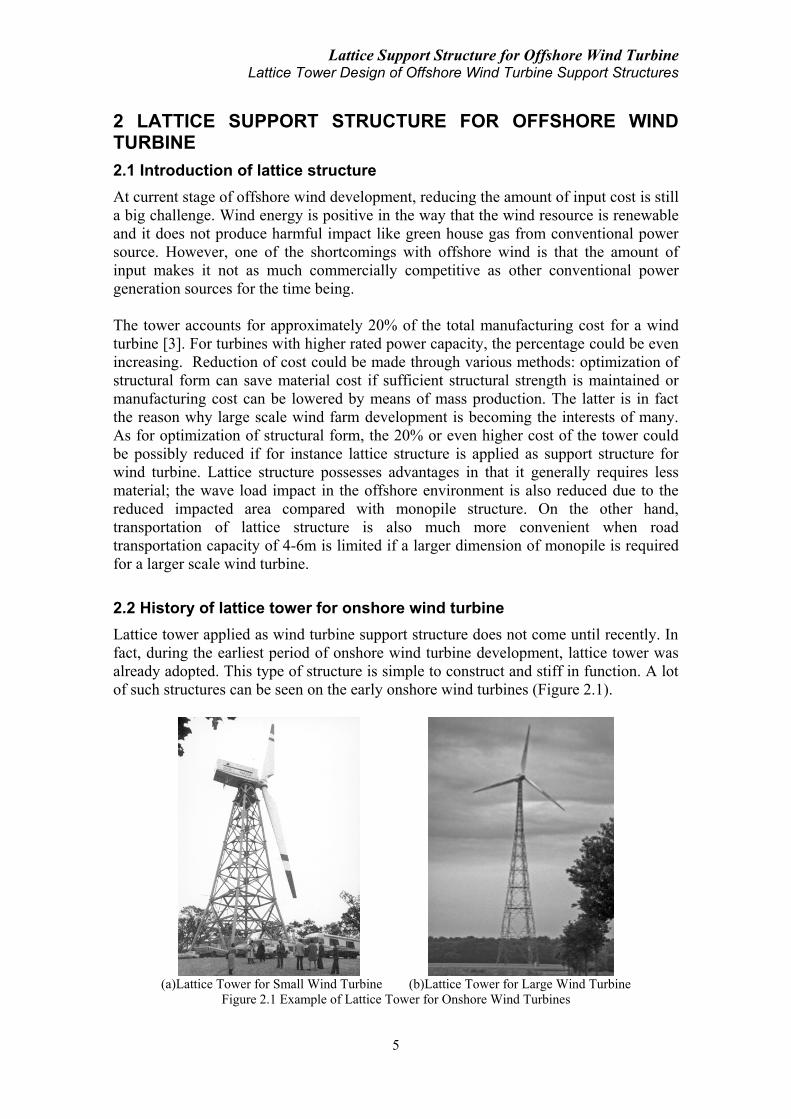
2.2 History of lattice tower for onshore wind turbine
Lattice tower applied as wind turbine support structure does not come until recently. In
fact, during the earliest period of onshore wind turbine development, lattice tower was
already adopted. This type of structure is simple to construct and stiff in function. A lot
of such structures can be seen on the early onshore wind turbines (Figure 2.1).
(a)Lattice Tower for Small Wind Turbine (b)Lattice Tower for Large Wind Turbine
Figure 2.1 Example of Lattice Tower for Onshore Wind Turbines

Lattice Support Structure for Offshore Wind Turbine Lattice Tower Design of Offshore Wind Turbine Support Structures
6
As the size of wind turbine increased, lattice tower was gradually displaced by tubular
tower. In the early experimental stage of wind energy and especially when the size of
wind turbine was still moderate, the emphasis was not placed on cost reduction of the
tower, which is why the tubular tower was very widely and popularly used. However, as
commercialization of wind energy is urged and the size of wind turbine grows, after
cost reduction measurements on mechanical components like the gearbox and generator
are achieved, cost minimization associated with the turbine support structure is again
attracting interests and this is why these years the lattice structure is receiving more and
more attentions, especially on large scale offshore wind turbines.
2.3 Current application of lattice support structure for offshore wind turbine
Going offshore, there is an even more urgent demand for cost reduction compared with
onshore situation. If onshore lattice tower was abandoned because of a particular
preference on aesthetics, the offshore sees no such problem since offshore wind turbine
is located at a distance from the coast, far from public eyes. Using lattice structure in
offshore has also a positive effect when considering the wave and current load on the
structure because the flow impacting area on a lattice structure is much smaller than that
on a tubular structure. Another big advantage for the lattice support structure is the
significant reduction of material cost compared with the tubular structure. With a given
height and stiffness, the expenditure of material for a lattice support structure is less
than the case of tubular tower by up to 40% [4]. This therefore results in a very
considerable cost advantage.
For current applications, hybrid concept composed of a lattice structure at the lower part
and a tubular tower structure at the upper part already exists for many projects (Figure
2.2). The application of such concept is usually in deep water depth ranging from 20m
to 50m. A full lattice support structure design for offshore wind turbine in deep water
region is yet found in practice. The following paragraphs introduce several projects of
hybrid design existing in sea:
Figure 2.2 Hybrid Support Structure for Offshore Wind Turbine [5]
2.3.1 OWEC jacket quattropod for Beatrice demo wind farm [6]
This demo project is composed of two 5MW wind turbines installed adjacent to the
Beatrice oil field, 25 km off the east coast of Scotland. The two units are located in

Lattice Support Structure for Offshore Wind Turbine Lattice Tower Design of Offshore Wind Turbine Support Structures
7
water depth up to 45m and each has a turbine weighing about 410 tons, fitted with three
blades each 63m long. The turbine is mounted on a tall tower which then sits above a
substructure fixed to sea bed. Hub height of the wind turbine is about 88m above sea
surface.
For the substructure supporting the tower, which is a tapered steel monopile weighing
about 210 tons, there are two design concepts. One of the designs is the OWEC Jacket
Quattropod (OJQ) (Figure 2.3(a)) which weighs about 750 tons plus the piling
arrangements. This design meets the required stiffness and fatigue life. The square base
of the OJQ has sides 20m long, thus covering about 400m2 of seabed. There is an
alternative tripod structure concept which has a slightly larger base area (about 600m2).
Both types of substructure can be fixed to the seabed either by suction piles or by driven
steel piles.
(a)OJQ for Beatrice Wind Farm (b)OJQ for Alpha Ventus Wind Farm
Figure 2.3 OWEC Jacket Quattropod on Offshore Wind Turbine [5]
2.3.2 OWEC jacket quattropod for Alpha Ventus offshore wind farm [7]
This wind farm is situated about 45 km north of the island of Borkum, Germany, in
water depth of 30 meters. The wind farm is composed of 12 wind turbines acting as the
first offshore wind farm for Germany. 6 of these 12 wind turbines employ the OWEC
Jacket Quattropod as substructure supporting the tower and the above turbine (Figure
2.3(b)). Each of the OJQ wind turbine is designed for a 5MW turbine. Weight of the
nacelle with rotor and hub is about 410 tons and the OJQ weighs about 500 tons (Table
2.1) while the tower above it weighs about 210 tons. The jacket structure has a height of
56 meters.
Table 2.1 Weight Break-down for OJQ Jacket at Alpha Ventus Project [8]
Jacket Frame (Legs & Bracings)
Primary Structure:
∑=425tons Jacket
Subtotal:
∑=510tons Total Weight per
Installation
∑=825tons
Pile Sleeves
Transition Piece including
Platform
Boat Landings (2 units) Secondary
Structure:
∑=85tons
Miscellaneous (e.g. J-tubes)
Anodes
Piles
315tons
(8 piles, D=1067mm, L=50m,
t=30mm)

Lattice Support Structure for Offshore Wind Turbine Lattice Tower Design of Offshore Wind Turbine Support Structures
8
2.3.3 RAMBØLL jacket for the Upwind project [9]
In this project, the jacket support structure is designed for a 5MW baseline turbine
(weighing about 350 tons including nacelle and rotor) in 50m water depth. The four
legged jacket has four levels of X-braces and four central piles with a penetration depth
of 48m grouted to the jacket legs. The total height of the jacket from mud line including
the transition piece and excluding the tower is 70.15m. The upper conical tower has a
total height of 68m resulting in a hub height of 90.55m above the mean sea surface. The
bottom tower section has a diameter of 5.6m. The complete support structure
configuration is shown in Figure 2.4. Design parameters of this jacket substructure
concept are shown in Table 2.2.
Figure 2.4 RAMBØLL Jacket Substructure Configuration for Upwind Project [9]
Table 2.2 Design Parameters of RAMBØLL Jacket Substructure for Upwind Project [9]
Base Width Pile Diameter Pile Penetration Jacket Weight All 4 Piles
Total Jacket Weight
(incl. Piles) Bottom Top
12m 8m 2082mm 48m 545tons 438tons 983tons
2.3.4 RAMBØLL jacket for the OC4 project [10]
In this design, the substructure is similar to the RAMBØLL design concept described
above for the Upwind project. Properties of the tubular members for the jacket
substructure are shown in Table 2.3. The height of this jacket substructure ranges from
water depth -45m to 20.15m above mean sea level. The base area is 12m×12m and the
jacket top area is 8m×8m.
Table 2.3 Properties of Jacket Members for OC4 Project [10]
Component Outer Diameter
(m)
Thickness
(mm)
X- and Mud Braces 0.8 20
Leg at Lowest Level 1.2 50
Leg at 2nd to 4th Level 1.2 35
Leg Crossing Transition Piece 1.2 40
Pile 2.082 60
2.3.5 REpower jacket [11]
WeserWind Offshore Construction Georgsmarienhütte in 2008 built a jacket
substructure for offshore wind turbine for the purpose of testing on land (Figure 2.5). A
REpower 5MW offshore turbine was installed on this jacket structure. The jacket
structure is approximately 57 meters in height and has a total weight of around 320 tons.
Standard steel pipes from the pipeline construction industry are used for the jacket. The
base of the foundation has a total area of nearly 300 m2 with the width of 17 meters.

Lattice Support Structure for Offshore Wind Turbine Lattice Tower Design of Offshore Wind Turbine Support Structures
9
Figure 2.5 REpower 5MW Wind Turbine on a Jacket Substructure [11]
2.4 Summary of lattice as support structure for offshore wind turbine
While lattice tower used for onshore wind turbine has a long history, though it was
replaced later by monotower, the application of lattice as support structure for offshore
wind turbine has started recently. Current applications of such lattice structure are
usually taking place in deep water depth of 30-50m, used as substructure supporting
monotower and designed for 5MW turbine weighing around 350-410 tons including
nacelle and rotor. The dimension of these lattice substructure designs vary from case to
case. While the OJQ design weighs around 510 tons (piles exclusive) supporting tower
of 210 tons and turbine of 410 tons, the RAMBØLL jacket concept weighs about 550
tons supporting turbine of 350 tons. In all of the previous designs, there is a critical
connection between the lattice substructure and the upper tower – the transition piece
(TP). The design of this transition piece has a significant variation ranging from a
concrete design (Upwind) to a steel design (Beatrice and Alpha Ventus) and from a
gravity base design to a steel conical design or even a steel bracing design. Detailed
introduction and these designs will be following.
Unlike for early onshore wind turbines where lattice structure is applied as full tower
(Figure 2.1), for offshore wind turbine the lattice structure is only used as a substructure
supporting the monotower above it (Figure 2.2). A full lattice design as support
structure for offshore wind turbine has yet been implemented. Application of such
concept will unavoidably induce another problem: the connection between the lattice
support structure and the turbine nacelle assembly, especially when aspects as the yaw
system, power transmission cable layout, etc are considered. The next chapter will
provide detailed description of this transition piece component including a case study of
lattice as full support structure proposed for a 5MW offshore wind turbine.
2.5 Introduction of transition piece
For the concept of a full lattice structure supporting offshore wind turbine, an important
issue is the appropriate connection of the lattice structure and the rotor nacelle assembly.
Early onshore wind turbine with turbine and rotor of small dimension has set up
previous experience, however, when the offshore wind farms go to regions of much
deeper water depth, the desired power capacity is becoming higher and higher and the
dimension as well as weight of the turbine nacelle assembly increases significantly
(Table 2.4), the role this transition piece plays will no doubt become a critical issue for

Lattice Support Structure for Offshore Wind Turbine Lattice Tower Design of Offshore Wind Turbine Support Structures
10
the design of the whole wind turbine unit. In March 2011, Vestas published its new
product of V164-7.0MW designed for offshore purpose [12]. The new turbine has a
rotor diameter of 164m and the weight of the rotor nacelle assembly reaches almost 500
tons. Under this industrial background with full of challenges, problems related to
transition piece connection with the yaw system, arrangement and layout of the power
transmission cables, ultimate and fatigue load transferring from the rotor nacelle
assembly to the support structure, etc all arise.
Table 2.4 Wind Turbine Size Trend
Year 1980 1985 1990 1995 2000 2005 2011 2015 2020
Rotor Diameter(m) 15 20 40 50 112 126 150 175 252-300
Rated Power(MW) <5.0 5.0 7.0-7.5 10 20
2.6 Transition piece for early onshore wind turbine supported by lattice tower
Early development of onshore wind turbines has set up experience of how to deal with
this transition piece. However, the dimension of the early turbines and their weight
cannot be compared with the multi megawatt requirement of present needs and even
larger turbine units in future, not to mention whether complex functional requirements
including the yaw control was taken into consideration or not in those early designs. A
frame-cylinder system composed of an external steel frame of supports and an internal
steel monocolumn in the core is adopted in the small wind turbine of Figure 2.1(a). A
single steel monocolumn structure sitting on top of the lattice support structure and
supporting the nacelle assembly is employed in the larger turbine of Figure 2.1(b).
These concepts are somehow early prototypes for the transition piece design of the more
recent hybrid offshore wind turbine support structures.
2.7 Transition piece for hybrid offshore wind turbine support structures
2.7.1 Transition piece for Beatrice demo wind farm
This design employs a frame-cylinder system (Figure 2.3(a)). The four legs of the
bracing sit on top of the four legs of the lattice substructure respectively and linearly
enlarge in diameter to connect with a cylinder structure inside the frame of bracings.
The four legs of this transition piece have uniform structural dimension but the diameter
of each leg varies from the connecting end with the lattice substructure leg to the other
end with the internal cylinder. At the connecting points with the lattice legs, the
diameter of the four bracing legs is at the same magnitude with the lattice legs. At the
other end, the diameter of the bracing legs is increased significantly by almost 2-3 times
which strengthens the connection with the cylinder structure in the core. There is a ring
plate sitting above the four connecting ends between the bracing legs and the cylinder.
On top of the cylinder a complex system exists which should be able to allow
convenient and robust connection between the upper tower and this transition piece. At
the surface right above the lattice substructure locates the platform of this offshore wind
turbine. According to M. Seidel [8], this design is relatively heavy but it enables a wide
jacket tip and flexible batter angels.

Lattice Support Structure for Offshore Wind Turbine Lattice Tower Design of Offshore Wind Turbine Support Structures
11
2.7.2 Transition piece for Alpha Ventus offshore wind farm
In the Alpha Ventus offshore wind farm, the same jacket substructure design OJQ is
used on half of the total number of wind turbines. The transition piece design is
however altered from its older brother for the Beatrice wind farm.
In this more recent design (Figure 2.3(b)), the transition piece is designed obviously
lighter than the previous design for the Beatrice wind farm. The structural form stays
the same, which consists of a steel cylinder in the core, four legs of bracing connecting
the lattice legs and the internal cylinder, a ring plate sitting on top of the upper bracing
leg joints and other miscellaneous components. Compared with the Beatrice design, the
dimension of the bracing legs and the core cylinder are all reduced. Diameter of each
bracing leg still shows variation from the lower connection joint to the upper one, but
the degree of this variation is shrunk much more than the previous design resulting in a
more or less uniform diameter that is nearly the same as that of the lattice substructure
legs. Geometric comparison between this Alpha Ventus design and the previous
Beatrice design shows a trend of lighter design and hence lower material cost. Reasons
for this design alternation could include the different load conditions in each specific
site Nevertheless, the lattice substructure design is generally the same and the installed
turbine units in these two projects are also the same (REpower 5MW). An improvement
made after the experience from the older brother design could be another reason for the
alternation in this more recent design.
2.7.3 Transition piece for the Upwind and OC4 project
By the time of this thesis work, the RAMBØLL jacket concept has not been put into
practice yet. In this design concept, however, RAMBØLL proposes a different
configuration of lattice substructure from the OJQ design, i.e., the bottom width of
RAMBØLL jacket is designed as 12m whereas the OJQ has a bottom width of around
20m. The transition piece employed here is also significantly different, being a rigid
massive concrete block weighing 666 tons with a dimension of 4m×9.6m×9.6m (Figure
2.4). Connection with the lattice substructure is made via grouting of the upper part of
the four lattice legs into the concrete block.
The material for the transition piece has been chosen as reinforced concrete rather than
the other steel concept, which is based on a cost benefit evaluation. The concrete
transition piece has the weight as a disadvantage. However, it is neither as susceptible to
fatigue damage nor as labour intensive compared to a steel transition piece [9].
2.7.4 Transition piece for REpower jacket in Bremerhaven
For this solution developed by REpower (Figure 2.6), the structure is lighter compared
with the first OJQ Beatrice transition piece. The structure has a truncated cone shape
with four external struts connected to the cone surface. These four struts sit on the four
jacket legs respectively and extend upwards before the flange connection with the upper
tower. The height of the steel cone is about 7 meters and the structure weighs about 50
tons. The structure has so far only been tested for a relatively steep batter angle and a
narrow jacket top [8].

Lattice Support Structure for Offshore Wind Turbine Lattice Tower Design of Offshore Wind Turbine Support Structures
12
Figure 2.6 Transition Piece of REpower Jacket [8]
2.8 Summary of transition piece designs
Although designs of the transition piece vary according to specific and individual
project requirements including the loading condition, connecting structural dimension,
the rotor nacelle assembly weight, etc, there are some general types of the transition
piece design for selection and consideration:
(1) Frame-cylinder. This design is composed of a steel frame of bracings in the outside
and a steel cylinder structure in the core. Both early onshore lattice tower supported
wind turbine (Figure 2.1(a)) and recent hybrid offshore wind turbine (Figure 2.3) have
applied this design concept. From a structural characteristics point of view, this
combination of an external frame system and an internal cylinder structure will increase
the strength and the robustness of the transition piece. The bracing legs are designed to
allow for convenient connection with the lattice substructure and the internal cylinder
structure is employed for connection with the upper tower, through the application of a
specific flange connection. The more recent design of such a transition piece concept for
the OJQ in Alpha Ventus project (Figure 2.3(b)) has a shrunk design and reduced
weight than the earlier design for the same OJQ in Beatrice wind farm (Figure 2.3(a)).
(2) Steel Cone. This design has a simpler geometry profile compared with the previous
frame-cylinder structure. Reduction of material cost might be achieved through the
elimination of the bracing legs but the larger dimension of the cone structure will in the
same time require a higher demand of material cost. Connection with the lattice legs
requires the addition of a number of struts (Figure 2.6). This type of transition piece has
only been tested for the REpower jacket on land. For onshore wind turbine a cylinder
structure with uniform diameter rather than the truncated cone shaped can be found
(Figure 2.1(b)).
(3) Concrete block. This design has only been proposed in the research stage and not
been seen in real practice yet. The advantage of such a design is its cost benefit. A
heavy concrete block weighing several hundred tons will have a big influence on the
dynamic behavior of the whole support structure system. The decision to adopt this
heavy transition piece design concept should be specifically made in combination with
the analysis of support structure’s dynamic properties.
All the above design concepts are either actually employed or only studied for onshore
lattice tower supported wind turbines and hybrid offshore wind turbines. Since there is
no existing experience of a full lattice structure supported offshore wind turbine, there is
Lattice Support Structure for Offshore Wind Turbine Lattice Tower Design of Offshore Wind Turbine Support Structures
13
no design prototype to learn from for a transition piece design between a full lattice
support structure and directly the turbine nacelle assembly. However, the previously
introduced concepts of the frame-cylinder structure and the steel cone structure could be
possibly applied as connection for the lattice support structure and the nacelle assembly
due to the light weight characteristic. The heavy design like the concrete block might be
possible for the hybrid support structure concept but should be avoided for a full lattice
supported offshore wind turbine because an addition of this heavy component from the
transition piece which is almost at the same or even bigger magnitude of the rotor
nacelle assembly weight will force the support structure to bear an extremely large mass
of over twice as much as a normal turbine nacelle assembly at the structure top. An
inclination of the structural vertical axis will thus induce a significantly larger bending
moment at the base of the support structure as well as a much larger deflection of the
structure itself. Detailed analysis of the previously mentioned design concepts will be
introduced in the following chapters.

Lattice Support Structure for Offshore Wind Turbine Lattice Tower Design of Offshore Wind Turbine Support Structures
14
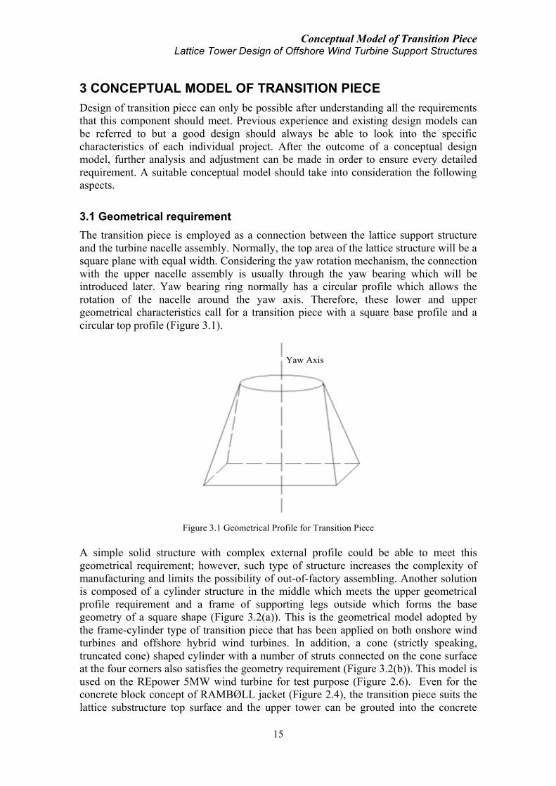
Conceptual Model of Transition Piece Lattice Tower Design of Offshore Wind Turbine Support Structures
15
3 CONCEPTUAL MODEL OF TRANSITION PIECE
Design of transition piece can only be possible after understanding all the requirements
that this component should meet. Previous experience and existing design models can
be referred to but a good design should always be able to look into the specific
characteristics of each individual project. After the outcome of a conceptual design
model, further analysis and adjustment can be made in order to ensure every detailed
requirement. A suitable conceptual model should take into consideration the following
aspects.
3.1 Geometrical requirement
The transition piece is employed as a connection between the lattice support structure
and the turbine nacelle assembly. Normally, the top area of the lattice structure will be a
square plane with equal width. Considering the yaw rotation mechanism, the connection
with the upper nacelle assembly is usually through the yaw bearing which will be
introduced later. Yaw bearing ring normally has a circular profile which allows the
rotation of the nacelle around the yaw axis. Therefore, these lower and upper
geometrical characteristics call for a transition piece with a square base profile and a
circular top profile (Figure 3.1).
Figure 3.1 Geometrical Profile for Transition Piece
A simple solid structure with complex external profile could be able to meet this
geometrical requirement; however, such type of structure increases the complexity of
manufacturing and limits the possibility of out-of-factory assembling. Another solution
is composed of a cylinder structure in the middle which meets the upper geometrical
profile requirement and a frame of supporting legs outside which forms the base
geometry of a square shape (Figure 3.2(a)). This is the geometrical model adopted by
the frame-cylinder type of transition piece that has been applied on both onshore wind
turbines and offshore hybrid wind turbines. In addition, a cone (strictly speaking,
truncated cone) shaped cylinder with a number of struts connected on the cone surface
at the four corners also satisfies the geometry requirement (Figure 3.2(b)). This model is
used on the REpower 5MW wind turbine for test purpose (Figure 2.6). Even for the
concrete block concept of RAMBØLL jacket (Figure 2.4), the transition piece suits the
lattice substructure top surface and the upper tower can be grouted into the concrete
Yaw Axis

Conceptual Model of Transition Piece Lattice Tower Design of Offshore Wind Turbine Support Structures
16
block. Various structural profiles which can meet the above mentioned geometry
characteristics suffice but for simplicity, with consideration of manufacturing,
transportation, assembly and structural cost, the existing frame-cylinder concept and the
cone-strut concept seem to have more advantages than the others.
(a)Frame-cylinder (b)Cone-strut
Figure 3.2 Various Geometrical Models for Transition Piece
3.2 Functional requirement
In addition to the geometrical challenge, the transition piece should also be able to meet
a number of functional requirements. Transition piece is a critical design component
which needs careful detailing. Several authors have previously shown lattice support
structure design proposals, but this transition structure was often only sketched and not
realistically designed. There is a large uncertainty for those proposals because the
transition piece is the greatest design challenge (M. Seidal [8]). Functional requirement
need to be observed regarding the following aspects:
3.2.1 Power transmission equipment
For conventional monotower support structure, all the electrical equipment including
power transmission cable, switchgear and even the transformer can be located inside the
support structure (Figure 3.3). For a lattice support structure, location of large size
equipment can be a challenge because there is no external coverage for protection of the
equipment. This problem appears especially in the harsh offshore environment where
corrosion and other environmental eroding sources are present. Particularly, for the power transmission cable, one of the challenges is the twisting of
the cables (e.g. the cable loop for twisting in Figure 3.3). For offshore wind turbine, an
additional consideration of lay out of the cables in the sea water is required. When the
lattice structure is applied as support structure, the challenge of cable arrangement is no
doubt increased. Current solution for protection of power transmission cables in
offshore employs external equipment like the J-tube (Figure 3.4). The J-tubes provide
solution for cable placement in the sea water, however, these additional equipment also
add cost to the amount of input. Elimination of the J-tube will reduce the cost, if
alternative solutions for cable placement are possible. For lattice support structure, since
the diameter of the lattice leg of existing designs is usually around 1.0m, there is thus a
requirement on the maximum diameter of the power transmission cable to be used if the
solution can be made by means of locating the power transmission cable inside one of
the four lattice legs. Alternatively, if there are a multiple number of cables transmitting
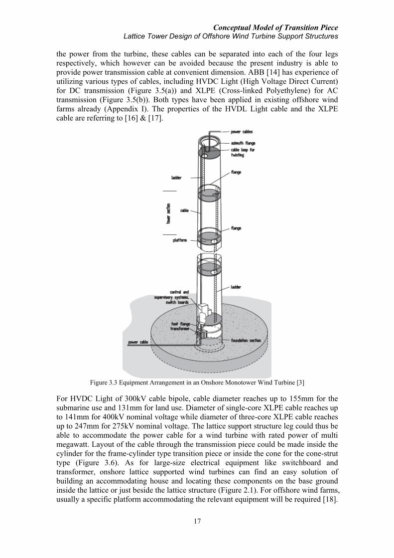
Conceptual Model of Transition Piece Lattice Tower Design of Offshore Wind Turbine Support Structures
17
the power from the turbine, these cables can be separated into each of the four legs
respectively, which however can be avoided because the present industry is able to
provide power transmission cable at convenient dimension. ABB [14] has experience of
utilizing various types of cables, including HVDC Light (High Voltage Direct Current)
for DC transmission (Figure 3.5(a)) and XLPE (Cross-linked Polyethylene) for AC
transmission (Figure 3.5(b)). Both types have been applied in existing offshore wind
farms already (Appendix I). The properties of the HVDL Light cable and the XLPE
cable are referring to [16] & [17].
Figure 3.3 Equipment Arrangement in an Onshore Monotower Wind Turbine [3]
For HVDC Light of 300kV cable bipole, cable diameter reaches up to 155mm for the
submarine use and 131mm for land use. Diameter of single-core XLPE cable reaches up
to 141mm for 400kV nominal voltage while diameter of three-core XLPE cable reaches
up to 247mm for 275kV nominal voltage. The lattice support structure leg could thus be
able to accommodate the power cable for a wind turbine with rated power of multi
megawatt. Layout of the cable through the transmission piece could be made inside the
cylinder for the frame-cylinder type transition piece or inside the cone for the cone-strut
type (Figure 3.6). As for large-size electrical equipment like switchboard and
transformer, onshore lattice supported wind turbines can find an easy solution of
building an accommodating house and locating these components on the base ground
inside the lattice or just beside the lattice structure (Figure 2.1). For offshore wind farms,
usually a specific platform accommodating the relevant equipment will be required [18].
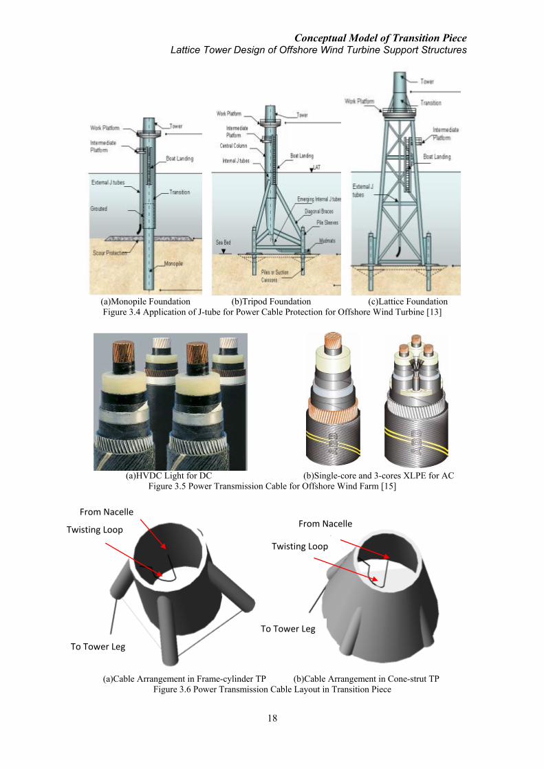
Conceptual Model of Transition Piece Lattice Tower Design of Offshore Wind Turbine Support Structures
18
(a)Monopile Foundation (b)Tripod Foundation (c)Lattice Foundation
Figure 3.4 Application of J-tube for Power Cable Protection for Offshore Wind Turbine [13]
(a)HVDC Light for DC (b)Single-core and 3-cores XLPE for AC
Figure 3.5 Power Transmission Cable for Offshore Wind Farm [15]
(a)Cable Arrangement in Frame-cylinder TP (b)Cable Arrangement in Cone-strut TP
Figure 3.6 Power Transmission Cable Layout in Transition Piece
From Nacelle
To Tower Leg
Twisting Loop From Nacelle
Twisting Loop
To Tower Leg

Conceptual Model of Transition Piece Lattice Tower Design of Offshore Wind Turbine Support Structures
19
3.2.2 Yaw system
If the rotor is to fully capture the power from wind, it should be oriented correctly with
respect to the incoming wind direction. A yaw angle, i. e. an angle deviation between
rotor axis and mean wind direction, causes a loss of power production. In general the
rotor can be oriented into the wind by three types of yawing concepts (Figure 3.7):
(1) Aerodynamic yawing via wind vanes or fan-tail wheels;
(2) Free yawing of downwind rotor;
(3) Active yawing by motorized yaw drive.
(a)Aerodynamic Yawing (b)Passive/Free Yawing (c)Active/Motorized Yawing
Figure 3.7 Different Yawing Concepts [19]
The first concept is not found in present large turbines any more. For modern wind
turbines of multi-megawatt rated power with rotor nacelle assembly mass of over 300
tons and rotor diameter of over 120m, this yawing method is far outdated. As for the
idea to exploit free yawing of a downwind rotor, if this is successful, manufacturing
cost can be saved. However, attempts to introduce free yawing to large turbines have
not been successful so far. Motorized yawing had not been intended originally but
initial tests with the prototype showed that correct and stable free yawing of the rotor
was not possible so that a motorized yaw drive had to be subsequently installed.
Extensive test programs were carried out on the experimental American MOD-0 turbine
to investigate free rotor yawing [20] and these tests confirmed that accurate free yawing
could not to be achieved. The presently exclusively employed motorized yaw system or
active yaw system has the task of automatically orienting the rotor and the nacelle into
the wind. Some of the components of this active yaw system are integrated into the
nacelle and some should be connected with the transition piece. The entire system
consists of the following components:
Yaw bearing
Yaw bearing is subject to contradictory requirements. On one hand it should ensure
easy-running yawing and a long service life and on the other hand yaw damping is
desirable, even during the yawing, in order to avoid unwanted yawing oscillation. These
requirements can be met both by a conventional roller bearing and by a gliding bearing.
The traditional design consists of a large roller bearing whereas a four-point ball bearing
is used often in more recent designs. The alternative is a gliding bearing in which the
nacelle moves on sliding elements made of synthetic material. One advantage of the
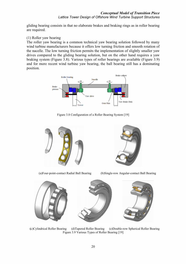
Conceptual Model of Transition Piece Lattice Tower Design of Offshore Wind Turbine Support Structures
20
gliding bearing consists in that no elaborate brakes and braking rings as in roller bearing
are required.
(1) Roller yaw bearing
The roller yaw bearing is a common technical yaw bearing solution followed by many
wind turbine manufacturers because it offers low turning friction and smooth rotation of
the nacelle. The low turning friction permits the implementation of slightly smaller yaw
drives compared to the gliding bearing solution, but on the other hand requires a yaw
braking system (Figure 3.8). Various types of roller bearings are available (Figure 3.9)
and for more recent wind turbine yaw bearing, the ball bearing still has a dominating
position.
Figure 3.8 Configuration of a Roller Bearing System [19]
(a)Four-point-contact Radial Ball Bearing (b)Single-row Angular-contact Ball Bearing
(c)Cylindrical Roller Bearing (d)Tapered Roller Bearing (e)Double-row Spherical Roller Bearing
Figure 3.9 Various Types of Roller Bearing [19]

Conceptual Model of Transition Piece Lattice Tower Design of Offshore Wind Turbine Support Structures
21
(2) Gliding yaw bearing
The gliding yaw bearing is a combined axial and radial bearing. The modern yaw
bearings can restrain the nacelle from being rotated by the moments induced by the
upper half of the rotor sweep disk and the torque of the drive train. Principally, the
simplest way to accomplish the yaw bearing task with gliding elements is with two
gliding planes for the axial loads (top and bottom) and a radial gliding surface for the
radial loads. Consequently, the gliding yaw bearing comprises three surfaces covered
with multiple gliding pads. These gliding pads come in sliding contact with a steel disk,
which is usually equipped with gear teeth to form a gliding-disk/gear-rim (Figure 3.10).
Figure 3.10 Configuration of Gliding Bearing System [19]
(3) Comparison of yaw bearings
For the purpose of designing an optimal transition piece, it is essential to study the
differences of various types of yaw bearings so as to understand the pros and cons of
each type for the selection for a multi megawatt offshore wind turbine. Generally,
selection of the yaw bearing type should include considerations of the loads, the yawing
rate, required life time and available space within the nacelle assembly. Differences
between the roller yaw bearing and the gliding yaw bearing are shown below in Table
3.1.
Table 3.1 Comparison of Different Types of Yaw Bearings
Category Roller Gliding Segmentation Non-segmented Segmented or Non-segmented
Friction Small Normal
Yaw Drive Small Normal
Elaborate Bracking Needed Not necessary
Lubrication Central lubrication or
Self lubricated elements
Repair Disassembly needed
Reparability via individual segment for
segmented system; External crane or
mechanical or hydraulic jack needed for
non-segmented system
Products REpower 5M (4-point ball bearing)
REpower 6M (4-point ball bearing)
Vestas V90-3.0MW (Friction gliding
bearing)
As previously mentioned, for present large size wind turbines, roller bearing especially
the four-point ball bearing is widely used. The gliding bearing on the other hand has
successful applications on small size and medium size (Vestas V90-3MW) turbines.
Yaw drive
The two choices for the yaw drive are hydraulic and electrical components. Promoters
of the hydraulic system name lower cost, smaller size and also higher torque as

Conceptual Model of Transition Piece Lattice Tower Design of Offshore Wind Turbine Support Structures
22
advantages. Another advantage of hydraulic yaw drive is that it is easy to control
compared with electric drive. The power of the drive motor depends on the rate of
adjustment required. Electric motor is being increasingly used in more recent yaw
drives. The hydraulic drive is being replaced by the controllable electric drive motor.
Some manufacturers are using electric yaw drive with integrated brakes so that separate
yaw brakes are no longer required.
The number of the yaw drives and their location with regards to the yaw bearing vary
from design to design. The yaw drives may be located at the outer surface of the yaw
bearing ring (Figure 3.11) or they may be located at the inner surface of the yaw bearing
ring (Figure 3.8 & Figure 3.10). The REpower 5MW wind turbine, for instance, has
yaw drives connecting with the outer surface of the yaw bearing ring.
Figure 3.11 Location of Yaw Drive in REpower 5MW Turbine System
Yaw brakes
In order to avoid the drive motors from having to absorb the yawing moment after a
completed yawing operation, a yaw brake is required unless special electrical yaw
drives with integrated braking function are used.
Locking system
In larger turbines, the yaw drive is positively locked in position for extended standstill
period, for example for maintenance. This job is handled by one or several locking bolts.
Yaw control system
Yawing the nacelle into the wind direction requires a special control and operating logic.
The yaw control mechanism is basically a function of the yaw angle. For instance, the
wind measuring system of the turbine provides a mean value of the wind direction over
a period of ten seconds. This value is compared with the instantaneous position of the
rotor axis every two seconds. If the deviation remains below 3 degrees, the yaw control
system will not be activated. If the yaw angle is small, for example 10 degrees, yawing
is carried out within 60 seconds, if it is greater, e.g. 20 degrees, the yaw is accomplished
within the subsequent 20 seconds. If the yaw angle determined exceeds a value of 50
degrees, the rotor is yawed immediately. On the other hand, yawing starts at rotor
standstill at a low wind speed, e. g. 1 m/s below cut-in speed. If the wind speed exceeds
cut-out value, the rotor will not be yawed. If extreme yaw angles occur at the non-
rotating turbine with such extreme wind speed, the yaw brakes can slip so that the
aerodynamic forces can passively yaw the leeward rotor, which provides a protection
for the yaw system under extreme wind speed in combination with extreme yaw angle
[21]. Apart from trying to keep the mean yaw angle as small as possible, the yawing

Conceptual Model of Transition Piece Lattice Tower Design of Offshore Wind Turbine Support Structures
23
rate of the rotor is also determined by taking into consideration the rotational moments.
The yawing rate is normally about 0.3-0.5 º/s. Failure statistics of wind turbines display
a conspicuous accumulation in the “yaw system” component. It is, therefore, absolutely
imperative that the dynamic load situation and the vibrational behaviour of the yaw
drive be analyzed.
3.3 Mechanical requirement
3.3.1 Connection with the lattice support structure
Connection between the lower lattice support structure and the transition piece can
normally be made through the welding of the lattice legs and the respective bracing legs
of the frame-cylinder system or the external struts of the cone-strut system. Welding
should ensure a sufficient strength which is able to transfer the loads from the rotor and
nacelle to the lattice support structure. On the other hand, sufficient fatigue strength of
the connections is also a big challenge. As for previously introduced hybrid design of
OWEC jacket transition piece (Figure 2.3), a plane plate is employed covering the
lattice top and can also be used as the service platform. The transition piece connecting
the full lattice support structure and the turbine nacelle will however not necessarily
require this plane plate acting as the service platform. However, the placement of a
plane plate on top of lattice support structure will be able to connect the structural
components of the lattice top bracings and the four legs, which helps increasing the
plane stiffness of the whole support structure. Furthermore, this plane plate also
provides foundation for the sitting of the cylinder and cone base for both types of the
transition piece.
3.3.2 Connection with the nacelle assembly
Connection between the transition piece and the upper turbine nacelle assembly is
usually made through the connection of the yaw bearing ring and the cylinder
component of the transition piece (Figure 3.12). This connection method firstly requires
a match of the geometrical dimension of the transition piece cylinder and that of the
yaw bearing outer ring. Connection of these two components is usually made by means
of bolting (Figure 3.13).
(a)Transition Piece (Frame-cylinder) Connection with Yaw Bearing Ring
Nacelle Bedplate
Transition Piece
Lattice Leg
Yaw Connection Ring
Transition Piece
Extension into Nacelle

Conceptual Model of Transition Piece Lattice Tower Design of Offshore Wind Turbine Support Structures
24
(b)Transition Piece (Cone-strut) Connection with Yaw Bearing Ring
Figure 3.12 Transition Piece Connection with Yaw Bearing inside the Nacelle Assembly
Figure 3.13 Bolting Connection of Yaw Bearing and Cylinder Flange [22]
The bolting should ensure a sufficient level of strength due to the existence of the highly
complex loading conditions to be transferred at this crucial conjunction. An inner flange
in the transition piece cylinder might be needed for the convenience of sufficient
connection with the yaw bearing ring. No matter what type of transition piece concept is
to be applied, an extension of the cylinder core or the upper part of the cone concept
should be designed in order to allow for connection with the yaw bearing inside the
nacelle’s protection. In offshore environment, exposure of the yaw bearing outside the
turbine nacelle will no doubt increase the probability of damage due to the harsh
environmental eroding factors present.
3.4 Mechanical model of transition piece
Based on previous description of conceptual design requirements for the transition piece
in terms of the geometry, power utilities layout and especially the yaw bearing
connection aspects, mechanical model of the transition piece can be simplified as
following for engineering modeling and structural analysis.
Nacelle Bedplate
Transition Piece
Lattice Leg
Yaw Connection Ring
Transition Piece
Extension into Nacelle

Conceptual Model of Transition Piece Lattice Tower Design of Offshore Wind Turbine Support Structures
25
3.4.1 Boundary condition
The lower boundary condition of the transition piece is basically depending on the
structural characteristics of the lattice support structure. A spring system of three
degrees of freedom should be sufficient to satisfy the need:
(1) Fixed constraint in the Z direction (vertical, Figure 3.14) due to connection with the
lattice support structure and a spring system in the X and Y direction (horizontal)
concerning the bending stiffness of the lattice support structure in the respective
direction. The spring coefficients are thus KX & KY which are based on the static
bending stiffness of the lattice support structure.
(2) A torsional spring system depending on the torsional stiffness of the support
structure in the X-O-Y plane. The spring coefficient is thus Kt which is the static
torsional stiffness of the lattice support structure.
Figure 3.14 Boundary Condition of Transition Piece Using Spring System
3.4.2 Analysis of a full lattice support structure concept
In order to provide reliable parameters to serve as boundary condition for the transition
piece, proposal of a full lattice structure acting as support structure (including tower and
substructure) for a reference offshore wind turbine is made. Due to the absence of
design experience in this field, the design here will be partly based on previous hybrid
concepts introduced in Chapter 2. Physical properties of such a design including the
total mass distribution, overall dimension, structural member parameters, etc are given.
Modal analysis regarding the structural dynamic characteristics is also performed.
Detailed load analysis of such a structure is however not the main focus of this thesis.
Linear bending and torsional stiffness will be finally provided to give basis on
assessment of the structural strength and also to provide parameters for transition piece
boundary.
Design requirement
The background of this lattice support structure design is at water depth of 30m
supporting a 5MW reference wind turbine (Table 3.2). Hub height of this offshore wind
turbine is set at 90m which makes the total height of the lattice structure 120m. Total
mass of the nacelle and rotor (rotor nacelle assembly, RNA) is 350 tons.
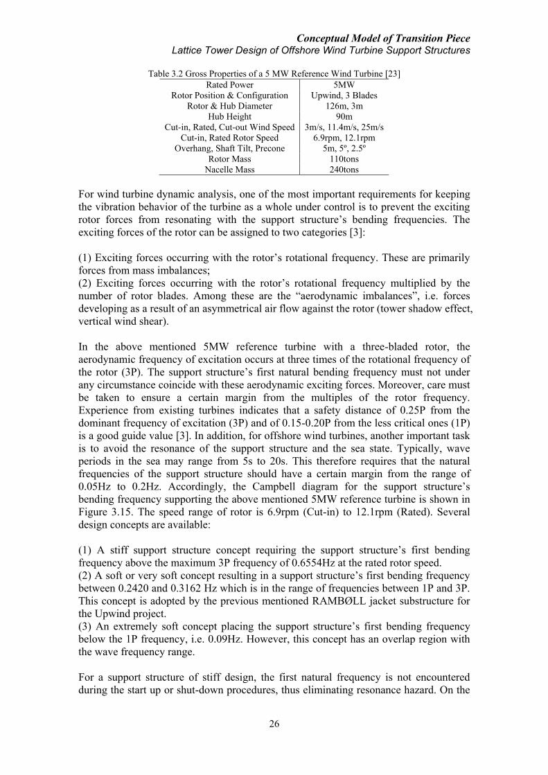
Conceptual Model of Transition Piece Lattice Tower Design of Offshore Wind Turbine Support Structures
26
Table 3.2 Gross Properties of a 5 MW Reference Wind Turbine [23]
Rated Power 5MW
Rotor Position & Configuration Upwind, 3 Blades
Rotor & Hub Diameter 126m, 3m
Hub Height 90m
Cut-in, Rated, Cut-out Wind Speed 3m/s, 11.4m/s, 25m/s
Cut-in, Rated Rotor Speed 6.9rpm, 12.1rpm
Overhang, Shaft Tilt, Precone 5m, 5º, 2.5º
Rotor Mass 110tons
Nacelle Mass 240tons
For wind turbine dynamic analysis, one of the most important requirements for keeping
the vibration behavior of the turbine as a whole under control is to prevent the exciting
rotor forces from resonating with the support structure’s bending frequencies. The
exciting forces of the rotor can be assigned to two categories [3]:
(1) Exciting forces occurring with the rotor’s rotational frequency. These are primarily
forces from mass imbalances;
(2) Exciting forces occurring with the rotor’s rotational frequency multiplied by the
number of rotor blades. Among these are the “aerodynamic imbalances”, i.e. forces
developing as a result of an asymmetrical air flow against the rotor (tower shadow effect,
vertical wind shear).
In the above mentioned 5MW reference turbine with a three-bladed rotor, the
aerodynamic frequency of excitation occurs at three times of the rotational frequency of
the rotor (3P). The support structure’s first natural bending frequency must not under
any circumstance coincide with these aerodynamic exciting forces. Moreover, care must
be taken to ensure a certain margin from the multiples of the rotor frequency.
Experience from existing turbines indicates that a safety distance of 0.25P from the
dominant frequency of excitation (3P) and of 0.15-0.20P from the less critical ones (1P)
is a good guide value [3]. In addition, for offshore wind turbines, another important task
is to avoid the resonance of the support structure and the sea state. Typically, wave
periods in the sea may range from 5s to 20s. This therefore requires that the natural
frequencies of the support structure should have a certain margin from the range of
0.05Hz to 0.2Hz. Accordingly, the Campbell diagram for the support structure’s
bending frequency supporting the above mentioned 5MW reference turbine is shown in
Figure 3.15. The speed range of rotor is 6.9rpm (Cut-in) to 12.1rpm (Rated). Several
design concepts are available:
(1) A stiff support structure concept requiring the support structure’s first bending
frequency above the maximum 3P frequency of 0.6554Hz at the rated rotor speed.
(2) A soft or very soft concept resulting in a support structure’s first bending frequency
between 0.2420 and 0.3162 Hz which is in the range of frequencies between 1P and 3P.
This concept is adopted by the previous mentioned RAMBØLL jacket substructure for
the Upwind project.
(3) An extremely soft concept placing the support structure’s first bending frequency
below the 1P frequency, i.e. 0.09Hz. However, this concept has an overlap region with
the wave frequency range.
For a support structure of stiff design, the first natural frequency is not encountered
during the start up or shut-down procedures, thus eliminating resonance hazard. On the

Conceptual Model of Transition Piece Lattice Tower Design of Offshore Wind Turbine Support Structures
27
other hand, this problem with a risk of resonance does exist in the soft, very soft or
extremely soft designs. In the course of wind turbine development, almost all
manufactures changed to increasingly more flexible designs, for reason of economy. For
the three-bladed rotor wind turbines, a soft design concept with the support structure’s
first natural bending frequency located between 1P and 3P is thus commonly adopted.
However, if a lattice structure is used as support structure for offshore wind turbine, due
to the already mentioned cost-effective aspect of such a structure, even a stiff concept of
support structure design could still be advantageous with regards to the material saved,
compared with a conventional monotower support structure.
Figure 3.15 Support Structure Bending Frequency Range
Geometry
Considering the simplicity for design and manufacturing, four legs and ten levels of X
bracings are suggested for the lattice structural design. Layout of the bracings is
regulated in a way that the angel between each bracing and the respective leg is kept
constant, leading to a constant K-joint angle for the whole structure. At the top of this
structure there are four horizontal bracings connecting the four legs; at the bottom four
mud bracings are placed connecting the four legs. The area at the top of the lattice
structure is designed as 4m×4m, with consideration of transition piece connection to the
turbine nacelle. Bottom width of this structure is a decisive factor for the stiffness and
natural frequencies of this structure. In order to achieve a proper final design, studies of
structural performance based on varying base width levels are performed in the
following section. Nevertheless, this structure has a linear straight line configuration
with the four legs tapered from bottom to top. The general configuration of this lattice
structure is shown in Figure 3.16.

Conceptual Model of Transition Piece Lattice Tower Design of Offshore Wind Turbine Support Structures
28
Figure 3.16 Configuration of a Lattice Support Structure for a 5MW Reference Offshore Wind Turbine
Numerical Modeling
By means of finite element analysis, numerical models of several different designs are
set up. These different designs mainly consider two control factors, i.e. the base width
and the structural member dimensions. Three levels of base width are studied and two
types of structural member dimensions are analyzed: namely, one heavy concept and the
other light concept. Steel is used as the material for the whole lattice structure. Material
properties including density, Young’s modulus, Poisson’s ratio and damping are shown
below. Comparison of these different design concepts is shown in Table 3.4. Eigen
modes of model 12L in Table 3.4 are illustrated in Appendix II.
Table 3.3 Material Properties for Lattice Support Structure
Density 7850 kg/m3
Young’s Modulus 2.1E+11 N/m2
Poisson ratio 0.3
Structural damping 1%
Selection of design model
Selection of a suitable design of lattice support structure for offshore wind turbine shall
take various factors into consideration:
(1) Cost
For the proposal of a full lattice support structure, cost efficient aspect has to be
maintained at the maximum effort since this is one of the greatest advantages for a
lattice structure design, providing it a bigger potential than the other structural types.
Water Depth

Conceptual Model of Transition Piece Lattice Tower Design of Offshore Wind Turbine Support Structures
29
Table 3.4 Comparison of Lattice Structural Properties Based on Varying Design Concepts
Structural Overall Height (m) 120
Base Area Width (m) 21 12 8
Top Area Width (m) 4 4 4
Median Overall Height/Width Ratio 9.6 15 20
Structural Member Dimension Concept H(1) L(2) H L H L
Model Index 21H 21L 12H 12L 8H 8L
Rotor Nacelle Assembly Weight (tons) 350 350 350 350 350 350
Estimated Transition Piece Weight(3) (tons) 50 50 50 50 50 50
Support Structure Weight (tons) 1075 523 1008 501 978 492
Linear Bending Stiffness (103 kN/m) 12.327 7.764 4.904 3.052 2.597 1.584
Linear Torsional Stiffness (105 kN∙m/rad) 39.448 7.955 18.716 4.294 10.563 2.729
1st fore-aft frequency (Hz) 0.7140 0.6250 0.4508 0.3913 0.3265 0.2807
1st side-side frequency (Hz) 0.7140 0.6250 0.4508 0.3913 0.3265 0.2807
2nd fore-aft frequency (Hz) 3.3938 >4 2.5595 2.4142 2.0470 1.9376
2nd side-side frequency (Hz) 3.3938 >4 2.5595 2.4142 2.0470 1.9376
3rd fore-aft frequency (Hz) >7 >4 5.9886 5.1185 5.0745 4.4936
3rd side-side frequency (Hz) >7 >4 5.9886 5.1185 5.0745 4.4936
1st torsional frequency (Hz) 4.0149 2.7172 2.9098 1.8590 2.1729 1.3575
2nd torsional frequency (Hz) 4.9086 2.9192 5.6359 2.3789 5.3357 2.3167
Note:
(1)The H (for “heavy”) design applies member dimensions according to the RAMBØLL jacket
substructure design, i.e. leg diameter 1.2m, leg thickness 0.04m; bracing diameter 0.8m, bracing thickness
0.02m.
(2)The L (for “light”) design is considered as reduced member dimensions, i.e. leg diameter 0.9m, leg
thickness 0.035m and bracing diameter 0.36m, bracing thickness 0.014m.
(3)The design of the transition piece is a decisive factor for the vibrational behavior of the support
structure. Generally a heavy design, e.g. concrete block (Para. 2.3.3) would reduce the overall natural
frequencies and a light design, e.g. steel cone and/or bracing (Para. 2.3.1, 2.3.2 & 2.3.5) would result in a
larger level of natural frequencies. The assumed weight value of 50 tons is based on assumption of a light
design. Adjustment can be made if a heavier design is desirable.
From this sense, all the heavy design concepts in Table 3.4 shall be dealt with carefully
because these designs seem to have lost the cost efficient characteristic of lattice support
structure, requiring the amount of steel material weight of around 1,000 tons while
previous hybrid designs only level up to a substructure cost of about 700 tons steel.
Light design concepts weighing in the order of 500 tons could thus reflect the advantage
of lattice support structure, which reduces the material weight of about 30% compared
with the hybrid designs and even more if other concepts are considered.
(2) Vibration behavior
As previously described, the support structure’s first natural bending frequency should
be avoided to encounter with the frequencies of the “mass imbalances” and
“aerodynamic imbalance”. Serving the 5MW reference wind turbine (Table 3.2), the
resulted first natural bending frequency should thus be either above 0.6554Hz for a stiff
concept design or between 0.2460Hz and 0.3162Hz for a soft concept design or even
below 0.0920Hz for an extremely soft concept. Models of 21L (0.6250Hz), 12L
(0.3913Hz) and 8L(0.2807Hz) could be possibly adjusted to fall in this allowable range
with help of minor dimension adjustment or redesign of the transition piece concept.
(3) Stiffness
The support structure’s stiffness is also a very crucial factor in terms of sufficient
structural strength to the severe wind, wave, etc loads in the offshore environment.
Comparison of linear bending and torsional stiffness without consideration of dynamic
effects shows that a higher height/width ratio leads to a rapid decrease of the structural
stiffness while the saving of the material cost is almost insignificant at all (e.g. from
21L to 8L, the stiffness is decreased by 80% but only 6% material is saved). Based on

Conceptual Model of Transition Piece Lattice Tower Design of Offshore Wind Turbine Support Structures
30
this consideration, 21L is a probable design model as a stiff design concept and 12L is a
probable model as a soft design concept. Either a stiff concept or soft concept should be
adopted has to depend on various factors and each has its own characteristics. A balance
of material cost and structural stiffness should be compromised to achieve the optimum
overall benefits for the final decision.
Properties of an adjusted 21L design model in comparison with the redesigned 12L
model which meets the above requirements with regards to cost efficient, dynamic
vibration behavior and stiffness, etc are shown below:
Table 3.5 Properties of Two Concepts for a Lattice Support Structure Design Proposal
Design Concept Stiff Soft
Allowable First Bending Frequency (Hz) > 0.6554 0.2460 - 0.3162
Base Area Width (m) 21 12
Median Overall Height-Width Ratio 9.6 15
Dimension of the 4 Legs 0.9m diameter,
0.04m thickness
0.9m diameter,
0.03m thickness
Dimension of X Bracings 0.36m diameter, 0.014m thickness
Dimension of Mud and Top Bracing 0.36m diameter, 0.014m thickness
Rotor Nacelle Assembly Weight (tons) 350
Support Structure Weight (tons) 572 452
Transition Piece Concept Light weight Heavy weight
Estimated Transition Piece Weight (3) (tons) 50 350
Linear Bending Stiffness (103 kN/m) 8.764 2.649
Linear Torsional Stiffness(105 kN∙m/rad) 8.143 4.175
1st fore-aft frequency (Hz) 0.6574 0.2908
1st side-side frequency (Hz) 0.6574 0.2908
1st torsional frequency (Hz) 2.6521 1.5276
2nd torsional frequency (Hz) 2.8740 1.8304
Conclusion
Existing industrial practice only sees hybrid design composed of a lattice substructure
and a monotower for offshore wind turbine support structure (Beatrice demo project and
Alpha Ventus). While site of offshore wind farm is going deeper and deeper, lattice
structure acting as substructure for offshore wind turbine is expected to increase or even
dominant in future market due to its various benefits inclusive of cost efficiency. A full
lattice structure for offshore wind turbine (including tower and substructure) is not yet
seen in industry. This concept makes use of the cost efficiency characteristic to a further
step. Both a stiff concept and a soft concept design can be possible with regards to the
specific requirement of the turbine to be supported and the site conditions. Design
method will be an optimum compromise of cost, structural dynamics, structural strength
and other functional requirements.
Transition piece connecting the lattice support structure and the rotor nacelle assembly
plays an important role in the conceptual design of the support structure. Both light
weight concept of transition piece design (Alpha Ventus) and heavy weight concept
design (RAMBØLL proposal) could be possible. What should be born in mind and dealt
with carefully is that the design of the transition piece influences to a large extent the
vibrational behavior of the overall support structure where a heavy transition piece will
lower the structural natural frequencies and a light transition piece will play the opposite
effect. For instance, a light transition piece is easier to be combined with a stiff support

Conceptual Model of Transition Piece Lattice Tower Design of Offshore Wind Turbine Support Structures
31
structure design while a heavy transition piece will possibly work well with a soft
support structure design (Table 3.5).
3.4.3 Load condition
Loading condition of the transition piece is involving a number of forces and moments
which are developing with time due to the stochastic environmental conditions.
Basically the following loads should be considered for the analysis of the transition
piece.
Rotor nacelle assembly weight
The rotor nacelle assembly weight is an important consideration for the design of wind
turbine support structure. As the size of the turbine increases, the weight of this massive
assembly also goes heavier, though technology for weight reduction has also achieved
much progress. For a 5MW wind turbine, example of the typical weight of the rotor
nacelle assembly is shown in Table 3.6. This massive weight is constantly acting on the
transition piece (Figure 3.18) which is one of the challenges for the transition piece
design.
Table 3.6 Rotor Nacelle Assembly Weight of a 5MW Wind Turbine
Component Sub-component Weight (kg)
Rotor Blade 17740
Hub 56780
Nacelle 240000
Total 350000
Figure 3.17 Rotor Nacelle Assembly Weight on Transition Piece
Rotor thrust
The thrust is the axial force applied by the wind on the rotor of a wind turbine. Based on
Blade Momentum Theory (or Rankine-Froude Actuator-disk Theory) [24], if the wind
turbine is simplified as in a stream tube (Figure 3.18) and considering the region with
equal distance upstream and downstream of the rotor disk plane, the thrust force on the
rotor will be:
2 21( )
2air r wT A U U (3-1)

Conceptual Model of Transition Piece Lattice Tower Design of Offshore Wind Turbine Support Structures
32
with air the air density,
rA the rotor disk area, U the upstream free wind speed and
wU the downstream wake speed.
An axial induction factor is defined as the fractional decrease in wind velocity from the
free upstream to the rotor disk
rU Ua
U
with rU wind speed at the rotor disk plane which is equal to 2
wU U .
Combing the above equations, the rotor thrust force will thus be: 22 (1 )air rT AU a a
or
21
2T air rT C AU
where TC is the thrust coefficient which equals to 4 (1 )a a .
For high induction factor value ( 0.4a ), Glauert’s correction is applied: 2( 0.143) 0.55106
0.6427T
aC
Figure 3.18 Stream Tube of Rotor Disk Theory
Because of the instantaneous change of the wind condition in magnitude and direction,
the thrust force is also impacting on the wind turbine at rapidly changing pattern. The
direct result is the changing bending moment at the base of the support structure. For
consideration of the transition piece, this force is acting on the rotor, transferred to the
nacelle and supported by the yaw bearing. The force on the yaw bearing is thus
balanced by the reactive force of the transition piece. The force is modeled as acting in
the plane parallel to the yaw bearing plane (Figure 3.19). For quasi-static analysis, at
every time point, the force is acting from the direction of the mean wind speed.
However, due to the change of the wind direction and thus the rotation of the rotor
nacelle assembly because of yaw motion, the direction of this force is also changing
instantaneously.
U U
wU
rU
Rotor Disk Plane
Upstream Downstream
(3-2)
(3-3)
(3-4)
(3-5)

Conceptual Model of Transition Piece Lattice Tower Design of Offshore Wind Turbine Support Structures
33
Figure 3.19 Rotor Thrust Force on Transition Piece
Hydrodynamic load
Due to the wave impact, the top of the lattice support structure is forced to vibrate with
the wave magnitude and direction. This vibration gives acceleration to the transition
piece in a similar way as a building is impacted by the ground seismic load. For slender
cylinder structure, Morison model is one of the most frequently used models for
predicting the wave load [25]. Morison recommended that forces exerted by unbroken
surface waves on a vertical pile that extended from the sea bottom through the free
surface consisted of two main components, i.e. the inertia and drag forces. The force in
line of the structure is thus:
1
2water D water M
duf C Du u C A
dt
where water is the sea water density, DC and MC are drag and inertia coefficients, D is
the diameter of the cylinder, A is the cross section area of the cylinder and u is the
horizontal flow velocity.
Figure 3.20 Hydrodynamic Load (Acceleration or Displacement) on Transition Piece
(3-6)
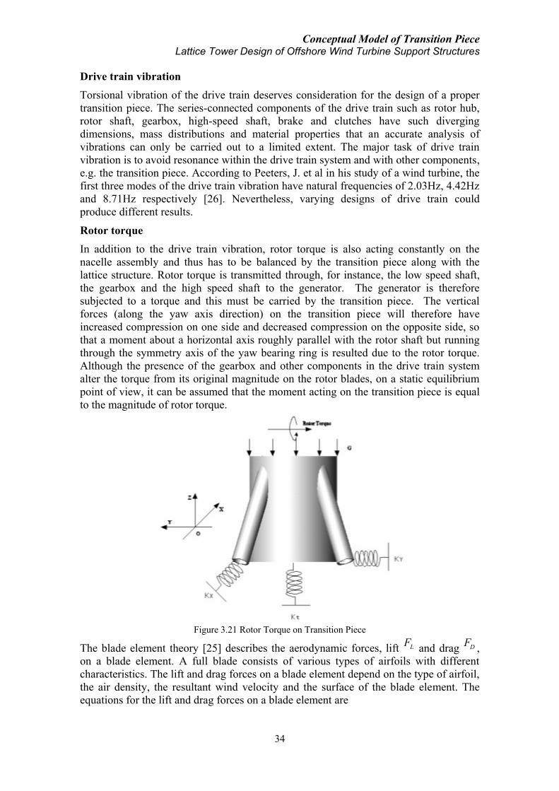
Conceptual Model of Transition Piece Lattice Tower Design of Offshore Wind Turbine Support Structures
34
Drive train vibration
Torsional vibration of the drive train deserves consideration for the design of a proper
transition piece. The series-connected components of the drive train such as rotor hub,
rotor shaft, gearbox, high-speed shaft, brake and clutches have such diverging
dimensions, mass distributions and material properties that an accurate analysis of
vibrations can only be carried out to a limited extent. The major task of drive train
vibration is to avoid resonance within the drive train system and with other components,
e.g. the transition piece. According to Peeters, J. et al in his study of a wind turbine, the
first three modes of the drive train vibration have natural frequencies of 2.03Hz, 4.42Hz
and 8.71Hz respectively [26]. Nevertheless, varying designs of drive train could
produce different results.
Rotor torque
In addition to the drive train vibration, rotor torque is also acting constantly on the
nacelle assembly and thus has to be balanced by the transition piece along with the
lattice structure. Rotor torque is transmitted through, for instance, the low speed shaft,
the gearbox and the high speed shaft to the generator. The generator is therefore
subjected to a torque and this must be carried by the transition piece. The vertical
forces (along the yaw axis direction) on the transition piece will therefore have
increased compression on one side and decreased compression on the opposite side, so
that a moment about a horizontal axis roughly parallel with the rotor shaft but running
through the symmetry axis of the yaw bearing ring is resulted due to the rotor torque.
Although the presence of the gearbox and other components in the drive train system
alter the torque from its original magnitude on the rotor blades, on a static equilibrium
point of view, it can be assumed that the moment acting on the transition piece is equal
to the magnitude of rotor torque.
Figure 3.21 Rotor Torque on Transition Piece
The blade element theory [25] describes the aerodynamic forces, lift LF and drag DF ,
on a blade element. A full blade consists of various types of airfoils with different
characteristics. The lift and drag forces on a blade element depend on the type of airfoil,
the air density, the resultant wind velocity and the surface of the blade element. The
equations for the lift and drag forces on a blade element are

Conceptual Model of Transition Piece Lattice Tower Design of Offshore Wind Turbine Support Structures
35
21
2L air L bF cu C r
21
2D air D bF cu C r
with air air density, c airfoil chord length, u the resultant wind velocity, LC and DC
the lift and drag coefficients and br length of the blade element.
The aerodynamic wind velocity u is the vector sum of the perpendicular and tangential
wind velocities on the blade element. The angle of inflow is the angle between u and
tu . The lift and drag coefficients of the airfoil are related to the angle of attack. The
angle of attack is the angle between the chord line and the resultant wind velocity u ,
which differs at each blade radius due to the twist distribution.
The tangential force tF is expressed as a function of the drag and lift forces:
21( sin cos ) ( sin cos )
2t b L D air b L D bF N F F N cu C C r
with bN the number of blades.
The torque is therefore,
t bQ Fr
with br the rotor blade radius.
The axial and tangential wind velocities are not identical to the free stream wind speed
and the rotational speed, respectively. Due to the presence of the turbine, these wind
velocities are induced. The fractional decrease or increase of the wind velocity is
represented by induction factors (e.g. Eq. 3-2). When wake rotation is included, the
induced velocity at the rotor consists of not only the axial component but also a
component in the rotor plane. The generation of rotational kinetic energy in the wake
results in less extraction by the rotor than would be expected without wake rotation.
Across the flow disk, the angular velocity of the air relative to the blade increases. The
angular induction factor 'a , is defined as ' /a where is the angular velocity
increase and is the original angular velocity.
Applying the conservation of angular momentum, an expression for the rotor torque can
be derived. The torque exerted on the rotor must be equal to the change in angular
momentum. Hence, 24 '(1 )air p b b bQ u r a a r r
Yaw moment
When the incoming wind direction is misaligned with the rotor axis, a component of the
aerodynamic load on the rotor will force the rotor nacelle assembly to rotate along the yaw
axis in order to achieve a smaller angle between the incoming wind direction and the rotor
axis. For modern active yawing concept with motorized yaw drive, yawing of the rotor
nacelle assembly is driven by the motion of the yaw drive, based on result of field
measurement device of the real time wind condition. Nevertheless, before the yaw drive
takes action, a yaw moment will still act on the rotor nacelle assembly which will have to be
(3-7)
(3-8)
(3-9)
(3-10)
(3-11)

Conceptual Model of Transition Piece Lattice Tower Design of Offshore Wind Turbine Support Structures
36
balanced by the support structure through the transition piece. Therefore, the transition
piece is playing an important role of supporting this yaw moment. On a static equilibrium
point of view, the magnitude of the yaw moment load acting on the transition piece should
be equal to the overall yaw moment which is acting on the rotor nacelle assembly.
Magnitude of the yaw moment depends on various factors. The wind condition especially
the angle between the incoming wind direction and the rotor axis plays a very important
role. Aerodynamic properties of the rotating rotor will surely affect the pattern of the yaw
moment. In addition, the distance between the yaw axis and the rotor disk plane is also an
important parameter which determines the length of the yaw moment arm. A short design of
this distance will therefore have advantage of reducing the magnitude of yaw moment on
the transition piece.
Figure 3.22 Misalignment of Incoming Wind with Rotor Axis
Figure 3.23 Yaw Moment on Transition Piece

Conceptual Model of Transition Piece Lattice Tower Design of Offshore Wind Turbine Support Structures
37
Moment of forces
In addition to the above loads, due to the misalignment of the acting point or axis of the
relevant forces and the position of the transition piece, some moments are resulted
acting on the transition piece:
1) Moment of the nacelle weight. The moment arm is the horizontal distance between
the nacelle mass centre and the yaw axis.
2) Moment of the rotor weight. The moment arm is the horizontal distance between the
rotor hub and the yaw axis.
3) Moment of the thrust force. The moment arm is the vertical distance between the yaw
bearing-transition piece interface and the rotor axis. Rotor tilt angle can be negligible.
Therefore, as a summary, the mechanical model of the transition piece taking into
consideration of the boundary condition and various loads can be illustrated as below.
This acts as the mechanical model for the numerical modeling in the following chapters.
Figure 3.24 Mechanical Model of Transition Piece Including Boundary Condition and Various Loads

Conceptual Model of Transition Piece Lattice Tower Design of Offshore Wind Turbine Support Structures
38

Preliminary Design of Transition Piece Lattice Tower Design of Offshore Wind Turbine Support Structures
39
4 PRELIMINARY DESIGN OF TRANSITION PIECE
In this preliminary design procedure, two modeling cases are performed to study the
structural behavior of two types of transition piece concepts under different loading
conditions. Comparative results of the two model types are expected to further optimize
the design of transition piece in the final design process. Structural analysis of transition
piece is conducted on the respective finite element model created in Abaqus [28].
Aerodynamic and hydrodynamic loads are acquired from wind turbine simulation code
HAWC2 [29] in addition to theoretical verification. The loads are then applied on the
transition piece finite element models to study the structural behavior. Methodology is
shown in the Chart below:
Figure 4.1 Methodology for Transition Piece Modeling and Analysis
4.1 Proposed model
Both models are subject to the same geometry configuration requirement, which
includes 6.0m×6.0m area of lattice support structure top and a yaw connection bearing
ring of 5.0m diameter. Diameter of the yaw bearing ring is based on present technology
of the yaw bearing design for a 5MW wind turbine (a typical single-row 4-point contact
ball bearing made from forged rings has a diameter up to 5.0-5.5m for a 5MW turbine
[30]). The total height of the transition piece from the lattice top up to yaw bearing
plane is set at 6.0m including 1.0m height of extension part inside the nacelle assembly
for yaw connection purpose. The basic geometrical configuration is shown in Figure 4.2.
Figure 4.2 Geometrical Configuration Requirement for Transition Piece (Unit: m)
Aerodynamic Loads
Hydrodynamic Loads
HAWC2 Modeling Theoretical Verification
Finite Element Model of
Transition Piece
Transition Piece Structural
Behaviour Analysis

Preliminary Design of Transition Piece Lattice Tower Design of Offshore Wind Turbine Support Structures
40
For both models, steel is used as the material for the whole transition piece. Steel
properties are based on high strength alloy. Material properties including density,
Young’s modulus, Poisson ratio, structural damping, yield strength and ultimate
strength are shown below in Table 4.1.
Table 4.1 Material Properties for Transition Piece
Property Value
Density 7850 kg/ m3
Young’s Modulus 2.1E+11 N/m2
Poisson Ratio 0.3
Structural Damping 1%
Yield Strength 6.9E+8N/ m2
Ultimate Strength 7.6E+8 N/ m2
4.1.1 Frame-cylinder model
As previously described, this model is composed of a cylinder in the middle, a plane in
the bottom and four legs connecting the legs of the lattice support structure and the
cylinder up to the nacelle bottom plane (Figure 4.3). Structural component dimensions
of this model are listed in Table 4.2. The total structural mass is around 118 tons with
mass centre at 2.21m above the base plane.
Figure 4.3 Frame-cylinder Transition Piece Model
Figure 4.4 Cone-strut Transition Piece Model
Structural Component Dimension
Cylinder
Outer Diameter 5.0m,
Thickness 0.1m,
Height 6.0m
Truss
Cross-section:
Outer Diameter 0.9m,
Thickness 0.035m;
Axial Length: 5.3m
Bottom Plane Area 6.0m×6.0m,
Thickness 0.1m
Structural Component Dimension
Cone
Base Outer Diameter 6.0m,
Top Outer Diameter 5.0m,
Thickness 0.1m,
Height 6.0m
Strut
Cross-section:
Outer Diameter 0.9m,
Thickness 0.035m;
Axial Length: 3.0m
Bottom Plane Area 6.0m×6.0m,
Thickness 0.1m
Table 4.2 Structural Dimension of Frame-cylinder TP
Table 4.3 Structural Dimension of Cone-strut TP

Preliminary Design of Transition Piece Lattice Tower Design of Offshore Wind Turbine Support Structures
41
4.1.2 Cone-strut model
Alternatively, the cone-strut type model is also possible to serve as the transition piece.
This model is composed of a truncated cone structure in the middle, a plane in the
bottom covering and connecting the lattice support structure top and four short struts
connecting the legs of the lattice support structure and the cone (Figure 4.4). The struts
are designed in a way that they are connecting with the cone to the mid elevation of the
cone (3.0m high from the bottom plane). Total mass of the structure is about 140 tons
with mass centre at 2.15m above the bottom plane. Structural properties of the model
are shown in Table 4.3.
4.2 Finite element model
4.2.1 Model introduction
For purpose of structural analysis, finite element models of the above two designs are
built (Figure 4.5). Model of the frame-cylinder design remains the same with its
geometrical shape whereas model of the cone-strut design takes off the four short struts
since they are considered to mainly be used for connection between the transition piece
cone and the lattice support structure and to have insignificant contribution to the
strength of the total structure. Meshing information of the two finite element models is
listed in Table 4.4.
(a)Frame-cylinder TP (b)Cone-strut TP
Figure 4.5 Finite Element Models of Transition Piece
Table 4.4 Meshing of the Finite Element Models
Model Type Frame-cylinder
TP
Cone-strut
TP
Criteria for Quadrilateral Elements:
10º smaller face corner angle, 160º
larger face corner angle, 10 aspect
ratio
Criteria for Triangular Elements:
0.01 shape factor, 5º smaller face
corner angle, 170º larger face corner
angle, 10 aspect ratio
Number of Nodes 630 867
Number of Elements 618 812
Line Elements 44# B31 0
Quadrilateral Elements 556# S4R 796# S4R
Triangular Elements 18# S3 16 #S3
Meshing size is based on the compromise of computational cost and sufficiency of
result accuracy. Verification of meshing type and size could be based on assessment of
elements in terms of shape factor, face corner angle, aspect ratio, geometric deviation
factor, edge dimension, stable time increment, etc [31]. A denser meshing of the model

Preliminary Design of Transition Piece Lattice Tower Design of Offshore Wind Turbine Support Structures
42
will in general help increasing the computation accuracy but meanwhile the time cost
will also be amplified. The above too models are found to fulfill the criteria limits
specified and are within a suitable limit of acceptable computational time.
4.2.2 Boundary condition
Boundary condition is dependent on lattice structural stiffness. Based on results in Para.
3.4.1 & 3.4.2, elastic foundation with the following spring coefficients is applied on the
finite element models. Boundary condition is applied at the nodes of the four corners of
the base plane for both models because these nodes are the connection joints with the
lower lattice support structure. All movements in other directions than the ones listed in
Table 4.5 are constrained. The coordination system is referred to Figure 4.6. All
coordination systems in the following paragraphs refer to the same as in Figure 4.6, if
not particularly specified.
Table 4.5 Stiffness of Lattice Support Structure as Boundary Condition
Type Direction Magnitude
Bending X 8.0E+6 N/m
Bending Y 8.0E+6 N/m
Torsion Z 8.0E+8 N∙m/rad
4.2.3 Loading
Description of the relevant loads the transition piece is subjected to and thus to be
applied on the finite element models is given in Para. 3.4.3. Here the detailed loading
conditions with regards to magnitude and direction are shown in Table 4.6. Direction of
the load is according to coordination system in Figure 4.6. Moment direction is based
on right hand coordination system. For load incurred by the drive train vibration,
because the mass of the drive train is included in the rotor nacelle assembly (RNA)
weight, only dynamic analysis of the drive train vibration problem will be considered in
order to assess the probability of resonance between the transition piece and the drive
train vibration.
Figure 4.6 Coordination System Illustration
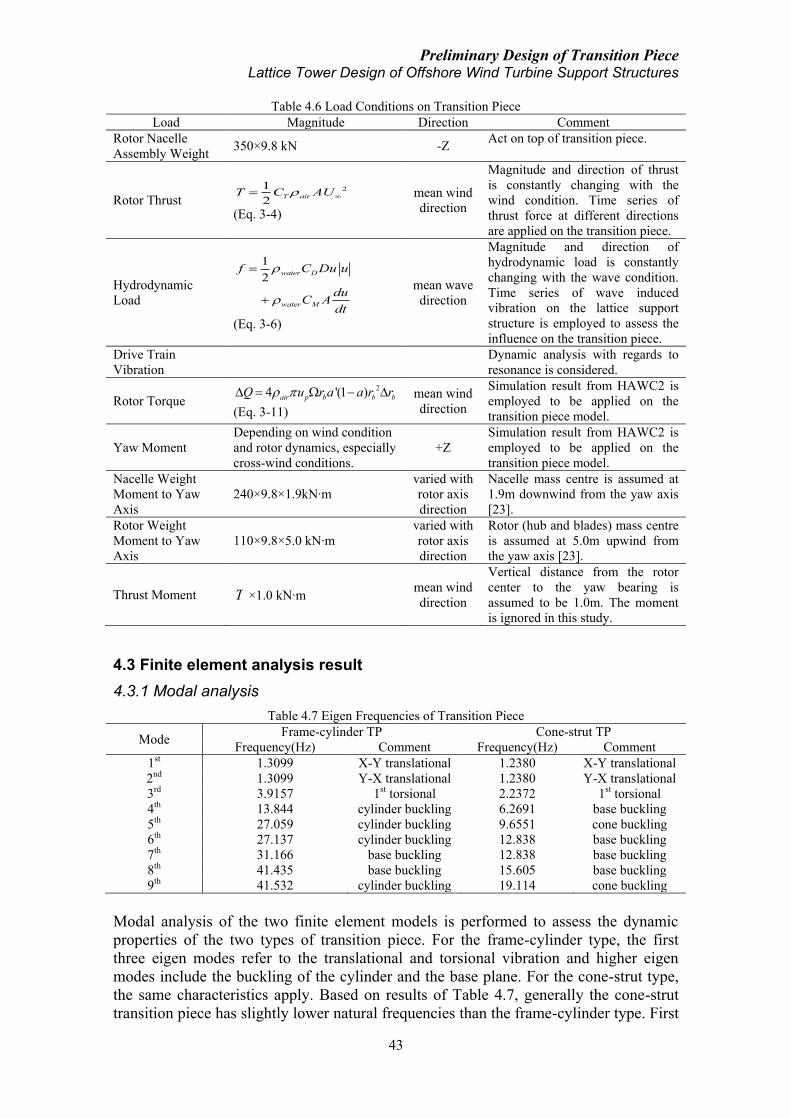
Preliminary Design of Transition Piece Lattice Tower Design of Offshore Wind Turbine Support Structures
43
Table 4.6 Load Conditions on Transition Piece
Load Magnitude Direction Comment
Rotor Nacelle
Assembly Weight 350×9.8 kN -Z
Act on top of transition piece.
Rotor Thrust 21
2T airT C AU
(Eq. 3-4)
mean wind
direction
Magnitude and direction of thrust
is constantly changing with the
wind condition. Time series of
thrust force at different directions
are applied on the transition piece.
Hydrodynamic
Load
1
2
water D
water M
f C Du u
duC A
dt
(Eq. 3-6)
mean wave
direction
Magnitude and direction of
hydrodynamic load is constantly
changing with the wave condition.
Time series of wave induced
vibration on the lattice support
structure is employed to assess the
influence on the transition piece.
Drive Train
Vibration
Dynamic analysis with regards to
resonance is considered.
Rotor Torque 24 '(1 )air p b b bQ u r a a r r
(Eq. 3-11)
mean wind
direction
Simulation result from HAWC2 is
employed to be applied on the
transition piece model.
Yaw Moment
Depending on wind condition
and rotor dynamics, especially
cross-wind conditions.
+Z
Simulation result from HAWC2 is
employed to be applied on the
transition piece model.
Nacelle Weight
Moment to Yaw
Axis
240×9.8×1.9kN∙m
varied with
rotor axis
direction
Nacelle mass centre is assumed at
1.9m downwind from the yaw axis
[23].
Rotor Weight
Moment to Yaw
Axis
110×9.8×5.0 kN∙m
varied with
rotor axis
direction
Rotor (hub and blades) mass centre
is assumed at 5.0m upwind from
the yaw axis [23].
Thrust Moment T ×1.0 kN∙m mean wind
direction
Vertical distance from the rotor
center to the yaw bearing is
assumed to be 1.0m. The moment
is ignored in this study.
4.3 Finite element analysis result
4.3.1 Modal analysis
Table 4.7 Eigen Frequencies of Transition Piece
Mode Frame-cylinder TP Cone-strut TP
Frequency(Hz) Comment Frequency(Hz) Comment
1st 1.3099 X-Y translational 1.2380 X-Y translational
2nd 1.3099 Y-X translational 1.2380 Y-X translational
3rd 3.9157 1st torsional 2.2372 1st torsional
4th 13.844 cylinder buckling 6.2691 base buckling
5th 27.059 cylinder buckling 9.6551 cone buckling
6th 27.137 cylinder buckling 12.838 base buckling
7th 31.166 base buckling 12.838 base buckling
8th 41.435 base buckling 15.605 base buckling
9th 41.532 cylinder buckling 19.114 cone buckling
Modal analysis of the two finite element models is performed to assess the dynamic
properties of the two types of transition piece. For the frame-cylinder type, the first
three eigen modes refer to the translational and torsional vibration and higher eigen
modes include the buckling of the cylinder and the base plane. For the cone-strut type,
the same characteristics apply. Based on results of Table 4.7, generally the cone-strut
transition piece has slightly lower natural frequencies than the frame-cylinder type. First

Preliminary Design of Transition Piece Lattice Tower Design of Offshore Wind Turbine Support Structures
44
eigen modes of the two types of transition piece are shown in Appendix III. Modal
analysis here only considers the selfweight of the transition piece without added mass of
the RNA on top.
4.3.2 RNA weight
RNA weight constitutes a constant component of the total loads that the transition piece
is subjected to endure. In this design, a total RNA mass of 350 tons is used based on
experience of a 5MW wind turbine [23]. The static load is applied on top edge of the
two models and the element stress condition is shown below. Maximum von Mises
stress [32] is 22.37MPa which occurs close to the connection points of the trusses and
the cylinder in the frame-cylinder model whereas maximum von Mises stress in the
other model occurs at the connection points at the base of the cone, which is about
16.31MPa. Stress condition at the connecting points with the base in the frame-cylinder
model is reduced, at the sacrifice of a high local stress condition in the region of the
connecting points on the cylinder. Nevertheless, it can be seen that the cone-strut
transition piece has a better performance, e.g., lower maximum stress, under the static
load of the RNA weight. Stress accumulation at the connection joints of the trusses and
the cylinder in the frame-cylinder type is not unexpected and the maximum stress in this
type of design is over 37% higher than that in the other design.
Figure 4.7 Transition Piece Stress Condition under RNA Weight
In the above analysis, the total weight of the nacelle assembly and the rotor is applied as
constant with time. During the operation period of the turbine, however, due to the
rotating of the rotor blades, the mass of the rotor will have variation with time (Figure
4.8). The frequency of this variation depends on the wind condition and rotor
aerodynamics. The range of oscillation is within ±7% off the mean value. Consideration
of this time variation of the RNA weight due to the rotation of the rotor is not included
in the above analysis.
Because of the misalignment of the yaw axis and the mass centers of the rotor and the
nacelle (Figure 4.9), an eccentric moment is resulted acting on the transition piece.
Ideally the mass centre of the nacelle and the rotor hub can be designed in a way that the
resulted moments will cancel each other at the yaw axis. However, for more realistic
and practical situation, a certain moment will always exit. According to Table 4.6, due
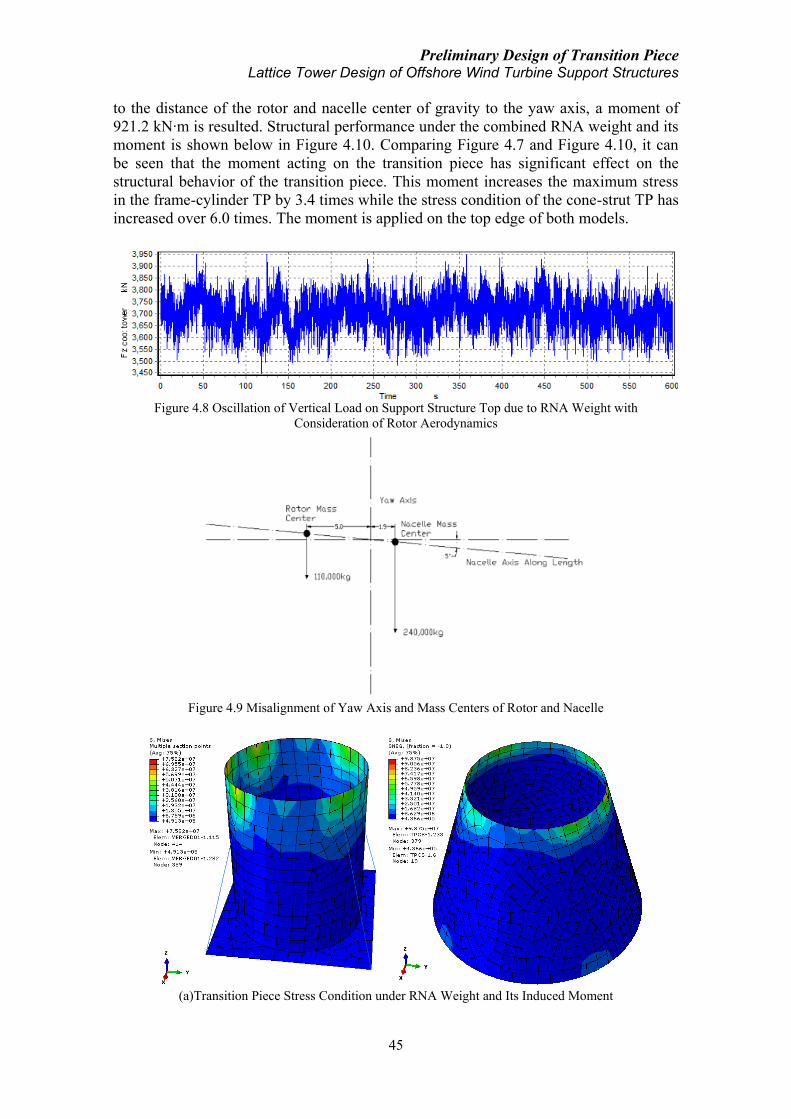
Preliminary Design of Transition Piece Lattice Tower Design of Offshore Wind Turbine Support Structures
45
to the distance of the rotor and nacelle center of gravity to the yaw axis, a moment of
921.2 kN∙m is resulted. Structural performance under the combined RNA weight and its
moment is shown below in Figure 4.10. Comparing Figure 4.7 and Figure 4.10, it can
be seen that the moment acting on the transition piece has significant effect on the
structural behavior of the transition piece. This moment increases the maximum stress
in the frame-cylinder TP by 3.4 times while the stress condition of the cone-strut TP has
increased over 6.0 times. The moment is applied on the top edge of both models.
Figure 4.8 Oscillation of Vertical Load on Support Structure Top due to RNA Weight with
Consideration of Rotor Aerodynamics
Figure 4.9 Misalignment of Yaw Axis and Mass Centers of Rotor and Nacelle
(a)Transition Piece Stress Condition under RNA Weight and Its Induced Moment
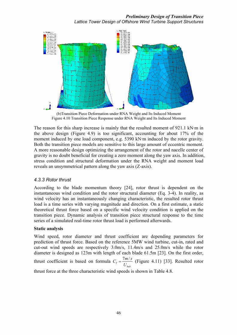
Preliminary Design of Transition Piece Lattice Tower Design of Offshore Wind Turbine Support Structures
46
(b)Transition Piece Deformation under RNA Weight and Its Induced Moment
Figure 4.10 Transition Piece Response under RNA Weight and Its Induced Moment
The reason for this sharp increase is mainly that the resulted moment of 921.1 kN∙m in
the above design (Figure 4.9) is too significant, accounting for about 17% of the
moment induced by one load component, e.g. 5390 kN∙m induced by the rotor gravity.
Both the transition piece models are sensitive to this large amount of eccentric moment.
A more reasonable design optimizing the arrangement of the rotor and nacelle center of
gravity is no doubt beneficial for creating a zero moment along the yaw axis. In addition,
stress condition and structural deformation under the RNA weight and moment load
reveals an unsymmetrical pattern along the yaw axis (Z-axis).
4.3.3 Rotor thrust
According to the blade momentum theory [24], rotor thrust is dependent on the
instantaneous wind condition and the rotor structural diameter (Eq. 3-4). In reality, as
wind velocity has an instantaneously changing characteristic, the resulted rotor thrust
load is a time series with varying magnitude and direction. On a first estimate, a static
theoretical thrust force based on a specific wind velocity condition is applied on the
transition piece. Dynamic analysis of transition piece structural response to the time
series of a simulated real-time rotor thrust load is performed afterwards.
Static analysis
Wind speed, rotor diameter and thrust coefficient are depending parameters for
prediction of thrust force. Based on the reference 5MW wind turbine, cut-in, rated and
cut-out wind speeds are respectively 3.0m/s, 11.4m/s and 25.0m/s while the rotor
diameter is designed as 123m with length of each blade 61.5m [23]. On the first order,
thrust coefficient is based on formula 7 /
T
hub
m sC
U (Figure 4.11) [33]. Resulted rotor
thrust force at the three characteristic wind speeds is shown in Table 4.8.

Preliminary Design of Transition Piece Lattice Tower Design of Offshore Wind Turbine Support Structures
47
Figure 4.11 Thrust Coefficient in Relation to Wind Speed
Table 4.8 Rotor Thrust Load under Characteristic Wind Velocities
Wind Velocity
(m/s)
Rotor
Diameter
(m)
Thrust Coefficient
Theoretical Thrust Force on
Rotor Disk
(kN)
3.0 (cut-in) 123 2.333 290.93
11.4 (rated) 123 0.614 580.74
25.0 (cut-out) 123 0.280 1273.63
Applying the theoretical thrust force of 1273.63kN at 25.0m/s wind velocity on the
models, results of the structural response of the transition piece are shown in Figure
4.12. For the frame-cylinder model, maximum stress of 26.76MPa occurs at the upper
part of the cylinder along the incoming wind direction (Y axis in Figure 4.12) and the
maximum displacement due to this thrust force is about 0.162m. However, because of
the applied boundary condition based on the bending stiffness of the lattice structure,
0.159m displacement is considered to be induced by the bending of the lattice structure
and the deflection of the transition piece itself is negligible. As for the cone-strut model,
maximum stress is 16.67MPa, which is 37.7% lower than the maximum stress in the
frame-cylinder model. Maximum stress occurs at the upper edge of the cone and
structural deflection of the transition piece itself is also ignorable.
(a)Frame-cylinder Model Response under Theoretical Static Thrust Load
0 5 10 15 20 250
0.5
1
1.5
2
2.5
Wind Speed (m/s)
Th
rust C
oe
ffic
ien
t

Preliminary Design of Transition Piece Lattice Tower Design of Offshore Wind Turbine Support Structures
48
(b)Cone-strut Model Response under Theoretical Static Thrust Load
Figure 4.12 Response of Transition Piece under Theoretical Static Thrust Load
Compared with the structural response of transition piece under RNA weight (Figure
4.6), the static rotor thrust force does induce a very comparable structural response of
the transition piece, in terms of structural stress condition. Nevertheless, it is worthy to
mention here that the cone-strut model seems to have an advantageous performance
over the other under the static loads (RNA weight and static thrust force).
Static rotor thrust in combination with RNA weight & moment
After investigation of the structural response to the static theoretical rotor thrust alone,
investigation of the transition piece performance under the combined static rotor thrust
and the RNA weight and moment is done. The result is shown in Figure 4.13.
Two cases are considered in this analysis: the first case is without a yaw angle, i.e. the
thrust force is applied to the –Y direction and the second case is with a yaw angle of 45º,
i.e. the thrust force is applied at 45º from –Y direction, or vector (1, -1, 0) direction in
Figure 4.13. Based on the result below, it can be seen that with a yaw angle of 45º,
maximum structural stress is increased by around 28% in the frame-cylinder model and
decreased by 7.0% in the cone-strut model. The cone-strut model appears to be less
sensitive to the direction of the thrust load which agrees well with its symmetric
geometry profile.
Interestingly, however, comparing results of Figure 4.10(a) and Figure 4.13(a) & (c), it
can be seen that thrust load seems to have eased the stress condition within the
transition piece. The reason can be explained by the opposite trends between the effects
from the RNA weight induced moment and the effects from the thrust force: the RNA
weight induced moment has an effect of tilting the transition piece to the upwind side
while the thrust force is pushing the transition piece to the downwind direction. It can
be by this reason that maximum stress within the transition piece models is even lower
with the addition of thrust load impacting, compared with the case of RNA load alone.

Preliminary Design of Transition Piece Lattice Tower Design of Offshore Wind Turbine Support Structures
49
(a)Stress under Static Thrust & RNA Load (0º Yaw) (b)Stress under Static Thrust & RNA Load (45º Yaw)
(c)Stress under Static Thrust & RNA Load (0º Yaw) (d)Stress under Static Thrust & RNA Load (45º Yaw)
Figure 4.13 Transition Piece Response under Static Thrust and RNA Load
Dynamic analysis
Dynamic analysis of thrust load is performed to assess the structural response of the
transition piece from a dynamic point of view. A 600-second time series of 24m/s mean
wind speed with turbulence intensity of 15.73% is simulated (Figure 4.14). This 24m/s
wind condition is employed to approximate a relatively extreme aerodynamic load
condition for transition piece analysis. Appendix IV provides explanation of this
approximation.
According to Eq. 3-4, theoretical thrust load on a static rotor disk under the above wind
condition is computed as Figure 4.15. Considering the aerodynamic of the rotating rotor,
the actual area of the rotor blades rather than a rotor disk, etc, simulation result of the
rotor thrust load from HAWC2 code is given in Figure 4.16. By comparison of the
theoretical value and the simulated value from HAWC2, it can be seen that the
theoretical value is more conservative in magnitude and the simulated result takes into
consideration the aerodynamics of the rotating blades. Power regulation control
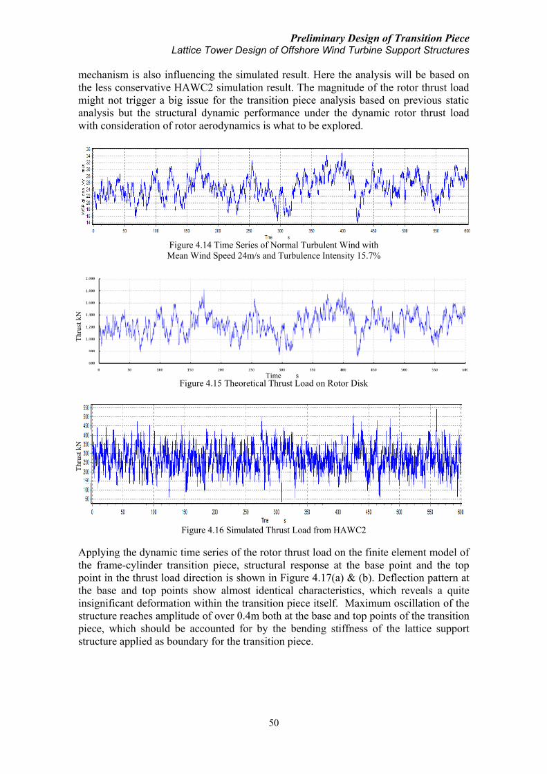
Preliminary Design of Transition Piece Lattice Tower Design of Offshore Wind Turbine Support Structures
50
mechanism is also influencing the simulated result. Here the analysis will be based on
the less conservative HAWC2 simulation result. The magnitude of the rotor thrust load
might not trigger a big issue for the transition piece analysis based on previous static
analysis but the structural dynamic performance under the dynamic rotor thrust load
with consideration of rotor aerodynamics is what to be explored.
Figure 4.14 Time Series of Normal Turbulent Wind with
Mean Wind Speed 24m/s and Turbulence Intensity 15.7%
Figure 4.15 Theoretical Thrust Load on Rotor Disk
Figure 4.16 Simulated Thrust Load from HAWC2
Applying the dynamic time series of the rotor thrust load on the finite element model of
the frame-cylinder transition piece, structural response at the base point and the top
point in the thrust load direction is shown in Figure 4.17(a) & (b). Deflection pattern at
the base and top points show almost identical characteristics, which reveals a quite
insignificant deformation within the transition piece itself. Maximum oscillation of the
structure reaches amplitude of over 0.4m both at the base and top points of the transition
piece, which should be accounted for by the bending stiffness of the lattice support
structure applied as boundary for the transition piece.
Thru
st k
N
Thru
st k
N
Time s

Preliminary Design of Transition Piece Lattice Tower Design of Offshore Wind Turbine Support Structures
51
(a)Displacement at Base Point of Frame-cylinder TP
(b)Displacement at Top Point of Frame-cylinder TP
(c)Displacement at Top Point of Frame-cylinder TP between 150-200s
Figure 4.17 Structural Response of Frame-cylinder TP under Dynamic Thrust Load
Compared with the previous case under theoretical static rotor thrust (Figure 4.12), the
simulated dynamic thrust load is reduced much in magnitude; however, the structural
deformation under this dynamic load appears even more significant. The support
structure applied as transition piece boundary is possible to have amplified vibrational
magnitude under the dynamic thrust load. Nevertheless, transition piece itself shows
negligible deflection within itself.
Under the above dynamic thrust load, the transition piece vibrates symmetrically around
its original static position in the thrust and hence mean wind direction. At time point of
181.6s, the structure reaches maximum negative displacement (Figure 4.18(a)) and at a
later time point of 182.8s, the positive displacement reaches its peak value (Figure
4.18(b)). Detailed thrust load during period of 150s to 200s is shown in Figure 4.19(c).
In addition, the structural response possesses a vibration frequency of about 1.3Hz
(Figure 4.17(c)) which corresponds to the first bending eigen frequency of the transition
piece itself (Table 4.7). If a more complex model is employed taking into the
consideration of the lattice support structure, the response of transition piece should
then inherit both the characteristics of the eigen frequencies of the transition piece and
also that of the lattice support structure. Connection points of the cylinder and the
Time (s)
Dis
pla
cem
ent
(m)
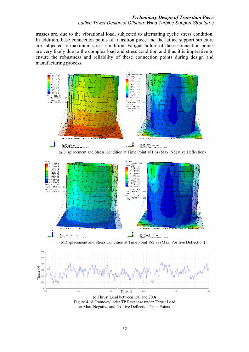
Preliminary Design of Transition Piece Lattice Tower Design of Offshore Wind Turbine Support Structures
52
trusses are, due to the vibrational load, subjected to alternating cyclic stress condition.
In addition, base connection points of transition piece and the lattice support structure
are subjected to maximum stress condition. Fatigue failure of these connection points
are very likely due to the complex load and stress condition and thus it is imperative to
ensure the robustness and reliability of these connection points during design and
manufacturing process.
(a)Displacement and Stress Condition at Time Point 181.6s (Max. Negative Deflection)
(b)Displacement and Stress Condition at Time Point 182.8s (Max. Positive Deflection)
(c)Thrust Load between 150 and 200s
Figure 4.18 Frame-cylinder TP Response under Thrust Load
at Max. Negative and Positive Deflection Time Points
Time (s)
Th
rust
kN

Preliminary Design of Transition Piece Lattice Tower Design of Offshore Wind Turbine Support Structures
53
Applying the same dynamic thrust load on the cone-strut transition piece, structural
response is resulted in Figure 4.19. Similar as the situation for the frame-cylinder TP in
Figure 4.17, maximum vibration amplitude reaches about 0.5m under the dynamic
thrust load, which is again associated with the applied bending stiffness of the lattice
support structure. Structural deflection of the transition piece itself is insignificant. A
significant difference between the responses of the two types of transition piece is the
time point when the maximum structural response takes place. Comparing Figure 4.17(a)
and Figure 4.19(a), it can be easily seen that for the frame-cylinder transition piece,
maximum structural deformation occurs during the first half of the simulation period, i.e.
100s-250s whereas for the cone-strut transition piece, maximum response takes place
during the later stage of the simulation period, i.e. 350s-500s. This difference can
possibly be explained by the differences of the structural dynamics of the two transition
pieces or may be associated with numerical simulation stability. A detailed investigation
of the structural response of the cone-strut transition piece during time period of 450-
500s reveals the structural eigen frequency of 1.2Hz (Figure 4.19(c)), which agrees well
with the result computed in Table 4.7. Structural deflection and stress condition at time
points of maximum displacement is shown in Figure 4.20.
(a)Displacement at Base Point of Cone-strut TP
(b)Displacement at Top Point of Cone-strut TP
(c)Displacement at Top Point of Cone-strut TP between 450-500s
Figure 4.19 Structural Response of Cone-strut TP under Dynamic Thrust
Time (s)
Dis
pla
cem
ent
(m)
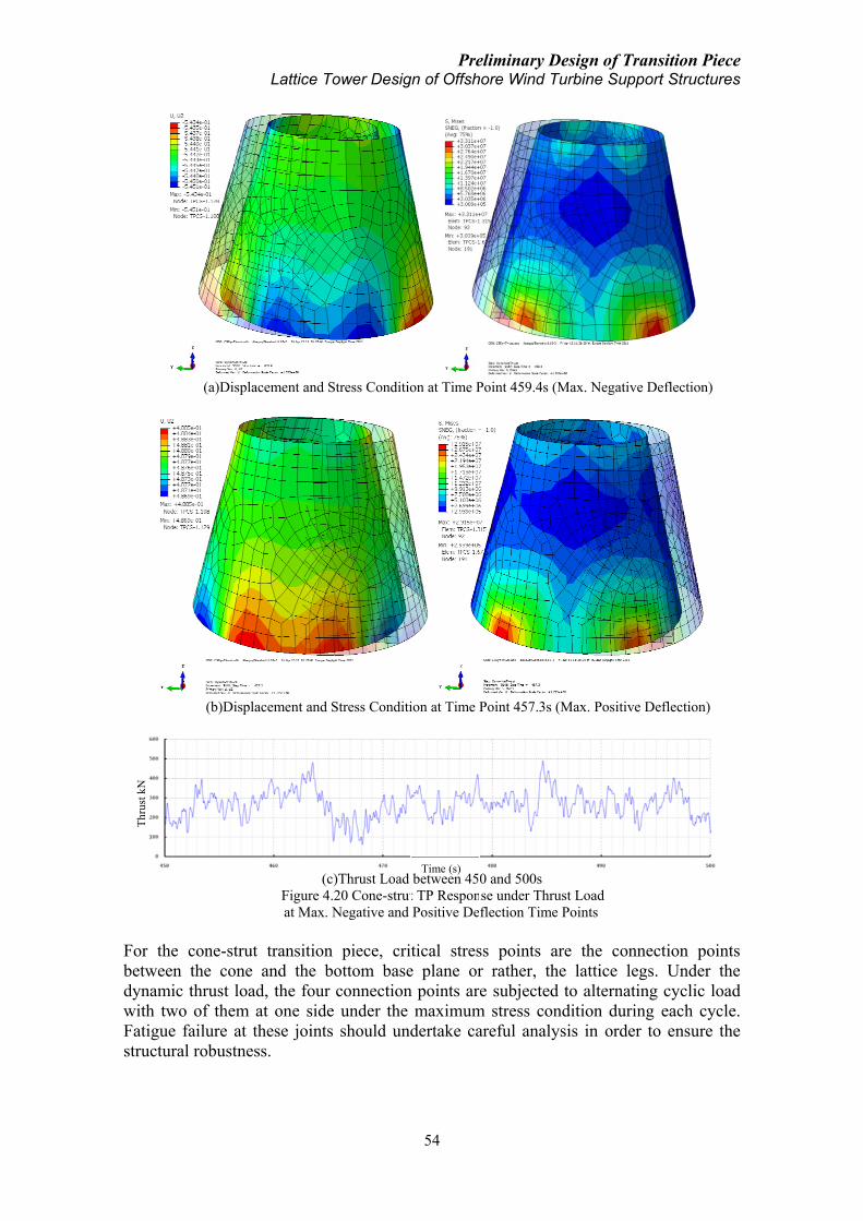
Preliminary Design of Transition Piece Lattice Tower Design of Offshore Wind Turbine Support Structures
54
(a)Displacement and Stress Condition at Time Point 459.4s (Max. Negative Deflection)
(b)Displacement and Stress Condition at Time Point 457.3s (Max. Positive Deflection)
(c)Thrust Load between 450 and 500s
Figure 4.20 Cone-strut TP Response under Thrust Load
at Max. Negative and Positive Deflection Time Points
For the cone-strut transition piece, critical stress points are the connection points
between the cone and the bottom base plane or rather, the lattice legs. Under the
dynamic thrust load, the four connection points are subjected to alternating cyclic load
with two of them at one side under the maximum stress condition during each cycle.
Fatigue failure at these joints should undertake careful analysis in order to ensure the
structural robustness.
Time (s)
Thru
st k
N

Preliminary Design of Transition Piece Lattice Tower Design of Offshore Wind Turbine Support Structures
55
Spectral analysis of the dynamic thrust load simulated from HAWC2 (Figure 4.16) is
shown below. The load, which depends on the wind speed variation and the rotor
dynamics, is majorly composed of low frequency components within the range of 1.0Hz.
However, the frequency range of thrust load is not that likely to encounter with the
natural frequencies of the lattice support structure, e.g., first bending modes at 0.6Hz for
the hard design concept. Dynamic response of lattice support structure under dynamic
rotor thrust load deserves further analysis in next chapter.
Figure 4.21 Power Spectral Density of Simulated Dynamic Thrust Load Time Series
4.3.4 Hydrodynamic load
Transition piece is not subjected to hydrodynamic load directly, however, the lattice
support structure, on which the transition piece sits, is impacted constantly by wave load
in the offshore environment. Two wave conditions are analyzed here where the first one
corresponds to the moderate wave condition with significant wave height of 4.0m and
the second condition corresponds to the more severe wave condition with significant
wave height of 10.0m. Both wave conditions correspond to a wave period of 9.0s and
time series of the irregular Airy waves [37] are generated using Jonswap spectrum [38].
The origin of the coordinate system for hydrodynamic load computation is set at seabed
which makes the water surface at -30m (Figure 4.22). For the first condition of 4.0m
wave, simulated sea surface elevation time series is shown in Figure 4.23. Flow
velocities and accelerations in the incoming wave direction at different water depths
refer to Appendix V.
Figure 4.22 Origin and Coordination for Hydrodynamic Load Computation
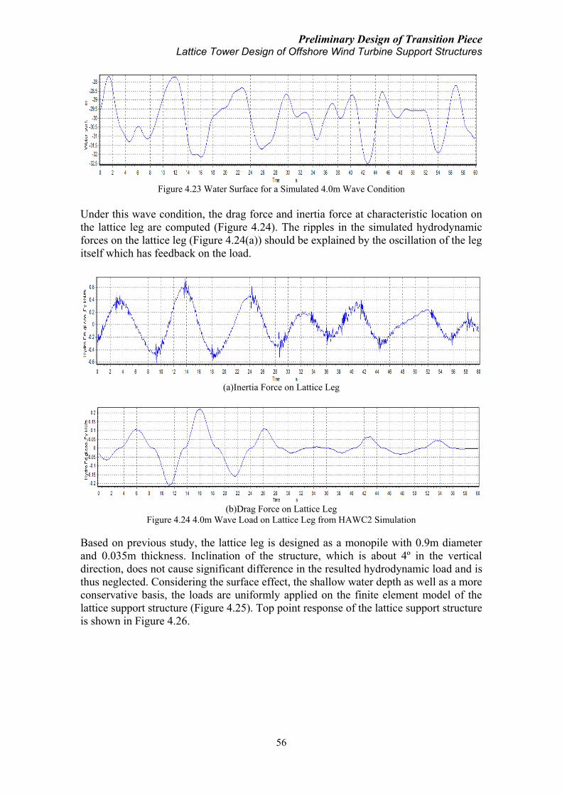
Preliminary Design of Transition Piece Lattice Tower Design of Offshore Wind Turbine Support Structures
56
Figure 4.23 Water Surface for a Simulated 4.0m Wave Condition
Under this wave condition, the drag force and inertia force at characteristic location on
the lattice leg are computed (Figure 4.24). The ripples in the simulated hydrodynamic
forces on the lattice leg (Figure 4.24(a)) should be explained by the oscillation of the leg
itself which has feedback on the load.
(a)Inertia Force on Lattice Leg
(b)Drag Force on Lattice Leg
Figure 4.24 4.0m Wave Load on Lattice Leg from HAWC2 Simulation
Based on previous study, the lattice leg is designed as a monopile with 0.9m diameter
and 0.035m thickness. Inclination of the structure, which is about 4º in the vertical
direction, does not cause significant difference in the resulted hydrodynamic load and is
thus neglected. Considering the surface effect, the shallow water depth as well as a more
conservative basis, the loads are uniformly applied on the finite element model of the
lattice support structure (Figure 4.25). Top point response of the lattice support structure
is shown in Figure 4.26.

Preliminary Design of Transition Piece Lattice Tower Design of Offshore Wind Turbine Support Structures
57
Figure 4.25 Applying Simulated Wave Load on Lattice Support Structure
Figure 4.26 Top Displacement of Lattice Support Structure under 4.0m Wave
In the above result, maximum displacement at the lattice top under this 4.0m wave
condition is negligible (0.3mm amplitude of vibration). A more severe condition of
10.0m wave is thus necessary for further investigation. For this more severe wave
condition, time series of the water surface is shown below. Flow velocities and
accelerations in the incoming wave direction at different water depths are referred to
Appendix V.
Figure 4.27 Water Surface for a Simulated 10m Wave Condition

Preliminary Design of Transition Piece Lattice Tower Design of Offshore Wind Turbine Support Structures
58
The inertia force and drag force at representative location under this 10.0m wave
condition on the same design of lattice leg are computed as below:
(a)Inertia Force on Lattice Leg
(b)Drag Force on Lattice Leg
Figure 4.28 10.0m Wave Load on Lattice Leg from HAWC2 Simulation
Applying the above loads on the lattice structure model, top displacement of the
structure under this 10m wave condition is shown as in Figure 4.29. Even if the
computed response is much more significant than that under the previous 4m wave
condition, nevertheless, this magnitude of response is still within a reasonable and even
negligible range with only 1.5mm amplitude of oscillation.
Figure 4.29 Top Displacement of Lattice Support Structure under 10m Wave
Based on previous analysis of the two wave conditions, the conclusion could be draw
that wave loads induce insignificant response on the top of the lattice support structure.
However, buckling of the truss components below the sea surface under the
hydrodynamic load could be a more important issue (Figure 4.30) which deserves future
research. On the other hand, from the structural dynamics point of view, eigen
frequency of the transition piece which is about 1.2-1.3Hz and the lattice support
structure which is 0.3 or 0.6Hz depending on the type of design should be placed away
from the frequency range of the wave motion, i.e. 0.05-0.2Hz (5s-20s wave period), in
order to avoid structural resonance under the hydrodynamic load. This condition is thus
satisfied here.

Preliminary Design of Transition Piece Lattice Tower Design of Offshore Wind Turbine Support Structures
59
Figure 4.30 Buckling of Trusses below Water Surface of Lattice Support Structure under 10m Wave
4.3.5 Drive train vibration
During the entire operational life time of the wind turbine, drive train is undergoing
rotational vibration. Electrical-mechanical drive train usually refers to the energy
transmission chain without the rotor blades. However, for dynamic consideration, rotor
blades are included here because they constitute the largest share in the rotating masses
(Table 4.9) and play a decisive role in determining the dynamic behavior of the drive
train system whose components have diverging dimensions and mass properties. The
drive train system here is thus referred to the series connected components of rotor
blades, rotor hub, rotor shaft, gearbox, high-speed shaft, etc.
Table 4.9 Mass Proportions of Dynamic Drive Train Components [3]
Wind Turbine Aeroman WKA-60 Growian
Blades 87% 91% 85%
Hub 2% 1% 8%
Generator 9% 7% 5%
Rest 2% 1% 2%
Vibration of the drive train system has its own dynamic characteristics and one of the
major tasks should be to avoid resonance within the drive train system and with other
components in the offshore wind turbine system. If, for instance, the first three modes of
the drive train vibration possess natural frequencies of 2.03Hz, 4.42Hz and 8.71Hz
respectively (Peeters, J. et al [26]), resonance between the vibration of the drive train
and the transition piece torsional motion is likely to occur (Table 4.7). Optimization of
either the drive train design or the transition piece design should be made in order to
minimize the overlap of the eigen frequency range and thus reduce the likelihood of
resonance.
4.3.6 Rotor torque
In addition to drive train torsional vibration, transition piece is subjected to rotor torque
load. Because of the dominating proportion of the rotor (blades and hub), rotor torque

Preliminary Design of Transition Piece Lattice Tower Design of Offshore Wind Turbine Support Structures
60
becomes one significant load. Rotor torque depends on the wind conditions, rotor blades
properties etc (Eq. 3-11). Time series of rotor torque under a normal turbulent wind
condition with mean wind speed 24m/s, turbulence intensity 15.7% and 20º yaw angle
is shown in Figure 4.31. Yaw angle is defined as positive when it comes from the right
hand side, seen from the rotor suction side to the incoming wind direction.
Figure 4.31 Rotor Torque under a Normal Turbulent Wind Condition
The above rotor torque is applied on the finite element models of the transition piece.
The torque is applied at the incoming mean wind direction. For the frame-cylinder type,
displacement in X, Y, Z directions of representative points on the cylinder top edge is
shown in Figure VI.1 in Appendix VI.
Result shows that deflection of representative points at the two sides of the TP has
similar trend in X and Y directions, which indicates a tilting deflection on the upper part
of the TP (Figure 4.32). There is an uneven deflection in the vertical direction and this
deformation is not in the same trend along the Z axis whose reason is because of the
rotor torque, which makes a lifted deflection in the +X side and a pressed deflection in
the –X side (comparing Figure VI.1(c) and VI.1(f)). Structural response is stably
oscillating around a mean value within the period of simulation.
Figure 4.32 Deformation of Frame-cylinder TP under Rotor Torque (Scale Factor 284)
At a specific time point, Stress condition of the TP is shown in Figure 4.33. The
unsymmetrical stress condition due to the rotor torque can be seen and maximum stress
reaches 690.3MPa which is quite significant compared with all previous analysis results.
Therefore, rotor torque has a significant effect on the stress condition of the frame-
cylinder type transition piece and this effect should be very well considered during the
design process.

Preliminary Design of Transition Piece Lattice Tower Design of Offshore Wind Turbine Support Structures
61
Figure 4.33 Frame-cylinder TP Stress Condition at Time Point of Max. Stress under Rotor Torque
For the cone-strut type of transition piece, displacement in the X, Y, Z directions of
representative points on the cone top edge is shown in Figure VI.2. The deflection of the
cone top edge shows similar type of structural deformation under the rotor torque as that
of the frame-cylinder TP. The structure is tilted due to the rotor torque. The cone-strut
TP structural deformation is shown below:
Figure 4.34 Deformation of Cone-strut TP Figure 4.35 Z-displacement of Cone-strut TP
under Rotor Torque under Rotor Torque
Z-displacement of representative nodes in Figure VI.2 does not fully reflect the
deformation of the whole TP structure. Vertical displacement of the cone-strut TP at a
given time point is shown in Figure 4.35. It can be easily seen that the magnitude of Z-
displacement in the left side (-X) of the cone is larger than the magnitude of Z-
displacement in the right side (+X), which corresponds to the effect of rotor torque load
very well. Maximum stress condition of the cone-strut TP is shown in Figure 4.37. The
unsymmetrical stress condition due to the rotor torque can also be seen and the
maximum stress reaches 694.1MPa.

Preliminary Design of Transition Piece Lattice Tower Design of Offshore Wind Turbine Support Structures
62
Figure 4.36 Cone-strut TP Stress Condition at Time Point of Max. Stress under Rotor Torque
Structural deflection of the cone-strut TP is comparable with that of the frame-cylinder
TP. Maximum element stress of the cone-strut TP under the rotor torque load is also
only slightly higher than the situation for the frame-cylinder TP. As the same situation
for both types of the TP, rotor torque has a significant effect on the structural
performance which induces unsymmetrical structural deflection along the axis
approximately parallel to the rotor shaft and increases the maximum structural stress
condition to a significant degree which should be given much attention. Maximum
stress condition of both the frame-cylinder model and the cone-strut model occurs at
time point of 276.5s. Detailed rotor torque load at time interval including this time point
is shown in Figure 4.37. At this time point, the torque load reaches its maximum peak.
Figure 4.37 Rotor Torque between 250 and 300s
4.3.7 Yaw moment
Misalignment of the mean wind direction and the rotor hub axis induces the yawing
motion of the rotor nacelle assembly and the yaw moment will thus have impact on the
behavior of the transition piece. Time series of along-wind speed and cross-wind speed
under a normal turbulent wind condition with mean wind speed 24m/s, turbulence
intensity 15.7% and +20º yaw angle is shown in Figure 4.38. The two wind speed time
series do not have identical trend within the simulation period due to the turbulence
model used. Cross-wind mean speed is about 36% of the along-wind mean speed in
magnitude for this case because of the significant simulated yaw angle of +20º applied.
Due to the cross-wind load on the rotor nacelle assembly, the yaw moment around the
yaw axis is shown in Figure 4.39. Magnitude of the yaw moment depends on the cross-
Time (s)
Torq
ue
kN
m

Preliminary Design of Transition Piece Lattice Tower Design of Offshore Wind Turbine Support Structures
63
wind condition, the rotor aerodynamics and the rotor geometry in relation to the yaw
axis. Simulated time series of the yaw moment under the above mentioned wind model
is generally in phase with the cross-wind time series, with consideration of influence
from the rotor aerodynamics, etc.
(a)Time Series of Along-wind Speed
(b)Time Series of Cross-wind Speed
Figure 4.38 Wind Speed Time Series of a Normal Turbulent Wind Model with +20º Yaw Angle
Figure 4.39 Yaw Moment around Yaw Axis under a Normal Turbulent Wind Model
with +20º Yaw Angle
An important issue to mention is that due to the existence of the yaw bearing and the
yaw drive system (Para. 3.2.2), the direct load on the transition piece should come from
the yaw drive motion and be influenced by the type of yaw bearing. However, for
simplification, the whole rotor nacelle assembly can be regarded as a single body and
the cross-wind load on the rotor can thus be transferred as a yaw moment acting on the
transition piece. In addition, any specifically designed control mechanism should in
general be applied to reduce the load on the wind turbine system. Based on such thought
with a more conservative consideration, the simulated yaw moment is applied on the
finite element models of the transition piece to assess their structural performance under
this loading condition. Similar as previous analysis, structural deformation and stress
condition is the focus.
For the frame-cylinder TP, torsional deformation along the yaw axis under the applied
yaw moment time series can be clearly seen (Figure 4.40 & 4.41). Maximum local
stress reaches 708.6MPa at time point of 553.2s when the magnitude of the yaw

Preliminary Design of Transition Piece Lattice Tower Design of Offshore Wind Turbine Support Structures
64
moment reaches one of its peak negative values (Figure 4.42). Deformation of the TP
depends on the stiffness of the TP itself but in the meanwhile the applied torsional
stiffness of the lattice structure as boundary condition has quite a significant influence.
Maximum rotational displacement along the yaw axis occurs at time point 271.1s when
the peak positive yaw moment is acting on the TP.
(a)X-Displacement (b)Y-Displacement
Figure 4.40 Torsional Structural Deformation of Frame-cylinder TP under
Yaw Moment at a Time Point
Figure 4.41 Rotational Displacement along Yaw-axis Figure 4.42 Stress Condition of Frame-cylinder TP
of Frame-cylinder TP under Yaw Moment at under Yaw Moment at Time Point of Maximum
Time Point of Maximum
For the cone-strut TP model, the same yaw moment load is applied. The structure also
shows torsional deformation along the yaw axis under the load and compared with the
structural response of the frame-cylinder TP, the cone-strut TP has a larger torsional
deformation (Figure 4.43). Maximum structural torsional response happens at time
point of 271.2s when the yaw moment reaches the peak positive magnitude (Figure
4.44). Maximum element stress of the cone-strut TP reaches 743.4MP which is even
higher than the maximum stress of the frame-cylinder TP under the same load condition
(Figure 4.45). This extreme stress event happens also at time point of 553.2s when the
yaw moment reaches its peak negative magnitude. Detailed yaw moment around time
point of maximum negative peak and positive peak values is shown in Figure 4.46.

Preliminary Design of Transition Piece Lattice Tower Design of Offshore Wind Turbine Support Structures
65
(a)X-Displacement (b)Y-Displacement
Figure 4.43 Torsional Structural Deformation of Cone-strut TP under
Yaw Moment at a Time Point
Figure 4.44 Rotational Displacement along Yaw-axis Figure 4.45 Stress Condition of Cone-strut TP
of Cone-strut TP under Yaw Moment at under Yaw Moment at Time Point of Maximum
Time Point of Maximum
(a)Yaw Moment between 250 and 300s
(b)Yaw Moment between 550 and 600s
Figure 4.46 Yaw Moment at Time Interval of Maximum Values
Time (s)
Yaw
Mom
ent
kN
m
Time (s)
Yaw
Mo
men
t k
Nm

Preliminary Design of Transition Piece Lattice Tower Design of Offshore Wind Turbine Support Structures
66
4.4 Conclusion
In the previous section, analysis of structural behaviour of two types of TP concepts
under various loading conditions is performed. The loads analyzed include RNA weight,
RNA weight induced moment, theoretical static rotor disk thrust, dynamic rotor thrust,
drive train vibration, rotor torque and yaw moment. Hydrodynamic load’s impact on the
lattice support structure is also explored in order to assess the magnitude of influence on
the transition piece. Time series of loads including dynamic rotor thrust, rotor torque,
yaw moment and hydrodynamic load on lattice support structure are simulated from
HAWC2 based on employment of wind and wave condition models. Summary of
transition piece and lattice support structure response under various load conditions is
shown in Table 4.10.
Rotor nacelle assembly weight constitutes a constant component on the stress condition
of the transition piece. However, the load due to the weight alone does not trigger a big
problem for the transition piece. Nevertheless, the induced moment due to the
imbalance of the rotor gravity moment and nacelle gravity moment around the yaw axis
leads to some significant increase of stress in both TP designs. It is thus highly
suggested that an optimal design of the rotor and nacelle mass centers be made to avoid
this gravity moment imbalance.
Rotor thrust load does not trigger big problem on the TP models, even if the relatively
extreme wind load model is applied. Nevertheless, it is important to note that dynamic
thrust load does induce an amplified vibration of the transition piece. The reason is
associated with the boundary condition which is artificially applied based on previous
numerical result of lattice support structure. Another issue is that due to the unsteady
characteristics of the thrust load inherited with the instantaneous wind condition,
maximum stress points on the TP will shift from side to side cyclically. Fatigue analysis
at the connection joints of the models will thus be necessary to ensure sufficient
connection robustness.
Magnitude of lattice support structure vibration under the hydrodynamic load depends
on the severity of the wave environment and the lattice structural robustness, especially
the bending stiffness. Simulation result in the above study shows extremely
insignificant vibration of lattice structure top under the wave conditions, whereas
buckling of the lower truss components below the sea surface could be a topic for future
research. Natural frequencies of drive train torsional vibration should be avoided to
overlap with the eigen frequencies of the transition piece, which can be taken care of
during the design of either system.
For the above comparison of the two TP concepts, performance of the frame-cylinder
TP slightly surpasses that of the cone-strut TP in terms of stress condition and structural
deflection under loads of rotor thrust and yaw moment. The cone-strut TP seems only to
possess advantages over the other type under static RNA weight load and theoretical
rotor disk thrust. In this analysis the applied rotor torque and yaw moment could be
over-standard in magnitude because of the applied wind model. However, this still
shows the comparable differences of the structural behaviour of the two concepts under
the rotor torque and the yaw moment.

Preliminary Design of Transition Piece Lattice Tower Design of Offshore Wind Turbine Support Structures
67
Table 4.10 Summary of Transition Piece Behaviour under Various Load Cases
Load Condition Frame-cylinder
TP
Cone-strut
TP
Comment
RNA Weight
Max. Stress 22.37MPa 16.31MPa
Max. Stress
Location
Truss-cylinder
connection points
Cone base
connection points
RNA Weight &
Moment
Max. Stress 75.82MPa 98.75MPa Significant stress
increase due to RNA
weight induced moment Max. Stress
Location
Cylinder top edge
& Truss-cylinder
connection points
Cone top edge &
Cone base
connection points
Theoretical Static
Rotor Disk Thrust
Max. Stress 26.76MPa 16.67MPa Lattice top displacement
is depending on applied
lattice stiffness Max. Stress
Location Cylinder top edge Cone top edge
Structural
Deflection
0.16m at lattice top,
negligible for TP
0.16m at lattice top,
negligible for TP
Static Rotor Disk
Thrust & RNA Load
(0º Yaw)
Max. Stress 66.57MPa 82.03MPa Increased stress
condition due to thrust
direction change for the
frame-cylinder type and
slightly decreased stress
condition due to thrust
direction change for the
cone-strut type
Max. Stress
Location
Cylinder edge &
Truss-cylinder
connection points
Cone edge & Cone
base connection
points
Static Rotor Disk
Thrust & RNA Load
(45º Yaw)
Max. Stress 85.42MPa 76.46MPa
Max. Stress
Location
Cylinder edge &
Truss-cylinder
connection points
Cone edge &
Cone base
connection points
Dynamic Thrust
Max. Stress 28.62MPa 33.11MPa Vibration of lattice
structure depends on
lattice bending stiffness.
Thrust load is based on
normal turbulent wind
with 24m/s speed and
15.7% turbulence
intensity. Magnitude of
vibration is seen as quite
significant in this
simulation study.
Max. Stress
Location
Base connection
points
Base connection
points
Structural
Deflection
±0.46m vibration
for lattice structure,
negligible for TP
±0.55m vibration
for lattice structure,
negligible for TP
Hydrodynamic Load
(4.0m Wave Height)
Structural
Deflection ±0.3mm vibration at lattice top
Irregular Airy wave
model with T=9.0s and
generated by Jonswap
spectrum is applied.
Buckling of lattice
trusses deserve attention
Hydrodynamic Load
(10.0m Wave
Height)
Structural
Deflection ±1.5mm vibration at lattice top
Drive Train
Vibration
Potential
Resonance
Mode
1st torsional mode 1st torsional mode
Depending on specific
design of drive train
system
Rotor Torque
Max. Stress 690.3MPa 694.1MPa Torque load is based on
normal turbulent wind
with 24m/s speed, 15.7%
turbulence intensity and
20º yaw angle.
Max. Stress
Location
Cylinder top edge
& Truss-cylinder
connection points
Cone top edge
Yaw Moment
Max. Stress 708.6MPa 743.4MPa Yaw moment is based
on normal turbulent
wind with 24m/s speed,
15.7% turbulence
intensity and 20º yaw.
Max. Stress
Location Cylinder top edge Cone top edge
Structural
Deflection
8.6º rotation around
yaw axis
11.4º rotation
around yaw axis

Preliminary Design of Transition Piece Lattice Tower Design of Offshore Wind Turbine Support Structures
68

Final Design of Transition Piece Lattice Tower Design of Offshore Wind Turbine Support Structures
69
5 FINAL DESIGN OF TRANSITION PIECE
Based on experience from preliminary analysis of the frame-cone transition piece and
cone-strut transition piece concepts in the previous chapter, here a final design and
analysis of transition piece model is proposed which combines structural strengths from
the previous models and is aiming to meet more practical and functional requirements.
In this final design, a model combing a cone component and a truss system is proposed
which is expected to possess the advantageous characteristics of both types summarized
in Table 4.10. The model here is also designed for a previously introduced lattice
support structure model in Chapter 3 which makes this final design more practically
useful.
5.1 Model geometry
In Para. 3.4.2, analysis of several lattice support structural models is performed (Table
3.5). Final transition piece model is designed for a lattice structure with 4m×4m top
area as is used in all previous lattice designs. Diameter of the base of this transition
piece is thus designed as 5.7m which equals to the diagonal length of the lattice top area,
i.e., 4 2m. As for the upper boundary of the transition piece, the major requirement is a
proper connection with the yaw bearing ring which is introduced in Para. 3.3.2. For
common practice, a yaw bearing of 5.0m diameter is used for 5MW wind turbines [30].
Therefore, the top diameter of the final transition piece is restricted as 5.0m. In addition,
1.0m extension of the transition piece is designed to be placed inside the nacelle
assembly, which is able to allow for a more convenient connection between the nacelle
assembly and the transition piece itself. Height of transition piece (designed as 6.0m in
preliminary analysis) is not subject to specific functional or other requirement which
thus deserves further investigation. The overall geometrical configuration of the
transition piece is shown in Figure 5.1.
Figure 5.1 Geometrical Configuration of Transition Piece
(unit in meter; H to be determined)
Based on the above prerequisite, a truncated cone structure is suitable to meet these
geometrical parameters. To strengthen the robustness of this cone structure, an inner
truss system composed of four truss beams which connects the upper and lower
boundary of the cone is designed. Truss components share a common joint in the center
(Figure 5.2). Connection between this transition piece and the upper yaw bearing ring
H

Final Design of Transition Piece Lattice Tower Design of Offshore Wind Turbine Support Structures
70
is possible by means of bolting of the upper cone edge and the yaw bearing ring. A
robust bolting connection at this location will thus require a sufficient cone shell
thickness otherwise an additional connection flange should be created. On the other
hand, connection of this transition piece to the lower lattice support structure triggers
another challenge. Four short struts are placed at the lower edge of the cone which
connect the four lattice legs and extend upwards on the cone surface (Figure 5.3).
Sufficient welding strength is a crucial requirement for this type of connection. Overall
view of the transition piece is illustrated in Figure 5.4.
Figure 5.2 Joint of Truss Components Figure 5.3 Connection with Lattice Support Structure
Figure 5.4 Overall View of Transition Piece (Scaled for H=6m)
5.2 Structural dimension
In addition to the geometrical configuration, dimension of the structural components has
to be specified. As previously mentioned, transition piece height is a crucial parameter
which influences the total weight, hence cost as well as the structural dynamic
characteristic, e.g. structural eigen frequencies. On the other hand, cone thickness, truss
components dimension, lattice connectors dimension all need to be specified. Figure 5.5

Final Design of Transition Piece Lattice Tower Design of Offshore Wind Turbine Support Structures
71
provides estimate of transition piece weight based on varying heights and cone
thicknesses.
Figure 5.5 Transition Piece Weight with Varying Heights and Cone Thicknesses
Weight estimate in Figure 5.5 includes weight of the inner truss system and lower lattice
connectors. Each truss component is designed as 0.4m diameter with 0.02m thickness
and the connector is designed as 0.9m diameter with 0.04m thickness at the connecting
surface with the lattice leg together with a solid cone connecting the transition piece
cone surface up to half of the transition piece height below nacelle bed level. Weight
restriction of overall 110tons is imposed on this final design and therefore the following
models are filtered after this weight consideration. Table 5.2 shows weight breakdown
of Model 3-20 in Table 5.1 as an example.
Table 5.1 Dimension & Weight of Varying Transition Piece Designs
Model Index 3-10 3-15 3-20 4-10 4-15 5-10 6-10
Height(m) 3.0 3.0 3.0 4.0 4.0 5.0 6.0
Cone Thickness (m) 0.10 0.15 0.20 0.10 0.15 0.10 0.10
Weight Excluding
Lattice Connectors (tons) 44.4 64.2 84.0 58.0 84.4 71.8 85.5
Overall Weight (tons) 54.6 74.4 94.2 71.6 98.0 88.6 105.7
Table 5.2 Weight Breakdown of a 3.0m High, 0.20m Thick Transition Piece
Structural Component Dimension Weight
Cone
Base Outer Diameter 5.7m,
Top Outer Diameter 5.0m,
Thickness 0.2m,
Height 3.0m
79.2tons
Truss
Cross-section:
Outer Diameter 0.4m,
Thickness 0.02m;
Axial Length: 6.1m each
4.48tons
Lattice Connector
Cross-section at Connection:
Outer Diameter 0.9m,
Thickness 0.04m;
Axial Length: 1.0m;
Cone Connector:
Base Diameter 0.9m;
Height 1.0m.
10.2tons
Height(m)
Wei
gh
t(to
ns)

Final Design of Transition Piece Lattice Tower Design of Offshore Wind Turbine Support Structures
72
5.3 Model selection
To select a suitable model among various designs, modal analysis and structural stress
condition under simulated yaw moment load of these designs is computed to provide a
first-order comparison among these different models. Selection of the yaw moment as a
reference load among the others is based on result from previous analysis in Table 4.10
which shows the yaw moment appears to be one of the most critical loads for the
transition piece. The same yaw moment is applied here as in the preliminary analysis
stage where the magnitude and direction of the yaw load is referred to Figure 4.39 &
Table 4.6.
Modal analysis indicates all the designs with varying heights and cone thicknesses have
similar properties. Since the same boundary condition is applied for all the models
(Table 4.5), a lighter design will normally render a model of larger natural frequencies.
Among the designs in Table 5.3, the 1st translational frequency spans from 1.54Hz to
2.13Hz and the 1st torsional frequency ranges between 3.36Hz and 5.25Hz. On the other
hand, all higher order modes of these models refer to cone buckling. The first 12 eigen
modes of Model 3-20 are illustrated in Figure VII.1 in Appendix VII.
Table 5.3 Modal Analysis of Varying Transition Piece Designs
Model Index 3-10 3-15 3-20 4-10 4-15 5-10 6-10
1st Translational Frequency (Hz) 2.13 1.77 1.55 1.87 1.55 1.58 1.54
1st Torsional Frequency (Hz) 5.25 4.72 4.53 4.40 4.00 3.79 3.36
Higher Order Modes
(Up to the 12th Mode) Cone Buckling
Table 5.4 Structural Response of Varying Transition Piece Designs under Yaw Moment
Model Index 3-10 3-15 3-20 4-10 4-15 5-10 6-10
Weight
Excluding
Lattice
Connectors
(tons)
44.4 64.2 84.0 58.0 84.4 71.8 85.5
Maximum
Stress (MPa) 1282 824.2 562.1 1331 748.1 1297 1261
Max. Stress
Location
Cone
Top
Edge
Base
Connection
Points with
Lattice
Substructure
Base
Connection
Points with
Lattice
Substructure
Cone
Top
Edge
Base
Connection
Points with
Lattice
Substructure
Cone
Top
Edge
Cone
Top
Edge
Max.
Structural
Deflection (º)
7.5 3.9 2.6 8.0 4.0 8.4 7.5
Comment For all the designs, maximum stress situation happens at time point of 271.1s when the
yaw moment reaches its peak positive value (Figure 4.46).
As for structural stress condition under the yaw moment load, analysis result shows a
relatively wider range. First of all, it can be easily seen that the increase of the cone
thickness has a significant beneficial effect on the stress condition under the yaw
moment load. On the other hand, influence from the varying heights is not regarded as
significant at all. For all the designs with cone thickness of 100mm, maximum stress
happens at the cone top edge where the yaw moment is applied. However, for thicker
designs of 150mm and 200mm, the most critical regions are shifted to the base
connection points of the transition piece. It therefore proves that there is not much

Final Design of Transition Piece Lattice Tower Design of Offshore Wind Turbine Support Structures
73
specific demand to maintain a very high design whereas it is more meaningful to design
a sufficiently thick model, though at the cost of more material input and perhaps a more
difficult manufacturing process. Two 3m-high models are finally deserving further
consideration based on compromise between the cost and the structural performance.
The final one is focusing on the 3-20 model because of its significantly preferable
structural performance under the yaw moment load, which is shown to be one of the
most critical loads for transition piece from preliminary analysis
5.4 Functional fulfillment
As for functional requirements of transition piece, yaw bearing connection and the
arrangement of the power transmission cable are among the major challenges. As
described in Para. 3.2.1, theoretically, power transmission cable is possible to be
directed from the nacelle assembly through the transition piece and then into one of the
lattice legs (Figure 5.6), though many difficulties have to be solved for the realization of
this ideal method. Practical experience still applies external equipment for the coverage
and protection of power transmission cable (Figure 3.4). Whichever method is going to
be used, the cable inside the transition piece will mostly require a loop for twisting. For
the transition piece design here, there provides sufficient space to allow for the cable
twisting loop. The sufficient space inside the transition piece also allows for
arrangement of climbing stairs for personnel access.
Figure 5.6 Power Transmission Cable inside the Transition Piece
As for connection with the yaw bearing, Figure 5.4 provides the principal method.
Detailed connection method in terms of the type of bolting and whether or not an
addition of specific connection flange will be required depends on the type of yaw
bearing to be used, etc.
5.5 Load analysis
Load analysis of transition piece structural model is the main focus of this thesis. Based
on load analysis results during the preliminary design stage, the type of loads to be
applied on this final transition piece model will majorly stay the same. Table 5.5
includes description of loads to be analyzed for the final design of transition piece

Final Design of Transition Piece Lattice Tower Design of Offshore Wind Turbine Support Structures
74
model 3-20. Various load cases in combination of the loads in Table 5.5 are described in
Table 5.6.
Table 5.5 Load Conditions on Final Transition Piece Design (Coordination refer to Figure 4.6)
Load Magnitude Direction Comment
Rotor Nacelle
Assembly Weight 350×9.8 kN -Z
Act on top edge of
transition piece.
RNA Eccentric
Moment 921.2 kN∙m
Varying
with rotor
axis
direction
Act on top edge of
transition piece.
Rotor Thrust 21
2T airT C AU
(Eq. 3-4)
Refer to
load case
Simulated time series of
thrust load is applied at
different directions on
transition piece model.
Hydrodynamic
Load
1
2
water D
water M
f C Du u
duC A
dt
(Eq. 3-6)
Refer to
load case
Hydrodynamic load is
applied in form of
acceleration time series at
transition piece base in
various load cases.
Drive Train
Vibration
Probability of resonance
should be avoided during
design and selection of
the drive train system.
Rotor Torque
24 '(1 )air p b b bQ u r a a r r
(Eq. 3-11)
Refer to
load case
Simulation result from
HAWC2 is employed to
be applied on transition
piece model.
Yaw Moment
Depending on wind condition and rotor
dynamics, especially cross wind
conditions.
+Z
Simulation result from
HAWC2 is employed to
be applied on transition
piece model.
Table 5.6 Load Cases for Final Transition Piece Analysis
Load Case Description of Situation Comment
RNA At rest or out of operation
RNA + Thrust +
Torque
Operation under aero load Two cases of varying wind directions
RNA + Thrust +
Torque + Hydro
Operation under aero and hydro
loads
Only 10m wave height is considered.
Differing cases of varying directions of wind
and wave loads
RNA + Thrust +
Torque + Yaw
Operation under aero load with
yaw motion
Two cases of varying wind directions
RNA + Thrust +
Torque + Yaw +
Hydro
Operation under aero and hydro
loads with yaw motion
Only 10m wave height is considered.
Differing cases of varying directions of wind
and wave loads
5.5.1 RNA load
Under the RNA load, structural stress condition is shown in Figure 5.7. It can be seen
that compared to the preliminary designs (Para. 4.3.2), stress condition of the final
transition piece design has been improved much. Maximum von Mises stress is only
9.34MPa at the bottom connection joints between the transition piece and the lattice
structure, if only the RNA weight is considered. When the rotor and nacelle weight
induced moment is included, maximum stress reaches 20.2MPa which occurs at the

Final Design of Transition Piece Lattice Tower Design of Offshore Wind Turbine Support Structures
75
upper edge of the cone where this moment load is applied. Structural deformation
under the RNA load is negligible.
(a)Stress under RNA Weight Only (b)Stress under RNA Weight and RNA Moment
Figure 5.7 Stress Condition under RNA Load
Although maximum stress condition under the RNA load is moderate, it can be clearly
seen that the induced moment by the imbalance of the mass center of the nacelle and
rotor has an obvious negative effect on the stress condition of the transition piece. It is
thus meaningful for this moment to be possibly eliminated through a proper design of
the rotor and nacelle mass distribution. To solve this problem, if the below condition is
met, there will be no eccentric moment acting along the yaw axis due to the rotor and
nacelle gravity load. This issue can be taken care of during the design of the turbine.
rotor r nacelle nM L M L (5-1)
where rotorM and nacelleM are the masses of the rotor and the nacelle assembly and rL and
nL are the respective moment arms to the yaw axis.
Figure 5.8 Rotor and Nacelle Mass along Yaw Axis
In the analysis here and the following section, the eccentric moment of RNA is still
included to provide results on a more conservative basis.

Final Design of Transition Piece Lattice Tower Design of Offshore Wind Turbine Support Structures
76
5.5.2 Operation under aero load
For this case rotor thrust and torque loads are applied on the transition piece model to
assess its performance under the aerodynamic load. Applied rotor thrust is under normal
turbulent wind with 24m/s mean wind speed and 15.73% turbulence intensity (Figure
4.16) and rotor torque is based on the same wind model with 15.73% turbulence
intensity but at a slightly lower mean wind speed (Figure 4.31). Identical wind model
could be used to generate simulated rotor thrust and torque. However, the slightly
different mean wind speed used here is regarded as negligible for the purpose of
assessing transition piece dynamic performance.
In the first analysis, the incoming wind direction is from +Y direction (Figure 5.9)
which shares axis with two truss components inside the transition piece. Maximum
structural stress is found to occur at time point 276.5s when the rotor torque reaches its
peak value (Figure 4.37). Critical stress regions are at the diagonal corners on the upper
edge where there is no truss component supporting the cone edge. However, maximum
stress of 201.8MPa is reduced much compared with preliminary design case. Time
series of structural von Mises stress at critical element during the simulation period is
shown in Figure 5.11. Stress condition is in general in phase with rotor torque load
which shows the dominating effect from the torque load.
Figure 5.9 Illustration of Incoming Wind Direction under Aero Load Case
Figure 5.10 Structural Stress Condition at Time Point of Max. Stress under Thrust & Torque Loads
Incoming Wind
Base & Top Points
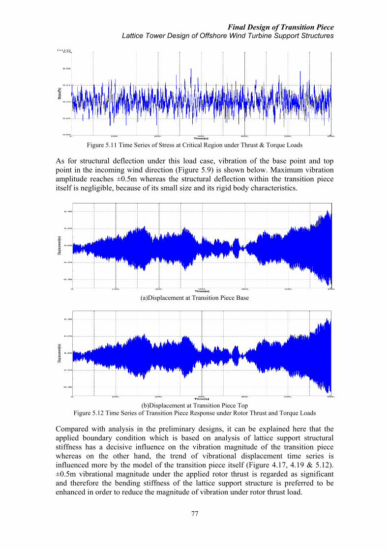
Final Design of Transition Piece Lattice Tower Design of Offshore Wind Turbine Support Structures
77
Figure 5.11 Time Series of Stress at Critical Region under Thrust & Torque Loads
As for structural deflection under this load case, vibration of the base point and top
point in the incoming wind direction (Figure 5.9) is shown below. Maximum vibration
amplitude reaches ±0.5m whereas the structural deflection within the transition piece
itself is negligible, because of its small size and its rigid body characteristics.
(a)Displacement at Transition Piece Base
(b)Displacement at Transition Piece Top
Figure 5.12 Time Series of Transition Piece Response under Rotor Thrust and Torque Loads
Compared with analysis in the preliminary designs, it can be explained here that the
applied boundary condition which is based on analysis of lattice support structural
stiffness has a decisive influence on the vibration magnitude of the transition piece
whereas on the other hand, the trend of vibrational displacement time series is
influenced more by the model of the transition piece itself (Figure 4.17, 4.19 & 5.12).
±0.5m vibrational magnitude under the applied rotor thrust is regarded as significant
and therefore the bending stiffness of the lattice support structure is preferred to be
enhanced in order to reduce the magnitude of vibration under rotor thrust load.

Final Design of Transition Piece Lattice Tower Design of Offshore Wind Turbine Support Structures
78
For the second analysis case, the incoming wind direction is changed to come from 45º
between +Y & +X direction (Figure 5.13) whereas all the other load conditions are kept
the same. This case is to explore the sensitivity of transition piece to varied load
directions. Maximum structural stress is found to occur at time point 276.5s when the
rotor torque reaches its peak value (Figure 4.37). Critical stress regions are again at the
diagonal corners on the upper edge where there is no truss component supporting the
cone edge. However, for this angled case, maximum stress reaches 239.4MPa which is
19% higher than the previous unangled case. Therefore, the transition piece model
shows a certain degree of sensitivity to the aero load direction, which is mostly because
of the nonuniform alignment of the inner truss system. Time series of structural von
Mises stress at critical element during the simulation period is shown in Figure 5.15.
Stress condition is also in general in phase with rotor torque but the magnitude of the
stress is increased comparing Figure 5.11 & 5.15.
Figure 5.13 Illustration of Incoming Wind Direction under Angled Aero Load Case
Figure 5.14 Transition Piece Stress Condition at Time Point of Max. Stress under
Angled Thrust & Torque Loads
Incoming Wind
Base & Top Points

Final Design of Transition Piece Lattice Tower Design of Offshore Wind Turbine Support Structures
79
Figure 5.15 Time Series of Stress at Critical Region under Angled Thrust & Torque Loads
As for structural deflection under this load case, transition piece vibrates along the
incoming wind direction Figure 5.16. Maximum vibration amplitude reaches ±0.4m
which is slightly reduced compared to the previous case. The reason for this reduction is
that the overall bending stiffness at this angled direction is increased to 2 times of the
original value. The trend of the vibrational displacement time series is in general the
same as the unangled case (Figure 5.12 & 5.17). Due to the existence of rotor torque,
vibrations at X and Y directions are not exactly identical both in phase and in magnitude.
Figure 5.16 Transition Piece Vibration under Angled Thrust & Torque Loads
As previously stated, vibration of the transition piece under the applied thrust load
reaches a magnitude that is regarded as too significant for normal operation. Resulted
magnitude of vibration has to be influenced by the applied boundary condition.
Parameters for the applied boundary condition are based on analysis of various lattice
support structure models in Chapter 3 (Table 3.4). In order to further explore the
influence from this applied boundary, the same thrust load is applied on a lattice support
structure model (Table 3.5 stiff). Time series of displacement and acceleration at the
lattice top is shown in Figure 5.19.
Comparing response of transition piece and that of the lattice support structure under the
same thrust load, it can be seen that vibration of the transition piece is influenced by the
applied boundary condition. However, vibration of transition piece includes higher
frequency components which should come from the eigen frequency of the transition
piece itself. Vibration magnitude of lattice structure (±0.3m) is found to be less than that
of transition piece (±0.5m). One reason for this could be the less conservative value of

Final Design of Transition Piece Lattice Tower Design of Offshore Wind Turbine Support Structures
80
bending stiffness used (8.0E+6 N/m) compared to the actual bending stiffness of the
lattice structure (8.76E+6 N/m). In addition, the simplified spring boundary condition
which only takes the first mode of the lattice support structure and thus loses its higher
modes strength might account for another reason.
(a)Displacement in X & Y Direction at Transition Piece Base
(b)Displacement in X & Y Direction at Transition Piece Top
Figure 5.17 Time Series of Transition Piece Response under Angled Rotor Thrust and Torque Loads

Final Design of Transition Piece Lattice Tower Design of Offshore Wind Turbine Support Structures
81
Figure 5.18 Thrust Load Applied on Top of Lattice Support Structure
(a)Displacement at Lattice Top under Thrust Load
(b)Acceleration at Lattice Top under Thrust Load
Figure 5.19 Lattice Structural Response to Thrust Load
5.5.3 Operation under aero load with yaw motion
In this load case, yaw moment load is acting on transition piece along with the
previously described rotor thrust and rotor torque. Thrust and torque loads remain the

Final Design of Transition Piece Lattice Tower Design of Offshore Wind Turbine Support Structures
82
same as employed in the previous analysis and the applied yaw moment is referred to
Figure 4.39. This yaw moment is simulated based on the same normal turbulent wind
model with 24m/s mean wind speed, 15.73% turbulence intensity and 20º yaw angle.
For the first case, rotor axis is aligned with +Y direction while for the second case rotor
axis is aligned at 45º between +Y & +X direction (Figure 5.20).
Figure 5.20 Illustration of Rotor Axis Direction
Under the first case, maximum structural stress occurs at time point 271.1s when the
yaw moment reaches its peak value (Figure 4.46). Maximum stress of 565.3MPa occurs
at the four base connection points. Time series of von Mises stress at the most critical
joint is shown in Figure 5.22. It can be seen that stress condition at the joint has a
significant vibration in stress magnitude which deserves fatigue analysis. The trend of
stress time series is in general in phase with the yaw moment load (Figure 4.39). An
enhanced design of the truss system could be expected to possibly reduce the stress
condition under the yaw load. Structural deformation under this load case is composed
of translational vibration due to rotor thrust and torsional vibrational due to yaw
moment (Figure 5.23).
Figure 5.21 Transition Piece Stress Condition at Time Point of Max. under Aero Load with Yaw Motion
First Analysis Case
Second Analysis Case

Final Design of Transition Piece Lattice Tower Design of Offshore Wind Turbine Support Structures
83
Figure 5.22 Time Series of Stress at Critical Truss Joint under Aero Load with Yaw Motion
Figure 5.23 Transition Piece Deformation under Aero Load with Yaw Motion
For the torsional vibration due to yaw moment, critical region happens at cone upper
edge. Time series of torsional vibration along the yaw axis at critical node is shown in
Figure 5.24. Magnitude of vibration ranges from -1.4º to 2.7º whereas the phase of
vibrational motion keeps with that of the yaw moment load. As for translational
vibration under the thrust load, Figure 5.25 shows displacement time series at X(U1,
green line) and Y(U2, blue line) directions. X displacement is caused by the yaw
rotational motion which also keeps in phase with the yaw moment load. Y displacement
follows the rotor thrust load.
Figure 5.24 Torsional Vibration along Yaw Axis at Critical Node under Aero Load with Yaw Motion
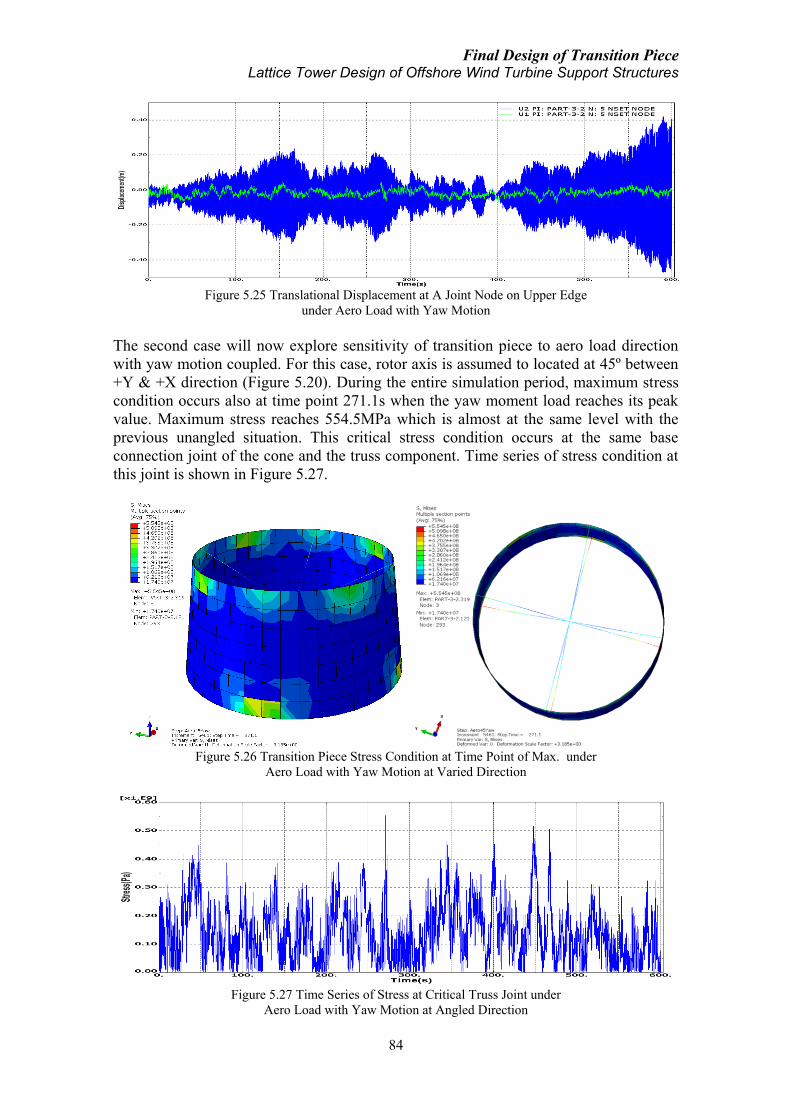
Final Design of Transition Piece Lattice Tower Design of Offshore Wind Turbine Support Structures
84
Figure 5.25 Translational Displacement at A Joint Node on Upper Edge
under Aero Load with Yaw Motion
The second case will now explore sensitivity of transition piece to aero load direction
with yaw motion coupled. For this case, rotor axis is assumed to located at 45º between
+Y & +X direction (Figure 5.20). During the entire simulation period, maximum stress
condition occurs also at time point 271.1s when the yaw moment load reaches its peak
value. Maximum stress reaches 554.5MPa which is almost at the same level with the
previous unangled situation. This critical stress condition occurs at the same base
connection joint of the cone and the truss component. Time series of stress condition at
this joint is shown in Figure 5.27.
Figure 5.26 Transition Piece Stress Condition at Time Point of Max. under
Aero Load with Yaw Motion at Varied Direction
Figure 5.27 Time Series of Stress at Critical Truss Joint under
Aero Load with Yaw Motion at Angled Direction

Final Design of Transition Piece Lattice Tower Design of Offshore Wind Turbine Support Structures
85
Under this load case, deformation of the transition piece is composed of torsional
vibration under yaw moment load and translational vibration at 45º between +Y & +X
direction under rotor thrust (Figure 5.28). Torsional vibration time series at critical
element is shown in Figure 5.29 which is very close to previous analysis result in Figure
5.24.
Figure 5.28 Transition Piece Deformation under Aero Load with Yaw Motion at Angled Direction
Figure 5.29 Torsional Vibration along Yaw Axis at Critical Node under
Aero Load with Yaw Motion at Angled Direction
As for translational vibration under the thrust load component, motion of a node at the
thrust load direction on upper cone edge is shown below. Vibration in both X(U1, green
line) and Y(U2, blue line) directions are generally identical both in magnitude and phase.
The difference should be accounted by the influence from rotor torque and yaw
moment’s twisting effect.
Figure 5.30 Time Series of Transition Piece Response under
Aero Load with Yaw Motion at Angled Direction

Final Design of Transition Piece Lattice Tower Design of Offshore Wind Turbine Support Structures
86
By far transition piece response to aerodynamic loads are investigated. Yaw moment
load appears to be the most critical one among all the other loads under various load
cases. Transition piece deformation to yaw moment load is not significant; however, its
response to rotor thrust reaches a vibration magnitude that deserves much attention for
practical purpose. Response of transition piece shows a certain degree of sensitivity to
varied load directions, nevertheless, the difference is not beyond expectation. In the
following, influence from the hydrodynamic load on the lattice support structure is
explored in combination with the above aerodynamic loads.
5.5.4 Operation under aero & hydro load at identical wind wave direction
In order to explore transition piece response to coupled aero and hydro loads, 600s time
series of hydro load properties is simulated to match the entire aero load simulation
period. By experience in the preliminary analysis, 10m high irregular Airy wave with 9s
period is generated to compute the hydro load on the lattice support structure and its
response. Water surface elevation and the inertia and drag loads at representative point
on the submerged part of the lattice support structure are shown respectively in figure
below.
(a)Water Surface Elevation for a 10m Irregular Airy Wave (Sea Surface at -30m (Figure 4.22))
(b)Inertia Force on Lattice Leg
(c)Drag Force on Lattice Leg
Figure 5.31 Water Surface Elevation and Hydro Load of a 10m Irregular Airy Wave on Lattice Leg

Final Design of Transition Piece Lattice Tower Design of Offshore Wind Turbine Support Structures
87
The above hydro load is applied on the lattice support structure and the response of
lattice structure top point in form of displacement, velocity and acceleration time series
is shown in Figure 5.32. Magnitude of vibration reaches ±1.0mm which generally
agrees with the 60s simulation result in previous preliminary analysis (Figure 4.29).
Acceleration time series are then applied on transition piece base as a boundary load in
combination with the relevant aero loads to investigate transition piece response under
combined aero and hydro loads.
(a)Displacement Time Series at Lattice Top under Hydro Load
(b)Velocity Time Series at Lattice Top under Hydro Load
(c)Acceleration Time Series at Lattice Top under Hydro Load
Figure 5.32 Lattice Support Structure Response to 10m Wave Load
In the first case, time series of acceleration at lattice top (Figure 5.32(c)) and time series
of dynamic thrust load (Figure 5.19(b)) are applied at the same direction at 45º between
+Y & +X direction (Figure 5.33) on transition piece base and top edge respectively, in
addition to rotor torque moment on transition piece top edge, to explore the combined
effects of hydro load, thrust load and rotor torque on the transition piece structural
model. In this case the direction of the incoming wind and wave is thus assumed
identical.

Final Design of Transition Piece Lattice Tower Design of Offshore Wind Turbine Support Structures
88
Figure 5.33 Illustration of Identical Incoming Wind & Wave Direction
Figure 5.34 Transition Piece Stress Condition at Time Point of Max. under
Aero & Hydro Load from Identical Direction
Structural stress condition under this case is almost the same with previous analysis
without the hydro load (Figure 5.14). Maximum stress reaches almost the same value
and occurs at the same location (Figure 5.34). Displacement under the combined load at
the transition piece base and top in X and Y directions is shown in Figure 5.35. Due to
the removal of spring system as the boundary, transition piece response is generally
following the lattice top response under the hydro load while the rotor thrust does not
present severe problem on the transition piece vibration any more.
(a)X-displacement at TP Top(blue) and Base(green)
Incoming Wave Incoming Wind
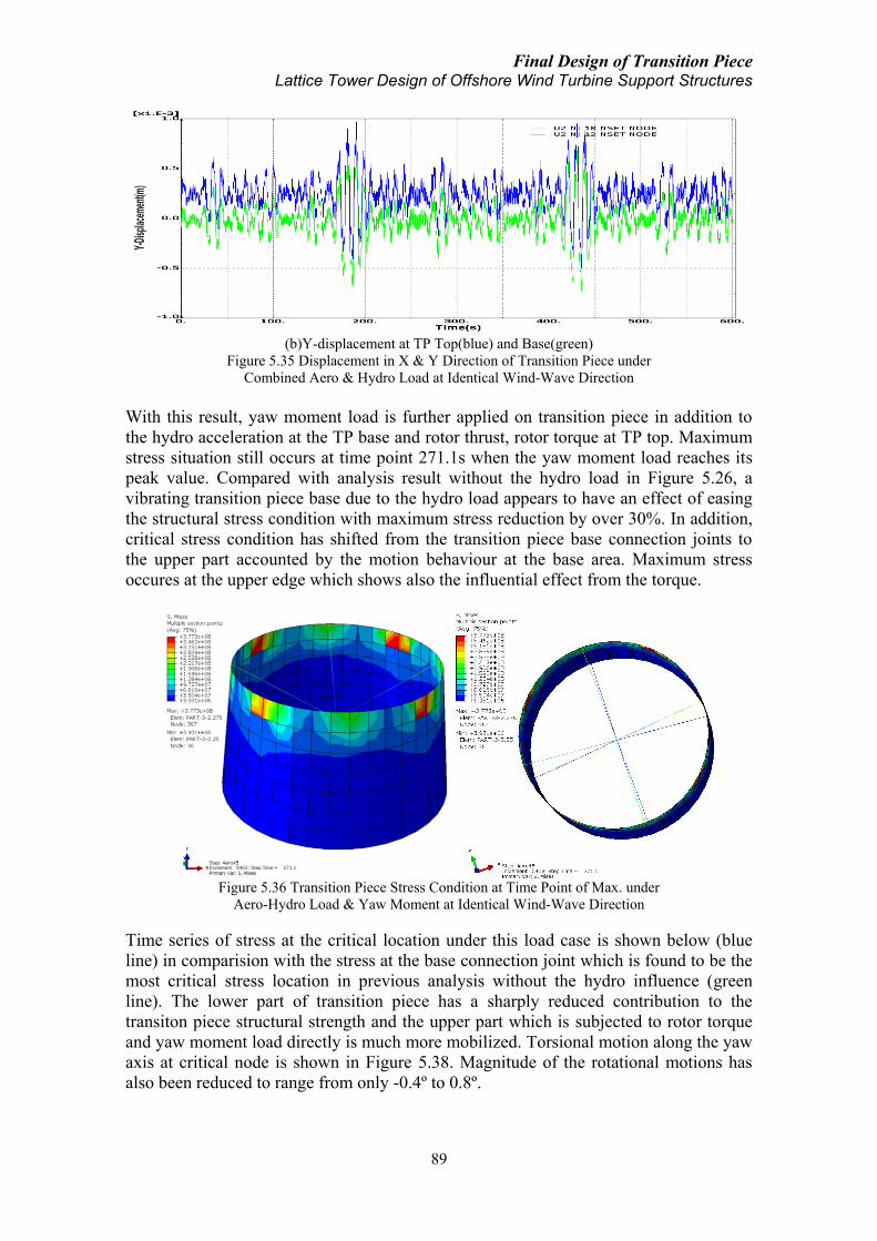
Final Design of Transition Piece Lattice Tower Design of Offshore Wind Turbine Support Structures
89
(b)Y-displacement at TP Top(blue) and Base(green)
Figure 5.35 Displacement in X & Y Direction of Transition Piece under
Combined Aero & Hydro Load at Identical Wind-Wave Direction
With this result, yaw moment load is further applied on transition piece in addition to
the hydro acceleration at the TP base and rotor thrust, rotor torque at TP top. Maximum
stress situation still occurs at time point 271.1s when the yaw moment load reaches its
peak value. Compared with analysis result without the hydro load in Figure 5.26, a
vibrating transition piece base due to the hydro load appears to have an effect of easing
the structural stress condition with maximum stress reduction by over 30%. In addition,
critical stress condition has shifted from the transition piece base connection joints to
the upper part accounted by the motion behaviour at the base area. Maximum stress
occures at the upper edge which shows also the influential effect from the torque.
Figure 5.36 Transition Piece Stress Condition at Time Point of Max. under
Aero-Hydro Load & Yaw Moment at Identical Wind-Wave Direction
Time series of stress at the critical location under this load case is shown below (blue
line) in comparision with the stress at the base connection joint which is found to be the
most critical stress location in previous analysis without the hydro influence (green
line). The lower part of transition piece has a sharply reduced contribution to the
transiton piece structural strength and the upper part which is subjected to rotor torque
and yaw moment load directly is much more mobilized. Torsional motion along the yaw
axis at critical node is shown in Figure 5.38. Magnitude of the rotational motions has
also been reduced to range from only -0.4º to 0.8º.
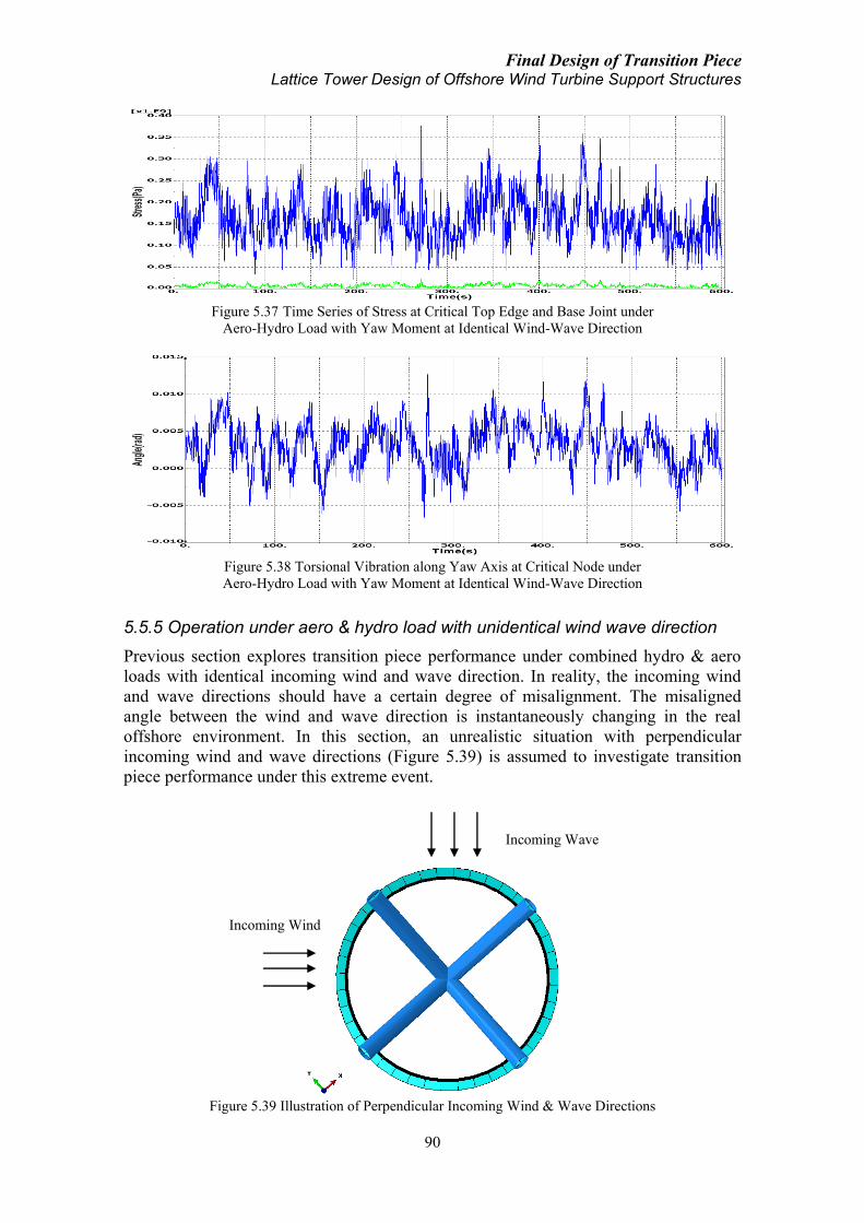
Final Design of Transition Piece Lattice Tower Design of Offshore Wind Turbine Support Structures
90
Figure 5.37 Time Series of Stress at Critical Top Edge and Base Joint under
Aero-Hydro Load with Yaw Moment at Identical Wind-Wave Direction
Figure 5.38 Torsional Vibration along Yaw Axis at Critical Node under
Aero-Hydro Load with Yaw Moment at Identical Wind-Wave Direction
5.5.5 Operation under aero & hydro load with unidentical wind wave direction
Previous section explores transition piece performance under combined hydro & aero
loads with identical incoming wind and wave direction. In reality, the incoming wind
and wave directions should have a certain degree of misalignment. The misaligned
angle between the wind and wave direction is instantaneously changing in the real
offshore environment. In this section, an unrealistic situation with perpendicular
incoming wind and wave directions (Figure 5.39) is assumed to investigate transition
piece performance under this extreme event.
Figure 5.39 Illustration of Perpendicular Incoming Wind & Wave Directions
Incoming Wind
Incoming Wave

Final Design of Transition Piece Lattice Tower Design of Offshore Wind Turbine Support Structures
91
In the first analysis case, aero loads include rotor thrust and rotor torque from the
incoming wind direction while yaw moment is excluded. As for the hydro load,
acceleration response of lattice top under the previously applied 10.0m wave is acting
on the transition piece base to simulate the hydro effect on transition piece. Maximum
stress condition occurs at time point 276.5s when the rotor torque load reaches the peak
value, which agrees with previous analysis without the hydro influence (Figure 5.14).
Figure 5.40 Transition Piece Stress Condition at Time Point of Max. under Aero & Hydro Load with
Perpendicular Wind-Wave Direction (Transparent Model is the Initial Undeformed Structural Model)
Location of critical stress condition is also at the two sides on the upper edge
perpendicular to the incoming wind direction. The dominating effect of rotor torque
load is obviously seen and the structure shows obvious tilting deformation under the
torque load (Figure 5.40). Time series of stress at critical location is shown in Figure
5.41. As for structural response, transition piece is basically vibrating under the hydro
influence while the effect of the rotor thrust is not representing any more.
Figure 5.41 Time Series of Stress at Critical Location under
Aero & Hydro Load with Perpendicular Wind-Wave Direction
For the second analysis case, yaw moment load is applied on transition piece in addition
to the above loads. Maximum stress condition is found to occur at time point 271.1s
when the yaw moment reaches its peak value, which agrees well with all the previous
load cases that contain the yaw moment load. Maximum stress of 377.3MPa in this case
is the same compared with previous case of identical incoming wind and wave direction
(Figure 5.36) and reduced by 32% if it’s compared with the case without including the

Final Design of Transition Piece Lattice Tower Design of Offshore Wind Turbine Support Structures
92
hydro effect (Figure 5.26). Maximum stress occurs on the upper edge of transition piece
where all the aero loads are directly acting on.
Figure 5.42 Transition Piece Stress Condition at Time Point of Max. under Aero & Hydro Load with
Yaw Moment with Perpendicular Wind-Wave Direction (Transparent Model is the Undeformed Model)
Due to the imposed vibrating motion at transition piece base based on hydro load
analysis, critical stress location are mostly shifted to the upper part of the transition
piece structure while the lower part is not as much as mobilized as in the case of a non-
vibrating base without the hydro influence (Figure 5.26), which also agrees with
previous case analysis with identical incoming wind-wave direction (Figure 5.36).
Comparing this analysis case with the previous one without including the yaw moment
load (Figure 5.40), it can be seen that location of maximum stress has changed, which
can only be explained by the additional effect from the yaw moment load. Time series
of stress at critical location is shown in figure below. The stress time series is in general
following the yaw moment load (Figure 4.39) with influence from the thrust, torque and
hydro loads.
Figure 5.43 Time Series of Stress at Critical Location under Aero & Hydro Load with Yaw Moment
with Perpendicular Wind-Wave Direction
As for structural response under this load case, transition piece vibration includes the
hydrodynamic related vibration in the incoming wave direction, the torsional motion
around the yaw axis due to the yaw moment and the tilting deformation under the rotor
torque while the rotor thrust effect is insignificant. Torsional vibration at critical node
under this load case is shown in Figure 5.45. The magnitude of vibration along the yaw

Final Design of Transition Piece Lattice Tower Design of Offshore Wind Turbine Support Structures
93
axis is very close to the result under identical wind-wave direction analysis (Figure
5.38).
Figure 5.44 Transition Piece Response under Aero & Hydro Load with Yaw Moment
with Perpendicular Wind-Wave Direction (Transparent Model is the Undeformed Model)
Figure 5.45 Torsional Vibration along Yaw Axis at Critical Node under
Aero-Hydro Load with Yaw Moment with Perpendicular Wind-Wave Direction
As a summary, Para. 5.5.4 & 5.5.5 try to explore transition piece structural model
response under the combined hydro and aero loads. Maximum stress conditions have
shown reduction by the induced motion at transition piece base due to the
hydrodynamic load under the yaw moment load. With yaw moment load, simulation
results indicate that vibrating transition piece base due to the hydrodynamic effect has
an effect of shifting the load bearing zone from the lower part of transition piece to the
upper edge where the aero dynamic loads are applied. However, contributing effect
from the inner truss system is clearly seen under yaw moment load. The inner truss
system can be further enhanced to achieve a better structural robustness to resist the yaw
moment load.
Comparing analysis results of Para. 5.5.4 & 5.5.5, it can be concluded that varying
wind-wave misalignment does not lead to severe difference on transition piece
structural behaviour. Maximum stress condition is nearly the same when the incoming
wind and wave direction is identical or perpendicular. Structural deformation pattern is
changed by the change of wind and wave directions but in no case the structural
deformation appears too severe calling for special attention. Transition piece
performance under all the previous load cases is summariezed in Table 5.7.

Final Design of Transition Piece Lattice Tower Design of Offshore Wind Turbine Support Structures
94
Table 5.7 Transtion Piece Response under Various Load Cases
Load Case Transition Piece Performance Comment
RNA Weight
Max. Stress 9.34MPa
Max. Stress
Location Base connection joints
RNA Weight &
Moment
Max. Stress 20.24MPa Stress increase due to RNA weight
induced moment. The moment is
applied on cone top edge. Max. Stress
Location Cone top edge
Aero Load
(Thrust & Torque)
Max. Stress 201.8MPa Vibration induced by thrust load
reaches ±0.5m magnitude, based on
applied lattice support structure
stiffness. This value is validated by
means of thrust load analysis on lattice
support structure model.
Max. Stress
Location
Cone top edge ends
without truss supports
Structural
Deflection
±0.5m at TP base,
negligible within TP
Angled Aero Load
(Thrust & Torque)
Max. Stress 239.4MPa Stress increase due to change of aero
load direction. Decreased magnitude of
vibration under thrust load due to
stiffness increase in the wind direction.
Max. Stress
Location
Cone top edge ends
perpendicular to
incoming wind dir.
Structural
Deflection
±0.4m at TP base,
negligible within TP
Aero Load with
Yaw Motion
Max. Stress 565.3MPa Inner truss system found to contribute
much to load bearing function under
yaw moment load. Torsional vibration
magnitude is reduced compared to
preliminary designs.
Max. Stress
Location
Base connection joints
of truss
Structural
Deflection
Translational
vibration under thrust
& -1.4º ~ +2.7º
torsional vibration
under yaw
Angled Aero Load
with Yaw Motion
Max. Stress 554.5MPa Stress condition is slightly reduced due
to change of load direction. Max. Stress
Location
Base connection joints
of truss
Structural
Deflection Similar as above case
Combined Aero-Hydro
Load with Identical
Wind-Wave Dir.
Max. Stress 241.7MPa Vibration mainly under hydro load.
Rotor torque shows dominating effect. Max. Stress
Location
Cone top edge ends
perpendicular to
incoming wind dir.
Combined Aero-Hydro
Load with
Perpendicular
Wind-Wave Dir.
Max. Stress 241.7MPa Unchanged stress due to wind-wave
misalignment. Max. Stress
Location
Cone top edge ends
perpendicular to
incoming wind dir.
Combined Aero-Hydro
Load with Yaw
Motion with Identical
Wind-Wave Dir.
Max. Stress 377.3MPa Vibrational TP base due to hydro load
is found to significantly ease structural
stress condition under the yaw load.
Critical stress zone is shifted from the
lower part truss to the upper part of the
transition piece.
Max. Stress
Location Cone top edge
Structural
Deflection
-0.4º ~ +0.8º torsional
vibration under yaw
Combined Aero-Hydro
Load with Yaw
Motion with
Perpendicular Wind-
Wave Dir.
Max. Stress 377.3MPa Unchanged stress due to wind-wave
misalignment. Max. Stress
Location Cone top edge
Structural
Deflection Close to above case

Final Design of Transition Piece Lattice Tower Design of Offshore Wind Turbine Support Structures
95
5.6 Investigation on more compact design
Based on conclusion drawn in Para. 5.5.4 & 5.5.5, since a vibrating transition piece
under hydrodynamic load transferred by lattice support structure appears to have an
effect of changing the transition piece stress condition under the aerodynamic loads, a
more compact design is possible to be proposed for purpose of cost reduction as well as
ease of manufacturing. Model 3-15 (3m high, 0.15m thick cone) in Table 5.1 is selected
to investigate this possibility. Previous loads are applied on the transition piece
structural model in the same manner as previous analysis. For simplicity, here only load
condition with identical incoming wind-wave direction is considered (Figure 5.33).
Transition piece stress condition at time point of maximum stress under two load cases
is shown below in Figure 5.46 & 5.47.
Comparing behaviour of this compact design model with the previously analyzed one,
stress condition pattern remains the same under the combined aerodynamic and
hydrodynamic load conditions. Maximum stress increases by around 70% in both of the
two load cases whereas material is saved by 24%. Apparent benefit of the compact
design model does not show up but it is still very possible to achieve the cost reduction
purpose by means of regional enhancement of critical stress zone in the transition piece
structure while the other less critical zone applies characteristics of the above compact
design.
(a)Stress Condition of Compact Transition Piece under Combined Aero & Hydro Loads
at Time Point of Max. Stress
(b)Time Series of Stress at Critical Location of Compact Transition Piece under Aero & Hydro Loads
Figure 5.46 Response of Compact Transition Piece Design under Combined Aero & Hydro Loads

Final Design of Transition Piece Lattice Tower Design of Offshore Wind Turbine Support Structures
96
(a)Stress Condition of Compact Transition Piece under Combined Aero & Hydro Loads
with Yaw Motion at Time Point of Max. Stress
(b)Time Series of Stress at Critical Location of Compact Transition Piece under
Aero & Hydro Load with Yaw Motion
Figure 5.47 Response of Compact Transition Piece Design under Combined Aero & Hydro Loads
with Yaw Motion
5.7 Fatigue
Fatigue analysis of transition piece structrual model is among the most important
aspects, especially for the joint of the supporting truss components and the connections
between the truss components and the cone. Both aerodynamic and hydrodynamic loads
possess instantaneously changing characteristics both in magnitude and direction which
brings the major source for fatigue load, not to mention the vibration of mechnical
compoents within the nacelle. Rainflow counting of the dynamic rotor thrust, rotor
torque, yaw moment loads within the simulation time period of 600s is illustrated below
in Figure 5.48. The first two loads are in general lower in load range but higher in
number of cycles while the yaw moment is higher in load range but relatively lower in
number of cycles. Rotor thrust and toruque have close number of cycles in respective
load range bins because their characteristics are basically linked with the performance
of the rotating rotor. As for the yaw moment load, cross-wind condition is playing a
more important role. S-N curve (load versus number of cycles to failure) [39] for the
material of the structure is calculated as in Figure 5.49.
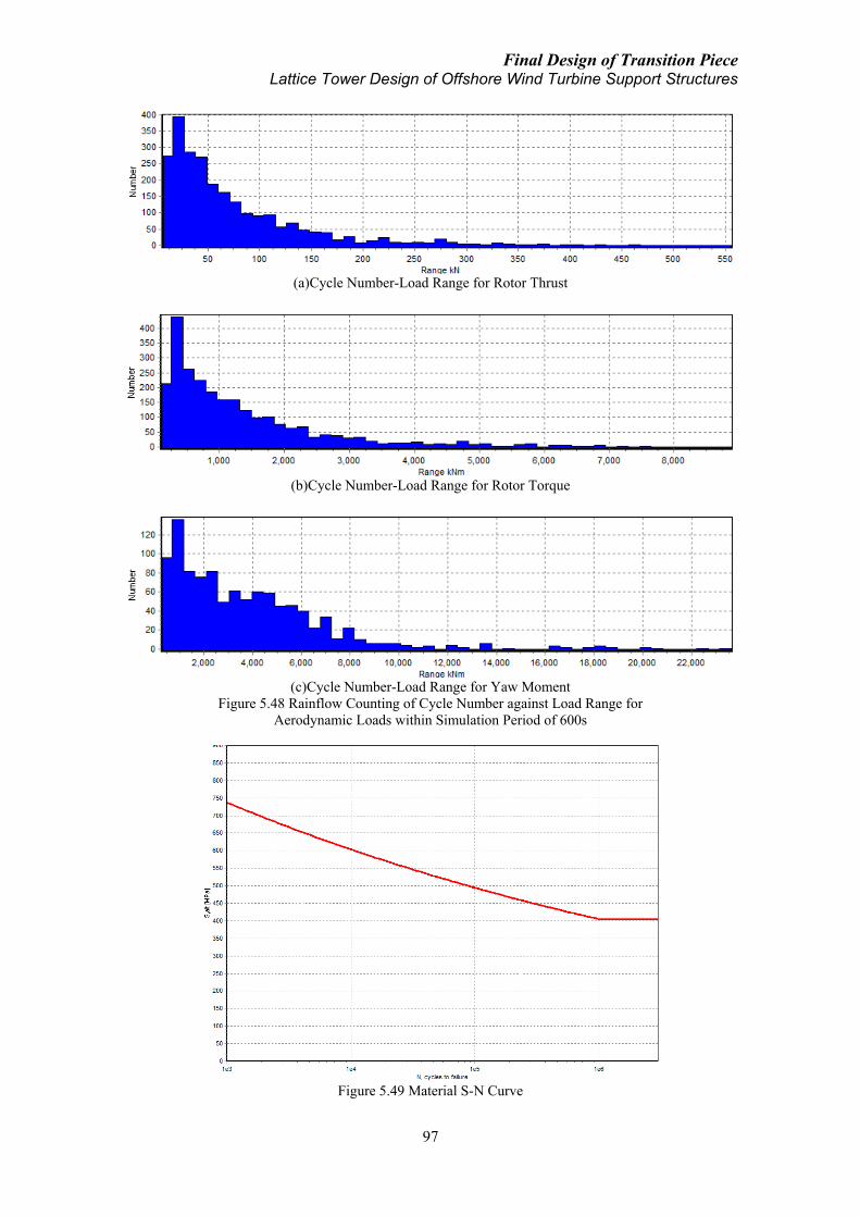
Final Design of Transition Piece Lattice Tower Design of Offshore Wind Turbine Support Structures
97
(a)Cycle Number-Load Range for Rotor Thrust
(b)Cycle Number-Load Range for Rotor Torque
(c)Cycle Number-Load Range for Yaw Moment
Figure 5.48 Rainflow Counting of Cycle Number against Load Range for
Aerodynamic Loads within Simulation Period of 600s
Figure 5.49 Material S-N Curve

Final Design of Transition Piece Lattice Tower Design of Offshore Wind Turbine Support Structures
98
Previous analysis results show that under different load cases, time series of stress
condition at critical stress regions behave in different patterns. Stress condition is in
general in phase with the external load trend but magnitude and frequency of stress
condition under each load case at critical stress zone is specific. According to the above
S-N curve, stress range below 400MPa does not trigger challenge for fatigue protection.
Fatigue damage and life time prediction under various load cases is summarized in
below Table 5.8.
Table 5.8 Fatigue Life Prediction under Various Load Cases at Critical Structural Stress Region
Load Case Stress Range at Critical Structural
Region (MPa)
Predicted Life Time
(Cycles)
Damage per
Cycle
Aero Loads 20-250 1.00E+30 0
Aero Loads
with Yaw 0-550 1.25 E+04 7.99E-05
Aero & Hydro
Loads 20-250 1.00E+30 0
Aero, Hydro
with Yaw 20-400 1.00E+30 0
5.8 Manufacturing
As for manufacturing of the transition piece, a major challenge could be casting of the
truncated cone component. In the original design, 200mm wall thickness appears to be
relatively significant, which makes it not convenient for easy manufacturing process
such as rolling. Truss components could be manufactured by means of standard steel
pipe process whereas welding of the supporting truss components and their connection
with the cone component as well as the lower lattice support structure is another critical
issue during the manufacturing process. Casting process might appear expensive in the
early phase of development but cost reduction could be achieved when future market is
welcoming mass production.
5.9 Conclusion
In this chapter an optimized transition piece design model is proposed with sufficient
analysis under various load conditions as well as fatigue aspect. This new design is of
less weight and thus lower material cost than the previous analysis models in Chapter 4
but its structural performance under all load cases surpass that of the preliminary
analysis models. Behavior of this optimized design under various load cases is
summarized in Table 5.7. Torque and yaw moment are among the most important loads
and hydrodynamic influence from the support structure affects the load bearing pattern
of the transition piece to a significant degree.
Cone thickness of this optimized design is found to be critical for structural load bearing
capacity, especially under the yaw moment load. This parameter comes out as a
compromise between the structural strength and the cost of production. A more compact
design applying a smaller thickness is discussed in Para. 5.6. Structural behavior of the
compact design is less sound than the original one but cost reduction could be possibly
achieved by combination of both design characteristics. Fatigue failure is a challenge
under the aerodynamic and hydrodynamic loads. Structural material properties and the
characteristics of external loads have dominating effects of structural fatigue life. When
utilization of an advanced material type is not possible, regular maintenance could be
able to help to an extent.

Conclusion and Recommendation Lattice Tower Design of Offshore Wind Turbine Support Structures
99
6 CONCLUSION AND RECOMMENDATION
6.1 Conclusion
In context of global environment change and increasing deficiency of conventional
energy sources, offshore wind industry is progressively developing with a promising
future even seen from now. Under this background, prevention of failure and
optimization of input cost remain challenges for further mass production of offshore
wind turbines in future. Support structure of offshore wind turbine contributes to a
significant proportion among the total input and also relates closely to the safety of the
turbine’s operation and thus is the main interest of this thesis.
Conventional support structures like monopile, tripod and concrete block for foundation
and monotower for turbine support have been seen in industrial practice in relatively
shallow water up to present with certain amount of experience and knowledge. However,
as future industry challenges deeper sea, lattice structure could become a sound solution
as wind turbine support structure because of its robustness in structural strength and
efficiency in cost reduction. Existing projects employing lattice structure as wind
turbine foundation in water depth of 30m to 50m can be regarded as a prediction for
future trend.
This thesis work is based on experience learnt from existing hybrid offshore wind
turbine support structures and further proposes a full lattice concept used as both
foundation and tower for future industrial application. Under this concept, transition
piece which connects a full lattice support structure and the turbine rotor nacelle
assembly becomes an important aspect which deserves detailed consideration and
analysis second to none. Existing research and practice sees a lack of study of this
transition piece concept and in this thesis the critical subject is investigated with much
effort.
After introduction of existing hybrid support structure consisting of the lattice structure
and transition piece components, a conceptual model of transition piece is built which
takes into consideration of various aspects including its geometrical requirement,
function requirement (power cable and yaw) as well as mechanical connection
requirement. A mechanical model of the transition piece concept is established
depicting its boundary relation with the lattice support structure and various
aerodynamic and hydrodynamic loads it is subjected to. Preliminary design process
analyzes two different transition piece concepts, namely, frame-cylinder and cone-strut,
mostly based on existing hybrid support structure experience in a comparative manner.
Comparative load analysis of the two concepts by means of finite element analysis
technique shows similar structural performance of these two concepts which are at close
dimension and weight but different structural forms.
A new design by experience of numerical analysis learnt from the preliminary design
models which considers more practical conditions including suitability of connection
with a lattice support structure is finalized in the final design process. This new design
is slightly reduced in weight compared with preliminary concepts but has much better
optimized structural behavior under load analysis scenarios. Response of this new
transition piece design under various load cases is carefully investigated in addition to
briefly considered fatigue and manufacturing aspects. A relatively more compact

Conclusion and Recommendation Lattice Tower Design of Offshore Wind Turbine Support Structures
100
version of this new design is also discussed which provides information for further
optimization and cost reduction strategy. General comparison of the two preliminary
and two final concepts is given in table below.
Table 6.1 Comparison of Various Transition Piece Concepts
Transition Piece Concept
Preliminary Concept Final Concept
Frame-cylinder Cone-strut 0.2m
thickness
0.15m
thickness
Dimension
6m height
6m×6m base
refer to
Table 4.2
6m height
6m×6m base
refer to
Table 4.3
3m height
4m×4m base
refer to
Table 5.2
3m height
4m×4m base
refer to
Table 5.1
Weight (tons) 118 140 95 75
Maximum stress under yaw load(1) 1.26 1.32 1 1.47
refer to Table 4.10 refer to Table 5.7
Maximum stress under combined
hydro-aero load with yaw motion(2)
1 1.72
refer to Table 5.7 (1), (2) Normalized by stress condition of 0.2m thickness final concept model.
6.2 Recommendation
In this thesis, analysis of lattice support structure is provided to an extent and the more
extensive attention is placed on design and analysis of the transition piece. Structural
analysis result of varying lattice designs can be used as reference for relevant
application. Conceptual model of transition piece which takes into consideration of
multiple requirements and mechanical model including boundary condition and load
condition have covered the principal and critical aspects for transition piece modeling,
which can be referred to with reasonable amount of adequacy. Nevertheless, not all
miscellaneous aspects are included and in fact for practical model computation purpose,
they should rather not be.
Preliminary design models are from experience of hybrid support structure and the
transition piece concepts are more suitable for this type of support structure. On the
other hand, final design model is tailored for a full lattice support structure concept
which however remains as a conceptual proposal so far without practical experience.
Analysis of the final design transition piece model is majorly focusing on the less
compact design. Cost reduction can be further achieved through regional redesign
according to more compact design parameters but this should be dealt with carefully.
The applied boundary condition and load cases in combination of various aerodynamic
load and hydrodynamic load conditions are for the proposed models in this thesis and
not designed for any specific project. Design of an offshore wind turbine or a wind farm
should always investigate its site-specific topographical, meteorological and sea state
conditions to determine the relevant aerodynamic and hydrodynamic loads for support
structure’s ultimate and fatigue analysis.
Finally, this thesis work endeavors to provide solution and reference for future relevant
research or practical purpose at the maximum capacity within its scope. Due to physical
and temporal limitations, further verification and correction will be very much
appreciated from interested readers.

Reference Lattice Tower Design of Offshore Wind Turbine Support Structures
101
REFERENCE
[1]Jespersen, KD, 1991, “Vindeby-The First Offshore Wind Farm in the Danish Wind
Power Programme”, Proceedings Windpower.
[2]Alexandra Bech Gjørv Oil & Energy, 2006-05-24, “Hywind Floating Wind Power
Production”.
[3]Hau, E., 2006, Wind Turbines: Fundamentals, Technologies, Application, Economics.
Springer-Verlag, Berlin Heidelberg.
[4]Sinning, F., 2001, “Fachwerktürme für Windkraftanlagen die bessere Wahl”, im
Auftrag von Seeba-Energiesysteme GmbH, Stemwede.
[5]http://www.owectower.no.
[6]Talisman Energy, “Beatrice Wind Farm Demonstrator Project Scoping Report”,
http://www.beatricewind.co.uk.
[7]Deutsche Offshore-Testfeld und Infrastruktur GmbH & Co.KG, 2011, “Alpha
Ventus Fact Sheet”, http://www.alpha-ventus.de.
[8]Seidel, M., 2007, “Jacket substructures for the REpower 5M wind turbine”,
Conference Proceedings European Offshore Wind 2007, Berlin.
[9]Naveen Kumar Vemula, et al, 2010, “UpWind_WP4_D4.2.5_Design solution for the
Upwind reference offshore support structure”, Rambøll, Esbjerk, Denmark.
[10]Vorpahl, F., Kaufer, D., 2010, “Description of a basic model of the „Upwind
reference jacket‟ for code comparison in the OC4 project under IEA Wind Annex
XXX”, Fraunhofer Institute for Wind Energy and Energy System Technology (IWES),
Bremerhaven, Germany.
[11]WeserWind Offshore Construction Georgsmarienhütte, http://www.weserwind.de.
[12]http://www.vestas.com.
[13]European Wind Energy Association (EWEA), “Offshore Support Structure”,
http://www.wind-energy-the-facts.org.
[14]http://www.abb.no.
[15]ABB, 2011, “Submarine Power Cables: Cables for offshore wind farms and
platforms”, http://www.abb.no.
[16]ABB, 2006, “HVDC Light®
Cables”, http://www.abb.com/cables.
[17]ABB, 2010, “XLPE Submarine Cable Systems”, http://www.abb.com/cables.
[18]Bilfinger Berger, Ingenieurbau GmbH, “Offshore Wind Farm Alpha Ventus
Transformer Station”.
[19]http://en.wikipedia.org.
[20]Corrigan, R.D., Viterna, L.A., 1981, Free Yaw Performance of the MOD-0 Large
Horizontal Axis 100 kW Wind Turbine, Cleveland: Lewis Research Center, 44135,
Ohio.
[21]Huß, G., 1993, Anlagentechnisches Meßprogramm an derWindkraftanlageWKA-60
auf Helgoland, BMFT report 0328508D.
[22]Astron Overseas Enterprise, “Slewing Bearing for Wind Turbine”.
[23]Jonkman, J., Butterfield, S., Musial, W., Scott, G., 2009, “Definition of a 5-MW
Reference Wind Turbine for Offshore System Development”, Technical Report
NREL/TP-500-38060.
[24]Johnson, W., 1994, Helicopter Theory, Princeton University Press, Princeton, USA.
[25]Morison, J. R., O'Brien, M. P., Johnson, J. W., Schaaf, S. A., 1950, “The Force
Exerted by Surface Waves on Piles”, Petroleum Transactions (American Institute of
Mining Engineers), 189, pp. 149–154.
Reference Lattice Tower Design of Offshore Wind Turbine Support Structures
102
[26]Peeters, J., Vandepitte, D., Sas, P., 2006, “Structural analysis of a wind turbine and
its drive train using the flexible multibody simulation technique”, Proceedings of ISMA.
[27]RPP Rijs.., 1990, “Blade Element Theory for Performance Analysis of Slow
Running Wind Turbines”, Wind Engineering.
[28]http://www.simulia.com/products/abaqus_fea.
[29]http://www.risoe.dtu.dk.
[30]BVG Associates, The Crown Estate, “A Guide to an Offshore Wind Farm”.
[31]Abaqus/CAE User's Manual, http://www.engin.brown.edu:2080/v6.10/index.
[32]von Mises, R., 1913, Mechanik der festen Körper im plastisch deformablen Zustand,
Göttin. Nachr. Math. Phys., vol. 1, pp. 582–592.
[33]Frohboese, P., Schmuck, C., 2010, “Thrust Coefficients used for Estimation of
Wake Effects for Fatigue Load Calculation”, European Wind Energy Conference 2010,
Warsaw, Poland.
[34]International Electrotechnical Commission, 2007, “Wind turbines Part 1: Design
requirements”, IEC 61400-1, Edition 3.0, 2005-08.
[35]Gumbel, E.J., 1958, Statistices of Extremes, Columbia Uni. Press, p. 73.
[36]Cramer, H., 1966, On the Intersections Between Trajectories of a Normal
Stationary Stochastic Process and a High Level, Arkiv for Matematik, V.6, pp. 337-349.
[37]Airy, G. B., “Tides and Waves,” In Rose, H. J. et al., Encyclopaedia Metropolitana
Mixed Sciences 3 1817–1845.
[38]Hasselmann K. et al., 1973, Measurements of wind-wave growth and swell decay
during the Joint North Sea Wave Project (JONSWAP), 'Ergnzungsheft zur Deutschen
Hydrographischen Zeitschrift Reihe, A(8) (Nr. 12), p.95.
[39]W. Schutz, 1996, A history of fatigue. Engineering Fracture Mechanics 54: 263-
300. DOI.

Appendix I Lattice Tower Design of Offshore Wind Turbine Support Structures
103
APPENDIX I
Application of HVDC and XLPE Power Transmission Cable on Offshore Wind Farm
Projects [15]
I.1 DC cable offshore applications
−− DolWin1 Offshore Wind Project, Germany
2x74 km, 800 MW, +/- 320 kV HVDC Light submarine power cables with Cu
conductor and 2x90 km, 800 MW, +/- 320 kV HVDC Light underground cables with Al
conductor. 7,5 km, 200 MW, 155 kV AC submarine cable with Cu conductors and
integrated optical fiber cable.
−− BorWin1 Offshore Wind Project, Germany
2x125 km, 400 MW, +/-150 kV HVDC Light submarine power cables with Cu
conductor and 2x75 km, 400 MW, +/-150 kV HVDC Light underground cables with Al
conductor.
I.2 AC cable offshore applications
−− Thornton Bank Offshore Wind Farm Phase 2 & 3, Belgium
38 km, 150 MW, 150 kV shore connection power cable with Al conductors and
integrated optical fiber cable and 26 + 34 km, 33 kV inter-turbine cables with Al and Cu
conductors and integrated optical fiber cable.
−− Nordsee Ost Offshore Wind Farm, Germany
63 km, 33 kV inter-turbine cables with Cu conductor and integrated optical fiber cable.
−− Thornton Bank Offshore Wind Farm, Belgium
38 km, 150 MW, 150 kV shore connection power cable with Al conductors and
integrated optical fiber cable and 4 km, 33 kV inter-turbine cables with Al conductors
and integrated optical fiber cable.
−− Prinses Amaliawindpark (Q7), the Netherlands
28 km, 120 MW, 170 kV shore connection power cable with Cu conductors and
integrated optical fiber cables and 40 km, 24 kV inter-turbine cables with Al and Cu
conductors and integrated optical fiber cable.
−− Lillgrund Offshore Wind Farm, Sweden
33 km, 110 MW, 145 kV shore connection power cable and 36 kV inter-turbine cables
with Cu conductors and integrated optical fibers.

Appendix I Lattice Tower Design of Offshore Wind Turbine Support Structures
104
−− Burbo Banks Offshore Wind Farm, UK
40 km, 90 MW, 36 kV inter-turbine and shore connection power cables with Cu
conductors.
−− Yttre Stengrund Offshore Wind Farm, Sweden
22 km, 10 MW, 24 kV inter-turbine and shore connection power cables with Al
conductors and integrated optical fibers.
−− Utgrunden Offshore Wind Farm, Sweden
11 km, 10 MW, 24 kV inter-turbine and shore connection power cables with Al
conductors and integrated optical fiber cable.
−− Samsö Offshore Wind Farm, Denmark
7.5 km, 20 MW, 36 kV inter-turbine and shore connection power cable with Cu
conductors integrated optical fiber cable.
−− Nysted Offshore Wind Farm, Denmark
55 km, 165 MW, 36 kV inter-turbine power cables with Al- and Cu conductors and
integrated optical fiber cable.
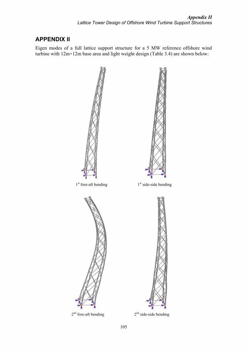
Appendix II Lattice Tower Design of Offshore Wind Turbine Support Structures
105
APPENDIX II
Eigen modes of a full lattice support structure for a 5 MW reference offshore wind
turbine with 12m×12m base area and light weight design (Table 3.4) are shown below:
1st fore-aft bending 1st side-side bending
2nd fore-aft bending 2nd side-side bending
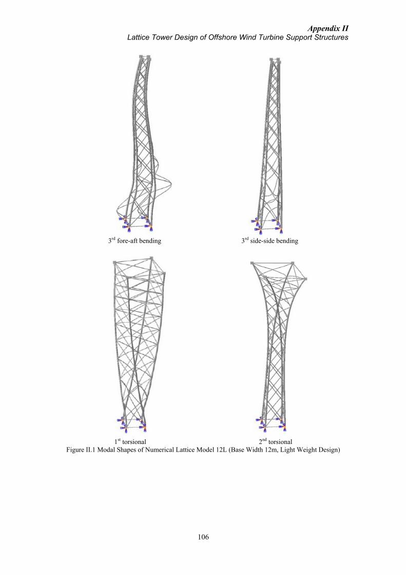
Appendix II Lattice Tower Design of Offshore Wind Turbine Support Structures
106
3rd fore-aft bending 3rd side-side bending
1st torsional 2nd torsional
Figure II.1 Modal Shapes of Numerical Lattice Model 12L (Base Width 12m, Light Weight Design)

Appendix III Lattice Tower Design of Offshore Wind Turbine Support Structures
107
APPENDIX III
1st Mode of Frame-cylinder TP 1st Mode of Cone-strut TP
2nd Mode of Frame-cylinder TP 2nd Mode of Cone-strut TP
3rd Mode of Frame-cylinder TP 3rd Mode of Cone-strut TP
Figure III.1 Eigen Models of Transition Piece (Transparent Model Indicates the Original Undeformed
Model and Colour Contour Indicates the Magnitude of Structural Deflection)

Appendix IV Lattice Tower Design of Offshore Wind Turbine Support Structures
108
APPENDIX IV
If structural stress is assumed to be related to the load, the stress will thus progressively
increase with the increasing load. The strength of a structure can therefore be defined in
terms of an ultimate load that leads to failure.
For the aerodynamic loads on wind turbines, the loads depend on the instantaneously
changing wind condition including the mean wind speed, wind direction, the turbulence
intensity, etc. In order to determine a suitable characteristic load for structural strength
assessment, it is necessary to analyze the extreme values of the aerodynamic load on a
statistical basis.
IEC 61400 [34] provides method of statistical extrapolation of aerodynamic loads for
ultimate strength analysis for wind turbines based on probabilistic methods by Gumbel
& Cramer [35, 36]. Using this method, wind speeds around the rated and cut-out points
should be paid attention, along with the adequacy and resolution of the number of wind
speed bins.
Figure IV.1 Exceedance Probability for Largest Out-of-plane Blade Bending Load in 10-minute
(Normalized by Mean Bending Load at Rated Wind Speed) (Source: IEC 1257/05)
Applying the method, the figure above shows the computed long-term exceedance
probability of a blade bending load normalized by the mean blade bending load at rated
wind speed (bold line). The dash line refers to the largest computed blade bending load
for all the simulations at the different mean wind speeds between cut-in and cut-out.
The 50-year extreme bending load thus exceeds the maximum simulated load. Based on
this thought, the aerodynamic loads used in this thesis based on normal turbulent wind
model at mean wind speed of 24m/s, close to the cut-out speed, are assumed to
approximate a relatively extreme load case. A specific analysis of the long-term load
exceedance probability should be performed in the realistic project.

Appendix V Lattice Tower Design of Offshore Wind Turbine Support Structures
109
APPENDIX V
(a.1)Flow Velocity at Sea Surface (Z=-30)
(a.2)Flow Velocity at 10m Water Depth (Z=-20)
(a.3)Flow Velocity at 20m Water Depth (Z=-10)
(a.4)Flow Velocity at 29m Water Depth (Seabed Z=-1)
(b.1)Flow Acceleration at Sea Surface (Z=-30)
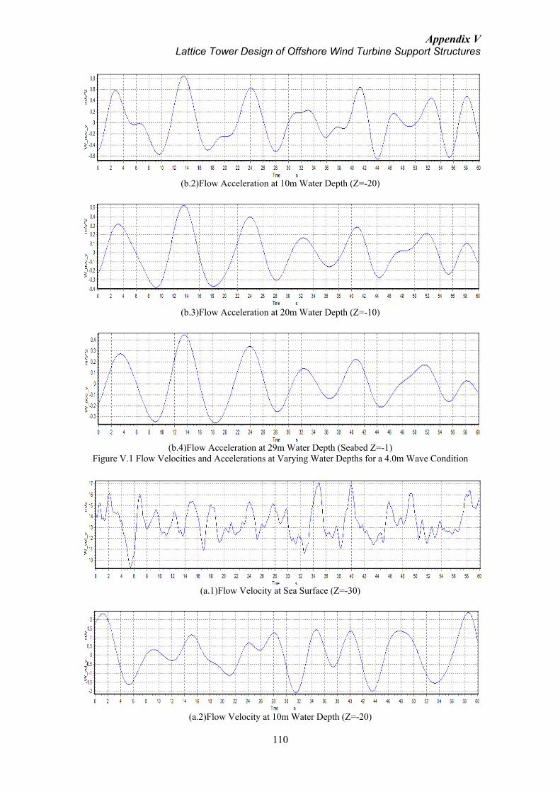
Appendix V Lattice Tower Design of Offshore Wind Turbine Support Structures
110
(b.2)Flow Acceleration at 10m Water Depth (Z=-20)
(b.3)Flow Acceleration at 20m Water Depth (Z=-10)
(b.4)Flow Acceleration at 29m Water Depth (Seabed Z=-1)
Figure V.1 Flow Velocities and Accelerations at Varying Water Depths for a 4.0m Wave Condition
(a.1)Flow Velocity at Sea Surface (Z=-30)
(a.2)Flow Velocity at 10m Water Depth (Z=-20)
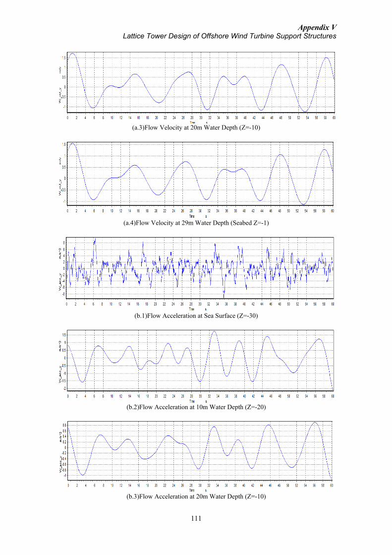
Appendix V Lattice Tower Design of Offshore Wind Turbine Support Structures
111
(a.3)Flow Velocity at 20m Water Depth (Z=-10)
(a.4)Flow Velocity at 29m Water Depth (Seabed Z=-1)
(b.1)Flow Acceleration at Sea Surface (Z=-30)
(b.2)Flow Acceleration at 10m Water Depth (Z=-20)
(b.3)Flow Acceleration at 20m Water Depth (Z=-10)

Appendix V Lattice Tower Design of Offshore Wind Turbine Support Structures
112
(b.4)Flow Acceleration at 29m Water Depth (Seabed Z=-1)
Figure V.2 Flow Velocities and Accelerations at Varying Water Depths for a 10m Wave Condition
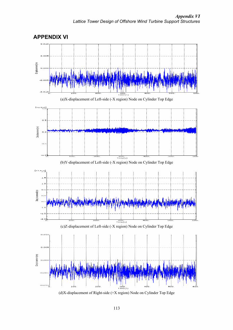
Appendix VI Lattice Tower Design of Offshore Wind Turbine Support Structures
113
APPENDIX VI
(a)X-displacement of Left-side (-X region) Node on Cylinder Top Edge
(b)Y-displacement of Left-side (-X region) Node on Cylinder Top Edge
(c)Z-displacement of Left-side (-X region) Node on Cylinder Top Edge
(d)X-displacement of Right-side (+X region) Node on Cylinder Top Edge

Appendix VI Lattice Tower Design of Offshore Wind Turbine Support Structures
114
(e)Y-displacement of Right-side (+X region) Node on Cylinder Top Edge
(f)Z-displacement of Right-side (+X region) Node on Cylinder Top Edge
Figure VI.1 Deflection of Cylinder Top Edge Points of the Frame-cylinder TP under Rotor Torque
(a)X-displacement of Left-side (-X region) Node on Cone Edge
(b)Y-displacement of Left-side (-X region) Node on Cone Edge

Appendix VI Lattice Tower Design of Offshore Wind Turbine Support Structures
115
(c)Z-displacement of Left-side (-X region) Node on Cone Edge
(d)X-displacement of Right-side (+X region) Node on Cone Edge
(e)Y-displacement of Right-side (+X region) Node on Cone Edge
(f)Z-displacement of Right-side (+X region) Node on Cone Edge
Figure VI.2 Deflection of Cone Top Edge Points in the Cone-strut TP under Rotor Torque
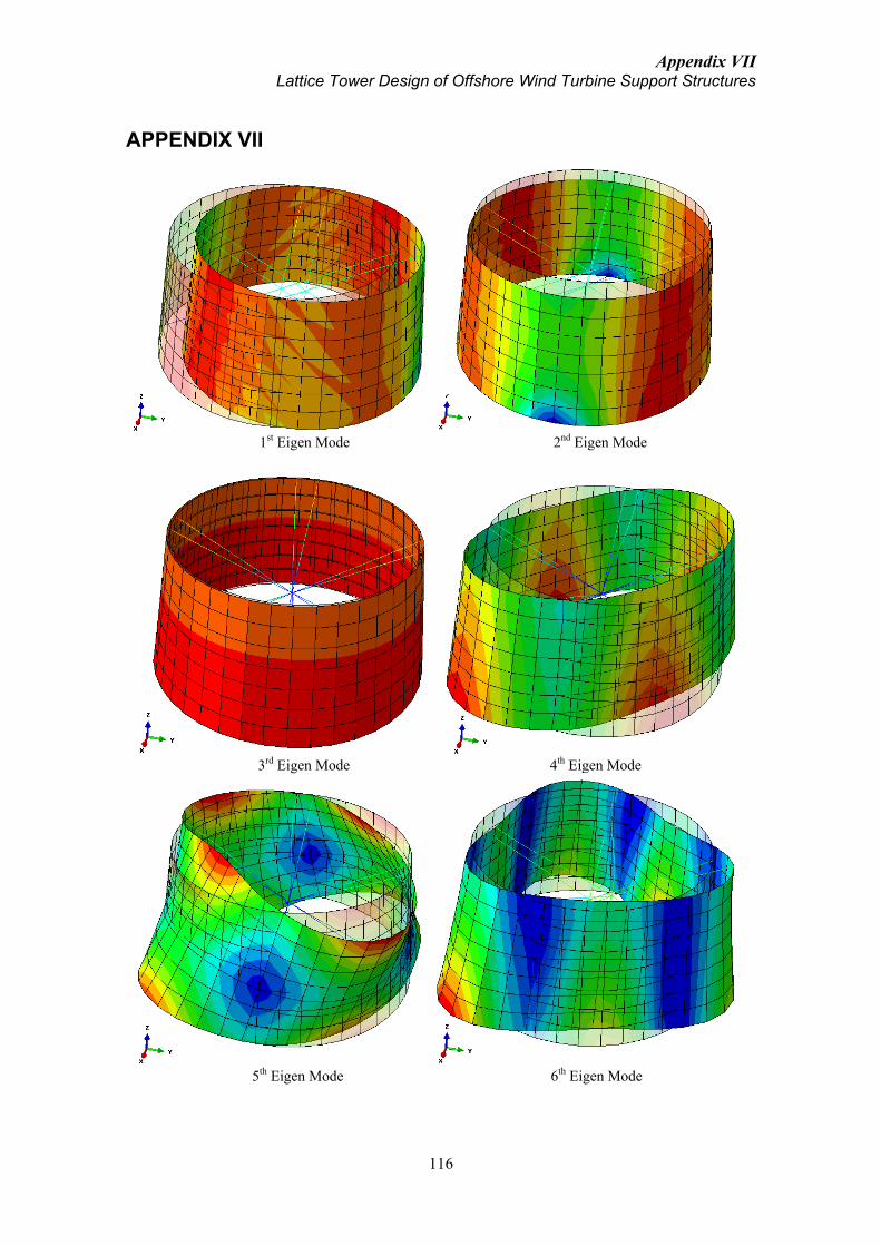
Appendix VII Lattice Tower Design of Offshore Wind Turbine Support Structures
116
APPENDIX VII
1st Eigen Mode 2nd Eigen Mode
3rd Eigen Mode 4th Eigen Mode
5th Eigen Mode 6th Eigen Mode

Appendix VII Lattice Tower Design of Offshore Wind Turbine Support Structures
117
7th Eigen Mode 8th Eigen Mode
9th Eigen Mode 10th Eigen Mode
11th Eigen Mode 12th Eigen Mode
Figure VII.1 First 12 Eigen Modes of Transition Piece of 3m-high and 0.2m-thick (Transparent Model is
the Original Undeformed One and Colour Contours Indicate Degree of Deformation)