Latitude 3520 Service Manual
118
Latitude 3520 Service Manual Regulatory Model: P108F Regulatory Type: P108F001/P108F002 2021 Rev. A00
Transcript of Latitude 3520 Service Manual

Latitude 3520Service Manual
Regulatory Model: P108FRegulatory Type: P108F001/P108F0022021Rev. A00

Notes, cautions, and warnings
NOTE: A NOTE indicates important information that helps you make better use of your product.
CAUTION: A CAUTION indicates either potential damage to hardware or loss of data and tells you how to avoid
the problem.
WARNING: A WARNING indicates a potential for property damage, personal injury, or death.
© 2021 Dell Inc. or its subsidiaries. All rights reserved. Dell, EMC, and other trademarks are trademarks of Dell Inc. or its subsidiaries. Othertrademarks may be trademarks of their respective owners.

Chapter 1: Working inside your computer...................................................................................... 7Safety instructions.............................................................................................................................................................. 7
Before working inside your computer....................................................................................................................... 7Entering Service Mode................................................................................................................................................. 8Exiting Service Mode.................................................................................................................................................... 8Safety precautions........................................................................................................................................................ 8Electrostatic discharge—ESD protection............................................................................................................... 9ESD field service kit ..................................................................................................................................................... 9Transporting sensitive components.........................................................................................................................10After working inside your computer........................................................................................................................ 10
Chapter 2: Removing and installing components...........................................................................11Recommended tools...........................................................................................................................................................11Screw List............................................................................................................................................................................ 12Major components of your system................................................................................................................................ 14MicroSD-card......................................................................................................................................................................15
Removing the microSD-card..................................................................................................................................... 15Installing the MicroSD-card....................................................................................................................................... 16
SIM card tray...................................................................................................................................................................... 16Removing the SIM card tray......................................................................................................................................16Installing the SIM card tray........................................................................................................................................ 17
Base cover........................................................................................................................................................................... 18Removing the base cover...........................................................................................................................................18Installing the base cover............................................................................................................................................ 20
Battery cable....................................................................................................................................................................... 21Removing the battery cable...................................................................................................................................... 21
Installing the battery cable........................................................................................................................................22Battery................................................................................................................................................................................. 23
Lithium-ion battery precautions...............................................................................................................................23Removing the 3-cell battery..................................................................................................................................... 24Installing the 3-cell battery....................................................................................................................................... 24Removing the 4-cell battery..................................................................................................................................... 25Installing the 4-cell battery....................................................................................................................................... 26
Memory module................................................................................................................................................................. 27Removing the memory module.................................................................................................................................27Installing the memory module...................................................................................................................................28
M.2 solid-state drive thermal plate...............................................................................................................................30Replacing the M.2 solid-state drive thermal plate.............................................................................................. 30
M.2 solid-state drive conversion bracket.....................................................................................................................31Removing the M.2 solid-state drive conversion bracket....................................................................................31Installing the M.2 solid-state drive conversion bracket...................................................................................... 31
M.2 solid-state drive.........................................................................................................................................................32Removing the M.2 2230 solid-state drive............................................................................................................. 32Installing the M.2 2230 solid-state drive............................................................................................................... 33
Contents
Contents 3

Removing the M.2 2280 solid-state drive............................................................................................................. 34Installing the M.2 2280 solid-state drive............................................................................................................... 34
Hard-disk drive...................................................................................................................................................................35Removing the hard-disk drive.................................................................................................................................. 35Removing the hard-disk drive bracket................................................................................................................... 36Installing the hard-disk drive bracket..................................................................................................................... 37Installing the hard-disk drive.....................................................................................................................................38
WLAN card..........................................................................................................................................................................39Removing the WLAN card.........................................................................................................................................39Installing the WLAN card...........................................................................................................................................40
WWAN card........................................................................................................................................................................ 42Removing the WWAN card....................................................................................................................................... 42Installing the WWAN card......................................................................................................................................... 43
I/O cable..............................................................................................................................................................................44Removing the I/O cable.............................................................................................................................................44Installing the I/O cable...............................................................................................................................................45
Display assembly................................................................................................................................................................46Removing the display assembly............................................................................................................................... 46Installing the display assembly..................................................................................................................................49
System fan...........................................................................................................................................................................51Removing the system fan.......................................................................................................................................... 51Installing the system fan.............................................................................................................................................51
Heatsink assembly.............................................................................................................................................................52Removing the heatsink assembly............................................................................................................................ 52Installing the heatsink assembly...............................................................................................................................53
Power adapter port.......................................................................................................................................................... 54Removing the power adapter port.......................................................................................................................... 54Installing the power adapter port............................................................................................................................ 55
Coin-cell battery................................................................................................................................................................56Removing the coin-cell battery................................................................................................................................56Installing the coin-cell battery.................................................................................................................................. 57
USB cable............................................................................................................................................................................58Removing the USB cable...........................................................................................................................................58Installing the USB cable.............................................................................................................................................59
Ethernet port......................................................................................................................................................................60Removing the ethernet port.....................................................................................................................................60Installing the ethernet port........................................................................................................................................ 61
I/O board.............................................................................................................................................................................62Removing the I/O board............................................................................................................................................62Installing the I/O board.............................................................................................................................................. 63
Power-button board......................................................................................................................................................... 64Removing the power-button board.........................................................................................................................64Installing the power-button board...........................................................................................................................64
System board..................................................................................................................................................................... 65Removing the system board.....................................................................................................................................65Installing the system board....................................................................................................................................... 68
Speakers.............................................................................................................................................................................. 72Removing the speaker................................................................................................................................................ 72Installing the speaker.................................................................................................................................................. 72
Touchpad ............................................................................................................................................................................73
4 Contents

Removing the touchpad.............................................................................................................................................73Installing the touchpad............................................................................................................................................... 74
WWAN I/O board .............................................................................................................................................................75Removing the WWAN I/O board............................................................................................................................. 75Installing the WWAN I/O board............................................................................................................................... 76
Palmrest assembly.............................................................................................................................................................77Removing the palmrest assembly............................................................................................................................ 77Installing the palmrest assembly.............................................................................................................................. 78
Display bezel.......................................................................................................................................................................80Removing the display bezel...................................................................................................................................... 80Installing the display bezel..........................................................................................................................................81
Display panel....................................................................................................................................................................... 82Removing the display panel.......................................................................................................................................82Installing the display panel.........................................................................................................................................85
Camera.................................................................................................................................................................................88Removing the camera ............................................................................................................................................... 88Installing the camera ................................................................................................................................................. 88
Display cable....................................................................................................................................................................... 89Removing the display cable ..................................................................................................................................... 89Installing the display cable ....................................................................................................................................... 90
Display back-cover............................................................................................................................................................92Removing the display back-cover........................................................................................................................... 92Installing the display back-cover..............................................................................................................................92
Chapter 3: Drivers and downloads............................................................................................... 94
Chapter 4: System setup.............................................................................................................95Boot menu...........................................................................................................................................................................95Boot Sequence.................................................................................................................................................................. 95Navigation keys..................................................................................................................................................................96System setup options.......................................................................................................................................................96Updating the BIOS in Windows ...................................................................................................................................106
Updating BIOS on systems with BitLocker enabled..........................................................................................106Updating your system BIOS using a USB flash drive........................................................................................ 106
System and setup password......................................................................................................................................... 107Assigning a system setup password......................................................................................................................107Deleting or changing an existing system setup password............................................................................... 108
Chapter 5: Troubleshooting....................................................................................................... 109Built-in self-test (BIST)................................................................................................................................................. 109LCD Built-in Self Test (BIST)....................................................................................................................................... 109Dell SupportAssist Pre-boot System Performance Check diagnostics...............................................................110
Running the SupportAssist Pre-Boot System Performance Check............................................................... 110Diagnostic LED behavior..................................................................................................................................................111Diagnostic error messages............................................................................................................................................. 112System error messages...................................................................................................................................................115Recovering the operating system................................................................................................................................ 115Real-Time Clock (RTC Reset)....................................................................................................................................... 116Flashing the BIOS............................................................................................................................................................. 116
Contents 5

Backup media and recovery options............................................................................................................................ 116WiFi power cycle.............................................................................................................................................................. 116Flea power release............................................................................................................................................................117
Chapter 6: Getting help and contacting Dell............................................................................... 118
6 Contents

Working inside your computer
Topics:
• Safety instructions
Safety instructions
Prerequisites
Use the following safety guidelines to protect your computer from potential damage and to ensure your personal safety. Unlessotherwise noted, each procedure included in this document assumes that the following conditions exist:● You have read the safety information that shipped with your computer.● A component can be replaced or, if purchased separately, installed by performing the removal procedure in reverse order.
About this task
WARNING: Before working inside your computer, read the safety information that shipped with your computer.
For additional safety best practices information, see the Regulatory Compliance Homepage
CAUTION: Many repairs may only be done by a certified service technician. You should only perform
troubleshooting and simple repairs as authorized in your product documentation, or as directed by the online or
telephone service and support team. Damage due to servicing that is not authorized by Dell is not covered by
your warranty. Read and follow the safety instructions that came with the product.
CAUTION: To avoid electrostatic discharge, ground yourself by using a wrist grounding strap or by periodically
touching an unpainted metal surface at the same time as touching a connector on the back of the computer.
CAUTION: Handle components and cards with care. Do not touch the components or contacts on a card. Hold a
card by its edges or by its metal mounting bracket. Hold a component such as a processor by its edges, not by
its pins.
CAUTION: When you disconnect a cable, pull on its connector or on its pull-tab, not on the cable itself. Some
cables have connectors with locking tabs; if you are disconnecting this type of cable, press in on the locking
tabs before you disconnect the cable. As you pull connectors apart, keep them evenly aligned to avoid bending
any connector pins. Also, before you connect a cable, ensure that both connectors are correctly oriented and
aligned.
NOTE: Disconnect all power sources before opening the computer cover or panels. After you finish working inside the
computer, replace all covers, panels, and screws before connecting to the power source.
NOTE: The color of your computer and certain components may appear differently than shown in this document.
Before working inside your computer
Steps
1. Save and close all open files and exit all open applications.
2. Shut down your computer. Click Start > Power > Shut down.
NOTE: If you are using a different operating system, see the documentation of your operating system for shut-down
instructions.
1
Working inside your computer 7
3. Disconnect your computer and all attached devices from their electrical outlets.
4. Disconnect all attached network devices and peripherals, such as keyboard, mouse, and monitor from your computer.
5. Remove any media card and optical disc from your computer, if applicable.
6. After the computer is unplugged, press and hold the power button for 5 seconds to ground the system board.
CAUTION: Place the computer on a flat, soft, and clean surface to avoid scratches on the display.
7. Place the computer face down.
Entering Service Mode
Service Mode allows users to immediately cut off electricity from the computer and conduct repairs without disconnecting thebattery cable from the system board.
To enter Service Mode:
1. Shut down your computer and disconnect the AC adapter.2. Hold <B> key on the keyboard and press the power button for 3 seconds or until the Dell logo appears on the screen.3. Press any key to continue.
NOTE: If the power adapter has not been disconnected, a message prompting you to remove the AC adapter appears
on the screen. Remove the AC adapter and then press any key to continue the Service Mode procedure.
NOTE: The Service Mode procedure automatically skips the following step if the Owner Tag of the computer is not
set up in advance by the manufacturer.
4. When the ready-to-proceed message appears on the screen, press any key to proceed. The computer emits three shortbeeps and shuts down immediately.
Once the computer shuts down, you may perform the replacement procedures without disconnecting the battery cable fromthe system board.
Exiting Service Mode
Service Mode allows users to immediately cut off electricity from the computer and conduct repairs without disconnecting thebattery cable from the system board.
To exit Service Mode:
1. Connect the AC adapter to the power-adapter port on your computer.2. Press the power button to turn on the computer. Your computer will automatically return to normal functioning mode.
Safety precautions
The safety precautions chapter details the primary steps to be taken before performing any disassembly instructions.
Observe the following safety precautions before you perform any installation or break/fix procedures involving disassembly orreassembly:● Turn off the system and all attached peripherals.● Disconnect the system and all attached peripherals from AC power.● Disconnect all network cables, telephone, and telecommunications lines from the system.● Use an ESD field service kit when working inside any to avoid electrostatic discharge (ESD) damage.● After removing any system component, carefully place the removed component on an anti-static mat.● Wear shoes with non-conductive rubber soles to reduce the chance of getting electrocuted.
Standby power
Dell products with standby power must be unplugged before you open the case. Systems that incorporate standby power areessentially powered while turned off. The internal power enables the system to be remotely turned on (wake on LAN) andsuspended into a sleep mode and has other advanced power management features.
8 Working inside your computer

Unplugging, pressing and holding the power button for 15 seconds should discharge residual power in the system board.
Bonding
Bonding is a method for connecting two or more grounding conductors to the same electrical potential. This is done throughthe use of a field service electrostatic discharge (ESD) kit. When connecting a bonding wire, ensure that it is connected to baremetal and never to a painted or non-metal surface. The wrist strap should be secure and in full contact with your skin, andensure that you remove all jewelry such as watches, bracelets, or rings prior to bonding yourself and the equipment.
Electrostatic discharge—ESD protection
ESD is a major concern when you handle electronic components, especially sensitive components such as expansion cards,processors, memory DIMMs, and system boards. Very slight charges can damage circuits in ways that may not be obvious, suchas intermittent problems or a shortened product life span. As the industry pushes for lower power requirements and increaseddensity, ESD protection is an increasing concern.
Due to the increased density of semiconductors used in recent Dell products, the sensitivity to static damage is now higher thanin previous Dell products. For this reason, some previously approved methods of handling parts are no longer applicable.
Two recognized types of ESD damage are catastrophic and intermittent failures.● Catastrophic – Catastrophic failures represent approximately 20 percent of ESD-related failures. The damage causes
an immediate and complete loss of device functionality. An example of catastrophic failure is a memory DIMM that hasreceived a static shock and immediately generates a "No POST/No Video" symptom with a beep code emitted for missing ornonfunctional memory.
● Intermittent – Intermittent failures represent approximately 80 percent of ESD-related failures. The high rate ofintermittent failures means that most of the time when damage occurs, it is not immediately recognizable. The DIMMreceives a static shock, but the tracing is merely weakened and does not immediately produce outward symptoms related tothe damage. The weakened trace may take weeks or months to melt, and in the meantime may cause degradation of memoryintegrity, intermittent memory errors, etc.
Perform the following steps to prevent ESD damage:● Use a wired ESD wrist strap that is properly grounded. The use of wireless anti-static straps is no longer allowed; they do not
provide adequate protection. Touching the chassis before handling parts does not ensure adequate ESD protection on partswith increased sensitivity to ESD damage.
● Handle all static-sensitive components in a static-safe area. If possible, use anti-static floor pads and workbench pads.● When unpacking a static-sensitive component from its shipping carton, do not remove the component from the anti-static
packing material until you are ready to install the component. Before unwrapping the anti-static packaging, ensure that youdischarge static electricity from your body.
● Before transporting a static-sensitive component, place it in an anti-static container or packaging.
ESD field service kit
The unmonitored Field Service kit is the most commonly used service kit. Each Field Service kit includes three main components:anti-static mat, wrist strap, and bonding wire.
Components of an ESD field service kit
The components of an ESD field service kit are:● Anti-Static Mat – The anti-static mat is dissipative and parts can be placed on it during service procedures. When using an
anti-static mat, your wrist strap should be snug and the bonding wire should be connected to the mat and to any bare metalon the system being worked on. Once deployed properly, service parts can be removed from the ESD bag and placed directlyon the mat. ESD-sensitive items are safe in your hand, on the ESD mat, in the system, or inside a bag.
● Wrist Strap and Bonding Wire – The wrist strap and bonding wire can be either directly connected between your wristand bare metal on the hardware if the ESD mat is not required, or connected to the anti-static mat to protect hardware thatis temporarily placed on the mat. The physical connection of the wrist strap and bonding wire between your skin, the ESDmat, and the hardware is known as bonding. Use only Field Service kits with a wrist strap, mat, and bonding wire. Neveruse wireless wrist straps. Always be aware that the internal wires of a wrist strap are prone to damage from normal wearand tear, and must be checked regularly with a wrist strap tester in order to avoid accidental ESD hardware damage. It isrecommended to test the wrist strap and bonding wire at least once per week.
Working inside your computer 9

● ESD Wrist Strap Tester – The wires inside of an ESD strap are prone to damage over time. When using an unmonitoredkit, it is a best practice to regularly test the strap prior to each service call, and at a minimum, test once per week. Awrist strap tester is the best method for doing this test. If you do not have your own wrist strap tester, check with yourregional office to find out if they have one. To perform the test, plug the wrist-strap's bonding-wire into the tester while it isstrapped to your wrist and push the button to test. A green LED is lit if the test is successful; a red LED is lit and an alarmsounds if the test fails.
● Insulator Elements – It is critical to keep ESD sensitive devices, such as plastic heat sink casings, away from internal partsthat are insulators and often highly charged.
● Working Environment – Before deploying the ESD Field Service kit, assess the situation at the customer location. Forexample, deploying the kit for a server environment is different than for a desktop or portable environment. Servers aretypically installed in a rack within a data center; desktops or portables are typically placed on office desks or cubicles. Alwayslook for a large open flat work area that is free of clutter and large enough to deploy the ESD kit with additional space toaccommodate the type of system that is being repaired. The workspace should also be free of insulators that can cause anESD event. On the work area, insulators such as Styrofoam and other plastics should always be moved at least 12 inches or30 centimeters away from sensitive parts before physically handling any hardware components
● ESD Packaging – All ESD-sensitive devices must be shipped and received in static-safe packaging. Metal, static-shieldedbags are preferred. However, you should always return the damaged part using the same ESD bag and packaging that thenew part arrived in. The ESD bag should be folded over and taped shut and all the same foam packing material should beused in the original box that the new part arrived in. ESD-sensitive devices should be removed from packaging only at anESD-protected work surface, and parts should never be placed on top of the ESD bag because only the inside of the bag isshielded. Always place parts in your hand, on the ESD mat, in the system, or inside an anti-static bag.
● Transporting Sensitive Components – When transporting ESD sensitive components such as replacement parts or partsto be returned to Dell, it is critical to place these parts in anti-static bags for safe transport.
ESD protection summary
It is recommended that all field service technicians use the traditional wired ESD grounding wrist strap and protective anti-staticmat at all times when servicing Dell products. In addition, it is critical that technicians keep sensitive parts separate from allinsulator parts while performing service and that they use anti-static bags for transporting sensitive components.
Transporting sensitive components
When transporting ESD sensitive components such as replacement parts or parts to be returned to Dell, it is critical to placethese parts in anti-static bags for safe transport.
After working inside your computer
About this task
NOTE: Leaving stray or loose screws inside your computer may severely damage your computer.
Steps
1. Replace all screws and ensure that no stray screws remain inside your computer.
2. Connect any external devices, peripherals, or cables you removed before working on your computer.
3. Replace any media cards, discs, or any other parts that you removed before working on your computer.
4. Connect your computer and all attached devices to their electrical outlets.
5. Turn on your computer.
10 Working inside your computer

Removing and installing components
NOTE: The images in this document may differ from your computer depending on the configuration you ordered.
Topics:
• Recommended tools• Screw List• Major components of your system• MicroSD-card• SIM card tray• Base cover• Battery cable• Battery• Memory module• M.2 solid-state drive thermal plate• M.2 solid-state drive conversion bracket• M.2 solid-state drive• Hard-disk drive• WLAN card• WWAN card• I/O cable• Display assembly• System fan• Heatsink assembly• Power adapter port• Coin-cell battery• USB cable• Ethernet port• I/O board• Power-button board• System board• Speakers• Touchpad• WWAN I/O board• Palmrest assembly• Display bezel• Display panel• Camera• Display cable• Display back-cover
Recommended toolsThe procedures in this document may require the following tools:● Phillips #0 screwdriver● Plastic scribe
2
Removing and installing components 11

Screw ListThe following table shows the screw list and the image of the screws.
Table 1. Screw list
Component Screw type Quantity Image
Base cover Captive screws 9
3-cell battery M2x3 3
4-cell battery M2x3 5
M.2 Solid-state drive bracket M2x3 1
M.2 Solid-state drive thermal plate M2x3 1
M.2 Solid-state drive conversion bracket M2x3 2
12 Removing and installing components

Table 1. Screw list
Component Screw type Quantity Image
Hard disk-drive module Captive screws 4
Hard disk-drive M3x3 4
WLAN card M2x3 1
WWAN card M2x3 1
Display hinges M2.5x6
M2.5x4
6
1
System Fan M2x3 2
Heatsink assembly Captive screws 7 (For systemsenabled withdiscrete graphiccard)
4 (For systemsenabled withintegrated graphiccard)
Power adapter port M2x3 1
Ethernet port M2x5 2
I/O board M2x3 2
System board M2x5 2
Touchpad bracket M2.5x2 3
Touchpad module M2x2 4
WWAN I/O board M2x3 2
Hinge bracket M2.5x2.5
M2.5x3
6
2
Removing and installing components 13

Major components of your system
14 Removing and installing components

1. Base cover2. Battery3. Memory module4. WLAN card5. Solid-state drive6. Solid-state drive conversion bracket7. WWAN card8. Power adapter port9. Coin-cell battery10. Touchpad bracket11. System board12. Touchpad13. Computer chassis14. Display assembly15. WWAN I/O board16. I/O board17. System fan18. Heatsink assembly19. Ethernet port20. Power-button board
NOTE: Dell provides a list of components and their part numbers for the original system configuration purchased. These
parts are available according to warranty coverages purchased by the customer. Contact your Dell sales representative for
purchase options.
MicroSD-card
Removing the microSD-card
Prerequisites
1. Follow the procedure in before working inside your computer.
About this task
The following image provides a visual representation of the microSD-card removal procedure.
Removing and installing components 15

Steps
1. Push the microSD-card to eject it from the slot.
2. Remove the microSD-card from the system.
Installing the MicroSD-card
Prerequisites
If you are replacing a component, remove the existing component before performing the installation procedure.
About this task
The following image provides a visual representation of the MicroSD-card installation procedure.
Steps
Insert the microSD-card into its slot until it clicks into place.
Next steps
1. Follow the procedure in after working inside your computer.
SIM card tray
Removing the SIM card tray
Prerequisites
1. Follow the procedure in before working inside your computer.2. Remove the microSD-card.
About this task
NOTE: The following steps are applicable only for 4G LTE enabled systems.
The following image provides a visual representation of the SIM card tray removal procedure.
16 Removing and installing components

Steps
1. Insert the SIM card removal pin into the release hole to release the SIM card tray.
2. Push the pin to disengage the lock, and eject the SIM card tray.
3. Slide the SIM card tray out of the slot on the computer.
4. Remove the MicroSIM-card from the SIM tray.
5. Slide the SIM card tray back into the slot on the computer.
Installing the SIM card tray
Prerequisites
If you are replacing a component, remove the necessary component before the installation procedure.
About this task
NOTE: The following steps are applicable only for 4G LTE enabled systems.
The following image provides a visual representation of the SIM card tray installation procedure.
Removing and installing components 17

Steps
1. Insert the SIM card removal pin into the release hole to remove the SIM card tray.
2. Push the pin to disengage the lock, and eject the SIM card tray.
3. Slide the SIM card tray out of the slot on the computer.
4. Align and place the MicroSIM-card in the dedicated slot on the SIM card tray.
5. Slide the SIM card tray back into the slot on the computer.
Next steps
1. Install the microSD-card.2. Follow the procedure in after working inside your computer.
Base cover
Removing the base cover
Prerequisites
1. Follow the procedure in before working inside your computer.2. Remove the microSD-card.3. Remove the SIM card tray for 4G LTE enabled systems.4. Enter the service mode.
18 Removing and installing components

About this task
The following images indicate the location of the base cover and provide a visual representation of the removal procedure.
Removing and installing components 19

Steps
1. Loosen the nine captive screws that secure the base cover to the palmrest assembly.
2. Using a plastic scribe, pry open the base cover starting from the recesses located in the U-shaped indents near the hinges atthe top edge of the base cover.
3. Carefully lift and remove the base cover from the chassis.
NOTE: Be careful of the latches while removing the base cover as the latches may break.
Installing the base cover
Prerequisites
If you are replacing a component, remove the existing component before performing the installation procedure.
About this task
The following images indicate the location of the battery and provide a visual representation of the installation procedure.
20 Removing and installing components

Steps
1. Align and place the base cover on the palmrest assembly, and snap the base cover latches into place.
2. Tighten the nine captive screws to secure the base cover to the computer chassis.
Next steps
1. Exit the service mode2. Install the SIM card tray for 4G LTE enabled systems.3. Install the microSD-card.4. Follow the procedure in after working inside your computer.
Battery cable
Removing the battery cable
Prerequisites
1. Follow the procedure in before working inside your computer.2. Remove the microSD-card.3. Remove the SIM card tray for 4G LTE enabled systems.4. Remove the base cover.
About this task
The following image indicates the location of the battery cable and provides a visual representation of the removal procedure.
Removing and installing components 21

Steps
1. Disconnect the battery cable from the connector on the system board.
2. Peel the adhesive tapes and unroute the battery cable from routing channel in the battery.
3. Disconnect the battery cable from the connector on the battery.
Installing the battery cable
Prerequisites
If you are replacing a component, remove the existing component before performing the installation procedure.
About this task
The following image indicates the location of the battery cable and provides a visual representation of the installation procedure.
22 Removing and installing components

Steps
1. Connect the battery cable to the connector on the battery.
2. Route the battery cable through the routing channel in the battery and adhere the adhesive tapes.
3. Connect the battery cable to the connector on the system board.
Next steps
1. Install the base cover.2. Install the SIM card tray for 4G LTE enabled systems.3. Install the microSD-card.4. Follow the procedure in after working inside your computer.
Battery
Lithium-ion battery precautions
CAUTION:
● Exercise caution when handling Lithium-ion batteries.
● Discharge the battery completely before removing it. Disconnect the AC power adapter from the system and
operate the computer solely on battery power—the battery is fully discharged when the computer no longer
turns on when the power button is pressed.
● Do not crush, drop, mutilate, or penetrate the battery with foreign objects.
● Do not expose the battery to high temperatures, or disassemble battery packs and cells.
● Do not apply pressure to the surface of the battery.
● Do not bend the battery.
● Do not use tools of any kind to pry on or against the battery.
● Ensure any screws during the servicing of this product are not lost or misplaced, to prevent accidental
puncture or damage to the battery and other system components.
Removing and installing components 23

● If the battery gets stuck inside your computer as a result of swelling, do not try to release it as puncturing,
bending, or crushing a lithium-ion battery can be dangerous. In such an instance, contact Dell technical
support for assistance. See www.dell.com/contactdell.
● Always purchase genuine batteries from www.dell.com or authorized Dell partners and resellers.
Removing the 3-cell battery
Prerequisites
1. Follow the procedure in before working inside your computer.2. Remove the microSD-card.3. Remove the SIM card tray for 4G LTE enabled systems.4. Remove the base cover.
About this task
The following image indicates the location of the battery and provides a visual representation of the removal procedure.
NOTE: If the battery was disconnected from system board for service, there will be a delay during system boot as the
system undergoes RTC battery reset.
Steps
1. Disconnect the battery cable from the connector on the system board.
2. Remove the three (M2X3) screws that secure the battery in place.
3. Lift and remove the battery from the palmrest assembly.
Installing the 3-cell battery
Prerequisites
If you are replacing a component, remove the existing component before performing the installation procedure.
24 Removing and installing components

About this task
The following image indicates the location of the battery and provides a visual representation of the installation procedure.
NOTE: If the battery was disconnected from system board for service, there will be a delay during system boot as the
system undergoes RTC battery reset.
Steps
1. Align and place the battery in the slot on the palmrest assembly.
2. Install the three (M2X3) screws to secure the battery in place.
3. Connect the battery cable to the connector on the system board.
Next steps
1. Install the base cover.2. Install the SIM card tray for 4G LTE enabled systems.3. Install the microSD-card.4. Follow the procedure in after working inside your computer.
Removing the 4-cell battery
Prerequisites
1. Follow the procedure in before working inside your computer.2. Remove the microSD-card.3. Remove the SIM card tray for 4G LTE enabled systems.4. Remove the base cover.
About this task
The following image indicates the location of the battery and provides a visual representation of the removal procedure.
NOTE: If the battery was disconnected from system board for service, there will be a delay during system boot as the
system undergoes RTC battery reset.
Removing and installing components 25

Steps
1. Disconnect the battery cable from the connector on the system board.
2. Remove the four (M2X3) screws that secure the battery in place.
3. Lift and remove the battery from the palmrest assembly.
Installing the 4-cell battery
Prerequisites
If you are replacing a component, remove the existing component before performing the installation procedure.
About this task
The following image indicates the location of the battery and provides a visual representation of the installation procedure.
NOTE: If the battery was disconnected from system board for service, there will be a delay during system boot as the
system undergoes RTC battery reset.
26 Removing and installing components

Steps
1. Align and place the battery in the slot on the palmrest assembly.
2. Install the four (M2X3) screws to secure the battery in place.
3. Connect the battery cable to the connector on the system board.
Next steps
1. Install the base cover.2. Install the SIM card tray for 4G LTE enabled systems.3. Install the microSD-card.4. Follow the procedure in after working inside your computer.
Memory module
Removing the memory module
Prerequisites
1. Follow the procedure in before working inside your computer.2. Remove the microSD-card.3. Remove the SIM card tray for 4G LTE enabled systems.4. Enter the service mode.5. Remove the base cover.
About this task
The following image indicates the location of the memory module and provides a visual representation of the removal procedure.
Removing and installing components 27

Steps
1. Lift the mylar to uncover the memory module.
2. Pry the retention clips securing the memory module slot until the memory module pops-up.
3. Remove the memory module from the memory module slot.
Installing the memory module
Prerequisites
If you are replacing a component, remove the existing component before performing the installation procedure.
About this task
The following image indicates the location of the memory module and provides a visual representation of the installationprocedure.
28 Removing and installing components

Steps
1. Lift the mylar to find the memory module slot.
2. Align the notch on the memory module with the tab on the memory-module slot.
3. Slide the memory module firmly into the slot at an angle.
4. Press the memory module down until it clicks into place.
NOTE: If you do not hear the click, remove the memory module and reinstall it.
Next steps
1. Install the base cover.2. Exit the service mode3. Install the SIM card tray for 4G LTE enabled systems.4. Install the microSD-card.5. Follow the procedure in after working inside your computer.
Removing and installing components 29

M.2 solid-state drive thermal plate
Replacing the M.2 solid-state drive thermal plate
Prerequisites
1. Follow the procedure in before working inside your computer.2. Remove the microSD-card.3. Remove the SIM card tray for 4G LTE enabled systems.4. Enter the service mode.5. Remove the base cover.
About this task
The following image indicates the location of the M.2 solid-state drive thermal plate and provides a visual representation of theremoval procedure.
NOTE: The following is applicable only for systems shipped with discrete graphic card.
Steps
1. Remove the (M2x3) screw that secures the solid-state drive thermal plate to the solid-state drive conversion bracket.
2. Depending on the type of solid-state drive (M.2 2230/ M.2 2280), turn, align and place the solid-state drive thermal plateinto the slot.
30 Removing and installing components

3. Install the (M2x3) screw to secure the solid-state drive thermal plate to the solid-state drive conversion bracket.
M.2 solid-state drive conversion bracket
Removing the M.2 solid-state drive conversion bracket
Prerequisites
1. Follow the procedure in before working inside your computer.2. Remove the microSD-card.3. Remove the SIM card tray for 4G LTE enabled systems.4. Enter the service mode.5. Remove the base cover.
About this task
The following image indicates the location of the M.2 solid-state drive conversion bracket and provides a visual representationof the removal procedure.
NOTE: The following is applicable only for systems shipped with discrete graphic card.
Steps
1. Remove the two (M2x3) screws that secures the solid-state drive conversion bracket to the system board.
2. Lift and remove the solid-state drive conversion bracket from the solid-state drive slot on the system board.
Installing the M.2 solid-state drive conversion bracket
Prerequisites
If you are replacing a component, remove the existing component before performing the installation procedure.
About this task
The following image indicates the location of the M.2 solid-state drive conversion bracket and provides a visual representationof the installation procedure.
NOTE: The following is applicable only for systems shipped with discrete graphic card.
Removing and installing components 31

Steps
1. Align and place the solid-state drive conversion bracket on the system board.
2. Install the two (M2x3) screws to secure the solid-state drive conversion bracket to the system board.
Next steps
1. Install the base cover.2. Exit the service mode3. Install the SIM card tray for 4G LTE enabled systems.4. Install the microSD-card.5. Follow the procedure in after working inside your computer.
M.2 solid-state drive
Removing the M.2 2230 solid-state drive
Prerequisites
1. Follow the procedure in before working inside your computer.2. Remove the microSD-card.3. Remove the SIM card tray for 4G LTE enabled systems.4. Enter the service mode.5. Remove the base cover.
About this task
The following image indicates the location of the solid-state drive and provides a visual representation of the removal procedure.
32 Removing and installing components

Steps
1. Remove the (M2x3) screw that secures the solid-state drive to the system board.
2. Slide and remove the solid-state drive from the solid-state drive slot on the system board.
Installing the M.2 2230 solid-state drive
Prerequisites
If you are replacing a component, remove the existing component before performing the installation procedure.
About this task
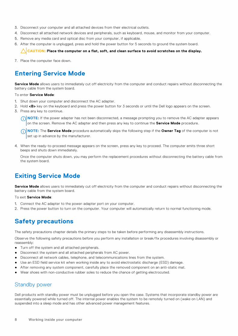
The following image indicates the location of the solid-state drive and provides a visual representation of the installationprocedure.
Steps
1. Align the notch on the solid-state drive with the tab on the solid-state drive slot.
Removing and installing components 33

2. Slide the solid-state drive into the solid-state drive slot on the system board.
3. Replace the (M2x3) screw to secure the solid-state drive to the system board.
Next steps
1. Install the base cover.2. Exit the service mode3. Install the SIM card tray for 4G LTE enabled systems.4. Install the microSD-card.5. Follow the procedure in after working inside your computer.
Removing the M.2 2280 solid-state drive
Prerequisites
1. Follow the procedure in before working inside your computer.2. Remove the microSD-card.3. Remove the SIM card tray for 4G LTE enabled systems.4. Enter the service mode.5. Remove the base cover.
About this task
The following image indicates the location of the solid-state drive and provides a visual representation of the removal procedure.
Steps
1. Remove the (M2x3) screw that secures the solid-state drive to the system board.
2. Slide and remove the solid-state drive from the solid-state drive slot on the system board.
Installing the M.2 2280 solid-state drive
Prerequisites
If you are replacing a component, remove the existing component before performing the installation procedure.
34 Removing and installing components
About this task
The following image indicates the location of the solid-state drive and provides a visual representation of the installationprocedure.
Steps
1. Align the notch on the solid-state drive with the tab on the solid-state drive slot.
2. Slide the solid-state drive into the solid-state drive slot on the system board.
3. Replace the (M2x3) screw to secure the solid-state drive to the system board.
Next steps
1. Install the base cover.2. Exit the service mode3. Install the SIM card tray for 4G LTE enabled systems.4. Install the microSD-card.5. Follow the procedure in after working inside your computer.
Hard-disk drive
Removing the hard-disk drive
Prerequisites
1. Follow the procedure in before working inside your computer.2. Remove the microSD-card.3. Remove the SIM card tray for 4G LTE enabled systems.4. Enter the service mode.5. Remove the base cover.
About this task
The following image indicates the location of the hard-disk drive and provides a visual representation of the removal procedure.
Removing and installing components 35

Steps
1. Lift and disconnect the hard-disk drive cable from the connector on the system board.
2. Loosen the four captive screws that secure the hard-disk drive module to the palmrest assembly.
3. Lift and remove the hard-disk drive module from the slot on the palmrest assembly.
Removing the hard-disk drive bracket
Prerequisites
1. Follow the procedure in before working inside your computer.2. Remove the microSD-card.3. Remove the SIM card tray for 4G LTE enabled systems.4. Enter the service mode.5. Remove the base cover.6. Remove the hard-disk drive.
About this task
The following image indicates the location of the hard-disk drive bracket and provides a visual representation of the removalprocedure.
36 Removing and installing components

Steps
1. Disconnect the hard-disk drive cable from the connector on the hard-disk drive bracket.
2. Remove the four (M3x3) screws that secure the hard-disk drive to the hard-disk drive bracket.
3. Flip the hard-disk drive bracket, lift the silver foil, and remove the hard-disk drive from the hard-disk drive bracket.
Installing the hard-disk drive bracket
Prerequisites
If you are replacing a component, remove the existing component before performing the installation procedure.
About this task
The following image indicates the location of the hard-disk drive bracket and provides a visual representation of the installationprocedure.
Removing and installing components 37

Steps
1. Lift the silver foil, align and place the hard-disk drive in the hard-disk drive bracket.
2. Install the four (M3x3) screws to secure the hard-disk drive to the hard-disk drive bracket.
3. Connect the hard-disk drive cable to the connector on the hard-disk drive bracket.
Next steps
1. Install the hard-disk drive.2. Install the base cover.3. Exit the service mode4. Install the SIM card tray for 4G LTE enabled systems.5. Install the microSD-card.6. Follow the procedure in after working inside your computer.
Installing the hard-disk drive
Prerequisites
If you are replacing a component, remove the existing component before performing the installation procedure.
38 Removing and installing components

About this task
The following image indicates the location of the hard-disk drive and provides a visual representation of the installationprocedure.
NOTE: Systems that are shipped with 3-cell battery contain a rubber bumper that must be removed manually before
installing the hard-disk drive.
Steps
1. Align and place the hard-disk drive module in the slot on the palmrest assembly.
2. Tighten the four captive screws to secure the hard-disk drive module to the palmrest assembly.
3. Connect the hard-disk drive cable to the connector on the system board.
Next steps
1. Install the base cover.2. Exit the service mode3. Install the SIM card tray for 4G LTE enabled systems.4. Install the microSD-card.5. Follow the procedure in after working inside your computer.
WLAN card
Removing the WLAN card
Prerequisites
1. Follow the procedure in before working inside your computer.2. Remove the microSD-card.3. Remove the SIM card tray for 4G LTE enabled systems.4. Enter the service mode.5. Remove the base cover.
Removing and installing components 39

About this task
The following image indicates the location of the WLAN card and provides a visual representation of the removal procedure.
Steps
1. Remove the screw (M2x3) that secures WLAN card bracket to the WLAN card on the system board.
2. Lift and remove the WLAN card bracket from the WLAN card that secures the two antenna cables.
3. Disconnect the antenna cables from the connectors on the WLAN card.
4. Disconnect and remove the WLAN card from the WLAN card slot.
Installing the WLAN card
Prerequisites
If you are replacing a component, remove the existing component before performing the installation procedure.
About this task
The following image indicates the location of the WLAN card and provides a visual representation of the installation procedure.
40 Removing and installing components

Steps
1. Connect the two antenna cables to the connectors on the WLAN card.
NOTE: The antenna cable connectors are fragile and utmost care should be taken while replacing them.
Table 2. Antenna cable guide
Cable color Connector
White cable (Main) White triangle (△) on the WLAN module of the systemboard
Black cable (Aux) Solid triangle (▲) on the WLAN module of the system board
2. Align the notch on the WLAN card with the tab on the WLAN card slot.
3. Slide the WLAN card at an angle into the WLAN card slot.
4. Align and place the WLAN card bracket on the WLAN card.
5. Install the screw (M2x3) to secure the WLAN card bracket on the WLAN card to the system board.
Next steps
1. Install the base cover.
Removing and installing components 41

2. Exit the service mode3. Install the SIM card tray for 4G LTE enabled systems.4. Install the microSD-card.5. Follow the procedure in after working inside your computer.
WWAN card
Removing the WWAN card
Prerequisites
1. Follow the procedure in before working inside your computer.2. Remove the microSD-card.3. Remove the SIM card tray for 4G LTE enabled systems.4. Enter the service mode.5. Remove the base cover.
About this task
The following image indicates the location of the WWAN card and provides a visual representation of the removal procedure.
NOTE: The following steps are applicable only for 4G LTE enabled systems.
42 Removing and installing components

Steps
1. Remove the screw (M2x3) that secures WWAN card bracket to the WWAN card on the system board.
2. Lift and remove the WWAN card bracket from the WWAN card that secures the two antenna cables.
3. Disconnect the antenna cables from the connectors on the WWAN card.
4. Disconnect and remove the WWAN card from the WWAN card slot.
Installing the WWAN card
Prerequisites
If you are replacing a component, remove the existing component before performing the installation procedure.
About this task
The following image indicates the location of the WWAN card and provides a visual representation of the installation procedure.
NOTE: The following steps are applicable only for 4G LTE enabled systems.
Steps
1. Connect the two antenna cables to the connectors on the WWAN card.
NOTE: The antenna cable connectors are fragile and utmost care should be taken while replacing them.
Table 3. Antenna cable guide
Removing and installing components 43

Table 3. Antenna cable guide
Cable color Connector
White cable (Main) White triangle (△) on the WLAN module of the systemboard
Black cable (Aux) Solid triangle (▲) on the WLAN module of the system board
2. Align the notch on the WWAN card with the tab on the WWAN card slot.
3. Slide the WWAN card at an angle into the WWAN card slot.
4. Align and place the WLAN card bracket on the WLAN card.
5. Install the screw (M2x3) to secure the WLAN card bracket on the WLAN card to the system board.
Next steps
1. Install the base cover.2. Exit the service mode3. Install the SIM card tray for 4G LTE enabled systems.4. Install the microSD-card.5. Follow the procedure in after working inside your computer.
I/O cable
Removing the I/O cable
Prerequisites
1. Follow the procedure in before working inside your computer.2. Remove the SIM card tray for 4G LTE enabled systems.3. Enter the service mode.4. Remove the base cover.
About this task
The following image indicates the location of the I/O cable and provides a visual representation of the removal procedure.
44 Removing and installing components

Steps
1. Peel the adhesive tape, open the latch and disconnect the I/O cable from the connector on the system board.
2. Peel the adhesive tape and unroute the I/O cable from the routing guides in the palmrest assembly.
3. Peel the adhesive tape, open the latch and disconnect the I/O cable from the connector on the I/O board.
4. Lift and remove the I/O cable from the palmrest assembly.
Installing the I/O cable
Prerequisites
If you are replacing a component, remove the existing component before performing the installation procedure.
About this task
The following image indicates the location of the I/O cable and provides a visual representation of the installation procedure.
Removing and installing components 45

Steps
1. Route the I/O cable through the routing guides and adhere the adhesive tape to secure the I/O cable in place.
2. Adhere the adhesive tape, connect the I/O cable to the connector on the system board, and close the latch.
3. Adhere the adhesive tape, connect the I/O cable to the connector on the I/O board, and close the latch.
Next steps
1. Install the base cover.2. Exit the service mode3. Install the microSD-card.4. Install the SIM card tray for 4G LTE enabled systems.5. Follow the procedure in after working inside your computer.
Display assembly
Removing the display assembly
Prerequisites
1. Follow the procedure in before working inside your computer.2. Remove the microSD-card.3. Remove the SIM card tray for 4G LTE enabled systems.4. Enter the service mode.5. Remove the base cover.6. Remove the WLAN card.7. Remove the WWAN card for systems enabled with 4G LTE.8. Remove the I/O cable.
46 Removing and installing components

About this task
The following images indicate the location of the display assembly and provide a visual representation of the removal procedure.
Removing and installing components 47

Steps
1. Unroute the display cable from the routing guides in the palmrest assembly.
2. Peel the adhesive tape that secures the display cable in place.
3. Open the latch and disconnect the display cable from the connector on the system board.
4. Remove the (M2.5x4) and six (M2.5x6) screws that secure the display hinges to the system.
5. Lift the left and right hinges in upward direction away from the palmrest assembly.
6. Lift the display assembly off the palmrest assembly.
48 Removing and installing components

Installing the display assembly
Prerequisites
If you are replacing a component, remove the existing component before performing the installation procedure.
About this task
The following images indicate the location of the display assembly and provide a visual representation of the installationprocedure.
Removing and installing components 49

Steps
1. Align and place the system chassis under the hinges of the display assembly.
2. Press the left and right hinges in downward direction toward the palmrest assembly.
3. Install the (M2.5x4) and six (M2.5x6) screws to secure the display hinges to the palmrest assembly.
4. Connect the display cable to the connector on the system board and close the latch.
5. Route the display cable through the routing guides in the palmrest assembly.
6. Affix the adhesive tape to secures the display cable in place.
Next steps
1. Install the I/O cable.2. Install the WWAN card for systems enabled with 4G LTE.3. Install the WLAN card.4. Install the base cover.5. Exit the service mode6. Install the SIM card tray for 4G LTE enabled systems.7. Install the microSD-card.8. Follow the procedure in after working inside your computer.
50 Removing and installing components

System fan
Removing the system fan
Prerequisites
1. Follow the procedure in before working inside your computer.2. Remove the microSD-card.3. Remove the SIM card tray for systems enabled with 4G LTE.4. Enter the service mode.5. Remove the base cover.
About this task
The following image indicates the location of the system fan and provides a visual representation of the removal procedure.
Steps
1. Disconnect the system fan cable from the connector on the system board.
2. Remove the two (M2x3) screws that secure the system fan to the palmrest assembly.
3. Lift and remove the system fan from the palmrest assembly.
Installing the system fan
Prerequisites
If you are replacing a component, remove the existing component before performing the installation procedure.
Removing and installing components 51

About this task
The following image indicates the location of the system fan and provides a visual representation of the installation procedure.
Steps
1. Align and place the system fan into the slot on the palmrest assembly.
2. Install the two (M2x3) screws to secure the system fan to the palmrest assembly.
3. Connect the system fan cable to the connector on the system board.
Next steps
1. Install the base cover.2. Exit the service mode3. Install the SIM card tray for systems enabled with 4G LTE.4. Install the microSD-card.5. Follow the procedure in after working inside your computer.
Heatsink assembly
Removing the heatsink assembly
Prerequisites
1. Follow the procedure in before working inside your computer.2. Remove the microSD-card.3. Remove the SIM card tray for systems enabled with 4G LTE.4. Enter the service mode.5. Remove the base cover.
52 Removing and installing components

About this task
The following images indicate the location of the heatsink assembly and provide a visual representation of the removalprocedure.
NOTE: The following images are from systems shipped with discrete graphic card. The system board has a different
configuration for integrated graphic cards.
Steps
1. For systems enabled with integrated graphic card, loosen the four captive screws (in reverse order, 4->3->2->1) that securethe heatsink assembly to the system board.
2. For systems enabled with discrete graphic card, loosen the seven captive screws (in reverse order, 7>6>5>4->3->2->1) thatsecure the heatsink assembly to the system board.
3. Lift and remove the heatsink assembly from the system board.
Installing the heatsink assembly
Prerequisites
If you are replacing a component, remove the existing component before performing the installation procedure.
About this task
The following image indicates the location of the heatsink assembly and provides a visual representation of the installationprocedure.
NOTE: The following images are from systems shipped with discrete graphic card. The system board has a different
configuration for integrated graphic cards.
Removing and installing components 53

Steps
1. Align and place the heatsink assembly into the slot on the system board.
2. For systems enabled with integrated graphic card, tighten the four captive screws to secure the heatsink assembly to thesystem board.
3. For systems enabled with discrete graphic card, tighten the seven captive screws to secure the heatsink assembly to thesystem board.
Next steps
1. Install the base cover.2. Exit the service mode3. Install the SIM card tray for systems enabled with 4G LTE.4. Install the microSD-card.5. Follow the procedure in after working inside your computer.
Power adapter port
Removing the power adapter port
Prerequisites
1. Follow the procedure in before working inside your computer.2. Remove the microSD-card.3. Remove the SIM card tray for 4G LTE enabled systems.4. Enter the service mode.5. Remove the base cover.
54 Removing and installing components

About this task
The following image indicates the location of the power adapter port and provides a visual representation of the removalprocedure.
Steps
1. Remove the (M2.5x4) and two (M2.5x6) screws that secure the display hinges to the system.
2. Disconnect the power adapter port from the connector on the system board.
3. Remove the (M2x3) screw that secures the power adapter port to the palmrest assembly.
4. Lift and remove the power adapter port from the palmrest assembly.
Installing the power adapter port
About this task
The following image indicates the location of the power adapter port and provides a visual representation of the removalprocedure.
Removing and installing components 55

Steps
1. Align and place the power adapter port on the palmrest assembly.
2. Install the (M2x3) screw to secure the power adapter port to the palmrest assembly.
3. Connect the power adapter port to the connector on the system board.
4. Install the (M2.5x4) and two (M2.5x6) screws to secure the display hinges to the system.
Next steps
1. Install the base cover.2. Exit the service mode3. Install the SIM card tray for 4G LTE enabled systems.4. Install the microSD-card.5. Follow the procedure in after working inside your computer.
Coin-cell battery
Removing the coin-cell battery
Prerequisites
1. Follow the procedure in before working inside your computer.2. Remove the microSD-card.3. Remove the SIM card tray for 4G LTE enabled systems.4. Enter the service mode.5. Remove the base cover.
About this task
The following image indicates the location of the coin-cell battery and provides a visual representation of the removal procedure.
NOTE: The following image is from computers with discrete graphic card. For computers with integrated graphic card, the
system board has a different configuration.
56 Removing and installing components

Steps
1. Disconnect the coin-cell battery cable from the connector on the I/O board.
2. Lift and remove the coin-cell battery from the palmrest assembly.
Installing the coin-cell battery
Prerequisites
If you are replacing a component, remove the existing component before performing the installation procedure.
About this task
The following image indicates the location of the coin-cell battery and provides a visual representation of the installationprocedure.
NOTE: The following image is from computers with discrete graphic card. For computers with integrated graphic card, the
system board has a different configuration.
Removing and installing components 57

Steps
1. Align and place the coin-cell battery on the palmrest assembly.
2. Connect the coin-cell battery cable to the connector on the I/O board.
Next steps
1. Install the base cover.2. Exit the service mode3. Install the SIM card tray for 4G LTE enabled systems.4. Install the microSD-card.5. Follow the procedure in after working inside your computer.
USB cable
Removing the USB cable
Prerequisites
1. Follow the procedure in before working inside your computer.2. Remove the microSD-card.3. Remove the SIM card tray for 4G LTE enabled systems.4. Remove the base cover.5. Remove the battery.6. Remove the hard-disk drive.
About this task
The following image indicates the location of the USB cable and provides a visual representation of the removal procedure.
58 Removing and installing components

Steps
1. Open the latch and disconnect the USB cable from the connector on the system board.
2. Carefully peel the USB cable from the palmrest assembly.
3. Open the latch and disconnect the USB cable from the connector on the I/O board.
4. Lift and remove the USB cable from the palmrest assembly.
Installing the USB cable
Prerequisites
If you are replacing a component, remove the existing component before performing the installation procedure.
About this task
The following image indicates the location of the USB cable and provides a visual representation of the installation procedure.
Removing and installing components 59

Steps
1. Connect the USB cable to the connector on the system board and close the latch.
2. Align and adhere the USB cable on the palmrest assembly.
3. Connect the USB cable to the connector on the I/O board and close the latch.
Next steps
1. Install the hard-disk drive.2. Install the battery.3. Install the base cover.4. Install the SIM card tray for 4G LTE enabled systems.5. Install the microSD-card.6. Follow the procedure in after working inside your computer.
Ethernet port
Removing the ethernet port
Prerequisites
1. Follow the procedure in before working inside your computer.2. Remove the microSD-card.3. Remove the SIM card tray for 4G LTE enabled systems.4. Enter the service mode.5. Remove the base cover.
About this task
The following image indicates the location of the ethernet port and provides a visual representation of the removal procedure.
Steps
1. Remove the four (M2.5x6) screws to secure the hinge bracket on the palmrest assembly.
2. Lift the hinge in upward direction away from the palmrest assembly.
60 Removing and installing components

3. Remove the two (M2x5) screws that secure the ethernet on the I/O board.
4. Lift and remove the ethernet from the I/O board.
Installing the ethernet port
Prerequisites
If you are replacing a component, remove the existing component before performing the installation procedure.
About this task
The following image indicates the location of the ethernet port and provides a visual representation of the installation procedure.
Steps
1. Align and place the ethernet on the I/O board.
2. Install the two (M2x5) screws to secure the ethernet on the I/O board.
3. Press the hinge in downward direction toward the palmrest assembly.
4. Install the four (M2.5x6) screws to secure the hinge bracket on the palmrest assembly.
Next steps
1. Install the base cover.2. Exit the service mode3. Install the SIM card tray for 4G LTE enabled systems.4. Install the microSD-card.5. Follow the procedure in after working inside your computer.
Removing and installing components 61

I/O board
Removing the I/O board
Prerequisites
1. Follow the procedure in before working inside your computer.2. Remove the microSD-card.3. Remove the SIM card tray for 4G LTE enabled systems.4. Enter the service mode.5. Remove the base cover.6. Remove the ethernet port.
About this task
NOTE: The following image is from computers with discrete graphic card. For computers with integrated graphic card, the
system board has a different configuration.
The following image indicates the location of the I/O board and provides a visual representation of the removal procedure.
Steps
1. For systems shipped with power-button board, peel the adhesive, open the latch and disconnect the power-button boardcable from the connector on the I/O board.
2. Open the latch and disconnect the I/O cable from the connector on the system board.
3. Disconnect the USB cable and coin-cell cable from the connectors on the system board.
4. Remove the two (M2x3) screws that secure the I/O board on the palmrest assembly.
5. Lift and remove the I/O board from the palmrest assembly.
62 Removing and installing components

Installing the I/O board
Prerequisites
If you are replacing a component, remove the existing component before performing the installation procedure.
About this task
NOTE: The following image is from computers with discrete graphic card. For computers with integrated graphic card, the
system board has a different configuration.
The following image indicates the location of the I/O board and provides a visual representation of the installation procedure.
Steps
1. Align and place the I/O board into its slot on the palmrest assembly.
2. Install the two (M2x3) screws that secure the I/O board on the palmrest assembly.
3. Connect the USB cable and coin-cell cable to the connectors on the system board.
4. Connect the I/O cable to the connector on the system board and close the latch.
5. For systems shipped with power-button board, connect the power-button board cable to the connector on the I/O board,close the latch and affix the adhesive tape.
Next steps
1. Install the ethernet port.2. Install the base cover.3. Exit the service mode4. Install the SIM card tray for 4G LTE enabled systems.5. Install the microSD-card.6. Follow the procedure in after working inside your computer.
Removing and installing components 63

Power-button board
Removing the power-button board
Prerequisites
1. Follow the procedure in before working inside your computer.2. Remove the microSD-card.3. Remove the SIM card tray for 4G LTE enabled systems.4. Enter the service mode.5. Remove the base cover.6. Remove the I/O board.7. Remove the ethernet port.
About this task
The following image indicates the location of the power-button board and provides a visual representation of the removalprocedure.
NOTE: The following images are from systems shipped with discrete graphic card. The system board has a different
configuration for integrated graphic cards.
Steps
1. Peel the power-button cable with adhesive backing from the palmrest assembly.
2. Lift the power-button board off the palmrest assembly.
Installing the power-button board
About this task
The following image indicates the location of the power-button board and provides a visual representation of the removalprocedure.
NOTE: The following images are from systems shipped with discrete graphic card. The system board has a different
configuration for integrated graphic cards.
64 Removing and installing components

Steps
1. Affix the power-button cable with adhesive backing.
2. Align and place the power-button board into the slot on the palmrest assembly.
Next steps
1. Install the ethernet port.2. Install the I/O board.3. Install the base cover.4. Exit the service mode5. Install the SIM card tray for 4G LTE enabled systems.6. Install the microSD-card.7. Follow the procedure in after working inside your computer.
System board
Removing the system board
Prerequisites
1. Follow the procedure in before working inside your computer.2. Remove the microSD-card.3. Remove the SIM card tray for 4G LTE enabled systems.4. Remove the base cover.5. Remove the battery.6. Remove the memory module.7. Remove the M.2 SSD.8. Remove the hard-disk drive for systems shipped with hard-disk drive.9. Remove the WLAN card.10. Remove the heatsink assembly.
Removing and installing components 65

About this task
Figure 1. System board connectors
1. System fan cable 2. Display cable
3. Power adapter cable 4. Memory module connector
5. Keyboard backlit LED cable 6. Keyboard cable
7. Touchpad cable 8. Battery cable
9. WLAN card connector 10. Hard-disk drive cable
11. USB cable 12. Speaker cable
13. I/O cable 14. M.2 SSD connector
The following images indicate the location of the system board and provide a visual representation of the removal procedure.
66 Removing and installing components

Removing and installing components 67

Steps
1. Remove the two (M2.5x6) and the (M2.5x4) screws that secure the hinge to the palmrest assembly.
2. Lift the hinge in upward direction away from the palmrest assembly.
3. For 4G LTE enabled systems, peel the WWAN I/O board cable from the palmrest assembly.
4. Disconnect the speaker cable, power adapter port cable, hard-disk drive cable, and system fan cable from the connector onthe system board.
5. Open the latch and disconnect the touchpad cable, keyboard cable, and USB cable from the connector on the system board.
6. Peel the adhesive, open the latch, and disconnect the display cable and I/O cable from the connector on the system board.
7. Remove the two (M2x5) screws that secure the type-c bracket in place.
8. Lift and remove the type-c bracket from the system board.
9. Remove the two (M2x2) screws that secure the system board in place.
10. Lift and remove the system board from the palmrest assembly.
Installing the system board
Prerequisites
If you are replacing a component, remove the existing component before performing the installation procedure.
68 Removing and installing components

About this task
Figure 2. System board connectors
1. System fan cable 2. Display cable
3. Power adapter cable 4. Memory module connector
5. Keyboard backlit LED cable 6. Keyboard cable
7. Touchpad cable 8. Battery cable
9. WLAN card connector 10. Hard-disk drive cable
11. USB cable 12. Speaker cable
13. I/O cable 14. M.2 SSD connector
The following images indicate the location of the system board and provide a visual representation of the installation procedure.
Removing and installing components 69

70 Removing and installing components

Steps
1. Align and place the system board into the slot on the palmrest assembly.
2. Install the two (M2x2) screws to secure the system board in place.
3. Align and place the type-c bracket on the system board.
4. Install the two (M2x5) screws to secure the type-c bracket in place.
5. Connect the display cable and I/O cable to the connector on the system board, close the latches and affix the adhesivetapes.
6. Connect the touchpad cable, keyboard cable, and USB cable to the connector on the system board and close the latches.
7. Connect the speaker cable, power adapter port cable, hard-disk drive cable, and system fan cable to the connector on thesystem board.
8. For 4G LTE enabled systems, affix the WWAN I/O board cable on the palmrest assembly.
9. Press the hinge in downward direction toward the palmrest assembly.
10. Install the two (M2.5x6) and the (M2.5x4) screws to secure the hinge to the palmrest assembly.
Next steps
1. Install the heatsink assembly.2. Install the WLAN card.3. Install the hard-disk drive for systems shipped with hard-disk drive.4. Install the M.2 SSD.5. Install the memory module.6. Install the battery.7. Install the base cover.8. Install the SIM card tray for 4G LTE enabled systems.9. Install the microSD-card.10. Follow the procedure in after working inside your computer.
Removing and installing components 71

Speakers
Removing the speaker
Prerequisites
1. Follow the procedure in before working inside your computer.2. Remove the microSD-card.3. Remove the SIM card tray for 4G LTE enabled systems.4. Remove the base cover.5. Remove the battery.
About this task
The following image indicates the location of the speakers and provides a visual representation of the removal procedure.
Steps
1. Disconnect the speaker cable from the connector on the system board.
2. Unroute the speaker cable from the routing guides in the palmrest assembly.
3. Peel the adhesive tapes, lift and remove the speakers off the palmrest assembly.
Installing the speaker
Prerequisites
If you are replacing a component, remove the existing component before performing the installation procedure.
About this task
The following image indicates the location of the speakers and provides a visual representation of the installation procedure.
72 Removing and installing components

Steps
1. Align and place the speakers into the slot on the palmrest assembly.
2. Route the speaker cable through the routing guides in the palmrest assembly.
3. Connect the speaker cable to the connector on the system board.
4. Affix the adhesive tapes to secure the speakers in place.
Next steps
1. Install the battery.2. Install the base cover.3. Install the SIM card tray for 4G LTE enabled systems.4. Install the microSD-card.5. Follow the procedure in after working inside your computer.
Touchpad
Removing the touchpad
Prerequisites
1. Follow the procedure in before working inside your computer.2. Remove the microSD-card.3. Remove the SIM card tray for 4G LTE enabled systems.4. Remove the base cover.5. Remove the battery.6. Remove the speakers.
About this task
The following image indicates the location of the touchpad and provides a visual representation of the removal procedure.
Removing and installing components 73

Steps
1. Open the latch and disconnect the touchpad cable from the connector on the system board.
2. Peel the adhesive tapes that secure the touchpad module in place.
3. Remove the three (M2.5x2) screws that secure the touchpad bracket to the touchpad module.
4. Lift and remove the touchpad bracket from the touchpad module.
5. Remove the four (M2x2) screws that secure the touchpad module to the palmrest assembly.
6. Lift and remove the touchpad module from the palmrest assembly.
Installing the touchpad
Prerequisites
If you are replacing a component, remove the existing component before performing the installation procedure.
About this task
The following image indicates the location of the touchpad and provides a visual representation of the installation procedure.
74 Removing and installing components

Steps
1. Align and place the touchpad module into the slot on the palmrest assembly.
2. Install the four (M2x2) screws to secure the touchpad module to the palmrest assembly.
3. Align and place the touchpad bracket on the touchpad module.
4. Install the three (M2.5x2) screws to secure the touchpad bracket to the touchpad module.
5. Affix the adhesive tapes to secure the touchpad module in place.
6. Connect the touchpad cable to the connector on the system board and close the latch.
Next steps
1. Install the speakers.2. Install the battery.3. Install the base cover.4. Install the SIM card tray for 4G LTE enabled systems.5. Install the microSD-card.6. Follow the procedure in after working inside your computer.
WWAN I/O board
Removing the WWAN I/O board
Prerequisites
1. Follow the procedure in before working inside your computer.2. Remove the microSD card.3. Remove the SIM card tray for 4G LTE enabled systems.4. Remove the base cover.5. Remove the battery cable.
Removing and installing components 75

About this task
The following image indicates the location of the WWAN I/O board and provides a visual representation of the removalprocedure.
NOTE: The following steps are applicable only for 4G LTE enabled systems.
Steps
1. Remove the two (M2x3) screws that secure the WWAN I/O board to the palmrest assembly.
2. Open the latch and disconnect the WWAN cable from the connector on the WWAN I/O board.
3. Lift and remove the WWAN I/O board from the palmrest assembly.
Installing the WWAN I/O board
Prerequisites
If you are replacing a component, remove the existing component before performing the installation procedure.
About this task
The following image indicates the location of the WWAN I/O board and provides a visual representation of the installationprocedure.
NOTE: The following steps are applicable only for 4G LTE enabled systems.
76 Removing and installing components

Steps
1. Connect the WWAN cable to the connector on the WWAN I/O board and close the latch.
2. Align and place the WWAN I/O board into its slot on the palmrest assembly.
3. Install the two (M2x3) screws to secure the WWAN I/O board to the palmrest assembly.
Next steps
1. Install the battery cable2. Install the base cover.3. Install the SIM card tray for 4G LTE enabled systems.4. Install the microSD card.5. Follow the procedure in After working on your computer.
Palmrest assembly
Removing the palmrest assembly
Prerequisites
1. Follow the procedure in before working inside your computer.2. Remove the microSD-card.3. Remove the SIM card tray for 4G LTE enabled systems.4. Remove the base cover.5. Remove the battery.6. Remove the memory module.7. Remove the M.2 SSD.8. Remove the M.2 SSD thermal plate.9. Remove the M.2 SSD conversion bracket.10. Remove the hard-disk drive.11. Remove the WLAN card.12. Remove the WWAN card for systems enabled with 4G LTE.13. Remove the I/O board cable.
Removing and installing components 77

14. Remove the display assembly.15. Remove the system fan.16. Remove the heatsink assembly.17. Remove the power adapter port.18. Remove the I/O board.19. Remove the coin-cell battery.20. Remove the USB cable.21. Remove the WWAN I/O board for systems enabled with 4G LTE.22. Remove the system board.
NOTE: The system board can be removed along with the heat sink.
About this task
The following images indicate the location of the palmrest assembly.
Steps
After performing the preceding steps, you are left with the palmrest assembly.
Installing the palmrest assembly
Prerequisites
If you are replacing a component, remove the existing component before performing the installation procedure.
About this task
The following image indicates the palmrest assembly.
78 Removing and installing components

Steps
After performing the succeeding steps, you are left with the palmrest assembly.
Next steps
1. Install the system board.2. Install the WWAN I/O board for systems enabled with 4G LTE.3. Install the USB cable.4. Install the coin-cell battery.5. Install the I/O board.6. Install the power adapter port.7. Install the heatsink assembly.8. Install the system fan.9. Install the display assembly.10. Install the I/O board cable.11. Install the WWAN card for systems enabled with 4G LTE.12. Install the WLAN card.13. Install the hard-disk drive.14. Install the M.2 SSD conversion bracket.15. Install the M.2 SSD thermal plate.16. Install the M.2 SSD.17. Install the memory module.18. Install the battery.19. Install the base cover.20. Install the SIM card tray for 4G LTE enabled systems.21. Install the microSD-card.22. Follow the procedure in after working inside your computer.
Removing and installing components 79

Display bezel
Removing the display bezel
Prerequisites
1. Follow the procedure in before working inside your computer.2. Remove the microSD-card.3. Remove the SIM card tray for 4G LTE enabled systems.4. Enter the service mode.5. Remove the base cover.6. Remove the WLAN card.7. Remove the WWAN card for 4G LTE enabled systems.8. Remove the I/O board cable.9. Remove the display assembly.
About this task
The following images indicate the location of the display bezel and provide a visual representation of the removal procedure.
Steps
1. Use a plastic scribe to carefully pry open the top, left, and right sides of the display bezel.
CAUTION: When prying open the display bezel, ensure to pry along the outside edge of the display bezel
using your hand or a plastic scribe. Using a screw driver or any sharp object may damage the display cover.
2. Lift and remove the display bezel from the display assembly.
80 Removing and installing components

Installing the display bezel
Prerequisites
If you are replacing a component, remove the existing component before performing the installation procedure.
About this task
The following image indicates the location of the display bezel and provides a visual representation of the installation procedure.
Steps
Align the display bezel with the display assembly. Gently snap the display bezel into place.
Next steps
1. Install the display assembly.2. Install the I/O board cable.3. Install the WWAN card for 4G LTE enabled systems.4. Install the WLAN card.5. Install the base cover.6. Exit the service mode7. Install the SIM card tray for 4G LTE enabled systems.8. Install the microSD-card.9. Follow the procedure in after working inside your computer.
Removing and installing components 81

Display panel
Removing the display panel
Prerequisites
1. Follow the procedure in before working inside your computer.2. Remove the microSD-card.3. Remove the SIM card tray for 4G LTE enabled systems.4. Enter the service mode.5. Remove the base cover.6. Remove the WLAN card.7. Remove the WWAN card for 4G LTE enabled systems.8. Remove the I/O board cable.9. Remove the display assembly.10. Remove the display bezel.
About this task
NOTE: The display panel is pre-assembled with the display brackets as a single service part. Do not pull and release the
Stretch Release (SR) Tapes from the display panel and separate the brackets from the display panel.
The following images indicate the location of the display panel and provide a visual representation of the removal procedure.
82 Removing and installing components

Removing and installing components 83

84 Removing and installing components

Steps
1. Remove the six (M2.5x2.5) and two (M2.5x3) screws that secure the left and right hinge brackets in place.
2. Gently flip over the display panel.
3. Peel the adhesive tape, open the latch and disconnect the display cable from the connector on the display panel.
4. Lift and remove the display panel from the display assembly.
Installing the display panel
Prerequisites
If you are replacing a component, remove the existing component before performing the installation procedure.
About this task
NOTE: The display panel is pre-assembled with the display brackets as a single service part. Do not pull and release the
Stretch Release (SR) Tapes from the display panel and separate the brackets from the display panel.
The following images indicate the location of the display panel and provide a visual representation of the installation procedure.
Removing and installing components 85

86 Removing and installing components

Steps
1. Align and place the display panel on the display assembly.
2. Connect the display cable to the connector on the display panel, close the latch and affix the adhesive tape.
3. Install the six (M2.5x2.5) and two (M2.5x3) screws to secure the left and right hinge brackets in place.
4. Gently flip over the display panel.
Next steps
1. Install the display bezel.2. Install the display assembly.3. Install the I/O board cable.4. Install the WWAN card for 4G LTE enabled systems..5. Install the WLAN card.6. Install the base cover.7. Exit the service mode8. Install the SIM card tray for 4G LTE enabled systems.9. Install the microSD-card.10. Follow the procedure in after working inside your computer.
Removing and installing components 87

Camera
Removing the camera
Prerequisites
1. Follow the procedure in before working inside your computer.2. Remove the microSD-card.3. Remove the SIM card tray for 4G LTE enabled systems.4. Enter the service mode.5. Remove the base cover.6. Remove the WLAN card.7. Remove the WWAN card for 4G LTE enabled systems.8. Remove the I/O board cable.9. Remove the display assembly.10. Remove the display bezel.11. Remove the display panel.
About this task
The following image indicates the location of the camera and provides a visual representation of the removal procedure.
Steps
1. Peel the adhesive that secures the camera cable to the connector on the camera module.
2. Disconnect the camera cable from the connector on the camera module.
3. Peel the camera cable from the display back-cover.
4. Carefully pry loose and remove the camera module from the display back-cover.
Installing the camera
Prerequisites
If you are replacing a component, remove the existing component before performing the installation procedure.
88 Removing and installing components

About this task
The following image indicates the location of the camera and provides a visual representation of the installation procedure.
Steps
1. Align and place the camera module into the slot on the display back-cover.
2. Connect the camera cable to the connector on the camera module.
3. Affix the adhesive tape to secure the camera cable to the connector on the camera module.
4. Align and affix the camera cable on the display back-cover.
Next steps
1. Install the display panel.2. Install the display bezel.3. Install the display assembly.4. Install the I/O board cable.5. Install the WWAN card for 4G LTE enabled systems.6. Install the WLAN card.7. Install the base cover.8. Exit the service mode9. Install the SIM card tray for 4G LTE enabled systems.10. Install the microSD-card.11. Follow the procedure in after working inside your computer.
Display cable
Removing the display cable
Prerequisites
1. Follow the procedure in before working inside your computer.2. Remove the microSD-card.3. Remove the SIM card tray for 4G LTE enabled systems.4. Enter the service mode.5. Remove the base cover.6. Remove the WLAN card.7. Remove the WWAN card for 4G LTE enabled systems.
Removing and installing components 89

8. Remove the I/O board cable.9. Remove the display assembly.10. Remove the display bezel.11. Remove the display panel.
About this task
The following image indicates the location of the display cable and provides a visual representation of the removal procedure.
Steps
1. Disconnect the display cable from the connector on the system board.
2. Disconnect the display cable from the connector on the display panel.
3. Disconnect the display cable from the connector on the camera module.
Installing the display cable
Prerequisites
If you are replacing a component, remove the existing component before performing the installation procedure.
90 Removing and installing components

About this task
The following image indicates the location of the display cable and provides a visual representation of the installation procedure.
Steps
1. Connect the display cable from the connector on the camera module.
2. Connect the display cable from the connector on the display panel.
3. Connect the display cable from the connector on the system board.
Next steps
1. Install the display panel.2. Install the display bezel.3. Install the display assembly.4. Install the I/O board cable.5. Install the WWAN card for 4G LTE enabled systems. .6. Install the WLAN card.7. Install the base cover.8. Exit the service mode9. Install the SIM card tray for 4G LTE enabled systems.10. Install the microSD-card.11. Follow the procedure in after working inside your computer.
Removing and installing components 91

Display back-cover
Removing the display back-cover
Prerequisites
1. Follow the procedure in before working inside your computer.2. Remove the microSD-card.3. Remove the SIM card tray for 4G LTE enabled systems.4. Enter the service mode.5. Remove the base cover.6. Remove the WLAN card.7. Remove the WWAN card for 4G LTE enabled systems.8. Remove the I/O board cable.9. Remove the display assembly.10. Remove the display bezel.11. Remove the display panel.12. Remove the camera.13. Remove the display cable.
About this task
The following images indicate the location of the display back-cover and provide a visual representation of the removalprocedure.
Steps
After performing the preceding steps, you are left with the base cover assembly.
Installing the display back-cover
Prerequisites
If you are replacing a component, remove the existing component before performing the installation procedure.
92 Removing and installing components

About this task
The following image indicates the location of the display back-cover and provides a visual representation of the installationprocedure.
Steps
After performing the succeeding steps, you are left with the base cover assembly.
Next steps
1. Install the display cable.2. Install the camera.3. Install the display panel.4. Install the display bezel.5. Install the display assembly.6. Install the I/O board cable.7. Install the WWAN card for 4G LTE enabled systems. .8. Install the WLAN card.9. Install the base cover.10. Exit the service mode11. Install the SIM card tray for 4G LTE enabled systems.12. Install the microSD-card.13. Follow the procedure in after working inside your computer.
Removing and installing components 93

Drivers and downloadsWhen troubleshooting, downloading, or installing drivers, it is recommended that you read the Dell knowledge base article,Drivers and Downloads FAQs .
3
94 Drivers and downloads

System setupCAUTION: Unless you are an expert computer user, do not change the settings in the BIOS Setup program.
Certain changes can make your computer work incorrectly.
NOTE: Before you change BIOS Setup program, it is recommended that you write down the BIOS Setup program screen
information for future reference.
Use the BIOS Setup program for the following purposes:● Get information about the hardware installed in your computer, such as the amount of RAM and the size of the hard drive.● Change the system configuration information.● Set or change a user-selectable option, such as the user password, type of hard drive installed, and enabling or disabling
base devices.
Topics:
• Boot menu• Boot Sequence• Navigation keys• System setup options• Updating the BIOS in Windows• System and setup password
Boot menuTo initiate a one-time boot menu with a list of the valid boot devices for the system, press <F12> when the Dell logo is displayed.Diagnostics and BIOS Setup options are also in this menu. The devices that are listed on the boot menu depend on the bootabledevices in the system. This menu is useful when you are attempting to boot to a particular device or to bring up the diagnosticsfor the system. Using the boot menu, do not change the boot order that is stored in the BIOS.
The options are:● Legacy External Device Boot
○ Onboard NIC● UEFI Boot:
○ UEFI: TOSHIBA MQ01ACF050● Other Options:
○ BIOS Setup○ Device Configuration○ BIOS Flash Update○ Diagnostics○ Intel (R) Management Engine BIOS Extension (MEBx)○ Change Boot Mode Settings
Boot SequenceBoot sequence enables you to bypass the System Setup–defined boot device order and boot directly to a specific device (forexample: optical drive or hard drive). During the Power-on Self-Test (POST), when the Dell logo appears, you can:● Access System Setup by pressing F2 key● Bring up the one-time boot menu by pressing F12 key.
The one-time boot menu displays the devices that you can boot from including the diagnostic option. The boot menu optionsare:
4
System setup 95

● Removable Drive (if available)● STXXXX Drive
NOTE: XXXX denotes the SATA drive number.
● Optical Drive (if available)● SATA Hard Drive (if available)● Diagnostics
NOTE: Choosing Diagnostics, displays the SupportAssist screen.
The boot sequence screen also displays the option to access the System Setup screen.
Navigation keysNOTE: For most of the System Setup options, changes that you make are recorded but do not take effect until you restart
the system.
Keys Navigation
Up arrow Moves to the previous field.
Down arrow Moves to the next field.
Enter Selects a value in the selected field (if applicable) or follow the link in the field.
Spacebar Expands or collapses a drop-down list, if applicable.
Tab Moves to the next focus area.
Esc Moves to the previous page until you view the main screen. Pressing Esc in the main screen displays amessage that prompts you to save any unsaved changes and restarts the system.
System setup options
NOTE: Depending on your system and its installed devices, the items that are listed in this section may or may not appear.
Table 4. System setup options—System information menu
Overview
Latitude 3520
BIOS Version Displays the BIOS version number.
Service Tag Displays the Service Tag of the system.
Asset Tag Displays the Asset Tag of the system.
Manufacture Date Displays the manufacture date of the system.
Ownership Date Displays the ownership date of the system.
Express Service Code Displays the express service code of the system.
Ownership Tag Displays the Ownership Tag of the system.
Signed Firmware Update Displays whether the Signed Firmware Update is enabled on your system.
Battery Information
Primary Displays that battery is primary.
Battery Level Displays the battery level of the system.
Battery State Displays the battery state of the system.
Health Displays the battery health of the system.
AC Adapter Displays whether the AC adapter is connected or not.
96 System setup

Table 4. System setup options—System information menu
Overview
Processor Information
Processor Type Displays the processor type.
Maximum Clock Speed Displays the maximum processor clock speed.
Minimum Clock Speed Displays the minimum processor clock speed.
Current Clock Speed Displays the current processor clock speed.
Core Count Displays the number of cores on the processor.
Processor ID Displays the processor identification code.
Processor L2 Cache Displays the processor L2 Cache size.
Processor L3 Cache Displays the processor L3 Cache size.
Microcode Version Displays the microcode version.
Intel Hyper-Threading Capable Displays whether the processor is Hyper-Threading (HT) capable.
64-Bit Technology Displays whether 64-bit technology is used.
Memory Information
Memory Installed Displays the total system memory installed.
Memory Available Displays the total system memory available.
Memory Speed Displays the memory speed.
Memory Channel Mode Displays single or dual channel mode.
Memory Technology Displays the technology that is used for the memory.
DIMM SLOT 1 Displays DIMM slot information.
DIMM SLOT 2 Displays DIMM slot information.
Devices Information
Panel Type Displays the Panel Type of the system.
Video Controller Displays the video controller type of the system.
Video Memory Displays the video memory information of the system.
Wi-Fi Device Displays the wireless device information of the system.
Native Resolution Displays the native resolution of the system.
Video BIOS Version Displays the video BIOS version of the system.
Audio Controller Displays the audio controller information of the system.
Bluetooth Device Displays the Bluetooth device information of the system.
LOM MAC Address Displays the LAN On Motherboard (LOM) MAC address of the system.
Pass Through MAC Address Displays the pass through MAC address of the system.
Cellular Device Displays the M.2 PCIe SSD information of the system.
dGPU Video Controller (For systems withdiscrete video card only)
Displays the video controller information.
Table 5. System setup options—Boot Configuration menu
Boot Configuration
Boot Sequence
Boot mode Displays the boot mode.
NOTE: Legacy Boot mode is not supported on this platform.
System setup 97

Table 5. System setup options—Boot Configuration menu
Boot Configuration
Boot Sequence Displays the boot sequence.
Secure Digital (SD) Card Boot Enable or disable the SD card read-only boot.
By default, the Secure Digital (SD) Card Boot option is not enabled.
Secure Boot
Enable Secure Boot Enable or disable the secure boot feature.
By default, the option is disabled.
Secure Boot Mode Allows you to modify the secure boot mode options.
By default, the Deployed Mode is enabled.
By default, the Audit Mode is disabled.
Expert Key Management
Enable Custom Mode Enable or disable custom mode.
By default, the custom mode option is not enabled.
Custom Mode Key Management Allows you to select the custom values for expert key management.
Table 6. System setup options—Integrated Devices menu
Integrated Devices
Date/Time Displays the current date in MM/DD/YYYY format and current time inHH:MM:SS AM/PM format.
Camera Enables or disable the camera.
By default, the Enable Camera option is selected
Audio
Enable Audio Enable or disable the integrated audio controller.
By default, the Enable Audio option is enabled.
By default, the Enable Microphone option is enabled.
By default, the Enable Internal Speaker option is enabled.
USB Configuration ● Enable or disable booting from USB mass storage devices that areconnected to external USB ports.
By default, the Enable External USB Ports option is enabled.
● Enable or disable booting from USB mass storage devices such as externalhard drive, optical drive, and USB drive.
By default, the Enable USB Boot Support option is enabled.
Disable USB4 PCIE Tunneling Disable the USB4 PCIE Tunneling option. By default, this option is disabled.
Video/Power only on Type-C Ports Enable or disable the Type-C port functionality to video or only power. Bydefault, the Video/Power only on Type-C Ports option is disabled.
Miscellaneous Devices
Enable Fingerprint Reader Device (Forsystems with discrete video card only)
Enables Fingerprint Reader Device. This option is enabled by default.
Table 7. System setup options—Storage menu
Storage
SATA/NVMe Operation
98 System setup

Table 7. System setup options—Storage menu
Storage
SATA/NVMe Operation Set the operating mode of the integrated storage device controller.
By default, the RAID On option is enabled.
Storage interface
Port Enablement This page allows you to enable the onboard drives.
By default, the SATA-1 option is enabled.
By default, the M.2 PCIe SSD-1 option is enabled.
SMART Reporting
Enable SMART Reporting Enable or disable Self-Monitoring, Analysis, and Reporting Technology(SMART) during system startup.
By default, the Enable SMART Reporting option is disabled.
Drive Information
SATA-1
Type Displays the SATA type information of the system.
Device Displays the SATA device information of the system.
M.2 PCIe SSD-1
Type Displays the M.2 PCIe SSD type information of the system.
Device Displays the M.2 PCIe SSD device information of the system.
Enable Hard Drive Free FallProtection
Enable Hard Drive Free Fall Protection Allows you to enable Hard Drive Free Fall Protection feature.
By default, the Enable Hard Drive Free Fall Protection option is selected.
Enable MediaCard Enable or disable the media card in read-only state.
By default, the Secure Digital (SD) Card option is enabled.
Table 8. System setup options—Display menu
Display
Display Brightness
Brightness on battery power Enable to set screen brightness when the system is running on battery power.
Brightness on AC power Enable to set screen brightness when the system is running on AC power.
Touchscreen(For systems withintegrated video card only)
Enable or disable touchscreen for the operating system. Touchscreen willalways work in the BIOS setup irrespective of this setting. This option isenabled by default.
EcoPower
Enable EcoPower Enable or disabled EcoPower feature. This option is enabled by default.
Full Screen Logo Enable or disable full screen logo.
By default, the option is disabled.
Table 9. System setup options—Connection menu
Connection
Network Controller Configuration
System setup 99

Table 9. System setup options—Connection menu
Connection
Integrated NIC If enabled, UEFI network protocols are installed and available, allowing pre-OSand early OS networking features to use any enabled NICs. The option Enablewith PXE is enabled by default.
Wireless Device Enable
WWAN/GPS (For systems with discretevideo card only)
Enable or disable the internal WWAN/GPS device. By default, the optionenabled. The WWAN Bus Mode option is used to set the interface type ofthe WWAN card. By default, the option Bus Mode PCIe is enabled.
WLAN Enable or disable the internal WLAN device.
By default, the option enabled.
Bluetooth Enable or disable the internal Bluetooth device.
By default, the option enabled.
Enable UEFI Network Stack Enable or disable UEFI Network Stack.
By default, the Enable UEFI Network Stack option is enabled.
Wireless Radio Control
Control WLAN radio Sense the connection of the system to a wired network and subsequentlydisable the selected wireless radios (WLAN).
By default, the option is disabled.
Control WWAN radio Sense the connection of the system to a wired network and subsequentlydisable the selected wireless radios (WWAN).
By default, the option is disabled.
HTTPs Boot Feature(For systems withdiscrete video card only)
HTTPs Boot Enable or disable the HTTPs Boot feature.
By default, the HTTPs Boot option is enabled.
Table 10. System setup options—Power menu (continued)
Power
Battery configuration Enables the system to run on battery during peak power usage hours. Use thetable Custom Charge Start and Custom Charge Stop, to prevent AC powerusage between certain times of each day.
By default, the Adaptive option is enabled.
Advanced Configuration
Enable Advanced Battery ChargeConfiguration
Enable or disable the advanced battery charge configuration.
By default, the Enable Advanced Battery Charge Configuration option isdisabled.
Peak Shift Enables the system to run on battery during peak power usage hours.
Enable Peak Shift By default, the Enable Peak Shift option is disabled.
USB PowerShare
Enable USB PowerShare Enable or disable the USB PowerShare.
By default, the Enable USB PowerShare option is disabled
Thermal Management Enables to cool the fan and processor heat management to adjust the systemperformance, noise, and temperature.
100 System setup

Table 10. System setup options—Power menu
Power
By default, the Optimized option is enabled.
USB Wake Support
Enable USB Wake Support Enables USB wake support.
By default, the Enable USB Wake Support option is disabled.
Wake on Dell USB-C Dock When enabled, connecting a Dell USB-C Dock will wake the system fromstandby.
By default, the Wake on Dell USB-C Dock option is enabled.
Block Sleep Enables to block entering sleep (S3) mode in the operating system.
By default, the Block Sleep option is disabled.
Lid Switch Enable or disable the lid switch.
By default, the Lid Switch option is enabled.
Power On Lid Open Enables or diables system Power up from Off state when the lid is opened.
By default, the Power On Lid Open option is enabled.
Intel Speed Shift Technology Enable or disable the Intel speed shift technology support.
By default, the Intel Speed Shift Technology option is enabled.
Table 11. System setup options—Security menu (continued)
Security
TPM 2.0 Security
TPM 2.0 Security On Enable or disable TPM 2.0 security options.
By default, the TPM 2.0 Security On option is enabled.
PPI Bypass for Enable Commands Enables to control TPM Physical Presence Interface (PPI).
By default, the PPI Bypass for Enable Commands option is disabled.
PPI Bypass for Disable Commands Enables to control TPM Physical Presence Interface (PPI).
By default, the PPI Bypass for Disable Commands option is disabled.
Attestation Enable Enables to control whether the Trusted Platform Module (TPM) EndorsementHierarchy is available to the operating system.
By default, the Attestation Enable option is enabled.
Key Storage Enable Enables to control whether the Trusted Platform Module (TPM) StorageHierarchy is available to the operating system.
By default, the Key Storage Enable option is enabled.
SHA-256 BIOS and the TPM will use the SHA-256 hash algorithm to extendmeasurements into the TPM PCRs during BIOS boot.
By default, the SHA-256 option is enabled.
Clear Enables to clear the TPM owner information and returns the TPM to thedefault state.
By default, the Clear option is disabled.
PPI ByPass for Clear Commands Controls the TPM Physical Presence Interface (PPI).
By default, the PPI ByPass for clear Commands option is disabled.
TPM State Enables or disables TPM.
System setup 101

Table 11. System setup options—Security menu
Security
By default, the option is enabled.
SMM Security Mitigation Enable or disable SMM Security Mitigation.
By default, the option is enabled.
Data Wipe on Next Boot
Start Data Wipe Enable or disable the data wipe on next boot.
By default, the option is disabled.
Absolute Enable or disable or permanently disable the BIOS module interface of theoptional Absolute Persistence Module service from Absolute software.
By default, the option is enabled.
UEFI Boot Path Security Controls whether the system will prompt the user to enter the admin password(if set) when booting to a UEFI boot device from the F12 boot menu.
By default, the Always Except Internal HDD option is enabled.
Table 12. System setup options—Passwords menu
Passwords
Admin Password Set, change, or delete the administrator password.
System Password Set, change, or delete the system password.
Internal HDD-1 Password Set, change, or delete the Internal HDD-1 password.
NVMe SSD0 Set, change, or delete the NVMe SSD0 password.
Password Configuration
Upper Case Letter Reinforces password must have at least one upper case letter.
By default, the option is enabled.
Lower Case Letter Reinforces password must have at least one lower case letter.
By default, the option is enabled.
Digit Reinforces password must have at least one digit.
By default, the option is enabled.
Special Character Reinforces password must have at least one special character.
By default, the option is enabled.
Minimum Characters Set the minimum characters allowed for password.
Password Bypass When enabled, this always prompts for system and internal hard drivepasswords when powered on from the off state.
By default, the Disabled option is selected.
Password Changes
Enable Non-Admin Password Changes Enable or disable to change system and hard drive password without the needfor admin password.
By default, the option is disabled.
Admin Setup Lockout
Enable Admin Setup Lockout Enables administrators control over how their users can or cannot access BIOSsetup.
By default, the option is disabled.
102 System setup

Table 12. System setup options—Passwords menu
Passwords
Master Password Lockout
Enable Master Password Lockout When enabled, this disables the master password support.
By default, the option is disabled.
Allow Non-Admin PSID Revert(Forsystems with discrete video card only)
Enable Allow Non-Admin PSID Revert Controls access to the Physical Security ID (PSID) revert of NVMe hard-drivesfrom the Dell Security Manager prompt.
By default, the option is disabled.
Table 13. System setup options—Update, Recovery menu
Update, Recovery
UEFI Capsule Firmware Updates Enable or disable BIOS updates through UEFI capsule update packages.
By default, the option is enabled.
BIOS Recovery from Hard Drive Enables the user to recover from certain corrupted BIOS conditions from arecovery file on the user primary hard drive or an external USB key.
By default, the option is enabled.
BIOS Downgrade
Allow BIOS Downgrade Enable or disable the flashing of the system firmware to previous revision isblocked.
By default, the option is enabled.
SupportAssist OS Recovery Enable or disable the boot flow for SupportAssist OS Recovery tool in theevent of certain system errors.
By default, the option is enabled.
BIOSConnect Enable or disable cloud Service operating system recovery if the main operatingsystem fails to boot with the number of failures equal to or greater than thevalue specified by the Auto operating system Recovery Threshold setup optionand local Service operating system does not boot or is not installed.
By default, the option is enabled.
Dell Auto operating system RecoveryThreshold
Controls the automatic boot flow for SupportAssist System Resolution Consoleand for Dell operating system Recovery Tool.
By default, the threshold value is set to 2.
Table 14. System setup options—System Management menu
System Management
Service Tag Display the Service Tag of the system.
Asset Tag Create a system Asset Tag.
AC Behavior
Wake on AC Enable or disable the wake on AC option.
By default, the option is disabled.
Wake on LAN
Wake on LAN Enable or disable the system to power on by special LAN signals when itreceives a wakeup signal from the WLAN.
By default, the Disabled option is selected.
System setup 103

Table 14. System setup options—System Management menu
System Management
Auto on Time Enable to set the system to turn on automatically every day or on a preselecteddate and time. This option can be configured only if the Auto On Time is set toEveryday, Weekdays, or Selected Days.
By default, the option is disabled.
Table 15. System setup options—Keyboard menu
Keyboard
Numlock Options By default, the Numlock option is enabled.
Fn Lock Options By default, the Fn lock option is enabled.
Lock Mode By default, Lock Mode Secondary is enabled.
Keyboard Illumination Enables to change the keyboard illumination settings.
By default, the Bright option is enabled.
Keyboard Backlight Timeout on AC Set the timeout value for the keyboard backlight when an AC adapter isconnected to the system.
By default, the 1 minute option is enabled.
Keyboard Backlight Timeout onBattery
Set the timeout value for the keyboard backlight when the is running only onbattery power.
By default, the 1 minute option is enabled.
Table 16. System setup options—Pre-boot Behavior menu
Pre-boot Behavior
Adapter Warnings
Enable Adapter Warnings Enable or disable the warning messages during boot when the adapters withless power capacity are detected.
By default, the option is enabled.
Warning and Errors Enable or disable the action to be done when a warning or error is encountered.
By default, the Prompt on Warnings and Errors option is enabled.
USB-C Warnings
Enable Dock Warning Messages By default, the option is enabled.
Fastboot Enable to set the speed of the boot process.
By default, the Thorough option is enabled.
Extend BIOS POST Time Set the BIOS POST time.
By default, the 0 seconds option is enabled.
MAC Address Pass-Through Replaces the external NIC MAC address with the selected MAC address fromthe system.
By default, the System Unique MAC Address option is enabled.
Table 17. System setup options—Virtualization menu (continued)
Virtualization
Intel Virtualization Technology
Enable Intel Virtualization Technology(VT)
Specify whether a Virtual Machine Monitor (VMM) can use the additionalhardware capabilities that are provided by Intel Virtualization Technology.
104 System setup

Table 17. System setup options—Virtualization menu
Virtualization
By default, the option is enabled.
VT for Direct I/O Specify whether a Virtual Machine Monitor (VMM) can use the additionalhardware capabilities that are provided by Intel Virtualization Technology forDirect I/O.
By default, the option is enabled.
Table 18. System setup options—Performance menu
Performance
Multi Core Support
Active Cores Enables to change the number of CPU cores available to the operating system.
By default, the All Cores option is enabled.
Intel SpeedStep
Enable Intel SpeedStep Technology Enables the system to dynamically adjust processor voltage and corefrequency, decreasing average power consumption and heat production.
By default, the option is enabled.
C-States Control
Enable C-State Control Enable or disable additional processor sleep states.
By default, the option is enabled.
Enable Adaptive C-States for DiscreteGraphics
Enable or disable usage of Discrete graphics and requires AC adapter due tohigher energy consumption.
By default, the option is enabled.
Intel TurbocBoost Technology
Enable Intel Turbo Boost Technology Enable or disable Intel TurboBoost mode of the processor.
By default, the option is enabled.
Intel Hyper-Threading Technology
Enable Intel Hyper-Threading Technology Enable or disable Hyper-Threading in the processor.
By default, the option is enabled.
Table 19. System setup options—System Logs menu
System Logs
BIOS Event Log
Clear Bios Event Log Display BIOS events.
By default, the Keep option is enabled.
Thermal Event Log
Clear Thermal Event Log Display Thermal events.
By default, the Keep option is enabled.
Power Event Log
Clear Power Event Log Display power events.
By default, the Keep option is enabled.
License Information Displays the license information of the system.
System setup 105

Updating the BIOS in Windows
Prerequisites
It is recommended to update your BIOS (System Setup), when you replace the system board or if an update is available.
About this task
NOTE: If BitLocker is enabled, it must be suspended before updating the system BIOS, and then re-enabled after the BIOS
update is completed.
Steps
1. Restart the computer.
2. Go to www.dell.com/support.● Enter the Service Tag or Express Service Code and click Search.● Click Drivers & Downloads.● Click Detect Drivers and follow the on-screen instructions.
3. If you are unable to detect or find the Service Tag, click Browse all products.
4. Choose the appropriate category to reach the product page.
5. Select your computer model, followed by its model number.
NOTE: The Product Support page of your computer appears.
6. Click Drivers & Downloads.
NOTE: The Drivers & Downloads section is displayed.
7. Click Category, and select BIOS from the drop-down list.
8. Click the toggle button Show downloads for only THIS PC XXXXXXX.
NOTE: XXXXXXX denotes the Service Tag.
9. Select the latest BIOS file and click Download.
10. After the download is complete, browse to the folder where you saved the system BIOS executable file.
11. Double-click the system BIOS executable file.
NOTE: Follow the on-screen instructions.
Updating BIOS on systems with BitLocker enabled
CAUTION: If BitLocker is not suspended before updating the BIOS, the next time you reboot the system it
will not recognize the BitLocker key. You will then be prompted to enter the recovery key to progress and the
system will ask for this on each reboot. If the recovery key is not known this can result in data loss or an
unnecessary operating system re-install. For more information on this subject, see Knowledge Article: https://
www.dell.com/support/article/sln153694
Updating your system BIOS using a USB flash drive
About this task
If the computer cannot load into Windows but there is still a need to update the BIOS, download the BIOS file using anothercomputer and save it to a bootable USB flash drive.
NOTE: You must use a bootable USB flash drive. For more information, see the knowledge base article SLN143196.
Steps
1. Download the BIOS update .exe file to another computer.
106 System setup

2. Copy the .exe file onto the bootable USB flash drive.
3. Insert the USB flash drive into the computer that requires the BIOS update.
4. Restart the computer and press F12 when the Dell logo appears to display the One Time Boot Menu.
5. Using arrow keys, select USB Storage Device and press Enter.
6. The computer restarts to a Diag C:\> prompt.
7. Run the file by typing the complete filename and press Enter.
8. The BIOS Update Utility is displayed. Follow the on-screen instructions.
Figure 3. DOS BIOS Update Screen
System and setup passwordTable 20. System and setup password
Password type Description
System password Password that you must enter to log on to your system.
Setup password Password that you must enter to access and make changes tothe BIOS settings of your computer.
You can create a system password and a setup password to secure your computer.
CAUTION: The password features provide a basic level of security for the data on your computer.
CAUTION: Anyone can access the data stored on your computer if it is not locked and left unattended.
NOTE: System and setup password feature is disabled.
Assigning a system setup password
Prerequisites
You can assign a new System or Admin Password only when the status is in Not Set.
About this task
To enter the system setup, press F2 immediately after a power-on or reboot.
System setup 107

Steps
1. In the System BIOS or System Setup screen, select Security and press Enter.The Security screen is displayed.
2. Select System/Admin Password and create a password in the Enter the new password field.
Use the following guidelines to assign the system password:● A password can have up to 32 characters.● The password can contain the numbers 0 through 9.● Only lower case letters are valid, upper case letters are not allowed.● Only the following special characters are allowed: space, (”), (+), (,), (-), (.), (/), (;), ([), (\), (]), (`).
3. Type the system password that you entered earlier in the Confirm new password field and click OK.
4. Press Esc and a message prompts you to save the changes.
5. Press Y to save the changes.The computer reboots.
Deleting or changing an existing system setup password
Prerequisites
Ensure that the Password Status is Unlocked (in the System Setup) before attempting to delete or change the existingSystem and Setup password. You cannot delete or change an existing System or Setup password, if the Password Status isLocked.
About this task
To enter the System Setup, press F2 immediately after a power-on or reboot.
Steps
1. In the System BIOS or System Setup screen, select System Security and press Enter.The System Security screen is displayed.
2. In the System Security screen, verify that Password Status is Unlocked.
3. Select System Password, alter or delete the existing system password and press Enter or Tab.
4. Select Setup Password, alter or delete the existing setup password and press Enter or Tab.
NOTE: If you change the System and/or Setup password, re enter the new password when prompted. If you delete the
System and Setup password, confirm the deletion when prompted.
5. Press Esc and a message prompts you to save the changes.
6. Press Y to save the changes and exit from System Setup.The computer restarts.
108 System setup

Troubleshooting
Topics:
• Built-in self-test (BIST)• LCD Built-in Self Test (BIST)• Dell SupportAssist Pre-boot System Performance Check diagnostics• Diagnostic LED behavior• Diagnostic error messages• System error messages• Recovering the operating system• Real-Time Clock (RTC Reset)• Flashing the BIOS• Backup media and recovery options• WiFi power cycle• Flea power release
Built-in self-test (BIST)
About this task
There are three different types of BIST to check the performance of display, power rail, and system board. These tests areimportant to evaluate if an LCD or system board needs a replacement.1. M-BIST: M-BIST is the system board built-in self-test diagnostics tool that improves the diagnostics accuracy of system
board embedded controller (EC) failures. M-BIST must be manually initiated before POST and can also run on a deadsystem .
2. L-BIST: L-BIST is an enhancement to the single LED error code diagnostics and is automatically initiated during POST.3. LCD-BIST: LCD BIST is an enhanced diagnostic test that is introduced through Preboot System Assessment (PSA) on legacy
systems.
Table 21. Functions
M-BIST L-BIST
Purpose Evaluates the health condition of thesystem board.
Checks if the system board is supplyingpower to the LCD by performing an LCDPower Rail test.
Trigger Press the <M> key and the powerbutton.
Integrated into the single LED errorcode diagnostics. Automatically initiatedduring POST.
Indicator of fault Battery LED light with Solid Amber Battery LED error code of [2,8] blinksAmber x2, then pause, then blinks Whitex8.
Repair instruction Indicates a problem with the systemboard.
Indicates a problem with the systemboard.
LCD Built-in Self Test (BIST)Dell laptops have a built-in diagnostic tool that helps you determine if the screen abnormality you are experiencing is an inherentproblem with the LCD (screen) of the Dell laptop or with the video card (GPU) and PC settings.
5
Troubleshooting 109

When you notice screen abnormalities like flickering, distortion, clarity issues, fuzzy or blurry image, horizontal or vertical lines,color fade etc., it is always a good practice to isolate the LCD (screen) by running the Built-In Self Test (BIST).
How to invoke LCD BIST Test
1. Power off the Dell laptop.2. Disconnect any peripherals that are connected to the laptop. Connect only the AC adapter (charger) to the laptop.3. Ensure that the LCD (screen) is clean (no dust particles on the surface of the screen).4. Press and hold D key and Power on the laptop to enter LCD built-in self test (BIST) mode. Continue to hold the D key, until
you see color bars on the LCD (screen).5. The screen will display multiple color bars and change colors on the entire screen to red, green, and blue.6. Carefully inspect the screen for abnormalities.7. Press Esc key to exit.
NOTE: Dell SupportAssist Pre-boot diagnostics upon launch, initiates an LCD BIST first, expecting a user intervention
confirm functionality of the LCD.
Dell SupportAssist Pre-boot System PerformanceCheck diagnostics
About this task
SupportAssist diagnostics (also known as system diagnostics) performs a complete check of your hardware. The DellSupportAssist Pre-boot System Performance Check diagnostics is embedded with the BIOS and is launched by the BIOSinternally. The embedded system diagnostics provides a set of options for particular devices or device groups allowing you to:● Run tests automatically or in an interactive mode● Repeat tests● Display or save test results● Run thorough tests to introduce additional test options to provide extra information about the failed device(s)● View status messages that inform you if tests are completed successfully● View error messages that inform you of problems encountered during testing
NOTE: Some tests for specific devices require user interaction. Always ensure that you are present at the computer
terminal when the diagnostic tests are performed.
For more information, see Resolve Hardware Issues With Built-in and Online Diagnostics (SupportAssist ePSA, ePSA or PSAError Codes) .
Running the SupportAssist Pre-Boot System Performance Check
Steps
1. Turn on your computer.
2. As the computer boots, press the F12 key as the Dell logo appears.
3. On the boot menu screen, select the Diagnostics option.
4. Click the arrow at the bottom left corner.Diagnostics front page is displayed.
5. Click the arrow in the lower-right corner to go to the page listing.The items detected are listed.
6. To run a diagnostic test on a specific device, press Esc and click Yes to stop the diagnostic test.
7. Select the device from the left pane and click Run Tests.
8. If there are any issues, error codes are displayed.Note the error code and validation number and contact Dell.
110 Troubleshooting

Diagnostic LED behaviorTable 22. Diagnostic LED behavior
Blinking pattern
Problem description Suggested resolutionAmber White
1 1 TPM detection failure Replace the system board.
1 2 Unrecoverable SPI FlashFailure
Replace the system board.
1 5 EC unable to program i-Fuse Replace the system board.
1 6 Generic catch-all forungraceful EC code flow
errors
Disconnect all power source(AC, battery, coin cell) and
drain flea power by pressing &holding down power button.
2 1 CPU failure ● Run the Dell SupportAssist/Dell Diagnostics
tool.● If problem persists,
replace the system board.
2 2 System board failure (includedBIOS corruption or ROM
error)
● Flash latest BIOS version● If problem persists,
replace the system board.
2 3 No memory/RAM detected ● Confirm that the memorymodule is installed
properly.● If problem persists,
replace the memorymodule.
2 4 Memory/RAM failure ● Reset and swap memorymodules amongst the
slots.● If problem persists,
replace the memorymodule.
2 5 Invalid memory installed ● Reset and swap memorymodules amongst the
slots.● If problem persists,
replace the memorymodule.
2 6 System board/Chipset Error Replace the system board.
2 7 LCD failure (SBIOS message) Replace the LCD module.
2 8 LCD failure (EC detection ofpower rail failure)
Replace the system board.
3 1 CMOS battery failure ● Reset the CMOS batteryconnection.
● If problem persists,replace the RTS battery.
3 2 PCI or Video card/chip failure Replace the system board.
Troubleshooting 111

Table 22. Diagnostic LED behavior
Blinking pattern
Problem description Suggested resolutionAmber White
3 3 BIOS Recovery image notfound
● Flash latest BIOS version● If problem persists,
replace the system board.
3 4 BIOS Recovery image foundbut invalid
● Flash latest BIOS version● If problem persists,
replace the system board.
3 5 Power rail failure Replace the system board.
3 6 Flash corruption detected bySBIOS.
Replace the system board.
3 7 Timeout waiting on ME toreply to HECI message.
Replace the system board.
NOTE: Blinking 3-3-3 LEDs on Lock LED (Caps-Lock or Nums-Lock), Power button LED (without Fingerprint reader), and
Diagnostic LED indicates failure to provide input during LCD panel test on Dell SupportAssist Pre-boot System Performance
Check diagnostics.
Diagnostic error messagesTable 23. Diagnostic error messages
Error messages Description
AUXILIARY DEVICE FAILURE The touchpad or external mouse may be faulty. For anexternal mouse, check the cable connection. Enable thePointing Device option in the System Setup program.
BAD COMMAND OR FILE NAME Ensure that you have spelled the command correctly, putspaces in the proper place, and used the correct path name.
CACHE DISABLED DUE TO FAILURE The primary cache internal to the microprocessor has failed.Contact Dell
CD DRIVE CONTROLLER FAILURE The optical drive does not respond to commands from thecomputer.
DATA ERROR The hard drive cannot read the data.
DECREASING AVAILABLE MEMORY One or more memory modules may be faulty or improperlyseated. Reinstall the memory modules or, if necessary, replacethem.
DISK C: FAILED INITIALIZATION The hard drive failed initialization. Run the hard drive tests inDell Diagnostics.
DRIVE NOT READY The operation requires a hard drive in the bay before it cancontinue. Install a hard drive in the hard drive bay.
ERROR READING PCMCIA CARD The computer cannot identify the ExpressCard. Reinsert thecard or try another card.
EXTENDED MEMORY SIZE HAS CHANGED The amount of memory recorded in non-volatile memory(NVRAM) does not match the memory module installed in thecomputer. Restart the computer. If the error appears again,Contact Dell
THE FILE BEING COPIED IS TOO LARGE FOR THEDESTINATION DRIVE
The file that you are trying to copy is too large to fit on thedisk, or the disk is full. Try copying the file to a different diskor use a larger capacity disk.
112 Troubleshooting

Table 23. Diagnostic error messages
Error messages Description
A FILENAME CANNOT CONTAIN ANY OF THEFOLLOWING CHARACTERS: \ / : * ? " < > | -
Do not use these characters in filenames.
GATE A20 FAILURE A memory module may be loose. Reinstall the memory moduleor, if necessary, replace it.
GENERAL FAILURE The operating system is unable to carry out the command.The message is usually followed by specific information.For example, Printer out of paper. Take theappropriate action.
HARD-DISK DRIVE CONFIGURATION ERROR The computer cannot identify the drive type. Shut down thecomputer, remove the hard drive, and boot the computer froman optical drive. Then, shut down the computer, reinstall thehard drive, and restart the computer. Run the Hard DiskDrive tests in Dell Diagnostics.
HARD-DISK DRIVE CONTROLLER FAILURE 0 The hard drive does not respond to commands from thecomputer. Shut down the computer, remove the hard drive,and boot the computer from an optical drive. Then, shutdown the computer, reinstall the hard drive, and restart thecomputer. If the problem persists, try another drive. Run theHard Disk Drive tests in Dell Diagnostics.
HARD-DISK DRIVE FAILURE The hard drive does not respond to commands from thecomputer. Shut down the computer, remove the hard drive,and boot the computer from an optical drive. Then, shutdown the computer, reinstall the hard drive, and restart thecomputer. If the problem persists, try another drive. Run theHard Disk Drive tests in Dell Diagnostics.
HARD-DISK DRIVE READ FAILURE The hard drive may be defective. Shut down the computer,remove the hard drive, and boot the computer from anoptical. Then, shut down the computer, reinstall the harddrive, and restart the computer. If the problem persists,try another drive. Run the Hard Disk Drive tests in DellDiagnostics.
INSERT BOOTABLE MEDIA The operating system is trying to boot to non-bootable media,such as an optical drive. Insert bootable media.
INVALID CONFIGURATION INFORMATION-PLEASE RUNSYSTEM SETUP PROGRAM
The system configuration information does not match thehardware configuration. The message is most likely to occurafter a memory module is installed. Correct the appropriateoptions in the system setup program.
KEYBOARD CLOCK LINE FAILURE For external keyboards, check the cable connection. Run theKeyboard Controller test in Dell Diagnostics.
KEYBOARD CONTROLLER FAILURE For external keyboards, check the cable connection. Restartthe computer, and avoid touching the keyboard or the mouseduring the boot routine. Run the Keyboard Controller test inDell Diagnostics.
KEYBOARD DATA LINE FAILURE For external keyboards, check the cable connection. Run theKeyboard Controller test in Dell Diagnostics.
KEYBOARD STUCK KEY FAILURE For external keyboards or keypads, check the cableconnection. Restart the computer, and avoid touching thekeyboard or keys during the boot routine. Run the Stuck Keytest in Dell Diagnostics.
LICENSED CONTENT IS NOT ACCESSIBLE INMEDIADIRECT
Dell MediaDirect cannot verify the Digital Rights Management(DRM) restrictions on the file, so the file cannot be played.
Troubleshooting 113

Table 23. Diagnostic error messages
Error messages Description
MEMORY ADDRESS LINE FAILURE AT ADDRESS, READVALUE EXPECTING VALUE
A memory module may be faulty or improperly seated.Reinstall the memory module or, if necessary, replace it.
MEMORY ALLOCATION ERROR The software you are attempting to run is conflicting with theoperating system, another program, or a utility. Shut downthe computer, wait for 30 seconds, and then restart it. Runthe program again. If the error message still appears, see thesoftware documentation.
MEMORY DOUBLE WORD LOGIC FAILURE AT ADDRESS,READ VALUE EXPECTING VALUE
A memory module may be faulty or improperly seated.Reinstall the memory module or, if necessary, replace it.
MEMORY ODD/EVEN LOGIC FAILURE AT ADDRESS,READ VALUE EXPECTING VALUE
A memory module may be faulty or improperly seated.Reinstall the memory module or, if necessary, replace it.
MEMORY WRITE/READ FAILURE AT ADDRESS, READVALUE EXPECTING VALUE
A memory module may be faulty or improperly seated.Reinstall the memory module or, if necessary, replace it.
NO BOOT DEVICE AVAILABLE The computer cannot find the hard drive. If the hard drive isyour boot device, ensure that the drive is installed, properlyseated, and partitioned as a boot device.
NO BOOT SECTOR ON HARD DRIVE The operating system may be corrupted, Contact Dell.
NO TIMER TICK INTERRUPT A chip on the system board may be malfunctioning. Run theSystem Set tests in Dell Diagnostics.
NOT ENOUGH MEMORY OR RESOURCES. EXIT SOMEPROGRAMS AND TRY AGAIN
You have too many programs open. Close all windows andopen the program that you want to use.
OPERATING SYSTEM NOT FOUND Reinstall the operating system. If the problem persists,Contact Dell.
OPTIONAL ROM BAD CHECKSUM The optional ROM has failed. Contact Dell.
SECTOR NOT FOUND The operating system cannot locate a sector on the harddrive. You may have a defective sector or corrupted FileAllocation Table (FAT) on the hard drive. Run the Windowserror-checking utility to check the file structure on the harddrive. See Windows Help and Support for instructions (clickStart > Help and Support). If a large number of sectors aredefective, back up the data (if possible), and then format thehard drive.
SEEK ERROR The operating system cannot find a specific track on the harddrive.
SHUTDOWN FAILURE A chip on the system board may be malfunctioning. Runthe System Set tests in Dell Diagnostics. If the messagereappears, Contact Dell.
TIME-OF-DAY CLOCK LOST POWER System configuration settings are corrupted. Connect yourcomputer to an electrical outlet to charge the battery. Ifthe problem persists, try to restore the data by entering theSystem Setup program, then immediately exit the program. Ifthe message reappears, Contact Dell.
TIME-OF-DAY CLOCK STOPPED The reserve battery that supports the system configurationsettings may require recharging. Connect your computer to anelectrical outlet to charge the battery. If the problem persists,Contact Dell.
TIME-OF-DAY NOT SET-PLEASE RUN THE SYSTEMSETUP PROGRAM
The time or date stored in the system setup program doesnot match the system clock. Correct the settings for the Dateand Time options.
114 Troubleshooting

Table 23. Diagnostic error messages
Error messages Description
TIMER CHIP COUNTER 2 FAILED A chip on the system board may be malfunctioning. Run theSystem Set tests in Dell Diagnostics.
UNEXPECTED INTERRUPT IN PROTECTED MODE The keyboard controller may be malfunctioning, or a memorymodule may be loose. Run the System Memory tests and theKeyboard Controller test in Dell Diagnostics or ContactDell.
X:\ IS NOT ACCESSIBLE. THE DEVICE IS NOTREADY
Insert a disk into the drive and try again.
System error messagesTable 24. System error messages
System message Description
Alert! Previous attempts at booting thissystem have failed at checkpoint [nnnn]. Forhelp in resolving this problem, please notethis checkpoint and contact Dell TechnicalSupport
The computer failed to complete the boot routine threeconsecutive times for the same error.
CMOS checksum error RTC is reset, BIOS Setup default has been loaded.
CPU fan failure CPU fan has failed.
System fan failure System fan has failed.
Hard-disk drive failure Possible hard disk drive failure during POST.
Keyboard failure Keyboard failure or loose cable. If reseating the cable does notsolve the problem, replace the keyboard.
No boot device available No bootable partition on hard disk drive, the hard disk drivecable is loose, or no bootable device exists.● If the hard drive is your boot device, ensure that the
cables are connected and that the drive is installedproperly and partitioned as a boot device.
● Enter system setup and ensure that the boot sequenceinformation is correct.
No timer tick interrupt A chip on the system board might be malfunctioning ormotherboard failure.
NOTICE - Hard Drive SELF MONITORING SYSTEMhas reported that a parameter has exceededits normal operating range. Dell recommendsthat you back up your data regularly. Aparameter out of range may or may notindicate a potential hard drive problem
S.M.A.R.T error, possible hard disk drive failure.
Recovering the operating systemWhen your computer is unable to boot to the operating system even after repeated attempts, it automatically starts DellSupportAssist OS Recovery.
Dell SupportAssist OS Recovery is a standalone tool that is preinstalled in all Dell computers installed with Windows 10 operatingsystem. It consists of tools to diagnose and troubleshoot issues that may occur before your computer boots to the operatingsystem. It enables you to diagnose hardware issues, repair your computer, back up your files, or restore your computer to itsfactory state.
Troubleshooting 115

You can also download it from the Dell Support website to troubleshoot and fix your computer when it fails to boot into theirprimary operating system due to software or hardware failures.
For more information about the Dell SupportAssist OS Recovery, see Dell SupportAssist OS Recovery User's Guide atwww.dell.com/support.
Real-Time Clock (RTC Reset)The Real Time Clock (RTC) reset function allows you or the service technician to recover Dell Inspiron, systems from NoPOST/No Power/No Boot situations. The legacy jumper enabled RTC reset has been retired on these models.
Start the RTC reset with the system powered off and connected to AC power. Press and hold the power button for thirty (30)seconds. The system RTC Reset occurs after you release the power button.
Flashing the BIOS
About this task
You may need to flash (update) the BIOS when an update is available or when you replace the system board.
Follow these steps to flash the BIOS:
Steps
1. Turn on your computer.
2. Go to www.dell.com/support.
3. Click Product support, enter the Service Tag of your computer, and then click Submit.
NOTE: If you do not have the Service Tag, use the auto-detect feature or manually browse for your computer model.
4. Click Drivers & downloads > Find it myself.
5. Select the operating system installed on your computer.
6. Scroll down the page and expand BIOS.
7. Click Download to download the latest version of the BIOS for your computer.
8. After the download is complete, navigate to the folder where you saved the BIOS update file.
9. Double-click the BIOS update file icon and follow the instructions on the screen.
Backup media and recovery optionsIt is recommended to create a recovery drive to troubleshoot and fix problems that may occur with Windows. Dell proposesmultiple options for recovering Windows operating system on your Dell PC. For more information. see Dell Windows BackupMedia and Recovery Options.
WiFi power cycle
About this task
If your computer is unable to access the internet due to WiFi connectivity issues a WiFi power cycle procedure may beperformed. The following procedure provides the instructions on how to conduct a WiFi power cycle:
NOTE: Some ISPs (Internet Service Providers) provide a modem/router combo device.
Steps
1. Turn off your computer.
2. Turn off the modem.
3. Turn off the wireless router.
116 Troubleshooting

4. Wait for 30 seconds.
5. Turn on the wireless router.
6. Turn on the modem.
7. Turn on your computer.
Flea power release
About this task
Flea power is the residual static electricity that remains on the computer even after it has been powered off and the battery hasbeen removed. The following procedure provides the instructions on how to conduct flea power release:
Steps
1. Turn off your computer.
2. Disconnect the power adapter from your computer.
3. Press and hold the power button for 15 seconds to drain the flea power.
4. Connect the power adapter to your computer.
5. Turn on your computer.
Troubleshooting 117

Getting help and contacting Dell
Self-help resourcesYou can get information and help on Dell products and services using these self-help resources:
Table 25. Self-help resources
Self-help resources Resource location
Information about Dell products and services www.dell.com
My Dell app
Tips
Contact Support In Windows search, type Contact Support, and pressEnter.
Online help for operating system www.dell.com/support/windows
Access top solutions, diagnostics, drivers and downloads, andlearn more about your computer through videos, manuals anddocuments.
Your Dell computer is uniquely identified by a Service Tag orExpress Service Code. To view relevant support resources foryour Dell computer, enter the Service Tag or Express ServiceCode at www.dell.com/support.
For more information on how to find the Service Tag for yourcomputer, see Locate the Service Tag on your computer.
Dell knowledge base articles for a variety of computerconcerns
1. Go to www.dell.com/support.2. On the menu bar at the top of the Support page, select
Support > Knowledge Base.3. In the Search field on the Knowledge Base page, type the
keyword, topic, or model number, and then click or tap thesearch icon to view the related articles.
Contacting DellTo contact Dell for sales, technical support, or customer service issues, see www.dell.com/contactdell.
NOTE: Availability varies by country/region and product, and some services may not be available in your country/region.
NOTE: If you do not have an active Internet connection, you can find contact information about your purchase invoice,
packing slip, bill, or Dell product catalog.
6
118 Getting help and contacting Dell