Lathes
26
LATHE https://pursuitengineering.blogspot.com/2017/01/ lathes.html
-
Upload
waqas-abid -
Category
Engineering
-
view
91 -
download
0
Transcript of Lathes

LATHE
https://pursuitengineering.blogspot.com/2017/01/lathes.html

Introduction
Lathe is one of the most versatile and widely used machine tools all over the world. It is commonly known as the mother of all other machine tool. The main function of a lathe is to remove metal from a job to give it the required shape and size. The job is secure1y and rigid1y held in the chuck or in between centers on the lathe machine and then turn it against a single point cutting tool which will remove metal from the job in the form of chips.
lathe can be used to carry out other operations also, such as drilling, reaming, boring, taper turning, knurling, screw thread cutting, grinding etc.

Types of Lathe
Lathes are manufactured in a variety of types and sizes, from very small bench lathes used for precision work to huge lathes used for turning large steel shafts. But the principle of operation and function of all types of lathes is same

Types of Lathes1. Speed lathe
Wood working Spinning Centering Po1ishing
2. Centre or engine lathe Belt drive Individual motor drive Gear head lathe
3. Bench lathe
4. Tool room Lathe

Types of Lathes
5. Capstan and Turret 1athe
6. Special purpose lathe Wheel lathe Gap bed lathe Dup1icating lathe T-lathe
7. Automatic lathe

Construction
A simple lathe comprises of a bed made of grey cast iron on which headstock, tailstock, carriage and other components of lathe are mounted. The major parts of lathe machine are given as under
1. Bed
2. Head stock
3. Tailstock
4. Carriage
5. Feed mechanism
6. Thread cutting mechanism

Thread Cutting Mechanism
The half nut or split nut is used for thread cutting in a lathe. It engages or disengages the carriage with the lead screw so that the rotation of the lead screw is used to traverse the tool along the work piece to cut screw threads. The direction in which the carriage moves depends upon the position of the feed reverse lever on the headstock.

Accessories and Attachments
The important lathe accessories include centers, catch plates and carriers, chucks, collets, face plates, angle plates, mandrels, and rests.
These are used either for holding and supporting the work or for holding the tool. Attachments are additional equipments provided by the lathe manufacturer along with the lathe, which can be used for specific operations.
The lathe attachment include stops, ball turning rests, thread chasing dials, milling attachment, grinding attachment, gear cutting attachment, turret attachment and crank pin turning attachments and taper turning attachment.

Accessories and Attachments

Lathe centers
The most common method of holding the job in a lathe is between the two centers generally known as live centre (head stock centre) and dead centre (tailstock centre). They are made of very hard materials to resist deflection and wear and they are used to hold and support the cylindrical jobs.

Carriers or driving dog
These are used to drive a job when it is held between two centers. Carriers or driving dogs are attached to the end of the job by a setscrew. A use of lathe dog for holding and supporting the job . Catch plates are either screwed or bolted to the nose of the headstock spindle. A projecting pin from the catch plate or carrier fits into the slot provided in either of them. This imparts a positive drive between the lathe spindle and job.

Carriers or driving dog
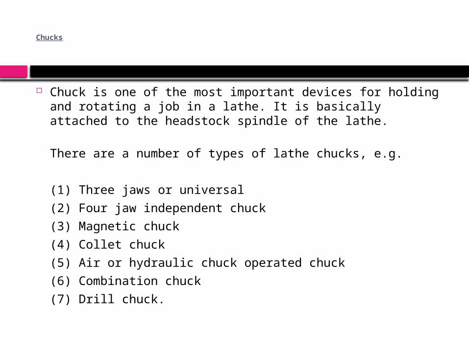
Chucks
Chuck is one of the most important devices for holding and rotating a job in a lathe. It is basically attached to the headstock spindle of the lathe.
There are a number of types of lathe chucks, e.g.
(1) Three jaws or universal(2) Four jaw independent chuck(3) Magnetic chuck(4) Collet chuck(5) Air or hydraulic chuck operated chuck(6) Combination chuck(7) Drill chuck.

Face plates
Face plates are employed for holding jobs, which cannot be conveniently held between centers or by chucks. A face plate possesses the radial, plain and T slots for holding jobs or work-pieces by bolts and clamps. Face plates consist of a circular disc bored out and threaded to fit the nose of the lathe spindle. They are heavily constructed and have strong thick ribs on the back. They have slots cut into them, therefore nuts, bolts, clamps and angles are used to hold the jobs on the face plate. They are accurately machined and ground.

Angle plates
Angle plate is a cast iron plate having two faces machined to make them absolutely at right angles to each other. Holes and slots are provided on both faces so that it may be clamped on a faceplate and can hold the job or workpiece on the other face by bolts and clamps. The plates are used in conjunction with a face plate when the holding surface of the job should be kept horizontal.

Mandrels
A mandrel is a device used for holding and rotating a hollow job that has been previously drilled or bored. The job revolves with the mandrel, which is mounted between two centers.
It is rotated by the lathe dog and the catch plate and it drives the work by friction. Different types of mandrels are employed according to specific requirements. It is hardened and tempered steel shaft or bar with 60° centers, so that it can be mounted between centers. It holds and locates a part from its center hole. The mandrel is always rotated with the help of a lathe dog; it is never placed in a chuck for turning the job. A mandrel unlike an arbor is a job holding device rather than a cutting tool holder. A bush can be faced and turned by holding the same on a mandrel between centers. It is generally used in order to machine the entire length of a hollow job

Rests
A rest is a lathe device, which supports a long slender job, when it is turned between centers or by a chuck, at some intermediate point to prevent bending of the job due to its own weight and vibration set up due to the cutting force that acts on it. The two types of rests commonly used for supporting a long job in an engine lathe are the steady or centre rest and the follower rest.

Cutting Speed
Cutting speed for lathe work may be defined as the rate in meters per minute at which the surface of the job moves past the cutting tool.. Too slow cutting speeds reduce productivity and increase manufacturing costs whereas too high cutting speeds result in overheating of the tool and premature failure of the cutting edge of the tool.
The following factors affect the cutting speed:
Kind of material being cut, Cutting tool material, Shape of cutting tool, Rigidity of machine tool and the job piece and Type of cutting fluid being used

Feed
Feed is defined as the distance that a tool advances into the work during one revolution of the headstock spindle. It is usually given as a linear movement per revolution of the spindle or job. During turning a job on the center lathe, the saddle and the tool post move along the bed of the lathe for a particular feed for cutting along the length of the rotating job.

Lathe Operations
For performing the various machining operations in a lathe, the job is being supported and driven by anyone of the following methods.
1. Job is held and driven by chuck with the other end supported on the tail stock centre.2. Job is held between centers and driven by carriers and catch plates.3. Job is held on a mandrel, which is supported between centers and driven by carriers and catch plates.4. Job is held and driven by a chuck or a faceplate or an angle plate.

Lathe Operations

Lathe Operations

Lathe Operations

Tapers and Taper Turning
A taper is defined as a uniform increase or decrease in diameter of a piece of work measured along its length. In a lathe machine, taper turning means to produce a conical surface by gradual reduction in diameter from a cylindrical job. Taper in the British System is expressed in taper per foot or taper per inch.
Taper per inch = (D – d) /lWhere,D = is the diameter of the large end of cylindrical job,d = is the diameter of the small end of cylindrical job, andl = is the length of the taper of cylindrical job, all expressed in inches,

Tapers and Taper TurningA taper is generally turned in a lathe by feeding the tool at an angle to the axis of rotation of the work piece. The angle formed by the path of the tool with the axis of the work piece should correspond to the half taper angle.
A taper can be turned by anyone of the following methods:
1. By swiveling the compound rest,2. By setting over the tailstock centre,3. By a broad nose form tool,4. By a taper turning attachment,5. By combining longitudinal and cross feed in a special lathe and6. By using numerical control lathe

Drilling On a Lathe
For producing holes in jobs on lathe, the job is held in a chuck or on a face plate. The drill is held in the position of tailstock and which is brought nearer the job by moving the tailstock along the guide ways, the thus drill is fed against the rotating job